Embed Size (px)
Citation preview

OWNER’SMANUAL
ENtREpRENEUR
INSTALLATION • OPERATIONMAINTENANCE • BATHTUB / SHOWER REPAIR
WHIRLPOOL • ACTIV-AIR
produi tsneptune.com
Save these instructions for further use

2 OWNER’S MANUAL ENtREpRENEUR
table of contentsINTRODUCTION
Important safety instructions 3
Summary of precautions 3
INSTALLATIONBathtub installation: preparation 3
Required tools 3
Required materials 3
Site preparation 4
Protective foam packaging 4
Recessed installation 4
Podium installation 5
Undermount bathtub installation 6
Faucet installation 6
System hook-up (electrical installation) 6
Finishing walls, decks and podiums 9
Optional bathtub skirt installation 9
Fixed height skirts 9
Adjustable height skirts 10
OPERATING INSTRUCTIONSShower and shower base installation 11
Whirlpool and air controls 13
MAINTENANCERoutine cleaning 13
Whirlpool 13
Activ-Air 13
Light bulb replacement 13
ACRYLIC REPAIRSStains 13
Minor scratch repair 13
Major damage repair 13
TROUBLESHOOTING 14
WARRANTY 15
IMPORTANT INFORMATION TO kEEP 15
Thank you for selecting a Produits
Neptune product. Your trust plays a
great part in our company’s success.
Your new Produits Neptune bathtub/
shower is a top of the line product that
will give you years of pleasure and
relaxation if it is installed and main-
tained correctly.
We encourage you to read and under-
stand all of the safety, installation and
maintenance instructions included in
this manual. It is strongly recommended
that the installation of your bathtub/
shower be carried out by qualified and
accredited professionals in accordance
with governmental building codes and
by-laws.
OWNER’S MANUAL ENtREpRENEUR 3
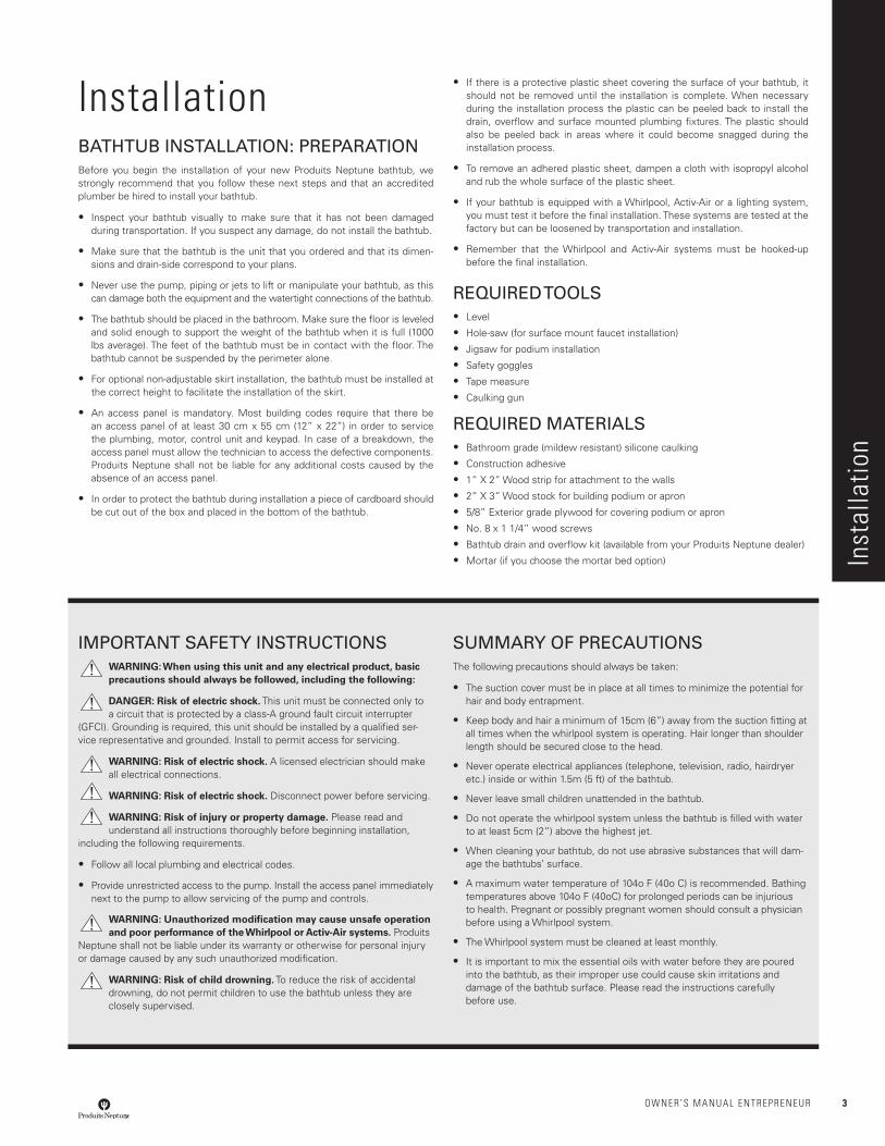
InstallationBATHTUB INSTALLATION: PREPARATIONBefore you begin the installation of your new Produits Neptune bathtub, we strongly recommend that you follow these next steps and that an accredited plumber be hired to install your bathtub.
• Inspect your bathtub visually to make sure that it has not been damaged during transportation. If you suspect any damage, do not install the bathtub.
• Make sure that the bathtub is the unit that you ordered and that its dimen-sions and drain-side correspond to your plans.
• Never use the pump, piping or jets to lift or manipulate your bathtub, as this can damage both the equipment and the watertight connections of the bathtub.
• The bathtub should be placed in the bathroom. Make sure the floor is leveled and solid enough to support the weight of the bathtub when it is full (1000 lbs average). The feet of the bathtub must be in contact with the floor. The bathtub cannot be suspended by the perimeter alone.
• For optional non-adjustable skirt installation, the bathtub must be installed at the correct height to facilitate the installation of the skirt.
• An access panel is mandatory. Most building codes require that there be an access panel of at least 30 cm x 55 cm (12” x 22”) in order to service the plumbing, motor, control unit and keypad. In case of a breakdown, the access panel must allow the technician to access the defective components. Produits Neptune shall not be liable for any additional costs caused by the absence of an access panel.
• In order to protect the bathtub during installation a piece of cardboard should be cut out of the box and placed in the bottom of the bathtub.
• If there is a protective plastic sheet covering the surface of your bathtub, it should not be removed until the installation is complete. When necessary during the installation process the plastic can be peeled back to install the drain, overflow and surface mounted plumbing fixtures. The plastic should also be peeled back in areas where it could become snagged during the installation process.
• To remove an adhered plastic sheet, dampen a cloth with isopropyl alcohol and rub the whole surface of the plastic sheet.
• If your bathtub is equipped with a Whirlpool, Activ-Air or a lighting system, you must test it before the final installation. These systems are tested at the factory but can be loosened by transportation and installation.
• Remember that the Whirlpool and Activ-Air systems must be hooked-up before the final installation.
REQUIRED TOOLS• Level
• Hole-saw (for surface mount faucet installation)
• Jigsaw for podium installation
• Safety goggles
• Tape measure
• Caulking gun
REQUIRED MATERIALS• Bathroom grade (mildew resistant) silicone caulking
• Construction adhesive
• 1” X 2” Wood strip for attachment to the walls
• 2” X 3” Wood stock for building podium or apron
• 5/8” Exterior grade plywood for covering podium or apron
• No. 8 x 1 1/4” wood screws
• Bathtub drain and overflow kit (available from your Produits Neptune dealer)
• Mortar (if you choose the mortar bed option) Inst
alla
tion
IMPORTANT SAFETY INSTRUCTIONSWARNING: When using this unit and any electrical product, basic precautions should always be followed, including the following:
DANGER: Risk of electric shock. This unit must be connected only to a circuit that is protected by a class-A ground fault circuit interrupter
(GFCI). Grounding is required, this unit should be installed by a qualified ser-vice representative and grounded. Install to permit access for servicing.
WARNING: Risk of electric shock. A licensed electrician should make all electrical connections.
WARNING: Risk of electric shock. Disconnect power before servicing.
WARNING: Risk of injury or property damage. Please read and understand all instructions thoroughly before beginning installation,
including the following requirements.
• Follow all local plumbing and electrical codes.
• Provide unrestricted access to the pump. Install the access panel immediately next to the pump to allow servicing of the pump and controls.
WARNING: Unauthorized modification may cause unsafe operation and poor performance of the Whirlpool or Activ-Air systems. Produits
Neptune shall not be liable under its warranty or otherwise for personal injury or damage caused by any such unauthorized modification.
WARNING: Risk of child drowning. To reduce the risk of accidental drowning, do not permit children to use the bathtub unless they are closely supervised.
SUMMARY OF PRECAUTIONSThe following precautions should always be taken:
• The suction cover must be in place at all times to minimize the potential for hair and body entrapment.
• Keep body and hair a minimum of 15cm (6”) away from the suction fitting at all times when the whirlpool system is operating. Hair longer than shoulder length should be secured close to the head.
• Never operate electrical appliances (telephone, television, radio, hairdryer etc.) inside or within 1.5m (5 ft) of the bathtub.
• Never leave small children unattended in the bathtub.
• Do not operate the whirlpool system unless the bathtub is filled with water to at least 5cm (2”) above the highest jet.
• When cleaning your bathtub, do not use abrasive substances that will dam-age the bathtubs’ surface.
• A maximum water temperature of 104o F (40o C) is recommended. Bathing temperatures above 104o F (40oC) for prolonged periods can be injurious to health. Pregnant or possibly pregnant women should consult a physician before using a Whirlpool system.
• The Whirlpool system must be cleaned at least monthly.
• It is important to mix the essential oils with water before they are poured into the bathtub, as their improper use could cause skin irritations and damage of the bathtub surface. Please read the instructions carefully before use.
4 OWNER’S MANUAL ENtREpRENEUR
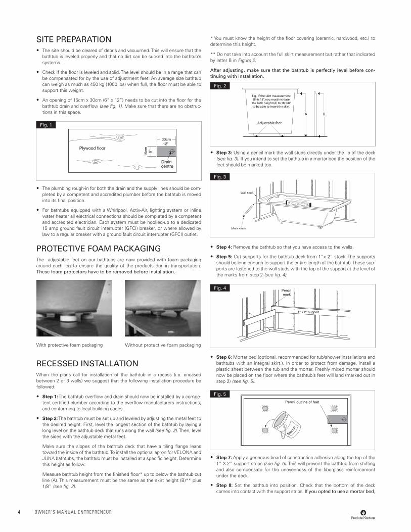
SITE PREPARATION• The site should be cleared of debris and vacuumed. This will ensure that the
bathtub is leveled properly and that no dirt can be sucked into the bathtub’s systems.
• Check if the floor is leveled and solid. The level should be in a range that can be compensated for by the use of adjustment feet. An average size bathtub can weigh as much as 450 kg (1000 lbs) when full, the floor must be able to support this weight.
• An opening of 15cm x 30cm (6” x 12”) needs to be cut into the floor for the bathtub drain and overflow (see fig. 1). Make sure that there are no obstruc-tions in this space.
• The plumbing rough-in for both the drain and the supply lines should be com-pleted by a competent and accredited plumber before the bathtub is moved into its final position.
• For bathtubs equipped with a Whirlpool, Activ-Air, lighting system or inline water heater all electrical connections should be completed by a competent and accredited electrician. Each system must be hooked-up to a dedicated 15 amp ground fault circuit interrupter (GFCI) breaker, or where allowed by law to a regular breaker with a ground fault circuit interrupter (GFCI) outlet.
PROTECTIVE FOAM PACkAGINGThe adjustable feet on our bathtubs are now provided with foam packaging around each leg to ensure the quality of the products during transportation. These foam protectors have to be removed before installation.
With protective foam packaging Without protective foam packaging
RECESSED INSTALLATIONWhen the plans call for installation of the bathtub in a recess (i.e. encased between 2 or 3 walls) we suggest that the following installation procedure be followed:
• Step 1: The bathtub overflow and drain should now be installed by a compe-tent certified plumber according to the overflow manufacturers instructions, and conforming to local building codes.
• Step 2: The bathtub must be set up and leveled by adjusting the metal feet to the desired height. First, level the longest section of the bathtub by laying a long level on the bathtub deck that runs along the wall (see fig. 2). Then, level the sides with the adjustable metal feet.
Make sure the slopes of the bathtub deck that have a tiling flange leans toward the inside of the bathtub. To install the optional apron for VELONA and JUNA bathtubs, the bathtub must be installed at a specific height. Determine this height as follow:
Measure bathtub height from the finished floor* up to below the bathtub cut line (A). This measurement must be the same as the skirt height (B)** plus 1/8” (see fig. 2).
* You must know the height of the floor covering (ceramic, hardwood, etc.) to determine this height.
** Do not take into account the full skirt measurement but rather that indicated by letter B in Figure 2.
After adjusting, make sure that the bathtub is perfectly level before con-tinuing with installation.
• Step 3: Using a pencil mark the wall studs directly under the lip of the deck (see fig. 3). If you intend to set the bathtub in a mortar bed the position of the feet should be marked too.
• Step 4: Remove the bathtub so that you have access to the walls.
• Step 5: Cut supports for the bathtub deck from 1”x 2” stock. The supports should be long enough to support the entire length of the bathtub. These sup-ports are fastened to the wall studs with the top of the support at the level of the marks from step 2 (see fig. 4).
• Step 6: Mortar bed (optional, recommended for tub/shower installations and bathtubs with an integral skirt.). In order to protect from damage, install a plastic sheet between the tub and the mortar. Freshly mixed mortar should now be placed on the floor where the bathtub’s feet will land (marked out in step 2) (see fig. 5).
• Step 7: Apply a generous bead of construction adhesive along the top of the 1” X 2” support strips (see fig. 6). This will prevent the bathtub from shifting and also compensate for the unevenness of the fiberglass reinforcement under the deck.
• Step 8: Set the bathtub into position. Check that the bottom of the deck comes into contact with the support strips. If you opted to use a mortar bed,
Plywood floor
Draincentre
Fig. 1
A B
Adjustable feet
E.g., If the skirt measurement(B) is 18", you must increase
the bath height (A) to 18 1/8"to be able to insert the skirt.
Fig. 2
Fig. 3
Fig. 4
Fig. 5
OWNER’S MANUAL ENtREpRENEUR 5
check that the mortar has spread out and that the feet are supported. Add more mortar if necessary. If you did not use a mortar bed, secure the metal feet using the construction adhesive.
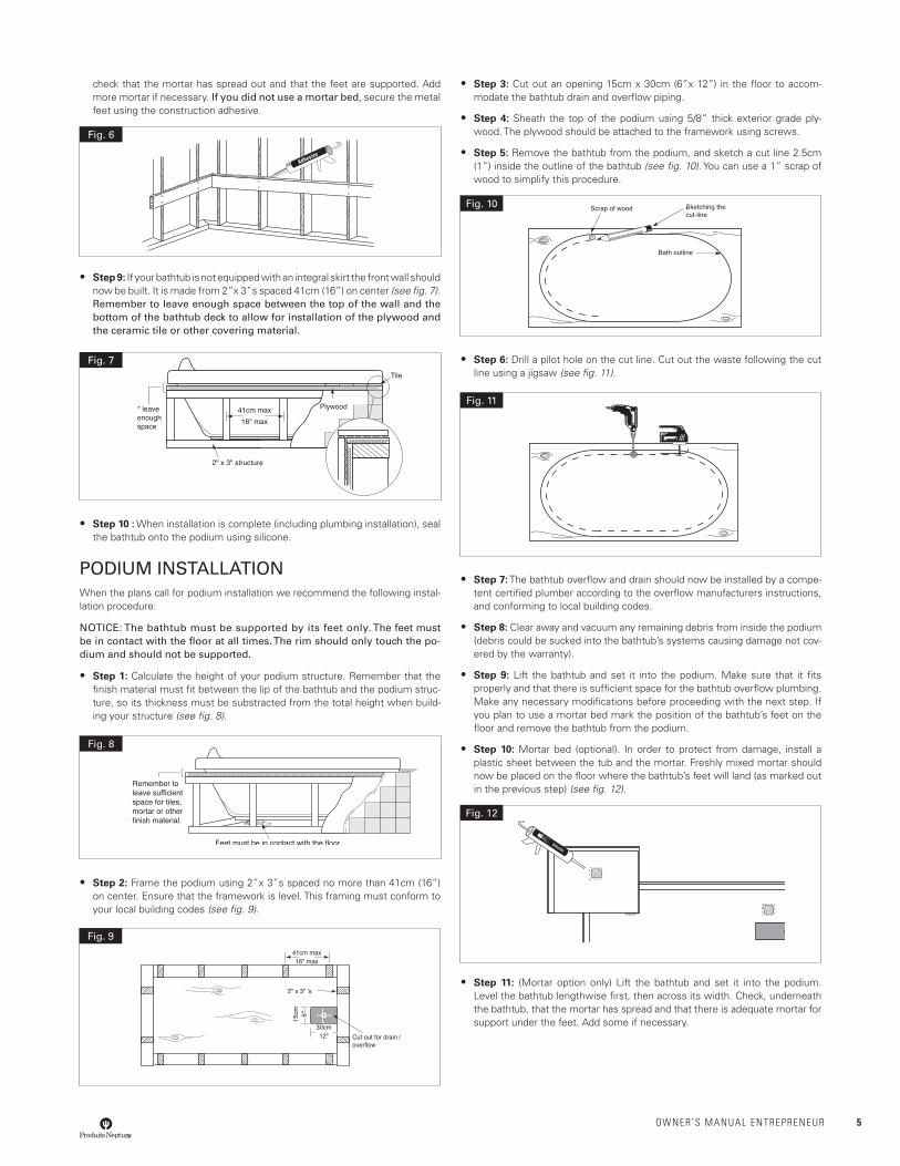
• Step 9: If your bathtub is not equipped with an integral skirt the front wall should now be built. It is made from 2”x 3”s spaced 41cm (16”) on center (see fig. 7). Remember to leave enough space between the top of the wall and the bottom of the bathtub deck to allow for installation of the plywood and the ceramic tile or other covering material.
• Step 10 : When installation is complete (including plumbing installation), seal the bathtub onto the podium using silicone.
PODIUM INSTALLATIONWhen the plans call for podium installation we recommend the following instal-lation procedure:
NOTICE: The bathtub must be supported by its feet only. The feet must be in contact with the floor at all times. The rim should only touch the po-dium and should not be supported.
• Step 1: Calculate the height of your podium structure. Remember that the finish material must fit between the lip of the bathtub and the podium struc-ture, so its thickness must be substracted from the total height when build-ing your structure (see fig. 8).
• Step 2: Frame the podium using 2”x 3”s spaced no more than 41cm (16”) on center. Ensure that the framework is level. This framing must conform to your local building codes (see fig. 9).
• Step 3: Cut out an opening 15cm x 30cm (6”x 12”) in the floor to accom-modate the bathtub drain and overflow piping.
• Step 4: Sheath the top of the podium using 5/8” thick exterior grade ply-wood. The plywood should be attached to the framework using screws.
• Step 5: Remove the bathtub from the podium, and sketch a cut line 2.5cm (1”) inside the outline of the bathtub (see fig. 10). You can use a 1” scrap of wood to simplify this procedure.
• Step 6: Drill a pilot hole on the cut line. Cut out the waste following the cut line using a jigsaw (see fig. 11).
• Step 7: The bathtub overflow and drain should now be installed by a compe-tent certified plumber according to the overflow manufacturers instructions, and conforming to local building codes.
• Step 8: Clear away and vacuum any remaining debris from inside the podium (debris could be sucked into the bathtub’s systems causing damage not cov-ered by the warranty).
• Step 9: Lift the bathtub and set it into the podium. Make sure that it fits properly and that there is sufficient space for the bathtub overflow plumbing. Make any necessary modifications before proceeding with the next step. If you plan to use a mortar bed mark the position of the bathtub’s feet on the floor and remove the bathtub from the podium.
• Step 10: Mortar bed (optional). In order to protect from damage, install a plastic sheet between the tub and the mortar. Freshly mixed mortar should now be placed on the floor where the bathtub’s feet will land (as marked out in the previous step) (see fig. 12).
• Step 11: (Mortar option only) Lift the bathtub and set it into the podium. Level the bathtub lengthwise first, then across its width. Check, underneath the bathtub, that the mortar has spread and that there is adequate mortar for support under the feet. Add some if necessary.
Fig. 6
Fig. 7
Fig. 8
Fig. 9
Fig. 10
Fig. 11
Fig. 12
6 OWNER’S MANUAL ENtREpRENEUR
UNDERMOUNT BATHTUB INSTALLATION • Step 1: Build a podium strong enough to support the weight of the material
chosen to be put on top of it. Make sure the bathtub does not support the podium deck: there has to be a gap of about 1/16” between the bottom of the podium deck and the top of the bathtub deck.
• Step 2: Install the bathtub based on the instructions given in this guide.
• Step 3: Install the podium deck based on the instructions supplied by the manufacturer and apply a bead of silicone between the podium deck and the bathtub deck. Immediately remove any excess sealant with a clean cloth. The deck of the bathtub is designed with a slight slope, to ensure that water flows down to the inside of the bathtub. As a result, the size of the gap will vary according to how much of the bathtub deck you want to be covered by the podium deck.
The podium deck is close to the outside edge. The gap between the podium deck and the bathtub is narrow; install the podium deck over the bathtub and apply a small bead of silicone caulk (see fig. 13).
The podium deck is completely covering the bathtub deck. Install the podium deck over the bathtub. In this case the gap is larger and will required a larger silicone bead, but it will not be visible since it will be entirely covered by the podium deck (see fig. 14).
FAUCET INSTALLATION• Step 1: (Bathtub mounted faucets) Faucets can be mounted either onto the
podium, or they can be attached directly to the bathtub or to the wall. When attachment to the bathtub is called for, great care must be taken when drilling through the acrylic.
• Align the faucet knob handles and ensure they are level before drilling the holes
• Always use a sharp hole-saw with a pilot bit that extends at least 1/4” below it.
• The hole must always be larger than the fitting, forcing an object through a hole that is too small will damage the acrylic.
• Drill slowly and steadily letting the tool do the work. This will help to reduce heat build-up and binding at the acrylic surface.
• When installing the fixtures never over-tighten them as this can cause damage to the acrylic surface.
• Step 2: Once the plumbing installation is completed, it needs to be leak tested. We recommend a 20 minute soak test. Fill the bathtub above the overflow level and let stand for 20 minutes. If no leaking is detected on the plumbing hook-ups continue with the installation.
SYSTEM HOOk-UP (electrical installation)All electrical connections should be done by a competent licensed electrician in accordance with the local building codes. An access panel is mandatory. Most building codes require that there be an access panel of at least 30 cm x 55 cm (12” x 22”) in order to service the plumbing, motor, control unit and keypad. In case of a breakdown, the access panel must allow the technician to access the defective components. Produits Neptune shall not be liable for any additional costs caused by the absence of an access panel.
All components exceeding 6 AMP (pump, blower or water heater) must be connected to an independent 15-Amp ground fault circuit interrupter (GFCI) breaker. Where allowed by law they can be hooked up to GFCI outlets connected to a regular breaker.
The bathtub systems and controls are designed to operate on 110/120 Volt AC 60 Hz (North America).
• Step 1: Turn off the power to the bathtub circuit at the electrical panel.
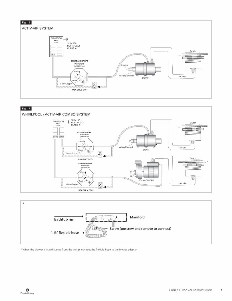
• Step 2: Hook up the wiring from the control module and/or pump and/or inline heater and/or light to the circuit panel using the appropriate cable gauge (see fig. 16 and 17). If the distance from the electrical panel to the bathtub is further than 30 m (100 ft), refer to your local building code to make sure that a sufficient gauge cable is used.
• Step 3: Air switch: The hole for the switch can is drilled at the factory. The switch can includes a self-sealing gasket that will hold it in place. Depend-ing on your model it will plug directly into the pump and/or control module and/or lighting power supply. (see fig. 16 and 17).
• Step 4: Mood light: The optional bathtub light is operated using an air switch. The air switch for mood light is factory installed.
The air tube is attached to the barbed fittings on both the bottom of the switch and on the light control module which houses the transformer. The housing for the light is factory installed. Please see page 13 for light bulb replacement instructions.
Electrical hook-up. The control box comes with two (2) wires. One of them is identified by the words LOAD/CHARGE while the other reads LINE/LIGNE. The wire marked “LINE” is used to connect the control box to the 115 Volt AC 60 Hz. The wire marked “LOAD” is not used for this installation. However, it is recommended to protect the ends of the wire.
• Step 5: Optional in-line water heater: The in-line water heater has a built-in pressure switch that automatically turns the unit on only when the whirlpool pump is operating. There is a red light at the top of the unit, which will be illuminated when the unit is in operation. No further connections other than those in step 2 are necessary. (see fig.18)
• Step 6: System test: Now that the electrical installation is complete, the power can be turned on at the electrical panel. The bathtub should be filled above the level of the jets and the system should run for twenty minutes. If no leaks are detected and all of the systems are functioning normally you may proceed with the remainder of the installation.
Fig. 15
WHIRLPOOL
Silicone1/16”
Podium deck
Bathtub
Fig. 13
Silicone
Podium deck
Bathtub
1/16”
Fig. 14
OWNER’S MANUAL ENtREpRENEUR 7
* When the blower is at a distance from the pump, connect the flexible hose to the blower adaptor.
Fig. 16
ACTIV-AIR SYSTEM
Fig. 17
WHIRLPOOL / ACTIV-AIR COMBO SYSTEM
Bathtub rim
1 ½" �exible hoseScrew (unscrew and remove to connect)
*

8 OWNER’S MANUAL ENtREpRENEUR
Fig. 18
HEATER
Push and turn to fit and lock
Fig. 19
LIGHT
OWNER’S MANUAL ENtREpRENEUR 9
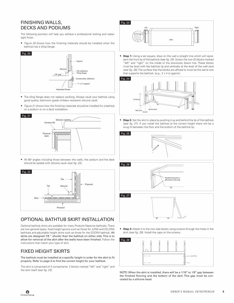
FINISHING WALLS, DECkS AND PODIUMSThe following pointers will help you achieve a professional looking and water-tight finish.
• Figure 20 shows how the finishing materials should be installed when the bathtub has a tiling flange.
• The tiling flange does not replace caulking. Always caulk your bathtub using good quality, bathroom grade (mildew resistant) silicone caulk.
• Figure 21 shows how the finishing materials should be installed for a bathtub on a podium or on a deck installation.
• All 90o angles including those between the walls, the podium and the deck should be sealed with silicone caulk (see fig. 22).
OPTIONAL BATHTUB SkIRT INSTALLATIONOptional bathtub skirts are available for many Produits Neptune bathtubs. There are two general types, fixed height aprons such as those for JUNA and VELONA bathtubs and adjustable height skirts such as those for the EDORA bathtub. All skirts are designed 7/8 ” shorter than the bathtub on either side. This is to allow for removal of the skirt after the walls have been finished. Follow the instructions that match your type of skirt.
FIXED HEIGHT SkIRTSThe bathtub must be installed at a specific height in order for the skirt to fit properly. Refer to page 4 to find the correct height for your bathtub.
The skirt is comprised of 3 components: 2 blocks marked “left” and “right” and the skirt itself (see fig. 23).
• Step 1: Using a set square, draw on the wall a straight line which will repre-sent the front lip of the bathtub (see fig. 25). Screw the two (2) blocks marked “left” and “right” on the inside of the previously drawn line. These blocks must be level with the bathtub lip and vertically at the level of the wall stud (see fig. 26). The surface that the blocks are affixed to must be the same one that supports the bathtub. (e.g., 2 x 4 or gyproc)
• Step 2: Set the skirt in place by pushing it up and behind the lip of the bathtub (see fig. 27). If you install the bathtub at the correct height there will be a snug fit between the floor and the bottom of the bathtub lip.
• Step 3: Attach it to the two side blocks using screws through the holes in the skirt (see fig. 28). Install the caps on the screws.
NOTE: When the skirt is installed, there will be a 1/16’’ to 1/8’’ gap between the finished flooring and the bottom of the skirt. This gap must be con-cealed by a silicone bead.
Fig. 20
Fig. 21
Fig. 22
Fig. 23
Fig. 24
Fig. 25
Predrill the blocks toaffix them to the wall.
Fig. 26
Fig. 27
Fig. 28
10 OWNER’S MANUAL ENtREpRENEUR
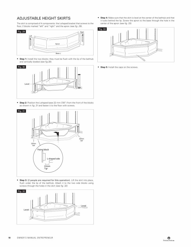
ADJUSTABLE HEIGHT SkIRTSThe skirt is comprised of 4 components: the L-shaped bracket that screws to the floor, 2 blocks marked “left” and “right” and the apron (see fig. 29).
• Step 1: Install the two blocks: they must be flush with the lip of the bathtub and vertically leveled (see fig.30).
• Step 2: Position the L-shaped base 22 mm (7/8”) from the front of the blocks as shown in fig. 31 and fasten it to the floor with screws.
• Step 3: (2 people are required for this operation). Lift the skirt into place, flush under the lip of the bathtub. Attach it to the two side blocks using screws through the holes in the skirt (see fig. 32).
• Step 4: Make sure that the skirt is level at the center of the bathtub and that it tucks behind the lip. Screw the apron to the base through the hole in the center of the apron (see fig. 33).
• Step 5: Install the caps on the screws.
Fig. 29
Level
Fig. 30
22mm7/8”
Fixing block
L-shaped side
Fig. 31
Level
Level
Fig. 32
Fig. 33
OWNER’S MANUAL ENtREpRENEUR 11
Instructions SHOWER AND SHOWER TRAY INSTALLATIONPlease read carefully all the installation and maintenance instructions contained in this guide. We strongly recommend the installation being done by a qualified and authorized specialist, in accordance with building codes and by-laws.
This quality product was thoroughly inspected in factory against any manufac-turing defect before being packed. However, if this product is defective, do not proceed to the installation and inform your retailer immediately.
The installation of a defective product or a bad installation cancels the manu-facturer’s guarantee. To honor your guarantee, you must keep your purchase invoice or provide us a proof of purchase by referring to your retailer.
PREPARATION
Before installing your new PRODUITS NEPTUNE shower, we strongly recom-mend you to follow these few simple steps:
• Prior to removing your old shower, carefully inspect the new one for damage. Do not install a damaged unit. Please contact your retailer for assistance.
• Make sure the shower you have received is the one you ordered and that the dimensions are exact.
• Ensure plumbing rough-in for both the drain and the supply lines are com-pleted according to your shower or shower base’s dimensions.
• The floor area where your shower will be installed must be structurally sound and strong enough to hold the shower and an adult’s weight. Also make sure that the walls and floor are square, plumb and level. If need be, level the floor with a floor leveler.
• It is essential to have an access panel for plumbing maintenance. Most of the building codes generally require the installation of an access panel of a minimum of 30 X 50 cm to facilitate plumbing maintenance.
REQUIRED TOOLS
• Safety goggles
• Drill
• Screwdriver
• Paper and pencil
• Tape measure
• Level
• Hammer
• Set square
• Drill bit
REQUIRED MATERIALS
• Silicone sealant (mildew resistant)
• Construction glue
• Shims (cedar shingles)
• Standard or self-drilling screws
• Mortar (optional)
PREPARATION OF THE SITE
• Sweep the floor to remove construction debris and vacuum all remaining dust to ensure that the shower will be level.
• If renovating, remove all existing wall material in order to install shower directly on wall studs.
• Make sure that the wood frame has the appropriate dimensions.
• If you plan on installing a door, you will also need to plan studs to receive the fastener screws when installing the jambs. Please refer to the installation guide provided with the door.
• All plumbing rough-in for both the drain and the supply should be completed before installing the shower.
• Check the distance between the wall, the shower and the studs to ensure that your valves and fittings fit well.
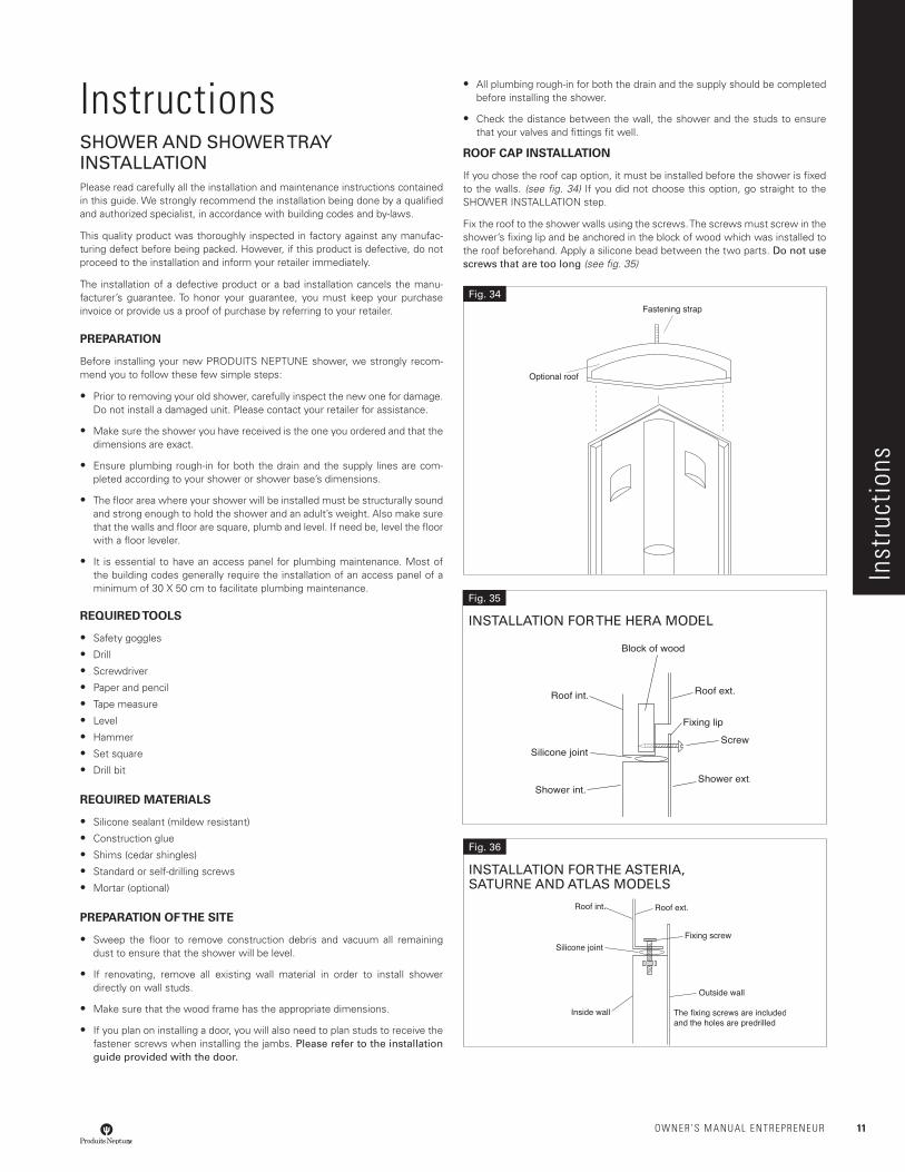
ROOF CAP INSTALLATION
If you chose the roof cap option, it must be installed before the shower is fixed to the walls. (see fig. 34) If you did not choose this option, go straight to the SHOWER INSTALLATION step.
Fix the roof to the shower walls using the screws. The screws must screw in the shower’s fixing lip and be anchored in the block of wood which was installed to the roof beforehand. Apply a silicone bead between the two parts. Do not use screws that are too long (see fig. 35)
Fig. 34
Inst
ruct
ions
Fig. 35
INSTALLATION FOR THE HERA MODEL
Fig. 36
INSTALLATION FOR THE ASTERIA, SATURNE AND ATLAS MODELS
12 OWNER’S MANUAL ENtREpRENEUR
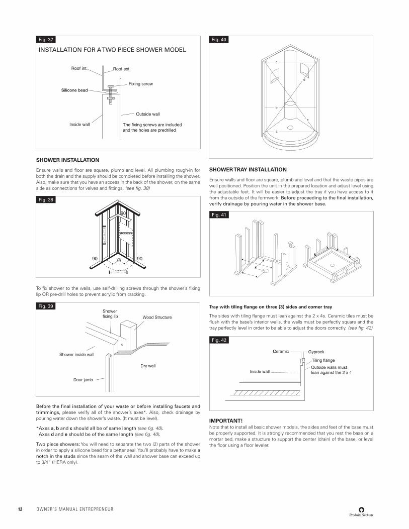
SHOWER INSTALLATION
Ensure walls and floor are square, plumb and level. All plumbing rough-in for both the drain and the supply should be completed before installing the shower. Also, make sure that you have an access in the back of the shower, on the same side as connections for valves and fittings. (see fig. 38)
To fix shower to the walls, use self-drilling screws through the shower’s fixing lip OR pre-drill holes to prevent acrylic from cracking.
Before the final installation of your waste or before installing faucets and trimmings, please verify all of the shower’s axes*. Also, check drainage by pouring water down the shower’s waste. (It must be level).
* Axes a, b and c should all be of same length (see fig. 40). Axes d and e should be of the same length (see fig. 40).
Two piece showers: You will need to separate the two (2) parts of the shower in order to apply a silicone bead for a better seal. You’ll probably have to make a notch in the studs since the seam of the wall and shower base can exceed up to 3/4” (HERA only).
SHOWER TRAY INSTALLATION
Ensure walls and floor are square, plumb and level and that the waste pipes are well positioned. Position the unit in the prepared location and adjust level using the adjustable feet. It will be easier to adjust the tray if you have access to it from the outside of the formwork. Before proceeding to the final installation, verify drainage by pouring water in the shower base.
Tray with tiling flange on three (3) sides and corner tray
The sides with tiling flange must lean against the 2 x 4s. Ceramic tiles must be flush with the base’s interior walls, the walls must be perfectly square and the tray perfectly level in order to be able to adjust the doors correctly. (see fig. 42)
IMPORTANT!Note that to install all basic shower models, the sides and feet of the base must be properly supported. It is strongly recommended that you rest the base on a mortar bed, make a structure to support the center (drain) of the base, or level the floor using a floor leveler.
Silicone bead
Fig. 37
INSTALLATION FOR A TWO PIECE SHOWER MODEL
Fig. 38
Fig. 39
Fig. 40
Fig. 41
Fig. 42
OWNER’S MANUAL ENtREpRENEUR 13
WHIRLPOOL AND AIR CONTROLSProduits Neptune’s whirlpool system increases the massaging effect by drawing air into the jets (Venturi effect). The air controls are installed on the inner sides of the bathtub. The air is dispatched through the jets to increase the messaging effect.
MaintenanceROUTINE CLEANINGIn order to protect the acrylic surface of your Produits Neptune bathtub and show-er it should be cleaned only with a non-abrasive liquid bathroom cleaner such as liquid Spic and Span or a detergent specifically formulated for acrylic. NEVER USE ABRASIVE POWDER (VIM, AJAX etc.), PETROLEUM DISTILLATES OR OTHER STRONG SOLVENTS TO CLEAN THE SURFACE OF YOUR BATHTUB OR SHOWER.
WHIRLPOOLProduits Neptune recommends that the following cleaning procedures be undertaken monthly as follows:
1. Fill the bathtub with hot water 5 cm (2”) above the jets’ level.
2. Add 2-Cups of vinegar or 1/4 cup of liquid dishwasher soap.
3. Run the whirlpool for approximately 5 minutes.
4. Let the bathtub soak for a 1/2 hour.
5. Run the whirlpool for another 5 minutes.
6. Drain the bathtub.
7. Rinse with cold water.
ACTIV-AIRIf your Produits Neptune bathtub is fitted with the Activ-Air system most of the routine maintenance is eliminated by the fact that the electronic control module features a built-in automatic drying cycle. This cycle, that initiates 20 minutes after the blower has stopped, removes all remaining stagnant water from the air jets above the return valve. If your bathtub is used without activating the Activ-Air system, it should be activated and turned off rapidly so that the drying cycle will automatically start 20 minutes later.
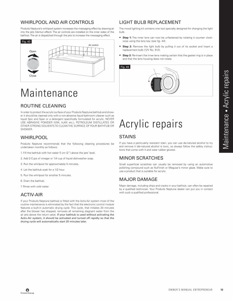
LIGHT BULB REPLACEMENTThe mood lighting kit contains one tool specially designed for changing the light bulb.
• Step 1: The inner lens can now be unfastened by rotating it counter- clock-wise using the lens key (see fig. 44).
• Step 2: Remove the light bulb by pulling it out of its socket and insert a replacement bulb (12V No. 912).
• Step 3: Re-insert the inner lens making certain that the gasket ring is in place and that the lens housing does not rotate.
Acrylic repairsSTAINSIf you have a particularly resistant stain, you can use de-natured alcohol to try and remove it (de-natured alcohol is toxic, so always follow the safety instruc-tions that come with it and wear rubber gloves).
MINOR SCRATCHESSmall superficial scratches can usually be removed by using an automotive polishing compound such as NuFinish or Meguiar’s mirror glaze. Make sure to use a product that is suitable for acrylic.
MAJOR DAMAGEMajor damage, including chips and cracks in your bathtub, can often be repaired by a qualified technician. Your Produits Neptune dealer can put you in contact with such a qualified professional.
Mai
nten
ance
• A
cryl
ic re
pairs
Fig. 44
Air controlFig. 43
Open
Close
14 OWNER’S MANUAL ENtREpRENEUR
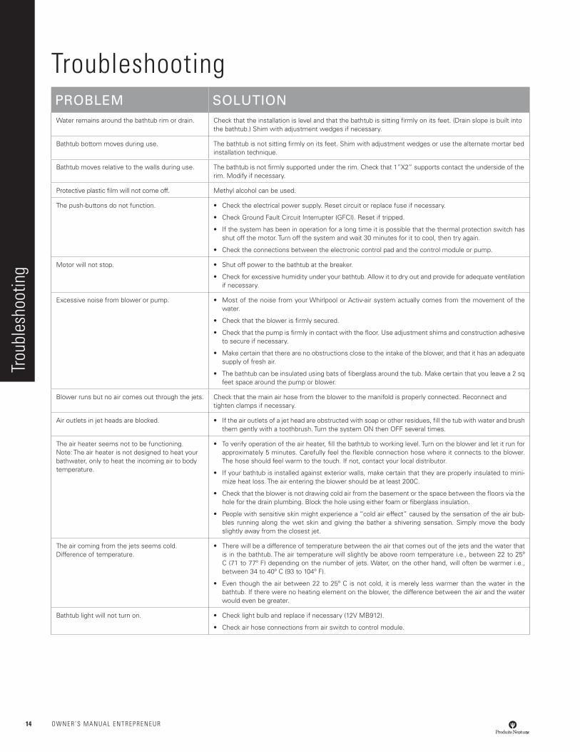
troubleshootingPROBLEM SOLUTIONWater remains around the bathtub rim or drain. Check that the installation is level and that the bathtub is sitting firmly on its feet. (Drain slope is built into
the bathtub.) Shim with adjustment wedges if necessary.
Bathtub bottom moves during use. The bathtub is not sitting firmly on its feet. Shim with adjustment wedges or use the alternate mortar bed installation technique.
Bathtub moves relative to the walls during use. The bathtub is not firmly supported under the rim. Check that 1”X2” supports contact the underside of the rim. Modify if necessary.
Protective plastic film will not come off. Methyl alcohol can be used.
The push-buttons do not function. • Check the electrical power supply. Reset circuit or replace fuse if necessary.
• Check Ground Fault Circuit Interrupter (GFCI). Reset if tripped.
• If the system has been in operation for a long time it is possible that the thermal protection switch has shut off the motor. Turn off the system and wait 30 minutes for it to cool, then try again.
• Check the connections between the electronic control pad and the control module or pump.
Motor will not stop. • Shut off power to the bathtub at the breaker.
• Check for excessive humidity under your bathtub. Allow it to dry out and provide for adequate ventilation if necessary.
Excessive noise from blower or pump. • Most of the noise from your Whirlpool or Activ-air system actually comes from the movement of the water.
• Check that the blower is firmly secured.
• Check that the pump is firmly in contact with the floor. Use adjustment shims and construction adhesive to secure if necessary.
• Make certain that there are no obstructions close to the intake of the blower, and that it has an adequate supply of fresh air.
• The bathtub can be insulated using bats of fiberglass around the tub. Make certain that you leave a 2 sq feet space around the pump or blower.
Blower runs but no air comes out through the jets. Check that the main air hose from the blower to the manifold is properly connected. Reconnect and tighten clamps if necessary.
Air outlets in jet heads are blocked. • If the air outlets of a jet head are obstructed with soap or other residues, fill the tub with water and brush them gently with a toothbrush. Turn the system ON then OFF several times.
The air heater seems not to be functioning.Note: The air heater is not designed to heat your bathwater, only to heat the incoming air to body temperature.
• To verify operation of the air heater, fill the bathtub to working level. Turn on the blower and let it run for approximately 5 minutes. Carefully feel the flexible connection hose where it connects to the blower. The hose should feel warm to the touch. If not, contact your local distributor.
• If your bathtub is installed against exterior walls, make certain that they are properly insulated to mini-mize heat loss. The air entering the blower should be at least 200C.
• Check that the blower is not drawing cold air from the basement or the space between the floors via the hole for the drain plumbing. Block the hole using either foam or fiberglass insulation.
• People with sensitive skin might experience a “cold air effect” caused by the sensation of the air bub-bles running along the wet skin and giving the bather a shivering sensation. Simply move the body slightly away from the closest jet.
The air coming from the jets seems cold. Difference of temperature.
• There will be a difference of temperature between the air that comes out of the jets and the water that is in the bathtub. The air temperature will slightly be above room temperature i.e., between 22 to 25º C (71 to 77º F) depending on the number of jets. Water, on the other hand, will often be warmer i.e., between 34 to 40º C (93 to 104º F).
• Even though the air between 22 to 25º C is not cold, it is merely less warmer than the water in the bathtub. If there were no heating element on the blower, the difference between the air and the water would even be greater.
Bathtub light will not turn on. • Check light bulb and replace if necessary (12V MB912).
• Check air hose connections from air switch to control module.
trou
bles
hoot
ing
OWNER’S MANUAL ENtREpRENEUR 15
Note: Always keep your original bill of sale
Date of purchase:
Name of retailer:
Description of bathtub:
Serial # (indicated underneath the bathtub):
WarrantyProduits Neptune QUALITY
This logo certifies that your bathtub or shower has been inspected and tested by our specialists and that it is compliant with our high Produits Neptune quality standards.
CSA LISTED / Warnock-Hersey
All our products and all our components have received CSA or Warnock-Hersey certification, which attests to their quality and reliability.
WARRANTY BATHTUBS AND SHOWERS
Each Produits Neptune product has been subjected to rigorous quality controls and we guarantee that it conforms to the highest quality standards. In order to ensure a trouble-free installation, we strongly recommend that you read the installation manual and our warranty terms joined with the product carefully before beginning any work. Our warranty covers parts and labor for repairs. Additional costs related to defective product replacement are not covered.
ACRYLIC SHELL: Limited 10-year warranty againstmanufacturing defects.
FIBERGLASS SHELL: Limited 3-year warranty against manufacturing defects.
SYSTEMS: Limited 5-year warranty parts and labor against manufacturing defects (jets, pipes, control, pumps, water heater, blowers, wiring, etc.) and leaks related to manufacturing defects.
Limited 5-year warranty against manufacturing defects related to colored jet trims inside the bathtub.
WARRANTY OPTIONS, DOORS AND DRAINS
Each Produits Neptune product has been subjected to rigorous quality controls and we guarantee that it conforms to the highest quality standards. In order to ensure a trouble-free installation, we strongly recommend that you read the installation manual and our warranty terms joined with the product carefully before beginning any work. Our warranty covers parts for repairs. Additional costs related to defective product replacement are not covered.
OPTIONS: General options such as mood lights, neck pillows, handles and other options, limited 5-year warranty against manufacturing defects on all parts.
DOORS: Limited 10-year warranty against manufacturing defects on all parts other than gaskets, magnets and installation hardware, which have a 1-year warranty against manufacturing defects.
DRAINS: Limited lifetime warranty against manufacturing defects on all parts.
Limited lifetime warranty for chrome finish.
IMPORTANT!
• When a showroom product is sold, the warranty period begins on the date of purchase from Produits Neptune by the retailer.
• For commercial use, all products have a 1-year warranty against manufacturing defects.
Important information to keep
War
rant
y • Im
porta
nt in
form
atio
n to
kee
p
August 2011

16 OWNER’S MANUAL ENtREpRENEUR
Notes