Embed Size (px)
Citation preview
OWNER’S MANUAL

BATTERIES BEDS TOWELS CUPS PLATES SAT NAV DOG BEDS BLINDS AWNINGS CYCLE RACKS GENERATORS RADIOS
HELMETS FISHING RODS CUSHIONS MICROWAVES CLEANING KITS BBQS CHAIRS COOKING UTENSILS TELEVISIONS WATER
CARRIERS UPHOLSTERY REVERSING CAMERAS CLOTHES AIRERS TYRE PRESSURE MONITORS PIR ALARMS SHOWER MATS
BATTERIES BEDS TOWELS CUPS PLATES SAT NAV DOG BEDS BLINDS AWNINGS CYCLE RACKS GENERATOR
S RADIOS HELMETS FISHING RODS CUSHIONS MICROWAVES CLEANING KITS BBQS CHAIRS COOKING UTENSILS TELEVISIONS WATER CARRIERS UPHOLSTERY REVERSING CAMERAS CLOTHES AIRERS TYRE PRESSURE MONITORS PIR ALARMS SHOWER MATS
BATTERIES BEDS TOWELS CUPS PLATES SAT NAV DOG BEDS BLINDS AWNINGS CYCLE RACKS GENERATORS RADIOS HELMETS FISHING
RODS CUSHIONS MICROWAVES CLEANING KITS BBQS CHAIRS COOKING UTENSILS TELEVISIONS WATER CARRIERS UPHOLSTERY REVERSING CAMERAS CLOTHES AIRERS TYRE PRESSURE MONITORS
YOU’LL FIND
THE KITCHEN SINKandEVERYTHING
Visit our store, just off J16 of the M5Or shop online at
www.bailey-parts.co.uk We’re just off the M4/M5 interchange southbound towards the West Country (M5 J16).
Leave the M5 at J16, go left at roundabout, left at next one, take 1st left and turn right.
Unit 600, The Quadrant, Ash Ridge Road, Bristol, BS32 4QA. Call us on 0117 953 8140.
Open 7 days a week! Mon to Sat 8am - 5pm, Sun 11am - 5pm.
online and in store.
1
CO
NTE
NTS
Contents
Introduction ......................................................................................................................... 1
Getting to Know Your Motorhome .................................................................................5
Glossary of Terms ..............................................................................................................9
Safety and Security .......................................................................................................... 12
Preparing to go on holiday ............................................................................................. 17
Before Moving Off ........................................................................................................... 22
Travelling ........................................................................................................................... 25
Setting up on arrival ....................................................................................................... 32
The Water System............................................................................................................ 36
The Gas System ................................................................................................................ 45
The Electrical System ..................................................................................................... 52
Truma Solar Dual Battery Charger ..............................................................................68
The Alde Heating System .............................................................................................. 65
The Seattle Control Panel .............................................................................................. 79
The Whale Space and Water Heater............................................................................86
The Digital Antenna System .......................................................................................... 93
The Media Pack ................................................................................................................98
The Thetford Duplex Oven, Grill and Hob ................................................................. 108
The Microwave Oven - KOR-6L5R ............................................................................... 114
The Dometic Refrigerator ............................................................................................. 125
Surface Care .................................................................................................................... 133
The Thetford C262 Toilet .............................................................................................. 139
Fitted Furniture Configurations ................................................................................... 144
Heki Roof Lights .............................................................................................................. 153
The Remis Window Blinds ............................................................................................. 157
The Fiamma Awning........................................................................................................ 161
Maintenance..................................................................................................................... 165
Warranty ........................................................................................................................... 169

*Price valid until 14 December 2014. A joining fee of £10 applies – this fee is waived if you choose to pay by Direct Debit.
There’s no better value in touring
Discover our many sites on historic estates like Longleat
The Caravan Club
Save £10 a night on pitch fees
Fantastic ferry faresFree glossy monthly magazine
FREE technical help & adviceEnjoy access to over 200 UK sites and 2,500 certificated locations
50% off selected sites mid-week and more
What are you waiting for? Join today www.caravanclub.co.uk/join or call 0800 3286 635
Discover an unrivalled choice of sites and thousands of exclusive destinations, huge savings on everything from new cars and great days out to restaurant meals and show tickets plus a whole host of exclusive services and tailored insurance products. At only £44* The Caravan Club takes you and your money further.
Exclusive member offers including M6 toll savings
Club Together our online community chat, interact, ask, review
TCC A4 Bailey Handbook ad.indd 1 28/11/2013 09:49

3
INTR
OD
UC
TIO
N
Introduction
Congratulations on the purchase of your Bailey motorhome. We would like to welcome you to the prestigious rank of Bailey owner. We are confident that this vehicle will give you many years of enjoyment.
Both the Approach Advance and Autograph ranges of motorhomes have been designed to satisfy the motorhome customer in terms of practicality, comfort, safety and aesthetics.
Depending on the range level, specification and model, this handbook along with its supporting documents contain all the information you need to give you miles of happy travelling. Inside you will find details on how to operate, maintain and service your new Bailey motorhome.
So you know how to safely and correctly use your motorhome and its equipment. To avoid risk to yourself and other occupants, it is important that you observe the recommendations and precautions detailed in both the Owners Manual and Service Handbook. Supplementary user guides for fitted equipment featured in this handbook can also be found on relevant manufacturers website.
Always consult your motorhome selling retailer to report any issues and also before fitting any additional equipment to your motorhome.
The fitting of electrical equipment or accessories which are not recommended by Peugeot or Bailey Caravans Ltd (Bailey) may result in the failure of your vehicle’s electronic system. It is advisable to contact a Bailey selling retailer who can recommend and fit the correct equipment or accessory for you. For any work to the habitation compartment of your vehicle, a Bailey or AWS approved workshop must be used.
Bailey thank you for your purchase and wish you happy touring!
Handbook
This handbook contains information you will require for safe enjoyment of your motorhome. All the information contained herein is important. However, to draw your attention to specific items we have prefixed them with the following symbols to indicate a warning, caution or note.
Warnings are items that if ignored can cause the user(s) physical harm.
Cautions are items that if ignored can result in damage to the motorhome.
Notes are reminders that should be heeded.
It is the Bailey policy to constantly improve our vehicles. While all illustrations and descriptive matter in this handbook are intended to give a general idea of your motorhome and are correct at the time of going to press, changing markets and supply situations may prevent us from maintaining the exact specification details of this handbook. Bailey therefore reserve the right to alter the specification at any time without prior notice.

Books for enthusiastsby enthusiastswww.haynes.co.uk
Available from all good bookshops or ORDER DIRECT on Tel: 01963 442030
The Motorcaravan Manual (3rd Edition)
ISBN: 978 0 85733 124 3 £21.99
Build Your Own Motorcaravan (2rd Edition)
ISBN: 978 0 85733 281 3 £21.99
The Caravan ManualISBN: 978 1 84425 678 5£21.99
Driving AbroadISBN: 978 1 84425 576 4£12.99
Motorcaravanning Handbook (2nd Edition)
ISBN: 978 0 8 5733 264 6 £14.99
Prices correct at the time of printing
Follow us on:
5
GET
TIN
G T
O K
NO
W Y
OU
R M
OTO
RH
OM
E
Getting to Know Your Motorhome
Information About Your Motorhome ............................................................................6
Motorhome Model Information ...................................................................................... 7
AL-KO AMC Chassis ........................................................................................................... 7
Tow Bar ................................................................................................................................ 7
Alloy Wheels ....................................................................................................................... 7
Wheels .................................................................................................................................. 7
Tyre Pressure ...................................................................................................................... 7
6G
ETTI
NG
TO
KN
OW
YO
UR
MO
TOR
HO
ME
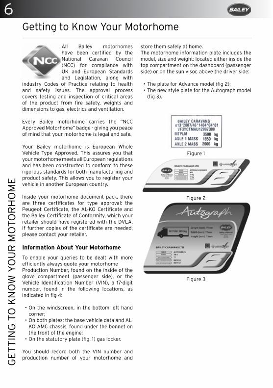
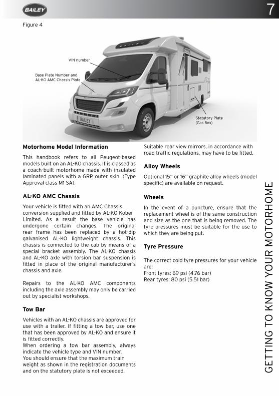
All Bailey motorhomes have been certified by the National Caravan Council (NCC) for compliance with UK and European Standards and Legislation, along with
industry Codes of Practice relating to health and safety issues. The approval process covers testing and inspection of critical areas of the product from fire safety, weights and dimensions to gas, electrics and ventilation.
Every Bailey motorhome carries the “NCC Approved Motorhome” badge - giving you peace of mind that your motorhome is legal and safe.
Your Bailey motorhome is European Whole Vehicle Type Approved. This assures you that your motorhome meets all European regulations and has been constructed to conform to these rigorous standards for both manufacturing and product safety. This allows you to register your vehicle in another European country.
Inside your motorhome document pack, there are three certificates for type approval: the Peugeot Certificate, the AL-KO Certificate and the Bailey Certificate of Conformity, which your retailer should have registered with the DVLA. If further copies of the certificate are needed, please contact your retailer.
Information About Your Motorhome
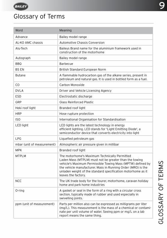
To enable your queries to be dealt with more efficiently always quote your motorhome Production Number, found on the inside of the glove compartment (passenger side), or the Vehicle Identification Number (VIN), a 17-digit number, found in the following locations, as indicated in fig 4:
• On the windscreen, in the bottom left hand corner;
• On both plates: the base vehicle data and AL-KO AMC chassis, found under the bonnet on the front of the engine;
• On the statutory plate (fig. 1) gas locker.
You should record both the VIN number and production number of your motorhome and
Figure 2
Figure 3
Figure 1
Getting to Know Your Motorhome
store them safely at home.The motorhome information plate includes the model, size and weight: located either inside the top compartment on the dashboard (passenger side) or on the sun visor, above the driver side:
• The plate for Advance model (fig 2); • The new style plate for the Autograph model
(fig 3).
7
GET
TIN
G T
O K
NO
W Y
OU
R M
OTO
RH
OM
E
Motorhome Model Information
This handbook refers to all Peugeot-based models built on an AL-KO chassis. It is classed as a coach-built motorhome made with insulated laminated panels with a GRP outer skin. (Type Approval class M1 SA).
AL-KO AMC Chassis
Your vehicle is fitted with an AMC Chassisconversion supplied and fitted by AL-KO KoberLimited. As a result the base vehicle has undergone certain changes. The original rear frame has been replaced by a hot-dip galvanised AL-KO lightweight chassis. This chassis is connected to the cab by means of a special bracket assembly. The AL-KO chassis and AL-KO axle with torsion bar suspension is fitted in place of the original manufacturer’s chassis and axle.
Repairs to the AL-KO AMC components including the axle assembly may only be carried out by specialist workshops.
Tow Bar
Vehicles with an AL-KO chassis are approved for use with a trailer. If fitting a tow bar, use one that has been approved by AL-KO and ensure it is fitted correctly. When ordering a tow bar assembly, always indicate the vehicle type and VIN number.You should ensure that the maximum trainweight as shown in the registration documents and on the statutory plate is not exceeded.
Suitable rear view mirrors, in accordance withroad traffic regulations, may have to be fitted.
Alloy Wheels
Optional 15” or 16” graphite alloy wheels (model specific) are available on request.
Wheels
In the event of a puncture, ensure that the replacement wheel is of the same construction and size as the one that is being removed. The tyre pressures must be suitable for the use to which they are being put.
Tyre Pressure
The correct cold tyre pressures for your vehicle are: Front tyres: 69 psi (4.76 bar)Rear tyres: 80 psi (5.51 bar)
VIN number
Base Plate Number and AL-KO AMC Chassis Plate
Statutory Plate(Gas Box)
Figure 4
9
GLO
SSA
RY
OF
TER
MS
Glossary of Terms
Word Meaning
Advance Bailey model range
AL-KO AMC chassis Automotive Chassis Conversion
Alu-Tech Baileys Brand name for the aluminium framework used in construction of the motorhome
Autograph Bailey model range
BBQ Barbecue
BS EN British Standard European Norm
Butane A flammable hydrocarbon gas of the alkane series, present in petroleum and natural gas. It is used in bottled form as a fuel.
CO Carbon Monoxide
DVLA Driver and Vehicle Licensing Agency
ESD Electrostatic discharge
GRP Glass Reinforced Plastic
Heki roof light Branded roof light
HRP Hose rupture protection
ISO International Organisation for Standardisation
LED light LED lights are the latest technology in energy efficient lighting. LED stands for 'Light Emitting Diode', a semiconductor device that converts electricity into light
LPG Liquefied petroleum gas
mbar (unit of measurement) Atmospheric air pressure given in millibar
MPK Branded roof light
MTPLM The motorhome's Maximum Technically Permitted Laden Mass (MTPLM) must not be greater than the towing vehicle's Maximum Permissible Towing Mass (MPTW) defined by the vehicle manufacturer. Mass in Running Order (MRO) is the unladen weight of the standard specification motorhome as it leaves the factory.
NCC The UK trade body for the tourer, motorhome, caravan holiday home and park home industries
O-ring A gasket or seal in the form of a ring with a circular cross section, typically made of rubber and used especially in swivelling joints.
ppm (unit of measurement) Parts per million also can be expressed as milligrams per liter (mg/L). This measurement is the mass of a chemical or contami- nate per unit volume of water. Seeing ppm or mg/L on a lab report means the same thing.

10G
LOSS
AR
Y O
F TE
RM
S Train weight The gross train weight is the weight of the fully-loaded
motorhome plus fully-loaded trailer and must not be exceeded. If your VIN plate doesn't list a train weight, you should not use your vehicle for towing.
UK United Kingdom
USB Universal Serial Bus type of connector
V (unit of measurement) Voltage - the difference in electric potential energy between two points per unit electric charge
VIN Vehicle Identification Number

Part of th
e Zen
ith P
rint G
rou
p
digital print large format printing
stationerym
ailing
lithographic printcorporate literature signage
banners
vehicle graphics canvas printsbuilding w
raps posters
pur/wiro binding personalisation M
anualsM
arketing material
C3
imag
ing
South
Wales
Un
it 13, Po
ntyfelin
Ind
ustrial E
stateN
ew In
n, P
on
typo
ol, N
P4
0D
Q
014
95
7676
80
enq
uiries@
c3im
agin
g.co
mw
ww
.c3im
agin
g.co
mW TE
Deliverin
g h
igh
qu
ality prin
t fo
r over 20 years…

12SA
FETY
AN
D S
ECU
RIT
Y
Safety and Security
Important Safety Notes ................................................................................................... 13
Security ............................................................................................................................... 13
Safety Equipment ............................................................................................................. 14
Smoke Alarm ..................................................................................................................... 14
Carbon Monoxide Alarm ................................................................................................. 14
13
SAFE
TY A
ND
SEC
UR
ITY
Safety and Security
Important Safety Notes
To ensure all the occupants of your motorhome enjoy a safe and relaxed environment please observe the following:
• Ensure all the occupants are aware of escape routes in the case of an emergency.
• Always keep escape routes and exit points clear from obstruction and debris.
• Provide one dry powder fire extinguisher of an approved type or complying with ISO 7465 of at least 1kg capacity by the main door, and a fire blanket next to the cooker. Familiarise yourself with your fire extinguisher and the local fire precaution arrangements.
• Your motorhome is a compact living environment, and appliances should be treated in the same way as those in the home to prevent any accidental burning or scalding – keep young children away from hot surfaces.
• Ensure the motorhome is serviced and maintained in accordance with this handbook as well as the base vehicle handbook. The recommendation of manufacturers regarding their appliances must also be followed. Also, ensure that any replacement parts for an appliance conform to the appliance manufacturer’s specifications and should be fitted by them or an authorised agent.
Before the vehicle is driven, please ensure that:
• Both the driver and passengers wear seat belts. This is a legal requirement.
• Heavy loads are not stored in top cupboards or in areas from which they may become detached. Please ensure that heavy items are stored low down and take care not to overload individual wheels, the axles or the MTPLM.
• Tables must be secured in their storage compartments.
• Cupboards and flaps are in the closed position and secured.
• The refrigerator door is closed and secured.• Roof ventilators are closed and locked in the
down position.• The bathroom is not used while the vehicle
is in motion. • Top hinged windows are closed and securely
fastened.• All passengers are secure and wear the
appropriate restraint for their height and age.
Security
WARNING: The theft of a motorhome can occur in the most unlikely circumstance; from a motorway area, even from an owner’s driveway.
Always remember to secure all windows and doors when your motorhome is unoccupied even if only for a short while.
Do not leave the handbook in the motorhome for extended periods of storage.
Consider fitting any device that may deter or prevent intrusion by thieves. A wheel lock prevents removal of the wheel.
Advice about securing your motorhome, protecting your valuables and property marking, either at home or while on site, can be obtained from your local Crime Prevention Officer through your local Police Station.
Additional security equipment is available from our website: www.bailey-parts.co.uk
14SA
FETY
AN
D S
ECU
RIT
Y
Safety Equipment
Smoke Alarm
The smoke alarm is operational once the battery is connected. When by-products of combustion are sensed, the unit sounds an alarm until the air is cleared.
Battery operation
The operating light (red LED) flashes every 40 seconds confirming that the unit is powered.
• Low Battery Warning: the unit will emit an audible “chirp” once every 40 seconds for 7 days before the battery needs to be replaced. Failure to replace the battery will result in insufficient power to alert you in a fire.
• Sensitivity test button: tests the circuitry, battery and horn.
Simple Maintenance
Your alarm requires one 9 volt battery. Under normal use, the battery should last one year.
• Test the smoke alarm after the vehicle has been in storage, before each trip and at least once a week during use.
• Clean your smoke alarm once every three months to help keep the unit working correctly; gently vacuum using the soft brush attachment.
Problems are indicated by two events:
• The alarm does not sound upon pressing the test button.
• The operating light remains steadily on or off (i.e. does not flash every 40 seconds, when the unit is not in alarm).
Try the following:
• Inspect for obvious damage.• Check that the unit contains recommended
battery type.• Check that the battery cover has been
removed.• Check that the battery is properly connected.• Gently vacuum as recommended above.• Replace battery.
If these procedures do not correct the problem, do NOT attempt repairs; replace the smoke alarm.
Carbon Monoxide Alarm
A CO-9B battery operated alarm is fitted near to the ceiling in your motorhome.
Features
• An advanced electrochemical sensor designed to accurately measure low levels of carbon monoxide (CO) providing an early warning of toxic CO levels in your motorhome.
• Detects carbon monoxide continuously.• Resistant to false alarms caused by usual
household contaminants.• Sounds a large 85dB alarm (at 1 metre (3
feet)) to alert you in case of an emergency.• Simple to mount, portable, ideal for travelling.• Conforms to the British Standards Institute
(CSi) Carbon Monoxide Standard BS EN 50291: 2001.
• 7 Year Warranty.• Test/Reset button feature.• Test the sounder, batteries and circuitry.• Allows you to test the sensor by introducing
a source of CO into the detector.• Silence the loud 85dB sounder during an
alarm (only possible when current CO level is less than 50ppm).
• Test the sounder, batteries and circuitry of your detector once per week by pressing and holding the Test/Reset button for 1 second to confirm that the detector is operating properly. The sounder should sound as soon as the button is pressed, and the alarm LED will illuminate red, indicating that the sounder is working and the batteries are providing power to the unit. The test for the sounder, batteries and circuitry should be performed weekly.
Testing the Sensor
All sensor testing should be carried out by a responsible adult. This test should only be performed once a month. Excessive testing will cause the battery life to be shortened.
NOTE: CO test kits may be used in order to avoid having to burn cigarettes, incense sticks etc.
Please read all steps thoroughly before attempting to test your alarm.
1. If the alarm is wall mounted, unhook the
15
SAFE
TY A
ND
SEC
UR
ITY
detector from the wall fixing screws.
2. Cover the sounder vents with one hand and hold the Test/Reset button down with your thumb/finger until the power LED illuminates green and the sounder sounds for a second time. (This should happen after 5 seconds). Release the Test/Reset button and the power LED will flash green once every second. This indicates that the sampling rate of the detector has increased and can be tested using a known source of CO.
3. Light an incense stick or a cigarette using a match or a lighter. If using an incense stick, be sure to blow the flame out so that the incense stick is smouldering. Extinguish the lighter, or put out the match and place it into a dish of water.
4. Turn the detector on its side so that the vents on the right hand side of the detector are pointing downwards. Hold the burning incense stick or cigarette around 15 cm (6 inches) below the detector, so that the smoke enters the vents on the side of the detector. An increase in the localised carbon monoxide level within the sensor to more than 50ppm will cause the sounder to sound for one cycle of four loud beeps and the Power LED to illuminate green for a short time. This is the end of the test. The Power LED will no longer flash green every second but will revert to flashing once every minute as the detector will go back to normal operating mode (it may take up to two minutes of exposure to the smoke for the localised level of carbon monoxide within the sensor to reach over 50ppm). Now move the source of CO away from the detector as the test is finished.
5. Put out the incense stick or cigarette by placing it into a dish of water. Ensure all flames have been extinguished.
NOTE: If the localised CO level within the sensor does not reach 50ppm during the test, the sensor test will stop automatically after 3 minutes.
Understanding your product’s indicators
The higher the concentration of carbon monoxide detected by the detector, the quicker it will respond. When sufficient carbon
monoxide is detected a loud audible signal (85dB at 1m/3ft) will be emitted and the alarm LED will flash red once every second.
The alarm will sound:
• Between 60 and 90 minutes when exposed to 50ppm of CO
• Between 10 and 40 minutes when exposed to 100ppm of CO
• Within 3 minutes when exposed to 300ppm or more.
Fault/low battery signal:
The unit continuously checks the settings of itssensor and circuitry. If any of these settingsare found to be incorrect or if the batteriesbecome low then the detector will emit asingle audible chirp once per minute for upto 30 days. This does NOT mean that the detector has detected carbon monoxide.
If the device continues to chirp despite having new batteries and the product is still in warranty then contact technical support for advice. If the device is no longer in warranty replace it immediately.
Maintaining/Testing Your Detector
Your detector will alert you to potential hazardous CO concentrations in your motorhome when maintained properly. To maintain your FireAngel detector in proper working order and to ensure that the sensor will last for the lifetime of the product, it is recommended that you:
• Test the sounder, batteries and circuitry of your detector once per week by pressing and holding the Test/Reset button for 1 second.
• Perform the sensor test annually.• Keep the detector free of dust by gently
vacuuming with a soft brush attachment when required.
To prevent the possibility of contaminating the sensor in your detector and thus affecting its reliability:
• Never use cleaning solutions on your detector. Simply wipe with a damp cloth.
• Do not paint the detector.• Do not spray aerosols on or near to the
16SA
FETY
AN
D S
ECU
RIT
Y
detector.• Do not use any solvent based products near
to the detector.
WARNING: Failure of any test should be reported to the manufacturer’s technical support line: 0800 1412561
Do not attempt to repair your CO detector. Do not remove any screws or open the main casing of your detector. Any attempt to do so may cause malfunction and will invalidate the warranty.
WARNING: Never ignore any alarm.
What to do in the event of an alarm
• Keep calm and open all the doors and windows to ventilate your motorhome.
• Stop using all fuel burning appliances and ensure where possible they are turned off.
• Evacuate the motorhome leaving doors and windows open.
• Do not re-enter the motorhome until the alarm has stopped.
• Get medical help for anyone suffering the effects of CO poisoning and advise that CO poisoning is suspected.
• Close the windows and doors and do not use the motorhome again until you have had a full service of all appliances by your supplying retailer. In the case of gas appliances they must be tested by a GAS SAFE registered installer. Please contact your Bailey retailer for more details.
• The electro-chemical sensors used in the carbon-monoxide alarm have a limited lifespan – therefore it is recommended that a CO alarm is replaced every 5 – 7 years after manufacture or in accordance with the unit’s instructions. Be sure check the manufacturing date on the alarm’s label.
17
WEI
GH
T R
ESTR
ICTI
ON
S A
ND
LO
AD
ING
Weight restrictions and loading
Loading And Distribution Of Weight In The Motorhome ......................................... 18
Mass In Running Order (MRO) ....................................................................................... 18
Maximum Technically Permissible Laden Mass (MTPLM): ...................................... 18
User Payload ...................................................................................................................... 18
Gross Train Mass (GTM) (sometimes referred to as GVW) ...................................... 19
Maximum Braked Trailer Mass (MBTM) ....................................................................... 19
Nose Weight ....................................................................................................................... 19
Advice On Towing ............................................................................................................. 19
When loading the trailer: ............................................................................................... 19
Axle Loads ......................................................................................................................... 20
Loading And Distribution Of Weight In The Motorhome ........................................ 20
Roof Loading ................................................................................................................... 20
Bike Rack Loading ........................................................................................................... 20
18W
EIG
HT
RES
TRIC
TIO
NS
AN
D L
OA
DIN
G
Weight restrictions and loading
Loading And Distribution Of Weight In The Motorhome
The driver is responsible for arranging items so that they comply with the technical weight limits of the specific motorhome model: refer to the Weight Data Table in your service manual.
Correct weight distribution is a major factor in making your motorhome a balanced and pleasant vehicle to drive without compromising road-holding. Care should therefore be taken to ensure that heavy items are well spaced and are in as low a position as possible, for example, low lockers and bed boxes. These larger/heavier items should be stored securely before travelling.
Do not travel with microwaves or televisions in overhead lockers unless the appliance was supplied fitted by the vehicle manufacturer.
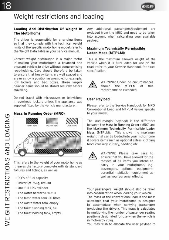
Mass In Running Order (MRO)
This refers to the weight of your motorhome as it leaves the factory complete with its standard fixtures and fittings, as well as:
• 90% of fuel capacity
• Driver (at 75kg, 11st2lb)
• One full LPG cylinder
• The water heater 90% full
• The fresh water tank 20 litres
• The waste water tank empty
• The toilet flushing tank, full
• The toilet holding tank, empty.
Any additional passengers/equipment are excluded from the MRO and need to be taken into account when calculating your available payload.
Maximum Technically Permissible Laden Mass (MTPLM):
This is the maximum allowed weight of the vehicle when it is fully laden for use on the road; refer to your Service Handbook for exact specification.
WARNING: Under no circumstances should the MTPLM of this motorhome be exceeded.
User Payload
Please refer to the Service Handbook for MRO, Conventional Load and MTPLM values specific to your model.
The load margin (payload) is the difference between the Mass in Running Order (MRO) and the Maximum Technically Permissible Laden Mass (MTPLM). This shows the maximum weight that can be loaded into your motorhome; it covers items such as optional extras, clothing, food, crockery, cutlery, bedding etc.
WARNING: Please take care to ensure that you have allowed for the masses of all items you intend to carry in your motorhome, e.g. passengers, optional equipment, essential habitation equipment as well as your personal effects.
Your passengers’ weight should also be taken into consideration when loading your vehicle.The mass of the conventional load is the mass allowance that your motorhome is designed to accomodate when carrying passengers (excluding the driver). This mass is calculated by multiplying the number of passenger seating positions designated for use when the vehicle is in motion by 75kg. You may wish to allocate the user payload to
HEAVY ITEMS MEDIUM ITEMS LIGHT ITEMS

19
WEI
GH
T R
ESTR
ICTI
ON
S A
ND
LO
AD
ING
suit your own use. For example, to increase the available payload, the water system may be emptied. If it is not being used, the gas cylinders can be left at home to increase the mass available for other items.
Gross Train Mass (GTM)
If you are towing a trailer with your Bailey motorhome the gross train mass is the MTPLM of the towing vehicle plus the trailer and the mass of every item carried. The GTM is specified by the base vehicle manufacturer (AL-KO) and is unaffected by the Bailey conversion.
Maximum Braked Trailer Mass (MBTM)
This is the maximum allowable weight of the trailer together with its load, provided the trailer has a braking system which complies with the local Construction and Use Regulations. The MBTM is given by the base vehicle manufacturer (AL-KO) and is unaffected by the Bailey conversion.
Nose Weight
This is the static mass of the trailer towing device on the rear of the towing vehicle.
• When measuring nose weight it is important that the trailer is loaded.
• The trailer is intended to be towed slightly nose heavy. The nose weight can be adjusted by redistribution of the load. The nose weight should be approximately 7% of the actual laden weight (but not greater than the hitch capacity) and at the same time suit the motorhome requirements
Advice On Towing
The towing specification alters depending on the vehicle’s weight; refer to ‘AL-KO AMC Chassis’ on page 7.When towing, the demands on both the driver and the vehicle are increased. Manoeuvrability is reduced together with the ability to climb gradients and accelerate. Braking and vehicle handling are also affected. Towing requires sensible loading of both the motorhome and the towed trailer.
• It is essential that the driver is alert at all times.
• Pull over if you feel tired and get some rest.
• Brake in good time and take special care when driving down steep gradients.
• Use your gears and change down before going down a steep hill so that the engine also acts as a brake.
• Ensure that the tyre pressures are correct on both your motorhome and the towed trailer.
• Regularly check the towed trailer’s brakes and lights.
When loading the trailer:
Ensure that the loads are properly secured for transit:
• Position loads so that most of the weight is placed close to the floor and, where possible, immediately above or close to the axle(s).
• Where the load can be divided between the towed trailer and the motorhome it is advisable to load more into the motorhome as this will greatly increase the stability of the combination.
• After loading always check the maximum weight does not exceed the manufacturer’s recommendations.
• Check the front and rear axle weights of the motorhome are not exceeded due to loading the trailer. The easiest way to do this is to take the vehicle to a weighbridge.
• Do not exceed the motorhome gross vehicle train weight.
• Do not exceed the maximum front and rear axle loads on the motorhome.
• Only tow bars complying with 94/20/EC should be fitted to the motorhome.
• The maximum permitted mass of an un-braked trailer is 750kg.
• The maximum permitted vehicle combination length is 18.75m. However, any combination must ensure compliance with the turning circle requirements of Construction and Use regulations 1986 and 97/27/EC.
20W
EIG
HT
RES
TRIC
TIO
NS
AN
D L
OA
DIN
G
NOTE: Towing regulations vary depending upon the country you are visiting. It is important that you make yourself aware of each country’s regulations before you visit.
Axle Loads
Individual axles have upper limits. The sum of the two axle upper limits usually exceeds the overall vehicle MTPLM, but this does not mean you can load each axle to its maximum, because doing so would exceed the overall MTPLM of the whole vehicle.
Loading And Distribution Of Weight In The Motorhome
Safely store tables, be it freestanding or fixed to the wall, into the dedicated storage compartment. Items fitted other than standard equipment will deplete the payload stated in the Service Handbook.
Roof Loading
Prior to fitting any type for roof mounted item please consult with your Bailey retailer to ensure the roof has the correct structural provisions to accept the item.Do not allow children to climb on the roof of your motorhome.Roof rack bars and ladders are an aftermarket option and if you are considering them, care should be taken to ensure that all items can be safely secured. Maximum load within the area encompassed by the roof rack should not exceed 75kg (165lb) with a maximum loading of 24kg per meter2 (8Kg (17lbs) per square foot.)
WARNING: Take special care when on the roof particularly in wet or frosty weather conditions, as the surface could be slippery. Always wear practical footwear when climbing onto your vehicle.
Bike Rack Loading
Your motorhome is fitted with bike rack rail fixing points. When fitting a bike rack check with the manufacturer that it is a motorhome approved rack and ensure that safety regulations and weight restrictions are adhered to.

PREMIUM ACCESSORIES FOR YOUR MOTORHOMEThe AL-KO premium motorhome accessories provide a complementary range of products designed to suit the AMC Chassis and your Bailey Motorhome.
The range now includes Cycle and Scooter Carriers, tow bars and steady legs, all designed to offer you more flexibility and enhanced comfort when using your motorhome.
For more information and to see the complete range of products, visit our website or email [email protected].
[email protected] | www.al-ko.co.uk
Scan with your smart phone to visit our website
22B
EFO
RE
MO
VIN
G O
FF
Before Moving Off
Whenever you plan to use your motorhome it is good practice to run through this simple check list before you set off:
• Ensure that there is sufficient gas to meet your needs.
• Check that gas cylinders are securely fastened.
• Turn off the gas supply, and all gas appliances - only leave gas on if your motorhome has a Truma MonoControl CS safety gas pressure regulator.
• Turn OFF all gas manifold taps (located under the sink).
• Ensure that the gas cylinder and locker door are securely fastened.
• Switch off the 230V supply at the site’s hook-up supply pillar; disconnect the mains cable from the vehicle. (Beware of a potential electric shock from a wet cable.) Coil cable and store in a safe place.
• Check both the control panel and the PDU box for operation.
• Check and, if necessary, charge your leisure battery. This can be viewed on your control panel.
• Check that the battery is secure and that the battery box door is securely fastened.
• Ensure that the fridge is set to 12V operation and the door lock is set. (Please note that the electrical relays will allow the fridge to run on the vehicle battery when the engine is running.)
• Ensure, if required, that your fresh water tank is full and your waste water tank is empty.
• Remove any external fresh water connections, coil and store in a secure place.
• Ensure that the toilet flush tank only contains a small amount of water (1–2 litres) in order to minimise the risk of leaks or spillage while the vehicle is in motion.
• Move the toilet blade handle to the closed position; refer to ‘Using The Toilet’ on page 141.
• Close and secure all cupboards and drawers and check for any loose articles.
• Do not store tins, jars, cylinders, etc in overhead lockers.
• Close and secure all windows and roof lights.
• Leave all curtains and blinds open.
• Make sure any heavy articles are stored in accordance with the loading procedure.
• Ensure tables are in their specified storage compartments.
• Lock the habitation door (remember to remove the keys).
• Check your wing mirrors and adjust if necessary.
• Check that the wheel bolts are secure and that the tyre pressures are correct.
• Check underneath the vehicle for any stray items.
• Safely store your levelling blocks away in an appropriate place.

24TR
AVEL
LIN
G
Travelling
Driving License ................................................................................................................. 25
Driving ................................................................................................................................ 25
Speed limits (UK) ............................................................................................................. 25
Front Seat Swivel ............................................................................................................. 26
Dedicated travelling passenger seating ..................................................................... 26
Seat Belt Legislation ....................................................................................................... 26
Child Seats - Positioning/Fitting ................................................................................. 26
Using the Seat Belts ........................................................................................................ 26
Airbag ................................................................................................................................. 26
Noise Vibration ................................................................................................................ 27
Removing the spare wheel ............................................................................................ 27
Jacking the motorhome ................................................................................................. 27
Changing front wheels ................................................................................................... 27
Changing rear wheels ..................................................................................................... 27
Spare Wheel Location - (Optional extra) .................................................................... 27
Returning the spare wheel to its compartment (Optional extra) ......................... 27
Fix and Go tyre repair ..................................................................................................... 28
25
TRAV
ELLI
NG
Driving License
Before you drive or allow any other person to drive your motorhome you must check your/their driving licence entitlements against the criteria of your particular vehicle. If your licence was issued before 1 January 1997 it may already include some higher categories.
WARNING: Never allow anyone without a valid driving licence to drive your motorhome.
Category B
With this category on your driving licence you can drive vehicles with a MTPLM of up to 3500Kg, with eight passenger seats, and with a trailer less than 750Kg. It’s also possible to tow a braked trailer heavier than 750Kg if the combined MTPLM and trailer are less than 3500Kg. The trailer must also be lighter than the vehicle towing it.To tow a trailer more than 750Kg than mentioned above you’ll need category B+E.
Category C1
With this category you can drive vehicles weighing between 3500Kg and 7500Kg (with a trailer up to 750Kg). To tow a heavier trailer you’ll need category C1+E.
Category C
With this category you can drive vehicles over 3500Kg (with a trailer up to 750Kg).
Category C+E
You can drive category C vehicles with a trailer over 750Kg.
Vehicle classificationsMotorhomes up to 3500Kg MTPLM are classed as P/LGV (Private Light Goods Vehicles); motorhomes with a MTPLM over 3500Kg and up to 7500Kg are classed as P/HGV (Private Heavy Goods Vehicles). These are normally used to define MOT classifications and vehicle excise duty (road tax) classifications. Please refer to the website: www.gov.uk/calulate-vehicle-tax-rates for the latest rules and regulations.
Driving
When using a motorhome on either the public highway or a private road, the Highway Code should be complied with and full consideration given to other road users.
In the event of a motorhome travelling slowly and there being a queue of traffic behind, the driver of the motorhome should, where possible, pull over in order to let the other traffic pass.
CAUTION: When the vehicle is in motion it is compulsory that all passengers are seated and seat restraints worn.
When the vehicle is being refuelled or is on a ferry, all gas systems must be turned off at the gas supply cylinder.
Speed limits (UK)
When a speed limit is in force, your motorhome can be driven up to 70 mph on motorways and 60 mph on dual carriageways. Due to it weighing more than 3.05 tonnes. Reduce Speed in high or cross winds, downhill or when visibility is poor.
• High sided vehicles cause air buffeting so extra care must be taken when passing or being passed. Leave as much space as possible when passing or being passed.
• When passing other vehicles allow more room than the normal clearance you would allow when driving a car.
• Allow longer to get up to speed and overtake.
• Do not swing out suddenly.
• Carry out all manoeuvres as smoothly as possible.
• Use wing mirrors to check that the motorhome has fully cleared a vehicle when overtaking.
Travelling
26TR
AVEL
LIN
G
Front Seat Swivel
The cab seats swivel for convenience when you are on site. However, when the vehicle is being driven they MUST be locked in their forward position.
Dedicated travelling passenger seating
Seat belts are fitted to all travelling seats.Designated travelling seats have been fitted to some layouts to ensure the safety of your passengers. These seats vary according to the layout that you have purchased. Each seatbelt frame is tested to the relevant safety requirements.
WARNING: NEVER travel in or attempt to install a seat belt to a non-designated seat.
Side-facing seats are for habitation use only, not for use when the vehicle is in motion.
Seat Belt Legislation
Seat belts must be worn when the vehicle is in motion by the driver and all adult passengers. In addition, children, aged under the age of 3 years of age, must wear an appropriate child restraint such as a child or booster seat suitable for their age and weight. Children over 135 cm (4’5”) in height or aged over 12 years must wear a seat belt. It is the legal responsibility of the driver to ensure children aged up to 14 years old are suitably restrained. For passengers aged 14 and over, it is their responsibility (not the driver’s).
Three point seat belts are located in the habitation compartment of your motorhome, fitted for you and your passenger’s safety - these must be worn, unless you have a ‘Certificate of Exemption from Compulsory Seat Belt Wearing’. This certificate must be produced if asked for by the police – seat belt offences may result in a fine.
Child Seats - Positioning/Fitting
Check with the retailer on the suitability of the child seat for your motorhome.
CAUTION: If a child seat is fitted to the front passenger seat of the cab, refer to the base vehicle handbook
(Peugeot) regarding the position and airbag operation. A warning sticker is visible inside the sun visor (passenger side) to remind you of this.
All of the motorhomes are fitted with inertia seat belts however, the child seat must be tight in the adult seat. Push all your weight into the child seat as you tighten the belt. Keep a copy of the child seat fitting instruction in the motorhome for easy reference.
Using the Seat Belts
• To fasten: insert the buckle into the plug-in socket until it clicks.
• To release: press the red release button; the buckle will be ejected from the plug-in socket.
• The belt is designed for one person and must not be put around a child seated on someone’s lap.
• It is suitable for retaining most child seats and boosters.
• It should always be used according to these instructions and adjusted accordingly.
• Never wear a slack seat belt.
• When installed correctly the seat belt should pass across the centre of the shoulder and fix into the plug-in socket beside the hip.
• It is important that the strap is not twisted during use as this can cause damage.
• Webbing must not be allowed to rub against sharp surfaces as this could lead to strap damage. If a belt is showing signs of wear (frayed, damaged or stressed) it should be replaced.
• Always replace a seat belt after an impact.
• Always check the anchorage points after an impact; if these are deformed the seatbelt frame will need to be replaced.
• Never modify the belt.
• Inspect your seat belt on a regular basis.
Airbag
For information about the airbag, check the base vehicle handbook.

27
TRAV
ELLI
NG
Noise Vibration
We understand that a quieter journey adds to your comfort as a traveller, so Bailey have used high density acoustic foam in the construction of your motorhome.
To help to reduce noise during transit:
• Store the Thetford grill pan and shelves in the storage compartment at the bottom of the oven. Wrap in a tea towel for further protection.
• Polyplastic Windows - the window stays on your motorhome have a tendency to rattle. We suggest that you tighten the stay and secure the catches, before you travel.
• Remis Cab Blinds - check that the cab blinds are fitted correctly. If they have become detached during transit please return your vehicle to your retailer and ask them to refit the blinds.
• The glass lid cover on the hob is also fitted with bump stops to prevent the glass from rattling on the trivet. Over a period of time, these bump stops may move from their ideal position. Reposition them or place a tea towel under the glass lid - please ensure that you remove the tea towel before you commence cooking.
Removing the spare wheel (Optional extra)
WARNING: Do not use the jack for loads that are greater than the load given on the jack rating plate. Ensure the vehicle is on a level, firm surface.
Jacking the motorhome
Position the jack in the hole provided as shown.Rear jacking points are located in the shockabsorber mounts on the left and right, in frontof the axle.When changing a rear wheel raise the vehicleto the maximum extent of the jack. In orderto clear the skirt when removing the wheel, tiltthe bottom of the wheel under the vehicle andallow the top of the wheel to fall outwards andclear of the hub.
Changing front wheels
Select first or reverse gear, apply the handbrake and chock the remaining wheel.
Onboard tools and chocks are usually locatedunderneath the passanger seat.
Changing rear wheels
Select first or reverse gear. DO NOT apply the handbrake but fit chocks under the remaining wheels.
Spare Wheel Location - (Optional extra)
The spare wheel is located at the rear underthe vehicle floor.
The spare wheel carrier fitted in your vehicle ismuch like that fitted into modern cars.
To lower the spare wheel:
1. Remove the plastic stopper in the floor. This is found inside the rear your motorhome. Directly above the wheel carrier.
2. Remove the winder from its storage location and insert the hooked end of the crank in the spare wheel retaining attachment.
3. Continue to lower the wheel by turning the crank anti-clockwise. Lower the wheel a little bit at a time and guide it until it is securely seated against the floor.
4. Draw the spare wheel towards you from under the vehicle.
5. Pivot the toggle at the end of the cable 90 deg to release it from the spare wheel.
As a safety precaution, have the flat tyrereplaced or repaired before fitting on the vehicle. When the spare wheel is being used on the vehicle, the retaining cable could damage the underside of the vehicle if not retracted. Crank up the cable again by turning the spare wheel retaining attachment clockwise. (The wheel with the flat tyre should be stored on the carrier for transport purposes.)
28TR
AVEL
LIN
G
Returning the spare wheel to the storage compartment (Optional extra)
1. Use the crank (turn it counter-clockwise)to lower the spare wheel’s retaining cable.When there is no wheel attached, the cablewill need to be gently pulled from thecarrier during lowering to ensure the cabledoes not tangle inside the carrier.
2. Pass the toggle at the end of the cablethrough the centre hole in the spare wheel. Pivot the toggle 90 deg so that whenraised, the wheel will rest on the toggle.
3. Retract the retaining cable slightly byslowly turning the crank clockwise severaltimes.
4. Position the wheel so that it is notobstructed by components under the floor.
5. Continue to raise the wheel by turning thecrank clockwise. Raise the wheel a little bitat a time and guide it until it is securelyseated against the floor.
6. When it is no longer possible to turn thecrank any further, check that the sparewheel is seated tight against the undersideof the floor and has not fouled on anycomponent.
7. Replace the plastic stopper inside thevehicle.
WARNING:
• The vehicle jack must only be used forchanging a wheel.
• Under no circumstances should anyone beallowed underneath the vehicle when it iselevated on a jack.
• On no account should it be used for repairwork under the vehicle. Never jack up thevehicle by the rear axle, front axle, oil sumpor transmission.
• When working on a loaded vehicle, use asuitable lift platform or inspection pit.
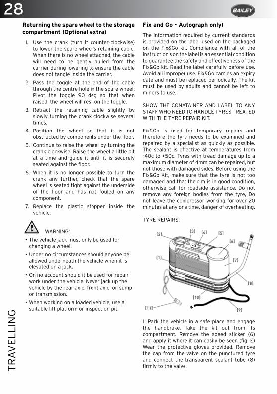
Fix and Go - Autograph only)
The information required by current standards is provided on the label used on the packaged on the Fix&Go kit. Compliance with all of the instruction s on the label is an essential condition to guarantee the safety and effectiveness of the Fix&Go kit. Read the label carefully before use. Avoid all improper use. Fix&Go carries an expiry date and must be replaced periodically. The kit must be used by adults and cannot be left to minors to use.
SHOW THE CONATAINER AND LABEL TO ANY STAFF WHO NEED TO HANDLE TYRES TREATED WITH THE TYRE REPAIR KIT.
Fix&Go is used for temporary repairs and therefore the tyre needs to be examined and repaired by a specialist as quickly as possible. The sealant is effective at temperatures from -40c to +50c. Tyres with tread damage up to amaximum diameter of 4mm can be repaired, but not those with damaged sides. Before using theFix&Go Kit, make sure that the tyre is not toodamaged and that the rim is in good condition,otherwise call for roadside assistance. Do notremove any foreign bodies from the tyre, Donot leave the compressor working for over 20minutes at any one time, danger of overheating.
TYRE REPAIRS:
1. Park the vehicle in a safe place and engagethe handbrake. Take the kit out from itscompartment. Remove the speed sticker (6)and apply it where it can easily be seen (fig. E)Wear the protective gloves provided. Removethe cap from the valve on the punctured tyreand connect the transparent sealant tube (8)firmly to the valve.
29
TRAV
ELLI
NG
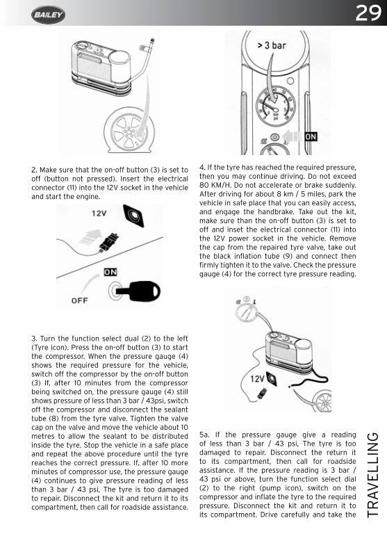
2. Make sure that the on-off button (3) is set to off (button not pressed). Insert the electrical connector (11) into the 12V socket in the vehicle and start the engine.
3. Turn the function select dual (2) to the left (Tyre icon). Press the on-off button (3) to start the compressor. When the pressure gauge (4) shows the required pressure for the vehicle, switch off the compressor by the on-off button (3) If, after 10 minutes from the compressor being switched on, the pressure gauge (4) still shows pressure of less than 3 bar / 43psi, switch off the compressor and disconnect the sealant tube (8) from the tyre valve. Tighten the valve cap on the valve and move the vehicle about 10 metres to allow the sealant to be distributed inside the tyre. Stop the vehicle in a safe place and repeat the above procedure until the tyre reaches the correct pressure. If, after 10 more minutes of compressor use, the pressure gauge (4) continues to give pressure reading of less than 3 bar / 43 psi, The tyre is too damaged to repair. Disconnect the kit and return it to its compartment, then call for roadside assistance.
4. If the tyre has reached the required pressure, then you may continue driving. Do not exceed 80 KM/H. Do not accelerate or brake suddenly. After driving for about 8 km / 5 miles, park the vehicle in safe place that you can easily access, and engage the handbrake. Take out the kit, make sure than the on-off button (3) is set to off and inset the electrical connector (11) into the 12V power socket in the vehicle. Remove the cap from the repaired tyre valve, take out the black inflation tube (9) and connect then firmly tighten it to the valve. Check the pressure gauge (4) for the correct tyre pressure reading.
5a. If the pressure gauge give a reading of less than 3 bar / 43 psi, The tyre is too damaged to repair. Disconnect the return it to its compartment, then call for roadside assistance. If the pressure reading is 3 bar / 43 psi or above, turn the function select dial (2) to the right (pump icon), switch on the compressor and inflate the tyre to the required pressure. Disconnect the kit and return it to its compartment. Drive carefully and take the
30TR
AVEL
LIN
G
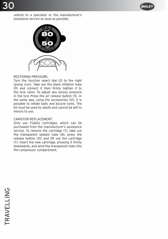
vehicle to a specialist or the manufacturer’s assistance service as soon as possible.
RESTORING PRESSURE:Turn the function select dial (2) to the right (pump icon). Take out the black inflation tube (9) and connect it then firmly tighten it to the tyre valve. To adjust any excess pressure in the tyre Press the air release button (5). In the same way, using the accessories (12), it is possible to inflate balls and bicycle tyres. The kit must be used by adults and cannot be left to minors to use.
CANISTOR REPLACEMENT:Only use Fix&Go cartridges, which can be purchased from the manufacturer’s assistance service. To remove the cartridge (7), take out the transparent sealant tube (8), press the release button (10) and lift out the cartridge (7). Insert the new cartridge, pressing it firmly downwards, and wind the transparent tube into the compressor compartment.
32SE
TTIN
G U
P O
N A
RR
IVA
L
Setting up on arrival
Siting Your Motorhome .................................................................................................. 33
Levelling Your Motorhome ............................................................................................ 33
Connect to Mains Electricity ......................................................................................... 33
Connect the Gas Supply ................................................................................................. 33
Fill up the Fresh Water Tank .......................................................................................... 34
Turning on the Heating .................................................................................................. 35
Powering your Fridge ...................................................................................................... 35
Connect your TV and Digital Antenna. ....................................................................... 35
33
SETT
ING
UP
UP
ON
AR
RIV
AL
Setting up upon arrival
The following are brief, but not exhaustive, instructions on how to initially set up your motorhome when you have arrived at your destination.
Report to reception for information about the site rules and carefully select where you wish to park your motorhome:
The site should be as level as possible, well drained and away from boggy areas, and preferably not under or near to trees.Consider how you will move your motorhome when you are leaving site; for example on sloping ground in wet conditions, pitch facing downhill.
Where possible leave 6 metres (20ft) of free space around your vehicle.
Levelling Your Motorhome
It is important to site your motorhome level so as to ensure the correct operation of the refrigeratior, cooker, microwave etc.Always use motorhome specific ramps rated for the weight of your vehicle.
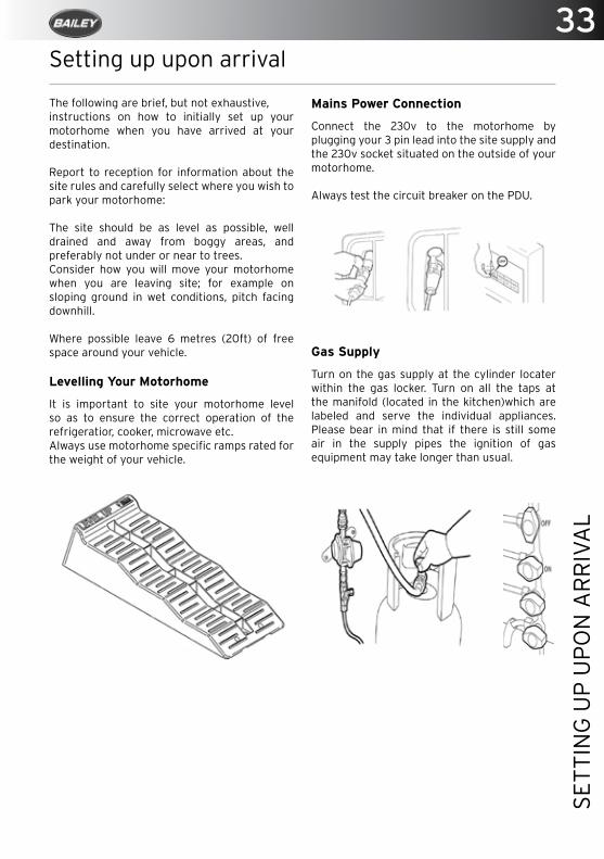
Mains Power Connection
Connect the 230v to the motorhome by plugging your 3 pin lead into the site supply and the 230v socket situated on the outside of your motorhome.
Always test the circuit breaker on the PDU.
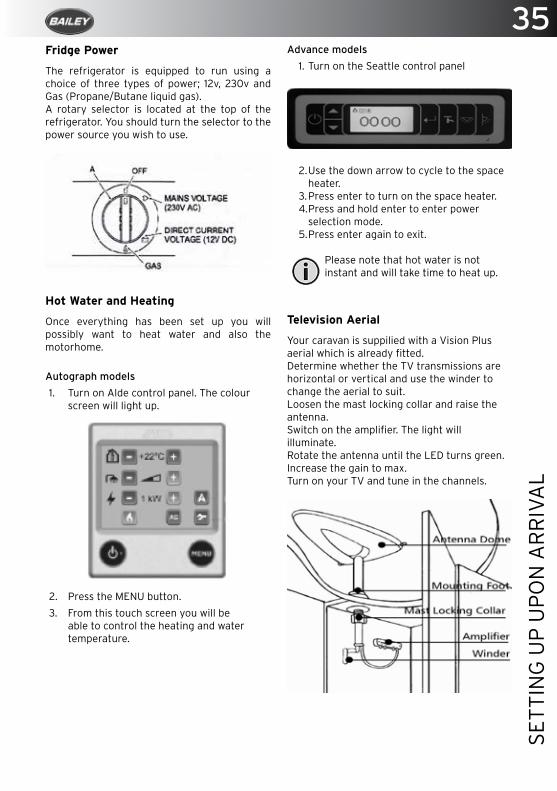
Gas Supply
Turn on the gas supply at the cylinder locater within the gas locker. Turn on all the taps at the manifold (located in the kitchen)which are labeled and serve the individual appliances. Please bear in mind that if there is still some air in the supply pipes the ignition of gas equipment may take longer than usual.

34SE
TTIN
G U
P U
PO
N A
RR
IVA
L Filling the fresh water tank
1. Close all taps.
2. Close drain valve located next to the water heater/boiler.
3. Autograph only - Fill the tank via an aqua roll and submersible pump plugged into the Whale pump inlet on the side of the motor home (Fig1). Alternatively remove the lid of the tank (Found underneath the hatch in the floor of your motorhome (Fig 2) using a standard hose.
4. Advance only - Locate the fresh water inlet found on the side of your motorhome. Remove the locking cap and use a standard hose to fill the tank via this inlet.
5. When in the fresh water tank screen on the control panel the percentage of fill is shown on the screen.
6. Once the tank is full.
7. Turn on the pump at your control panel. The light will come on when water is being pumped.
8. Open the hot kitchen tap and allow the system to purge itself of air until there is a steady flow of water. This will also fill the water heater ready for heating. Close kitchen tap.
9. Open the cold water tap and allow the system to purge itself of air until there is a steady flow of water.
10. Repeat operation for washroom.
Cassette Toilet
Withdraw the cassette and add the appropriate dose of chemical treatment along with 2-3 liters of water via the spout.
35
SETT
ING
UP
UP
ON
AR
RIV
AL
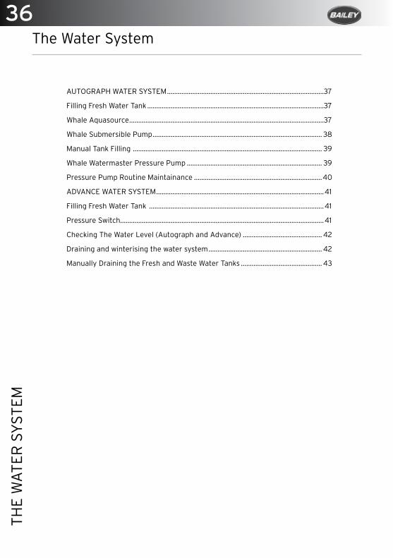
Fridge Power
The refrigerator is equipped to run using a choice of three types of power; 12v, 230v and Gas (Propane/Butane liquid gas).A rotary selector is located at the top of the refrigerator. You should turn the selector to the power source you wish to use.
Hot Water and Heating
Once everything has been set up you will possibly want to heat water and also the motorhome.
Autograph models
1. Turn on Alde control panel. The colour screen will light up.
2. Press the MENU button.
3. From this touch screen you will be able to control the heating and water temperature.
Advance models
1. Turn on the Seattle control panel
2. Use the down arrow to cycle to the space heater.
3. Press enter to turn on the space heater.4. Press and hold enter to enter power
selection mode.5. Press enter again to exit.
Please note that hot water is not instant and will take time to heat up.
Television Aerial
Your caravan is suppilied with a Vision Plus aerial which is already fitted. Determine whether the TV transmissions are horizontal or vertical and use the winder to change the aerial to suit.Loosen the mast locking collar and raise the antenna.Switch on the amplifier. The light will illuminate.Rotate the antenna until the LED turns green.Increase the gain to max.Turn on your TV and tune in the channels.
36TH
E W
ATE
R S
YST
EM
The Water System
AUTOGRAPH WATER SYSTEM .......................................................................................37
Filling Fresh Water Tank ..................................................................................................37
Whale Aquasource ............................................................................................................37
Whale Submersible Pump .............................................................................................. 38
Manual Tank Filling ......................................................................................................... 39
Whale Watermaster Pressure Pump ........................................................................... 39
Pressure Pump Routine Maintainance .......................................................................40
ADVANCE WATER SYSTEM .............................................................................................41
Filling Fresh Water Tank .................................................................................................41
Pressure Switch.................................................................................................................41
Checking The Water Level (Autograph and Advance) ............................................ 42
Draining and winterising the water system ............................................................... 42
Manually Draining the Fresh and Waste Water Tanks ............................................. 43
37
THE
WA
TER
SY
STEM
The Water System
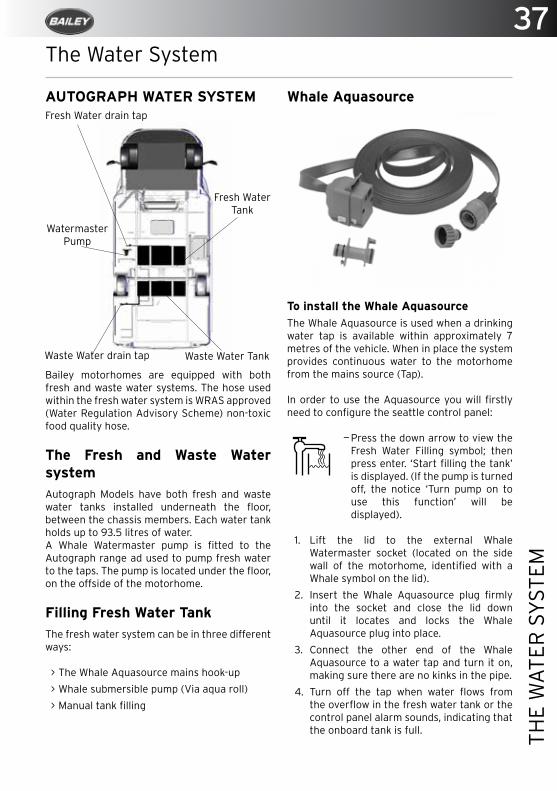
Bailey motorhomes are equipped with both fresh and waste water systems. The hose used within the fresh water system is WRAS approved (Water Regulation Advisory Scheme) non-toxic food quality hose.
The Fresh and Waste Water system Autograph Models have both fresh and waste water tanks installed underneath the floor, between the chassis members. Each water tank holds up to 93.5 litres of water. A Whale Watermaster pump is fitted to the Autograph range ad used to pump fresh water to the taps. The pump is located under the floor, on the offside of the motorhome.
Filling Fresh Water TankThe fresh water system can be in three different ways:
> The Whale Aquasource mains hook-up
> Whale submersible pump (Via aqua roll)
> Manual tank filling
Waste Water Tank
Fresh Water Tank
Watermaster Pump
Whale Aquasource
To install the Whale AquasourceThe Whale Aquasource is used when a drinking water tap is available within approximately 7 metres of the vehicle. When in place the system provides continuous water to the motorhome from the mains source (Tap).
In order to use the Aquasource you will firstly need to configure the seattle control panel:
—Press the down arrow to view the Fresh Water Filling symbol; then press enter. ‘Start filling the tank’ is displayed. (If the pump is turned off, the notice ‘Turn pump on to use this function’ will be displayed).
1. Lift the lid to the external Whale Watermaster socket (located on the side wall of the motorhome, identified with a Whale symbol on the lid).
2. Insert the Whale Aquasource plug firmly into the socket and close the lid down until it locates and locks the Whale Aquasource plug into place.
3. Connect the other end of the Whale Aquasource to a water tap and turn it on, making sure there are no kinks in the pipe.
4. Turn off the tap when water flows from the overflow in the fresh water tank or the control panel alarm sounds, indicating that the onboard tank is full.
Fresh Water drain tap
Waste Water drain tap
AUTOGRAPH WATER SYSTEM
38TH
E W
ATE
R S
YST
EM
To Remove the Whale Aquasource1. Disconnect the Whale Aquasource from
the tap.
2. Lift the lid of the Whale Watermaster socket to the vertical position.
3. Depress the two white location buttons on the Whale Watermaster plug and remove from the socket.
4. Close the lid of the Whale Watermaster socket.
5. Stow away the Whale Aquasource in a clean chemical-free area.
CAUTION: When you are using the Aquasource system it is important that you do not leave the vehicle unattended without turning the water source off at the supply point.
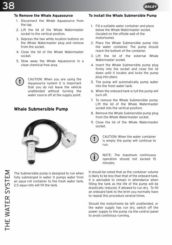
Whale Submersible Pump
The Submersible pump is designed to run when fully submerged in water. It pumps water from an aqua roll container to the fresh water tank, 2.5 aqua rolls will fill the tank.
To install the Whale Submersible Pump
1. Fill a suitable water container and place below the Whale Watermaster socket. (located on the offside wall of the motorhome).
2. Place the Whale Submersible pump into the water container. The pump should reach the bottom of the container.
3. Lift the lid of the external Whale Watermaster socket.
4. Insert the Whale Submersible pump plug firmly into the socket and close the lid down until it locates and locks the pump plug into place.
5. The pump will automatically pump water into the fresh water tank.
6. When the onboard tank is full the pump will turn off.
7. To remove the Whale Submersible pump. Lift the lid of the Whale Watermaster socket into the vertical position.
8. Remove the Whale Submersible pump plug from the Whale Watermaster socket.
9. Close the lid of the Whale Watermaster socket.
CAUTION: When the water container is empty the pump will continue to run.
NOTE: The maximum continuous operation should not exceed 15 minutes.
It should be noted that as the container volume is likely to be less than that of the onboard tank, it is advisable to remain in attendance when filling the tank as the life of the pump will be drastically reduced, if allowed to run dry. To fill an onboard tank to the brim you normally have to repeat this procedure several times.
Should the motorhome be left unattended, or the water supply has run dry, switch off the power supply to the pump via the control panel to avoid continious running.
39
THE
WA
TER
SY
STEM
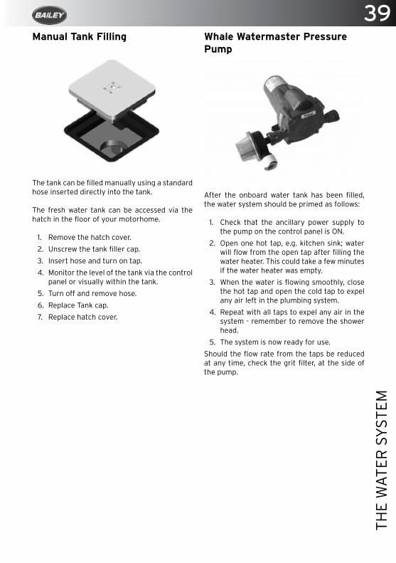
Manual Tank Filling
The tank can be filled manually using a standard hose inserted directly into the tank.
The fresh water tank can be accessed via the hatch in the floor of your motorhome.
1. Remove the hatch cover.
2. Unscrew the tank filler cap.
3. Insert hose and turn on tap.
4. Monitor the level of the tank via the control panel or visually within the tank.
5. Turn off and remove hose.
6. Replace Tank cap.
7. Replace hatch cover.
Whale Watermaster Pressure Pump
After the onboard water tank has been filled, the water system should be primed as follows:
1. Check that the ancillary power supply to the pump on the control panel is ON.
2. Open one hot tap, e.g. kitchen sink; water will flow from the open tap after filling the water heater. This could take a few minutes if the water heater was empty.
3. When the water is flowing smoothly, close the hot tap and open the cold tap to expel any air left in the plumbing system.
4. Repeat with all taps to expel any air in the system - remember to remove the shower head.
5. The system is now ready for use.
Should the flow rate from the taps be reduced at any time, check the grit filter, at the side of the pump.
40TH
E W
ATE
R S
YST
EM
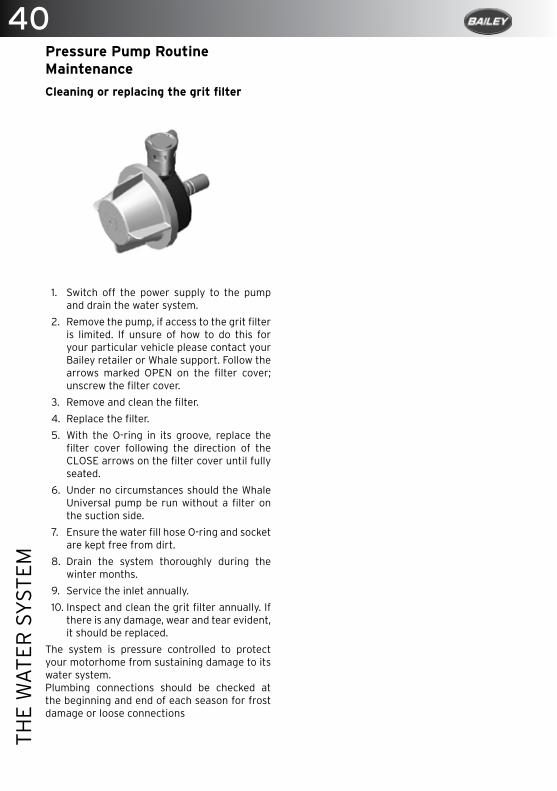
Pressure Pump Routine MaintenanceCleaning or replacing the grit filter
1. Switch off the power supply to the pump and drain the water system.
2. Remove the pump, if access to the grit filter is limited. If unsure of how to do this for your particular vehicle please contact your Bailey retailer or Whale support. Follow the arrows marked OPEN on the filter cover; unscrew the filter cover.
3. Remove and clean the filter.
4. Replace the filter.
5. With the O-ring in its groove, replace the filter cover following the direction of the CLOSE arrows on the filter cover until fully seated.
6. Under no circumstances should the Whale Universal pump be run without a filter on the suction side.
7. Ensure the water fill hose O-ring and socket are kept free from dirt.
8. Drain the system thoroughly during the winter months.
9. Service the inlet annually.
10. Inspect and clean the grit filter annually. If there is any damage, wear and tear evident, it should be replaced.
The system is pressure controlled to protect your motorhome from sustaining damage to its water system.Plumbing connections should be checked at the beginning and end of each season for frost damage or loose connections
41
THE
WA
TER
SY
STEM
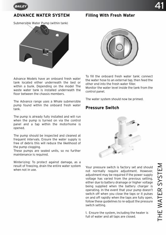
ADVANCE WATER SYSTEM
Advance Models have an onboard fresh water tank located either underneath the bed or within a bunk. Depending on the model The waste water tank is installed underneath the floor between the chassis members.
The Advance range uses a Whale submersible pump found within the onboard fresh water tank.
The pump is already fully installed and will run when the pump is turned on via the control panel and a tap within the motorhome is opened.
The pump should be inspected and cleaned at frequent intervals. Ensure the water supply is free of debris this will reduce the likelihood of the pump clogging. These pumps are sealed units, so no further maintenance is required.
Winterizing: To protect against damage, as a result of freezing, drain the entire water system when not in use.
Submersible Water Pump (within tank)
Filling With Fresh Water
To fill the onboard fresh water tank: connect the water hose to an external tap, then feed the other end into the fresh water filler.Monitor the water level inside the tank from the control panel.
The water system should now be primed.
Pressure Switch
Your pressure switch is factory set and should not normally require adjustment. However, adjustment may be required if the power supply voltage has varied from the previous setting, either due to battery drainage or higher voltage being supplied when the battery charger is operating. In the event that your pump doesn’t switch off when you close the taps or it pulses on and off rapidly when the taps are fully open, follow these guidelines to re-adjust the pressure switch setting.
1. Ensure the system, including the heater is full of water and all taps are closed.

42TH
E W
ATE
R S
YST
EM
2. Tighten the adjusting screw clockwise until the pump comes on. (For integral socket based pressure switches, first loosen the pressure switch locknut in an anti-clockwise direction). 3. Open any tap until you have a smooth flow of water, then close the tap. You should hear the pump running and the pump running light, if fitted, will be on.
4. Return to the pressure switch and turn the pressure switch adjustment screw slow anti-clockwise until the pump has stopped. Turn the screw a further half turn (180 degrees) anti-clockwise.
5. Check for correct operation by opening and closing all taps individually. The pump should turn on when the cold tap is opened and switch off immediately when the cold tap is closed. NB. There will normally be some pulsations at lower flows.
The hot side may take a few seconds to react (both on and off) due to cushioning effect in the water heater.
For integral socket based pressure switches, carefully tighten the locknut until it is right keeping the adjustment screw in position.
If setting of the pressure switch is still not correct you may experience:
> Pump running continuously, even with tap closed. If undiscovered, could result in pump failure and flat battery. Most likely causes are that present voltage is significantly lower when last adjusted, or water container is empty.
Solution: Re-adjust switch or refill container.
> Pump does not run at all. If not due to a blown fuse or faulty connections, then most likely cause is excessive running (see above)
Solution: Replace pump and re-adjust switch.
> Pump runs intermittently ON, OFF etc. Seen as pulsing flow from tap, or as inability to set constant water temperature, water goes hot, cold, hot, cold instead of constant warm. Most likely cause is that present voltage is higher than when last adjusted.
Solution: Re-adjust pressure switch if problem persists add a Whale Surge Damper (WS7205.)
> Pump runs very noisily but does not pump water. Likely to occur after water container has been refilled. Pump is air-locked and is fighting to get air out of and water in.
Solution: Unplug from the socket, allowing pump to flood, and reconnect by plugging in again. The correct sequence when refilling the container is to unplug put pump into container, then reconnect.
If after following these procedures the system continues to pulse when all taps are closed there may be a leak in the system.
To Check the Water Level (Both Autograph and Advance)
—Press the down arrow until you see the fresh water icon; The level is shown as a percentage.
—Press the down arrow until you see the waste water icon; The level is shown as a percentage.
Draining and winterising the Fresh water systemsMotorhomes are often used all year round but when they are not in use, even for short periods they should be drained down. One night in freezing temperatures is all that is required for expensive, permanent damage to occur to water system components.
Follow this procedure to prevent any damage:
1. Open all taps; lift the mixer tap levers in the central position to allow both the hot and cold water to drain.
2. Remove the shower head; unscrew by hand then shake out and store in a dry place.
3. Open the drain valve (to the side of the onboard tank in Advance models. To the side of the boiler on Autograph models). Then turn on the pump to drain the system.
43
THE
WA
TER
SY
STEM
Manually Draining the Fresh and Waste Water Tanks (Both Autograph and Advance)An inspection cap is positioned either on the top of the tank to allow access to the drain plug.
To drain the waste water tank move your vehicle to a waste water disposal point. Open the waste water drain tap (positioned behind the rear wheel on offside of the vehicle and allow the water to drain.
The manual drain plug for the Advance fresh water tank is accessed through the tank’s inspection hole. Located in the top of the tank.The plug is pulled from the bottom of the tank to drain the water.
The manual drain tap for the Autograph can be found behind the Whale watermaster pressure pump on the underside of your vehicle. Open the tap and allow the tank to drain.
NOTE: Manual draining should always be undertaken when winterising your vehicle to ensure a
full drain.
BreathersBoth tanks are fitted breather pipes. This allows for air displacement when filling. When filling the fresh water tank, water may escape through these breather pipes - this should give no cause for concern.
BafflesFor added stability and driving comfort the water tanks in your vehicle are fitted with baffles. These baffles stop the water from flowing freely from side to side, creating uneven weight distribution.
Frost ProtectionIf the vehicle is not being used during freezing conditions the water must be drained.
Frost damage cannot be claimed under warranty.

Upgrade to even more comfort on the move
www.trumauk.com
Experience the ultimate comfort of Automatic Climate Control (ACC) by upgrading your Approach Autograph II motorhome with the Truma Aventa Air Conditioner.
Your vehicles heating system and the Truma Aventa work perfectly together to keep you cosy in the winter and cool in the summer.
Set your preferred temperature just once and let the ACC system keep you in ultimate comfort.
Catch up with us onFacebook and Twitter
45
THE
GA
S SY
STEM
The Gas System
Types of Gas ......................................................................................................................46
Safe Use Of Gas Supply To Appliances .......................................................................46
Regulator ...........................................................................................................................46
Truma Monocontrol Cs Safety Gas Pressure Regulator - Autograph ................. 47
Gas System Maintenance ...............................................................................................48
Changing The LPG Cylinder .......................................................................................... 49
Cylinder Change ...............................................................................................................48
Hose Replacement...........................................................................................................48
Gas Leaks........................................................................................................................... 49
Ventilation ......................................................................................................................... 49
General Safety Notes ...................................................................................................... 49
Fire Precautions ...............................................................................................................50
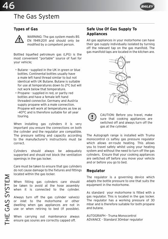
46TH
E G
AS
SYST
EM
The Gas System
Types of Gas
WARNING: The gas system meets BS EN 1949:2011 and should only be modified by a competent person.
Bottled liquefied petroleum gas (LPG) is the most convenient “portable” source of fuel for your vehicle;
• Butane - supplied in the UK in green or blue bottles. Continental bottles usually have a male left hand thread similar to but not identical with UK Butane. Butane is suitable for use at temperatures down to 2°C but will not work below that temperature.
• Propane - supplied in red, or partly red bottles and have a female left hand threaded connector. Germany and Austria supply propane with a male connection. Propane will work at temperatures as low as -40°C and is therefore suitable for all year touring.
When installing gas cylinders it is very important you ensure the connections on both the cylinder and the regulator are compatible. The pressure setting and capacity according to the manufacturer’s instructions must be correct.
Cylinders should always be adequately supported and should not block the ventilation openings in the gas locker.
Care must be taken to ensure that gas cylinders do not cause damage to the fixtures and fittings located within the gas locker. When fitting gas cylinders care should be taken to avoid at the hose assembly when it is connected to the cylinder. Always turn off the gas cylinder valve(s) or inlet to the motorhome or other dwelling when gas appliances are not in use or when retiring to bed (If possible). When carrying out maintenance always ensure gas soures are correctly capped off.
Safe Use Of Gas Supply To Appliances
All gas appliances in your motorhome can have their gas supply individually isolated by turning off the relevant tap on the gas manifold. The gas manifold taps are located in the kitchen are.
CAUTION: Before you travel, make sure that cooking appliances are switched off and always turn off the gas at the cylinder.
The Autograph range is installed with Truma monocontrol cs saftey gas pressure regulator which allows en-route heating. This allows you to travel safely whilst using your heating system and without the need to turn off the gas cylinders. Ensure that your cooking appliances are switched off before you move your vehicle and or before you go to bed.
Regulator
The regulator is a governing device which adapts the bottle pressure to one that suits the equipment in the motorhome.
As standard your motorhome is fitted with a gas regulator. This is located in the gas locker. The regulator has a working pressure of 30 mbar and is therefore suitable for both propane and butane.
AUTOGRAPH - Truma MonocontrolADVANCE - Standard 30mbar regulator

47
THE
GA
S SY
STEM
Truma Monocontrol Cs Safety Gas Pressure Regulator - Autograph Only
The Autograph range is fitted with a Truma MonoControl CS safety gas pressure regulator which can be found inside the gas locker. Only a high pressure gas hose with integrated hose rupture protection (HRP) should only be used to connect the gas cylinder to the gas pressure regulation system.
The integrated crash sensor complies with the Heating Equipment Directive 2001-56-EC with the supplements 2004-78-EC and 2006/119/EC.
The crash sensor enables you to use a liquid gas heater while driving, providing suitable precautions against an uncontrolled release due to an accidental disconnection. In the event of an accident (with deceleration of 3.5g with a tolerance of 0.5g acting directly upon the triggering element) the integrated crash sensor interrupts the flow of gas.
The gas system is certified for use throughout Europe. This includes use while the vehicle is being driven.
It is important that only upright gas cylinders are used when operating the MonoControl CS gas pressure regulation system. Gas cylinders from which gas is extracted in the liquid phase must not be used, since they would result in damage to the gas system.
If you suspect a gas leak then immediately turn off the supply of gas at the yellow isolation tap located below the regulator in the gas box. Then turn off the gas valve on the gas cylinders. When this has been completed the system must be inspected by a competent person.
Only use gas cylinders that are mounted in their dedicated storage locker and secured using the straps provided. Never use gas cylinders located outside the motorhome gas box.
WARNING: Never replace your regulator with one that does not conform to EN12864 Annex D as this does not comply with EN1949.
WARNING: Never extend the hose; IT MUST NOT EXCEED 450MM.
WARNING: The pressure regulating device and hoses must be replaced with new ones no more than 10 years after their date of manufacture (8 years if used commercially).
This is the responsibility of the owner.
WARNING: Do not use a regulator with a different operating pressure.
WARNING: In the case of a connection on a pressure regulator or gas appliance which relies upon a sealing washer to maintain a gas-tight joint, it is essential to check that the washer is present and that it is correctly positioned prior to making the connection. Where the connection relies on a metal to metal seating or bull nose connection to obtain a gas-tight joint it is essential that the mating surfaces are clean and undamaged. In no case should a damaged valve or connection be used.
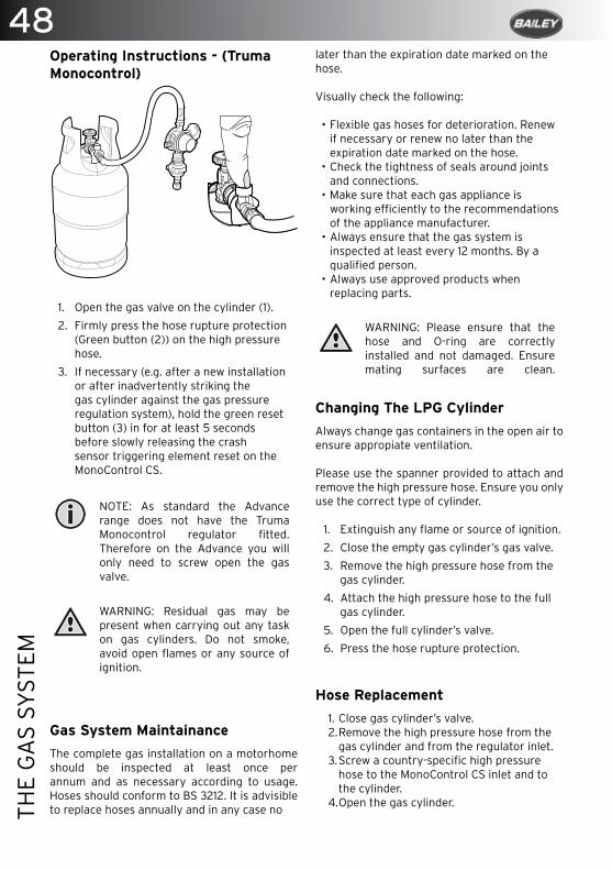
48TH
E G
AS
SYST
EM
Operating Instructions - (Truma Monocontrol)
1. Open the gas valve on the cylinder (1).
2. Firmly press the hose rupture protection (Green button (2)) on the high pressure hose.
3. If necessary (e.g. after a new installation or after inadvertently striking the gas cylinder against the gas pressure regulation system), hold the green reset button (3) in for at least 5 seconds before slowly releasing the crash sensor triggering element reset on the MonoControl CS.
NOTE: As standard the Advance range does not have the Truma Monocontrol regulator fitted. Therefore on the Advance you will only need to screw open the gas valve.
WARNING: Residual gas may be present when carrying out any task on gas cylinders. Do not smoke, avoid open flames or any source of ignition.
Gas System Maintainance
The complete gas installation on a motorhome should be inspected at least once per annum and as necessary according to usage. Hoses should conform to BS 3212. It is advisible to replace hoses annually and in any case no
later than the expiration date marked on thehose.
Visually check the following:
• Flexible gas hoses for deterioration. Renew if necessary or renew no later than the expiration date marked on the hose.
• Check the tightness of seals around joints and connections.
• Make sure that each gas appliance is working efficiently to the recommendations of the appliance manufacturer.
• Always ensure that the gas system is inspected at least every 12 months. By a qualified person.
• Always use approved products when replacing parts.
WARNING: Please ensure that the hose and O-ring are correctly installed and not damaged. Ensure mating surfaces are clean.
Changing The LPG Cylinder
Always change gas containers in the open air to ensure appropiate ventilation.
Please use the spanner provided to attach and remove the high pressure hose. Ensure you only use the correct type of cylinder.
1. Extinguish any flame or source of ignition.
2. Close the empty gas cylinder’s gas valve.
3. Remove the high pressure hose from the gas cylinder.
4. Attach the high pressure hose to the full gas cylinder.
5. Open the full cylinder’s valve.
6. Press the hose rupture protection.
Hose Replacement
1. Close gas cylinder’s valve.2. Remove the high pressure hose from the
gas cylinder and from the regulator inlet.3. Screw a country-specific high pressure
hose to the MonoControl CS inlet and to the cylinder.
4. Open the gas cylinder.
49
THE
GA
S SY
STEM
5. Press the hose rupture protection and, if necessary, the reset button.
6. Check the hose connection to the cylinder valve and at the MonoControl CS inlet for leaks after every modification.
7. After making changes always check the connection to the cylinder for leaks using a leak detector spray or a soapy solution.
NOTE: We recommend that the gasket (part number 50020-76300) is replaced with every hose change. This will be provided by your supplying dealer upon replacement of the hose.
Gas Leaks
If a smell of gas becomes apparent, the supply should be turned off at the cylinder immediately. Extinguish all naked flames/sources of ignotion.
• Ensure the gas valve is turned off. • The strong unpleasant smell of gas means
that a leak has been detected. • Check that gas is not escaping from an unlit
appliance.• Never check for leaks with a naked flame.
Check all pipe joints by using a washing up liquid solution – the gas will bubble in the area of the leak. Isolate the supply, preferably at the cylinder, and seek professional help.
• Do not operate electrical switches. • Open all doors and windows to allow any gas
to escape. Butane/propane gas is heavier than air so any escaping gas will therefore collect at a low level - ensure floor vents remain unobstructed.
• If the leak was internal, evacuate. • Check that gas is not escaping from an unlit
appliance. • If the gas leak cannot be stopped, remove
the cylinder to a safe place in the open air in an upright position away from drains and any source of ignition. Immediatly contact a competent service engineer.
• When being stored always keep gas cylinders outside (and protected against frost). If they must be kept inside make sure they are well away from heat and near to a drop vent.
• If taps are too stiff to operate or appear to
be a source of leakage, call in a competent installer to rectify. LPG taps require a special grease.
• If in doubt always seek the advice of a qualified engineer.
Ventilation
Carbon monoxide is odourless, colourless and tasteless and will rapidly cause unconsciousness and death with little or no warning prior to collapse. Under no circumstances should the motorhome’s ventilation be blocked or obstructed in any way. High level ventilation is via the rooflights. The low level ventilation is achieved via the vents located in the floor..
The exterior gas vent/flue should be kept free of any obstructions including but not limited to dust, leaves, dirt, personl items etc. Inspect regularly. Use a brush and soapy water to clean when needed. It may be necessary to remove the weather shield to gain access for cleaning.
WARNING: Safety ventilation shall in no circumstances be obstructed, even partially.
WARNING: Flues which terminate below the floor require that free evacuation of the products of combustion is always maintained. At least three sides of the underfloor space shall always be kept open and unobstructed especially by snow. No additional opening in the floor should be created.
General Safety Notes
The pressure of external LPG supply to external supply plug in’s shall not be less than 0,3 bar and not greater than 0,5 bar.
The operating pressure for the gas supply is 30mbar (or 28mbar butane/ 37mbar propane) and must correspond to the operating pressure of the appliance (see name plate).
During initial operation of a brand new appliance a certain amount of fumes and a slight smell may be noticed. Immediately run the heater at maximum output and to ensure adequate room ventilation.
50TH
E G
AS
SYST
EM
If the burner makes an unusual noise, it is likely that the regulator is faulty and it is essential to have it checked by a qualified person.Repair jobs must only to be carried out by a fully trained expert.
All flue installations should be inspected, at least once a year, throughout their length for integrity of attachment, both to appliance and cowl, and for perforation due to damage or corrosion. Flues should be replaced if any sign of damage or perforation is found. It should be ensured that the replacement is of an approved type conforming to the recommendations of BS 5440-1.
Gas cylinders can have different connections. It is important to check that you have the correct hose and or adaptor to suit your gas cylinder. Regulations no longer permit Push fit hoses. for further advice contact your motorhome retailer.
Gas cylinders that are not connected to the gas installation must be closed off at all times and fitted with protective caps.
onnections designed to be tightened with a spanner it is essential that a spanner of the correct size is used and that the union is firmly tightened: hand tightness is not sufficient. When self sealing valves are incorporated in a gas cylinder, connections should be made in accordance with the manufacturer’s instructions and tools should not be used.
CAUTION: Never use portable cooking or heating appliances, other than electric heaters that are not direct radiant type . They are a fire and asphyxiation hazard. Cookers should never be used as a heating source.
WARNING: Some industrial LPG appliances operate at high pressure and require a “high pressure” regulator. This often has an adjusting handle on it. NEVER USE SUCH A REGULATOR ON A MOTORHOME.
WARNING: Additional independent gas appliances should NOT be used inside the motorhome.
WARNING: Do not operate the water heater when refuelling the vehicle and when in the fuel station.
Where connections are designed to be tightened with a spanner it is essential that a spanner of the correct size is used and that the union is firmly tightened: hand tightness is not sufficient. When self sealing valves are incorporated in a gas cylinder, connections should be made in accordance with the manufacturer’s instructions and tools should not be used.
Fire Precautions
As stated in the introduction, a fire extinguisher is not provided with your motorhome therefore it is recommended that one is purchased of adequate size: it is recommended that a dry powder extinguisher is used, only if it is likely that the leakage can be stopped by closing the cylinder valve or that the cylinder can be removed quickly.
Cool with water all gas cylinders which cannot be removed. As soon as possible, remove any cylinders adjacent to the fire to a safe place in order to gain access to the seat of the fire.
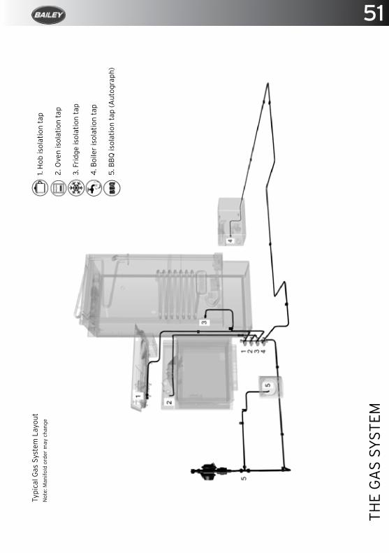
51
THE
GA
S SY
STEM
1. H
ob is
olat
ion
tap
2. O
ven
isol
atio
n ta
p
3. F
ridg
e is
olat
ion
tap
4. B
oile
r is
olat
ion
tap
5. B
BQ
isol
atio
n ta
p (A
utog
raph
)
Typi
cal G
as S
yste
m L
ayou
tN
ote:
Man
ifold
ord
er m
ay c
hang
e
52TH
E EL
ECTR
ICA
L SY
STEM
The Electrical System
The 230 Volt Electrical System .................................................................................... 53
Power Distribution Unit .................................................................................................. 53
The 12 Volt Electrical System ........................................................................................54
Upon Arrival A Motorhome Site ...................................................................................54
Leaving The Motorhome Site ........................................................................................54
Generators .........................................................................................................................54
Over Seas Connections .................................................................................................. 55
Leisure Battery..................................................................................................................56
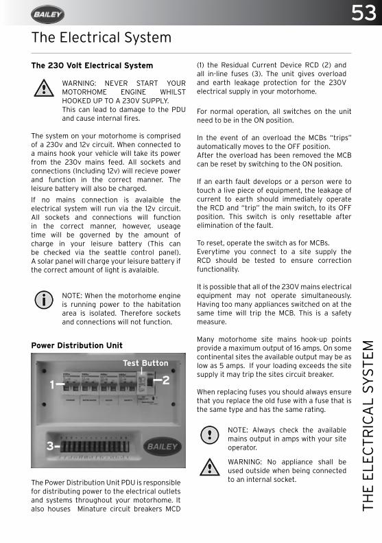
53
THE
ELEC
TRIC
AL
SYST
EM
The Electrical System
The 230 Volt Electrical System
WARNING: NEVER START YOUR MOTORHOME ENGINE WHILST HOOKED UP TO A 230V SUPPLY. This can lead to damage to the PDU and cause internal fires.
The system on your motorhome is comprised of a 230v and 12v circuit. When connected to a mains hook your vehicle will take its power from the 230v mains feed. All sockets and connections (Including 12v) will recieve power and function in the correct manner. The leisure battery will also be charged.
If no mains connection is avalaible the electrical system will run via the 12v circuit. All sockets and connections will function in the correct manner, however, useage time will be governed by the amount of charge in your leisure battery (This can be checked via the seattle control panel). A solar panel will charge your leisure battery if the correct amount of light is avalaible.
NOTE: When the motorhome engine is running power to the habitation area is isolated. Therefore sockets and connections will not function.
Power Distribution Unit
The Power Distribution Unit PDU is responsible for distributing power to the electrical outlets and systems throughout your motorhome. It also houses Minature circuit breakers MCD
(1) the Residual Current Device RCD (2) and all in-line fuses (3). The unit gives overload and earth leakage protection for the 230V electrical supply in your motorhome.
For normal operation, all switches on the unit need to be in the ON position.
In the event of an overload the MCBs “trips” automatically moves to the OFF position.After the overload has been removed the MCB can be reset by switching to the ON position.
If an earth fault develops or a person were to touch a live piece of equipment, the leakage of current to earth should immediately operate the RCD and “trip” the main switch, to its OFF position. This switch is only resettable after elimination of the fault.
To reset, operate the switch as for MCBs.Everytime you connect to a site supply the RCD should be tested to ensure correction functionality.
It is possible that all of the 230V mains electrical equipment may not operate simultaneously. Having too many appliances switched on at the same time will trip the MCB. This is a safety measure.
Many motorhome site mains hook-up points provide a maximum output of 16 amps. On some continental sites the available output may be as low as 5 amps. If your loading exceeds the site supply it may trip the sites circuit breaker.
When replacing fuses you should always ensure that you replace the old fuse with a fuse that is the same type and has the same rating.
NOTE: Always check the available mains output in amps with your site operator.
WARNING: No appliance shall be used outside when being connected to an internal socket.
1 2
3
Test Button
54TH
E EL
ECTR
ICA
L SY
STEM
The 12 Volt Electrical System
Your motorhome is fitted with a dual stage power supply/charger supplying 14.2V to your leisure battery and between 13.6/13.8V to the habitation area. This converts the 230V AC supply to 12V DC. It enables the 12V equipment in the motorhome to function and also charges the motorhome leisure battery. A fully charged leisure battery should read 12.7V on the voltmeter in the control panel. During charging the control panel will temporarily read between 14.2/13.8V.
The charger is capable of charging leisure batteries and will not overcharge. The 12V system is designed to operate with a leisure battery in circuit and should not be turned on without one connected. The 12V supply to the Motorhome services can be isolated via the 12V on/off switch on the control panel.The 12V electrical system’s fuses are located either in a bed box or under the fixed bed. It has 14 fuses, each having identification to their particular use. If a fuse is to be replaced it must be with one of the same rating as the one that is removed.
Upon Arrival At A Motorhome Site
1. Ensure the mains supply is suitable for your electrical installation and appliances. Check the current, voltage, frequency and polarity are correct.
2. Ensure the electrical installation will be properly earthed when connected. Never accept a supply from a socket outlet or plug thats lacks a proper earth.
3. Check that any Residual Current Device (RCD) within the Power Distrubution Unit (PDU) has been tested within the last month. (To test, follow steps 4 to step 9).
4. Make sure the switch at the site supply point is off.
5. Make sure the RCD is switched off.
6. Lift lid of the electricity inlet on the motorhome and insert the mains site lead. (The 230V mains inlet is located on the side of the motorhome and is identified by a lightning bolt).
7. Remove the cover from the socket outlet provided at the site and insert the mains site lead plug.
8. Turn on the site supply point. (If there is no switch the power will already be live.)
9. Coil excess cable in loose coils on the floor, not on a drum or in a container.
10. Switch on the motorhome RCD. Press the test button - the RCD should switch off breaking the circuit - this indicates RCD is functioning correctly.
11. Move the RCD switch to the on position.
12. In any case of doubt, consult the site owner or their agent.
13. Interior outlet sockets must only be used with approved appliances.
14. Only use suitable appliances externally.
Leaving The Motorhome Site
1. Switch off the site supply.
2. Switch off the motorhome RCD, then disconnect the supplied flexible cable.
3. Switch off and disconnect all portable appliances.
4. Stow mains site lead in a tidy state.
5. In any case of difficulty consult an approved electrical installation contractor. It is dangerous to attempt modifications yourself and may invalidate your warranty.
6. Lamp-holder plugs (bayonet-cap adapters) should not in any circumstances be used as a source of power.
7. Replace the cover of the socket outlet at the site supply point. It is dangerous to leave the supply socket or supply flexible cable live.
8. Every 12 months, the motorhome electrical installation should be inspected and tested. A report on its condition should be obtained as prescribed in the Regulations for Electrical Installations, published by the Institute of Electrical Engineers.
Generators
1. Switch off all appliances, all circuit breakers and RCD.
2. Start the generator and allow to run for a few minutes to stabilise.
3. Connect the motorhome to the generator using an approved mains site lead.
4. Switch on 16amp circuit breaker.
55
THE
ELEC
TRIC
AL
SYST
EM
5. Switch on the RCD.
6. Switch on the fridge (230V phase) or plug in a 230V light to one of the 13amp sockets. This is to provide a load on the generator and help remove any “spikes” in the supply which can damage the charger unit.
7. Switch on the 5 amp circuit breaker and any other appliances you require.
It is always advisable to have at least one other mains appliance switched on with the charger unit to minimise the chance of damage to it.
CAUTION: Do not connect the 12V output of the generator to the battery terminals.
CAUTION: The AC ripple must not exceed 10%.
Overseas Connections
CAUTION: Connection to a mains voltage supply overseas requires particular attention.
Care must be taken when connecting to a supply abroad as the supply may have reverse polarity. Reverse polarity can lead to safety issues due to the fact when electrical equipment is switched off it may not be electrically isolated. The only certain way of making equipment safe is to unplug it.
Motorhome Service Systems
A means of checking the polarity of the mains supply when overseas is useful. There are several proprietary makes of equipment available for this purpose. These can be found at www.bailey-parts.co.uk
The Leisure Battery
The leisure battery(s) is located under the floor in the motorhome in a sealed compartment. The Autograph compartment will accommodate two batteries up to 110 amperes/hours capacity. The Advance compartment accomodates one battery of up to 110 amperes/ hours capacity. The battery must be placed in the tray provided in the battery storage compartment, and this must be used at all times. A battery of not less than 60 amperes/hours capacity is recommended.
• The battery should be secured to prevent movement when in transit.
• Metal objects should not be stored in the battery box.
• DIY modifications/additions to the wiring systems are not recommended. Consult your dealer who will be pleased to carry out such work.
• Switch off all appliances before disconnecting battery.
• Negative connections should always be disconnected first and reconnected last.
• Car type battery chargers are not suitable for charging a leisure battery and may damage it.
• When not using motorhome models always ensure that the fridge control knob is turned to the “off” position. Failure to do this will result in a flat battery due to 12V power drain from the fridge circuit relays.
• Crocodile clips should never be used to connect the battery, and terminals should be shrouded.
• Any replacement of an auxiliary battery shall be of the same type and specification as that originally fitted battery or as specified by the manufacturer.
CAUTION: Always switch off all appliances and lighting before disconnecting the auxiliary battery.
56TH
E EL
ECTR
ICA
L SY
STEM
Banner Leisure Battery
Bailey has chosen to fit a Banner battery to your motorhome. These batteries are designed to cope with today’s increased energy demands. By choosing Banner we are assured of a first class product, fit for purpose, supplied by a leading European battery manufacturer. Banner possesses the latest ISO9001, ISO/TS 1649 and ISO 14001 quality certification.
Your Banner battery is 100% maintenance-free, which means under normal circumstances no maintenance is necessary. However, if there is a problem with the charging you will be able to check the acid levels through the outer casing. If they have dropped below the height of the plates, add distilled water.
CAUTION: Never overcharge your battery. A maximum voltage of 14.7V boost & 13.8V float should be used.
Battery Maintenance
• Wear goggles when working with the battery.
• Keep out of reach of children.• Keep away from naked flames.• Dispose of old batteries at an authorised
collection point. For a replacement unit please contact Bailey-Parts.co.uk
• The battery must always be kept upright without any danger of tipping. However, your Banner battery has 4 chamber leak protection so should not leak during normal handling.
• Prior to removal of the battery switch off all electrical systems.
• When removing the battery always remove the negative terminal first.
• Always ensure that the battery’s tray is clean.
• Never use a frozen battery or a battery in a temperature above 45° or warm to the touch.
• Stop using the battery if it becomes hot or acid escapes.
Taking out of operation
• Store in a cool dry place. Never store a flat or discharged battery. Always charge before storage and monitor voltage.
• Check the battery voltage every 4 months and recharge with a suitable battery charger if it has fallen below 12.5V.
• If the battery is left in the vehicle during storage, disconnect the negative terminal.
• For long periods of storage or non-use connect the battery to a suitable long term connection charger with a float mode such as an Optimate 5 or 6.

Banner-A5-Bailey-Ad.indd 1 18/07/2016 18:06

58TR
UM
A S
OLA
R D
UA
L B
ATT
ERY
CH
AR
GER
Truma Solar Dual Battery Charger
Introduction ...................................................................................................................... 59
Function ............................................................................................................................. 59
The Charging Process Explained ................................................................................. 59
Operation ...........................................................................................................................60
Safety Instructions .......................................................................................................... 62
Maintenance...................................................................................................................... 62
Repairs ............................................................................................................................... 62
Battery Care ...................................................................................................................... 62
Disposal .............................................................................................................................. 62
Technical Data .................................................................................................................. 63
59
TRU
MA
SO
LAR
DU
AL
BA
TTER
Y C
HA
RG
ER
Truma Solar Dual Battery Charger
Introduction
The solar module/panel generates power when light is cast upon it. The full voltage is also available even if there is little light. The solar automatic charger only serves to charge 12v (24v) lead accumulators comprising 6 (12) single cells with a capacity of 50-100Ah (SDC 10) or 50-200Ah (SDC 20) (e.g. leisure battery). The preferred application fields for the automatic charger are batteries with gel, AGM (Absorbed Glass Mat) or liquid electrolyte.
Function
The device has a modern microprocessor-controlled pulse width modulated three phase charging characteristic. This allows high performance combined with a light weight andsmall dimensions. By virtue of the high-quality electronics, it works highly efficiently. The automatic charging process preserves the device and does not overcharge the batteries. This in turn extends the service life of the batteries significantly. It is suitable for batteries with liquid, gel or AGM technology and has a settable charging current distribution for two separate battery connections. The device is designed for continuous operation and parallel mode. Consumers can be continuously connected, switched on or disconnected. Consumers are supplied and the batteries are charged at the same time. The consumer current here should be smaller than the solar charging current as otherwise the battery will not charge. If the device is operated in conjunction with an external temperature sensor for the supply battery (battery 1), the device regulates the charging voltage automatically depending on the battery temperature. This ensures particularly effective and gentle charging of the battery. If an external temperature sensor is not used, the device regulates the charging process based on the internal temperature sensor.
The leisure and starter batteries can be charged by connecting one or several solar modules.
CAUTIONS: Please observe the maximum voltage and power consumption values.
The Charging process Explained
The device has an electronic reverse voltage, reverse current and solar short-circuit protection. The charging current is only released (see “charging diagram”) if the battery is connected correctly and there is enough power available from sunlight.When a temperature sensor is used, charging takes place on a temperature-dependent basis.
Bulk phase
Charging with maximum available solar charging current until the charging end voltage is reached.
Absorption phase
The charging current is kept for a period of 2 hours. At the end of this period, it changes to the float phase.
Float phase
The charging voltage is set to 13.8 V. The charging current drops to the value necessary to compensate the self-consumption of the battery. Power is still supplied to the consumers. If the consumed current exceeds the available solar charging current, the charging process can no longer be maintained. If the battery voltage drops below 13.3 V, the device automatically switches to the bulk phase, if there is adequate solar charging current.
Equalisation charging phase
NOTE: Only for AGM and liquid electrolyte battery type
The equalisation charging phase serves to compensate the cell voltages and can reduce any sulphation. If the voltage of the battery drops below 11.1 V, it is assumed that the battery has deep-discharged. The device is switched to the equalisation charging phase for two hours. At the end of this period, it changes automatically to the float phase.
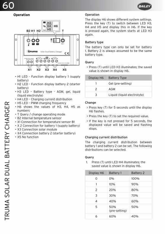
60TR
UM
A S
OLA
R D
UA
L B
ATT
ERY
CH
AR
GER
Operation
• H1 LED - Function display battery 1 (supply battery)
• H2 LED - Function display battery 2 (starter battery)
• H3 LED – Battery type - AGM, gel, liquid (liquid electrolyte)
• H4 LED – Charging current distribution• H5 LED – PWM charging frequency• H6 shows the values of H3, H4, H5 as
numbers• T Query / change operating mode• B2 Internal temperature sensor• X1 Connection for temperature sensor B1• X 2 Connection for battery 1 (supply battery)• X3 Connection solar module• X4 Connection battery 2 (starter battery)• X5 No function
Operation
The display H6 shows different system settings. Press the key (T) to switch between LED H3, H4 and H5 and display this in H6. If the key is pressed again, the system starts at LED H3 again.
Battery type
The battery type can only be set for battery 1. Battery 2 is always assumed to be the same battery type.
Query
> Press (T) until LED H3 illuminates; the saved value is shown in display H6.
Display H6 Battery Type
1 Gel (pre-setting)
2 AGM
3 Liquid (liquid electrolyte)
Change
> Press key (T) for 5 seconds until the display H6 flashes.
> Press the key (T) to set the required value.
> If the key is not pressed for 5 seconds, the displayed value will be saved and flashing stops.
Charging current distribution
The charging current distribution between battery 1 and battery 2 can be set. The following distributions can be selected.
Query
1. Press (T) until LED H4 illuminates; the saved value is shown in display H6.
Display H6 Battery 1 Battery 2
0 0% 100%
1 10% 90%
2 20% 80%
3 30% 70%
4 40% 60%
5 50%(pre-setting)
50%
6 60% 40%
61
TRU
MA
SO
LAR
DU
AL
BA
TTER
Y C
HA
RG
ER
7 70% 30%
8 80% 20%
9 90% 10%
Change
1. Press key (T) for 5 seconds until the display H6 flashes.
2. Press the key (T) to set the required value.
3. If the key is not pressed for 5 seconds, the displayed value will be saved and flashing stops.
NOTE: During the normal charging process, the device divides the charging current between battery 1 and battery 2 as set. Once the battery 1 is fully charged, all the charging current is fed to battery 2, regardless of the set value. If the voltage of battery 1 drops, the charging process starts again. If only battery 1 is connected, the entire charging current is supplied to this battery regardless of the set value.
PWM charging frequency
The pulse frequency of the device can be set here. This may be changed to reduce possible interferences.
Query
1. Press (T) until LED H5 illuminates; the saved value is shown in display H6.
Display H6 PWM charging frequency
0 25 Hz (pre-setting)
1 50 Hz
2 100 Hz
2. Press key (T) for 5 seconds until the display H6 flashes.
3. Press the key (T) to set the required value.
4. If the key is not pressed for 5 seconds, the displayed value will be saved and flashing stops.
Function display / troubleshooting
LED H1 (H2) shows the status of battery 1
(battery 2).
LED flashes in longer intervals:Check connections from the device to the battery and solar module, ensure that they are connected to the right terminals.
Test the fuse, solar module and the battery.
LED flashes:Battery is fully charged.
LED shines:The battery is being charged.
LED flashes in short intervals:The battery is not being charged. If necessary, replace faulty battery.
LED does not shine:Battery not connected or over-voltage.
If this does not solve the problem, please contact the Truma Service Center.
Safety instructions
WARNING: Failure to observe any of the below safety warnings may lead to serious injury or even death.
• The solar module generates power when light is cast on it. The full voltage is also available even if there is little light. The open circuit voltage may be twice as high. Do not touch any live parts.
• Do not step on or place any loads on the solar module.
• Do not drop.• Do not use a damaged solar module.• Only qualified technicians may assemble
and connect electrical devices• Never switch solar modules in sequence, as
this could lead to higher voltages.• Liquid electrolyte batteries can create
explosive gases, so ensure there is adequate ventilation. Check the liquid level at regular intervals.
• Overcharging can damage your battery; check the technical data for your battery to avoid this.
• Equalisation charging increases the charging voltage. This may damage the consumer unit. Ensure that all consumer units are designed for such voltages.
62TR
UM
A S
OLA
R D
UA
L B
ATT
ERY
CH
AR
GER
• Only operate devices with undamaged casings and cables. Ensure the cables are installed safely. Do not pull on the cables.
• Persons may be exposed to a risk of high voltage, if the front glass or lamination on the rear side is damaged.
• Batteries may generate explosive gases during charging and operation. Keep away from flames and ignition sources. Ensure there is sufficient ventilation in the battery chamber.
Maintenance
The power supply must always be disconnected before performing any maintenance work. Any light should be prevented from being cast upon the panels therefore you should completely cover the panel before attempting any maintanience. Clean the device with a dry and lint-free cloth.
Repairs
Do not repair or modify the device. Please contact your Bailey dealer.
The device is not suitable for charging:
• 6V batteries or 6V lead accumulators• non-chargeable batteries• nickel-cadmium batteries
If batteries with a rated voltage of 6V are charged with the device, gassing occurs immediately. An explosive gas can be created.
The device is only suitable for regulating solar modules. Do not connect any other voltage sources (e.g. main voltage 230V) to the device. This may destroy the device and/or sources. If any other voltage sources are used together with the device, please ask your dealer.
Battery care
The following points should be observed to extend the battery life:
• Batteries should be fully charged before and after being used.
• In the case of longer standstills (without
sunshine), disconnect the battery and charge for 24 hours at the latest every 12 weeks.
• Deep-discharged batteries can be permanently damaged. Equalisation charging cannot repair this.
NOTE: Store fully charged batteries in a cool but frost-free place during the winter and recharge regularly (every 12 weeks).
Disposal
The device must be disposed of in line with the administrative regulations of the respective country in which it is used.
National regulations and laws (in Germany, for example, the End-of-life Vehicle Regulation) must be observed.
Further information can be found on the Truma website: https://www.truma.com.
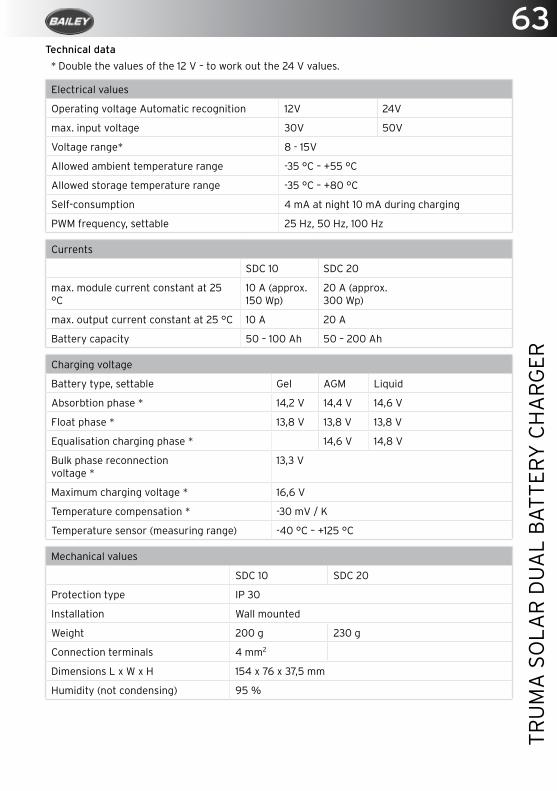
63
TRU
MA
SO
LAR
DU
AL
BA
TTER
Y C
HA
RG
ER
Technical data
* Double the values of the 12 V – to work out the 24 V values.
Electrical values
Operating voltage Automatic recognition 12V 24V
max. input voltage 30V 50V
Voltage range* 8 - 15V
Allowed ambient temperature range -35 °C – +55 °C
Allowed storage temperature range -35 °C – +80 °C
Self-consumption 4 mA at night 10 mA during charging
PWM frequency, settable 25 Hz, 50 Hz, 100 Hz
Currents
SDC 10 SDC 20
max. module current constant at 25 °C
10 A (approx. 150 Wp)
20 A (approx. 300 Wp)
max. output current constant at 25 °C 10 A 20 A
Battery capacity 50 – 100 Ah 50 – 200 Ah
Charging voltage
Battery type, settable Gel AGM Liquid
Absorbtion phase * 14,2 V 14,4 V 14,6 V
Float phase * 13,8 V 13,8 V 13,8 V
Equalisation charging phase * 14,6 V 14,8 V
Bulk phase reconnectionvoltage *
13,3 V
Maximum charging voltage * 16,6 V
Temperature compensation * -30 mV / K
Temperature sensor (measuring range) -40 °C – +125 °C
Mechanical values
SDC 10 SDC 20
Protection type IP 30
Installation Wall mounted
Weight 200 g 230 g
Connection terminals 4 mm2
Dimensions L x W x H 154 x 76 x 37,5 mm
Humidity (not condensing) 95 %

www.lumo.eu.com Customer Service: +44 (0) 1422 317 333 www.baileyofbristol.co.uk
Lumo are pleased to support Baileys new motorhome, The Autograph
Lumo Lighting, specialists in interior lights for all caravans and motorhomes. Full range available from Baileys and to view on our website at www.lumo.eu.com
65
THE
ALD
E H
EATI
NG
SY
STEM
The Alde Heating System
Specified Use ....................................................................................................................66
System Design ..................................................................................................................66
Gas Heating .......................................................................................................................66
Electric Heating ...............................................................................................................66
Domestic Hot Water ........................................................................................................ 67
Draining Fresh Water ......................................................................................................68
Heat Transfer Fluid ..........................................................................................................68
Filling .................................................................................................................................. 69
Central Heating ................................................................................................................ 69
Circulation Pump ............................................................................................................. 69
Bleeding Air From The System ..................................................................................... 69
Air Lock .............................................................................................................................. 70
LPG Safety ......................................................................................................................... 70
Flue ...................................................................................................................................... 71
Maintenance....................................................................................................................... 71
Winter ..................................................................................................................................72
The Alde Control Panel - Controlling The Heating System .....................................73
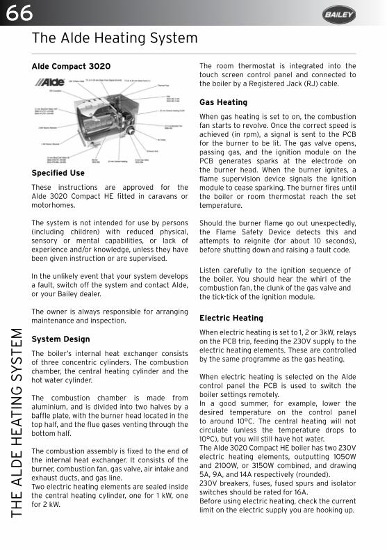
66TH
E A
LDE
HEA
TIN
G S
YST
EM
The Alde Heating System
Alde Compact 3020
Specified Use
These instructions are approved for the Alde 3020 Compact HE fitted in caravans or motorhomes.
The system is not intended for use by persons (including children) with reduced physical, sensory or mental capabilities, or lack of experience and/or knowledge, unless they have been given instruction or are supervised.
In the unlikely event that your system develops a fault, switch off the system and contact Alde, or your Bailey dealer.
The owner is always responsible for arranging maintenance and inspection.
System Design
The boiler’s internal heat exchanger consists of three concentric cylinders. The combustion chamber, the central heating cylinder and the hot water cylinder.
The combustion chamber is made from aluminium, and is divided into two halves by a baffle plate, with the burner head located in the top half, and the flue gases venting through the bottom half.
The combustion assembly is fixed to the end of the internal heat exchanger. It consists of the burner, combustion fan, gas valve, air intake and exhaust ducts, and gas line.Two electric heating elements are sealed inside the central heating cylinder, one for 1 kW, one for 2 kW.
The room thermostat is integrated into the touch screen control panel and connected to the boiler by a Registered Jack (RJ) cable.
Gas Heating
When gas heating is set to on, the combustion fan starts to revolve. Once the correct speed is achieved (in rpm), a signal is sent to the PCB for the burner to be lit. The gas valve opens, passing gas, and the ignition module on the PCB generates sparks at the electrode on the burner head. When the burner ignites, a flame supervision device signals the ignition module to cease sparking. The burner fires until the boiler or room thermostat reach the set temperature.
Should the burner flame go out unexpectedly, the Flame Safety Device detects this and attempts to reignite (for about 10 seconds), before shutting down and raising a fault code.
Listen carefully to the ignition sequence of the boiler. You should hear the whirl of the combustion fan, the clunk of the gas valve and the tick-tick of the ignition module.
Electric Heating
When electric heating is set to 1, 2 or 3kW, relays on the PCB trip, feeding the 230V supply to the electric heating elements. These are controlled by the same programme as the gas heating.
When electric heating is selected on the Alde control panel the PCB is used to switch the boiler settings remotely. In a good summer, for example, lower the desired temperature on the control panel to around 10°C. The central heating will not circulate (unless the temperature drops to 10°C), but you will still have hot water.The Alde 3020 Compact HE boiler has two 230V electric heating elements, outputting 1050W and 2100W, or 3150W combined, and drawing 5A, 9A, and 14A respectively (rounded).230V breakers, fuses, fused spurs and isolator switches should be rated for 16A.Before using electric heating, check the current limit on the electric supply you are hooking up.
67
THE
ALD
E H
EATI
NG
SY
STEM
• 6 A limit, only use 1 kW electric heating.• 10 A limit, use 1–2 kW electric heating.• 16 A limit, use 1–3 kW electric heating.
NOTE: If the electric supply has unstable voltage, the amperage will also fluctuate.
The optional Alde 3010-315 load monitor allows you to set a limit on the current drawn by the vehicle and the electric heating to automatically accommodate it.
Domestic Hot Water
Being a combi-type boiler, the Alde 3020 Compact HE has an integrated, stainless steel hot water cylinder that holds approximately 8.4 litres of fresh water.
The boiler can produce around 12 litres of 40°C warm water per 30 minutes (at a cold water temperature of 10°C). If only the electric heating is used, this capacity is slightly reduced.
Only use potable fresh water. Grey water, desalinated water, or water otherwise unfit to drink is not suitable for use as domestic hot water.
Where water quality is in doubt, precautions should be taken to ensure the stainless steel hot water cylinder is not damaged. Always flush out the hot water cylinder before use, especially when it has stood empty for some time. Any steriliser products should be suitable for use with stainless steel.
Avoid steriliser products containing sodium hydrochlorite, for example, as these will cause severe corrosion damage to the hot water cylinder, which is not covered under warranty. Read the product label or contact the product manufacturer for details.
When the hot water cylinder is in continuous use, it should be drained and refilled once a month. This recreates the air cushion in the hot water cylinder that absorbs pressure surges.
NOTE: If continuously using the hot water cylinder in a hard water area, fit an in-line scale inhibitor to minimise the effects of limescale.
Target hot water temperature is greater than 50 °C in normal operation, to prevent the growth of Legionella. Over 50 °C , the hot water will be heated to the maximum achievable temperature at the time. This allows the hot water to achieve disinfection temperatures, and increases warm water performance.
If scalding hot water temperatures are a concern – such as with the young, elderly or infirm – thermostatic mixing valves (TMVs) can be fitted, and may be required by local regulations.
IMPORTANT: Always drain down and completely empty the hot water cylinder when there is risk of frost, unless the vehicle is explicitly stated to be self-winterising by the vehicle manufacturer.
WARNING: Failure to drain the hot water cylinder when there is a risk of frost may result in frost damage, which is not covered under warranty.

68TH
E A
LDE
HEA
TIN
G S
YST
EM
Draining Fresh Water
Opening manual safety valve/drain valve
1. Switch off the water pump.
2. Open all water taps, showers, etc.
3. Open the safety/drain valve by lifting the tab (This is yellow in colour).
4. The system will drain directly below the vehicle through the clear plastic hose on the safety/drain valve. Check that all water has emptied out (7–10 litres). Leave the valve in the open position until the next time the hot water cylinder is used.
5. Check that the breather valve is allowing air to enter the hot water cylinder, when it is being drained, and that the clear plastic hose is not obstructed.
Heat Transfer Fluid
The central heating system must be is filled with Heat Transfer Fluid (HTF); a solution of 50% ethylene glycol antifreeze and 50% water.
The antifreeze manufacturer will have a maximum water hardness recommendation, though deionised water (0 ppm) is always preferred. Read the product label or contact the product manufacturer for details.
Alde recommends Alde Premium G13 Ready to Use Antifreeze.
50:50 ethylene glycol antifreeze and water will protect against frost down to -35–-37 °C. A refractometer and/or hydrometer can be used to measure the strength of the antifreeze solution.
Corrosion protection will vary depending on the lifespan of the antifreeze. Read the product label or contact the product manufacturer for details.
WARNING: Always replace the HTF in accordance with the antifreeze product’s lifespan. If in any doubt, replace the HTF after 2 years.
WARNING: The boiler must NOT be switched on if there is no HTF in the system.
The corrosion inhibitors found in ethylene glycol antifreeze may not be cross-compatible. When topping up or replacing the HTF, ensure the new antifreeze is compatible with the current antifreeze product. Read the product label or contact the product manufacturer for details.
NOTE: As a guideline, blue and red antifreeze products are NOT compatible with each other, but VAG G12++ and G13 spec antifreeze (magenta) is compatible with both.
Failure to fill with suitable HTF may result in severe damage to your Alde system, and is not covered under warranty. We recommend you contact the Bailey retailer for the replacement of HTF.
Breather Valve
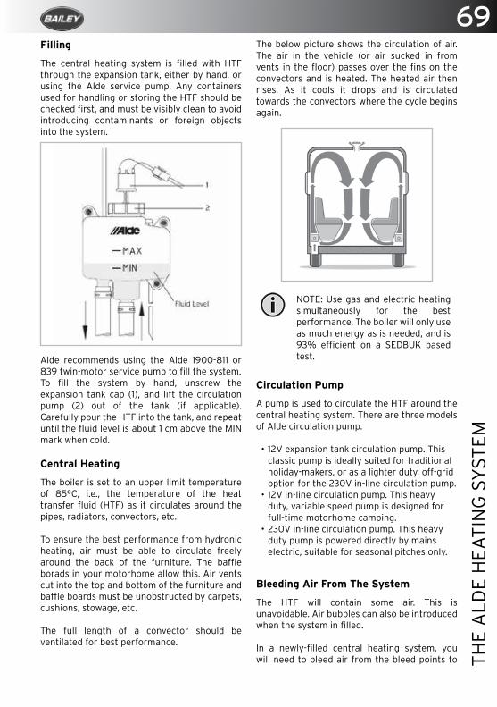
69
THE
ALD
E H
EATI
NG
SY
STEM
Filling
The central heating system is filled with HTF through the expansion tank, either by hand, or using the Alde service pump. Any containers used for handling or storing the HTF should be checked first, and must be visibly clean to avoid introducing contaminants or foreign objects into the system.
Alde recommends using the Alde 1900-811 or 839 twin-motor service pump to fill the system.To fill the system by hand, unscrew the expansion tank cap (1), and lift the circulation pump (2) out of the tank (if applicable). Carefully pour the HTF into the tank, and repeat until the fluid level is about 1 cm above the MIN mark when cold.
Central Heating
The boiler is set to an upper limit temperature of 85°C, i.e., the temperature of the heat transfer fluid (HTF) as it circulates around the pipes, radiators, convectors, etc.
To ensure the best performance from hydronic heating, air must be able to circulate freely around the back of the furniture. The baffle borads in your motorhome allow this. Air vents cut into the top and bottom of the furniture and baffle boards must be unobstructed by carpets, cushions, stowage, etc.
The full length of a convector should be ventilated for best performance.
The below picture shows the circulation of air. The air in the vehicle (or air sucked in from vents in the floor) passes over the fins on the convectors and is heated. The heated air then rises. As it cools it drops and is circulated towards the convectors where the cycle begins again.
NOTE: Use gas and electric heating simultaneously for the best performance. The boiler will only use as much energy as is needed, and is 93% efficient on a SEDBUK based test.
Circulation Pump
A pump is used to circulate the HTF around the central heating system. There are three models of Alde circulation pump.
• 12V expansion tank circulation pump. This classic pump is ideally suited for traditional holiday-makers, or as a lighter duty, off-grid option for the 230V in-line circulation pump.
• 12V in-line circulation pump. This heavy duty, variable speed pump is designed for full-time motorhome camping.
• 230V in-line circulation pump. This heavy duty pump is powered directly by mains electric, suitable for seasonal pitches only.
Bleeding Air From The System
The HTF will contain some air. This is unavoidable. Air bubbles can also be introduced when the system in filled.
In a newly-filled central heating system, you will need to bleed air from the bleed points to
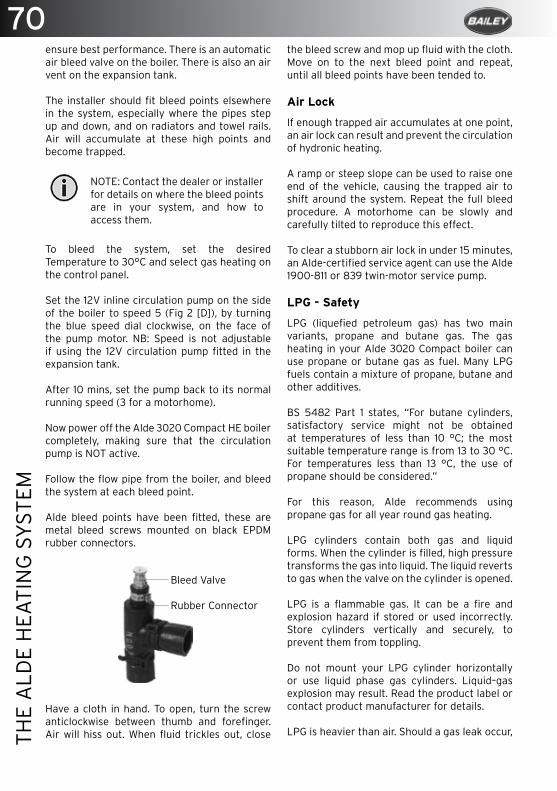
70TH
E A
LDE
HEA
TIN
G S
YST
EM
ensure best performance. There is an automatic air bleed valve on the boiler. There is also an air vent on the expansion tank.
The installer should fit bleed points elsewhere in the system, especially where the pipes step up and down, and on radiators and towel rails. Air will accumulate at these high points and become trapped.
NOTE: Contact the dealer or installer for details on where the bleed points are in your system, and how to access them.
To bleed the system, set the desired Temperature to 30°C and select gas heating on the control panel.
Set the 12V inline circulation pump on the side of the boiler to speed 5 (Fig 2 [D]), by turning the blue speed dial clockwise, on the face of the pump motor. NB: Speed is not adjustable if using the 12V circulation pump fitted in the expansion tank.
After 10 mins, set the pump back to its normal running speed (3 for a motorhome).
Now power off the Alde 3020 Compact HE boiler completely, making sure that the circulation pump is NOT active.
Follow the flow pipe from the boiler, and bleed the system at each bleed point.
Alde bleed points have been fitted, these are metal bleed screws mounted on black EPDM rubber connectors.
Have a cloth in hand. To open, turn the screw anticlockwise between thumb and forefinger. Air will hiss out. When fluid trickles out, close
the bleed screw and mop up fluid with the cloth.Move on to the next bleed point and repeat, until all bleed points have been tended to.
Air Lock
If enough trapped air accumulates at one point, an air lock can result and prevent the circulation of hydronic heating.
A ramp or steep slope can be used to raise one end of the vehicle, causing the trapped air to shift around the system. Repeat the full bleed procedure. A motorhome can be slowly and carefully tilted to reproduce this effect.
To clear a stubborn air lock in under 15 minutes, an Alde-certified service agent can use the Alde 1900-811 or 839 twin-motor service pump.
LPG - Safety
LPG (liquefied petroleum gas) has two main variants, propane and butane gas. The gas heating in your Alde 3020 Compact boiler can use propane or butane gas as fuel. Many LPG fuels contain a mixture of propane, butane and other additives.
BS 5482 Part 1 states, “For butane cylinders, satisfactory service might not be obtained at temperatures of less than 10 °C; the most suitable temperature range is from 13 to 30 °C. For temperatures less than 13 °C, the use of propane should be considered.”
For this reason, Alde recommends using propane gas for all year round gas heating.
LPG cylinders contain both gas and liquid forms. When the cylinder is filled, high pressure transforms the gas into liquid. The liquid reverts to gas when the valve on the cylinder is opened.
LPG is a flammable gas. It can be a fire and explosion hazard if stored or used incorrectly. Store cylinders vertically and securely, to prevent them from toppling.
Do not mount your LPG cylinder horizontally or use liquid phase gas cylinders. Liquid–gas explosion may result. Read the product label or contact product manufacturer for details.
LPG is heavier than air. Should a gas leak occur,
Bleed Valve
Rubber Connector
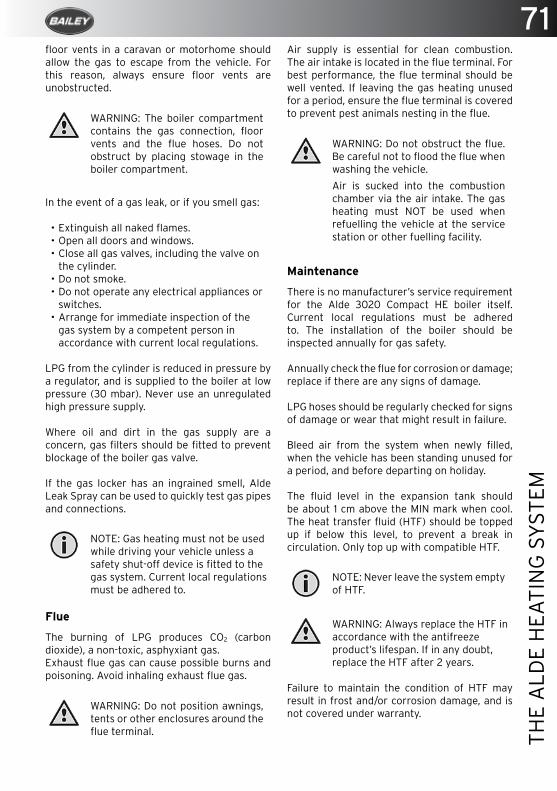
71
THE
ALD
E H
EATI
NG
SY
STEM
floor vents in a caravan or motorhome should allow the gas to escape from the vehicle. For this reason, always ensure floor vents are unobstructed.
WARNING: The boiler compartment contains the gas connection, floor vents and the flue hoses. Do not obstruct by placing stowage in the boiler compartment.
In the event of a gas leak, or if you smell gas:
• Extinguish all naked flames.• Open all doors and windows.• Close all gas valves, including the valve on
the cylinder.• Do not smoke.• Do not operate any electrical appliances or
switches.• Arrange for immediate inspection of the
gas system by a competent person in accordance with current local regulations.
LPG from the cylinder is reduced in pressure by a regulator, and is supplied to the boiler at low pressure (30 mbar). Never use an unregulated high pressure supply.
Where oil and dirt in the gas supply are a concern, gas filters should be fitted to prevent blockage of the boiler gas valve.
If the gas locker has an ingrained smell, Alde Leak Spray can be used to quickly test gas pipes and connections.
NOTE: Gas heating must not be used while driving your vehicle unless a safety shut-off device is fitted to the gas system. Current local regulations must be adhered to.
Flue
The burning of LPG produces CO2 (carbon dioxide), a non-toxic, asphyxiant gas.Exhaust flue gas can cause possible burns and poisoning. Avoid inhaling exhaust flue gas.
WARNING: Do not position awnings, tents or other enclosures around the flue terminal.
Air supply is essential for clean combustion. The air intake is located in the flue terminal. For best performance, the flue terminal should be well vented. If leaving the gas heating unused for a period, ensure the flue terminal is covered to prevent pest animals nesting in the flue.
WARNING: Do not obstruct the flue. Be careful not to flood the flue when washing the vehicle.
Air is sucked into the combustion chamber via the air intake. The gas heating must NOT be used when refuelling the vehicle at the service station or other fuelling facility.
Maintenance
There is no manufacturer’s service requirement for the Alde 3020 Compact HE boiler itself. Current local regulations must be adhered to. The installation of the boiler should be inspected annually for gas safety.
Annually check the flue for corrosion or damage; replace if there are any signs of damage.
LPG hoses should be regularly checked for signs of damage or wear that might result in failure.
Bleed air from the system when newly filled, when the vehicle has been standing unused for a period, and before departing on holiday.
The fluid level in the expansion tank should be about 1 cm above the MIN mark when cool. The heat transfer fluid (HTF) should be topped up if below this level, to prevent a break in circulation. Only top up with compatible HTF.
NOTE: Never leave the system empty of HTF.
WARNING: Always replace the HTF in accordance with the antifreeze product’s lifespan. If in any doubt, replace the HTF after 2 years.
Failure to maintain the condition of HTF may result in frost and/or corrosion damage, and is not covered under warranty.
72TH
E A
LDE
HEA
TIN
G S
YST
EM
When the hot water cylinder is in continuous use, it should be drained and refilled once a month. This recreates the air cushion in the hot water cylinder that absorbs pressure surges.
The Alde control panel requires no maintenance, other than cleaning of the screen as needed. Use a microfibre cloth to clean the touchscreen.
Panel radiators and towel rails should be regularly cleaned with a cloth and multi-purpose cleaner.
When shut down, the system has a normal draw on the 12V leisure battery of approximately 60 mA.
Winter
When camping in the winter, always ensure the flue terminal remains unobstructed by snow and ice. Extensions for roof flue terminals, and condensate spouts for side flue terminals are available from Alde.
Check the strength of the heat transfer fluid (HTF) with a hydrometer and/or refractometer. It should measure 50% ethylene glycol antifreeze, or -35–-37 °C.
The central heating can still be used with no fresh water in the system. The air in the hot water cylinder is heated but no damage can result.
WARNING: Always drain down and completely empty the hot water cylinder when there is risk of frost, unless the vehicle is explicitly stated to be self-winterising by the vehicle manufacturer.
If camping in temperatures below -10 °C, consider carrying spare parts in the event of an emergency. Alde recommends a 12V circulation pump for the expansion tank (with cabling), a PCB, and 4–5 litres of ready to use antifreeze. These spare parts should be kept well insulated and in the warmest part of the vehicle; for example, in the wardrobe, near to the expansion tank pipes.
If storing the vehicle for winter, ensure the flue terminal is covered to prevent pest animals nesting in the flue. NB: Consider removing the Alde control panel over winter, if the vehicle is to be kept in storage and is susceptible to damp.
If using the lighter duty 12V circulation pump in the expansion tank, do not leave the central heating on over winter, even with a low desired temperature set.
NOTE: Air the vehicle over winter without wearing out the lighter duty pump. Use Delayed Start/Cycle on the Alde control panel to automatically heat the vehicle for 24 hours, once a week.

73
THE
ALD
E H
EATI
NG
SY
STEM
Standby Screen
The Standby Screen is displayed after the Splash Screen. This screen contains useful information about the status of your heating system.
A. Clock is enabled. Day of the week and time shown.
B. Outdoor temperature. [Optional outdoor temperature sensor required.]
C. Room temperature. Measured at the control panel. [Optional discrete room temperature sensors available.]
D. Central heating circulation pump is active.
E. Delayed Start/Cycle is enabled.
F. Day Mode active.
G. Gas cylinder status. Full/empty and EisEx mode shown. [Additional accessories required.]
H. Night Mode active.
I. 230V supply. If not displayed, the boiler is not receiving 230V supply.
J. Power button. Press to switch system on-off. Lit green LED indicates system is on.
K. MENU button. Press to access Main Menu from Standby Screen or Settings Menu.
NOTE: If the Standby Screen is set to “Dark” in Backlight settings, the Standby Screen will not be displayed; the screen will be dark.
The Alde Control Panel - Controlling The Heating System
The Alde 3020 Compact HE control panel has two hard buttons and a non-capacitive, colour touchscreen interface. The buttons displayed on the screen are operated by touching the screen with your finger.
Starting the System
1. Both the control panel and boiler are off.
2. To start the system, press the Power button on the control panel. The Splash Screen is displayed and green LED is lit. The boiler will now start with the previously saved settings (factory settings by default).
The system will now be drawing variable 0.1–1.5 A of current from the 12V supply.

74TH
E A
LDE
HEA
TIN
G S
YST
EM
> The current desired room temperature is displayed.
> Adjust by pressing either the Plus or Minus button.
Domestic Hot Water The Alde boiler stores 8.4 Litres of hot water as standard. If the hot water cylinder is empty, the air is heated but no damage will result.
NOTE: If the Day or Night Mode Hot Water Ignore is active, the hot water cannot be adjusted. The Plus and Minus buttons will be greyed out.
> Hot Water Ignore. Volume bar shown empty. No attempt will be made to heat hot water specifically. This saves energy when the fresh water is drained down.
> Hot Water Normal. Volume bar shown half-full. Hot water is heated to greater than 50 °C. NB: If Circulation Pump is set to Continuous, this option will not be available.
> Hot Water Boost. Volume bar full. Central heating circulation is disabled for 30 mins. Hot water is heated to greater than 65 °C. After 30 mins the system reverts to Hot Water Normal.
> Adjust the volume bar by pressing Plus or Minus button.
Electric Heating
Check that 230V supply is displayed on the Standby Screen. The Alde boiler is programmed to use power economically and there are times when it may use no power at all, even if set to 3 kW.
1. Select 1, 2 or 3 kW electric heating. More power equals better performance, but may be restricted by the current (amps) limit on the electric hook-up.
2. Adjust by pressing Plus or Minus button.
Max current draw from 230V supply is 4.5 Amps on 1 kW, 9 Amps on 2 kW, 14 Amps on 3 kW. If the electricity supply has unstable voltage, the amperage will also fluctuate.
Main Menu
Press MENU button to access the Main Menu from the Standby Screen or Settings Menu. The screen will revert to the Standby Screen after 30 secs if untouched.
1. Standby Screen. Press MENU button.
2. Main Menu.
a. What’s Activated Menu. (Not displayed if no activated functions are detected.)
b. Settings Menu
Desired Room Temperature
The desired room temperature can be set from 5 to 30°C, in 0.5 increments.
The World Health Organisation recommends a room temperature of 18–24°C for healthy living.
NOTE: If Day or Night Mode are active, the temperature cannot be adjusted, and the Plus and Minus buttons will be greyed out.
75
THE
ALD
E H
EATI
NG
SY
STEM
Restore default factory settings
Before using the system for the first time, restore default factory settings. Your control panel may have been tested by the dealer or installer, and some settings may have been changed unintentionally.
1. Press Tool button to access the Settings Menu (bottom right in Main Menu).
2. Press down arrow, until Reset button is displayed.
3. Press the Reset button to proceed.
>
Setup 12V circulation pump in expansion tank
To use the 12V circulation pump in the expansion tank, you must set it up. This is not a default factory setting. NB: This only applies if you have the 12V circulation pump in the expansion tank.
1. Press Tool button to access the Settings Menu (bottom right in Main Menu).
2. Press down arrow, until Installed Accessories button is displayed.
3. Press the Installed Accessories button to access the menu. Find and tick “Optional Pump” by pressing the box. Next, find and untick “Main Manual 12V”.
> > Setup Standby Screen for Bedtime
The backlight on the Standby Screen can be disturbing if the control panel is visible from your bed. It can be inverted for white text on black background.
1. Press Tool button to access the Settings Menu (bottom right in Main Menu).
2. Press down arrow, until Backlight button is displayed.
3. Press Backlight button, select Invert to proceed.
>
Gas Heating
The gas burner has two stages and will shift dynamically between low or full flame. There are times when it may use no power at all, even if gas heating is selected.
1. Press the Flame button to select gas heating. Green is on, blue is off.
Use both gas and electric heating simultaneously for best performance.
Climate Control
The AC button is displayed when a Truma Aventa Comfort air-conditioning unit is connected to the Alde control panel. This allows fully automatic climate control, with the heating and air-conditioning working in unison.
3. Set the desired room temperature as normal.
4. Press the AC button. Green is on, blue is off. The heating and air-conditioning will actively maintain the room temperature.
Alde recommends using the 3020-346 discrete room temperature sensor for accurate climate control. It should be located where the heating and air-con have a balanced effect on temperature.
Shutting Down the System
To save energy, the control panel only updates the boiler after the last adjustment is made. Wait 10 secs before shutting down the system to ensure the boiler is updated.
1. Press the Power button. The screen goes dark, the green LED is unlit. The system is off.
Setup
How you set up your system will depend on what accessories are installed and your user preferences. To get you started, here’s how to setup some of the more common features.

76TH
E A
LDE
HEA
TIN
G S
YST
EM
> Check the 12V cable is plugged into the boiler. Check the cable is plugged into the Alde control panel.
The boiler will not ignite on gas, but no error message
> The system may not need to use gas heating if also using electric heating.
> The fluids in the boiler may already be at operating temperature.
The boiler will not heat on 230V electric
> Check the circuit breaker and any 230V fuses.
> Check that any 230V fused spurs are on (they will often have an LED indicator and 230V fuse).
> Check the 230V supply (also indicated on the Standby Screen).
> The fluids in the boiler may already be at operating temperature.
No hot water
> Check that Hot Water Ignore is not activated on the Alde control panel.
> Check that Continuous pumping is not activated on the Alde control panel.
> Check for other conflicting settings on the Alde control panel or restore factory defaults.
> Check the water pump and cold water supply to the boiler.
No central heating
> Bleed the system of air.
> Check the fluid level in the expansion tank.
> Check that the circulation pump is responding.
> Check that hot water boost is not activated on the Alde control panel.
> If electric heating is not being used, set it to “Off” on the Alde control panel.
> Use gas and electric heating for best performance.
> Check that top and bottom vents in the furniture are not obstructed.
> Check the condition of the heat transfer fluid.
> Most vehicles will reach a comfortable temperature within 40 mins, in non-extreme conditions.
Set up Antimicrobial Function
To actively kill Legionella, setup the Antimicrobial function. At 2:00 every night, the hot water will be heated to over 65 °C for 30 mins. This further reduces the risk of Legionella.
1. Press Tool button to access the Settings Menu (bottom right in Main Menu).
2. Press Clock button, set the time and day. Press Return.
3. Press down arrow, until Antimicrobial button is displayed.
4. Press Antimicrobial button to proceed.
>
Settings
To learn more about the Settings Menu and programmable features of your Alde heating system, the complete operating instructions can be downloaded from www.alde.co.uk
To store programmable features between sites the optional Alde 3020-420 AA battery backup is required.
Maintenance
The Alde control panel requires no maintenance, other than cleaning of the screen as needed. Use a microfibre cloth to clean the touchscreen.NB: Consider removing the Alde control panel over winter, if the vehicle is to be kept in storage and is susceptible to damp.
Troubleshooting
Any error messages will be displayed on the Standby Screen. Error messages can be cleared by removing 12V supply to the boiler for 10 secs.
The system is completely dead, the control panel is blank
> Check the 20 mm T3.15 Amp glass fuse in the boiler. This is located under the lid of the black plastic service hatch, in a green plastic fuse holder.
> Check the 12V supply to the boiler, it should be above 12V.

77
THE
ALD
E H
EATI
NG
SY
STEM
control panel, but not excessive weight from free-hanging/unmanaged cable.
“Window open”
> Optional window sensor has triggered; gas heating is suspended. Automatically clears and gas heating resumes when window is closed.
“3rd Party Panel C. Fail”
> Break in communications between Alde control panel and third party control panel.
> Check the cable between the Alde control panel and third party control panel.
> Third party control panel is installed in software but not fitted.
> Untick “Third Party Panel” in Installed Accessories Menu.
“Low battery”
> 12V supply to boiler has dropped below 10.5V, possibly causing system brownout.
> Automatically clears when 12V supply reaches 11V.
“No match Heater/Panel”
> EM interference from 230V power, if cables are bundled together.
> Conductive dirt in socket. Plug Alde control panel cable into the alternative TIN bus sockets.
If problems persist, please contact Alde, or your dealer or installer.For our frequently asked questions, or download all instruction manuals, please visit our web site at www.alde.co.uk
Circulation pump is noisy
> Bleed the system of air.
> Check fluid level in the expansion tank.
> If the inline pump, check speed dial on pump is set to 2–3.
“Panel failure 1” & “Panel failure 2”
> Moisture is trapped in the control panel.
> Remove the Alde control panel from the vehicle and air in a warm, dry place overnight.
“Gas failure”
> Out of gas or gas is not igniting.
> Check the gas cylinder is full. Try a different gas cylinder, ensuring it is propane gas.
> Check the gas regulator and any isolation valves are open and not frozen.
“Overheat red fail” or “Overheat blue fail”
> Bleed the system of air.
> Check the fluid level in the expansion tank. It should be 1 cm above Min mark when cool.
> Check the correct circulation pump is installed, selected and responding.
> 12V supply to the boiler dropped to 7V momentarily. Check 12V supply for stability.
> Wait 30 minutes for the fluid to cool down.
“Overheat PCB”
> Failsafe in boiler has triggered.
> Check the fluid level in the expansion tank. It should be 1 cm above the Min mark when cool.
> Check the boiler compartment is ventilated, and that the vents are unobstructed. Do not place stowage in the boiler compartment.
“Fan failure”
> Combustion fan speed too low after multiple attempts. Bearing may be stiff after a period of disuse.
> Check for instability in 12V supply.
“Connection failure”
> Loose connection between Alde control panel and boiler.
> Unplug cable at the control panel and boiler, then carefully plug back in.
> Check there is slack on the cable at the
78TH
E A
LDE
HEA
TIN
G S
YST
EM
Alde Warranty
Alde undertakes to rectify any manufacturing defect or early component failure through normal use that occurs within 2 years of the installation date.
If your Alde boiler develops a fault, your first action should be to contact your dealer or installer, as they will be familiar with your installation and vehicle, and how to make a claim under warranty.
Alde International (UK) Ltd Huxley Close Park Farm South Wellingborough NorthantsNN8 6ABTel. 01933 677765 www.alde.co.uk
79
THE
SEA
TTLE
CO
NTR
OL
PAN
EL
The Seattle Control Panel
Home Screen ....................................................................................................................80
Navigation .........................................................................................................................80
Control Panel Buttons .....................................................................................................81
Mode Description ............................................................................................................. 82
Settings .............................................................................................................................. 83
Whale Space Heater (Advance models only) ............................................................84
Whale Space Heater Mode Selection Table ...............................................................84
Whale Water Heater (Advance models only) .............................................................85
Whale Water Heater Mode Selection Table ...............................................................85

80TH
E SE
ATT
LE C
ON
TRO
L PA
NEL
The Seattle Control Panel
Home Screen
The home screen is displayed by default. The control panel displays the time as well as any relevant notifications or warnings that are present. If left idle the control panel will return to this screen.
Setting the time:
1. From the home screen, press and hold down the ENTER button for 3 seconds until the hours begin to flash.
2. Press the UP or DOWN arrows to change the hour.
3. Press the ENTER button to set the hour; minutes will then flash.
4. Press the UP or DOWN arrows to change minutes.
5. Press ENTER to finish.
The control panel provides the user with a central point to check the following devices:
• Fresh water tank level.• Waste water tank level.• Inside temperature.• Outside temperature.• User Settings.• Battery selection; leisure or vehicle.• Leisure battery voltage. • Leisure battery amps.
Optional audio and visual warnings are displayed when necessary for:
• Low battery (leisure).• Low battery (vehicle).• Low level (fresh water tank).• High level (waste water tank).• High power drain (leisure battery).• Loss of 230V mains supply.• Function buttons.
Navigation
1. You can scroll through the settings with the up or down arrow.
2. To edit a setting, scroll to it then press ENTER to select.
3. If there are several options, you may need to use the arrow buttons to change value.
4. Press ENTER to accept new value.
5. To exit, scroll to “Exit to main menu” and press ENTER.
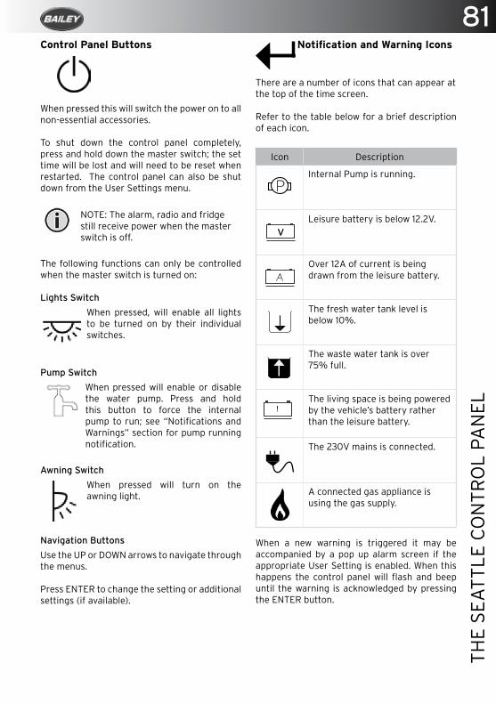
81
THE
SEA
TTLE
CO
NTR
OL
PAN
EL
Control Panel Buttons
When pressed this will switch the power on to all non-essential accessories.
To shut down the control panel completely, press and hold down the master switch; the set time will be lost and will need to be reset when restarted. The control panel can also be shut down from the User Settings menu.
NOTE: The alarm, radio and fridge still receive power when the master switch is off.
The following functions can only be controlled when the master switch is turned on:
Lights Switch
When pressed, will enable all lights to be turned on by their individual switches.
Pump Switch
When pressed will enable or disable the water pump. Press and hold this button to force the internal pump to run; see “Notifications and Warnings” section for pump running notification.
Awning Switch
When pressed will turn on the awning light.
Navigation Buttons
Use the UP or DOWN arrows to navigate through the menus.
Press ENTER to change the setting or additional settings (if available).
Notification and Warning Icons
There are a number of icons that can appear atthe top of the time screen.
Refer to the table below for a brief description of each icon.
Icon Description
PInternal Pump is running.
vLeisure battery is below 12.2V.
Over 12A of current is being drawn from the leisure battery.
The fresh water tank level is below 10%.
The waste water tank is over 75% full.
!The living space is being powered by the vehicle’s battery rather than the leisure battery.
The 230V mains is connected.
A connected gas appliance is using the gas supply.
When a new warning is triggered it may be accompanied by a pop up alarm screen if the appropriate User Setting is enabled. When this happens the control panel will flash and beep until the warning is acknowledged by pressing the ENTER button.
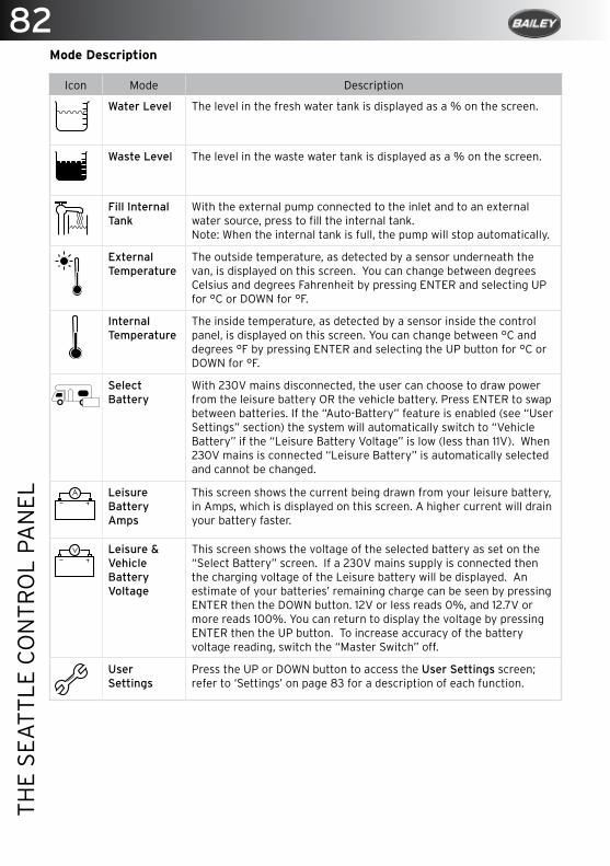
82TH
E SE
ATT
LE C
ON
TRO
L PA
NEL
Mode Description
Icon Mode Description
Water Level The level in the fresh water tank is displayed as a % on the screen.
Waste Level The level in the waste water tank is displayed as a % on the screen.
Fill Internal Tank
With the external pump connected to the inlet and to an external water source, press to fill the internal tank.Note: When the internal tank is full, the pump will stop automatically.
External Temperature
The outside temperature, as detected by a sensor underneath the van, is displayed on this screen. You can change between degrees Celsius and degrees Fahrenheit by pressing ENTER and selecting UP for °C or DOWN for °F.
Internal Temperature
The inside temperature, as detected by a sensor inside the control panel, is displayed on this screen. You can change between °C and degrees °F by pressing ENTER and selecting the UP button for °C or DOWN for °F.
Select Battery
With 230V mains disconnected, the user can choose to draw power from the leisure battery OR the vehicle battery. Press ENTER to swap between batteries. If the “Auto-Battery” feature is enabled (see “User Settings” section) the system will automatically switch to “Vehicle Battery” if the “Leisure Battery Voltage” is low (less than 11V). When 230V mains is connected “Leisure Battery” is automatically selected and cannot be changed.
Leisure Battery Amps
This screen shows the current being drawn from your leisure battery, in Amps, which is displayed on this screen. A higher current will drain your battery faster.
Leisure & Vehicle Battery Voltage
This screen shows the voltage of the selected battery as set on the “Select Battery” screen. If a 230V mains supply is connected then the charging voltage of the Leisure battery will be displayed. An estimate of your batteries’ remaining charge can be seen by pressing ENTER then the DOWN button. 12V or less reads 0%, and 12.7V or more reads 100%. You can return to display the voltage by pressing ENTER then the UP button. To increase accuracy of the battery voltage reading, switch the “Master Switch” off.
User Settings
Press the UP or DOWN button to access the User Settings screen;refer to ‘Settings’ on page 83 for a description of each function.
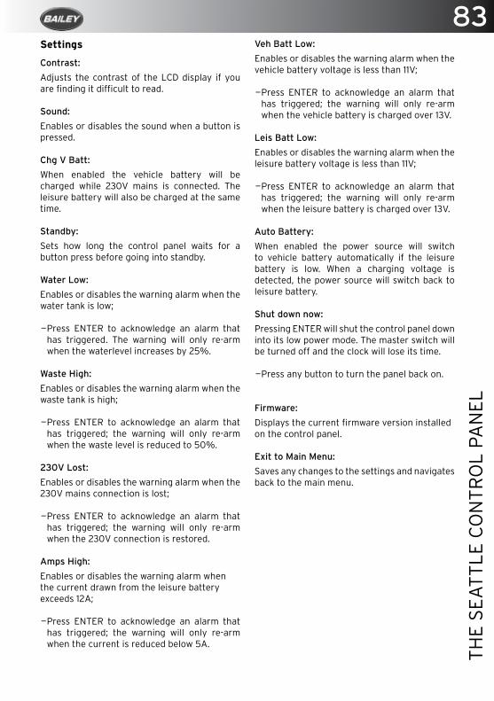
83
THE
SEA
TTLE
CO
NTR
OL
PAN
EL
Settings
Contrast:
Adjusts the contrast of the LCD display if you are finding it difficult to read.
Sound:
Enables or disables the sound when a button is pressed.
Chg V Batt:
When enabled the vehicle battery will be charged while 230V mains is connected. The leisure battery will also be charged at the same time.
Standby:
Sets how long the control panel waits for a button press before going into standby.
Water Low:
Enables or disables the warning alarm when the water tank is low;
—Press ENTER to acknowledge an alarm that has triggered. The warning will only re-arm when the waterlevel increases by 25%.
Waste High:
Enables or disables the warning alarm when the waste tank is high;
—Press ENTER to acknowledge an alarm that has triggered; the warning will only re-arm when the waste level is reduced to 50%.
230V Lost:
Enables or disables the warning alarm when the 230V mains connection is lost;
—Press ENTER to acknowledge an alarm that has triggered; the warning will only re-arm when the 230V connection is restored.
Amps High:
Enables or disables the warning alarm whenthe current drawn from the leisure batteryexceeds 12A;
—Press ENTER to acknowledge an alarm that has triggered; the warning will only re-arm when the current is reduced below 5A.
Veh Batt Low:
Enables or disables the warning alarm when the vehicle battery voltage is less than 11V;
—Press ENTER to acknowledge an alarm that has triggered; the warning will only re-arm when the vehicle battery is charged over 13V.
Leis Batt Low:
Enables or disables the warning alarm when the leisure battery voltage is less than 11V;
—Press ENTER to acknowledge an alarm that has triggered; the warning will only re-arm when the leisure battery is charged over 13V.
Auto Battery:
When enabled the power source will switch to vehicle battery automatically if the leisure battery is low. When a charging voltage is detected, the power source will switch back to leisure battery.
Shut down now:
Pressing ENTER will shut the control panel down into its low power mode. The master switch will be turned off and the clock will lose its time.
—Press any button to turn the panel back on.
Firmware:
Displays the current firmware version installedon the control panel.
Exit to Main Menu:
Saves any changes to the settings and navigates back to the main menu.
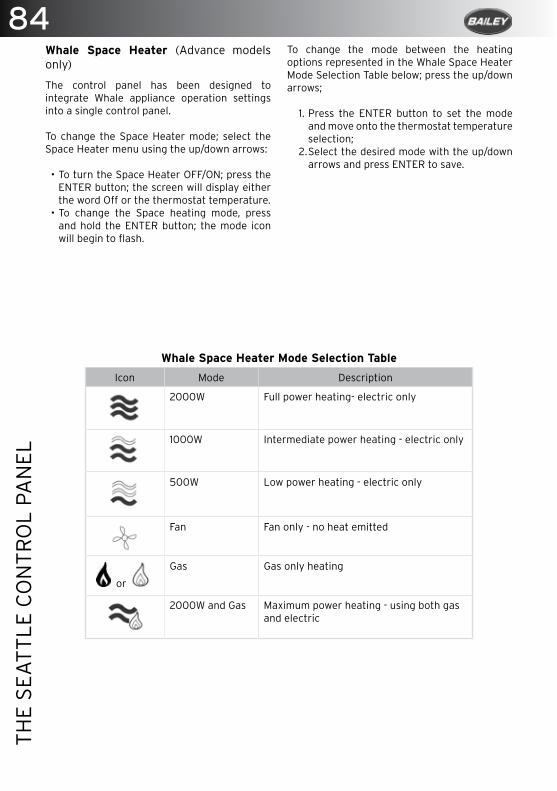
84TH
E SE
ATT
LE C
ON
TRO
L PA
NEL
Whale Space Heater (Advance models only)
The control panel has been designed to integrate Whale appliance operation settings into a single control panel.
To change the Space Heater mode; select the Space Heater menu using the up/down arrows:
• To turn the Space Heater OFF/ON; press the ENTER button; the screen will display either the word Off or the thermostat temperature.
• To change the Space heating mode, press and hold the ENTER button; the mode icon will begin to flash.
Whale Space Heater Mode Selection Table
Icon Mode Description
2000W Full power heating- electric only
1000W Intermediate power heating - electric only
500W Low power heating - electric only
Fan Fan only - no heat emitted
or
Gas Gas only heating
2000W and Gas Maximum power heating - using both gas and electric
To change the mode between the heating options represented in the Whale Space Heater Mode Selection Table below; press the up/down arrows;
1. Press the ENTER button to set the mode and move onto the thermostat temperature selection;
2. Select the desired mode with the up/down arrows and press ENTER to save.
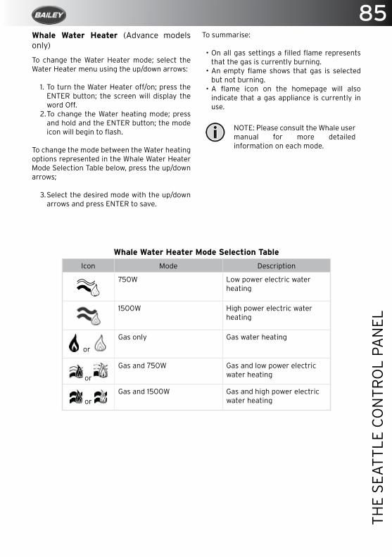
85
THE
SEA
TTLE
CO
NTR
OL
PAN
EL
Whale Water Heater Mode Selection Table
Icon Mode Description
750W Low power electric water heating
1500W High power electric water heating
or
Gas only Gas water heating
or
Gas and 750W Gas and low power electric water heating
or Gas and 1500W Gas and high power electric
water heating
Whale Water Heater (Advance models only)
To change the Water Heater mode; select the Water Heater menu using the up/down arrows:
1. To turn the Water Heater off/on; press the ENTER button; the screen will display the word Off.
2. To change the Water heating mode; press and hold and the ENTER button; the mode icon will begin to flash.
To change the mode between the Water heating options represented in the Whale Water Heater Mode Selection Table below, press the up/down arrows;
3. Select the desired mode with the up/down arrows and press ENTER to save.
To summarise:
• On all gas settings a filled flame represents that the gas is currently burning.
• An empty flame shows that gas is selected but not burning.
• A flame icon on the homepage will also indicate that a gas appliance is currently in use.
NOTE: Please consult the Whale user manual for more detailed information on each mode.
The Whale Space and Water Heater
Whale Space Heater ........................................................................................................86
Instructions For Safe Use .............................................................................................. 87
Maintenance...................................................................................................................... 87
Whale Water Heater ........................................................................................................88
Instructions For Safe Use ..............................................................................................88
Maintenance......................................................................................................................88
Troubleshooting ...............................................................................................................89
Troubleshooting table .....................................................................................................90
86TH
E W
HA
LE S
PAC
E A
ND
WA
TER
HEA
TER

The Whale Space and Water Heater
All Advance motorhomes feature a blown air system. The air is heated via the Whale space heater. This can be found on the underside of the motorhome floor within the chassis.Water is heated via a seperate Whale water heater which can be found within one of your bunks (Dependant upon model). Both the Space heater and the water heater are controlled via the Seattle control panel.
For full operating instructions please refer to The Seattle Control Panel. Whale Space Heater
Instructions For Safe Use
WARNING: A minimum of one of the hot air outlet vents MUST be permanently open on each branch.
When using gas, the combustion air flue and outlet openings for the products of combustion (exhaust flue) MUST NEVER BE OBSTRUCTED. They MUST be checked regularly, and if necessary cleaned by the user (e.g. in winter, snow shall be removed from the combustion outlet and air intake).
Where the open end of the exhaust flue terminates, three sides of the under-floor space must be kept open and not obstructed, and not contain through-floor ventilation openings. The Space Heater, its gas supply and flues for the products of combustion are to be inspected in accordance with national regulations or if these do not exist, the manufacturer’s
recommendations. It is advised that this must be carried out at least annually.The Whale Space Heater must be checked periodically by a Whale Approved Service Centre / Technician, or competent person, at least annually. This must be completed according to the practice in the country where it is used and according to the Whale instructions. Whale recommends annual testing of gas soundness and combustion by an accredited LPG gas engineer. The appliance contains ESD (Electrostatic Discharge) sensitive components and therefore must only be opened by a Whale Approved Service Centre / Technician (contact Whale Support).
When using operating switches provided by the installer or vehicle manufacturer, the installer or vehicle manufacturer are responsible for providing user instructions and identification of symbols on the Control Panel.
WARNING: The inlet vents of the Space Heater must never be blocked and at least one hot air outlet vent must be permanently open on each branch.
For the operation of the Space Heater, a 12V D.C. supply must be connected at all times. To operate the Space Heater ’s electric elements, it must also be connected to a suitable 230V A.C. supply.
Maintenance
If the Space Heater has not been used for some time, dust may have settled inside the heater and the ducting. Run the Space Heater on the “Fan only” setting until it clears. The outside of the appliance should not normally require cleaning. If it does, isolate the electrical supplies and wipe down with a soft, damp cloth only. Allow to fully dry before re-connecting the electrical supplies. Do not use abrasive cleaning agents.
The Whale Space Heater must be checked periodically by a Whale Approved Service Centre / Technician, or competent person,
87
THE
WH
ALE
SPA
CE
AN
D W
ATE
R H
EATE
R

at least annually. This must be completed according to the practice in the country where it is used and according to the Whale instructions. Whale recommends annual testing of gas soundness and combustion by an accredited LPG engineer. The appliance contains ESD sensitive components and therefore must only be opened by a Whale Approved Service Centre / Technician. Contact Whale Support for information.
Whale Water Heater
Instructions For Safe Use
Read the following instructions carefully.Observe all warnings.
WARNING: Never operate the water heater without water in it. This appliance must not be connected directly to the mains water supply without a pressure regulator fitted, or any water supply greater than 190 kPa (1.9 bar). Ensure the caravan water system including water heater is full of water, and the vehicle is level before operating.
When using operating switches provided by the installer or vehicle manufacturer, the installer or vehicle manufacturer are responsible for providing user instructions and identification of symbols on the Control Panel.
For operation of the heater, a 12V D.C. supply must be connected at all times. To operate the heater’s electric elements, it must also be connected to a suitable 230V A.C. supply.Upon initial operation, or to refill after the system has been drained, check the drain valve is closed then fill the system with clean fresh
water. To fill, open one hot tap and switch on the water pump. Leave the tap open to allow air to escape while the water heater is filling. Once water flows smoothly out of the hot tap, the water heater is filled. To allow the remainder of air to escape from the system open each hot water tap in turn until water flows smoothly.
The water heater is operated from the Seattle Control Panel; please refer to ‘The Seattle Control Panel’, ‘Whale Water Heater (Advance models only)’ on page 88.
NOTE: In cold temperatures, the water in the supply pipework may freeze and prevent filling. Check that all the gas and/or electricity supplies are turned on.
Maintenance
To clean and sterilise inside the water heater use diluted sterilising fluid and fully rinse through with clean water afterwards. The outside of the appliance should not normally require cleaning. If it does, isolate the electrical supplies and wipe down with a soft, damp cloth only. Allow to fully dry before reconnecting the electrical supplies. If descaling of this appliance is required, this can be done using a domestic liquid de-scaling product and fully rinse through with clean water afterwards.
The Whale water heater should be checked periodically by a Whale Authorised service engineer, or competent person, at least annually. This should be completed according to the practice in the country where it is used and according to the Whale instructions. We recommend annual testing of gas soundness and combustion by an accredited LPG gas engineer.
The water may drip from the discharge pipe of the pressure-relief valve during heating up. This pipe must be left open to the atmosphere, must be installed in a continuously downward direction and in a frost free environment. The pressure relief valve must be operated regularly (at least twice a year) by turning the yellow lever in the anti-clockwise direction, to remove lime deposits and to verify that it is not blocked.
88TH
E W
HA
LE S
PAC
E A
ND
WA
TER
HEA
TER
General safety notes
The operating pressure of the gas supply to the water heater should be 28-30mBar Butane or 30-37mBbar Propane.
Gas leaks
In the unlikely event of leaks in the gas system, or if there is a smell of gas
> Extinguish all naked flames
> Do not operate any electrical switches
> Turn off all gas appliances
> Open windows and doors for ventilation
> Do not smoke
> Shut off gas connection
Immediately ensure that the system is thoroughly checked by a Whale Approved Service Centre / Technician.
The space heater must not be operated in the following situations:
> When refuelling the vehicle, the vehicle towing the caravan, or other appliances.
> When the vehicle in which the space heater is installed is in motion, unless a Vehicle In Motion Kit is fitted.
> When the vehicle in which the space heater is installed is in a confined space (such as a garage).
This appliance is not intended for use by persons (including children) with reduced physical, sensory or mental capabilities, or lack of experience and knowledge, unless they have been given supervision or instruction concerning use of the appliance by a person responsible for their safety.
Children must be supervised to ensure that they do not play with the appliance.
Troubleshooting
The space and water heaters are equipped with an electronic diagnostic system which will detect fault conditions ranging from poor gas or D.C. supply to internal space and water heater malfunctions. In the unlikely event of a failure, please refer to the “Troubleshooting table”.
89
THE
WH
ALE
SPA
CE
AN
D W
ATE
R H
EATE
R
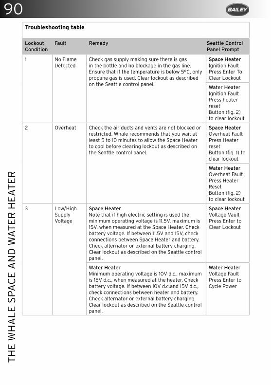
Troubleshooting table
Lockout Condition
Fault Remedy Seattle Control Panel Prompt
1 No Flame Detected
Check gas supply making sure there is gas in the bottle and no blockage in the gas line. Ensure that if the temperature is below 5°C, only propane gas is used. Clear lockout as described on the Seattle control panel.
Space HeaterIgnition Fault Press Enter ToClear Lockout
Water HeaterIgnition FaultPress heater resetButton (fig. 2) to clear lockout
2 Overheat Check the air ducts and vents are not blocked or restricted. Whale recommends that you wait at least 5 to 10 minutes to allow the Space Heater to cool before clearing lockout as described on the Seattle control panel.
Space HeaterOverheat FaultPress Heater resetButton (fig. 1) to clear lockout
Water HeaterOverheat FaultPress Heater ResetButton (fig. 2) to clear lockout
3 Low/High SupplyVoltage
Space HeaterNote that if high electric setting is used the minimum operating voltage is 11.5V, maximum is 15V, when measured at the Space Heater. Check battery voltage. If between 11.5V and 15V, check connections between Space Heater and battery. Check alternator or external battery charging.Clear lockout as described on the Seattle control panel.
Space HeaterVoltage VaultPress Enter to Clear Lockout
Water HeaterMinimum operating voltage is 10V d.c., maximum is 15V d.c., when measured at the heater. Check battery voltage. If between 10V d.c.and 15V d.c., check connections between heater and battery. Check alternator or external battery charging. Clear lockout as described on the Seattle control panel.
Water HeaterVoltage FaultPress Enter toCycle Power
90TH
E W
HA
LE S
PAC
E A
ND
WA
TER
HEA
TER
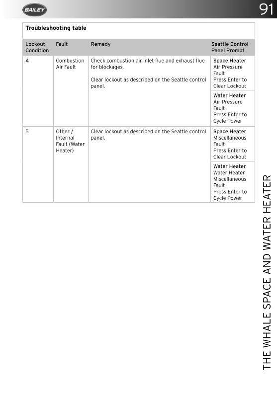
Troubleshooting table
Lockout Condition
Fault Remedy Seattle Control Panel Prompt
4 Combustion Air Fault
Check combustion air inlet flue and exhaust flue for blockages.
Clear lockout as described on the Seattle control panel.
Space HeaterAir Pressure FaultPress Enter toClear Lockout
Water HeaterAir Pressure FaultPress Enter toCycle Power
5 Other / Internal Fault (Water Heater)
Clear lockout as described on the Seattle control panel.
Space HeaterMiscellaneous FaultPress Enter toClear Lockout
Water HeaterWater HeaterMiscellaneous FaultPress Enter toCycle Power
91
THE
WH
ALE
SPA
CE
AN
D W
ATE
R H
EATE
R

360° AVM systemSMART VISION
Smart Vision 360° is an advanced four-camera driver assistance
system. This innovative solution processes the four individual
camera images to form a bird’s eye view of the vehicle, in addition
to panoramic side, front and rear views.
Six different views are selectable through the command switch
mounted on the dashboard, some of which are automatically
selected when the turn indicators or reverse gear are used.
To see what you can’t see
www. .co.uksmartvision360
7" LCD mirror monitor
Full-screen ultra wide-angle front/rear views (selectable with command switch)
01249 401000
www.bailey-parts.co.ukAvailable at:
93
THE
DIG
ITA
L A
NTE
NN
A S
YST
EM
The Digital Antenna System
The Status 550 Digital Antenna System .................................................................... 94
Operating The System .................................................................................................... 94
Fault Finding ..................................................................................................................... 94
Maintenance...................................................................................................................... 95
Technical Data ................................................................................................................. 96

94TH
E D
IGIT
AL
AN
TEN
NA
SY
STEM
The Digital Antenna System
The Status 550 Digital Antenna System
Operating The System
Firstly determine the approximate location of the nearest transmitter and whether the signals are horizontally or vertically polarised. For assistance ask your site operator or check other antennas in the vicinity.
1. Loosen the mast locking collar and raise the antenna.
2. Determine whether the TV transmissions are horizontal or vertical and position accordingly.
3. Switch ON the amplifier and the LED will illuminate and check the gain is set to MIN by rotating the button anti-clockwise.
4. Rotate the antenna:
• RED - poor signal - keep turning.• YELLOW - getting better - slow down.• GREEN - signals located, ready to go.
5. If there is no GREEN increase the gain and repeat the 360 degree rotation.
6. Once the transmitter has been located, increase the gain to MAX.
7. Turn on your TV set and tune in. This will be necessary at all new locations.
Fault Finding
The following are some of the key areas we suggest you check which generally solve the most common problems encountered with the operation of the Status antenna.
Coaxial connections
It is critical that all connections in the system are fitted correctly. Using the diagrams and procedures described, please check all connectors ensuring they are wired correctly. Secondly please ensure only quality plugs have been used.
Coaxial Cable
Sharp bends, kinks and hot surfaces can easily damage coaxial cable and should be avoided. Coaxial cable, if placed in close proximity to electrical cables, transformers or other pieces of electrical equipment, may pick up electrical interference causing picture quality to deteriorate, especially in poor reception areas. Excess cable should be removed and NOT coiled as this may cause picture distortion. An inspection of the routing of the cable is highly recommended to ensure all is correct.
Gain Control
In normal use the button should be rotated clockwise to maximum. In strong signal areas the amplification may need to be reduced. To reduce amplification, rotate the button anti-clockwise until picture quality improves. The button rotates through 270° from MAX to MIN.
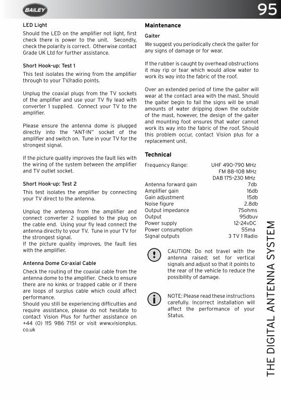
95
THE
DIG
ITA
L A
NTE
NN
A S
YST
EM
LED Light
Should the LED on the amplifier not light, first check there is power to the unit. Secondly, check the polarity is correct. Otherwise contact Grade UK Ltd for further assistance.
Short Hook-up: Test 1
This test isolates the wiring from the amplifier through to your TV/radio points.
Unplug the coaxial plugs from the TV sockets of the amplifier and use your TV fly lead with converter 1 supplied. Connect your TV to the amplifier.
Please ensure the antenna dome is plugged directly into the “ANT-IN” socket of the amplifier and switch on. Tune in your TV for the strongest signal.
If the picture quality improves the fault lies with the wiring of the system between the amplifier and TV outlet socket.
Short Hook-up: Test 2
This test isolates the amplifier by connecting your TV direct to the antenna.
Unplug the antenna from the amplifier and connect converter 2 supplied to the plug on the cable end. Using your fly lead connect the antenna directly to your TV. Tune in your TV for the strongest signal.If the picture quality improves, the fault lies with the amplifier.
Antenna Dome Co-axial Cable
Check the routing of the coaxial cable from the antenna dome to the amplifier. Check to ensure there are no kinks or trapped cable or if there are loops of surplus cable which could affect performance.Should you still be experiencing difficulties and require assistance, please do not hesitate to contact Vision Plus for further assistance on +44 (0) 115 986 7151 or visit www.visionplus.co.uk
Maintenance
Gaiter
We suggest you periodically check the gaiter for any signs of damage or for wear.
If the rubber is caught by overhead obstructions it may rip or tear which would allow water to work its way into the fabric of the roof.
Over an extended period of time the gaiter will wear at the contact area with the mast. Should the gaiter begin to fail the signs will be small amounts of water dripping down the outside of the mast, however, the design of the gaiter and mounting foot ensures that water cannot work its way into the fabric of the roof. Should this problem occur, contact Vision plus for a replacement unit.
Technical
Frequency Range: UHF 490–790 MHz FM 88–108 MHz DAB 175–230 MHzAntenna forward gain 7dbAmplifier gain 16dbGain adjustment 15dbNoise figure 2.8dbOutput impedance 75ohmsOutput 95dbuvPower supply 12–24vDCPower consumption 55maSignal outputs 3 TV 1 Radio
CAUTION: Do not travel with the antenna raised; set for vertical signals and adjust so that it points to the rear of the vehicle to reduce the possibility of damage.
NOTE: Please read these instructions carefully. Incorrect installation will affect the performance of your Status.

96TH
E D
IGIT
AL
AN
TEN
NA
SY
STEM
Signal Symptom Action
Very poor No picture or sound, TV freezing, severe pixilation, break-up and picture drop out.
Check the amplifier gain is set to maximum (rotate clockwise). Check antenna alignment which must be directed at the transmitter. Ensure the antennas polarity is correct, whether horizontal or vertical. Bypass the amplifier by following ‘Short Hook-up: Test 1’.
Poor Moderate pixilation and sound distortion
Medium Minor pixilation, will not receive all channels.
Good Stable picture, good sound quality, will receive all channels.
N/A
Strong Possible pixilation, picture break-up and drop out.
Reduce the amplifier gain (rotate anti-clockwise). Rotate antenna AWAY from the transmitter.
Very strong No picture or sound, TV freezing, severe pixilation, break-up and picture drop out.
Rotate antennal AWAY from the transmitter. Switch OFF the amplifier and turn the gain control to maximum (rotate clockwise).
After performing any of the Actions above you must re-tune your TV
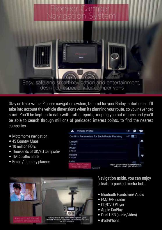
Stay on track with a Pioneer navigation system, tailored for your Bailey motorhome. It’ll Stay on track with a Pioneer navigation system, tailored for your Bailey motorhome. It’ll take into account the vehicle dimensions when its planning your route, so you never get take into account the vehicle dimensions when its planning your route, so you never get stuck. You’ll be kept up to date with traffic reports, keeping you out of jams and you’ll stuck. You’ll be kept up to date with traffic reports, keeping you out of jams and you’ll be able to search through millions of preloaded interest points, to find the nearest be able to search through millions of preloaded interest points, to find the nearest campsites.campsites.
• Motorhome navigation• Motorhome navigation• 45 Country Maps• 45 Country Maps• 10 million POI’s• 10 million POI’s• Thousands of UK/EU campsites• Thousands of UK/EU campsites• TMC traffic alerts• TMC traffic alerts• Route / itinerary planner• Route / itinerary planner
Navigation aside, you can enjoy Navigation aside, you can enjoy a feature packed media hub.a feature packed media hub.
• Bluetooth Handsfree/ Audio• Bluetooth Handsfree/ Audio• FM/DAB+ radio• FM/DAB+ radio• CD/DVD Player• CD/DVD Player• Apple CarPlay• Apple CarPlay• Dual USB (audio/video)• Dual USB (audio/video)• iPod/iPhone• iPod/iPhone

98TH
E M
EDIA
PA
CK
The Media Pack
Full Integration .................................................................................................................99
HD digital television with DVD ..................................................................................... 100
Media Pack Plus .............................................................................................................. 100
Bespoke Motorhome Sat Nav ...................................................................................... 100
Apple Car Play ................................................................................................................. 100
Aha Radio ......................................................................................................................... 100
Android Auto ................................................................................................................... 100
MirrorLink .......................................................................................................................... 101
Expanded Bluetooth Capability ................................................................................... 101
FLAC file support ............................................................................................................. 101
MIXTRAX ............................................................................................................................ 101
Dual camera inputs ........................................................................................................ 101
Built-in Auto EQ and Time Alignment ........................................................................ 101
13-Band Graphic Equalizer ............................................................................................ 101
Customisable User Interface ........................................................................................ 101
Dual USB Inputs ............................................................................................................... 101
Door And Lounge Speakers ......................................................................................... 101
Otone BluWall Portable Speaker ................................................................................. 102
Bespoke Otone Speaker Bracket ................................................................................ 102
Bracket Installation ........................................................................................................ 103
The Head Unit .................................................................................................................. 104
Quick Set Up .................................................................................................................... 104
Navigation And Maps ..................................................................................................... 105
99
THE
MED
IA P
AC
K
The Media Pack
The Media Pack and Media Pack Plus are new factory fit options for the 2017 autograph motorhome range. Created in conjunction with sound technicians, a project undertaken by Bailey to find the correct products and positioning which best suit the interior features of the new Autograph range. The two pack options enable you to choose the features within your motorhome to best suit your media needs.
The Media Pack includes:
• Waeco reversing camera & screen• Status 550 telescopic directional digital
television aerial• Front 19” HD Avtex digital television with
DVD player (12v or 240v).
The Media Pack Plus includes:
• Waeco reversing camera• Status 550 telescopic directional digital
television aerial • Front 19” HD Avtex digital television with
DVD player (12v or 240v).• Rear 24” HD Avtex TV with DVD player (12v
or 240v)• Branded door & lounge speakers,• Branded portable Bluetooth awning speaker• 6.5” Touch-Screen branded head-unit
featuring:
> Bespoke motorhome Sat Nav
> Apple CarPlay
> DAB+ digital radio
> Bluetooth audio streaming
> 2 rear USB connection points
> Anti-theft protection
> Reversing camera screen function
Full Integration
Every aspect of your motorhome media has been thought of whilst designing this fully integrated system to utilise the media components installed in your motorhome. The head unit serves as the main controller of the system and allows for all aspects of the sound to be customised, controlled or switched on or off.
Whilst driving, the system provides sound from many different media sources: CD, Radio, Digital Radio, Internet radio, Bluetooth or USB, all of which can be heard through the door speakers in your cab. Rear passengers can also enjoy the sound clearly through the lounge speakers. Sound levels in both areas can be easily adjusted to suit your requirements.
Whilst on site, the full system can be enjoyed; switch the sound source to the Otone speaker to watch a movie with full cinema style sound through the Media Pack Plus system, enhance sound and volume to suit listening in all weather conditions, unplug the speaker and it becomes a fully portable Bluetooth speaker. Perfect for evenings out underneath the awning or even a picnic at the beach.
All media pack components use power from the leisure battery which means you have piece of mind that if you drain the battery whilst not hooked up, the engine will still start using the cab battery.
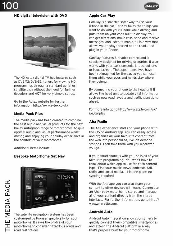
100TH
E M
EDIA
PA
CK
HD digital television with DVD
The HD Avtex digital TV has features such as DVB-T2/DVB-S2 tuners for viewing HD programmes through a standard aerial or satellite dish without the need for further decoders and AQT for very simple set up.
Go to the Avtex website for further information: http://www.avtex.co.uk/
Media Pack Plus
The media pack has been created to combine the best audio and visual products for the new Bailey Autograph range of motorhomes, to give optimal audio and visual performance whilst driving and enjoying your holiday experience in the comfort of your motorhome.
Additional items include:
Bespoke Motorhome Sat Nav
The satellite navigation system has been customised by Pioneer specifically for your motorhome. It saves the profile of your motorhome to consider hazardous roads and road restrictions.
Apple Car Play
CarPlay is a smarter, safer way to use your iPhone in the car. CarPlay takes the things you want to do with your iPhone while driving and puts them on your car’s built-in display. You can get directions, make calls, send and receive messages, and listen to music, all in a way that allows you to stay focused on the road. Just plug in your iPhone.
CarPlay features Siri voice control and is specially designed for driving scenarios. It also works with your car’s controls, knobs, buttons or touchscreen. The apps themselves have been re-imagined for the car, so you can use them while your eyes and hands stay where they belong.
By connecting your phone to the head unit it allows the head unit to update vital information such as new road layouts and traffic situations ahead.
For more info go to http://www.apple.com/uk/ios/carplay
Aha Radio
The Aha experience starts on your phone with the iOS or Android app. You can easily access and organize all your favourite content from the web into personalized, live, on-demand stations. Then take them with you wherever you go.
If your smartphone is with you, so is all of your favourite programming. You won’t have to think about which app to use for each content type. Find your music, news, podcasts, talk radio, and social media, all in one place, no syncing required.
With the Aha app you can also share your content to other devices with ease. Connect to an Aha-ready motorhome stereo and manage all of your content directly from the stereo interface. For further information, go to http://www.aharadio.com.
Android Auto
Android Auto integration allows consumers to quickly connect their compatible smartphones and extend the Android platform in a way that’s purpose-built for your motorhome.
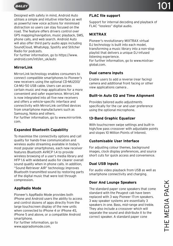
101
THE
MED
IA P
AC
K
Designed with safety in mind, Android Auto utilises a simple and intuitive interface as well as powerful new voice actions for minimised distraction so users can stay focused on the road. The feature offers drivers control over GPS mapping/navigation, music playback, SMS, phone calls, and web search. Android Auto will also offer third party audio apps including SoundCloud, WhatsApp, Spotify and Stitcher Radio for podcasts. For further information, go to https://www.android.com/intl/en_uk/auto
MirrorLink
MirrorLink technology enables consumers to connect compatible smartphones to Pioneer’s new receivers using the optional CD-MU200/CA-MU-50 USB cable. Users can access certain music and map applications for a more convenient and safer experience. MirrorLink is now integrated into all five new receivers and offers a vehicle-specific interface and connectivity with MirrorLink certified devices from smartphone manufacturers such as Samsung, Nokia and others.For further information, go to www.mirrorlink.com. Expanded Bluetooth Capability
To maximise the connectivity options and call quality for hands-free communication and wireless audio streaming available in today’s most popular smartphones, each new receiver features Bluetooth AVRCP 1.4 to provide wireless browsing of a user’s media library and HFP 1.6 with wideband audio for clearer overall sound quality when in phone calls. In addition, “Sound Retriever AIR” technology improves Bluetooth transmitted sound by restoring parts of the digital music that were lost through compression.
AppRadio Mode
Pioneer’s AppRadio Mode provides both iPhone and Android users the ability to access and control dozens of apps directly from the large touchscreen display of the new units when connected to iPhone 4 or iPhone 4S, iPhone 5 and above, or a compatible Android smartphone.For further information, go to www.appradiomode.com.
FLAC file support
Support for internal decoding and playback of FLAC “lossless” digital audio.
MIXTRAX
Pioneer’s revolutionary MIXTRAX virtual DJ technology is built into each model, transforming a music library into a non-stop playlist that delivers a unique DJ-infused listening experience.For further information, go to www.mixtrax-global.com.
Dual camera inputs
Enable users to add a reverse (rear facing) camera and additional front facing or other view applications camera .
Built-in Auto EQ and Time Alignment
Provides tailored audio adjustments specifically for the car and user preference using the optional microphone.
13-Band Graphic Equalizer
With touchscreen swipe settings and built-in high/low pass crossover with adjustable points and slopes 10 Million Points of Interest.
Customisable User Interface
For adjusting colour themes, background images, clock display preferences, and source short cuts for quick access and convenience.
Dual USB Inputs
For audio video playback from USB as well as smartphone connectivity and charging.
Door And Lounge Speakers
The standard paper cone speakers that come standard with the Peugeot cab have been replaced with 3 way Pioneer 17cm speakers. 3 way speaker systems are essentially 3 speakers in one. Bass, mid-range and treble. They also include a crossover which will separate the sound and distribute it to the correct speaker. A standard paper cone
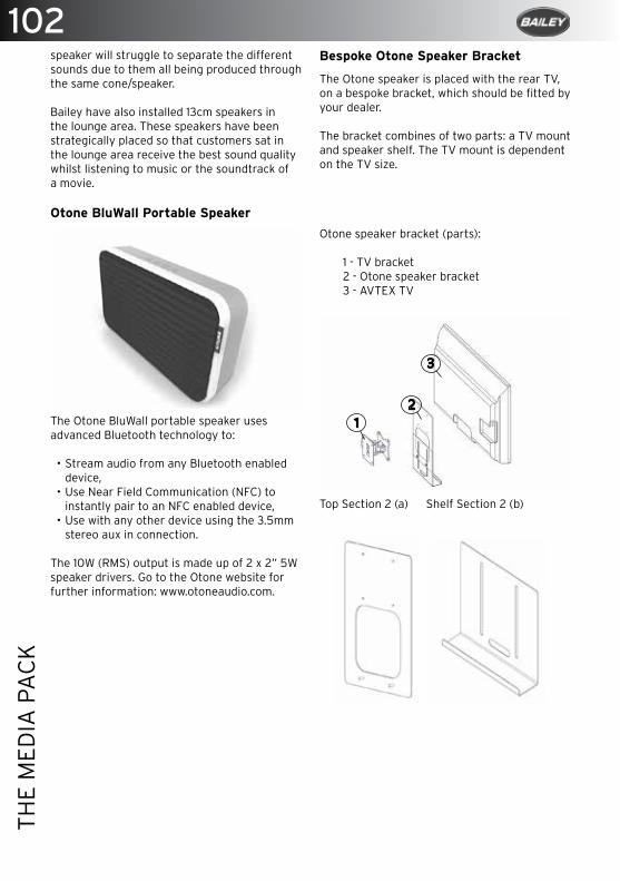
102TH
E M
EDIA
PA
CK
speaker will struggle to separate the different sounds due to them all being produced through the same cone/speaker.
Bailey have also installed 13cm speakers in the lounge area. These speakers have been strategically placed so that customers sat in the lounge area receive the best sound quality whilst listening to music or the soundtrack of a movie.
Otone BluWall Portable Speaker
The Otone BluWall portable speaker uses advanced Bluetooth technology to:
• Stream audio from any Bluetooth enabled device,
• Use Near Field Communication (NFC) to instantly pair to an NFC enabled device,
• Use with any other device using the 3.5mm stereo aux in connection.
The 10W (RMS) output is made up of 2 x 2” 5W speaker drivers. Go to the Otone website for further information: www.otoneaudio.com.
Bespoke Otone Speaker Bracket
The Otone speaker is placed with the rear TV, on a bespoke bracket, which should be fitted by your dealer.
The bracket combines of two parts: a TV mount and speaker shelf. The TV mount is dependent on the TV size.
Otone speaker bracket (parts):
1 - TV bracket2 - Otone speaker bracket3 - AVTEX TV
Top Section 2 (a) Shelf Section 2 (b)

103
THE
MED
IA P
AC
K
Bracket Installation
1. Connect brackets a & b by placing the threaded lugs provided through both section slots (b), into the holes of section a. Secure with nuts provided.
2. The Otone speaker bracket assembly sits between the back face of the TV and the TV wall bracket.
3. Attach to the back of the TV using the four bolts provided.
4. Loosen nuts to adjust the Otone shelf section (b) to the correct size for fitting the Otone speaker.
5. To integrate the speaker with the media system, insert the right angled AUX plug though the slot in the bottom of the shelf section and connect to the Otone speaker. The spare straight lead should be connected to the headphone output on your TV.
Please Note: The AUX plug behind located behind your front TV should also be plugged into the headphone output. This can be found on the side of the TV.
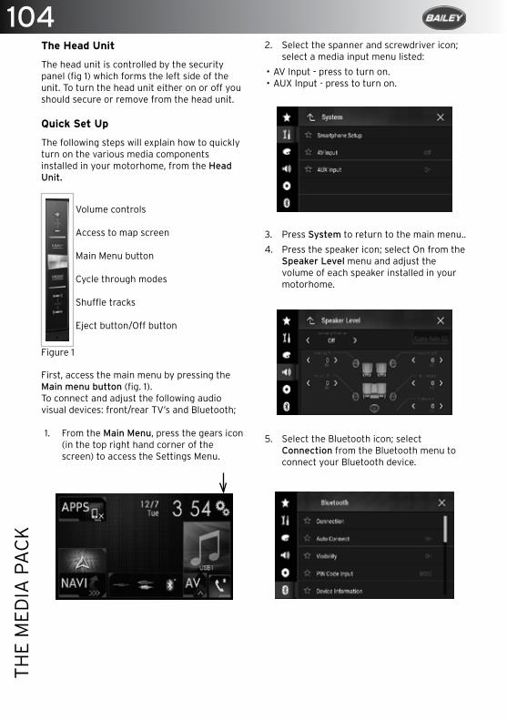
104TH
E M
EDIA
PA
CK
The Head Unit
The head unit is controlled by the security panel (fig 1) which forms the left side of the unit. To turn the head unit either on or off you should secure or remove from the head unit.
Quick Set Up
The following steps will explain how to quickly turn on the various media components installed in your motorhome, from the Head Unit.
First, access the main menu by pressing the Main menu button (fig. 1).To connect and adjust the following audio visual devices: front/rear TV’s and Bluetooth;
1. From the Main Menu, press the gears icon (in the top right hand corner of the screen) to access the Settings Menu.
Volume controls
Access to map screen
Main Menu button
Cycle through modes
Shuffle tracks
Eject button/Off button
Figure 1
2. Select the spanner and screwdriver icon; select a media input menu listed:
• AV Input - press to turn on.• AUX Input - press to turn on.
3. Press System to return to the main menu..
4. Press the speaker icon; select On from the Speaker Level menu and adjust the volume of each speaker installed in your motorhome.
5. Select the Bluetooth icon; select Connection from the Bluetooth menu to connect your Bluetooth device.
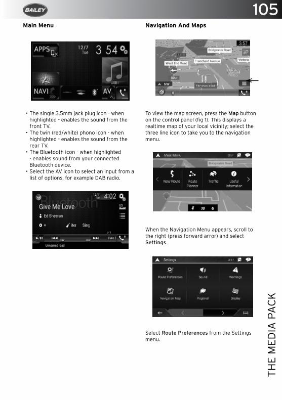
105
THE
MED
IA P
AC
K
Navigation And Maps
To view the map screen, press the Map button on the control panel (fig 1). This displays a realtime map of your local vicinity; select the three line icon to take you to the navigation menu.
When the Navigation Menu appears, scroll to the right (press forward arror) and select Settings.
Select Route Preferences from the Settings menu.
Main Menu
• The single 3.5mm jack plug icon - when highlighted - enables the sound from the front TV.
• The twin (red/white) phono icon - when highlighted - enables the sound from the rear TV.
• The Bluetooth icon - when highlighted - enables sound from your connected Bluetooth device.
• Select the AV icon to select an input from a list of options, for example DAB radio.
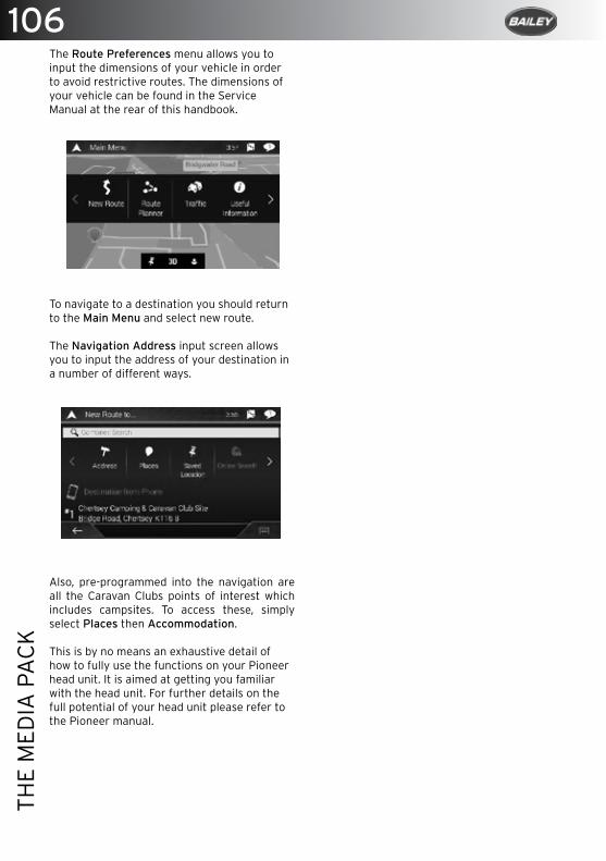
106TH
E M
EDIA
PA
CK
The Route Preferences menu allows you to input the dimensions of your vehicle in order to avoid restrictive routes. The dimensions of your vehicle can be found in the Service Manual at the rear of this handbook.
To navigate to a destination you should return to the Main Menu and select new route.
The Navigation Address input screen allows you to input the address of your destination in a number of different ways.
Also, pre-programmed into the navigation are all the Caravan Clubs points of interest which includes campsites. To access these, simply select Places then Accommodation.
This is by no means an exhaustive detail of how to fully use the functions on your Pioneer head unit. It is aimed at getting you familiar with the head unit. For further details on the full potential of your head unit please refer to the Pioneer manual.

Did
you k
no
w th
at yo
ur n
ew
Baile
y mo
torh
om
e h
as
pre
-insta
lled
cab
ling
to fi
t a W
AE
CO
reve
rsing
cam
era
?
WA
EC
O R
eversing C
amera
System
RV
S 550W
• For 12 volt and 24 volt operation
• US
B connection for charging M
P3 players etc.
• Easylink m
onitor mount, for easy rem
oval• LE
D b
ackground illumination
• Colour cam
era available in white or silver
• 5” colour LCD
monitor
• 2 year warranty
Fo
r furth
er details p
lease
con
tact you
r local B
ailey dealer
GE
T A
CLE
AR
ER
VIE
W
Quick monitor rem
oval
108TH
E TH
ETFO
RD
DU
PLE
X O
VEN
, GR
ILL
AN
D H
OB
The Thetford Duplex Oven, Grill and Hob
The Duplex Oven and Grill ............................................................................................ 109
Provision of Ventilation ................................................................................................. 109
Oven And Grill Controls ................................................................................................ .109
Temperature Control ........................................................................................................ 111
Thetford Duel Fuel Gas Hob ........................................................................................... 111
Thetford 330 Series Hob ................................................................................................. 111
Operation ............................................................................................................................ 111
Gas Burners....................................................................................................................... 112
Maintenance .................................................................................................................... 112
Servicing ............................................................................................................................ 113
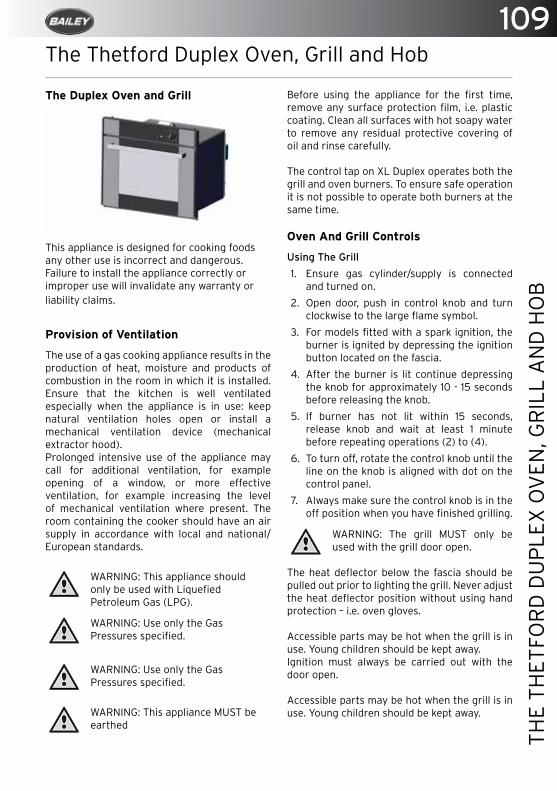
109
THE
THET
FOR
D D
UP
LEX
OV
EN, G
RIL
L A
ND
HO
B
The Thetford Duplex Oven, Grill and Hob
The Duplex Oven and Grill
This appliance is designed for cooking foods any other use is incorrect and dangerous. Failure to install the appliance correctly or improper use will invalidate any warranty or liability claims.
Provision of Ventilation
The use of a gas cooking appliance results in the production of heat, moisture and products of combustion in the room in which it is installed. Ensure that the kitchen is well ventilated especially when the appliance is in use: keep natural ventilation holes open or install a mechanical ventilation device (mechanical extractor hood).Prolonged intensive use of the appliance may call for additional ventilation, for example opening of a window, or more effective ventilation, for example increasing the level of mechanical ventilation where present. The room containing the cooker should have an air supply in accordance with local and national/European standards.
WARNING: This appliance should only be used with Liquefied Petroleum Gas (LPG).
WARNING: Use only the Gas Pressures specified.
WARNING: Use only the Gas Pressures specified.
WARNING: This appliance MUST be earthed
Before using the appliance for the first time, remove any surface protection film, i.e. plastic coating. Clean all surfaces with hot soapy water to remove any residual protective covering of oil and rinse carefully.
The control tap on XL Duplex operates both the grill and oven burners. To ensure safe operation it is not possible to operate both burners at the same time.
Oven And Grill Controls
Using The Grill
1. Ensure gas cylinder/supply is connected and turned on.
2. Open door, push in control knob and turn clockwise to the large flame symbol.
3. For models fitted with a spark ignition, the burner is ignited by depressing the ignition button located on the fascia.
4. After the burner is lit continue depressing the knob for approximately 10 - 15 seconds before releasing the knob.
5. If burner has not lit within 15 seconds, release knob and wait at least 1 minute before repeating operations (2) to (4).
6. To turn off, rotate the control knob until the line on the knob is aligned with dot on the control panel.
7. Always make sure the control knob is in the off position when you have finished grilling.
WARNING: The grill MUST only be used with the grill door open.
The heat deflector below the fascia should be pulled out prior to lighting the grill. Never adjust the heat deflector position without using hand protection – i.e. oven gloves.
Accessible parts may be hot when the grill is in use. Young children should be kept away.Ignition must always be carried out with the door open.
Accessible parts may be hot when the grill is in use. Young children should be kept away.
110TH
E TH
ETFO
RD
DU
PLE
X O
VEN
, GR
ILL
AN
D H
OB
On first use of the grill, it should be heated for about 20 minutes to eliminate any residual factory lubricants that might impart unpleasant smells to the food being cooked. A non-toxic smoke may occur when using for the first time, open any windows and turn on mechanical ventilators to help remove the smoke.
Although the grill heats up quickly, it is recommended that a few minutes preheat be allowed.
It is normal for the flames on this burner to develop yellow tips as it heats up.
Depending on the food to be cooked, the correct grilling height can be achieved by inverting the pan trivet into either the high or low position.
Using The Oven
1. Ensure gas cylinder/supply is connected and turned on.
2. Open door, push in control knob & turn to full rate (Gas Mark 9, 240°C).
3. For models fitted with a spark ignition. the burner is ignited by depressing the ignition button located on the fascia.
4. After the burner is lit continue depressing the knob for approximately 10 - 15 seconds.
5. Release the knob and turn to required heat setting.
6. If the burner has not lit within 15 seconds, release knob and wait at least 1 minute before repeating operations (2) to (5).
7. Place the oven shelf in the required position and close the door.
8. Although the oven heats up quickly a 10 minute preheat is recommended. The oven should reach full temperature in about 15-20mins.
9. To turn off, rotate the control knob until the line on the knob is aligned with the dot on the control panel.
10. Always make sure the control knob is in the off position when you have finished.
The oven shelf has been designed to allow good circulation at the rear of the oven. A raised bar at the rear of the shelf prevents trays or dishes
making contact with the back of the oven. To remove a shelf, pull forward until it stops, raise at front and remove. Installation of a shelf is the reverse of this procedure.
Before using your oven for the first time we recommend cleaning all surfaces with hot soapy water. Light the oven and set control knob to gas mark 5 (200°C). Heat the oven for about 30 minutes to eliminate any residual factory lubricants that might impart unpleasant smells to cooked food.
A non-toxic smoke may occur during this procedure, open any windows and turn on mechanical ventilators to help remove the smoke.
WARNING: Ignition must always be carried out with the door open.
WARNING: Accessible parts may be hot when the grill is in use. Young children should be kept away.
WARNING:The pans and trays supplied with this appliance are the maximum sizes recommended for use. Larger pans and trays may restrict good circulation of heat, increasing cooking times.
NOTE: The appliance is fitted with a fan cooling system. The cooling fan will automatically switch on after lighting the grill or oven burner, and automatically switch off a few minutes after the burner is extinguished, when the front of the appliance has cooled sufficiently.
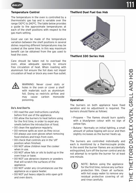
111
THE
THET
FOR
D D
UP
LEX
OV
EN, G
RIL
L A
ND
HO
B
Temperature Control
The temperature in the oven is controlled by a thermostatic gas tap and is variable over the range 130°C to 240°C. The table below provides a guide to the approximate temperatures at each of the shelf positions with respect to the gas mark setting.
Good use can be made of the temperature variation between the shelf positions in several dishes requiring different temperatures may be cooked at the same time. In this way maximum benefit can be obtained from the gas used to heat the oven.
Care should be taken not to overload the oven, allow adequate spacing to ensure free circulation of heat. When roasting with aluminium foil ensure the foil does not impair circulation of heat or block any oven flue outlet.
WARNING: Never cover slots or holes in the oven or cover a shelf with materials such as aluminium foil. Doing so restricts airflow and may cause carbon monoxide poisoning.
Do’s And Don’ts
• DO read the user instructions carefully before first use of the appliance.
• DO allow the burners to heat before using for the first time, in order to expel any smells before the introduction of food.
• DO clean the appliance regularly.• DO remove spills as soon as they occur.• DO always use oven gloves when removing
food shelves and trays from oven.• DO check that controls are in the ‘off’
position when finished.• DO NOT allow children near the cooker
when in use. • DO NOT allow fats or oils to build up in the
oven trays or base.• DO NOT use abrasive cleaners or powders
that will scratch the surfaces of the appliance.
• DO NOT under any circumstances use the appliance as a space heater.
• DO NOT put heavy objects onto open grill and oven doors.
Thetford Duel Fuel Gas Hob
Thetford 330 Series Hob
Operation
The burners on both appliance have fixed aeration and no adjustment is required. The burners should flame as follows:
> Propane - The flames should burn quietly with a blue/green colour with no sign of yellow tips.
> Butane - Normally on initial lighting, a small amount of yellow tipping will occur and then slightly increases as the burner heats up.
The burners are controlled individually and each is monitored by a thermocouple probe. In the event the burner flames are accidentally extinguished, turn off the burner control and do not attempt to re-ignite the burner for at least one minute.
NOTE: Before using the appliance for the first time, remove any surface protection film. Clean all surfaces with hot soapy water to remove any residual protective covering of oil and rinse carefully.
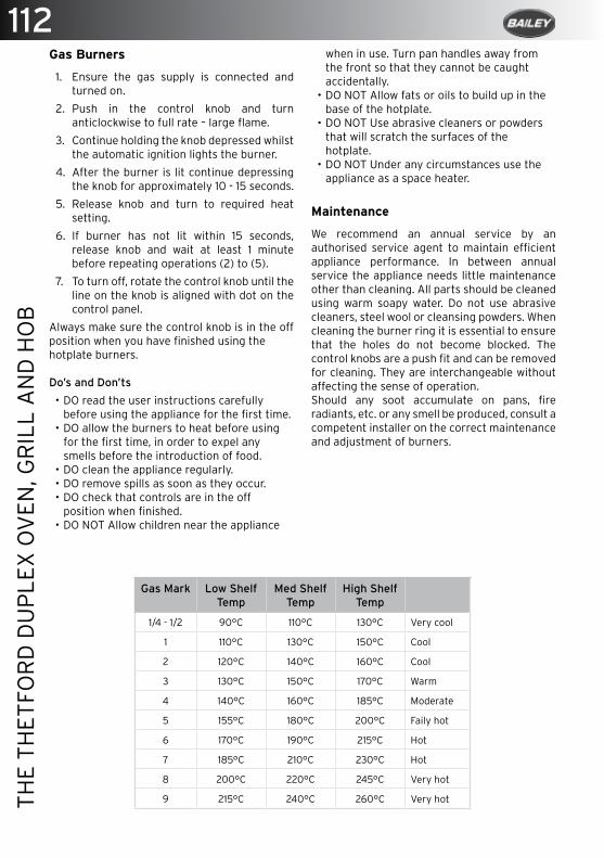
112TH
E TH
ETFO
RD
DU
PLE
X O
VEN
, GR
ILL
AN
D H
OB
Gas Burners
1. Ensure the gas supply is connected and turned on.
2. Push in the control knob and turn anticlockwise to full rate – large flame.
3. Continue holding the knob depressed whilst the automatic ignition lights the burner.
4. After the burner is lit continue depressing the knob for approximately 10 - 15 seconds.
5. Release knob and turn to required heat setting.
6. If burner has not lit within 15 seconds, release knob and wait at least 1 minute before repeating operations (2) to (5).
7. To turn off, rotate the control knob until the line on the knob is aligned with dot on the control panel.
Always make sure the control knob is in the off position when you have finished using thehotplate burners.
Do’s and Don’ts
• DO read the user instructions carefully before using the appliance for the first time.
• DO allow the burners to heat before using for the first time, in order to expel any smells before the introduction of food.
• DO clean the appliance regularly.• DO remove spills as soon as they occur.• DO check that controls are in the off
position when finished.• DO NOT Allow children near the appliance
when in use. Turn pan handles away from the front so that they cannot be caught accidentally.
• DO NOT Allow fats or oils to build up in the base of the hotplate.
• DO NOT Use abrasive cleaners or powders that will scratch the surfaces of the hotplate.
• DO NOT Under any circumstances use the appliance as a space heater.
Maintenance
We recommend an annual service by an authorised service agent to maintain efficient appliance performance. In between annual service the appliance needs little maintenance other than cleaning. All parts should be cleaned using warm soapy water. Do not use abrasive cleaners, steel wool or cleansing powders. When cleaning the burner ring it is essential to ensure that the holes do not become blocked. The control knobs are a push fit and can be removed for cleaning. They are interchangeable without affecting the sense of operation.Should any soot accumulate on pans, fire radiants, etc. or any smell be produced, consult a competent installer on the correct maintenance and adjustment of burners.
Gas Mark Low Shelf Temp
Med ShelfTemp
High ShelfTemp
1/4 - 1/2 90°C 110°C 130°C Very cool
1 110°C 130°C 150°C Cool
2 120°C 140°C 160°C Cool
3 130°C 150°C 170°C Warm
4 140°C 160°C 185°C Moderate
5 155°C 180°C 200°C Faily hot
6 170°C 190°C 215°C Hot
7 185°C 210°C 230°C Hot
8 200°C 220°C 245°C Very hot
9 215°C 240°C 260°C Very hot

113
THE
THET
FOR
D D
UP
LEX
OV
EN, G
RIL
L A
ND
HO
B
Servicing
All servicing must be carried out by an approved competent person. Before any service work is started the appliance should have been left to cool and be disconnected from both the gas and electrical supplies. After each service the appliance must be checked for gas soundness.
For service, please contact your authorised local Service Agent giving details of the model and serial number on the data badge plus date of purchase.
WARNING: This appliance must not be modified or adjusted unless authorized and carried out by the manufacturer or his representative. No parts other than those supplied by the manufacturer should be used on this appliance.
WARNING: If the supply cord is damaged, it must only be replaced by the manufacturer or his representative in order to avoid a hazard.

114TH
E M
ICR
OW
AVE
OV
EN -
DA
EWO
O K
OR
-6L5
R
The Microwave Oven - Daewoo KOR-6L5R
Important Safety Instructions: ..................................................................................... 115
Microwave Oven ............................................................................................................... 116
Remote Controller ........................................................................................................... 116
Operation Procedure ...................................................................................................... 117
Controls .............................................................................................................................. 117
Weight Defrosting ............................................................................................................ 117
AUTO COOK ...................................................................................................................... 119
How To Stop the Oven While the Oven is Operating ............................................... 119
Care of Your Microwave Oven...................................................................................... 120
Glass Tray ......................................................................................................................... 120
Care and Cleaning .......................................................................................................... 120
Questions and Answers .................................................................................................. 121
Cooking Instructions ...................................................................................................... 122
Defrosting Guide ............................................................................................................. 122
Specification .................................................................................................................... 123
Utensil Guide .................................................................................................................... 124
115
THE
MIC
RO
WAV
E O
VEN
- D
AEW
OO
KO
R-6
L5R
The Microwave Oven - Daewoo KOR-6L5R Important Safety Instructions:
1. Do not use the oven for any reason other than food preparation.
2. Do not use the oven when empty, this could damage the oven.
3. Do not use the oven cavity for any type of storage.
4. Do not operate the oven without the glass tray in place. Be sure it is sitting properly on the rotating base.
5. Make sure you remove caps or lids prior to cooking when you cook food sealed in bottles.
6. Do not put foreign material between the oven surface and door. It could result in excessive leakage of microwave energy.
7. Do not use recycled paper products for cooking. They may contain impurities which could cause sparks and/or fires when used during cooking.
8. Do not pop popcorn unless popped in a microwave approved popcorn popper or unless it’s commercially packaged and recommended especially for microwave ovens. Microwave popped corn produces a lower yield than conventional popping; there will be a number of unpopped kernels. Do not use oil unless specified by the manufacturer.
9. Do not cook any food surrounded by a membrane, such as egg yolks, potatoes, chicken livers, etc., without first piercing them several times with a fork.
10. Do not pop popcorn longer than the manufacturer’s directions. (popping time is generally below 3 minutes). Longer cooking does not yield more popped corn, it can cause scorching and fire. Also, the cooking tray can become too hot to handle or may break.
11. If smoke is observed, switch off or unplug the appliance and keep the door closed in order to stifle any flames.
12. When heating food in plastic or paper containers, keep an eye on the oven due to the possibility of ignition.
13. The contents of feeding bottles and baby food jars shall be stirred or shaken and the
temperature checked before consumption, in order to avoid burns.
14. Always test the temperature of food or drink which has been heated in a microwave oven before you give it to somebody, especially to children or elderly people. This is important because things which have been heated in a microwave oven carry on getting hotter even though the microwave oven cooking has stopped.
15. Eggs in their shell and whole hard-boiled eggs should not be heated in microwave ovens since they may explode, even after microwave heating has ended.
16. Keep the wave guide cover clean at all times. Wipe the oven interior with a soft damp cloth after each use. If you leave grease or fat anywhere in the cavity it may overheat, smoke or even catch fire when next using the oven.
17. Never heat oil or fat for deep frying as you cannot control the temperature and doing so may lead to overheating and fire.
18. Liquids, such as water, coffee, or tea are able to be overheated beyond the boiling point without appearing to be boiling due to surface tension of the liquid. Visible bubbling or boiling when the container is removed from the microwave oven is not always present. THIS COULD RESULT IN VERY HOT LIQUIDS SUDDENLY BOILING OVER WHEN A SPOON OR OTHER UTENSIL IS INSERTED INTO THE LIQUID. To reduce the risk of injury to persons:
a. Do not overheat the liquid.
b. Do not use straight-sided containers with narrow necks.
c. After heating, allow the container to stand in the microwave oven for a short time before removing the container.
19. Children should be supervised to ensure that they do not play with the appliance.
20. Only use utensils that are suitable for use in microwave ovens.
21. Microwave heating of beverages can result in delayed eruptive boiling, therefore care must be taken when handling the container.

116TH
E M
ICR
OW
AVE
OV
EN -
DA
EWO
O K
OR
-6L5
R
Microwave Oven
1. Door latch - When the door is closed, it will automatically lock. If the door is opened while the oven is operating, the magnetron will automatically shut off.
2. Door seal - The door seal surfaces prevent microwaves escaping from the oven cavity.
3. Oven cavity.
4. Oven lamp - Automatically turns on during oven operating.
5. Safety interlock system.
6. Control panel.
7. Wave guide cover - Protects the microwave outlet from splashes of cooking foods.
8. Roller guide - This must always be used for cooking, together with the glass cooking tray.
9. Coupler - This fits over the shaft in the centre of the oven cavity floor. This is to remain in the oven for all cooking.
10. Glass cooking tray - Made of special heat resistant glass. The tray must always be in proper position before operating. Do not cook food directly on the tray.
11. Viewing screen - Allows viewing of food. The screen is designed so that light can pass through, but not the microwave.
12. Door open button - To open the door push the door open button.
Remote Controller
1. DISPLAY - Cooking time, power level are displayed.
2. AUTO COOK - Used to cook or reheat many of favourite food.
3. WEIGHT DEFROST - Used to defrost foods by weight.
4. TIME DEFROST - Used to defrost foods by time.
5. POWER - Used to set power level.
6. ONE TOUCH COOK - Used to cook or reheat specific quantities of food.
7. TIME SET BUTTON - Used to set the cooking time and weight.
8. STOP/CLEAR - Used to stop the oven operation or to delete the cooking data.
9. START/+30 SEC - Used to start the oven and also used to set a reheat time.
10. Eco - Used to turn the AC power on the oven.
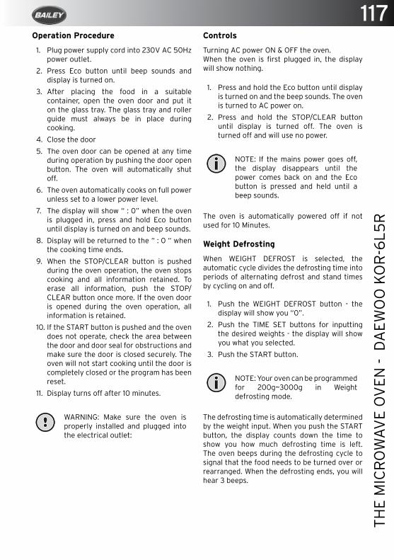
117
THE
MIC
RO
WAV
E O
VEN
- D
AEW
OO
KO
R-6
L5R
Operation Procedure
1. Plug power supply cord into 230V AC 50Hz power outlet.
2. Press Eco button until beep sounds and display is turned on.
3. After placing the food in a suitable container, open the oven door and put it on the glass tray. The glass tray and roller guide must always be in place during cooking.
4. Close the door
5. The oven door can be opened at any time during operation by pushing the door open button. The oven will automatically shut off.
6. The oven automatically cooks on full power unless set to a lower power level.
7. The display will show “ : 0” when the oven is plugged in, press and hold Eco button until display is turned on and beep sounds.
8. Display will be returned to the “ : 0 “ when the cooking time ends.
9. When the STOP/CLEAR button is pushed during the oven operation, the oven stops cooking and all information retained. To erase all information, push the STOP/CLEAR button once more. If the oven door is opened during the oven operation, all information is retained.
10. If the START button is pushed and the oven does not operate, check the area between the door and door seal for obstructions and make sure the door is closed securely. The oven will not start cooking until the door is completely closed or the program has been reset.
11. Display turns off after 10 minutes.
WARNING: Make sure the oven is properly installed and plugged into the electrical outlet:
Controls
Turning AC power ON & OFF the oven.When the oven is first plugged in, the display will show nothing.
1. Press and hold the Eco button until display is turned on and the beep sounds. The oven is turned to AC power on.
2. Press and hold the STOP/CLEAR button until display is turned off. The oven is turned off and will use no power.
NOTE: If the mains power goes off, the display disappears until the power comes back on and the Eco button is pressed and held until a beep sounds.
The oven is automatically powered off if not used for 10 Minutes.
Weight Defrosting
When WEIGHT DEFROST is selected, the automatic cycle divides the defrosting time into periods of alternating defrost and stand times by cycling on and off.
1. Push the WEIGHT DEFROST button - the display will show you “0”.
2. Push the TIME SET buttons for inputting the desired weights - the display will show you what you selected.
3. Push the START button.
NOTE: Your oven can be programmed for 200g~3000g in Weight defrosting mode.
The defrosting time is automatically determined by the weight input. When you push the START button, the display counts down the time to show you how much defrosting time is left. The oven beeps during the defrosting cycle to signal that the food needs to be turned over or rearranged. When the defrosting ends, you will hear 3 beeps.
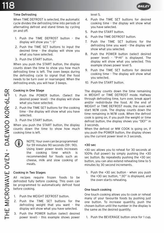
118TH
E M
ICR
OW
AVE
OV
EN -
DA
EWO
O K
OR
-6L5
R
Time Defrosting
When TIME DEFROST is selected, the automatic cycle divides the defrosting time into periods of alternating defrost and stand times by cycling on and off.
1. Push the TIME DEFROST button - the display will show you “: 0”
2. Push the TIME SET buttons to input the desired time - the display will show you what you have selected.
3. Push the START button.
When you push the START button, the display counts down the time to show you how much defrosting time is left. The oven beeps during the defrosting cycle to signal that the food needs to be turn over or rearranged. When the defrosting ends, you will hear 3 beeps.
Cooking in One Stage
1. Push the POWER button. (Select the desired power level) - the display will show what you have selected.
2. Push the TIME SET buttons for the cooking time - the display will show what you have selected.
3. Push the START button.
When you push the START button, the display counts down the time to show how much cooking time is left.
NOTE: Your oven can be programmed for 59 minutes 90 seconds (59 : 90). Using lower power levels increases the cooking time which is recommended for foods such as cheese, milk and slow cooking of meats.
Cooking in Two Stages
All recipes require frozen foods to be defrosted fully before cooking. This oven can be programmed to automatically defrost food before cooking.
1. Push the WEIGHT DEFROST button.
2. Push the TIME SET buttons for the defrosting weight that you want - the display will show what you have selected.
3. Push the POWER button (select desired power level) - this example shows power
level 5.
4. Push the TIME SET buttons for desired cooking time - the display will show what you have selected.
5. Push the START button.
6. Push the TIME DEFROST button.
7. Push the TIME SET buttons for the defrosting time you want - the display will show what you selected.
8. Push the POWER button (select desired power level) - “P-HI” is displayed. The display will show what you selected. This example shows power level 5.
9. Push the TIME SET buttons for desired cooking time - The display will show what you selected.
10. Push the START button.
The display counts down the time remaining in WEIGHT or TIME DEFROST mode. Halfway through defrosting time, turn over, break apart and/or redistribute the food. At the end of WEIGHT or TIME DEFROST mode, the oven will start M/W cook. The display counts down the time remaining in M/W cook. When the defrost cook is going on, if you push the weight or time defrost button, the display shows you “DEF” in 3 seconds.When the defrost or MW COOK is going on, if you push the POWER button, the display shows you the current power level in 3 seconds.
+30 sec
+30 sec allows you to reheat for 30 seconds at 100% (full power) by simply pushing the +30 sec button. By repeatedly pushing the +30 sec button, you can also extend reheating time to 5 minutes by 30 second increments.
1. Push the +30 sec button - when you push the +30 sec button, “:30” is displayed, and the oven starts reheating.
One touch cooking
One touch cooking allows you to cook or reheat many of your favourite foods by pushing just one button. To increase quantity, push the chosen button until the number in the display is the same as the desired quantity.
1. Push the BEVERAGE button once for 1 cup,

119
THE
MIC
RO
WAV
E O
VEN
- D
AEW
OO
KO
R-6
L5R
twice for 2 cups or three times for 3 cups - when you push the BEVERAGE button once, “1” is displayed. After 1.5 seconds, the display is changed into cooking time and the oven starts cooking.
* BEVERAGE * (200 ml/cup)• 1 cup (mug): Push the BEVERAGE button
once.
• 2 cups (mugs): Push the BEVERAGE button twice within 1.5 seconds.
• 3 cups (mugs): Push the BEVERAGE button three times within 1.5 seconds.
1. Push the FROZEN PIZZA button once for 200g pizza or twice for 400g pizza - when you push the FROZEN PIZZA button once, “200” is displayed. After 1.5 seconds, the display is changed into the cooking time and the oven starts cooking.
* FROZEN PIZZA *
• 200g: Push the FROZEN PIZZA button once.
• 400g: Push the FROZEN PIZZA button twice within 1.5 seconds.
• Use only one frozen pizza at a time
• Use only frozen pizza made for microwave ovens.
• If the cheese of frozen pizza does not melt sufficiently, cook a few seconds longer.
• Some brands of frozen pizza may require more or less cooking time.
* PASTA *
• 1 serving: Push the PASTA button once.
• 2 serving: Push the PASTA button twice within 1.5 seconds.
Push the PASTA button once for 1 serving of pasta or twice for 2 servings of pasta - when you push the PASTA once, “1” is displayed. After 1.5 seconds, the display is changed into cooking time and the oven starts cooking.
AUTO COOK
AUTO COOK allows you to cook or reheat many of your favourite foods by repeatedly pushing the AUTO COOK button.When you push the AUTO COOK button once,
“AC-1” will be displayed. By repeatedly pushing this button, you can select other food categories as shown in below.
1. Push the AUTO COOK button once for 4PCS of BREAD - AC-1 will be displayed.
2. Push the AUTO COOK button twice for 350g of SOUP - AC-2 will be displayed.
3. Push the AUTO COOK button three times for 3 of BAKED POTATO - AC-3 will be displayed.
4. Push the AUTO COOK button four times for 200g of FRESH VEGETABLE - AC-4 will be displayed.
5. Push the AUTO COOK button five times for 200g. of FROZEN VEGETABLE - AC-5 will be displayed, then push the START button. The display will be changed into cooking time of quantity and the oven starts cooking.
How To Stop the Oven While the Oven is Operating
1. Push the STOP/CLEAR button.
• You can restart the oven by pushing the START button.
• Push the STOP/CLEAR once more to erase all instructions.
• You must enter in new instructions.
2. Open the door.
3. You can restart the oven by closing the door and pushing the START button.
NOTE: Oven stops operating when door is opened.
To Set Standby Power “0” Mode
1. Push the STOP/CLEAR button - “:0” appears in the display.
2. Press and hold the STOP/CLEAR button until display is turned off.
3. To cancel STANDBY POWER “0” mode, press and hold Eco button until display is turned on and beep sounds. The oven is again available for normal use.

120TH
E M
ICR
OW
AVE
OV
EN -
DA
EWO
O K
OR
-6L5
R
Care of Your Microwave Oven
The oven should be cleaned regularly and any food deposits removed.
CAUTION: Failure to maintain the oven in a clean condition could lead to deterioration of the surface that could adversely affect the life of the appliance and possibly result in a hazardous situation.
1. Turn the oven off before cleaning.
2. Keep the inside of the oven clean. When food spatters or spilled liquids adhere to oven walls, wipe with a damp cloth. Mild detergent may be used if the oven gets very dirty. The use of harsh detergent or abrasives is not recommended.
3. The outside oven surface should be cleaned with soap and water, rinsed and dried with a soft cloth. To prevent damage to the operating parts inside the oven, water should not be allowed to seep into the ventilation openings.
4. If the Control Panel becomes wet, clean with a soft, dry cloth. Do not use harsh detergents or abrasives on the control panel.
5. If steam accumulates inside or around the outside of the oven door, wipe with a soft cloth. This may occur when the microwave oven is operated under high humidity conditions and in no way indicates malfunction of the unit.
6. It is occasionally necessary to remove the glass tray for cleaning. Wash the tray in warm sudsy water or in a dishwasher.
7. The roller guide and oven cavity floor should be cleaned regularly to avoid excessive noise. Simply wipe the bottom surface of the oven with mild detergent water or window cleaner and dry. The roller guide may be washed in mild sudsy water.
Roller Guide
1. The ROLLER GUIDE and oven floor should be cleaned frequently to prevent excessive noise.
2. The ROLLER GUIDE MUST ALWAYS be used for cooking together with the glass tray.
Glass Tray
1. DO NOT operate the oven without the glass tray in place.
2. DO NOT use any other glass tray with this oven.
3. If Glass Tray is hot, ALLOW TO COOL before cleaning or placing it in water.
4. DO NOT cook directly on the Glass Tray (Except for popcorn).
Care and Cleaning
CAUTION: Although your oven is provided with safety features, it is important to observe the following:
1. It is important not to defeat or tamper with safety interlocks.
2. Do not place any object between the oven front face and the door or allow residue to accumulate on sealing surfaces. Wipe the sealing area frequently with a mild detergent, rinse and dry. Never use abrasive powders or buttons.
3. When opened, the door must not be
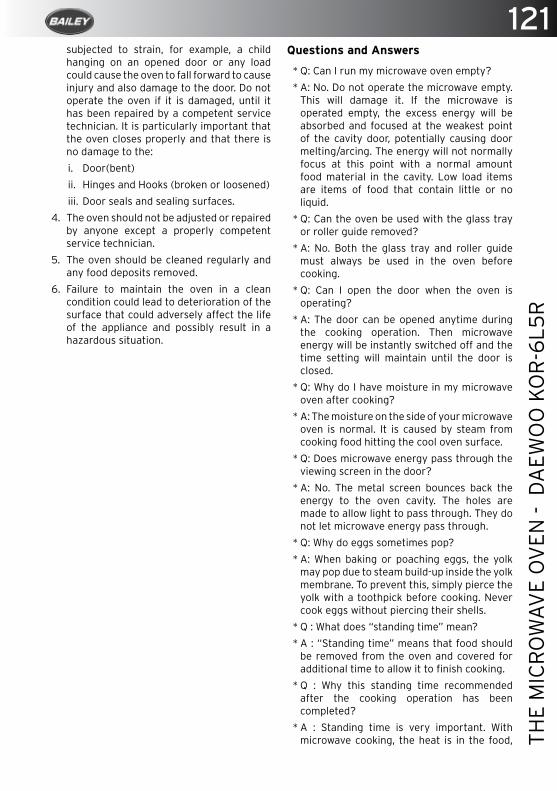
121
THE
MIC
RO
WAV
E O
VEN
- D
AEW
OO
KO
R-6
L5R
subjected to strain, for example, a child hanging on an opened door or any load could cause the oven to fall forward to cause injury and also damage to the door. Do not operate the oven if it is damaged, until it has been repaired by a competent service technician. It is particularly important that the oven closes properly and that there is no damage to the:
i. Door(bent)
ii. Hinges and Hooks (broken or loosened)
iii. Door seals and sealing surfaces.
4. The oven should not be adjusted or repaired by anyone except a properly competent service technician.
5. The oven should be cleaned regularly and any food deposits removed.
6. Failure to maintain the oven in a clean condition could lead to deterioration of the surface that could adversely affect the life of the appliance and possibly result in a hazardous situation.
Questions and Answers
* Q: Can I run my microwave oven empty?
* A: No. Do not operate the microwave empty. This will damage it. If the microwave is operated empty, the excess energy will be absorbed and focused at the weakest point of the cavity door, potentially causing door melting/arcing. The energy will not normally focus at this point with a normal amount food material in the cavity. Low load items are items of food that contain little or no liquid.
* Q: Can the oven be used with the glass tray or roller guide removed?
* A: No. Both the glass tray and roller guide must always be used in the oven before cooking.
* Q: Can I open the door when the oven is operating?
* A: The door can be opened anytime during the cooking operation. Then microwave energy will be instantly switched off and the time setting will maintain until the door is closed.
* Q: Why do I have moisture in my microwave oven after cooking?
* A: The moisture on the side of your microwave oven is normal. It is caused by steam from cooking food hitting the cool oven surface.
* Q: Does microwave energy pass through the viewing screen in the door?
* A: No. The metal screen bounces back the energy to the oven cavity. The holes are made to allow light to pass through. They do not let microwave energy pass through.
* Q: Why do eggs sometimes pop?
* A: When baking or poaching eggs, the yolk may pop due to steam build-up inside the yolk membrane. To prevent this, simply pierce the yolk with a toothpick before cooking. Never cook eggs without piercing their shells.
* Q : What does “standing time” mean?
* A : “Standing time” means that food should be removed from the oven and covered for additional time to allow it to finish cooking.
* Q : Why this standing time recommended after the cooking operation has been completed?
* A : Standing time is very important. With microwave cooking, the heat is in the food,
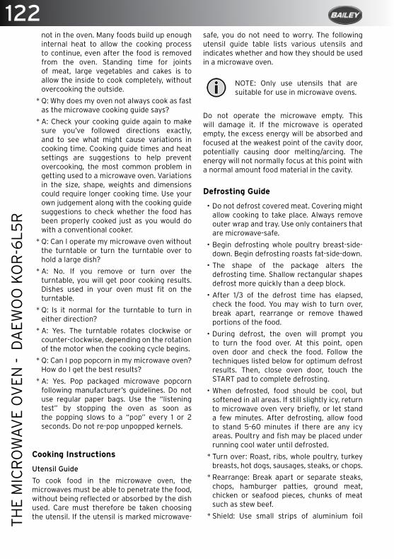
122TH
E M
ICR
OW
AVE
OV
EN -
DA
EWO
O K
OR
-6L5
R
not in the oven. Many foods build up enough internal heat to allow the cooking process to continue, even after the food is removed from the oven. Standing time for joints of meat, large vegetables and cakes is to allow the inside to cook completely, without overcooking the outside.
* Q: Why does my oven not always cook as fast as the microwave cooking guide says?
* A: Check your cooking guide again to make sure you’ve followed directions exactly, and to see what might cause variations in cooking time. Cooking guide times and heat settings are suggestions to help prevent overcooking, the most common problem in getting used to a microwave oven. Variations in the size, shape, weights and dimensions could require longer cooking time. Use your own judgement along with the cooking guide suggestions to check whether the food has been properly cooked just as you would do with a conventional cooker.
* Q: Can I operate my microwave oven without the turntable or turn the turntable over to hold a large dish?
* A: No. If you remove or turn over the turntable, you will get poor cooking results. Dishes used in your oven must fit on the turntable.
* Q: Is it normal for the turntable to turn in either direction?
* A: Yes. The turntable rotates clockwise or counter-clockwise, depending on the rotation of the motor when the cooking cycle begins.
* Q: Can I pop popcorn in my microwave oven? How do I get the best results?
* A: Yes. Pop packaged microwave popcorn following manufacturer’s guidelines. Do not use regular paper bags. Use the “listening test” by stopping the oven as soon as the popping slows to a “pop” every 1 or 2 seconds. Do not re-pop unpopped kernels.
Cooking Instructions
Utensil Guide
To cook food in the microwave oven, the microwaves must be able to penetrate the food, without being reflected or absorbed by the dish used. Care must therefore be taken choosing the utensil. If the utensil is marked microwave-
safe, you do not need to worry. The following utensil guide table lists various utensils and indicates whether and how they should be used in a microwave oven.
NOTE: Only use utensils that are suitable for use in microwave ovens.
Do not operate the microwave empty. This will damage it. If the microwave is operated empty, the excess energy will be absorbed and focused at the weakest point of the cavity door, potentially causing door melting/arcing. The energy will not normally focus at this point with a normal amount food material in the cavity.
Defrosting Guide
• Do not defrost covered meat. Covering might allow cooking to take place. Always remove outer wrap and tray. Use only containers that are microwave-safe.
• Begin defrosting whole poultry breast-side-down. Begin defrosting roasts fat-side-down.
• The shape of the package alters the defrosting time. Shallow rectangular shapes defrost more quickly than a deep block.
• After 1/3 of the defrost time has elapsed, check the food. You may wish to turn over, break apart, rearrange or remove thawed portions of the food.
• During defrost, the oven will prompt you to turn the food over. At this point, open oven door and check the food. Follow the techniques listed below for optimum defrost results. Then, close oven door, touch the START pad to complete defrosting.
• When defrosted, food should be cool, but softened in all areas. If still slightly icy, return to microwave oven very briefly, or let stand a few minutes. After defrosting, allow food to stand 5-60 minutes if there are any icy areas. Poultry and fish may be placed under running cool water until defrosted.
* Turn over: Roast, ribs, whole poultry, turkey breasts, hot dogs, sausages, steaks, or chops.
* Rearrange: Break apart or separate steaks, chops, hamburger patties, ground meat, chicken or seafood pieces, chunks of meat such as stew beef.
* Shield: Use small strips of aluminium foil
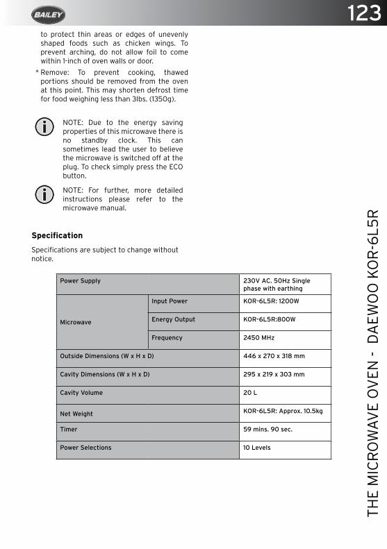
123
THE
MIC
RO
WAV
E O
VEN
- D
AEW
OO
KO
R-6
L5R
to protect thin areas or edges of unevenly shaped foods such as chicken wings. To prevent arching, do not allow foil to come within 1-inch of oven walls or door.
* Remove: To prevent cooking, thawed portions should be removed from the oven at this point. This may shorten defrost time for food weighing less than 3lbs. (1350g).
NOTE: Due to the energy saving properties of this microwave there is no standby clock. This can sometimes lead the user to believe the microwave is switched off at the plug. To check simply press the ECO button.
NOTE: For further, more detailed instructions please refer to the microwave manual.
Specification
Specifications are subject to change without notice.
Power Supply 230V AC. 50Hz Single phase with earthing
Microwave
Input Power KOR-6L5R: 1200W
Energy Output KOR-6L5R:800W
Frequency 2450 MHz
Outside Dimensions (W x H x D) 446 x 270 x 318 mm
Cavity Dimensions (W x H x D) 295 x 219 x 303 mm
Cavity Volume 20 L
Net Weight KOR-6L5R: Approx. 10.5kg
Timer 59 mins. 90 sec.
Power Selections 10 Levels
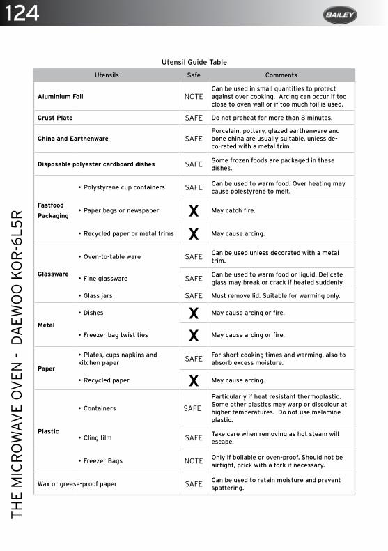
124TH
E M
ICR
OW
AVE
OV
EN -
DA
EWO
O K
OR
-6L5
R
Utensil Guide Table
Utensils Safe Comments
Aluminium Foil NOTECan be used in small quantities to protect against over cooking. Arcing can occur if too close to oven wall or if too much foil is used.
Crust Plate SAFE Do not preheat for more than 8 minutes.
China and Earthenware SAFEPorcelain, pottery, glazed earthenware and bone china are usually suitable, unless de-co-rated with a metal trim.
Disposable polyester cardboard dishes SAFE Some frozen foods are packaged in these dishes.
Fastfood
Packaging
• Polystyrene cup containers SAFE Can be used to warm food. Over heating may cause polestyrene to melt.
• Paper bags or newspaper X May catch fire.
• Recycled paper or metal trims X May cause arcing.
Glassware
• Oven-to-table ware SAFE Can be used unless decorated with a metal trim.
• Fine glassware SAFE Can be used to warm food or liquid. Delicate glass may break or crack if heated suddenly.
• Glass jars SAFE Must remove lid. Suitable for warming only.
Metal
• Dishes X May cause arcing or fire.
• Freezer bag twist ties X May cause arcing or fire.
Paper
• Plates, cups napkins and kitchen paper SAFE For short cooking times and warming, also to
absorb excess moisture.
• Recycled paper X May cause arcing.
Plastic
• Containers SAFE
Particularly if heat resistant thermoplastic. Some other plastics may warp or discolour at higher temperatures. Do not use melamine plastic.
• Cling film SAFE Take care when removing as hot steam will escape.
• Freezer Bags NOTE Only if boilable or oven-proof. Should not be airtight, prick with a fork if necessary.
Wax or grease-proof paper SAFE Can be used to retain moisture and prevent spattering.
125
THE
DO
MET
IC R
EFR
IGER
ATO
R
The Dometic Refrigerator
Modes Of Operation ....................................................................................................... 126
Explanation Of Operating Controls ............................................................................ 126
Starting The Refrigerator Using Gas ..........................................................................127
Door Locking.....................................................................................................................127
Positioning Storage Racks ............................................................................................ 128
Removeable Freezer Compartment ........................................................................... 128
Defrosting ......................................................................................................................... 128
Shutting Off The Refrigerator ..................................................................................... 129
Exchange Of The Ignitors Battery .............................................................................. 129
Winter Operation ............................................................................................................ 129
Cleaning and Maintenance ........................................................................................... 130
Safety Instructions .......................................................................................................... 131
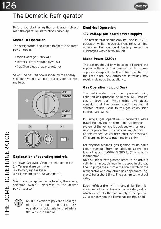
126TH
E D
OM
ETIC
REF
RIG
ERA
TOR
The Dometic Refrigerator
Before you start using the refrigerator, please read the operating instructions carefully.
Modes Of Operation
The refrigerator is equipped to operate on three power modes:
> Mains voltage (230V AC)
> Direct-current voltage (12V DC)
> Gas (liquid gas propane/butane)
Select the desired power mode by the energyselector switch 1 (see fig 1) (battery igniter type models).
Explanation of operating controls
1 = Power On switch/ Energy selector switch2 = Temperature controller3 = Battery igniter (gas)4 = Flame indicator (galvanometer)
Switch on the appliance by turning the energy selection switch 1 clockwise to the desired power source.
NOTE: In order to prevent discharge of the on-board battery, 12V operation should only be used while the vehicle is running.
Electrical Operation
12v-voltage (on-board power supply)
The refrigerator should only be used in 12V DC operation while the vehicle’s engine is running, otherwise the on-board battery would be discharged within a few hours!
Mains Power (230v)
This option should only be selected where the supply voltage of the connection for power supply corresponds to the value specified on the data plate. Any difference in values may result in damage the appliance.
Gas Operation (Liquid Gas)
The refrigerator must be operated using liquefied gas (propane or butane NOT natural gas or town gas). When using LPG please consider that the burner needs cleaning at shorter intervals due to the gas combustion method (annually).
In Europe, gas operation is permitted while travelling only on the condition that the gassystem of the vehicle is equipped with a hoserupture protection. The national regulationsof the respective country must be observed. (This applies to Autograph models only).
For physical reasons, gas ignition faults could occur starting from an altitude above sea level of approx. 1,000m/3,280 ft. (This is not a malfunction!)On the initial refrigerator start-up or after a cylinder change, air may be trapped in the gas line. To purge the air from the line, switch on the refrigerator and any other gas appliances (e.g. stove) for a short time. The gas ignites without delay.
Each refrigerator with manual ignition is equipped with an automatic flame safety valve which interrupts the gas supply after approx 30 seconds when the flame has extinguished.
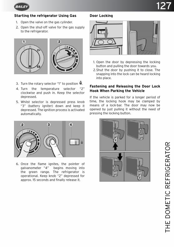
127
THE
DO
MET
IC R
EFR
IGER
ATO
R
Starting the refrigerator Using Gas
1. Open the valve on the gas cylinder.
2. Open the shut-off valve for the gas supply to the refrigerator.
3. Turn the rotary selector “1” to position .
4. Turn the temperature selector “2” clockwise and push in. Keep the selector depressed.
5. Whilst selector is depressed press knob “3” (battery igniter) down and keep it depressed. The ignition process is activated automatically.
6. Once the flame ignites, the pointer of galvanometer “4” begins moving into the green range. The refrigerator is operational. Keep knob “2” depressed for approx. 15 seconds and finally release it.
Door Locking
1. Open the door by depressing the locking button and pulling the door towards you.
2. Shut the door by pushing it to close. The snapping into the lock can be heard locking into place.
Fastening and Releasing the Door Lock Hook When Parking the Vehicle
If the vehicle is parked for a longer period of time, the locking hook may be clamped by means of a lock-bar. The door may now be opened by just pulling it without the need of pressing the locking button.
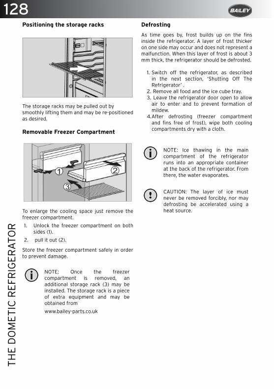
128TH
E D
OM
ETIC
REF
RIG
ERA
TOR
Positioning the storage racks
The storage racks may be pulled out bysmoothly lifting them and may be re-positioned as desired.
Removable Freezer Compartment
To enlarge the cooling space just remove the freezer compartment.
1. Unlock the freezer compartment on both sides (1).
2. pull it out (2).
Store the freezer compartment safely in order to prevent damage.
NOTE: Once the freezer compartment is removed, an additional storage rack (3) may be installed. The storage rack is a piece of extra equipment and may be obtained from
www.bailey-parts.co.uk
Defrosting
As time goes by, frost builds up on the fins inside the refrigerator. A layer of frost thicker on one side may occur and does not represent a malfunction. When this layer of frost is about 3 mm thick, the refrigerator should be defrosted.
1. Switch off the refrigerator, as described in the next section, ‘Shutting Off The Refrigerator’ .
2. Remove all food and the ice cube tray.3. Leave the refrigerator door open to allow
air to enter and to prevent formation of mildew.
4. After defrosting (freezer compartment and fins free of frost), wipe both cooling compartments dry with a cloth.
NOTE: Ice thawing in the main compartment of the refrigerator runs into an appropriate container at the back of the refrigerator. From there, the water evaporates.
CAUTION: The layer of ice must never be removed forcibly, nor may defrosting be accelerated using a heat source.

129
THE
DO
MET
IC R
EFR
IGER
ATO
R
Shutting Off The Refrigerator
1. Set energy selector switch to position OFF; the appliance is switched off.
2. Release the locking mechanism of the door lock by pushing it and shift it to the front. If the door is shut in this position, a small gap is nevertheless kept open to prevent formation of mildew; see fig. 10.
3. If the refrigerator is to be taken out of service for an extended period of time, close the on-board shut-off valve and the door.
Exchange Of The Igniter’s Battery
Unlock the battery by depressing and turningthe button ‘C’ approx. 90° clockwise. Remove cap and exchange battery (1.5V AAA/R3/Micro). Observe correct polarity.
Winter Operation
In winter, check that the ventilation grilles andthe exhaust duct system (1) have not been blocked by snow, leaves, etc.
When the outside temperature falls below +8°c, a winter cover should be fitted. This protects the unit from excessively cold air which could have adverse effects on the performance of the unit. You should also attach the winter cover if the vehicle is taken out of service for a longer period of time or while it is being cleaned from the outside.
The cover can be purchased from a www.bailey-parts.co.uk Installation may only be carried out by authorised personnel. We recommend contacting your Dometic Service Centre.EN 1949 stipulates that the appliance’s, gas equipment and its associated fume system must be inspected after installation and a certificate issued.
When using the fridge for extended periods on gas operation Dometic recommend a seasonal service is carried out by authorised personnel. It is the user’s responsibility to arrange for inspections after purchase.It is recommended that the gas burner be inspected and cleaned as necessary at least once a year.

130TH
E D
OM
ETIC
REF
RIG
ERA
TOR
Cleaning
Before starting up the refrigerator, it is recommended to clean inside and repeat this at regular intervals. Use a soft cloth and lukewarm water with a mild detergent. Then wipe out the appliance with clean water and dry thoroughly.
NOTE: To avoid deterioration of materials, DO NOT use soap or hard, abrasive or soda-based cleaning agents. Do not allow the door seal to come into contact with oil or grease.
Maintenance
In compliance with the applicable regulations, please note that the gas unit and the connected ventilation ducts must be checked by authorised technical personnel after first use and after every other year for compliance with the European Standard EN 1949. A test certificate has to be issued. It is the user’s responsibility to arrange this test.
The gas burner must be inspected and cleaned as necessary at least once a year.When using liquefied petroleum gas (tank or refill cylinders) the maintenance interval is reduced to half-yearly or quarterly. Keep the evidence of maintenance work carried out on your refrigerator.
Work on gas and electrical equipment shall be carried out by qualified personnel only.
Safety Instructions
This refrigerator is designed for installation in motorhomes. The appliance has been type approval tested for this application in accordance with the EC Gas Directive.
The refrigerator is to be used solely for storingfoodstuffs.
WARNING: The refrigerator is not suitable for the proper storage of medication. Please observe in addition the instructions in the medication package inserts.
User’s responsibility
Anyone operating the refrigerator must be familiar with the safe handling and understand the advice in these operating instructions. Children may only operate the appliance, if they have been made aware of how to operate the refrigerator safely and the dangers attending incorrect operation.
Disposal
WARINING: When disposing of the refrigerator, detach all refrigerator doors and leave the storage racks in the refrigerator. In this way, inadvertent entrapment and suffocation is prevented.
Working upon and checking the refrigerator
WARNING: Work on gas equipment, exhaust system and electrical facilities must be carried out by authorised personnel only. Substantial damage to property and/or injury to persons can arise through unprofessional procedures.
WARNING: Never use an unshielded flame to check gas bearing parts and pipes for leakage.
WARNING: Never open the absorber cooling unit! It is under high pressure.
Information on coolant
Ammonia is used as a coolant. This is a natural compound also used in household cleaning agents (1 litre of Salmiak cleaner contains up to 200g of ammonia - about twice as much as is used in the refrigerator). Sodium chromate is used for corrosion protection (1.8% by weight of the solvent). In the event of leakage (easily identifiable from the strong odour), proceed as follows:
• Switch off the appliance.

131
THE
DO
MET
IC R
EFR
IGER
ATO
R
• Air the room thoroughly.• Inform authorised customer services.
Safety When Operating the refrigerator with gas
It is imperative that the operating pressurecorresponds to the data specified on therating plate of the appliance. Compare theoperating pressure of the rating plate with thedata specified on the pressure reducing valveof the liquid gas cylinder.
WARNING: Operating the appliance with gas is not permitted at petrol stations on ferry boats while transporting the caravan/motorhome by a transporter or breakdown vehicle.
Safety instructions when storing foodstuffs
No refrigerator of any kind can improve the quality of the food; refrigerators can only maintain the food’s quality for a short duration as from the time of storing it.
Please observe the following particular conditions for storing food in a refrigerator that is built into a vehicle:
Under the below conditions the refrigerator cannot guarantee reaching the temperature needed for perishables. Perishables include all products with a stipulated use-by date and a minimum storage temperature of +4°C or less, especially for meat, poultry, fish, sausages, pre-packed foods.
• A change in the climatic conditions such astemperature fluctuations.
• High temperatures inside the vehicle whenit is closed and parked in direct sunlight(temperatures are possible up to 50°C).
• Use of the refrigerator during travel with thepower supply of 12V DC.
• A refrigerator built in behind a window andexposed to direct sunlight.
• Storing the products too soon, i.e. shortlyafter starting up the appliance for use.
• Pack raw and cooked foods separately (e.g. in containers, aluminium foil, etc.).
• Only remove the outside packaging of single
packs if all the necessary information, e.g. the use-by date, can also be read on the single packs.
• Do not leave cooled goods outside therefrigerator for too long.
• Place the foods with the next use-by date atthe front, accordingly.
• Pack away any left-over food and eat at thefirst opportunity.
• Wash your hands before and after handlingany food.
• Regularly clean the inside of the refrigerator.
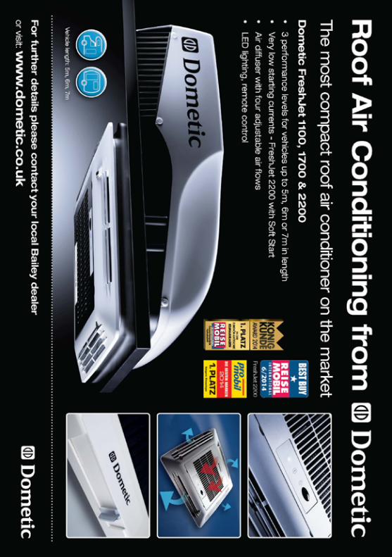
133
SUR
FAC
E C
AR
E
Surface Care
Mirrors ............................................................................................................................... 134
Bathroom Shower Tap ................................................................................................... 134
T/C Sink ............................................................................................................................. 134
Ecocamel Shower Head ................................................................................................. 135
FENIX Nanotech Work Surfaces .................................................................................. 136
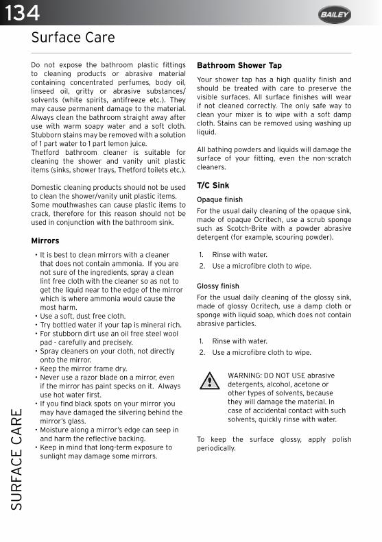
134SU
RFA
CE
CA
RE
Surface Care
Do not expose the bathroom plastic fittings to cleaning products or abrasive material containing concentrated perfumes, body oil, linseed oil, gritty or abrasive substances/ solvents (white spirits, antifreeze etc.). They may cause permanent damage to the material. Always clean the bathroom straight away after use with warm soapy water and a soft cloth. Stubborn stains may be removed with a solution of 1 part water to 1 part lemon juice.Thetford bathroom cleaner is suitable for cleaning the shower and vanity unit plastic items (sinks, shower trays, Thetford toilets etc.).
Domestic cleaning products should not be used to clean the shower/vanity unit plastic items.Some mouthwashes can cause plastic items to crack, therefore for this reason should not be used in conjunction with the bathroom sink.
Mirrors
• It is best to clean mirrors with a cleaner that does not contain ammonia. If you are not sure of the ingredients, spray a clean lint free cloth with the cleaner so as not to get the liquid near to the edge of the mirror which is where ammonia would cause the most harm.
• Use a soft, dust free cloth.• Try bottled water if your tap is mineral rich.• For stubborn dirt use an oil free steel wool
pad - carefully and precisely.• Spray cleaners on your cloth, not directly
onto the mirror.• Keep the mirror frame dry.• Never use a razor blade on a mirror, even
if the mirror has paint specks on it. Always use hot water first.
• If you find black spots on your mirror you may have damaged the silvering behind the mirror’s glass.
• Moisture along a mirror’s edge can seep in and harm the reflective backing.
• Keep in mind that long-term exposure to sunlight may damage some mirrors.
Bathroom Shower Tap
Your shower tap has a high quality finish and should be treated with care to preserve the visible surfaces. All surface finishes will wear if not cleaned correctly. The only safe way to clean your mixer is to wipe with a soft damp cloth. Stains can be removed using washing up liquid.
All bathing powders and liquids will damage the surface of your fitting, even the non-scratch cleaners.
T/C Sink
Opaque finish
For the usual daily cleaning of the opaque sink, made of opaque Ocritech, use a scrub sponge such as Scotch-Brite with a powder abrasive detergent (for example, scouring powder). 1. Rinse with water.
2. Use a microfibre cloth to wipe.
Glossy finish
For the usual daily cleaning of the glossy sink, made of glossy Ocritech, use a damp cloth or sponge with liquid soap, which does not contain abrasive particles. 1. Rinse with water.
2. Use a microfibre cloth to wipe.
WARNING: DO NOT USE abrasive detergents, alcohol, acetone or other types of solvents, because they will damage the material. In case of accidental contact with such solvents, quickly rinse with water.
To keep the surface glossy, apply polish periodically.

135
SUR
FAC
E C
AR
E
Ecocamel Shower Head
Your motorhome is fitted with an Ecocamel shower head;
> It saves water, energy and money.
> It has a wipe clean head to prevent the build-up of lime scale.
> Uses a maximum of 8 litres a minute.
After showering, when the shower is turned off, your Ecocamel shower head simply drains off any excess water through the air intake.Clean your Ecocamel shower head with a damp cloth. Do not use any abrasive or chemical cleaners. Should any scale build up on your shower head’s spray plate, de-scale by rubbing the nozzles with your thumb.
The Ecocamel shower head will fit all motorhome showers and is available from the Bailey Parts department: [email protected]
Cleaning The Face Plate

136SU
RFA
CE
CA
RE
the FENIX NTM surface. Any streaks can still be removed by rinsing with hot water and drying.
• Avoid furniture polishes and wax based cleaners in general, because they tend to form a sticky layer on the dense FENIX NTM surface, to which the dirt adheres.
FENIX Nanotech Work Surfaces
The surface of FENIX NTM involves the use of nanotechnology and is obtained through next generation resins developed by Arpa Industriale. Thanks to its technology, FENIX NTM features advance properties. Besides the main ones, such as an extremely matt, soft touch, and anti-fingerprint surface, and the thermal healing of microscratches, this innovative material stands out for specific properties which facilitate normal cleaning and do not require particular maintenance. In fact, it is extremely easy to clean and is resistant to mold, it has enhanced anti-bacterial properties, it is resistant to rub, scratches and abrasion, as well as to acid solvents and household reagents.
Ordinary maintenance
FENIX NTM surface should be cleaned regularly but does not require any special maintenance, just a damp cloth with warm water or milddetergents. Almost all normal household cleaning products or disinfectants are perfectly well tolerated. It is suggested to use a melaminefoam sponge - also known as magic sponge - for the normal cleaning and maintenance of the surface.
Extraordinary maintenance
In case of dirt which cannot be cleaned with normal household detergents, due to the irregular topography and closed surface of FENIX NTM, the use of non-aggressive aromatic solvents (acetone) is suggested. In case of micro scratches, please refer to the specific surfacethermal healing instructions.
General precautions
For best results in cleaning FENIX NTM, it is important to remember certain precautions:
• Although very durable, the surface of FENIX NTM must still never be treated with products containing abrasive substances, abrasive sponges or unsuitable products, such as sandpaper or steel wool;
• Products with a high acid or very alkaline content should be avoided because they can stain the surface;
• When using solvents, the cloth used must be perfectly clean so as not to leave marks on

137
SUR
FAC
E C
AR
E
Thermal Healing Of Microscratches
Maintenance Instructions
Melamine Foam Sponge
139
THE
THET
FOR
D C
262
TOIL
ET
The Thetford C262 Toilet
Introduction ..................................................................................................................... 140
Parts .................................................................................................................................. 140
Preparing Your Toilet ...................................................................................................... 141
Cleaning And Maintenance ........................................................................................... 142
Cleaning The Toilet Bowl ............................................................................................... 142
Cleaning the Waste Holding Tank ............................................................................... 142
Winter Operation ............................................................................................................ 143
Storage .............................................................................................................................. 143
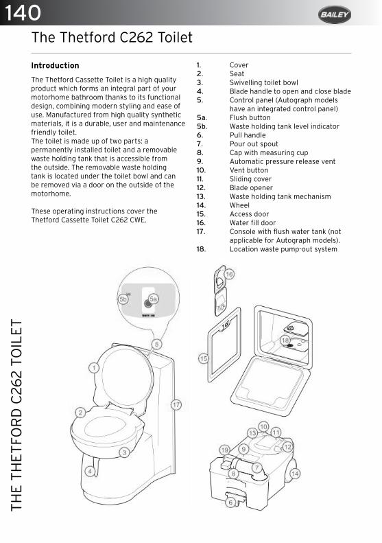
140TH
E TH
ETFO
RD
C26
2 TO
ILET
The Thetford C262 Toilet
Introduction
The Thetford Cassette Toilet is a high quality product which forms an integral part of your motorhome bathroom thanks to its functional design, combining modern styling and ease of use. Manufactured from high quality synthetic materials, it is a durable, user and maintenance friendly toilet.The toilet is made up of two parts: a permanently installed toilet and a removable waste holding tank that is accessible from the outside. The removable waste holding tank is located under the toilet bowl and can be removed via a door on the outside of the motorhome.
These operating instructions cover the Thetford Cassette Toilet C262 CWE.
1. Cover2. Seat 3. Swivelling toilet bowl4. Blade handle to open and close blade5. Control panel (Autograph models have an integrated control panel)5a. Flush button5b. Waste holding tank level indicator6. Pull handle7. Pour out spout8. Cap with measuring cup9. Automatic pressure release vent10. Vent button11. Sliding cover12. Blade opener13. Waste holding tank mechanism14. Wheel 15. Access door16. Water fill door17. Console with flush water tank (not applicable for Autograph models).18. Location waste pump-out system
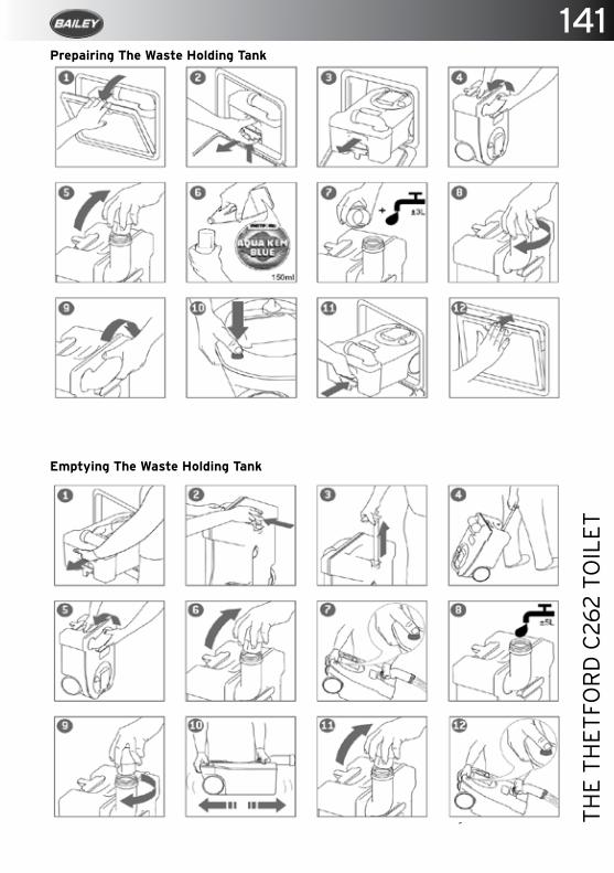
141
THE
THET
FOR
D C
262
TOIL
ET
Prepairing The Waste Holding Tank
Emptying The Waste Holding Tank
Using The Toilet
1. Turn the bowl to the desired position with the lid closed and using both hands.
142TH
E TH
ETFO
RD
C26
2 TO
ILET
To activate the control panel, press the flush-button once. The control panel display will stay activated for approximately 5 minutes. Run some water into the bowl by pressing the flush button again briefly.The toilet should be used with the blade open. To open the blade, slide the blade handle under the toilet bowl sideways. After use, open the blade (if still closed) and flush the toilet by pressing the flush button for several seconds (if necessary re-activate the control panel). Close the blade after use. If your toilet has its own flush-water tank, please make sure that you do not travel with a flush-water tank that is too full and with water in the toilet bowl. Failure to adhere to this notice may result in water damage to your motorhome.The waste holding tank requires emptying when the red light (LED) on the toilet control display lights up. At that point the waste holding tank only has capacity for two more litres which is no more than two to three further uses.
Cleaning And Maintenance
The toilet should be cleaned and maintained regularly, depending on the amount of use. To clean the Thetford toilet, we advise using water and Thetford Bathroom Cleaner. Never use bleach, vinegar or other powerful household cleaners that contain these substances. These may cause permanent damage to the seals and other toilet components.
Cleaning The Toilet Bowl
1. Squirt Thetford Bathroom Cleaner into the toilet bowl.
2. Flush the toilet bowl with water and wipe down the rest of the toilet with a damp cloth.
3. To clean the seat and lid, remove by lifting the seat and lid assembly and pulling the round pins (inside the assembly) outwards from the pin holes. After cleaning, replace the seat and lid by positioning the round pins in front of the pin holes and push the lid and seat downwards.
4. To keep your flush water fresh and to prevent deposits forming in your toilet bowl, add a correct dosage of Aqua Rinse in your flush-water tank.
5. Dry with a soft dry cloth after cleaning.
Cleaning the Waste Holding Tank
To keep your waste holding tank fresh and clean, Thetford has developed a number of different toilet fluids. Thetford toilet fluids suppress smells, reduce formation of gas, promote breakdown of toilet waste and increase the life span of a mobile toilet. We advise a thorough cleaning of the waste holding tank once each season.
Next to using Thetford’s Cassette Tank Cleaner, which is the powerful cleaning agent for the periodical cleaning of the waste holding tank of your toilet we suggest the following:
1. Remove the removable mechanism from the waste holding tank by turning it anti-clockwise and rinse it under a tap.
2. Remove the cover plate from the automatic pressure release vent by prising it up using a small screwdriver. Use one hand to push the automatic pressure release vent open while holding the float of the automatic pressure release vent on the inside of the tank with the other hand. Push the float upwards, turn it 180° and remove it from below. Remove the rubber seal underneath the float. Rinse the float and rubber seal under a tap. Replace the rubber seal and float for the automatic pressure release vent using the same method in reverse.
3. The rubber seals in the toilet (the lip seal, the mechanism seal, the automatic pressure release vent seal and the cap seal) should be regularly cleaned with water and treated with Thetford High Grade Seal Lubricant. This will ensure that the seals remain flexible and in good condition. If the toilet is not to be used for any length of time, it is important to treat the seals with Thetford High Grade Seal Lubricant after cleaning.
4. Never use Vaseline or any vegetable oil except olive oil. These may cause leakage or malfunction. The lip seal is a part of the toilet that is subject to wear. Depending upon the extent and manner of use, the seals will become less effective and will need replacing periodically.
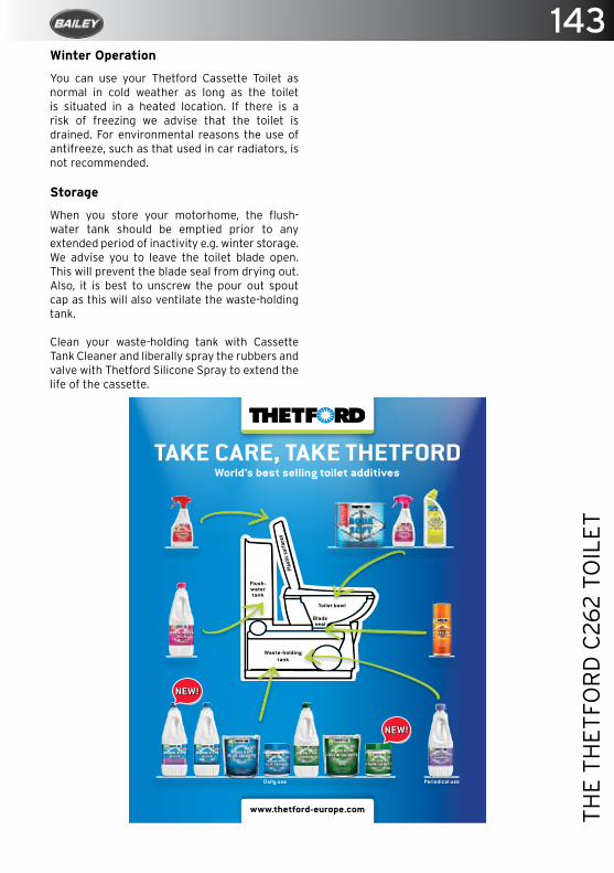
143
THE
THET
FOR
D C
262
TOIL
ET
Winter Operation
You can use your Thetford Cassette Toilet as normal in cold weather as long as the toilet is situated in a heated location. If there is a risk of freezing we advise that the toilet is drained. For environmental reasons the use of antifreeze, such as that used in car radiators, is not recommended.
Storage
When you store your motorhome, the flush-water tank should be emptied prior to any extended period of inactivity e.g. winter storage. We advise you to leave the toilet blade open. This will prevent the blade seal from drying out. Also, it is best to unscrew the pour out spout cap as this will also ventilate the waste-holding tank.
Clean your waste-holding tank with Cassette Tank Cleaner and liberally spray the rubbers and valve with Thetford Silicone Spray to extend the life of the cassette.
Thetford_Advertentie_EN_A5_Baileys_260716.indd 1 26-07-16 16:04
144FI
TTED
FU
RN
ITU
RE
CO
NFI
GU
RA
TIO
NS
Fitted Furniture Configurations
79-4/79-4T Bed Configuration .................................................................................... 145
79-4/79-4T L Shaped Lounge Configuration ........................................................... 146
79-4 Rear Bed Extension .............................................................................................. 146
79-6 Front Bed Configuration ...................................................................................... 147
79-6 Rear Bed Configuration ....................................................................................... 148
75-2 Front Bed Configuration ...................................................................................... 149
75-4 Front Bed Configuration ...................................................................................... 150
Autograph Drop Down Bed ............................................................................................ 151
Advance Electric Drop-down Bed ............................................................................... 152
Safety Protection ............................................................................................................ 152
Emergencies .................................................................................................................... 152
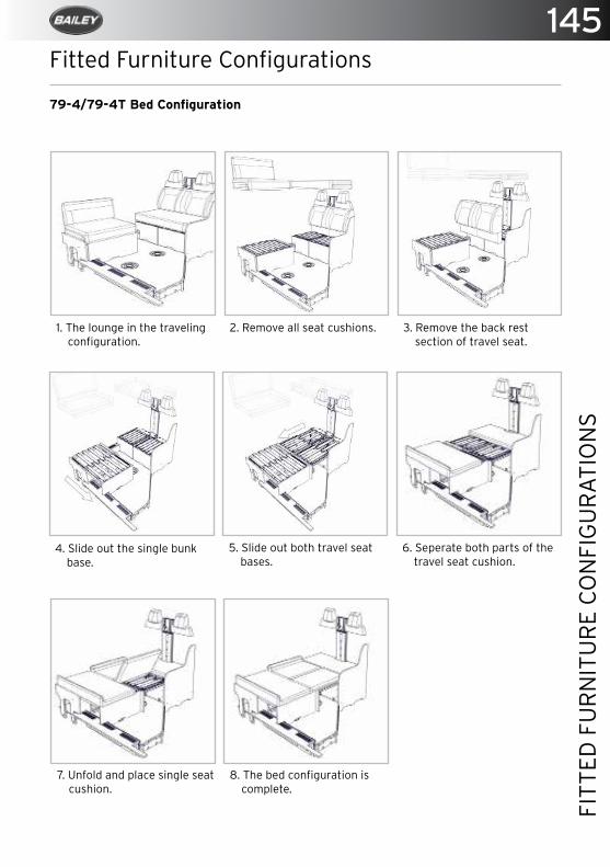
145
FITT
ED F
UR
NIT
UR
E C
ON
FIG
UR
ATI
ON
S
Fitted Furniture Configurations
1. The lounge in the traveling configuration.
2. Remove all seat cushions. 3. Remove the back rest section of travel seat.
4. Slide out the single bunk base.
5. Slide out both travel seat bases.
6. Seperate both parts of the travel seat cushion.
7. Unfold and place single seat cushion.
8. The bed configuration is complete.
79-4/79-4T Bed Configuration

146FI
TTED
FU
RN
ITU
RE
CO
NFI
GU
RA
TIO
NS
79-4/79-4T L Shaped Lounge Configuration
1. The lounge in the travel configuration.
2. Slide out the offside travel seat base.
3. Position the infill cushion to complete the lounge seat configuration.
79-4 Rear Bed Extension
1. The bed is shown in the seated position.
2. Lift up the handle and pull the bed out.
3. The bed is extended.Reverse operation to close.
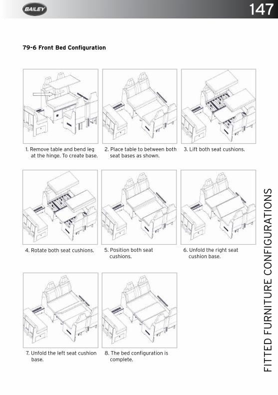
147
FITT
ED F
UR
NIT
UR
E C
ON
FIG
UR
ATI
ON
S
1. Remove table and bend leg at the hinge. To create base.
2. Place table to between both seat bases as shown.
3. Lift both seat cushions.
4. Rotate both seat cushions. 5. Position both seat cushions.
6. Unfold the right seat cushion base.
7. Unfold the left seat cushion base.
8. The bed configuration is complete.
79-6 Front Bed Configuration
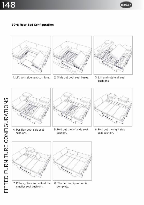
148FI
TTED
FU
RN
ITU
RE
CO
NFI
GU
RA
TIO
NS
1. Lift both side seat cushions. 2. Slide out both seat bases. 3. Lift and rotate all seat cushions.
4. Position both side seat cushions.
5. Fold out the left side seat cushion.
6. Fold out the right side seat cushion.
7. Rotate, place and unfold the smaller seat cushions.
8. The bed configuration is complete.
79-6 Rear Bed Configuration
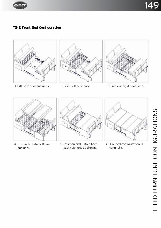
149
FITT
ED F
UR
NIT
UR
E C
ON
FIG
UR
ATI
ON
S
1. Lift both seat cushions. 2. Slide left seat base. 3. Slide out right seat base.
4. Lift and rotate both seat cushions.
5. Position and unfold both seat cushions as shown.
6. The bed configuration is complete.
75-2 Front Bed Configuration
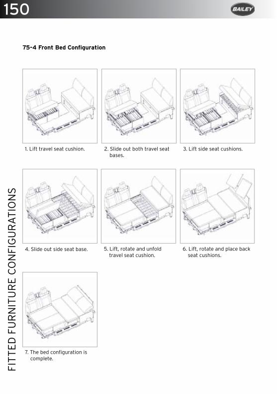
150FI
TTED
FU
RN
ITU
RE
CO
NFI
GU
RA
TIO
NS
1. Lift travel seat cushion. 2. Slide out both travel seat bases.
3. Lift side seat cushions.
4. Slide out side seat base. 5. Lift, rotate and unfold travel seat cushion.
6. Lift, rotate and place back seat cushions.
7. The bed configuration is complete.
75-4 Front Bed Configuration
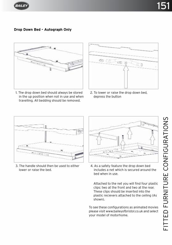
151
FITT
ED F
UR
NIT
UR
E C
ON
FIG
UR
ATI
ON
S
1. The drop down bed should always be stored in the up position when not in use and when travelling. All bedding should be removed.
2. To lower or raise the drop down bed, depress the button
3. The handle should then be used to either lower or raise the bed.
Drop Down Bed - Autograph Only
4. As a safety feature the drop down bed includes a net which is secured around the bed when in use.
Attached to the net you will find four plastic clips: two at the front and two at the rear. These clips should be inserted into the plastic recievers attached to the ceiling (As shown).
To see these configurations as animated movies please visit www.baileyofbristol.co.uk and select your model of motorhome.
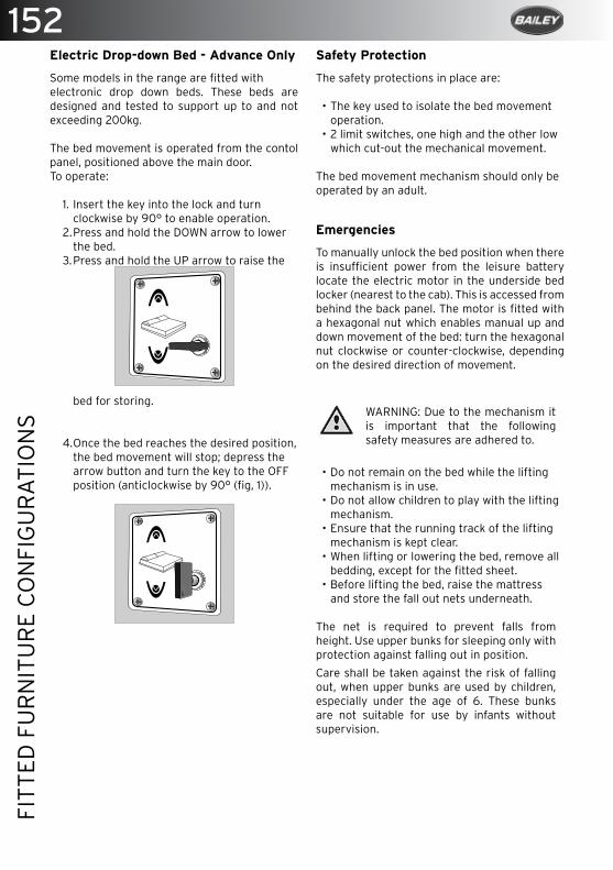
152FI
TTED
FU
RN
ITU
RE
CO
NFI
GU
RA
TIO
NS
Electric Drop-down Bed - Advance Only
Some models in the range are fitted withelectronic drop down beds. These beds are designed and tested to support up to and not exceeding 200kg.
The bed movement is operated from the contol panel, positioned above the main door. To operate:
1. Insert the key into the lock and turn clockwise by 90° to enable operation.
2. Press and hold the DOWN arrow to lower the bed.
3. Press and hold the UP arrow to raise the
bed for storing.
4. Once the bed reaches the desired position, the bed movement will stop; depress the arrow button and turn the key to the OFF position (anticlockwise by 90° (fig, 1)).
Safety Protection
The safety protections in place are:
• The key used to isolate the bed movement operation.
• 2 limit switches, one high and the other low which cut-out the mechanical movement.
The bed movement mechanism should only beoperated by an adult.
Emergencies
To manually unlock the bed position when there is insufficient power from the leisure battery locate the electric motor in the underside bed locker (nearest to the cab). This is accessed from behind the back panel. The motor is fitted with a hexagonal nut which enables manual up and down movement of the bed: turn the hexagonal nut clockwise or counter-clockwise, depending on the desired direction of movement.
WARNING: Due to the mechanism it is important that the following safety measures are adhered to.
• Do not remain on the bed while the lifting mechanism is in use.
• Do not allow children to play with the lifting mechanism.
• Ensure that the running track of the lifting mechanism is kept clear.
• When lifting or lowering the bed, remove all bedding, except for the fitted sheet.
• Before lifting the bed, raise the mattress and store the fall out nets underneath.
The net is required to prevent falls from height. Use upper bunks for sleeping only with protection against falling out in position.
Care shall be taken against the risk of falling out, when upper bunks are used by children, especially under the age of 6. These bunks are not suitable for use by infants without supervision.
153
HEK
I RO
OF
LIG
HTS
Heki Roof Lights
Using the Heki 2 roof light ............................................................................................ 154
Using the Midi/Mini Heki ............................................................................................... 155
Using the Mini Heki S ..................................................................................................... 156
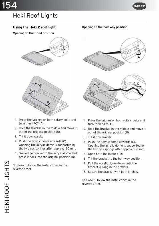
154H
EKI R
OO
F LI
GH
TS
Heki Roof Lights
Using the Heki 2 roof light
Opening to the tilted position
1. Press the latches on both rotary bolts and turn them 90° (A).
2. Hold the bracket in the middle and move it out of the original position (B).
3. Tilt it downwards.
4. Push the acrylic dome upwards (C). Opening the acrylic dome is supported by the two gas springs after approx. 150 mm.
5. Swivel the bracket to the acrylic dome and press it back into the original position (D).
To close it, follow the instructions in the reverse order.
Opening to the half-way position
1. Press the latches on both rotary bolts and turn them 90° (A).
2. Hold the bracket in the middle and move it out of the original position (B).
3. Tilt it downwards.
4. Push the acrylic dome upwards (C). Opening the acrylic dome is supported by the two gas springs after approx. 150 mm.
5. Open both the latches (D).
6. Tilt the bracket to the half-way position.
7. Pull the acrylic dome down until the bracket is lying in the holders.
8. Secure the bracket with both latches.
To close it, follow the instructions in the reverse order.

155
HEK
I RO
OF
LIG
HTS
Using the Midi Heki
To Open
1. Push button (2) to release bar (1).
2. Push bar into one of the rest positions shown in fig. 5.
To Close
3. Complete the above steps in reverse.
Closing the roller blinds
1. Take hold of the recessed grip on the rod and pull it towards the rod on the other side with the pivot until they both click into one another.
2. Select the required position by moving the two latched-roller blinds at the same time.
Opening the roller blinds
1. Pull the roller blind so that the blind with the recessed grip is completely extended.
2. Separate the roller blinds by pressing the pivot.
3. Guide the roller blind back using the recessed grip. Do not let the roller blind spring back.
NOTE: There is a risk of damage due to a build-up of heat between the roller blind and the window. In strong sunlight only close the blackout roller blind two thirds of the way.

156H
EKI R
OO
F LI
GH
TS
Using the Mini Heki
To Open
1. Squeeze the black section of the handles down into the white section of the handles.
2. Push the roof light upwards.3. To achieve the tilt half opening position,
only push one side of the rooflight upwards.
4. To close repeat the above steps in reverse.
Roof light Maintenance
Clean roller blinds with mild soap and plenty of water.
NOTE: The roof dome may cloud over in bright sunshine. It will become clear again as soon as it cools down.
Safety
• If faults or disturbances occur, consult a specialist workshop immediately.
• Risk of breakage, do not tread on the acrylic dome.
• Before starting your journey, check that the roof window is locked properly.
• Before starting your journey, check the roof window for damage (such as tension cracks in the acrylic).
• Do not open the roof window while driving.• Do not open the window in strong wind or
rain.• Close the roof window if it rains or snows.• Do not leave the vehicle with the roof
window open.• Keep the roof window free of snow and ice.
Maintaining and cleaning the Heki Roof lights
NOTE: Do not use any sharp or hard objects for cleaning since they may damage the acrylic.
Only use cleaning agents that are approved by the manufacturer.
NOTE: It is recommended, that any elevating roofs be raised when the motorhome is used for habitation purposes.

157
THE
REM
IS W
IND
OW
BLI
ND
S
The Remis Window Blinds
Operating Your Motorhome Habitation Blinds ........................................................ 158
Cleaning ............................................................................................................................ 158
Remis Concertina Cab Blinds ....................................................................................... 159
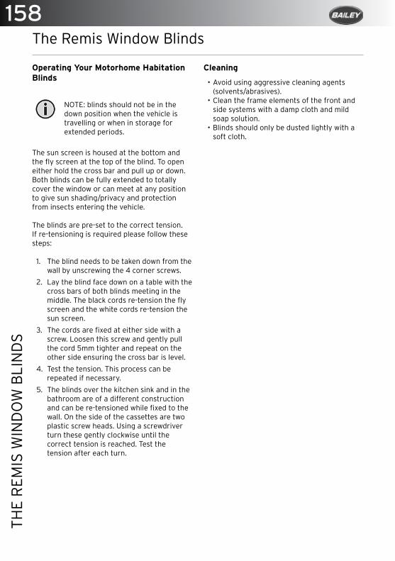
158TH
E R
EMIS
WIN
DO
W B
LIN
DS
The Remis Window Blinds
Operating Your Motorhome Habitation Blinds
NOTE: blinds should not be in the down position when the vehicle is travelling or when in storage for extended periods.
The sun screen is housed at the bottom and the fly screen at the top of the blind. To open either hold the cross bar and pull up or down. Both blinds can be fully extended to totally cover the window or can meet at any position to give sun shading/privacy and protection from insects entering the vehicle.
The blinds are pre-set to the correct tension.If re-tensioning is required please follow these steps:
1. The blind needs to be taken down from the wall by unscrewing the 4 corner screws.
2. Lay the blind face down on a table with the cross bars of both blinds meeting in the middle. The black cords re-tension the fly screen and the white cords re-tension the sun screen.
3. The cords are fixed at either side with a screw. Loosen this screw and gently pull the cord 5mm tighter and repeat on the other side ensuring the cross bar is level.
4. Test the tension. This process can be repeated if necessary.
5. The blinds over the kitchen sink and in the bathroom are of a different construction and can be re-tensioned while fixed to the wall. On the side of the cassettes are two plastic screw heads. Using a screwdriver turn these gently clockwise until the correct tension is reached. Test the tension after each turn.
Cleaning
• Avoid using aggressive cleaning agents (solvents/abrasives).
• Clean the frame elements of the front and side systems with a damp cloth and mild soap solution.
• Blinds should only be dusted lightly with a soft cloth.
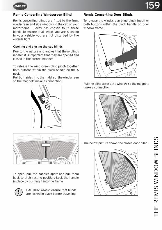
159
THE
REM
IS W
IND
OW
BLI
ND
S
Remis Concertina Door Blinds
To release the windscreen blind pinch together both buttons within the black handle on door window frame.
Pull the bilnd across the window so the magnets make a connection.
The below picture shows the closed door bilnd.
Remis Concertina Windscreen Blind
Remis concertina blinds are fitted to the front windscreen and side windows in the cab of your motorhome. Bailey has chosen to fit these blinds to ensure that when you are sleeping in your vehicle you are not disturbed by the outside light.
Opening and closing the cab blinds
Due to the nature and angles that these blinds inhabit, it is important that they are opened and closed in the correct manner.
To release the windscreen blind pinch together both buttons within the black handle on the A post.Pull both sides into the middle of the windscreen so the magnets make a connection.
To open, pull the handles apart and pull them back to their resting position. Lock the handle in place by pushing it into the frame.
CAUTION: Always ensure that blinds are locked in place before travelling.


161
THE
FIA
MM
A A
WN
ING
The Fiamma Awning
Opening The Fiamma Awning ....................................................................................... 161
Closing The Fiamma Awning ........................................................................................ 163
Maintenance..................................................................................................................... 163
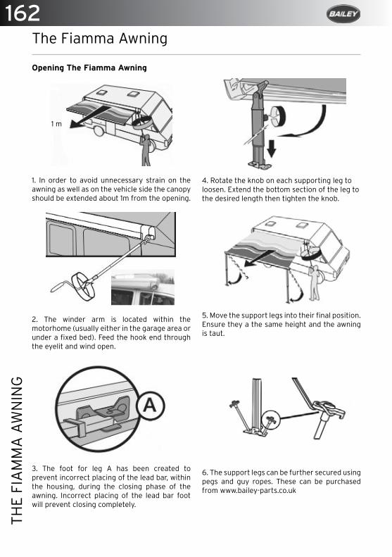
162TH
E FI
AM
MA
AW
NIN
G
The Fiamma Awning
Opening The Fiamma Awning
1. In order to avoid unnecessary strain on the awning as well as on the vehicle side the canopy should be extended about 1m from the opening.
2. The winder arm is located within the motorhome (usually either in the garage area or under a fixed bed). Feed the hook end through the eyelit and wind open.
3. The foot for leg A has been created to prevent incorrect placing of the lead bar, within the housing, during the closing phase of the awning. Incorrect placing of the lead bar foot will prevent closing completely.
1 m
4. Rotate the knob on each supporting leg to loosen. Extend the bottom section of the leg to the desired length then tighten the knob.
5. Move the support legs into their final position. Ensure they a the same height and the awning is taut.
6. The support legs can be further secured using pegs and guy ropes. These can be purchased from www.bailey-parts.co.uk
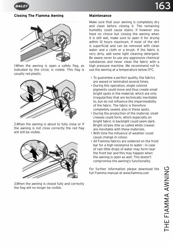
163
THE
FIA
MM
A A
WN
ING
Closing The Fiamma Awning
1.When the awning is open a safety flag, as indicated by the clrcle, is visible. This flag is usually red plastic.
2.When the awning is about to fully close or if the awning is not close correctly the red flag will still be visible.
3.When the awning is closed fully and correctly the flag will no longer be visible.
Maintenance
Make sure that your awning is completely dry and clean before closing it. The remaining humidity could cause stains. If however you have no choice but closing the awning when it is still wet, make sure to open it for drying within 12 hours maximum. If most of the dirt is superficial and can be removed with clean water and a cloth or a brush. If the fabric is very dirty, add some light cleaning detergent. Be aware never to use any aggressive chemical substances and never clean the fabric with a high pressure machine. We recommend not to use the awning at a temperature below 0°C.
• To guarantee a perfect quality, the fabricsare waxed or laminated several times.
• During this operation, single coloredpigments could move and thus create smallbright spots in the material, which are onlyirregularities that are technically inevitableto, but do not influence the impermeabilityof the fabric. The fabric is thereforecompletely sealed, also in these spots.
• During the production of the material, smallcreases could form, which especially onbright fabric in backlight could seem dark.Bright stripes (the so called white crease)are inevitable with these materials.
• With time the influence of weather couldcause change in colour.
• All Fiamma fabrics are soldered on the frontbar for a high resistance to water : in caseof rain little drops of water may form nearthe front bar and this may happen whenthe awning is open as well. This doesn’tcompromise the awning’s functionality.
For further information please download the full Fiamma manual at www.fiamma.com

Proud Suppliers To Bailey Of Bristol
visit ww
w.m
orlan
d-u
k.com
Mo
rland
, Un
it 4, B
uttin
gton
Cro
ss Enterp
rise Park,
Welsh
po
ol, P
ow
ys SY21
8SL
Tel +44
(0)1
93
8 5
51
98
0 Fax +4
4 (0
)19
38
55
4 1
74
Em
ail: info
@m
orlan
d-u
k.com
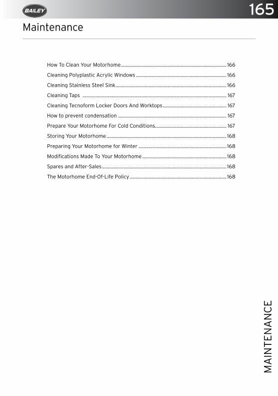
165
MA
INTE
NA
NC
E
Maintenance
How To Clean Your Motorhome ................................................................................... 166
Cleaning Polyplastic Acrylic Windows ....................................................................... 166
Cleaning Stainless Steel Sink ....................................................................................... 166
Cleaning Taps ................................................................................................................. 167
Cleaning Tecnoform Locker Doors And Worktops .................................................. 167
How to prevent condensation ..................................................................................... 167
Prepare Your Motorhome For Cold Conditions. ....................................................... 167
Storing Your Motorhome .............................................................................................. 168
Preparing Your Motorhome for Winter ..................................................................... 168
Modifications Made To Your Motorhome .................................................................. 168
Spares and After-Sales .................................................................................................. 168
The Motorhome End-Of-Life Policy ............................................................................ 168
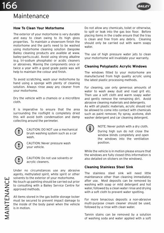
166M
AIN
TEN
AN
CE
Maintenance
How To Clean Your Motorhome
The exterior of your motorhome is very durable and easy to clean owing to its high gloss properties. To maintain a showroom finish the motorhome and the parts need to be washed using motorhome cleaning solution (bespoke Bailey cleaning products are avalible at www.bailey-parts.co.uk). Avoid using strong alkaline (e.g. tri-sodium phosphate) or acidic cleaners or abrasives. Waxing the components once or twice a year with a good grade paste wax will help to maintain the colour and finish.
To avoid scratching, wash your motorhome by hand using a sponge with plenty of cleaning solution. Always rinse away any cleaner from your motorhome.
Dry the vehicle with a chamois or a microfibre cloth.
It is imperative to ensure that the area surrounding the rooflight is completely dried this will avoid both condensation and damp collecting around the perimeter.
CAUTION: DO NOT use a mechanical brush washing system such as a car wash.
CAUTION: Never pressure wash your vehicle.
CAUTION: Do not use solvents or acrylic cleaners.
Under no circumstances use any abrasive agents, methylated spirit, white spirit or other solvents to the exterior of your motorhome.No touch up painting should be carried out prior to consulting with a Bailey Service Centre for approved methods.
All items stored in the gas bottle storage locker must be secured to prevent impact damage to the inside of the body panel when the vehicle is in motion.
Do not allow any chemicals, toilet or otherwise, to spill or leak into the gas box floor. Before placing items in the cradle ensure that the tray is clean and free from any debris. Cleaning should only be carried out with warm soapy water.
The use of high pressure water jets to clean your motorhome will invalidate your warranty.
Cleaning Polyplastic Acrylic Windows
The windows fitted to your motorhome are manufactured from high quality acrylic using the latest plastic processing methods.
For cleaning, use only generous amounts of water to wash away dust and road grit etc. Then use a soft cloth and warm soapy water and gently remove the remaining dirt. Avoid abrasive cleaning materials and detergents.As with all plastic materials, acrylic should not be allowed to come into contact with chemicals such as paint remover, fly spray, acetone, dish washer detergent and car cleaning detergent.
NOTE: Never polish with a dry cloth.
During high sun do not close the window blinds completely and open the windows into the ventilation position.
While the vehicle is in motion please ensure that the windows are fully closed (this information is also detailed on stickers on the windows).
Cleaning Stainless Steel Sink
The stainless steel sink will need little maintenance other than cleaning immediately after use. Most deposits can be removed by washing with soap or mild detergent and hot water, followed by a clean water rinse and drying with a soft cloth to prevent water spotting.
For more tenacious deposits a non-abrasive multi-purpose cream cleaner should be used, followed by a rinse with clean water.
Tannin stains can be removed by a solution of washing soda and water applied with a soft

167
MA
INTE
NA
NC
E
cloth/sponge followed by a rinse with clean water. To remove any residues and dry with a soft cloth.
When cleaning with anything other than water, be careful not to get the solution onto your kitchen worktop.
Scratching will be most noticeable on highly polished components. These marks are usually only superficial and can be removed with a proprietary stainless steel cleaner/polish. If the surface has a directional polished grain always clean along the grain and not across it.
Always avoid bleach and trigger dispense products and never use wire wool or leave wet cloths, pads or containers on the surface as they may form water marks.
WARNING: To preserve the appearance of your appliance we recommend not to store plastic bowls or mats in the sink. This is particularly the case when travelling because vehicle movement may cause the plastic bowl to vibrate/rub against the surface and leave marks.
Cleaning Taps
Clean and wipe with a soft soapy sponge, then rinse and wipe dry. Do not use an abrasive cleaner, scouring pad, powder or wire wool to clean the tap and shower mixer. Do not use any de-scaling agent.If you live in a hard water area, limescale may build up around the spout of your tap. Clean this off with either lemon juice or vinegar. Do not attempt to remove this with either a knife or any other sharp implement as this will damage the surface.
Cleaning Tecnoform Locker Doors And Worktops
Wipe the doors with a soft, slightly damp cloth (not wet) and then dry them with a dry cloth.Worktops can be wiped with a wet cloth and are more resistant to water than the locker doors.
CAUTION: Petrol, thinners, abrasive products, chemically treated cloths and detergents may damage doors and should not be used.
How to prevent condensation
Condensation is the change of water from its gaseous form (water droplets) into its liquid form. Condensation generally occurs in the atmosphere when warm air rises, cools and loses its capacity to hold water vapour. As a result, excess water vapour condenses to form droplets.Condensation normally occurs in the winter when the motorhome is cold and skylights, windows and doors are opened less often; this means that moist air cannot escape. It is important to try and provide ventilation so that moist air can escape and to use the heating responsibly.
Provide ventilation so that warm air can escape:
• Open a window to provide good ventilation of kitchens when washing, cooking or drying damp cloths is essential.
• If it is not possible to use the space heater, open the skylights or windows slightly but keep the main door closed as much as possible.
• After showering, keep the bathroom door closed and the window or the skylight open long enough for the room to dry.
Prepare Your Motorhome For Cold Conditions.
Your motorhome is fully climatized having achieved the BS EN 1646-1:2004+A1:2008 standard climatic testing to Grade 3 standard.
• Make sure that all plumbing pipes, drains, and water supply appliances within the motorhome are properly drained.
• Try to cover as much as possible, the underside of the motorhome to prevent snow from collecting and packing up underneath. This will help to prevent damage to the tyres due to the weather.
Storing Your Motorhome
The following applies whenever your motorhome is stored, particularly during winter months.
• Do not leave your vehicle near trees or latch-type gates due to possible wind damage.

168M
AIN
TEN
AN
CE
• Keep any grass around the floor of the motorhome short to maintain airflow and stop any possible damp getting into it.
• It is advised that the motorhome is ventilated regularly throughout the winter storage period, opening windows, doors and rooflights where possible.
• All moving parts should be checked for free operation.
• Clean all cooking appliances and the refrigerator before parking up the vehicle.
• Charge up the on-board battery every 2 months.
• Leave the refrigerator door open. Leave the furniture and locker doors open to allow air to circulate fully.
• Ensure that the entire water system is thoroughly drained.
Preparing Your Motorhome for Winter
Freezing in winter may cause damage to the Whale tap. To avoid this damage, ensure that the system is completely drained:
• Drain the fresh water tank using either the pump or a drain valve.
• Turn the pump on and open all taps and the shower mixer (including the drain valve) and allow the pump to purge the water from the system.
• Turn off the power isolator switch for the water pump.
• Remember to leave all outlets open to avoid any damage.
• Lift up the lever of every tap and leave it in its central position.
Modifications Made To Your Motorhome
Owners need to be aware that carrying out DIY modifications to your motorhome may, in certain circumstances, invalidate the warranty cover and could also affect the safety and structure of the vehicle.
Never allow modification of electrical or LPG systems and appliances except by qualified persons. Care should be taken that any additional equipment or appliances are installed in accordance with the appliance/equipment manufacturer’s instructions.
Spares and After-Sales
There are numerous parts and accessories available for your motorhome either from your Bailey retailer or through the Bailey Parts website (www.bailey-parts.co.uk).
You are more than welcome to contact the parts website for anything you may require. However, if it is a safety or warranty critical item, you will need to obtain it from your Bailey retailer who will fit the component for you.
In the interest of safety, replacement parts for an appliance shall conform to the appliance manufactuer’s specifications and should be fitted by him or his authorised.
The Motorhome End-Of-Life Policy
After many years in service you may decide that your motorhome has become beyond economic repair and should be disposed of. Please ensure that you comply with the end-of-life vehicle legislation and take it to an authorised treatment facility where it will be properly dealt with to minimise any negative environmental impact. The transaction will be logged by the DVLA, identifying that you are no longer the owner of the vehicle.
169
WA
RR
AN
TY
Warranty
Motorhome Warranty Cover......................................................................................... 170
The Three Warranties .................................................................................................... 170
Customer Support .......................................................................................................... 170
Terms and Conditions ..................................................................................................... 171
Cover ................................................................................................................................. 170
Term .................................................................................................................................... 171
Repairs ............................................................................................................................... 171
Warranty Registration ....................................................................................................173
170W
AR
RA
NTY
Warranty
Motorhome Warranty Cover
Total satisfaction is the top priority at Bailey and the quality ethos extends to the after-sales service and manufacturer’s warranty that comes with every new Bailey motorhome. In this way we not only ensure long-term peace of mind but also enhance the resale value of your investment.
Your Bailey motorhome has three warranties:
3 Year Base Vehicle Warranty – Provided by Peugeot
The Bailey motorhome is a coach-built model which utilises a Peugeot base vehicle. Peugeot provides a manufacturer’s warranty for the base vehicle supplied which is subject to the terms and conditions laid down in their handbook. All enquiries relating to this warranty should be directed to your local Peugeot Service Agent.
6 Year Bodyshell Integrity Waranty –Provided by Bailey
The Bailey Alu-Tech motorhome is covered by a six (6) year Bodyshell Integrity Warranty. This cover extends to any structural degradation to the bodyshell that arises as a result of water ingress through any permanently sealed seams or joints (with the exception of exclusions stated in the terms and conditions.)
Warranty Extension
An additional four (4) year extension to the standard Bodyshell Integrity Warranty cover (making 10 years’ cover in total) is available as a cost option. Please ask your supplying Bailey retailer for more information.
3 Year Manufacturer’s Warranty – Provided by Bailey
For a period of three (3) years from the initial date of purchase, Bailey offers a comprehensivewarranty on all parts and components used in the construction of the Bailey motorhome chassis and habitation area, as well as full coverage for any manufacturing faults forming
part of the original specification of the Bailey motorhome with the following specified exceptions: The following items are covered for one (1) year from the date of first registration:
> Leisure batteries
The following items are not covered:
> Replacement bulbs, light emitting diodes,fluorescent tubes or fuses
> General maintenance.
Warranty Extension
An additional three (3) year extension to the standard Manufacturer’s Warranty cover formechanical and electrical components of a leisure vehicle both external and internal (making 6 years cover in total) is available as a cost option. Please ask your supplying Bailey retailer for more information.
Customer Support
In the unusual event of something going wrong your first contact should always be yoursupplying retailer. Approved Bailey retailers enjoy industry-leading after-sales supportservice from the manufacturer and they will be able to offer all the help you need torectify any problems that may exist. It should be noted that Bailey retailers sell our productsof their own choice and not as agents of Bailey. Accordingly they have no authority to bindBailey or make representation or undertaking whatsoever on behalf of Bailey.
Terms and Conditions
Defects in the base vehicle are covered by the base vehicle manufacturer’s warranty and anyissues with it should be referred to one of the base vehicle manufacturer’s agents.The Bailey Warranty Cover set out above is offered subject to the following simple terms and conditions.
Cover
During the term of the Warranty Cover, subject to these terms and conditions, Bailey

171
WA
RR
AN
TY
will, through an Authorised Service Centre, at its option repair or replace all parts and components of the Bailey motorhome that are included in the Warranty Cover and which suffer a defect in manufacturer or workmanship. An Authorised Service Centre means either Bailey itself, a Bailey Approved Retailer or a Bailey Approved Service Centre. Any part which is replaced becomes the property of Bailey. Any replacement parts are covered for the unexpired term of the Warranty Cover.
Term
The initial duration of the Bodyshell Integrity Warranty is six (6) years extendable to ten (10) years and the duration of the Manufacturer’s Warranty is three (3) years extendable to six (6) years, in both cases starting from the original purchase date of the Bailey motorhome. It is a condition of the warranty that an annual service is performed on the Bailey motorhome in accordance with the service plan. Failure to comply with this term will invalidate the warranty.The unexpired term of the Warranty Cover on your Bailey motorhome may only be assigned, transferred or novated to subsequent owners with Bailey consent (not to be unreasonably withheld) and on payment to Bailey of a transfer fee of £35. Transfer can only be made within the first (3) months of subsequent ownership and full documentary evidence that the Bailey motorhome conversion has been serviced annually must be provided at the time of assignment in accordance with the terms and conditions detailed above.
Repairs
The Bailey motorhome must undergo a full annual service and inspection, including a moisture survey, carried out, subject to the conditions specified below, by an Authorised Service Centre. The final annual service in the warranty period must be carried out before the end of that warranty period, but all other annual services may be carried out within six (6) weeks either side of each anniversary of the original purchase date. The original VAT invoices must be retained as proof that these annual inspections have been carried out. During the first three (3) years of the Warranty Cover, all annual inspections and repairs must
be carried out either by Bailey itself or by an approved Bailey Service Centre or Agent. Thereafter, due to the technical nature of an Alu-Tech constructed Bailey motorhome, annual inspections and repairs may be carried out by any workshop or repair centre approved by the National Caravan Council.Where an annual inspection identifies that repairs to the Bailey motorhome are necessary, the Bailey motorhome must be made available for repair within six (6) weeks of the date of inspection for the purpose of carrying out the repair work.No repairs, including the fitting of any replacement unit, may be undertaken or commenced under the terms of the Warranty Cover unless prior authorisation is obtained from Bailey via an authorised Bailey retailer or Service Centre. No liability will exist with regard to any warranty claims not authorised in this way.Bailey reserve the right to examine the Bailey motorhome before any repairs commence or any replacement part is fitted.
Registration and Use
The Warranty Registration Form must have been sent to Bailey within six (6) weeks of the original purchase date. It is the responsibility of the Bailey retailer to forward this information to Bailey. This is part of the terms of trading that the Bailey retailer has with Bailey.
The Bailey motorhome shall:
Only be used for its original and intended purpose and shall not be subjected to any treatment or conditions which could reasonably be foreseen to cause or result in damage to the Bailey motorhome or excessive wear and tear.Not be put out to hire, reward or any other commercial use, nor used in any race, competitions or rallies whether timed, official or otherwise.
Exclusions and Liability
Bailey’s liability under this warranty shall be limited to supplying the reasonable cost of labour and materials required for repair or replacement of faulty parts or components. Bailey shall be entitled to charge for any repair work which is necessitated by virtue of any loss or damage caused by its owner’s negligence or default or incurred as a result of any
172W
AR
RA
NTY
modifications made to the Bailey motorhome. This warranty does not cover repair costs other than labour and materials.
The Warranty Cover does not include
> Repair or replacement of parts, components, seams or panels which are not part of the original construction of the Bailey motorhome, or which have been tampered with or undergone unauthorised modifications, or which have been repaired otherwise than by an Authorised Service Centre.
> Parts or components other than those specifically listed in the Bodyshell Integrity Warranty and Manufacturer’s Warranty descriptions set out above.
> General maintenance or components failing due to fair wear and tear or normal deterioration.
> Repairs necessitated by lack of routine or regular maintenance. Particular attention is drawn to the owner’s handbook and service handbook supplied with theBailey motorhome and any maintenance instructions or notices published from time to time by Bailey relating to the proper care and maintenance of the Bailey motorhome.
> Structural degradation or other damage caused by water ingress through non permanently sealed seams or joints (such as, without limitation, around windows, hatches, doors and rooflights), beyond the initial 36 months of the Manufacturer’s Warranty.
> Maintenance activities including the adjustment of doors, catches and window blinds, servicing of appliances or cleaning.
> Maintenance activities related to the reduction of noise vibration and harshness.
No Liability will be accepted for:
> Damage caused by neglect or abuse,corrosion, intrusion of foreign or deleterioussubstances, lack of servicing, over-heating,freezing, or the continued use of the Baileymotorhome after a fault has becomeevident.
> Any loss or damage caused by parts notcovered by this Warranty Cover, includingsoft furnishings or trim.
> Any accidental or fire damage or any lossesincurred by accident or fire.
> Transport costs to and from point of repair.
> Damage caused by animals, rodents orother pests.
Bailey will only be liable for costs which are incurred as a direct consequence of the event,defect or fault leading to the claim being made under warranty. No liability will be acceptedfor any loss or damage (such as loss of income or revenue, or loss of business or profits),costs, expenses, or other claims for compensation howsoever arising which was not reasonably foreseeable by both parties when the Bailey motorhome was originally purchased. Bailey will not be liable for any loss or damage suffered by third parties, nor for bodily injury caused by the company’s negligence.
Nothing in this warranty shall limit in any way Bailey’s liability for death or personal injurycaused by their negligence or fraud or fraudulent misrepresentation or for any matter for which it would be illegal for us to exclude, or attempt to exclude.
The purchaser has statutory rights in addition to this warranty and this warranty does not affect those statutory rights.
This warranty shall be governed by and construed in accordance with the laws of England and the parties irrevocably submit to the non-exclusive jurisdiction of the courts of England.

173
WA
RR
AN
TY
Warranty Registration
The supplying retailer must explain the warranty terms and conditions to you, and complete the warranty registration process on-line. Your warranty will start on the day that the vehicle is first registered in the UK or 12 months from the date on which the vehicle was invoiced to the supplying retailer, whichever is the earlier.
The name and address of the warranty provider is:Bailey Caravans Limited, South Liberty Lane, Bristol, BS3 2SS
Warranty Registration:
The supplying retailer must explain the warranty terms and conditions to you and complete the warranty registration process on-line to ensure that your warranty is active. Your warranty will start on the day that the vehicle is first registered in the UK or 12 months from the date on which the vehicle was invoiced to the supplying retailer, whichever is the earlier.
Please sign below to verify that this has been done.
Customer’s Signature: ........................................... Retailer’s Signature:.................................................
Date: ......................................................................... Date: ............................................................................
SERVICE MANUAL


Service Manual
Welcome to your new Bailey Motorhome.
This Service Manual is a record of your motorhome’s service history. It includes technical information for your reference. It should be read in conjunction with the Motorhome Owner’s Manual.
Your motorhome is designed to give you many years of use. However, regular maintenance is necessary to ensure trouble-free usage. Your Bailey retailer is equipped to offer service and repair work facilities as well as supplying any spare parts that you may require. All enquiries regarding your motorhome should therefore be addressed in the first instance to the retailer from whom you purchased the vehicle.
Manufactured byBailey of Bristol Ltd, South Liberty Lane, Bristol, BS3 2SS
© Bailey of Bristol 2016. All rights reserved.No Part of this document may be reproduced or transmitted in any form or by any means, electronic or mechanical, for any purpose, without the express permission of Bailey of Bristol Ltd.
Motorhome Service Schedule
In order to validate the factory backed warranty package, your motorhome must be serviced by an approved Bailey Service centre every 12 months (or 6 weeks eitherside of the anniversary of purchase) in accordance with the NCC recommended service schedule.
A full listing of the current Approved Bailey Centres can be found on the Retailer Network pages of our website www.baileyofbristol.co.uk
WARNING: Under no circumstance should the bodyshell fixings be tampered with or adjusted by the motorhome owner. Any tampering or adjustment will invalidate the warranty.
Standard Moisture Survey For Alu-Tech Construction Motorhomes
A moisture survey must be carried out using a calibrated moisture meter every 12 months by an Approved Bailey Service centre.
Readings should be obtained from the floor section of the motorhome in positions where the holes created by the meter’s probes are not visible e.g. behind seals, in bed boxes or in cupboard bases. It is important to make sure that the probes are free of moisture and the
surface of the floor is free from condensation.
Readings below 20% are considered acceptable. Readings greater than 20% will identify areas that need further investigation and possible remedial work.
All other parts of the body of an Alu-Tech motorhome should be checked visually for moisture ingress.
Thermal Insulation Grade
All Bailey Alu-Tech Motorhomes are manufactured and approved by the NCC to EN1646-1 thermal insulation and heating classification Grade 3. This has been approved using the motorhome space heater (Advance) or Alde wet system (Autograph) using both the electric and gas combined as the heating method.
Grade 3 is classified as being able to achieve an average temperature difference of 35 °C between the inside of the motorhome and the outside temerature when the outside temperature is -15°C.
Repairs
Repairs to the AL-KO AMC componentsincluding the axle assembly may only becarried out by specialist workshops.
3

Motorhome Overview
4
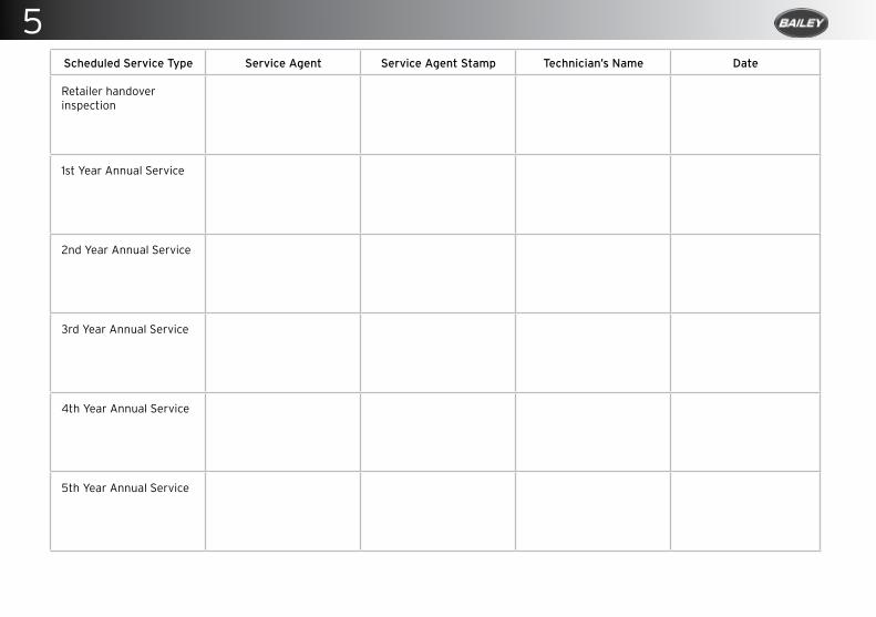
Scheduled Service Type Service Agent Service Agent Stamp Technician’s Name Date
Retailer handover inspection
1st Year Annual Service
2nd Year Annual Service
3rd Year Annual Service
4th Year Annual Service
5th Year Annual Service
5
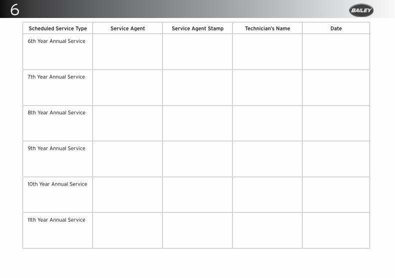
Scheduled Service Type Service Agent Service Agent Stamp Technician’s Name Date
6th Year Annual Service
7th Year Annual Service
8th Year Annual Service
9th Year Annual Service
10th Year Annual Service
11th Year Annual Service
6

Scheduled Service Type Service Agent Service Agent Stamp Technician’s Name Date
12th Year Annual Service
13th Year Annual Service
14th Year Annual Service
15th Year Annual Service
16th Year Annual Service
17th Year Annual Service
7
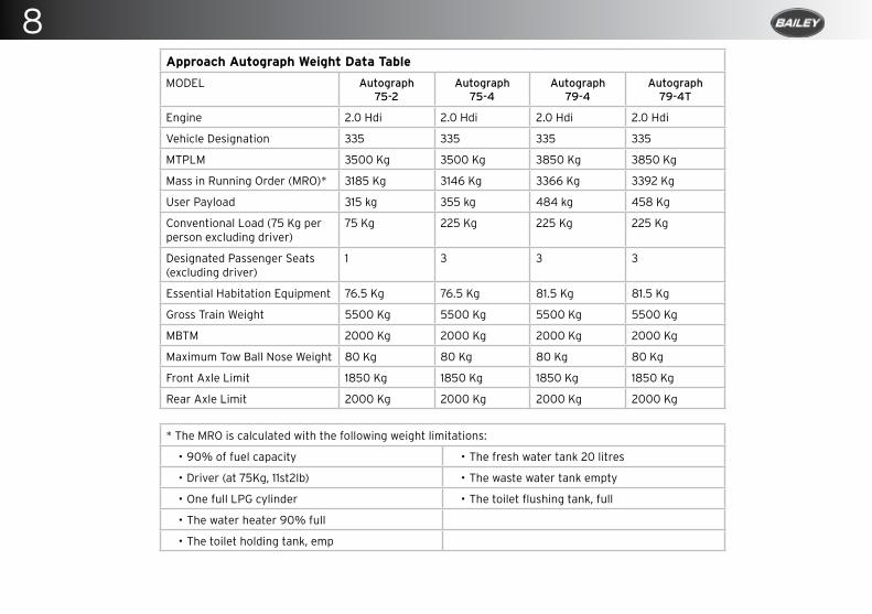
Approach Autograph Weight Data Table
MODEL Autograph75-2
Autograph75-4
Autograph79-4
Autograph79-4T
Engine 2.0 Hdi 2.0 Hdi 2.0 Hdi 2.0 Hdi
Vehicle Designation 335 335 335 335
MTPLM 3500 Kg 3500 Kg 3850 Kg 3850 Kg
Mass in Running Order (MRO)* 3185 Kg 3146 Kg 3366 Kg 3392 Kg
User Payload 315 kg 355 kg 484 kg 458 Kg
Conventional Load (75 Kg per person excluding driver)
75 Kg 225 Kg 225 Kg 225 Kg
Designated Passenger Seats (excluding driver)
1 3 3 3
Essential Habitation Equipment 76.5 Kg 76.5 Kg 81.5 Kg 81.5 Kg
Gross Train Weight 5500 Kg 5500 Kg 5500 Kg 5500 Kg
MBTM 2000 Kg 2000 Kg 2000 Kg 2000 Kg
Maximum Tow Ball Nose Weight 80 Kg 80 Kg 80 Kg 80 Kg
Front Axle Limit 1850 Kg 1850 Kg 1850 Kg 1850 Kg
Rear Axle Limit 2000 Kg 2000 Kg 2000 Kg 2000 Kg
* The MRO is calculated with the following weight limitations:
• 90% of fuel capacity • The fresh water tank 20 litres
• Driver (at 75Kg, 11st2lb) • The waste water tank empty
• One full LPG cylinder • The toilet flushing tank, full
• The water heater 90% full
• The toilet holding tank, emp
8
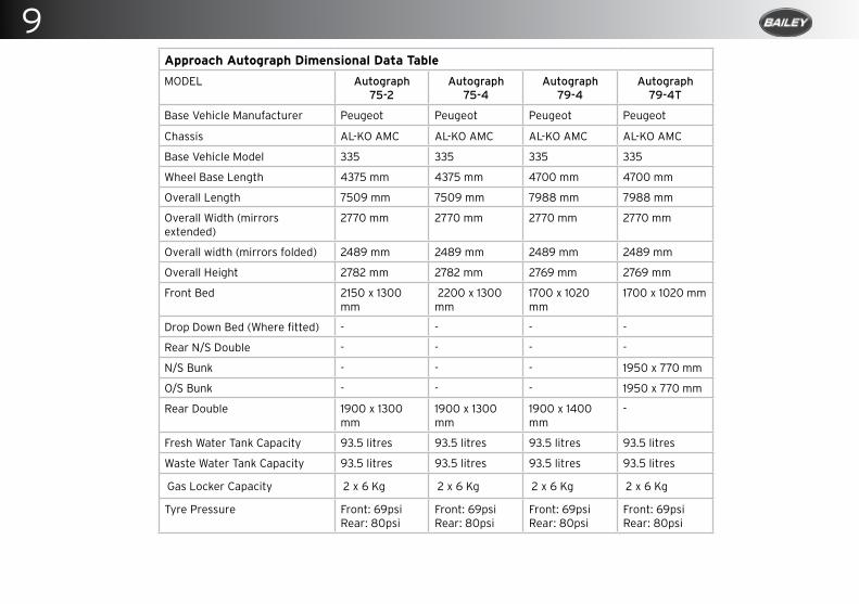
Approach Autograph Dimensional Data Table
MODEL Autograph 75-2
Autograph 75-4
Autograph 79-4
Autograph 79-4T
Base Vehicle Manufacturer Peugeot Peugeot Peugeot Peugeot
Chassis AL-KO AMC AL-KO AMC AL-KO AMC AL-KO AMC
Base Vehicle Model 335 335 335 335
Wheel Base Length 4375 mm 4375 mm 4700 mm 4700 mm
Overall Length 7509 mm 7509 mm 7988 mm 7988 mm
Overall Width (mirrors extended)
2770 mm 2770 mm 2770 mm 2770 mm
Overall width (mirrors folded) 2489 mm 2489 mm 2489 mm 2489 mm
Overall Height 2782 mm 2782 mm 2769 mm 2769 mm
Front Bed 2150 x 1300 mm
2200 x 1300 mm
1700 x 1020 mm
1700 x 1020 mm
Drop Down Bed (Where fitted) - - - -
Rear N/S Double - - - -
N/S Bunk - - - 1950 x 770 mm
O/S Bunk - - - 1950 x 770 mm
Rear Double 1900 x 1300 mm
1900 x 1300 mm
1900 x 1400 mm
-
Fresh Water Tank Capacity 93.5 litres 93.5 litres 93.5 litres 93.5 litres
Waste Water Tank Capacity 93.5 litres 93.5 litres 93.5 litres 93.5 litres
Gas Locker Capacity 2 x 6 Kg 2 x 6 Kg 2 x 6 Kg 2 x 6 Kg
Tyre Pressure Front: 69psiRear: 80psi
Front: 69psiRear: 80psi
Front: 69psiRear: 80psi
Front: 69psiRear: 80psi
9
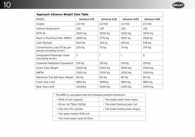
Approach Advance Weight Data Table
MODEL Advance 615 Advance 635 Advance 640 Advance 665
Engine 2.0 Hdi 2.0 Hdi 2.0 Hdi 2.0 Hdi
Vehicle Designation 335 335 335 335
MTPLM 3500 Kg 3500 Kg 3500 Kg 3500 Kg
Mass in Running Order (MRO)* 2696 Kg 2776 kg 2807 kg 2962 kg
User Payload 804 Kg 724 kg 693 kg 538 kg
Conventional Load (75 Kg per person excluding driver)
225 Kg 75 Kg 75 Kg 375 Kg
Designated Passenger Seats (excluding driver)
3 1 1 5
Essential Habitation Equipment 129 Kg 129 Kg 129 Kg 129 Kg
Gross Train Weight 5500 Kg 5500 Kg 5500 Kg 5500 Kg
MBTM 2000 Kg 2000 Kg 2000 Kg 2000 Kg
Maximum Tow Ball Nose Weight 80 Kg 80 Kg 80 Kg 80 Kg
Front Axle Limit 1850 Kg 1850Kg 1850 Kg 1850 Kg
Rear Axle Limit 2000Kg 2000 Kg 2000 Kg 2000 Kg
* The MRO is calculated with the following weight limitations:
• 90% of fuel capacity • The waste water tank empty
• Driver (at 75Kg, 11st2lb) • The toilet flushing tank, full
• One full LPG cylinder • The toilet holding tank, empty.
• The water heater 90% full
• The fresh water tank 20 litres
10
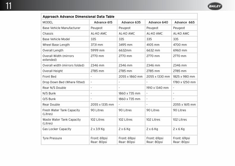
Approach Advance Dimensional Data Table
MODEL Advance 615 Advance 635 Advance 640 Advance 665
Base Vehicle Manufacturer Peugeot Peugeot Peugeot Peugeot
Chassis AL-KO AMC AL-KO AMC AL-KO AMC AL-KO AMC
Base Vehicle Model 335 335 335 335
Wheel Base Length 3731 mm 3495 mm 4105 mm 4700 mm
Overall Length 5999 mm 6632mm 6632 mm 6960 mm
Overall Width (mirrors extended)
2770 mm 2770 mm 2770 mm 2770 mm
Overall width (mirrors folded) 2346 mm 2346 mm 2346 mm 2346 mm
Overall Height 2785 mm 2785 mm 2785 mm 2785 mm
Front Bed - 2055 x 1860 mm 2055 x 1330 mm 1825 x 980 mm
Drop Down Bed (Where fitted) - - - 1780 x 1250 mm
Rear N/S Double - - 1910 x 1340 mm -
N/S Bunk - 1860 x 735 mm - -
O/S Bunk - 1860 x 735 mm - -
Rear Double 2055 x 1335 mm - - 2055 x 1615 mm
Fresh Water Tank Capacity (Litres)
90 Litres 90 Litres 90 Litres 90 Litres
Waste Water Tank Capacity (Litres)
102 Litres 102 Litres 102 Litres 102 Litres
Gas Locker Capacity 2 x 3.9 Kg 2 x 6 Kg 2 x 6 Kg 2 x 6 Kg
Tyre Pressure Front: 69psiRear: 80psi
Front: 69psiRear: 80psi
Front: 69psiRear: 80psi
Front: 69psiRear: 80psi
11
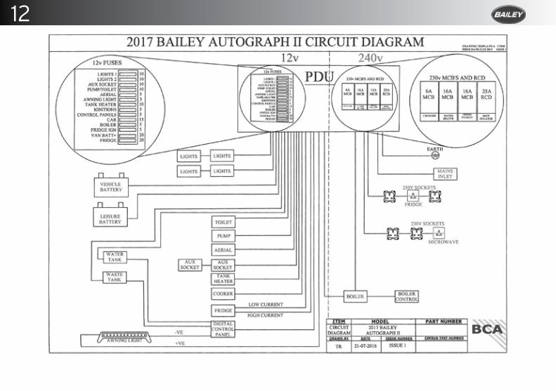
12
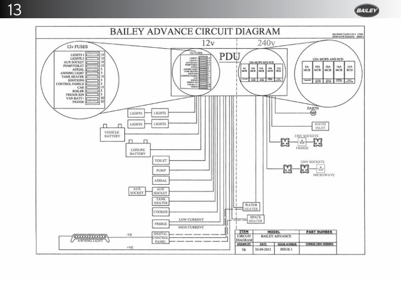
13
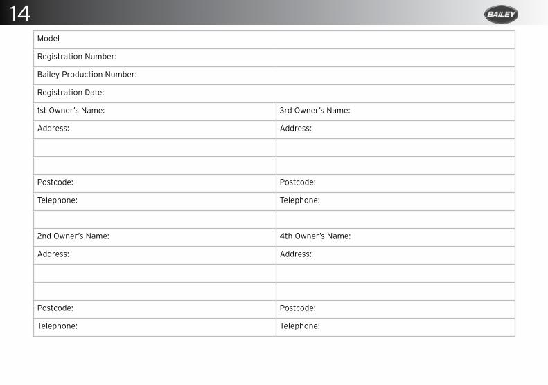
Model
Registration Number:
Bailey Production Number:
Registration Date:
1st Owner’s Name: 3rd Owner’s Name:
Address: Address:
Postcode: Postcode:
Telephone: Telephone:
2nd Owner’s Name: 4th Owner’s Name:
Address: Address:
Postcode: Postcode:
Telephone: Telephone:
14
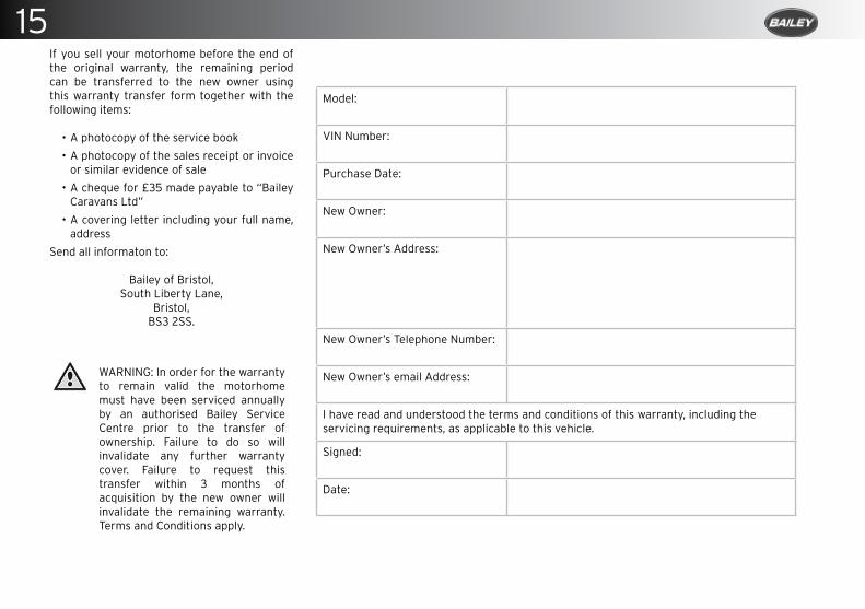
If you sell your motorhome before the end of the original warranty, the remaining period can be transferred to the new owner using this warranty transfer form together with the following items:
• A photocopy of the service book
• A photocopy of the sales receipt or invoice or similar evidence of sale
• A cheque for £35 made payable to “Bailey Caravans Ltd”
• A covering letter including your full name, address
Send all informaton to:
Bailey of Bristol,South Liberty Lane,
Bristol,BS3 2SS.
WARNING: In order for the warranty to remain valid the motorhome must have been serviced annually by an authorised Bailey Service Centre prior to the transfer of ownership. Failure to do so will invalidate any further warranty cover. Failure to request this transfer within 3 months of acquisition by the new owner will invalidate the remaining warranty. Terms and Conditions apply.
Model:
VIN Number:
Purchase Date:
New Owner:
New Owner’s Address:
New Owner’s Telephone Number:
New Owner’s email Address:
I have read and understood the terms and conditions of this warranty, including the servicing requirements, as applicable to this vehicle.
Signed:
Date:
15

If you sell your motorhome before the end of the original warranty, the remaining period can be transferred to the new owner using this warranty transfer form together with the following items:
• A photocopy of the service book
• A photocopy of the sales receipt or invoice or similar evidence of sale
• A cheque for £35 made payable to “Bailey Caravans Ltd”
• A covering letter including your full name, address
Send all informaton to:
Bailey of Bristol,South Liberty Lane,
Bristol,BS3 2SS.
WARNING: In order for the warranty to remain valid the motorhome must have been serviced annually by an authorised Bailey Service Centre prior to the transfer of ownership. Failure to do so will invalidate any further warranty cover. Failure to request this transfer within 3 months of acquisition by the new owner will invalidate the remaining warranty. Terms and Conditions apply.
Model:
VIN Number:
Purchase Date:
New Owner:
New Owner’s Address:
New Owner’s Telephone Number:
New Owner’s email Address:
I have read and understood the terms and conditions of this warranty, including the servicing requirements, as applicable to this vehicle.
Signed:
Date:
16

If you sell your motorhome before the end of the original warranty, the remaining period can be transferred to the new owner using this warranty transfer form together with the following items:
• A photocopy of the service book
• A photocopy of the sales receipt or invoice or similar evidence of sale
• A cheque for £35 made payable to “Bailey Caravans Ltd”
• A covering letter including your full name, address
Send all informaton to:
Bailey of Bristol,South Liberty Lane,
Bristol,BS3 2SS.
WARNING: In order for the warranty to remain valid the motorhome must have been serviced annually by an authorised Bailey Service Centre prior to the transfer of ownership. Failure to do so will invalidate any further warranty cover. Failure to request this transfer within 3 months of acquisition by the new owner will invalidate the remaining warranty. Terms and Conditions apply.
Model:
VIN Number:
Purchase Date:
New Owner:
New Owner’s Address:
New Owner’s Telephone Number:
New Owner’s email Address:
I have read and understood the terms and conditions of this warranty, including the servicing requirements, as applicable to this vehicle.
Signed:
Date:
17

If you sell your motorhome before the end of the original warranty, the remaining period can be transferred to the new owner using this warranty transfer form together with the following items:
• A photocopy of the service book
• A photocopy of the sales receipt or invoice or similar evidence of sale
• A cheque for £35 made payable to “Bailey Caravans Ltd”
• A covering letter including your full name, address
Send all informaton to:
Bailey of Bristol,South Liberty Lane,
Bristol,BS3 2SS.
WARNING: In order for the warranty to remain valid the motorhome must have been serviced annually by an authorised Bailey Service Centre prior to the transfer of ownership. Failure to do so will invalidate any further warranty cover. Failure to request this transfer within 3 months of acquisition by the new owner will invalidate the remaining warranty. Terms and Conditions apply.
Model:
VIN Number:
Purchase Date:
New Owner:
New Owner’s Address:
New Owner’s Telephone Number:
New Owner’s email Address:
I have read and understood the terms and conditions of this warranty, including the servicing requirements, as applicable to this vehicle.
Signed:
Date:
18