Embed Size (px)
Citation preview
Propane VaporWithdrawal
orNatural Gas
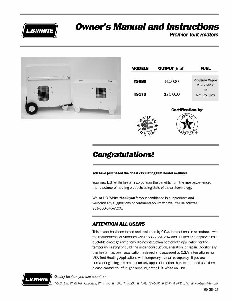
Congratulations!
You have purchased the finest circulating tent heater available.
Your new L.B. White heater incorporates the benefits from the most experiencedmanufacturer of heating products using state-of-the-art technology.
We, at L.B. White, thank you for your confidence in our products and welcome any suggestions or comments you may have...call us, toll-free, at 1-800-345-7200.
Owner's Manual and InstructionsPremier Tent Heaters
MODELS OUTPUT (Btuh) FUEL
TS080 80,000
TS170 170,000
Certification by:
150-26421
ATTENTION ALL USERS
This heater has been tested and evaluated by C.S.A. International in accordance withthe requirements of Standard ANSI Z83.7� CSA 2.14 and is listed and approved as aductable direct gas-fired forced-air construction heater with application for thetemporary heating of buildings under construction, alteration, or repair. Additionally,this heater has been application reviewed and approved by C.S.A. International forUSA Tent Heating Applications with temporary human occupancy. If you areconsidering using this product for any application other than its intended use, thenplease contact your fuel gas supplier, or the L.B. White Co., Inc.
WARNINGFire and Explosion Hazard
■ Not for home or recreational vehicle use.
■ Installation of this heater in a home orrecreational vehicle may result in a fire orexplosion.
■ Fire or explosions can cause propertydamage or loss of life.
FOR YOUR SAFETYIf you smell gas:1. Open windows.2. Don't touch electrical switches.3. Extinguish any open flame.4. Immediately call your gas supplier.
FOR YOUR SAFETYDo not store or use gasoline or otherflammable vapors and liquids in the vicinity ofthis or any other appliance.
WARNINGFire and Explosion Hazard
■ Keep solid combustibles a safe distanceaway from the heater.
■ Solid combustibles include wood, paper, orplastic products, building materials anddust.
■ Do not use the heater in spaces whichcontain or may contain volatile or airbornecombustibles.
■ Volatile or airborne combustibles includegasoline, solvents, paint thinner, dustparticles or unknown chemicals.
■ Failure to follow these instructions mayresult in a fire or explosion.
■ Fire or explosions can lead to propertydamage, personal injury or loss of life.
GENERAL HAZARD WARNING
■ Failure to comply with the precautions and instructions provided with this heater, can result in:— Death— Serious bodily injury or burns— Property damage or loss from fire or explosion— Asphyxiation due to lack of adequate air supply or carbon monoxide poisoning — Electrical shock
■ Read this Owner’s Manual before installing or using this product.
■ Only properly-trained service people should repair or install this heater.
■ Save this Owner’s Manual for future use and reference.
■ Owner’s Manuals and replacement labels are available at no charge. For assistance, contactL.B. White at 800-345-7200.
WARNING■ Proper gas supply pressure must be provided to the inlet of the heater.
■ Refer to data plate for proper gas supply pressure.
■ Gas pressure in excess of the maximum inlet pressure specified at the heater inlet can causefires or explosions.
■ Fires or explosions can lead to serious injury, death, or building damage.
■ Gas pressure below the minimum inlet pressure specified at the heater inlet may causeimproper combustion.
■ Improper combustion can lead to asphyxiation or carbon monoxide poisoning and thereforeserious injury or death.
2
SECTION PAGE
General Information . . . . . . . . . . . . . . . . . . . . . . . . . . . . . . . . . . . . . . . . . . . . . . . . . . . . . . . . . . . . . . . . . 4Heater Specifications . . . . . . . . . . . . . . . . . . . . . . . . . . . . . . . . . . . . . . . . . . . . . . . . . . . . . . . . . . . . . . . . 4Safety Precautions . . . . . . . . . . . . . . . . . . . . . . . . . . . . . . . . . . . . . . . . . . . . . . . . . . . . . . . . . . . . . . . . . . 5Installation Instructions
General . . . . . . . . . . . . . . . . . . . . . . . . . . . . . . . . . . . . . . . . . . . . . . . . . . . . . . . . . . . . . . . . . . . . . . . . 7Propane Gas Supply Sizing . . . . . . . . . . . . . . . . . . . . . . . . . . . . . . . . . . . . . . . . . . . . . . . . . . . . . . . . 8Sliding Handle Assembly (Premier 170). . . . . . . . . . . . . . . . . . . . . . . . . . . . . . . . . . . . . . . . . . . . . . 9Hose Hanger, Regulator Storage Bracket & Thermostat Storage Bracket. . . . . . . . . . . . . . . . . . . 9Wheel, Leg & Lifting Handle Assembly (Premier 170) . . . . . . . . . . . . . . . . . . . . . . . . . . . . . . . . . 10Leg Assembly (Premier 80) . . . . . . . . . . . . . . . . . . . . . . . . . . . . . . . . . . . . . . . . . . . . . . . . . . . . . . . 10Hose and Regulator Assembly . . . . . . . . . . . . . . . . . . . . . . . . . . . . . . . . . . . . . . . . . . . . . . . . . . . . 11Thermostat Assembly . . . . . . . . . . . . . . . . . . . . . . . . . . . . . . . . . . . . . . . . . . . . . . . . . . . . . . . . . . . 11Duct Kit Assembly . . . . . . . . . . . . . . . . . . . . . . . . . . . . . . . . . . . . . . . . . . . . . . . . . . . . . . . . . . . . . . 12Unit Diffuser Assembly . . . . . . . . . . . . . . . . . . . . . . . . . . . . . . . . . . . . . . . . . . . . . . . . . . . . . . . . . . 12End Diffuser Assembly . . . . . . . . . . . . . . . . . . . . . . . . . . . . . . . . . . . . . . . . . . . . . . . . . . . . . . . . . . 13Connecting Regulator to Gas Supply . . . . . . . . . . . . . . . . . . . . . . . . . . . . . . . . . . . . . . . . . . . . . . . 13
Start-Up Instructions . . . . . . . . . . . . . . . . . . . . . . . . . . . . . . . . . . . . . . . . . . . . . . . . . . . . . . . . . . . . . . . 14Shut-Down Instructions . . . . . . . . . . . . . . . . . . . . . . . . . . . . . . . . . . . . . . . . . . . . . . . . . . . . . . . . . . . . . 15Cleaning Instructions . . . . . . . . . . . . . . . . . . . . . . . . . . . . . . . . . . . . . . . . . . . . . . . . . . . . . . . . . . . . . . . 15Maintenance Instructions . . . . . . . . . . . . . . . . . . . . . . . . . . . . . . . . . . . . . . . . . . . . . . . . . . . . . . . . . . . 15Service Instructions
General . . . . . . . . . . . . . . . . . . . . . . . . . . . . . . . . . . . . . . . . . . . . . . . . . . . . . . . . . . . . . . . . . . . . . . . 16Motor and Fan Wheel . . . . . . . . . . . . . . . . . . . . . . . . . . . . . . . . . . . . . . . . . . . . . . . . . . . . . . . . . . . 16Air Proving Switch . . . . . . . . . . . . . . . . . . . . . . . . . . . . . . . . . . . . . . . . . . . . . . . . . . . . . . . . . . . . . . 17Igniter and Flame Sensor Assembly . . . . . . . . . . . . . . . . . . . . . . . . . . . . . . . . . . . . . . . . . . . . . . . . 17Testing the Manual Reset High Limit Switches . . . . . . . . . . . . . . . . . . . . . . . . . . . . . . . . . . . . . . . 18Burner Orifice and Gas Control Valve. . . . . . . . . . . . . . . . . . . . . . . . . . . . . . . . . . . . . . . . . . . . . . . 18
Gas Pressure Checks . . . . . . . . . . . . . . . . . . . . . . . . . . . . . . . . . . . . . . . . . . . . . . . . . . . . . . . . . . . . . . . 20Troubleshooting Information . . . . . . . . . . . . . . . . . . . . . . . . . . . . . . . . . . . . . . . . . . . . . . . . . . . . . . . . . 21Electrical Connection and Ladder Diagram, TS080. . . . . . . . . . . . . . . . . . . . . . . . . . . . . . . . . . . . . . . 27Electrical Connection and Ladder Diagram, TS170. . . . . . . . . . . . . . . . . . . . . . . . . . . . . . . . . . . . . . . 28Heater Component Function . . . . . . . . . . . . . . . . . . . . . . . . . . . . . . . . . . . . . . . . . . . . . . . . . . . . . . . . . 29Parts Identification
Parts Schematic and Parts ListPremier 80. . . . . . . . . . . . . . . . . . . . . . . . . . . . . . . . . . . . . . . . . . . . . . . . . . . . . . . . . . . . 30 & 31Premier 170. . . . . . . . . . . . . . . . . . . . . . . . . . . . . . . . . . . . . . . . . . . . . . . . . . . . . . . . . . . 32 & 33
Warranty Policy . . . . . . . . . . . . . . . . . . . . . . . . . . . . . . . . . . . . . . . . . . . . . . . . . . . . . . . . . . . . . . . . . . . . 34Replacement Parts and Service . . . . . . . . . . . . . . . . . . . . . . . . . . . . . . . . . . . . . . . . . . . . . . . . . . . . . . 34
Table of Contents
General Information
This Owner's Manual includes all options and accessoriescommonly used on this heater.
When calling for technical service assistance, or for otherspecif ic information, always have model number,configuration number and serial number available. Thisinformation is contained on the dataplate.
This manual will instruct you in the operation and care ofyour unit. Have your qualified installer review this manualwith you so that you fully understand the heater and how it functions.
The gas supply line installation, installation of the heater,and repair and servicing of the heater requires continuingexpert training and knowledge of gas heaters and shouldnot be attempted by anyone who is not so qualified. Seepage 6 for definition of the necessary qualifications.
Contact your local L.B. White distributor or the L.B. WhiteCo., Inc. for assistance, or if you have any questions aboutthe use of the equipment or its application.
The L.B. White Co., Inc. has a policy of continuous productimprovement. It reserves the right to change specificationsand design without notice.
3
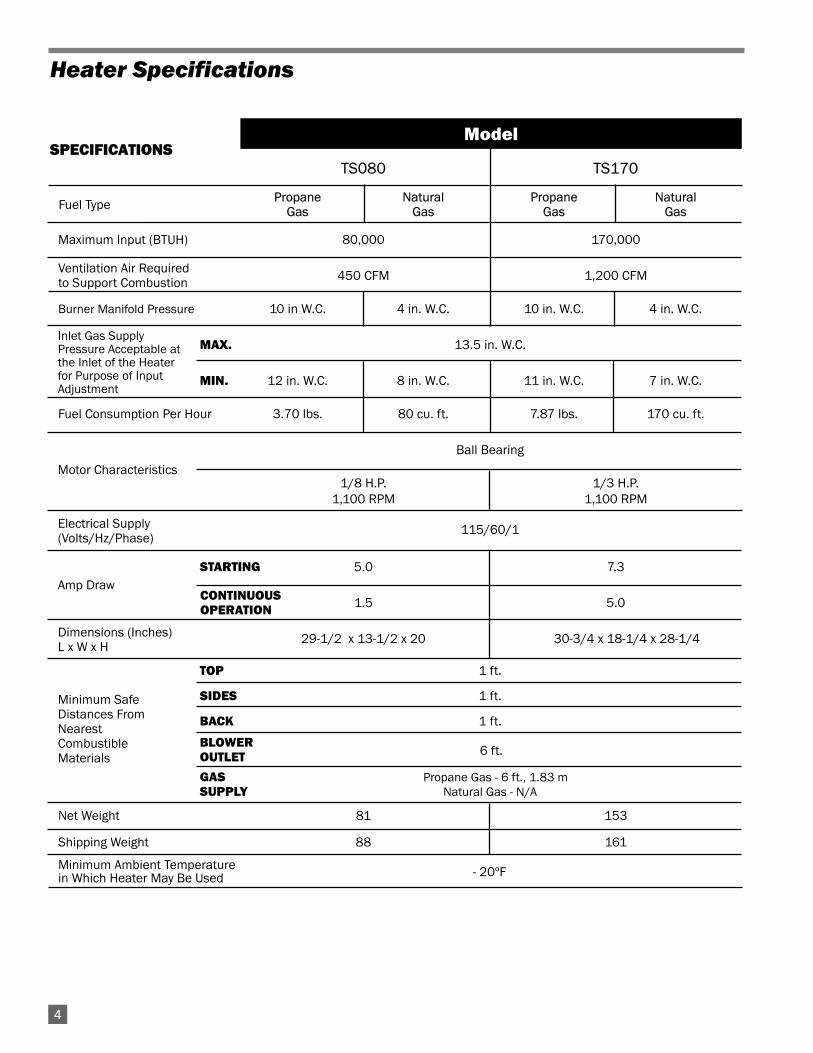
- 20ºF
SPECIFICATIONSTS080 TS170
Propane Natural Propane NaturalGas Gas Gas Gas
Maximum Input (BTUH) 80,000 170,000
450 CFM 1,200 CFM
Burner Manifold Pressure 10 in W.C. 4 in. W.C. 10 in. W.C. 4 in. W.C.
MAX. 13.5 in. W.C.
MIN. 12 in. W.C. 8 in. W.C. 11 in. W.C. 7 in. W.C.
Fuel Consumption Per Hour 3.70 lbs. 80 cu. ft. 7.87 lbs. 170 cu. ft.
Ball Bearing
1/8 H.P. 1/3 H.P.1,100 RPM 1,100 RPM
115/60/1
STARTING 5.0 7.3
1.5 5.0
29-1/2 x 13-1/2 x 20 30-3/4 x 18-1/4 x 28-1/4
TOP 1 ft.
SIDES 1 ft.
BACK 1 ft.
BLOWEROUTLET
GAS Propane Gas - 6 ft., 1.83 mSUPPLY Natural Gas - N/A
Net Weight 81 153
Shipping Weight 88 161
Minimum Ambient Temperaturein Which Heater May Be Used
Model
Ventilation Air Required to Support Combustion
Electrical Supply(Volts/Hz/Phase)
Amp Draw
Dimensions (Inches)L x W x H
Minimum SafeDistances FromNearestCombustibleMaterials
CONTINUOUSOPERATION
Motor Characteristics
Inlet Gas Supply Pressure Acceptable at the Inlet of the Heater for Purpose of Input Adjustment
6 ft.
Heater Specifications
Fuel Type
4
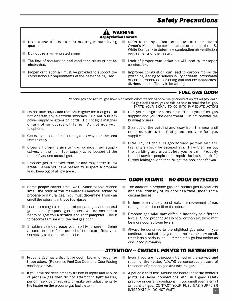
Propane gas and natural gas have man-made odorants added specifically for detection of fuel gas leaks.If a gas leak occurs, you should be able to smell the fuel gas.
THAT’S YOUR SIGNAL TO GO INTO IMMEDIATE ACTION!
■ Do not take any action that could ignite the fuel gas. Donot operate any electrical switches. Do not pull anypower supply or extension cords. Do not light matchesor any other source of f lame. Do not use yourtelephone.
■ Get everyone out of the building and away from the areaimmediately.
■ Close all propane gas tank or cylinder fuel supplyvalves, or the main fuel supply valve located at themeter if you use natural gas.
■ Propane gas is heavier than air and may settle in lowareas. When you have reason to suspect a propaneleak, keep out of all low areas.
■ Use your neighbor’s phone and call your fuel gassupplier and your fire department. Do not re-enter thebuilding or area.
■ Stay out of the building and away from the area untildeclared safe by the firefighters and your fuel gassupplier.
■ FINALLY, let the fuel gas service person and thefirefighters check for escaped gas. Have them air outthe building and area before you return. Properlytrained service people must repair the leak, check forfurther leakages, and then relight the appliance for you.
■ Some people cannot smell well. Some people cannotsmell the odor of the man-made chemical added topropane or natural gas. You must determine if you cansmell the odorant in these fuel gases.
■ Learn to recognize the odor of propane gas and naturalgas. Local propane gas dealers will be more thanhappy to give you a scratch and sniff pamphlet. Use itto become familiar with the fuel gas odor.
■ Smoking can decrease your ability to smell. Beingaround an odor for a period of time can affect yoursensitivity to that particular odor.
■ The odorant in propane gas and natural gas is colorlessand the intensity of its odor can fade under somecircumstances.
■ If there is an underground leak, the movement of gasthrough the soil can filter the odorant.
■ Propane gas odor may differ in intensity at differentlevels. Since propane gas is heavier than air, there maybe more odor at lower levels.
■ Always be sensitive to the slightest gas odor. If youcontinue to detect any gas odor, no matter how small,treat it as a serious leak. Immediately go into action asdiscussed previously.
5
Safety Precautions
FUEL GAS ODOR
ODOR FADING -- NO ODOR DETECTED
ATTENTION -- CRITICAL POINTS TO REMEMBER!
■ Propane gas has a distinctive odor. Learn to recognizethese odors. (Reference Fuel Gas Odor and Odor Fadingsections above.
■ If you have not been properly trained in repair and serviceof propane gas then do not attempt to light heater,perform service or repairs, or make any adjustments tothe heater on the propane gas fuel system.
■ Even if you are not properly trained in the service andrepair of the heater, ALWAYS be consciously aware ofthe odors of propane gas and natural gas.
■ A periodic sniff test around the heater or at the heater’sjoints; i.e. hose, connections, etc., is a good safetypractice under any conditions. If you smell even a smallamount of gas, CONTACT YOUR FUEL GAS SUPPLIERIMMEDIATELY. DO NOT WAIT!
WARNING
■ Do not use this heater for heating human livingquarters.
■ Do not use in unventilated areas.
■ The flow of combustion and ventilation air must not beobstructed.
■ Proper ventilation air must be provided to support thecombustion air requirements of the heater being used.
■ Refer to the specification section of the heater’sOwner’s Manual, heater dataplate, or contact the L.B.White Company to determine combustion air ventilationrequirements of the heater.
■ Lack of proper ventilation air will lead to impropercombustion.
■ Improper combustion can lead to carbon monoxidepoisoning leading to serious injury or death. Symptomsof carbon monoxide poisoning can include headaches,dizziness and difficulty in breathing.
Asphyxiation Hazard
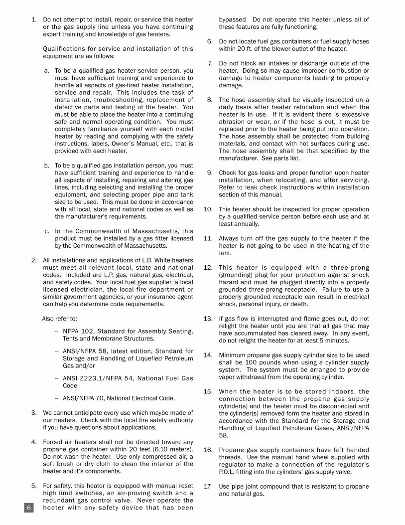
1. Do not attempt to install, repair, or service this heateror the gas supply line unless you have continuingexpert training and knowledge of gas heaters.
Qualifications for service and installation of thisequipment are as follows:
a. To be a qualified gas heater service person, youmust have sufficient training and experience tohandle all aspects of gas-fired heater installation,service and repair. This includes the task ofinstallation, troubleshooting, replacement ofdefective parts and testing of the heater. Youmust be able to place the heater into a continuingsafe and normal operating condition. You mustcompletely familiarize yourself with each modelheater by reading and complying with the safetyinstructions, labels, Owner’s Manual, etc., that isprovided with each heater.
b. To be a qualified gas installation person, you musthave sufficient training and experience to handleall aspects of installing, repairing and altering gaslines, including selecting and installing the properequipment, and selecting proper pipe and tanksize to be used. This must be done in accordancewith all local, state and national codes as well asthe manufacturer’s requirements.
c. In the Commonwealth of Massachusetts, thisproduct must be installed by a gas fitter licensedby the Commonwealth of Massachusetts.
2. All installations and applications of L.B. White heatersmust meet all relevant local, state and nationalcodes. Included are L.P. gas, natural gas, electrical,and safety codes. Your local fuel gas supplier, a locallicensed electrician, the local fire department orsimilar government agencies, or your insurance agentcan help you determine code requirements.
Also refer to:
-- NFPA 102, Standard for Assembly Seating,Tents and Membrane Structures.
-- ANSI/NFPA 58, latest edition, Standard forStorage and Handling of Liquefied PetroleumGas and/or
-- ANSI Z223.1/NFPA 54, National Fuel GasCode
-- ANSI/NFPA 70, National Electrical Code.
3. We cannot anticipate every use which maybe made ofour heaters. Check with the local fire safety authorityif you have questions about applications.
4. Forced air heaters shall not be directed toward anypropane gas container within 20 feet (6.10 meters).Do not wash the heater. Use only compressed air, asoft brush or dry cloth to clean the interior of theheater and it’s components.
5. For safety, this heater is equipped with manual resethigh limit switches, an air-proving switch and aredundant gas control valve. Never operate theheater with any safety device that has been
bypassed. Do not operate this heater unless all ofthese features are fully functioning.
6. Do not locate fuel gas containers or fuel supply hoseswithin 20 ft. of the blower outlet of the heater.
7. Do not block air intakes or discharge outlets of theheater. Doing so may cause improper combustion ordamage to heater components leading to propertydamage.
8. The hose assembly shall be visually inspected on adaily basis after heater relocation and when theheater is in use. If it is evident there is excessiveabrasion or wear, or if the hose is cut, it must bereplaced prior to the heater being put into operation.The hose assembly shall be protected from buildingmaterials, and contact with hot surfaces during use.The hose assembly shall be that specified by themanufacturer. See parts list.
9. Check for gas leaks and proper function upon heaterinstallation, when relocating, and after servicing.Refer to leak check instructions within installationsection of this manual.
10. This heater should be inspected for proper operationby a qualified service person before each use and atleast annually.
11. Always turn off the gas supply to the heater if theheater is not going to be used in the heating of thetent.
12. This heater is equipped with a three-prong(grounding) plug for your protection against shockhazard and must be plugged directly into a properlygrounded three-prong receptacle. Failure to use aproperly grounded receptacle can result in electricalshock, personal injury, or death.
13. If gas flow is interrupted and flame goes out, do notrelight the heater until you are that all gas that mayhave accummulated has cleared away. In any event,do not relight the heater for at least 5 minutes.
14. Minimum propane gas supply cylinder size to be usedshall be 100 pounds when using a cylinder supplysystem. The system must be arranged to providevapor withdrawal from the operating cylinder.
15. When the heater is to be stored indoors, theconnection between the propane gas supplycylinder(s) and the heater must be disconnected andthe cylinder(s) removed form the heater and stored inaccordance with the Standard for the Storage andHandling of Liquified Petroleum Gases, ANSI/NFPA58.
16. Propane gas supply containers have left handedthreads. Use the manual hand wheel supplied withregulator to make a connection of the regulator’sP.O.L. fitting into the cylinders’ gas supply valve.
17 Use pipe joint compound that is resistant to propaneand natural gas.
6
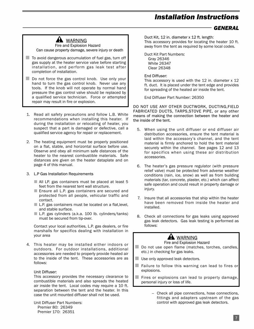
1. Read all safety precautions and follow L.B. Whiterecommendations when installing this heater. Ifduring the installation or relocating of heater, yoususpect that a part is damaged or defective, call aqualified service agency for repair or replacement.
2. The heating equipment must be properly positionedon a flat, stable, and horizontal surface before use.Observe and obey all minimum safe distances of theheater to the nearest combustible materials. Safedistances are given on the heater dataplate and onpage 4 of this manual.
3. L.P Gas Installation Requirements
■ All LP. gas containers must be placed at least 5feet from the nearest tent wall structure.
■ Ensure all L.P. gas containers are secured andprotected from all people, vehicular traffic andcontact.
■ L.P. gas containers must be located on a flat,level,and stable surface.
■ L.P. gas cylinders (a.k.a. 100 lb. cylinders/tanks)must be secured from tip-over.
Contact your local authorities, L.P. gas dealers, or firemarshalls for specifics dealing with installation inyour area
4. This heater may be installed either indoors oroutdoors. For outdoor installations, additionalaccessories are needed to properly provide heated airto the inside of the tent. These accessories are asfollows:
Unit Diffuser:This accessory provides the necessary clearance tocombustible materials and also spreads the heatedair inside the tent. Local codes may require a 10 ft.separation between the tent and the heater. In thiscase the unit mounted diffuser shall not be used.
Unit Diffuser Part Numbers:Premier 80: 26349Premier 170: 26351
Duct Kit, 12 in. diameter x 12 ft. length:This accessory provides for locating the heater 10 ft.away from the tent as required by some local codes.
Duct Kit Part Numbers:Gray 26346White 26347Clear 26348
End Diffuser:This accessory is used with the 12 in. diameter x 12ft. duct. It is placed under the tent edge and providesfor spreading of the heated air inside the tent.
End Diffuser Part Number: 26350
DO NOT USE ANY OTHER DUCTWORK, DUCTING,FIELDFABRICATED DUCTS, TARPS,STOVE PIPE, or any othermeans of making the connection between the heater andthe inside of the tent.
5. When using the unit diffuser or end diffuser airdistribution accessories, ensure the tent material islaid within the accessory’s channel, and the tentmaterial is firmly anchored to hold the tent materialsecurely within the channel. See pages 12 and 13for specifics when using these air distributionaccessories.
6. The heater’s gas pressure regulator (with pressurerelief valve) must be protected from adverse weatherconditions (rain, ice, snow) as well as from buildingmaterials (tar, concrete, plaster, etc.) which can affectsafe operation and could result in property damage orinjury.
7. Insure that all accessories that ship within the heaterhave been removed from inside the heater andinstalled.
8. Check all connections for gas leaks using approvedgas leak detectors. Gas leak testing is performed asfollows:
-- Check all pipe connections, hose connections,fittings and adapters upstream of the gascontrol with approved gas leak detectors.
WARNINGFire and Explosion Hazard
Can cause property damage, severe injury or death
■ To avoid dangerous accumulation of fuel gas, turn offgas supply at the heater service valve before startinginstal lation, and per form gas leak test af tercompletion of installation.
■ Do not force the gas control knob. Use only yourhand to turn the gas control knob. Never use anytools. If the knob will not operate by normal handpressure the gas control valve should be replaced bya qualified service technician. Force or attemptedrepair may result in fire or explosion.
7
Installation Instructions
GENERAL
WARNINGFire and Explosion Hazard
■ Do not use open flame (matches, torches, candles,etc.) in checking for gas leaks.
■ Use only approved leak detectors.
■ Failure to follow this warning can lead to fires orexplosions.
■ Fires or explosions can lead to property damage,personal injury or loss of life.
-- In the event a gas leak is detected, check thecomponents involved for cleanliness andproper application of pipe compound beforefurther tightening.
-- Tighten the gas connections as necessary tostop the leak.
-- After all connections are checked and anyleaks are stopped, turn on the main burner.
-- Stand clear while the main burner ignites toprevent injury caused from hidden leaks thatcould cause flashback.
-- With the main burner in operation, check allconnections, hose connections, fittings andjoints as well as the gas control valve inlet andoutlet connections with approved gas leakdetectors.
-- If a leak is detected, check the componentsinvolved for cleanliness in the thread areasand proper application of pipe compoundbefore further tightening.
-- Tighten the gas connection as necessary tostop the leak.
-- If necessary, replace the parts or componentsinvolved if the leak cannot be stopped.
-- Ensure all gas leaks have been identified andrepaired before proceeding.
9. A qualified service agency must check for properoperating gas pressure upon installation of theheater.
10. Light according to instructions on heater or withinowner's manual.
11. The heater must have the proper gas regulator for theapplication. Use only the L.B. White regulatororiginally supplied with the heater. This regulatorincludes a POL fitting incorporating an excess flowvalve. The excess flow valve is a safety device whichprotects against discharge from the propane gassupply container if the regulator is broken off. If thePOL fitting is ever replaced, it needs to be replacedwith an L.B. White POL fitting. Failure to do so canresult in fires, explosions, loss of property, injury ordeath.
12. The regulator must be connected to the gas supply sothat gas pressure at the inlet to the gas valve isregulated within the range specified on the dataplateat all times. Contact your gas supplier, or theL.B. White Co., Inc. if you have any questions.
13. This heater is configured for use for propane gasvapor withdrawal only. Do not use the heater in anpropane gas liquid withdrawal system or application.If you are in doubt, contact the L.B. White Co., Inc.
14. The heater must be installed so as not to interferewith or obstruct normal exits, emergency exits, doorsand walkways.
15. Railing, fencing or suitable substitute materials mustbe used to keep the heating equipment from anypeople using and visiting the structure.
16. The heater shall be located so that rain, ice, or snowdrainage from the structure does not affect heateroperation. If the heater is located outside, it must belocated above any pooled or standing water. Asurrounding trench is recommended to drain any rain,ice or snow away from the unit.
17. The ground and surrounding terrain must be clearedof any combustible vegetation and other combustiblematerials when the heater is mounted outside.
18. Eventually, like all electrical/mechanical devices, thethermostat can fail. Thermostat failure may result inan underheating condition. The thermostat should betested to make sure it turns the heater on and offwithin a temperature differential of ±3°F.
19. Take time to understand how to operate and maintainthe heater by using this Owner’s Manual. Make sureyou know how to shut off the gas supply to thebuilding and also to the individual heater. Contactyour fuel gas supplier if you have any questions.
20. Any defects found in performing any of the service ormaintenance procedures must be eliminated anddefective parts replaced immediately. The heatermust be retested by properly qualified servicepersonnel before placing the heater back into use.
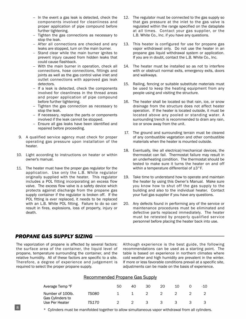
The vaporization of propane is affected by several factors:the surface area of the container, the liquid level ofpropane, temperature surrounding the container, and therelative humidity. All of these factors are specific to a site.Therefore, a degree of experience and judgement isrequired to select the proper propane supply.
Although experience is the best guide, the followingrecommendations can be used as a starting point. Thetable is based on experience in northern climates wherecold weather and high humidity are prevalent in the winter.If more or less favorable conditions prevail at a specific site,adjustments can be made on the basis of experience.
PROPANE GAS SUPPLY SIZING
Recommended Propane Gas Supply
Average Temp ºF 50 40 30 20 10 0 -10
Number of 100lb. TS080 1 1 2 2 2 2 2Gas Cylinders to Use Per Heater TS170 2 2 3 3 3 3 3
* Cylinders must be manifolded together to allow simultaneous vapor withdrawal from all cylinders.8
HANDLE BRACKET
EXTEND HANDLE
UNTIL IT SNAPS INTO
RETAINING HOLE
RETAINING HOLE
AT UNDERSIDE
SNAP BUTTON
AT UNDERSIDE
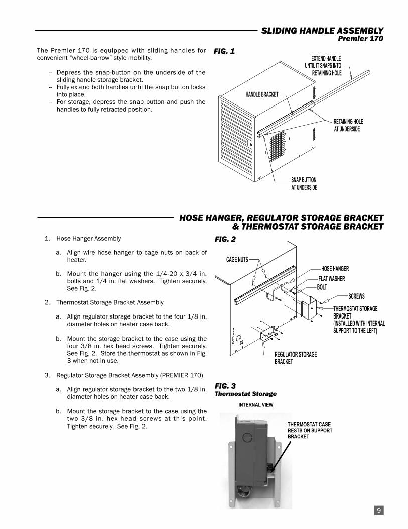
The Premier 170 is equipped with sliding handles forconvenient “wheel-barrow” style mobility.
-- Depress the snap-button on the underside of thesliding handle storage bracket.
-- Fully extend both handles until the snap button locksinto place.
-- For storage, depress the snap button and push thehandles to fully retracted position.
FIG. 1
SLIDING HANDLE ASSEMBLYPremier 170
TS170G-02
REGULATOR STORAGEBRACKET
CAGE NUTSHOSE HANGER
FLAT WASHERBOLT
THERMOSTAT STORAGEBRACKET (INSTALLED WITH INTERNAL SUPPORT TO THE LEFT)
SCREWS
1. Hose Hanger Assembly
a. Align wire hose hanger to cage nuts on back ofheater.
b. Mount the hanger using the 1/4-20 x 3/4 in.bolts and 1/4 in. flat washers. Tighten securely.See Fig. 2.
2. Thermostat Storage Bracket Assembly
a. Align regulator storage bracket to the four 1/8 in.diameter holes on heater case back.
b. Mount the storage bracket to the case using thefour 3/8 in. hex head screws. Tighten securely.See Fig. 2. Store the thermostat as shown in Fig.3 when not in use.
3. Regulator Storage Bracket Assembly (PREMIER 170)
a. Align regulator storage bracket to the two 1/8 in.diameter holes on heater case back.
b. Mount the storage bracket to the case using thetwo 3/8 in. hex head screws at this point.Tighten securely. See Fig. 2.
FIG. 2
FIG. 3Thermostat Storage
HOSE HANGER, REGULATOR STORAGE BRACKET& THERMOSTAT STORAGE BRACKET
9
THERMOSTAT CASERESTS ON SUPPORTBRACKET
INTERNAL VIEW
10
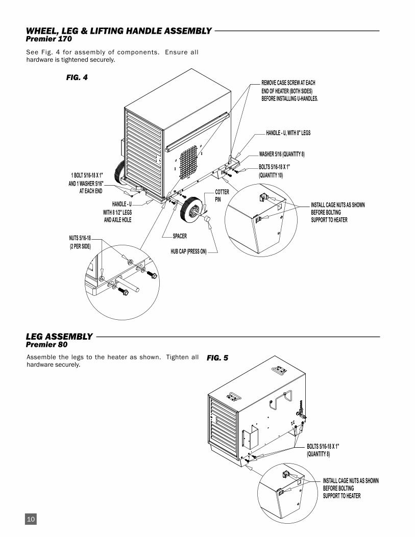
SPACER
WASHER 5/16 (QUANTITY 8)
HANDLE - U, WITH 8" LEGS
HUB CAP (PRESS ON)
NUTS 5/16-18(2 PER SIDE)
INSTALL CAGE NUTS AS SHOWNBEFORE BOLTINGSUPPORT TO HEATER
REMOVE CASE SCREW AT EACHEND OF HEATER (BOTH SIDES)BEFORE INSTALLING U-HANDLES.
HANDLE - UWITH 8 1/2" LEGS AND AXLE HOLE
1 BOLT 5/16-18 X 1"AND 1 WASHER 5/16" AT EACH END
BOLTS 5/16-18 X 1"(QUANTITY 10)
COTTERPIN
See Fig. 4 for assembly of components. Ensure allhardware is tightened securely.
WHEEL, LEG & LIFTING HANDLE ASSEMBLYPremier 170
TS080G-01
INSTALL CAGE NUTS AS SHOWNBEFORE BOLTING SUPPORT TO HEATER
BOLTS 5/16-18 X 1"(QUANTITY 8)
Assemble the legs to the heater as shown. Tighten allhardware securely.
FIG. 5
LEG ASSEMBLY Premier 80
FIG. 4
11
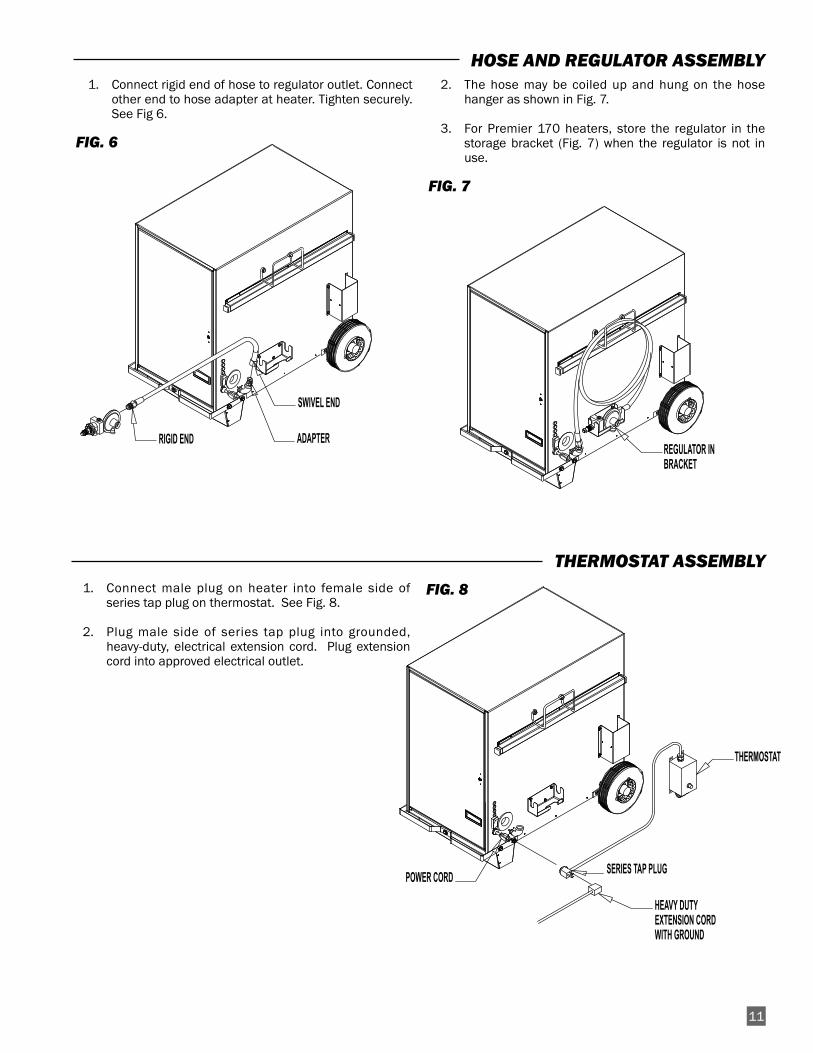
RIGID END
SWIVEL END
ADAPTER
1. Connect rigid end of hose to regulator outlet. Connectother end to hose adapter at heater. Tighten securely.See Fig 6.
FIG. 6
2. The hose may be coiled up and hung on the hosehanger as shown in Fig. 7.
3. For Premier 170 heaters, store the regulator in thestorage bracket (Fig. 7) when the regulator is not inuse.
FIG. 7
HOSE AND REGULATOR ASSEMBLY
POWER CORD
HEAVY DUTY EXTENSION CORDWITH GROUND
SERIES TAP PLUG
THERMOSTAT
1. Connect male plug on heater into female side ofseries tap plug on thermostat. See Fig. 8.
2. Plug male side of series tap plug into grounded,heavy-duty, electrical extension cord. Plug extensioncord into approved electrical outlet.
FIG. 8
THERMOSTAT ASSEMBLY
REGULATOR IN BRACKET
SIDE WALL10 FTCLEARANCE
EARLIER STYLE DUCTING
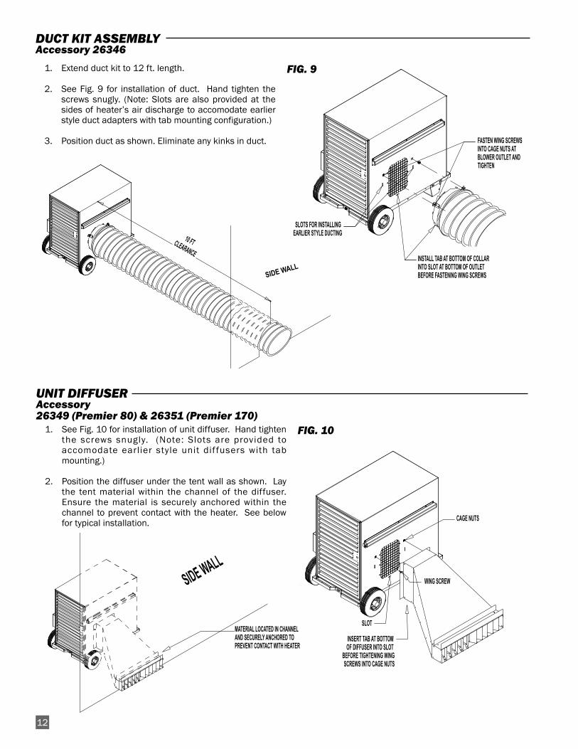
DUCT KIT ASSEMBLYAccessory 26346
CAGE NUTS
SLOT
WING SCREW
INSERT TAB AT BOTTOM OF DIFFUSER INTO SLOT
BEFORE TIGHTENING WINGSCREWS INTO CAGE NUTS
1. See Fig. 10 for installation of unit diffuser. Hand tightenthe screws snugly. (Note: Slots are provided toaccomodate earlier style unit dif fusers with tabmounting.)
2. Position the diffuser under the tent wall as shown. Laythe tent material within the channel of the diffuser.Ensure the material is securely anchored within thechannel to prevent contact with the heater. See belowfor typical installation.
FIG. 10
UNIT DIFFUSER Accessory26349 (Premier 80) & 26351 (Premier 170)
FASTEN WING SCREWSINTO CAGE NUTS ATBLOWER OUTLET ANDTIGHTEN
INSTALL TAB AT BOTTOM OF COLLARINTO SLOT AT BOTTOM OF OUTLETBEFORE FASTENING WING SCREWS
SLOTS FOR INSTALLING EARLIER STYLE DUCTING
SIDE WALL
1. Extend duct kit to 12 ft. length.
2. See Fig. 9 for installation of duct. Hand tighten thescrews snugly. (Note: Slots are also provided at thesides of heater’s air discharge to accomodate earlierstyle duct adapters with tab mounting configuration.)
3. Position duct as shown. Eliminate any kinks in duct.
FIG. 9
SIDE WALL
MATERIAL LOCATED IN CHANNEL AND SECURELY ANCHORED TO PREVENT CONTACT WITH HEATER
12
TS170G-07
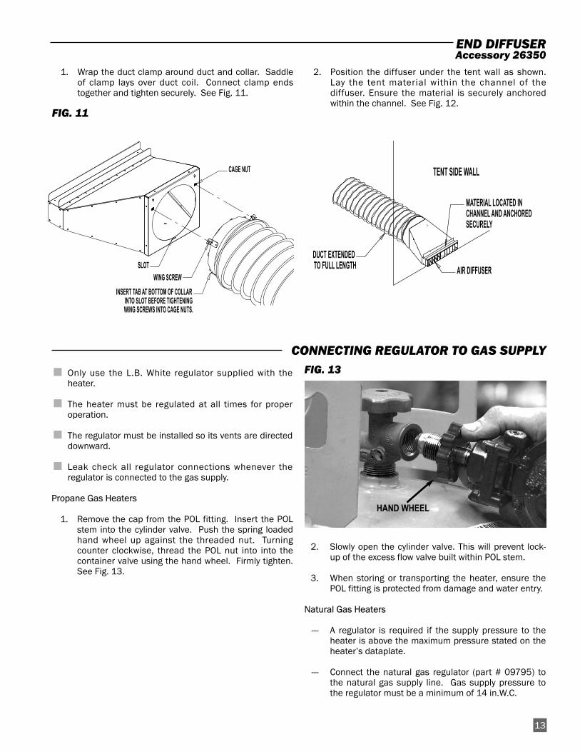
CAGE NUT
SLOTWING SCREW
INSERT TAB AT BOTTOM OF COLLARINTO SLOT BEFORE TIGHTENINGWING SCREWS INTO CAGE NUTS.
13
1. Wrap the duct clamp around duct and collar. Saddleof clamp lays over duct coil. Connect clamp endstogether and tighten securely. See Fig. 11.
FIG. 11
2. Position the diffuser under the tent wall as shown.Lay the tent material within the channel of thediffuser. Ensure the material is securely anchoredwithin the channel. See Fig. 12.
■ Only use the L.B. White regulator supplied with theheater.
■ The heater must be regulated at all times for properoperation.
■ The regulator must be installed so its vents are directeddownward.
■ Leak check all regulator connections whenever theregulator is connected to the gas supply.
Propane Gas Heaters
1. Remove the cap from the POL fitting. Insert the POLstem into the cylinder valve. Push the spring loadedhand wheel up against the threaded nut. Turningcounter clockwise, thread the POL nut into into thecontainer valve using the hand wheel. Firmly tighten.See Fig. 13.
FIG. 13
2. Slowly open the cylinder valve. This will prevent lock-up of the excess flow valve built within POL stem.
3. When storing or transporting the heater, ensure thePOL fitting is protected from damage and water entry.
Natural Gas Heaters
--- A regulator is required if the supply pressure to theheater is above the maximum pressure stated on theheater’s dataplate.
--- Connect the natural gas regulator (part # 09795) tothe natural gas supply line. Gas supply pressure tothe regulator must be a minimum of 14 in.W.C.
CONNECTING REGULATOR TO GAS SUPPLY
END DIFFUSER Accessory 26350
HAND WHEEL
DUCT EXTENDED
TO FULL LENGTH
TENT SIDE WALL
MATERIAL LOCATED IN
CHANNEL AND ANCHORED
SECURELY
AIR DIFFUSER
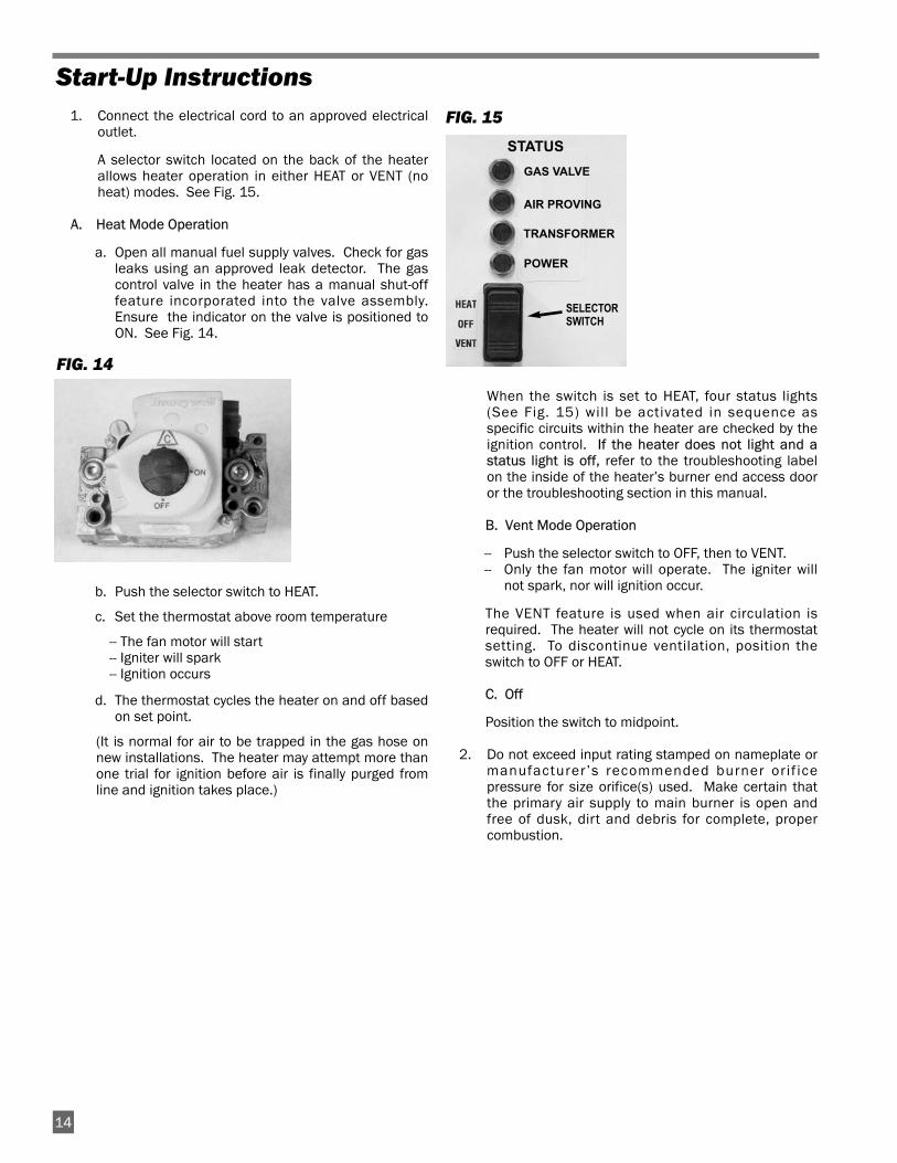
1. Connect the electrical cord to an approved electricaloutlet.
A selector switch located on the back of the heaterallows heater operation in either HEAT or VENT (noheat) modes. See Fig. 15.
A. Heat Mode Operation
a. Open all manual fuel supply valves. Check for gasleaks using an approved leak detector. The gascontrol valve in the heater has a manual shut-offfeature incorporated into the valve assembly.Ensure the indicator on the valve is positioned toON. See Fig. 14.
FIG. 14
b. Push the selector switch to HEAT.
c. Set the thermostat above room temperature
-- The fan motor will start-- Igniter will spark-- Ignition occurs
d. The thermostat cycles the heater on and off basedon set point.
(It is normal for air to be trapped in the gas hose onnew installations. The heater may attempt more thanone trial for ignition before air is finally purged fromline and ignition takes place.)
FIG. 15
When the switch is set to HEAT, four status lights(See Fig. 15) will be activated in sequence asspecific circuits within the heater are checked by theignition control. If the heater does not light and astatus light is off, refer to the troubleshooting labelon the inside of the heater’s burner end access dooror the troubleshooting section in this manual.
B. Vent Mode Operation
-- Push the selector switch to OFF, then to VENT.-- Only the fan motor will operate. The igniter will
not spark, nor will ignition occur.
The VENT feature is used when air circulation isrequired. The heater will not cycle on its thermostatsetting. To discontinue ventilation, position theswitch to OFF or HEAT.
C. Off
Position the switch to midpoint.
2. Do not exceed input rating stamped on nameplate ormanufacturer’s recommended burner orif icepressure for size orifice(s) used. Make certain thatthe primary air supply to main burner is open andfree of dusk, dirt and debris for complete, propercombustion.
Start-Up Instructions
1414
STATUS
GAS VALVE
AIR PROVING
TRANSFORMER
POWER
SELECTORSWITCH
1. The area surrounding the heater shall be kept clearand free from combustible materials, gasoline, andother flammable vapors and liquids.
2. Have your gas supplier check all gas piping annuallyfor leaks or restrictions in gas lines.
3. Regulators must be periodically inspected to makesure the regulator vents are not blocked. Debris,insects, insect nests, snow, or ice on a regulator canblock vents and cause excess pressure at the heater.
4. Regulators can wear out and function improperly.Have your gas supplier check the date codes on allregulators installed and check delivery pressures tothe heater to make sure that the regulator is reliable.
5. Check all wiring, associated terminals, and electricalcomponents within the heater for corrosion, frayed orcut insulation, tight connections, etc. Repair orreplace as necessary.
6. Review all heater markings (i.e. wiring diagram,warnings, start-up, shut-down, troubleshooting, etc.)at the time of maintenance for legibility. Make surenone are cut, torn, or otherwise damaged. Anydamaged markings must be replaced immediately bycontacting the L.B. White Co., Inc. Dataplates, start-up and shut-down instructions and warnings areavailable at no cost. A nominal charge will be appliedfor wiring diagrams.
Maintenance Instructions
1. Before cleaning, shut off all gas supply valves anddisconnect electrical supply.
2. The heater should have dir t or dust removedperiodically:
a. Before each use give the heater a generalcleaning using compressed air or a soft brush ordry rag on its case and internal components. Atthis time, dust off the motor case to prevent themotor from over-heating.
b. At least once a year, give the heater a thoroughcleaning. At this time, remove the fan and motorassembly and brush or blow off the fan bladeassembly. Additionally, make sure the burner airinlet venturi ports and the casting are free of dustaccumulation.
WARNING
Do not use a pressure washer, water, or liquid cleaningsolution on any gas controls. Use of a pressure washer,water, or l iquid cleaning solution on the controlcomponents can cause severe personal injury orproperty damage due to water and/or liquids:
■ In electrical components, and wires causing electricalshock or equipment failure.
■ On gas control valves causing corrosion which canresult in gas leaks and fire or explosion from the leak.
Clean all components of the heater with pressurized air,a dry brush, or a dry cloth.
Cleaning Instructions
WARNINGFire, Burn, and Explosion Hazard
■ This heater contains electrical and mechanical components in the gas management, and safety systems.
■ Such components may become inoperative or fail due to dust, dirt, wear and aging.
■ Periodic cleaning and inspection as well as proper maintenance are essential to avoid serious injury or propertydamage.
1415
For normal shut-down, set the thermostat below roomtemperature. When servicing or performing maintenance,follow steps 1 - 5.
1. Close the fuel supply valve.
2. Allow the heater to burn off any fuel gas remaining inthe gas supply line.
3. For heaters so equipped, set the thermostat to “Off”or “No Heat”.
4. Position selector switch to “Off.”
5. Disconnect the heater from its gas and electricalsupplies.
Shut-Down Instructions
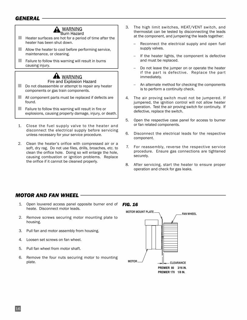
1. Open louvered access panel opposite burner end ofheate. Disconnect motor leads.
2. Remove screws securing motor mounting plate tohousing.
3. Pull fan and motor assembly from housing.
4. Loosen set screws on fan wheel.
5. Pull fan wheel from motor shaft.
6. Remove the four nuts securing motor to mountingplate.
FIG. 16
16
MOTOR MOUNT PLATEFAN WHEEL
MOTOR CLEARANCE
PREMIER 80 3/16 IN.PREMIER 170 1/8 IN.
MOTOR AND FAN WHEEL
1. Close the fuel supply valve to the heater anddisconnect the electrical supply before servicingunless necessary for your service procedure.
2. Clean the heater’s orifice with compressed air or asoft, dry rag. Do not use files, drills, broaches, etc. toclean the orifice hole. Doing so will enlarge the hole,causing combustion or ignition problems. Replacethe orifice if it cannot be cleaned properly.
3. The high limit switches, HEAT/VENT switch, andthermostat can be tested by disconnecting the leadsat the component, and jumpering the leads together:
-- Reconnect the electrical supply and open fuelsupply valves.
-- If the heater lights, the component is defectiveand must be replaced.
-- Do not leave the jumper on or operate the heaterif the par t is defective. Replace the par timmediately.
-- An alternate method for checking the componentsis to perform a continuity check.
4. The air proving switch must not be jumpered. Ifjumpered, the ignition control will not allow heateroperation. Test the air proving switch for continuity. Ifdefective, replace the switch.
5. Open the respective case panel for access to burneror fan related components.
6. Disconnect the electrical leads for the respectivecomponent.
7. For reassembly, reverse the respective serviceprocedure. Ensure gas connections are tightenedsecurely.
8. After servicing, start the heater to ensure properoperation and check for gas leaks.
WARNINGBurn Hazard
■ Heater surfaces are hot for a period of time after theheater has been shut down.
■ Allow the heater to cool before performing service,maintenance, or cleaning.
■ Failure to follow this warning will result in burnscausing injury.
WARNINGFire and Explosion Hazard
■ Do not disassemble or attempt to repair any heatercomponents or gas train components.
■ All component parts must be replaced if defects arefound.
■ Failure to follow this warning will result in fire orexplosions, causing property damage, injury, or death.
GENERAL
IGNITER AND FLAME SENSOR ASSEMBLY
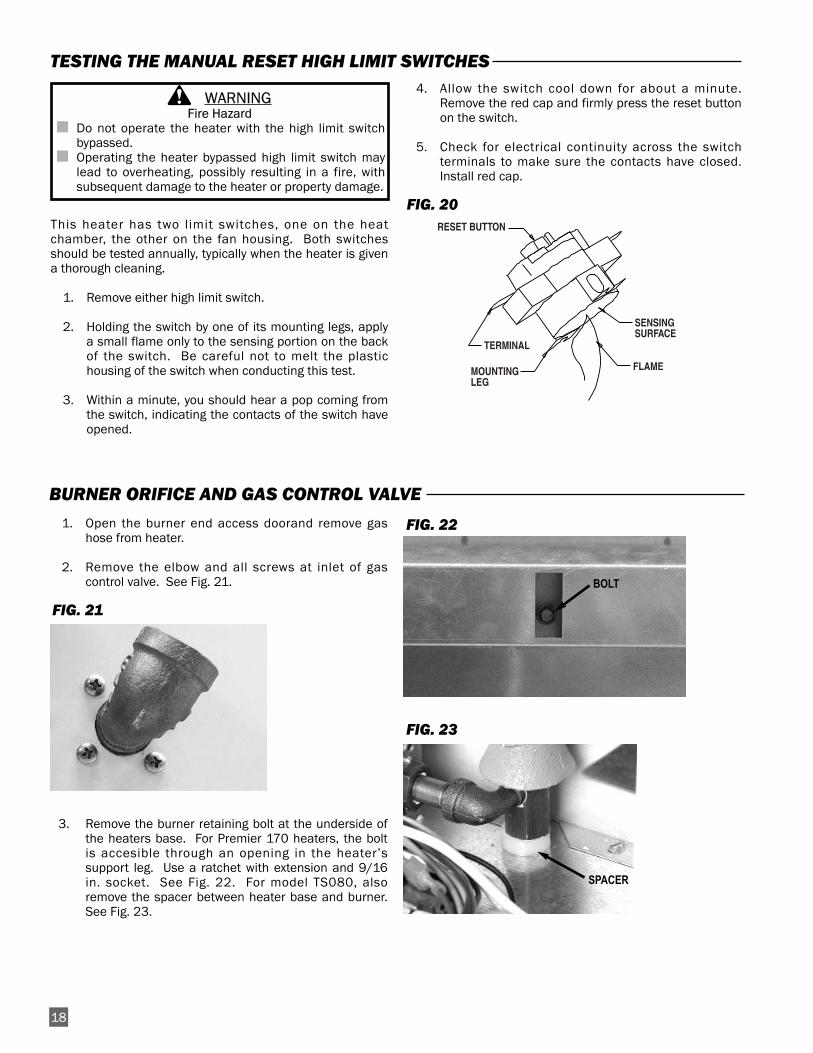
1. See Fig. 18 or 19, depending on heater model, forlocation of igniter/sensor assembly.
2. Remove the two screws securing the mountingbracket to the burner. Remove igniter assembly.
3. Disconnect high voltage cable from igniter assembly.
4. Remove the two screws that secure the igniter sensorto the mounting bracket.
■ The igniter and ground rod should be cleaned tomaintain proper ignition.
-- Use steel wool or emery cloth.-- Rub briskly to remove buildup of dust, dirt, and
oxide.
■ Check the igniter’s ceramic base for cracks.
-- Replace the igniter if cracks are found.
17
1/2 IN. DISTANCE FROM IGNITER TOP TO BURNER TOP
MOUNTING BRACKET
IGNITER BRACKET MOUNTING SCREWS
IGNITER/SENSOR MOUNTING SCREWS
HIGH VOLTAGE IGNITION LEAD
ELECTRODE GAP IS 1/8" &CENTERED OVER BURNER PORT
BURNER PORT
TOP VIEWFRONT VIEWFIG. 18
Premier 170
FRONT VIEW TOP VIEW
MOUNTING BRACKET
1 1/2 IN. DISTANCE FROM IGNITER TO "V" OF BURNER CASTING
IGNITER BRACKETMOUNTING SCREWS
IGNITER/SENSORMOUNTING SCREWS
ELECTRODE GAP IS1/8" & CENTEREDOVER BURNER PORT
BURNER PORT
FIG. 19
Premier 80
AIR PROVING SWITCH
SWITCH W/ PADDLE
LEADS
NUTS
PADDLE
OBLONG HOLE
HOUSING SIDE PANEL
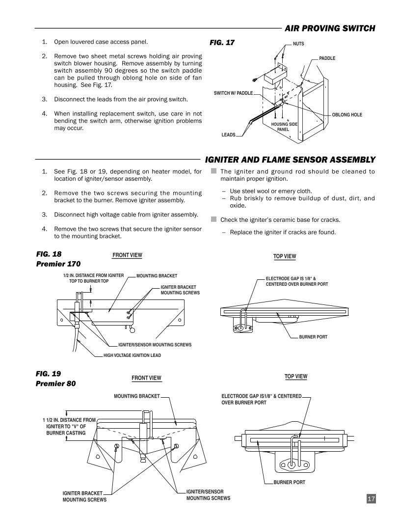
1. Open louvered case access panel.
2. Remove two sheet metal screws holding air provingswitch blower housing. Remove assembly by turningswitch assembly 90 degrees so the switch paddlecan be pulled through oblong hole on side of fanhousing. See Fig. 17.
3. Disconnect the leads from the air proving switch.
4. When installing replacement switch, use care in notbending the switch arm, otherwise ignition problemsmay occur.
FIG. 17
1. Open the burner end access doorand remove gashose from heater.
2. Remove the elbow and all screws at inlet of gascontrol valve. See Fig. 21.
FIG. 21
3. Remove the burner retaining bolt at the underside ofthe heaters base. For Premier 170 heaters, the boltis accesible through an opening in the heater’ssupport leg. Use a ratchet with extension and 9/16in. socket. See Fig. 22. For model TS080, alsoremove the spacer between heater base and burner.See Fig. 23.
FIG. 22
FIG. 23
This heater has two limit switches, one on the heatchamber, the other on the fan housing. Both switchesshould be tested annually, typically when the heater is givena thorough cleaning.
1. Remove either high limit switch.
2. Holding the switch by one of its mounting legs, applya small flame only to the sensing portion on the backof the switch. Be careful not to melt the plastichousing of the switch when conducting this test.
3. Within a minute, you should hear a pop coming fromthe switch, indicating the contacts of the switch haveopened.
4. Allow the switch cool down for about a minute.Remove the red cap and firmly press the reset buttonon the switch.
5. Check for electrical continuity across the switchterminals to make sure the contacts have closed.Install red cap.
FIG. 20
18
TESTING THE MANUAL RESET HIGH LIMIT SWITCHES
WARNINGFire Hazard
■ Do not operate the heater with the high limit switchbypassed.
■ Operating the heater bypassed high limit switch maylead to overheating, possibly resulting in a fire, withsubsequent damage to the heater or property damage.
RESET BUTTON
SENSINGSURFACE
TERMINAL
FLAMEMOUNTINGLEG
BURNER ORIFICE AND GAS CONTROL VALVE
SPACER
BOLT
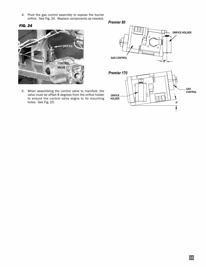
4. Pivot the gas control assembly to expose the burnerorifice. See Fig. 24. Replace components as needed.
FIG. 24
5. When assembling the control valve to manifold, thevalve must be offset 8 degrees from the orifice holderto ensure the control valve aligns to its mountingholes. See Fig. 25.
8°
19
ORIFICE HOLDER
BYNAME/JIMI/TS170B/TS170-02
ORIFICEHOLDER
GASCONTROL
8°
Premier 80
Premier 170
GAS CONTROL
ORIFICE
CONTROLVALVE
ON
OFF
LOW PRESSURE GUAGE
OUTLET PRESSURE TAP
INLET PRESSURE TAP
LOW PRESSURE GUAGE
EXAMPLE SHOWS PRESSURE FOR L P GAS
OFF
ON
INTERNAL PRESSURE REGULATOR
ATTENTION
■ The following explains a typical procedure to be followedin checking gas pressures.
■ The gas pressures will vary depending upon fuel type.
■ Consult the dataplate on the heater or page 4 in thismanual for specific pressures to be used in conjunctionwith this procedure.
■ Gas pressure measured at the inlet to the gas valve isInlet Pressure and gas pressure measured at the outletof the gas valve is Burner Manifold Pressure.
A. Preparation
1. Obtain two pressure gauges capable of reading up to35 in. W.C.
2. Disconnect the heater from the electrical supply andclose the fuel supply valve to the heater inlet.
3. Open the burner access panel.
4. Brush or blow off any dust and dirt on or in the vicinityof the gas control valve.
B. Gauge Installation
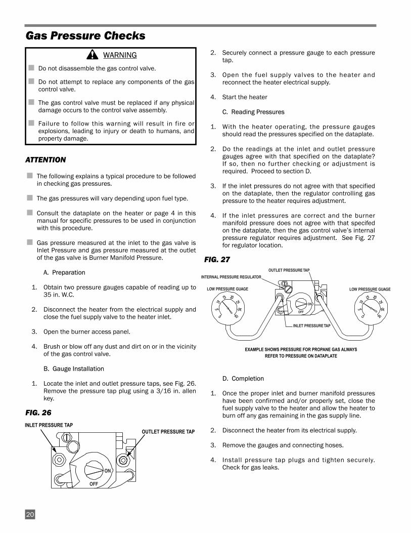
1. Locate the inlet and outlet pressure taps, see Fig. 26.Remove the pressure tap plug using a 3/16 in. allenkey.
FIG. 26
2. Securely connect a pressure gauge to each pressuretap.
3. Open the fuel supply valves to the heater andreconnect the heater electrical supply.
4. Start the heater
C. Reading Pressures
1. With the heater operating, the pressure gaugesshould read the pressures specified on the dataplate.
2. Do the readings at the inlet and outlet pressuregauges agree with that specified on the dataplate?If so, then no further checking or adjustment isrequired. Proceed to section D.
3. If the inlet pressures do not agree with that specifiedon the dataplate, then the regulator controlling gaspressure to the heater requires adjustment.
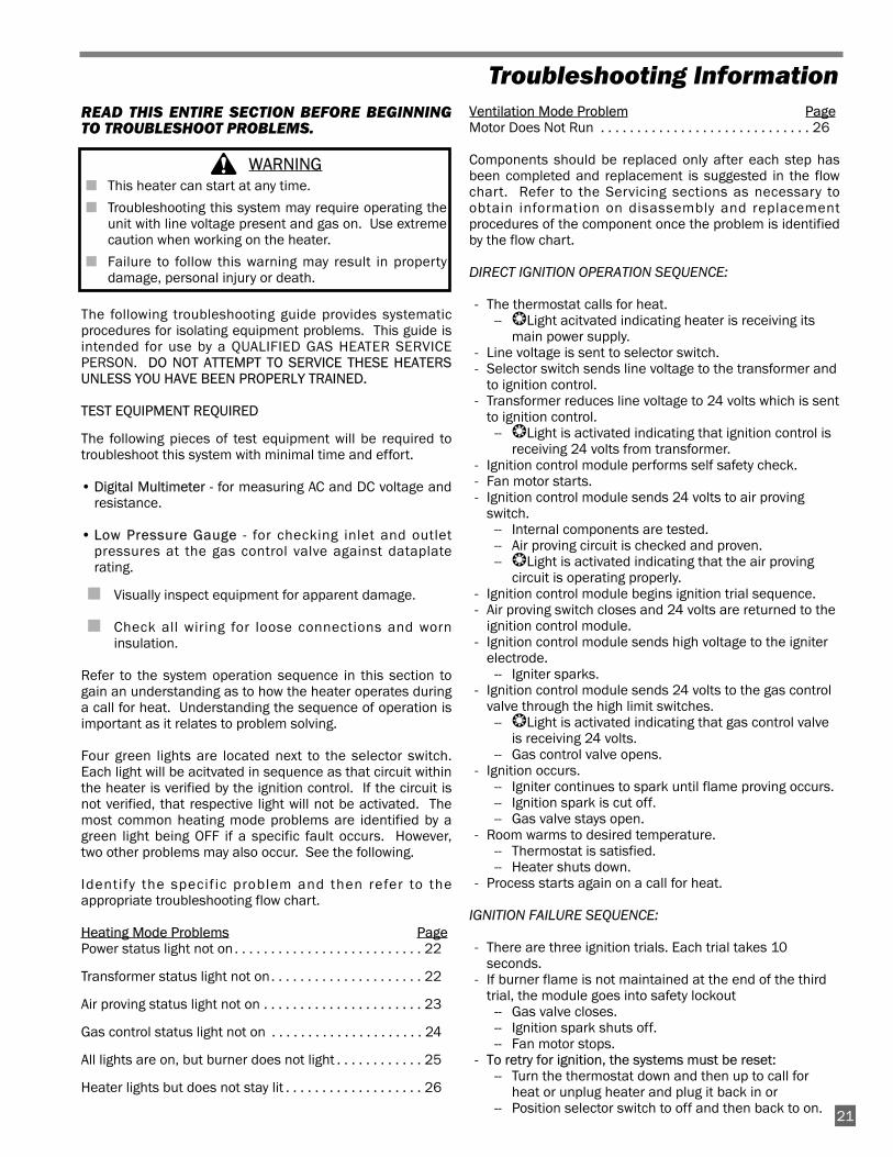
4. If the inlet pressures are correct and the burnermanifold pressure does not agree with that specifedon the dataplate, then the gas control valve’s internalpressure regulator requires adjustment. See Fig. 27for regulator location.
FIG. 27
D. Completion
1. Once the proper inlet and burner manifold pressureshave been confirmed and/or properly set, close thefuel supply valve to the heater and allow the heater toburn off any gas remaining in the gas supply line.
2. Disconnect the heater from its electrical supply.
3. Remove the gauges and connecting hoses.
4. Install pressure tap plugs and tighten securely.Check for gas leaks.
Gas Pressure Checks
WARNING
■ Do not disassemble the gas control valve.
■ Do not attempt to replace any components of the gascontrol valve.
■ The gas control valve must be replaced if any physicaldamage occurs to the control valve assembly.
■ Failure to follow this warning will result in fire orexplosions, leading to injury or death to humans, andproperty damage.
20
EXAMPLE SHOWS PRESSURE FOR PROPANE GAS ALWAYSREFER TO PRESSURE ON DATAPLATE
OUTLET PRESSURE TAPINLET PRESSURE TAP
READ THIS ENTIRE SECTION BEFORE BEGINNINGTO TROUBLESHOOT PROBLEMS.
The following troubleshooting guide provides systematicprocedures for isolating equipment problems. This guide isintended for use by a QUALIFIED GAS HEATER SERVICEPERSON. DO NOT ATTEMPT TO SERVICE THESE HEATERSUNLESS YOU HAVE BEEN PROPERLY TRAINED.
TEST EQUIPMENT REQUIRED
The following pieces of test equipment will be required totroubleshoot this system with minimal time and effort.
• Digital Multimeter - for measuring AC and DC voltage andresistance.
• Low Pressure Gauge - for checking inlet and outletpressures at the gas control valve against dataplaterating.
■ Visually inspect equipment for apparent damage.
■ Check all wiring for loose connections and worninsulation.
Refer to the system operation sequence in this section togain an understanding as to how the heater operates duringa call for heat. Understanding the sequence of operation isimportant as it relates to problem solving.
Four green lights are located next to the selector switch.Each light will be acitvated in sequence as that circuit withinthe heater is verified by the ignition control. If the circuit isnot verified, that respective light will not be activated. Themost common heating mode problems are identified by agreen light being OFF if a specific fault occurs. However,two other problems may also occur. See the following.
Identify the specif ic problem and then refer to theappropriate troubleshooting flow chart.
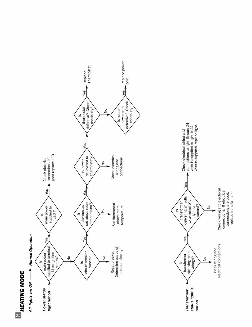
Heating Mode Problems PagePower status light not on . . . . . . . . . . . . . . . . . . . . . . . . . . 22
Transformer status light not on. . . . . . . . . . . . . . . . . . . . . 22
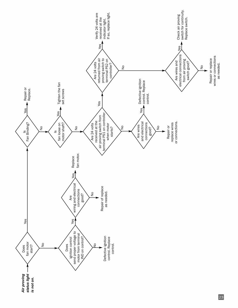
Air proving status light not on . . . . . . . . . . . . . . . . . . . . . . 23
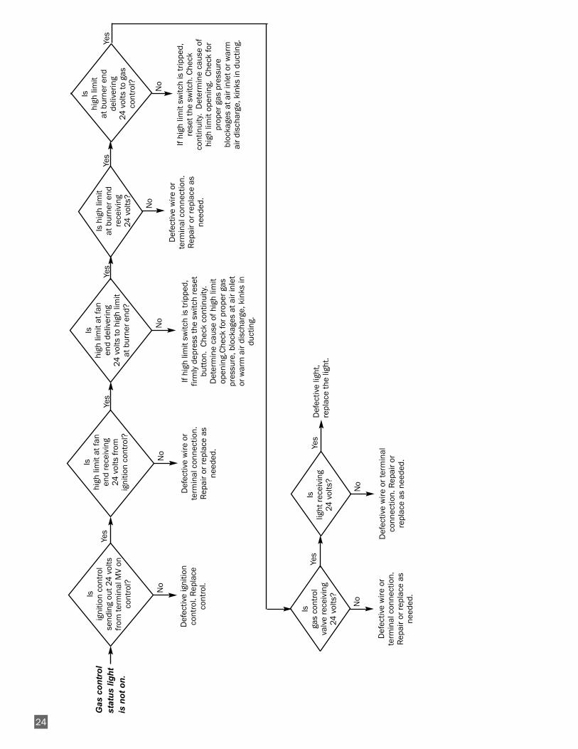
Gas control status light not on . . . . . . . . . . . . . . . . . . . . . 24
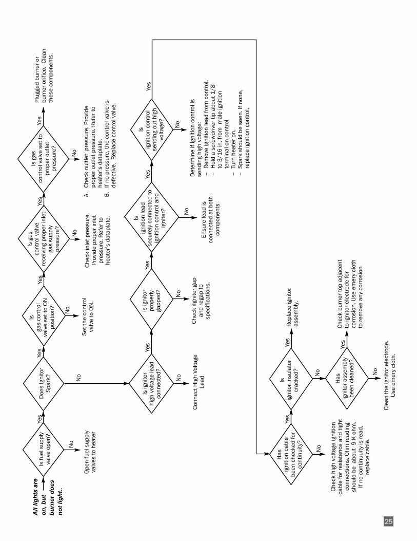
All lights are on, but burner does not light . . . . . . . . . . . . 25
Heater lights but does not stay lit . . . . . . . . . . . . . . . . . . . 26
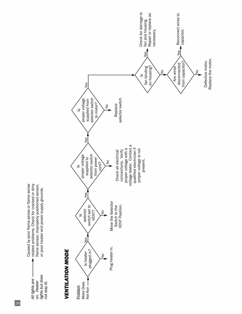
Ventilation Mode Problem PageMotor Does Not Run . . . . . . . . . . . . . . . . . . . . . . . . . . . . . 26
Components should be replaced only after each step hasbeen completed and replacement is suggested in the flowchart. Refer to the Servicing sections as necessary toobtain information on disassembly and replacementprocedures of the component once the problem is identifiedby the flow chart.
DIRECT IGNITION OPERATION SEQUENCE:
- The thermostat calls for heat.-- ❂Light acitvated indicating heater is receiving its
main power supply.- Line voltage is sent to selector switch.- Selector switch sends line voltage to the transformer and
to ignition control.- Transformer reduces line voltage to 24 volts which is sent
to ignition control.-- ❂Light is activated indicating that ignition control is
receiving 24 volts from transformer. - Ignition control module performs self safety check.- Fan motor starts.- Ignition control module sends 24 volts to air proving
switch.-- Internal components are tested.-- Air proving circuit is checked and proven.-- ❂Light is activated indicating that the air proving
circuit is operating properly.- Ignition control module begins ignition trial sequence.- Air proving switch closes and 24 volts are returned to the
ignition control module.- Ignition control module sends high voltage to the igniter
electrode.-- Igniter sparks.
- Ignition control module sends 24 volts to the gas controlvalve through the high limit switches.
-- ❂Light is activated indicating that gas control valveis receiving 24 volts.
-- Gas control valve opens.- Ignition occurs.
-- Igniter continues to spark until flame proving occurs.-- Ignition spark is cut off.-- Gas valve stays open.
- Room warms to desired temperature.-- Thermostat is satisfied.-- Heater shuts down.
- Process starts again on a call for heat.
IGNITION FAILURE SEQUENCE:
- There are three ignition trials. Each trial takes 10seconds.
- If burner flame is not maintained at the end of the thirdtrial, the module goes into safety lockout
-- Gas valve closes.-- Ignition spark shuts off.-- Fan motor stops.
- To retry for ignition, the systems must be reset:-- Turn the thermostat down and then up to call for
heat or unplug heater and plug it back in or-- Position selector switch to off and then back to on.
WARNING■ This heater can start at any time.
■ Troubleshooting this system may require operating theunit with line voltage present and gas on. Use extremecaution when working on the heater.
■ Failure to follow this warning may result in propertydamage, personal injury or death.
21
Troubleshooting Information
All
ligh
ts a
re O
N
Pow
er s
tatu
slig
ht n
ot o
n
Nor
mal
Ope
ratio
n
HE
AT
ING
MO
DE
22
Is
circ
uit b
reak
er
clos
ed?
Res
et b
reak
er.
Det
erm
ine
casu
e of
brea
ker t
rippi
ng
No
Is
ther
mos
tat
set a
bove
room
tem
pera
ture
?
Set t
herm
osta
tab
ove
room
tem
pera
ture
.
No
Yes
Yes
Is p
ower
de
lieve
red
toth
erm
osta
t?
Rep
lace
Ther
mos
tat.
No
Yes
Is
ther
mos
tat
defe
ctiv
e? C
heck
co
ntin
uity
?
No
Chec
k el
ectr
ical
wiri
ng a
ndco
nnec
tions
Yes
Is h
eate
r po
wer
cor
dde
fect
ive?
Che
ckco
ntin
uity
.
Rep
lace
pow
erco
rd.
Tran
sfor
mer
stat
us li
ght i
sno
t on.
Is
tran
sfor
mer
deliv
erin
g 24
vol
ts
to te
rmin
al W
on
igni
tion
cont
rol?
No
Is
tran
sfor
mer
re
ceiv
ing
mai
n vo
ltage
?
Chec
k w
iring
and
elec
tric
al c
onne
ctio
ns
No
Chec
k w
iring
and
ele
ctric
alco
nnec
tions
. If
elec
tric
alco
nnec
tions
are
goo
d,re
plac
e tr
ansf
orm
err
Yes
Yes
Yes
Chec
k el
ectr
ical
wiri
ng a
ndco
nnec
tions
to li
ght.
Ensu
re 2
4vo
lts is
sup
plie
d to
ligh
t. If
24vo
lts is
sup
plie
d, re
plac
e lig
ht.
No
Is
mai
n po
wer
supp
lied
to
LED
?
Is
mai
n po
wer
su
pplie
d to
term
inal
LI o
n ig
nitio
nco
ntro
l?
Yes
Yes
Chec
k el
ectr
ical
conn
ectio
ns. I
fgo
od re
plac
e LE
D
Def
ectiv
e ig
nitio
nco
ntro
l. R
epla
ceco
ntro
l.
Doe
s ig
nitio
n co
ntro
l se
nd p
rope
r vol
tage
tom
otor
from
term
inal
IND
on
cont
rol?
Is
fan
loos
e on
m
otor
sha
ft?
Yes
Yes
No
No
No
Rep
air o
f rep
lace
as n
eede
d.
23
Air
prov
ing
stat
us li
ght
is n
ot o
n.
Doe
s fa
n m
otor
st
art?
Yes
No
Yes
Rep
air o
rR
epla
ce.
Is
Fan
Bin
ding
?
Tigh
ten
the
fan
set s
crew
s
Are
wiri
ng a
nd e
lect
rical
conn
ectio
ns
good
?
Yes
No
Rep
lace
fan
mot
or.
No
Yes
Are
24 v
olts
re
ceiv
ed a
t the
ai
r pro
ving
sw
itch
from
term
inal
PS1
on
cont
rolle
rw
hen
mot
or
star
ts?
Yes
Are
wire
s an
d el
ectr
ical
conn
ectio
ns
good
? No
Rep
air o
rre
plac
e w
ires
or c
onne
ctio
ns.
Def
ectiv
e ig
nitio
nco
ntro
l. R
epla
ceco
ntro
l.
No
Yes
Verif
y 24
vol
ts a
rere
ceiv
ed a
t the
indi
cato
r lig
ht.
If so
, rep
lace
ligh
t.
Are
24 v
olts
re
turn
ed fr
om a
irpr
ovin
g sw
itch
tote
rmin
al P
S2 o
nco
ntro
ller?
Yes
Are
wire
s an
del
ectr
ical
con
nect
ions
from
air
prov
ing
switc
h go
od?
No
Rep
air o
r rep
lace
wire
s or
con
nect
ions
as
nee
ded.
Chec
k ai
r pro
ving
switc
h fo
r con
tinui
ty.
Rep
lace
sw
itch.
24
Gas
con
trol
stat
us li
ght
is n
ot o
n.
Is
igni
tion
cont
rol
send
ing
out 2
4 v
olts
from
term
inal
MV
onco
ntro
l?
Yes
Def
ectiv
e ig
nitio
nco
ntro
l. R
epla
ceco
ntro
l.
No
Is
high
lim
it at
fan
end
rece
ivin
g 24
vol
ts fr
om
igni
tion
cont
rol?
No
Yes
Def
ectiv
e w
ire o
rte
rmin
al c
onne
ctio
n.R
epai
r or r
epla
ce a
sne
eded
.
Is
high
lim
it at
fan
end
deliv
erin
g 24
vol
ts to
hig
h lim
itat
bur
ner e
nd?
No
Yes
Is h
igh
limit
at b
urne
r end
rece
ivin
g 24
vol
ts?
No
Def
ectiv
e w
ire o
rte
rmin
al c
onne
ctio
n.R
epai
r or r
epla
ce a
sne
eded
.
Is
high
lim
it at
bur
ner e
ndde
liver
ing
24 v
olts
to g
asco
ntro
l?
No
Is
gas
cont
rol
valv
e re
ceiv
ing
24 v
olts
?
No
Yes
Yes
Yes
Is
light
rece
ivin
g 24
vol
ts?
No
Def
ectiv
e w
ire o
r ter
min
alco
nnec
tion.
Rep
air o
rre
plac
e as
nee
ded.
Yes
Def
ectiv
e lig
ht,
repl
ace
the
light
.
Def
ectiv
e w
ire o
rte
rmin
al c
onne
ctio
n.R
epai
r or r
epla
ce a
sne
eded
.
If hi
gh li
mit
switc
h is
trip
ped,
firm
ly d
epre
ss th
e sw
itch
rese
tbu
tton
. Ch
eck
cont
inui
ty.
Det
erm
ine
caus
e of
hig
h lim
itop
enin
g.Ch
eck
for p
rope
r gas
pres
sure
, blo
ckag
es a
t air
inle
tor
war
m a
ir di
scha
rge,
kin
ks in
duct
ing.
If hi
gh li
mit
switc
h is
trip
ped,
rese
t the
sw
itch.
Che
ckco
ntin
uity
. D
eter
min
e ca
use
ofhi
gh li
mit
open
ing.
Che
ck fo
rpr
oper
gas
pre
ssur
ebl
ocka
ges
at a
ir in
let o
r war
mai
r dis
char
ge, k
inks
in d
uctin
g.
All
light
s ar
eon
, but
burn
er d
oes
not l
ight
..
Is fu
el s
uppl
yva
lve
open
?Ye
s
Yes
Ope
n fu
el s
uppl
yva
lves
to h
eate
r
No
Is ig
nito
rpr
oper
lyga
pped
?
Chec
k iIg
nite
r gap
and
rega
p to
spec
ifica
tions
.
No
Yes
25
Doe
s Ig
nito
rSp
ark?
Is ig
nite
r hi
gh v
olta
ge le
adco
nnec
ted?
No
No
Conn
ect H
igh
Volta
geLe
ad
Has
ig
nitio
n ca
ble
been
che
cked
for
cont
inui
ty?
Rep
lace
igni
tor
asse
mbl
y.Ye
s
No
Chec
k hi
gh v
olta
ge ig
nitio
nca
ble
for r
esis
tanc
e an
d tig
htco
nnec
tions
. Ohm
read
ing
shou
ld b
e a
bout
9 K
ohm
. If
no c
ontin
uuity
is re
ad,
repl
ace
cabl
e.
Has
ig
nito
r ass
embl
ybe
en c
lean
ed?
No
Chec
k bu
rner
top
adja
cent
to ig
nito
r ele
ctro
de fo
rco
rros
ion.
Use
em
ery
clot
hto
rem
ove
any
corr
osio
n
Is
igni
tion
cont
rol
send
ing
out h
igh
volta
ge?
Det
erm
ine
if ig
nitio
n co
ntro
l is
send
ing
high
vol
tage
:--
Rem
ove
igni
tion
lead
from
con
trol
.--
Hol
d a
scre
wdr
iver
tip
abou
t 1/8
to 3
/16
in. f
rom
mal
e ig
nitio
nte
rmin
al o
n co
ntro
l--
Turn
hea
ter o
n.--
Spar
k sh
ould
be
seen
. If n
one,
repl
ace
igni
tion
cont
rol.
No
Ensu
re le
ad is
conn
ecte
d at
bot
hco
mpo
nent
s
No
Is
igni
tion
lead
se
cure
ly c
onne
cted
toig
nitio
n co
ntro
l and
igni
ter?
Is
igni
tor i
nsul
ator
crac
ked?
Yes
No
Clea
n th
e ig
nito
r ele
ctro
de.
Use
em
ery
clot
h.
Yes
Yes
Yes
Yes
No
Is
gas
cont
rol
valv
e se
t to
ON
po
sitio
n?
Set t
he c
ontr
olva
lve
to O
N.
No
Is g
as
cont
rol v
alve
re
ceiv
ing
prop
er in
let
gas
supp
ly
pres
sure
?
Chec
k in
let p
ress
ure.
Prov
ide
prop
er in
let
pres
sure
. Ref
er to
heat
er’s
dat
apla
te.
Yes
Plug
ged
burn
er o
rbu
rner
orif
ice.
Cle
anth
ese
com
pone
nts.
Is g
as
cont
rol v
alve
set
topr
oper
out
let
pres
sure
?
Yes
No
A.Ch
eck
ouitl
et p
ress
ure.
Pro
vide
prop
er o
utle
t pre
ssur
e. R
efer
tohe
ater
’s d
atap
late
.B
.If
no p
ress
ure,
the
cont
rol v
alve
isde
fect
ive.
Rep
lace
con
trol
val
ve.
Yes
Prob
lem
Mot
or D
oes
Not
Run
Is h
eate
rpl
ugge
d in
?
Is
sele
ctor
switc
h se
t to
VEN
T?
Plug
hea
ter i
n.M
ove
the
Sele
ctor
Switc
h to
the
VEN
T Po
sitio
n.
Yes
No
Yes
Yes
Is
prop
er v
olta
gesu
pplie
d fr
omse
lect
or s
witc
h to
mot
or?
Rep
lace
sele
ctor
sw
itch
Chec
k al
l ele
ctric
alco
nnec
tions
. Ve
rify
prop
er v
olta
ge w
ith a
volta
ge te
ster
. Co
ntac
t aqu
alifi
ed e
lect
ricia
n if
prop
er v
olta
ge is
not
pres
ent.
No
No
Yes
Is
prop
er v
olta
gesu
pplie
d to
sele
ctor
sw
itch
from
pow
er
cord
? No
Is
fan
bind
ing
on h
ousi
ng?
Chec
k fo
r dam
age
tofa
n an
d ho
usin
g.R
epai
r or r
epla
ce a
sne
cess
ary.
Yes
Rec
onne
ct w
ires
toca
paci
tor.
Def
ectiv
e m
otor
.R
epla
ce th
e m
otor
.
No
Yes
Are
wire
sdi
scon
nect
ed
from
cap
acito
r?
No
26
Caus
ed b
y po
or fl
ame.
sens
e or
flam
e se
nse
rela
ted
prob
lem
s. C
heck
for c
rack
ed o
r dir
tyfla
me
sens
or, i
mpr
oper
ly p
ositi
oned
sen
sor,
or p
oor h
eate
r and
pow
er s
uppl
y gr
ound
s.
VE
NT
ILA
TIO
N M
OD
E
All l
ight
s ar
eon
. H
eate
rlig
hts
but d
oes
not s
tay
lit.
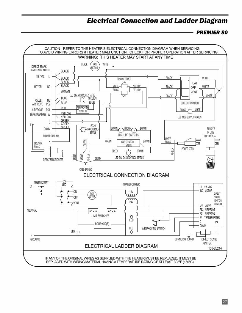
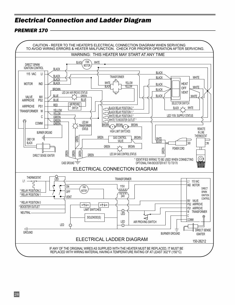
Electrical Connection and Ladder Diagram
27
CAUTION - REFER TO THE HEATER'S ELECTRICAL CONNECTION DIAGRAM WHEN SERVICINGTO AVOID WIRING ERRORS & HEATER MALFUNCTION. CHECK FOR PROPER OPERATION AFTER SERVICING.
WARNING: THIS HEATER MAY START AT ANY TIME
IF ANY OF THE ORIGINAL WIRES AS SUPPLIED WITH THE HEATER MUST BE REPLACED, IT MUST BE REPLACED WITH WIRING MATERIAL HAVING A TEMPERATURE RATING OF AT LEAST 302°F (150°C)
BLACKHEATOFFVENT
WHITE
WHITE
BLACK
WHITE
ELECTRICAL CONNECTION DIAGRAM
DIRECT SENSE IGNITER
DIRECT SPARKIGNITIONCONTROL
L1 115 VACIND MOTOR
MV VALVEPS2 AIRPROVEPS1 AIRPROVEW TRANSFORMERCCOMM
DIRECT SPARKIGNITION CONTROL
GREEN
LED 24V GAS CONTROL STATUS
BURNER GROUND
LED 115V SUPPLY STATUS
LED 24VTRANSFORMER
STATUS
LED 24V AIR PROVE STATUS
BLUE
WHITEBLACK
BROWN
CASE GROUND
GREEN
GREE
N
GREE
NGR
EEN
GREE
N
GREE
N
BROWN
GREENBLUE
ELECTRICAL LADDER DIAGRAM
BROWN
YELLOW
BLACK
BLACKBLACKBLACK
115 VAC LI
MOTOR IND
VALVE MVAIRPROVE PS2
C
COMM
SELECTOR SWITCH
WHITEBLACK
REMOTE IN LINE
THERMOSTAT
POWER CORD
TRANSFORMER
BLACK WHITE
BROWN
BROWNBROWN
GREEN
HIGH LIMIT SWITCHES
GAS CONTROL VALVE
AIR PROVINGSWITCH
WHITE YELLOWBLACK YELLOW
FANMOTOR
BLUE
GREENGREENGREEN
GREY ORBLACK
REDYELLOW
AIRPROVE PS1TRANSFORMER W
DIRECT SENSE IGNITER
BLACK
NEUTRAL
BURNER GROUND
LED
LED
LEDSOLENOID(S)
LIMIT SWITCHES
AIR PROVING SWITCH
ONOFFVENT
THERMOSTAT
LED
GROUND
L1 TRANSFORMER
115V
24V
150-26214
FAN MOTOR
PREMIER 80
Electrical Connection and Ladder Diagram
28
CAUTION - REFER TO THE HEATER'S ELECTRICAL CONNECTION DIAGRAM WHEN SERVICINGTO AVOID WIRING ERRORS & HEATER MALFUNCTION. CHECK FOR PROPER OPERATION AFTER SERVICING.
IF ANY OF THE ORIGINAL WIRES AS SUPPLIED WITH THE HEATER MUST BE REPLACED, IT MUST BE REPLACED WITH WIRING MATERIAL HAVING A TEMPERATURE RATING OF AT LEAST 302°F (150°C)
ELECTRICAL CONNECTION DIAGRAM
WARNING: THIS HEATER MAY START AT ANY TIME
BLACKBLACK
HEATOFFVENT
WHITE
WHITE
BLACKBLACK
WHITE
DIRECT SENSE IGNITER
LED 115V. SUPPLY STATUS
DIRECT SPARKIGNITION CONTROL
GREEN
LED 24V GAS CONTROL STATUS
BURNER GROUND
LED 24VTRANSFORMER
STATUS
LED 24V AIR PROVE STATUS
BLUE
WHITEBLACK
BROWN
CASE GROUND
GREEN GREE
N
GREE
NGR
EEN
GREE
N
GREE
N
BROWN
GREENBLUE
ELECTRICAL LADDER DIAGRAM
BROWN
YELLOW
BLACK
BLACKBLACKBLACK
115 VAC LI
MOTOR IND
VALVE MVAIRPROVE PS2
C
COMM
SELECTOR SWITCH
WHITEBLACK
REMOTE IN LINE
THERMOSTAT
POWER CORD
TRANSFORMER
BLACK WHITE
BROWN
BROWNBROWN
GREEN
HIGH LIMIT SWITCHES
GAS CONTROL VALVE
BLACK RELAY POSITION 2 *BLACK RELAY POSITION 1 *WHITE RELAY POSITION 0 *WHITE TO BOOSTER OUTLET *
AIR PROVING SWITCH
WHITE YELLOWBLACK YELLOW
FANMOTOR
BLUE
GREENGREENGREEN
GREY ORBLACK
REDYELLOW
AIRPROVE PS1TRANSFORMER W
* IDENTIFIES WIRING TO BE USED WHEN CONNECTING OPTIONAL FAN BOOSTER KIT TO TS170
DIRECT SPARKIGNITIONCONTROL
L1 115 VACIND MOTOR
MV VALVEPS2 AIRPROVEPS1 AIRPROVEW TRANSFORMERCCOMM
BLACK
NEUTRAL
* BOOSTER OUTLET* RELAY POSITION 0
* RELAY POSITION 1* RELAY POSITION 2
BURNER GROUND
LED
LED
LED
DIRECT SENSE IGNITER
SOLENOID(S)
LIMIT SWITCHES
AIR PROVING SWITCH
ONOFFVENT
THERMOSTAT
LED
GROUND
L1 TRANSFORMER
115V
24V
150-26212
FANMOTOR
PREMIER 170
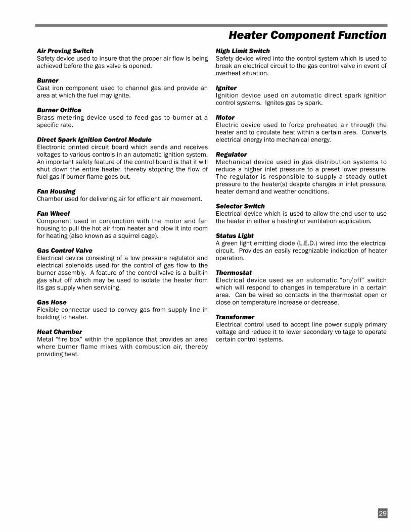
Heater Component Function
Air Proving Switch
Safety device used to insure that the proper air flow is beingachieved before the gas valve is opened.
Burner
Cast iron component used to channel gas and provide anarea at which the fuel may ignite.
Burner Orifice
Brass metering device used to feed gas to burner at aspecific rate.
Direct Spark Ignition Control Module
Electronic printed circuit board which sends and receivesvoltages to various controls in an automatic ignition system.An important safety feature of the control board is that it willshut down the entire heater, thereby stopping the flow offuel gas if burner flame goes out.
Fan Housing
Chamber used for delivering air for efficient air movement.
Fan Wheel
Component used in conjunction with the motor and fanhousing to pull the hot air from heater and blow it into roomfor heating (also known as a squirrel cage).
Gas Control Valve
Electrical device consisting of a low pressure regulator andelectrical solenoids used for the control of gas flow to theburner assembly. A feature of the control valve is a built-ingas shut off which may be used to isolate the heater fromits gas supply when servicing.
Gas Hose
Flexible connector used to convey gas from supply line inbuilding to heater.
Heat Chamber
Metal “fire box” within the appliance that provides an areawhere burner flame mixes with combustion air, therebyproviding heat.
High Limit Switch
Safety device wired into the control system which is used tobreak an electrical circuit to the gas control valve in event ofoverheat situation.
Igniter
Ignition device used on automatic direct spark ignitioncontrol systems. Ignites gas by spark.
Motor
Electric device used to force preheated air through theheater and to circulate heat within a certain area. Convertselectrical energy into mechanical energy.
Regulator
Mechanical device used in gas distribution systems toreduce a higher inlet pressure to a preset lower pressure.The regulator is responsible to supply a steady outletpressure to the heater(s) despite changes in inlet pressure,heater demand and weather conditions.
Selector Switch
Electrical device which is used to allow the end user to usethe heater in either a heating or ventilation application.
Status Light
A green light emitting diode (L.E.D.) wired into the electricalcircuit. Provides an easily recognizable indication of heateroperation.
Thermostat
Electrical device used as an automatic “on/off” switchwhich will respond to changes in temperature in a certainarea. Can be wired so contacts in the thermostat open orclose on temperature increase or decrease.
Transformer
Electrical control used to accept line power supply primaryvoltage and reduce it to lower secondary voltage to operatecertain control systems.
29
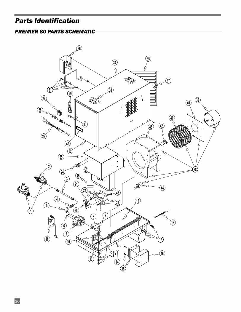
30
18
47
13
45
4644
43 4241
40 39
38
37
36
35
33
32
31
30
2927
28
26
25
24
22
2320
21
19
17
16
1514
12
11 10
9
76
54
3
2
18
34
TS080G
PREMIER 80 PARTS SCHEMATIC
Parts Identification
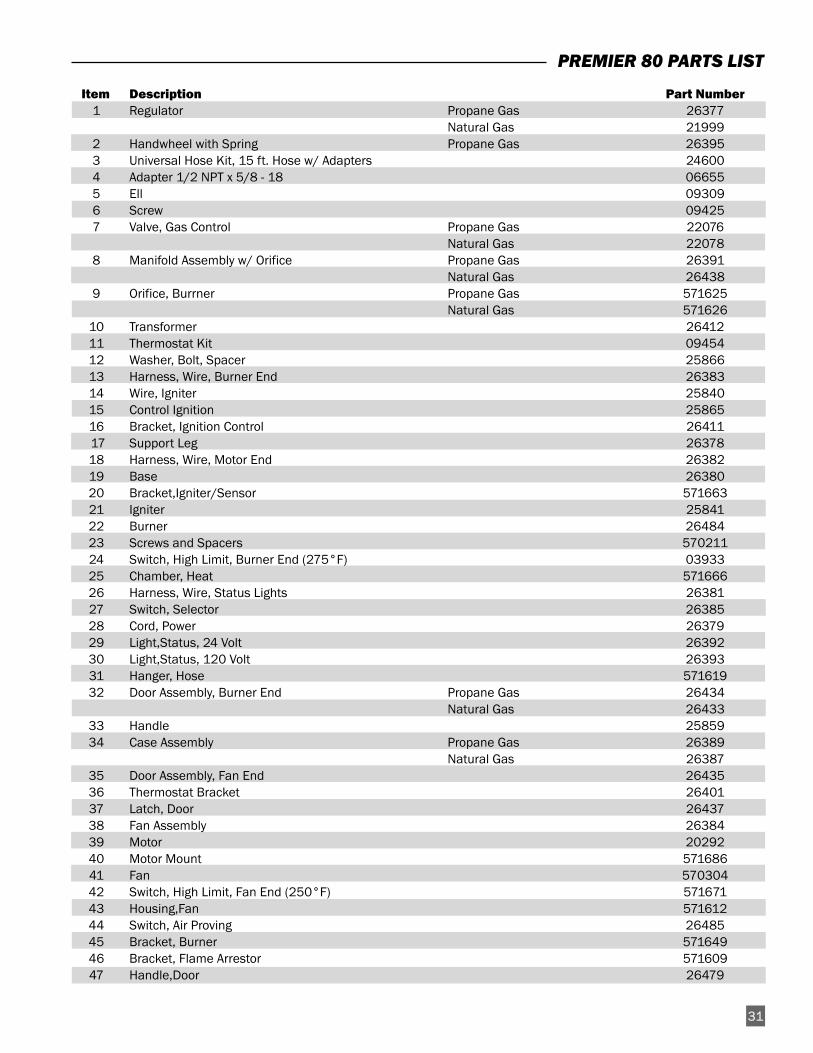
PREMIER 80 PARTS LIST
31
Item Description Part Number1 Regulator Propane Gas 26377
Natural Gas 219992 Handwheel with Spring Propane Gas 263953 Universal Hose Kit, 15 ft. Hose w/ Adapters 246004 Adapter 1/2 NPT x 5/8 - 18 066555 Ell 093096 Screw 094257 Valve, Gas Control Propane Gas 22076
Natural Gas 220788 Manifold Assembly w/ Orifice Propane Gas 26391
Natural Gas 264389 Orifice, Burrner Propane Gas 571625
Natural Gas 57162610 Transformer 2641211 Thermostat Kit 0945412 Washer, Bolt, Spacer 2586613 Harness, Wire, Burner End 2638314 Wire, Igniter 2584015 Control Ignition 2586516 Bracket, Ignition Control 2641117 Support Leg 2637818 Harness, Wire, Motor End 2638219 Base 2638020 Bracket,Igniter/Sensor 57166321 Igniter 2584122 Burner 2648423 Screws and Spacers 57021124 Switch, High Limit, Burner End (275°F) 0393325 Chamber, Heat 57166626 Harness, Wire, Status Lights 2638127 Switch, Selector 2638528 Cord, Power 2637929 Light,Status, 24 Volt 2639230 Light,Status, 120 Volt 2639331 Hanger, Hose 57161932 Door Assembly, Burner End Propane Gas 26434
Natural Gas 2643333 Handle 2585934 Case Assembly Propane Gas 26389
Natural Gas 2638735 Door Assembly, Fan End 2643536 Thermostat Bracket 2640137 Latch, Door 2643738 Fan Assembly 2638439 Motor 2029240 Motor Mount 57168641 Fan 57030442 Switch, High Limit, Fan End (250°F) 57167143 Housing,Fan 57161244 Switch, Air Proving 2648545 Bracket, Burner 57164946 Bracket, Flame Arrestor 57160947 Handle,Door 26479
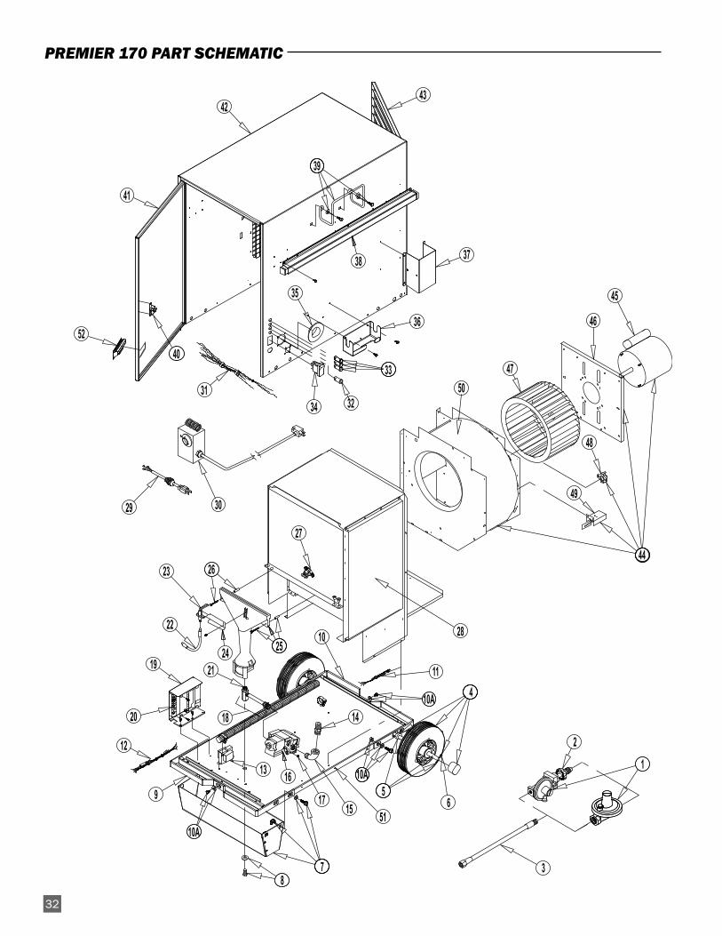
2032
36
17
16
10A
10A
10A
51
49
48
47
46
45
44
4342
41
39
38 37
35
34
33
3231
3029
27
26
2524
23
21
20
19
15
14
13
12
11
10
9
87
56
4
3
2
1
50
2822
18
5240
PREMIER 170 PART SCHEMATIC
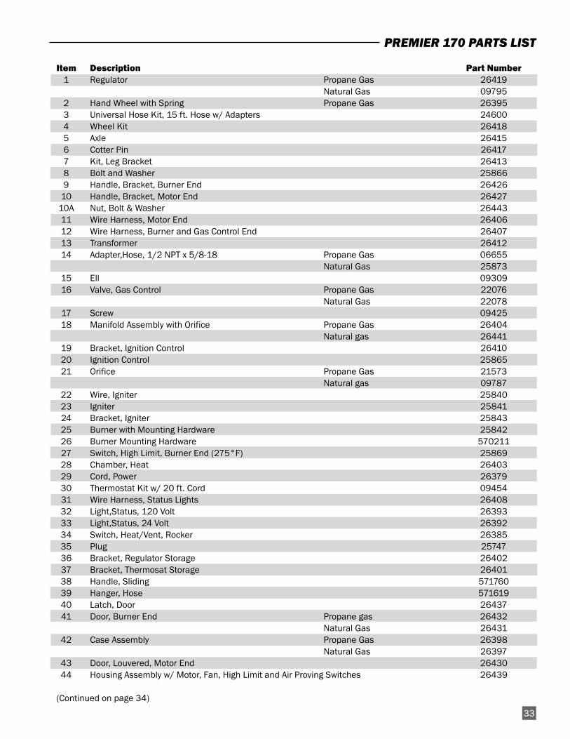
PREMIER 170 PARTS LIST
Item Description Part Number1 Regulator Propane Gas 26419
Natural Gas 097952 Hand Wheel with Spring Propane Gas 263953 Universal Hose Kit, 15 ft. Hose w/ Adapters 246004 Wheel Kit 264185 Axle 264156 Cotter Pin 264177 Kit, Leg Bracket 264138 Bolt and Washer 258669 Handle, Bracket, Burner End 26426
10 Handle, Bracket, Motor End 2642710A Nut, Bolt & Washer 2644311 Wire Harness, Motor End 2640612 Wire Harness, Burner and Gas Control End 2640713 Transformer 2641214 Adapter,Hose, 1/2 NPT x 5/8-18 Propane Gas 06655
Natural Gas 2587315 Ell 0930916 Valve, Gas Control Propane Gas 22076
Natural Gas 2207817 Screw 0942518 Manifold Assembly with Orifice Propane Gas 26404
Natural gas 2644119 Bracket, Ignition Control 2641020 Ignition Control 2586521 Orifice Propane Gas 21573
Natural gas 0978722 Wire, Igniter 2584023 Igniter 2584124 Bracket, Igniter 2584325 Burner with Mounting Hardware 2584226 Burner Mounting Hardware 57021127 Switch, High Limit, Burner End (275°F) 2586928 Chamber, Heat 2640329 Cord, Power 2637930 Thermostat Kit w/ 20 ft. Cord 0945431 Wire Harness, Status Lights 2640832 Light,Status, 120 Volt 2639333 Light,Status, 24 Volt 2639234 Switch, Heat/Vent, Rocker 2638535 Plug 2574736 Bracket, Regulator Storage 2640237 Bracket, Thermosat Storage 2640138 Handle, Sliding 57176039 Hanger, Hose 57161940 Latch, Door 2643741 Door, Burner End Propane gas 26432
Natural Gas 2643142 Case Assembly Propane Gas 26398
Natural Gas 2639743 Door, Louvered, Motor End 2643044 Housing Assembly w/ Motor, Fan, High Limit and Air Proving Switches 26439
(Continued on page 34)
33
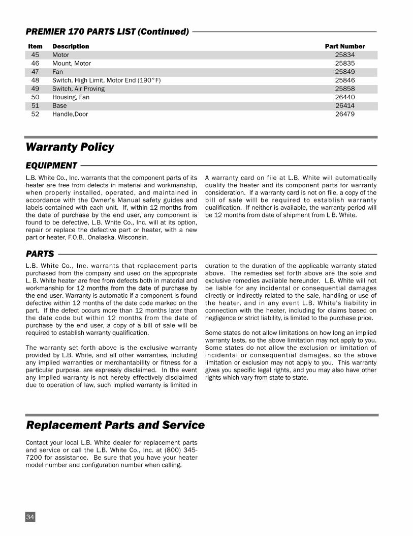
Contact your local L.B. White dealer for replacement partsand service or call the L.B. White Co., Inc. at (800) 345-7200 for assistance. Be sure that you have your heatermodel number and configuration number when calling.
L.B. White Co., Inc. warrants that the component parts of itsheater are free from defects in material and workmanship,when properly installed, operated, and maintained inaccordance with the Owner’s Manual safety guides andlabels contained with each unit. If, within 12 months fromthe date of purchase by the end user, any component isfound to be defective, L.B. White Co., Inc. will at its option,repair or replace the defective part or heater, with a newpart or heater, F.O.B., Onalaska, Wisconsin.
A warranty card on file at L.B. White will automaticallyqualify the heater and its component parts for warrantyconsideration. If a warranty card is not on file, a copy of thebil l of sale wil l be required to establish warrantyqualification. If neither is available, the warranty period willbe 12 months from date of shipment from L B. White.
Warranty Policy
Replacement Parts and Service
EQUIPMENT
PARTS
L.B. White Co., Inc. warrants that replacement partspurchased from the company and used on the appropriateL. B. White heater are free from defects both in material andworkmanship for 12 months from the date of purchase bythe end user. Warranty is automatic if a component is founddefective within 12 months of the date code marked on thepart. If the defect occurs more than 12 months later thanthe date code but within 12 months from the date ofpurchase by the end user, a copy of a bill of sale will berequired to establish warranty qualification.
The warranty set forth above is the exclusive warrantyprovided by L.B. White, and all other warranties, includingany implied warranties or merchantability or fitness for aparticular purpose, are expressly disclaimed. In the eventany implied warranty is not hereby effectively disclaimeddue to operation of law, such implied warranty is limited in
duration to the duration of the applicable warranty statedabove. The remedies set forth above are the sole andexclusive remedies available hereunder. L.B. White will notbe liable for any incidental or consequential damagesdirectly or indirectly related to the sale, handling or use ofthe heater, and in any event L.B. White's liability inconnection with the heater, including for claims based onnegligence or strict liability, is limited to the purchase price.
Some states do not allow limitations on how long an impliedwarranty lasts, so the above limitation may not apply to you.Some states do not allow the exclusion or limitation ofincidental or consequential damages, so the abovelimitation or exclusion may not apply to you. This warrantygives you specific legal rights, and you may also have otherrights which vary from state to state.
34
PREMIER 170 PARTS LIST (Continued)
Item Description Part Number45 Motor 2583446 Mount, Motor 2583547 Fan 2584948 Switch, High Limit, Motor End (190°F) 2584649 Switch, Air Proving 2585850 Housing, Fan 2644051 Base 2641452 Handle,Door 26479