Embed Size (px)
Citation preview

1
OWNER´S MANUAL800.4

2
TABLE OF CONTENTS
Introduction
Package contents ......................................................................................................
Safety instructions ......................................................................................................
Technologies
DTR.............................................................................................................
Ultra Compact PCB.......................................................................... Vibration Absorption Device......................................................... Low Battery consumption.............................................................
Assembling and Disassembling the plastic cover...................................
Panels description
Audio inputs and controls............................................................
Power inputs and audio outputs (until 09/2020)............. Power inputs and audio outputs (from 10/2020)............
Electrical Dimensioning...........................................................................................
Audio inputs
RCA inputs............................................................................................
High inputs............................................................................................
Installation sequence.................................................................................................
Wiring diagram Four channels wiring diagram...................................................
Three channels wiring diagram................................................
Two channels wiring diagram....................................................
Procedure for setting the gain..............................................................................
Crossovers set up.......................................................................................................
Technical specs
Parameters.........................................................................................
Dimensional data............................................................................
3
3
4
5
5
6
6
7
8
9
10
11
11
11
12
13
13
14
14
15
16
16
...................................................................................................................
2

3
DEAR CUSTOMER,
CONGRATULATIONS ON ACQUIRING A PRODUCT WITH THE HIGHEST QUALITY AND TECHNOLOGY!
You have just purchased a SounDigital product of the highest technology and quality, so we thank you for your confidence.
SounDigital products are made with raw materials of the highest quality standards, and the most modern processes, equipment and technology are used in their production.
On this manual you will learn about the product, its features and characteristics, in order to obtain the best result and to be able to enjoy your music with SounDigital quality and power.
To better understand and take advantage of all the functions of the product and use it safely, read this manual carefully and if you have any questions, consult our support by email [email protected].
PACKAGE CONTENTS
- 1 EVOX Amplifier
- 1 Installation quick guide with warranty card
- 1 Allen wrench 2.5mm
- 2 Cables for high level input
- 1 Promotional sticker
INTRODUCTION

4
SAFETY INSTRUCTIONS
THIS "WARNING" SIGN ALERTS THE USER OF IMPORTANT INFO. NOT FOLLOWING
THIS INSTRUCTIONS MAY CAUSE INJURIES TO THE USER OR DAMAGE TO THE
EQUIPMENT.Warning!
To prevent injuries to the user or damage to the amplifier, read all safety instructions written on this manual;
If you are insecure about the installation of this equipment, get in touch with our tech support or with a professional specialized in car audio installation;
Before proceeding with the installation of any electric equipment on your vehicle, unplug the negative (-) terminal of the battery to avoid fires, injuries or damages;
Use your sound system safely. The continuous exposure to sound pressures over 85dB may cause irreversible hearing damage;
This equipment is for use in automotive DC voltage batteries between 12.6 and 14.4 volts. Before installing the equipment, check voltage of the batteries;
Do not install the amplifier in places exposed to water, dirt or humidity;
Choose a ventilated place to install the amplifier and avoid blocking the side ventilation windows;
Mount the amplifier in a secure way. Avoid mounting it on metallic parts of the vehicle, because it may cause ground looping (noise);
Make sure that the location chosen for the amplifier installation does not effect the operation of the vehicle;
When passing cables through metallic walls, use rubber O-rings to avoid cable cutting and short-circuits.
Clean the amplifier periodically with brush or dry cloth to assure the thermal efficiency of the heatsink.
This product may reach temperatures over 60°C/140°F. Make sure it is cold before touching it;
Be careful when making holes in the vehicle. Make sure you are not making holes in the fuel tank, brake lines or electrical cables of the vehicle
Make sure the cables are properly secured throughout the installation;
Wear gloves, safety glasses and and all necessary PPE during the installation of SounDigital amplifiers.

5
TECHNOLOGIES
The DTR* is a dynamic thermal recovery system which always maintains a high efficiency of the amplifier by accelerating the thermal exchange of electronic components with the heatsink
* Patent. Required
ALUMINIUMHEATSINK
CONDUCTIVECOOPER LAYER
ELECTRONICCOMPONENT
DYNAMIC THERMAL RECOVERY - DTR
An intelligent layout, with great use of the
PCB area and the use of modern
components with reduced structure
guarantee SounDigital products a
compact design, at the same time robust
and with excellent thermal efficiency.
ULTRA COMPACT PCB

6
TECHNOLOGIES
VIBRATION ABSORPTION DEVICE
*Efficiency measured at power supply only
SounDigital amplifiers are known for their low
consumption of battery, and this feature was
improved on the EVOX Line. The new I-
POWER SUPPLY is even more modern, which
replaces the old toroidal transformers by a new
generation of "E-E" core transformers delivers
efficiency above 90% *,ensuring more hours of
sound without battery recharge.
I - POWER SUPPLY
SounDigital added a new device to the EVO X products which act like shock absorbers reducing the impact of vibration on the eletronic circuit board, thereby increasing the life and reliability of the amplifiers.

7
1 2
21
A
B
DISASSEMBLING OF THE PLASTIC COVER
ASSEMBLING THE PLASTIC COVER
The plastic covers have the function of finishing and hiding the amplifier fixing screws. To disassembling and assembling them, follow the instructions below.
1. Carefully pull out the top of plastic cover to release the upside latches, as shown in the picture 1.
2. Slide up the plastic cover in a continuous movement to remove it.
1. To fit the plastic cover back, carefully insert the point A of the plastic cover into point B of the
amplifier, slowly sliding it down.
2. Gently press the sides of the top of the plastic cover towards the bottom of the amplifier until
you hear a clicking noise.
EN
ASSEMBLING AND DISASSEMBLING THE PLASTIC COVER

8
X-OVER X-OVERX-OVER X-OVER
PANELS DESCRIPTION
1
3
811 6 12
79 105
2
4
Variable crossover control - 45Hz to 850Hz
High Level audio input(To connect to the speaker output of the headunit)
Crossover SwitchLow Pass - Full - High Pass
Variable Gain Control
Audio input - RCA connector
2
4
6
8
10
12
1
3
5
7
9
11
CH1/CH2
CH1/CH2
CH1/CH2
CH1/CH2
CH1
CH3
CH3/CH4
CH3/CH4
CH3/CH4
CH3/CH4
CH2
CH4

9
PANELS DESCRIPTION
"Power ON" LED indicator (Blue)
Negative power supply connector (GND)
Remote power supply connector (REM)
Positive power supply connector (+12VDC)
Positive speaker connector
Positive speaker connector
Shared connector between channels 3 (+) and 4 (-)
Shared connector between channels 1 (+) and 2 (-)
Negative speaker connector
Negative speaker connector
14
15
16
18
20
22
13
17
19
21
-
CH1/CH2
CH4
CH3
-
-
-
CH1
CH3/CH4
CH2
13 14 15 16 17 18 19 20 21 22
Products manufactured until September 2020
10
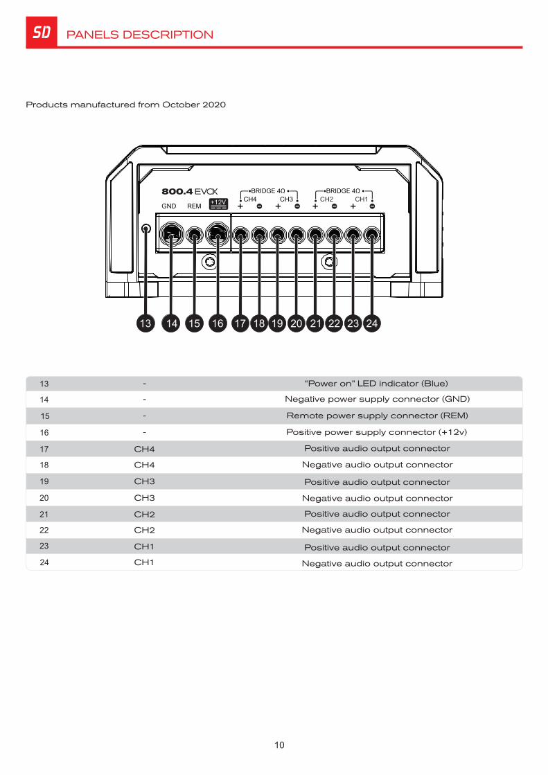
PANELS DESCRIPTION
“Power on” LED indicator (Blue)
Negative power supply connector (GND)
Remote power supply connector (REM)
Positive power supply connector (+12v)
Positive audio output connector
Positive audio output connector
Negative audio output connector
Negative audio output connector
Positive audio output connector
Positive audio output connector
14
15
16
19
21
22
24
13
17
20
23
-
CH4
CH3
-
-
-
CH1
CH3
CH2
CH2
CH1
13 14 15 16 17 18 19 20 21 22 23 24
Negative audio output connector
Negative audio output connector
18 CH4
Products manufactured from October 2020

11
ELECTRICAL DIMENSIONING AND AUDIO INPUTS
ELECTRICAL DIMENSIONING
For proper operation of your SounDigital amplifier, you need the proper dimensioning of the electrical system and the cables used.
The table below shows the minimum section of GND cables, +12VDC cables and speaker output cables according to the power generated by the amplifier.
We recommend the use of ONLY OFC (Oxygen Free Copper) Cables on the installation of our products.
AUDIO INPUTS
RCA AND HIGH INPUTS SHOULD NOT BE USED SIMULTANEOUSLY OR YOU MAY DAMAGE THE AMPLIFIER.
Warning!
High signal inputs
RCA Inputs
XXX
All RCA Inputs must be connected for the 4 channels to work.
All High signal Inputs must be connected for the 4 channels to work.
High input must be used when the main unit does not have RCA outputs.
When hi inputs is used, no remote connection is required, the amplifier recognizes the audio signal and switches on.
If your source unit is not able to turn on the amplifier through the high level input, the remote input should be connected normally.
POWER CABLE
GROUND CABLE
SPEAKER CABLE
800WRMS
10mm² - 7 AWG

12
Ø Mount the amplifier in such a way you have access to the connectors;
Ø Install the power cables in the vehicle properly, starting from the battery to the fuse holder or circuit breaker, use the cable with the appropriate size. Make all connections, install fuse holders or circuit breakers, but without placing the fuses or with the circuit breakers in the "Off" position.
Ø Connect the power cables in to the amplifier, observing the polarity. Connect all the positive cables from the fuse holder or circuit breaker to the positive conector of the amplifier and all the negative power cables from the batteries to the negative connector of the amplifier;
Ø The ground cable must be as short as possible and must be connected to the vehicle chassis and the battery negative;
Ø Install the signal input cables in a proper way, distant from the power cables;
Ø Connect the RCA or the high signal input cables to the head unit and amplifiers;
Ø Install the audio output cables with the appropriate section , distant from the power and audio input cables;
Ø Connect the audio output cables to the amplifier and speakers respecting the positive (+) and negative (-) polarities;
Ø Install the remote cable with the power cables, using 1.5mm² (15 AWG) cable or thicker;
Ø Connect the remote power cable to the amplifier's "REM" terminal at the main unit's remote power output (when not using the high level signal inputs);
Ø Before powering the system, verify all the connections and make sure there are no mistakes or short-circuits on the power and ground cables;
Ø ;Reconnect the ground of the batteries
Ø Check if the headunit is turned off and then place the fuses in the fuse holders or switch the circuit breakers on;
Ø Turn on the main unit and the amplifier will turn on the "On" LED indicating that it is in operation.
INSTALLATION SEQUENCE
Warning!
Warning!
Remove the paint betweenthe terminal and chassis

13
WIRING DIAGRAM
4 CHANNEL WIRING DIAGRAM
3 CHANNEL WIRING DIAGRAM
ÈSee "Audio Inputs"on page 10
ÈSee "Audio Inputs"on page 10
* Check the minimum speaker impedance at spacs table
* Check the minimum speaker impedance at spacs table

14
WIRING DIAGRAM / GAIN SETING
2 CHANNEL WIRING DIAGRAM
MODEL BRIDGE / POWERSTEREO / POWER STEREO OUTPUT VOLTAGE BRIDGE OUTPUT VOLTAGE
4Ω/ 400W2 / 200WΩ 20.0 V 40.0 V800.4
ÈSee "Audio Inputs"on page 10
GAIN SETING
Necessary equipament:
Ø Digital AC voltmeter;
Ø Media with sine wave test tone 60Hz recorded at 0db;
Ø Screwdriver 1/8" ( for gain set)
Set up procedure
This procedure is the same for both Ø
gain controls;
Ø Turn the gain control all the way down.
Ø Disconnect the output cables from the amplifier outputs;
Ø Turn off all processing (bass, treble, loudness, EQ, etc.);
Ø Set the source unit volume to 3/4 of full volume.
Ø Set the source unit's fader control to center position;
Ø Set the crossover selector switch in "F"
Ø Use a 60 Hz sine wave
Ø Connect the AC voltmeter to the speaker output connectors of the amplifier. Make sure you test the voltage at the correct connectors (+ and –);
Ø Increase the gain control until the target voltage is observed with the voltmeter (see the chart below);
Ø Once you have adjusted the amplifier to its correct voltage output, turn off the source uni t and reconnect the speaker(s)
Download the tracks for set up in https://soundigitalusa.com/tracks-for-set-up/
* Check the minimum speaker impedance at spacs table

15
CROSSOVER SET UP
ØSwitch Key to "F" position (Full Range): All the frequencies are reproduced.
ØSwitch key to "HP" - Set in the variable control between 45Hz and 850Hz ("A") where you want to perform the high pass cut filter;
"F" All the frequencies are reproduced;"LP " Set in the variable control on Low Pass Function;"HP " Set in the variable control on High Pass Function.
0dB
-3dB
5Hz 22kHz
dB
Hz
-3dB
c/2ƒHighPass
cƒHighPass
A
0dB
-12dB
dB
Hz
ØSwitch key to "LP" - Set in the variable control between 45Hz and 850Hz ("B") where you want to perform the low pass cut filter;
-3dB
0dB
-12dB
LowPass
B
cƒ c*2ƒLowPass
dB
Hz

16
TECHNICAL SPECS
Power RMS Bridge @ 8Ω*
Power RMS Bridge @ 4Ω*
Power RMS @ 4Ω*
Power @ 2Ω*
Frequency Response (-3dB)
Low Pass filter (12dB/oct)
Operating Voltage
SNR
Input Sensitivity
Current Draw (Music)
Total Efficiency
Damping Factor (@100Hz nominal impedance)
Stereo Minimum Impedance
Bridge Minimum Impedance
Fuse (music)
Recommended batery
Current Draw (Max)
High Pass filter (12dB/oct)
2 X 264W
2 X 400W
4 X 132W
4 X 200W
5Hz ~ 22kHz
8V ~ 16V
91dB
0.2 ~ 4V
40A
80A
79%
200
2Ω �
4Ω �
40A
60Ah
45Hz ~ 850Hz
45Hz ~ 850Hz
*Power at 12.6V @ 60Hz with a maximum THD of 1%.
PARAMETERS
DIMENSIONAL DATA
Net Weight: 1.45 lb (0.66 kg)Gross Weight: 1.74 lb (0.80 kg)
800.4
1.9
" (5
0m
m)
5.3" (134mm)
4.0
" (1
01m
m)
4.4
" (1
13m
m)
5.8" (148mm)

17