Embed Size (px)
Citation preview

990 SUPER DUKE990 SUPER DUKE R
KTM Sportmotorcycle AG A–5230 Mattighofenwww.ktm.at
11/2006 FOTO: MITTERBAUERKTM Group Partner
ART. NR. 3.211.151 EN
OWNER’S MANUAL 2007

INTRODUCTION »
All information contained is without obligation. KTM-Sportmotorcycle AG particularly reserves the right to modify any equipment, technical specifications, prices,colors, shapes, materials, services, service work, constructions, equipment and the like so as to adapt them to local conditions or to cancel any of the above items,all without previous announcement and without giving reasons. KTM may stop manufacturing certain models without previous notice. KTM shall not be held liablefor any deviations of availability and/or ability to deliver, illustrations, descriptions, printing and/or other errors. The illustrated models partly contain extra equip-ment, which is not applied to standard models. © 2006 by KTM-SPORTMOTORCYCLE AG, Mattighofen AUSTRIA; All rights reserved; Reprint, also in extracts, with written allowance of KTM-SPORTMOTORCYCLE AG,Mattighofen only.
COMSUMER INFORMATION FOR AUSTRALIA ONLY Tampering with noise control system prohibited Owners are warned that the law may prohibit:(a) The removal or rendering inoperative by any person other than for purposes of maintenance, repair or replacement, of any device or element of design incorpo-
rated into any new vehicle for the purpose of noise control prior to its sale or delivery to the ultimate purchaser or while it is in use; and(b) the use of the vehicle after such device or element of design has been removed or rendered inoperative by any person.
Frame number
Engine number
Key number
Stamp of dealer
We would like to congratulate you on your purchase of a KTM motorcycle. You are now the owner of a state-of-the-art sport motorcycle that guarantees to bring youlots of fun and enjoyment, provided that you clean and maintain it appropriately.Please insert the serial numbers of your motorcycle in the boxes below:
In accordance with the international quality management ISO 9001 standard, KTM uses quality assuranceprocesses that lead to the highest possible product quality.
1

IMPORTANT INFORMATION »INTENDED PURPOSE The 990 Super Duke is designed to resist the usual wear and tear of paved roads but is not designed for race courses or off-road use.
The 990 Super Duke R is designed to resist the usual wear and tear of paved roads or race courses but is not designed for off-road use.
OWNER'S MANUALCarefully read the entire Owner's Manual before you start riding your motorcycle, even if this will take a little time. It contains use-ful tips and information on the best way to handle the motorcycle and how to protect yourself from injuries. The Manual also con-tains important information on service and maintenance. In your own interest, pay particular attention to the information markedas follows:
– Ignoring these instructions, can endanger your body andyour life.
– Ignoring these instructions could cause damage to partsof your motorcycle or that the motor-cycle is not road-safeanymore.
The Owner's Manual corresponded to the latest information available for this model series at the time it was printed. Minor devia-tions resulting from enhancements to the motorcycle design cannot be entirely precluded. The Owner's Manual is an integral partof the motorcycle and must be handed over to the new owner when the motorcycle is sold.
SERVICEObservance of the service, maintenance and operating instructions for the engine and chassis specified in the Owner's Manual isa prerequisite for faultless operation and the avoidance of premature wear. Please observe the prescribed breaking-in periods, inspec-tion intervals and service intervals. Strict observance will significantly prolong the service life of your motorcycle.
The use of the motorcycle under extreme conditions, e.g. on the race course, can cause above average wear to components suchas the brakes. In this case it may become necessary to service or replace wear parts before the service limit specified in the main-tenance schedule has been reached.
2

IMPORTANT INFORMATION »WARRANTY The service work specified in the „Lubrication and Maintenance Schedule“ must be performed by an authorized KTM workshop.This is the only place that has the qualified technicians and the special tools required for the 990 Super Duke / R. Be sure to havethe workshop verify all service work carried out in the service manual to avoid losing your right to claim under the warranty.The warranty or guarantee shall become void for damage and consequential damage caused by manipulations or conversions to themotorcycle.
AUTOMOTIVE FLUIDS The fuels, lubricants and liquids specified in the Owner's Manual or automotive fluids with equivalent specifications must be usedin accordance with the maintenance schedule.
SPARE PARTS, ACCESSORIES For your own safety, only use spare parts and accessories approved by KTM. KTM shall not assume any liability for other productsor consequential damage resulting from the use of such products.
ENVIRONMENTMotorcycle driving is a wonderful sport and we hope that you will be able to enjoy it to the full. It may, however, involve potentialproblems for the environment or lead to conflicts with others. These problems or conflicts can be avoided if the motorcycle is usedresponsibly. To safeguard the future of motorcycle sports, make sure that you use the motorcycle in accordance with the law, showthat you are environmentally conscious and respect the rights of others.
Enjoy driving your motorcycle !
KTM SPORTMOTORCYCLE AG 5230 MATTIGHOFEN, AUSTRIA
3

INDEX » 4
INTRODUCTION . . . . . . . . . . . . . . . . . . . . . . . . . . . . . . . . . .1IMPORTANT INFORMATION . . . . . . . . . . . . . . . . . . . . . . . . . .2SERIAL NUMBER LOCATIONS . . . . . . . . . . . . . . . . . . . . . . . .6
Chassis number, Type label . . . . . . . . . . . . . . . . . . . . . . . . .6Engine number, engine type . . . . . . . . . . . . . . . . . . . . . . . .6
OPERATION INSTRUMENTS . . . . . . . . . . . . . . . . . . . . . . . . .7Clutch lever . . . . . . . . . . . . . . . . . . . . . . . . . . . . . . . . . . .7Hand brake lever . . . . . . . . . . . . . . . . . . . . . . . . . . . . . . . .7Combined instrument . . . . . . . . . . . . . . . . . . . . . . . . . . . .8Function buttons on combined instrument . . . . . . . . . . . . .8Combined instrument display . . . . . . . . . . . . . . . . . . . . . .8Cooling liquid temperature display . . . . . . . . . . . . . . . . . .12Tachometer . . . . . . . . . . . . . . . . . . . . . . . . . . . . . . . . . . .12Indicator lamps . . . . . . . . . . . . . . . . . . . . . . . . . . . . . . . .13Ignition lock . . . . . . . . . . . . . . . . . . . . . . . . . . . . . . . . . .14Combination switch . . . . . . . . . . . . . . . . . . . . . . . . . . . . .14Starter tip switch, Emergency OFF tip switch . . . . . . . . . .15Filler cap . . . . . . . . . . . . . . . . . . . . . . . . . . . . . . . . . . . .15Seat lock, removing the seat . . . . . . . . . . . . . . . . . . . . . .16Baggage loops . . . . . . . . . . . . . . . . . . . . . . . . . . . . . . . .16Tool set . . . . . . . . . . . . . . . . . . . . . . . . . . . . . . . . . . . . .17Helmet lock . . . . . . . . . . . . . . . . . . . . . . . . . . . . . . . . . .17Holding strap . . . . . . . . . . . . . . . . . . . . . . . . . . . . . . . . .17Shift lever . . . . . . . . . . . . . . . . . . . . . . . . . . . . . . . . . . . .18Side stand . . . . . . . . . . . . . . . . . . . . . . . . . . . . . . . . . . .18Foot brake pedal . . . . . . . . . . . . . . . . . . . . . . . . . . . . . . .18Footrests . . . . . . . . . . . . . . . . . . . . . . . . . . . . . . . . . . . .19Compression damping of fork . . . . . . . . . . . . . . . . . . . . . .19Rebound damping of fork . . . . . . . . . . . . . . . . . . . . . . . . .19Spring preload of the fork . . . . . . . . . . . . . . . . . . . . . . . . .20
Damping action during compression of shock absorber . . . .20Rebound damping of shock absorber . . . . . . . . . . . . . . . . .21
GENERAL TIPS AND WARNINGS FOR STARTING THE MOTORCYCLE . . . . . . . . . . . . . . . . . . . . . . . . . . . . . . .22
Instructions for initial operation . . . . . . . . . . . . . . . . . . . .22Running in the LC8 engine . . . . . . . . . . . . . . . . . . . . . . . .22Accessories and payload . . . . . . . . . . . . . . . . . . . . . . . . . .23
DRIVING INSTRUCTIONS . . . . . . . . . . . . . . . . . . . . . . . . . .24Check the following before each start . . . . . . . . . . . . . . . .24Starting the engine . . . . . . . . . . . . . . . . . . . . . . . . . . . . .26Starting off . . . . . . . . . . . . . . . . . . . . . . . . . . . . . . . . . . .27Shifting/Riding . . . . . . . . . . . . . . . . . . . . . . . . . . . . . . . .27Braking . . . . . . . . . . . . . . . . . . . . . . . . . . . . . . . . . . . . .28Stopping and parking . . . . . . . . . . . . . . . . . . . . . . . . . . . .29Fuel . . . . . . . . . . . . . . . . . . . . . . . . . . . . . . . . . . . . . . . .30
PERIODIC MAINTENANCE SCHEDULE . . . . . . . . . . . . . . . . .32MAINTENANCE WORK ON CHASSIS AND ENGINE . . . . . . . .36
Adjusting the fork and shock absorber . . . . . . . . . . . . . . .37Adjusting compression damping of fork . . . . . . . . . . . . . . .37Adjusting rebound damping of fork . . . . . . . . . . . . . . . . . .37Adjusting the spring preload on the fork . . . . . . . . . . . . . . .38Compression damping of shock absorber . . . . . . . . . . . . . .38Rebound damping of shock absorber . . . . . . . . . . . . . . . . .39Checking the chain tension . . . . . . . . . . . . . . . . . . . . . . .40Correcting the chain tension . . . . . . . . . . . . . . . . . . . . . .40Chain maintenance . . . . . . . . . . . . . . . . . . . . . . . . . . . . .41Checking the chain for wear . . . . . . . . . . . . . . . . . . . . . . .41General information on KTM disk brakes . . . . . . . . . . . . . .42Adjusting the basic position of the hand brake lever . . . . . .44Checking the front brake fluid level . . . . . . . . . . . . . . . . .44

INDEX » 5
Checking the front brake pads . . . . . . . . . . . . . . . . . . . . .45Checking the rear brake fluid level . . . . . . . . . . . . . . . . . .46Checking the rear brake pads . . . . . . . . . . . . . . . . . . . . . .46Dismounting and remounting the front wheel . . . . . . . . . .48Dismounting and mounting the rear wheel . . . . . . . . . . . . .50Tires, air pressure . . . . . . . . . . . . . . . . . . . . . . . . . . . . . .51Battery . . . . . . . . . . . . . . . . . . . . . . . . . . . . . . . . . . . . . .52Removing and remounting the battery . . . . . . . . . . . . . . .53Charging the battery . . . . . . . . . . . . . . . . . . . . . . . . . . . .54Jump start . . . . . . . . . . . . . . . . . . . . . . . . . . . . . . . . . . .54Main fuse . . . . . . . . . . . . . . . . . . . . . . . . . . . . . . . . . . .55Fuses for individual power consumers . . . . . . . . . . . . . . . .56Replacing the headlight lamp . . . . . . . . . . . . . . . . . . . . .57Adjusting the headlight range . . . . . . . . . . . . . . . . . . . . . .58Replacing the brake light and taillight bulbs . . . . . . . . . . .59Replacing the flasher bulbs . . . . . . . . . . . . . . . . . . . . . . .59Cooling system . . . . . . . . . . . . . . . . . . . . . . . . . . . . . . . .60Checking the cooling liquid level in the compensating tank . .61Checking the cooling liquid level in the radiator . . . . . . . . .62Bleeding the cooling system . . . . . . . . . . . . . . . . . . . . . .62Changing the basic position of the clutch lever . . . . . . . . .64Checking the oil level of the hydraulic clutch . . . . . . . . . . .64Adjusting the handlebar tilt . . . . . . . . . . . . . . . . . . . . . . .64How to change the handlebar position (Super Duke R) . . . .65Adjusting the steering damper (Super Duke R) . . . . . . . . .65Engine oil . . . . . . . . . . . . . . . . . . . . . . . . . . . . . . . . . . . .66Checking the engine oil level . . . . . . . . . . . . . . . . . . . . . .66Refilling engine oil . . . . . . . . . . . . . . . . . . . . . . . . . . . . .67Changing the engine oil and the oil filter, cleaning the oil screen . . . . . . . . . . . . . . . . . . . . . . . . . . .68
TROUBLESHOOTING . . . . . . . . . . . . . . . . . . . . . . . . . . . . . .72CLEANING . . . . . . . . . . . . . . . . . . . . . . . . . . . . . . . . . . . . .77CONSERVATION FOR WINTER OPERATION . . . . . . . . . . . . . .77STORAGE . . . . . . . . . . . . . . . . . . . . . . . . . . . . . . . . . . . . . .78STARTING UP AFTER IMMOBILIZATION . . . . . . . . . . . . . . .78TECHNICAL SPECIFICATIONS – CHASSIS . . . . . . . . . . . . . . .79TECHNICAL SPECIFICATIONS – ENGINE . . . . . . . . . . . . . . .83
Engine oil . . . . . . . . . . . . . . . . . . . . . . . . . . . . . . . . . . . .84HEAD WORD INDEX . . . . . . . . . . . . . . . . . . . . . . . . . . . . . .85CONSUMER INFORMATION FOR USA ONLY . . . . . . . . . . . . .87

Chassis number, Type labelThe chassis number is stamped on the right side of the steering head tube. Enter this num-ber in the field on page no 1.The type label is located on the right frame tube under the seat.
Engine number, engine typeThe engine number and the engine type are stamped into the left side of the engine belowthe engine sprocket. Enter this number on page 1.
SERIAL NUMBER LOCATIONS » 6

Clutch leverThe clutch lever [1] is fitted on the left hand side of the handle bar. The adjusting screw [A]is used to change the original position of the clutch lever (see maintenance work on chas-sis and engine).The clutch is hydraulically actuated and adjusts itself automatically.
Hand brake leverThe hand brake lever [2] is mounted on the handlebar on the right and actuates the frontwheel brake.The adjusting screw [B] is used to change the original position of the hand brakelever (see maintenance work on chassis and engine).
OPERATION INSTRUMENTS » 7
B
2
1
A

OPERATION INSTRUMENTS » 8
1
2
Combined instrument The combined instrument is divided into 4 parts. Function buttons: to select the display modes and basic settings in the displayTachometer: displays the engine speed Indicator lamps: provide additional information on the motorcycle operating condition Display: shows the speed, cooling liquid temperature, time, ambient temperature,
distance traveled (ODO), trip master 1 (TRIP 1), trip master 2 (TRIP 2),distance traveled since the reserve warning lamp went on (TRIP F)
Function buttons on combined instrument MODE [1]Briefly press the MODE button to go to the next display mode. The available display modesare ambient temperature, distance traveled (ODO), trip master 1 (TRIP 1) and trip master2 (TRIP 2). The speed, cooling liquid temperature and time are always displayed.
SET [2]Press the SET button to reset trip master 1 or 2 to 0.
The 3rd button is not programmed.
Combined instrument display TEST When you switch on the ignition, all of the display elements will light up for 1 second forthe function test.
LENGTH The display will change for 1 second to display the circumference of the front wheel in mil-limeters. 1870 mm corresponds to a 17" front wheel.
Then the display will change back to the mode that was activated when the ignition wasswitched off.

OPERATION INSTRUMENTS » 9
1
2
3
SPEED [1]The speed can be displayed in kilometers per hour (km/h) or miles per hour (mph).
CHANGING THE SPEED DISPLAY FROM KM/H - MPH or MPH - KM/HSwitch on the ignition and press the MODE button more than 10 seconds in the ODO mode.
CLOCK [2]The dots between the hours and minutes will blink in the CLOCK display.The clock must be set if the battery was disconnected or if the fuse 6 was blown.
SETTING THE CLOCK Switch on the ignition and select the ODO mode. Press and hold the MODE button whileyou press the SET button more than 1 second. The time will start to blink. Use the MODE button to set the hours. Use the SET button to set the minutes.Then press the MODE and SET buttons simultaneously.
AMBIENT TEMPERATURE [3]The ambient temperature can be displayed in Celsius (°C) or Fahrenheit (°F).
CHANGING THE AMBIENT TEMPERATURE DISPLAY FROM °C - °F or °F - °CSwitch on the ignition and press the MODE button more than 10 seconds in the ambienttemperature mode.
Press the MODE button to go to the next display mode.

OPERATION INSTRUMENTS » 10
1
2
FROST WARNING [1]The frost symbol will start to blink regardless of the mode if the ambient temperature dropsbelow 3°C (37.5°F).
ODO [2]Displays the total kilometers or miles traveled.This figure will not be cleared if the battery is disconnected.

OPERATION INSTRUMENTS » 11
3
2
1
TRIP 1 [1]The trip meter 1 is always active and counts up to 999.9. It is used to measure the lengthof the trip or the distance between 2 refueling stops.
TO RESET TRIP 1 To reset the trip meter 1 to zero, switch on the ignition, select the TRIP 1 display mode andpress the SET button more than 2 seconds.
Press the MODE button to go to the next display mode.
TRIP 2 [2]The trip meter 2 is always active and counts up to 999.9. It is used just like TRIP 1.
TO RESET TRIP 2 To reset the trip meter 2 to zero, switch on the ignition, select the TRIP 2 display mode andpress the SET button more than 2 seconds.
Press the MODE button to go to the next display mode.
TRIP F [3]When the fuel level reaches the reserve mark, the display will automatically switch to TRIPF and begin to count (no matter which display mode was active before). At the same time,the fuel warning lamp will light up. You will still have enough reserve fuel for at least 30kilometers.After refueling, it will take approx. 3 minutes for the fuel lamp to go out, TRIP F to auto-matically reset to 0 and to return to the previous display mode.
NOTE:Press the SET button for 2 seconds to switch off the fuel warning lamp.

TachometerThe tachometer [3] shows the engine speed in revolutions per minute. Do not run the enginebeyond the orange mark at 9500 rpm.The speed limiter will set in at 9600 rpm, drastically reducing the engine power above thisrotational speed.
Cooling liquid temperature display The temperature display [1] is shown in 12 bars. The more bars that light up, the hotter thecooling liquid. When the upper bar lights up 120°C (248°F), all of the bars will start to blinkand the red warning lamp [2] will light up.
Possible causes for an increase in temperature, causing the red warning light for the cool-ing liquid temperature to light up:– Driving too slowly and driving with a heavy load at high air temperatures– Not enough cooling liquid in the system– The ventilator on the left radiator is not running– Improper use of the clutch when driving slowly
OPERATION INSTRUMENTS » 12
1
2
3
heiß /hot /caldo/chaud/caliente
normalnormallynormalementenormalmentnormalmente
kalt / cold / freddo / froid / frío

Indicator lampsThe green indicator lamp will blink in the blinker rhythm when the blinker isswitched on.NOTE: The indicator lamp will blink slower when a blinker is broken.
The green indicator lamp will light up when the gearbox is in an idling position.
The blue indicator lamp will light up when the high beams are switched on.
The red warning light will light up when the cooling liquid has reached a tempera-ture of approx. 120°C (248°F).
The orange warning lamp will light up when the fuel level has reached the reserve mark.At the same time the display will automatically change to TRIP F (see TRIP F).
The red warning lamp lights up when the ignition is switched on but the engine isnot running. When the engine is started, the warning lamp will go out as soon as theoil pressure is high enough.
The orange warning lamp (fuel injection) briefly lights up when the ignition is switchedon. It will go out when the gasoline pressure is high enough. If this warning lamp lights up while driving, a component in the injection system isdefective. The error can be identified by means of a blink code (see Trouble shoot-ing).
The red warning lamp will light up if the voltage in the on-board electrics drops below10 volts. Immediately drive to the nearest authorized KTM workshop and have theelectrical system checked.
OPERATION INSTRUMENTS » 13

Ignition lockThe ignition lock has 3 switching positions.
Ignition off, (engine can't be started)
Ignition on, (engine can be started)
Ignition off, handlebar blocked
To switch the ignition to position turn the ignition key to position and firmly press itinto the lock. Turn the handlebar to the left, then turn the ignition key to the left.The ignition key can be withdrawn in position and .
Combination switchThe rocker switch LIGHTS [1] actuates the high beam or low beam.
High-beam light
Low-beam light
The light signal (high beam) is actuated with button [2].
The indicator switch [3] returns to central position after actuation. Press flasherswitch towards switch housing to switch off the flasher.
The horn is sounded with button [4].
OPERATION INSTRUMENTS » 14
2
1
1
3
4

Starter tip switch, Emergency OFF tip switch The emergency off switch [1] is provided for emergency situations and should not be usedto switch off the engine.The engine is ready for operation in position (ignition circuit and starter circuit are switchedon).The engine cannot be started in position (ignition circuit and starter circuit are inter-rupted).
Use the starter tip switch [3] to operate the electric starter.
Filler capThe filler cap [4] can be locked. It is equipped with a tank ventilation system.To open, insert the ignition key, turn 45° in a clockwise direction and tilt the filler cap back. After refueling, pull out the ignition key and press down on the filler cap until the lock engages.
OPERATION INSTRUMENTS » 15
4
1
3
Seat lock, removing the seat The seat lock [1] can be locked with the ignition key. To remove the seat, insert the ignition key and turn 90° in a clockwise direction. Lift theseat in the back while pressing near the holding strap and pull off towards the back.
To mount the seat, place it on the motorcycle and position the hooks [2] on the bottom ofthe seat behind the dollies [3] on the subframe. Press down on the seat near the holdingstrap while sliding it forwards. The two tabs [4] must hook onto the tank. Turn the ignitionkey in the seat lock 90° in a counterclockwise direction and pull off. Check whether the seatis mounted correctly.
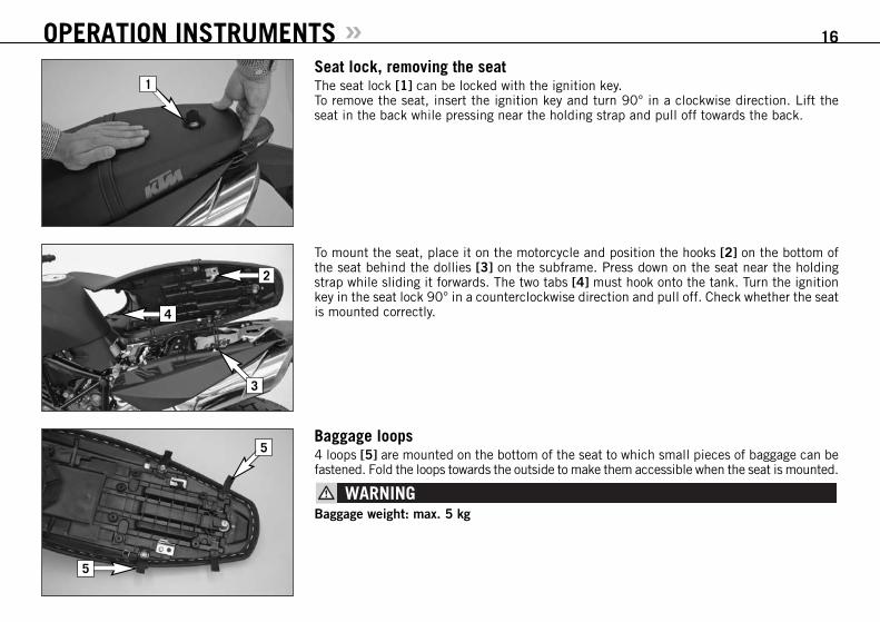
Baggage loops 4 loops [5] are mounted on the bottom of the seat to which small pieces of baggage can befastened. Fold the loops towards the outside to make them accessible when the seat is mounted.
Baggage weight: max. 5 kg
OPERATION INSTRUMENTS » 16
1
2
4
3
5
5

Tool set The tool set [1] is located in the storage compartment under the seat.
Helmet lock The steel rope [2] in the tool bag can be used to secure a helmet. To secure, remove the seat, run the rope through the helmet, attach both ends to the hook[3] and mount the seat.
The helmet lock is provided to secure the helmet to the motorcycle when parked. Do notattach the helmet or other objects to the steel rope while driving. You can easily lose con-trol of the motorcycle.
Holding strap The passenger should hold on to the holding strap [4] or the driver while riding.
OPERATION INSTRUMENTS » 17
1
3
2
4

Shift leverThe shift lever is mounted on the left side of the engine. The position of the gears is shownin the illustration. Neutral, or the idle speed, is located between first and second gear.The basic position of the shift lever can be adjusted according to your seating position (seeMaintenance work).
Side standFold the side stand [1] forward to the stop with your foot and put the weight of the motor-cycle on the stand. Make sure it is standing securely on a firm surface. The side stand islinked to the safety start system; follow the driving instructions.
Foot brake pedalThe foot brake pedal [2] is located in front of the right footrest. Its basic position can beadjusted to your seat position.
OPERATION INSTRUMENTS » 18
1
N
2,3,4,5,6
1
2

FootrestsThe passenger footrests [1] fold up.
Compression damping of fork The fork's damping action during compression travel (compression damping) can be adjusted.This allows you adjust the damping behavior to match your driving style and the payload.The adjusting screws [2] are located on the fork leg axle passage. More information is provided in the chapter „Adjusting the fork and shock absorber“.
Rebound damping of forkThe fork's damping action during rebound travel (rebound damping) can also be adjusted.This allows you adjust the damping behavior to match your driving style and the payload.The adjusting screws [3] are located on the upper end of the fork legs.More information is provided in the chapter "Adjusting the fork and shock absorber.“
OPERATION INSTRUMENTS » 19
1
3
2

Spring preload of the forkThe fork's preload can be adjusted by means of the adjusting screws [1].More information is provided in the chapter „Adjusting the fork and shock absorber“.
Damping action during compression of shock absorberThe shock absorber's damping action during compression travel (compression damping) canbe adjusted. This allows you adjust the shock absorber's damping behavior to match yourdriving style and the payload.The damping rate can be adjusted in the low and high-speed range (Dual Compression Control).The designation low and high-speed refers to the movement of the shock absorber and notto the motorcycle's driving speed.
The adjusting screw [2] for the low-speed range can be adjusted with a screwdriver.
The adjusting screw [3] for the high-speed range can be adjusted with a 17 mm socket wrench.
More information is provided in the chapter „Adjusting the fork and shock absorber“.
OPERATION INSTRUMENTS » 20
1
2
3

Rebound damping of shock absorberThe shock absorber's damping action during rebound travel (rebound damping) can also beadjusted. This allows you adjust the damping behavior to match your driving style and thepayload.The adjusting screw [1] is located on the bottom of the shock absorber.More information is provided in the chapter "Adjusting the fork and shock absorber.“
OPERATION INSTRUMENTS » 21
1

Instructions for initial operation– Make sure the work for the „pre-delivery
inspection“ was performed by your author-ized KTM workshop. The DELIVERY CER-TIFICATE and SERVICE MANUAL willbe handed over when you pick up yourvehicle.
– Read these operating instructions care-fully before your first ride.
– Enter the chassis, engine and key num-bers on page 1.
– Familiarize yourself with the operatingelements.
– Adjust the clutch lever, the hand brakelever, the foot brake lever and the shiftlever in the position that is most conven-ient for you.
– This motorcycle is equipped with a three-way catalytic converter. Leaded fuel willdestroy the converter. Always use unleadedfuel.
– Get used to handling the motorcycle onan empty parking lot, before starting ona longer drive. Also try to drive as slowlyas possible and in standing position, toimprove your feeling for the vehicle.
– You may only be accompanied by a pas-senger if your motorcycle is fitted and reg-istered for such purposes. The passengermust hold on to the supporting strap orthe driver and keep his feet on the pas-senger footrests throughout the ride.
– Hold the handlebars with both handsand leave your feet on the foot rests whiledriving.
– Remove your foot from the foot brakelever when you are not braking. If the footbrake lever is not released the brake padsrub continuously and the braking systemis overheated.
– Do not make any alterations to the motor-cycle and always use ORIGINAL KTMSPARE PARTS. Spare parts from othermanufacturers can impair the safety ofthe motorcycle.
– New tires have a smooth surface, whichmeans that they must be run in to achievefull grip. For this purpose, ride the motor-cycle carefully at moderate speed duringthe first 200 kilometers with new tires,tilting the vehicle at different angles sothat all sections are properly roughened.Tires will not display their full grip char-acteristics until they are properly run in.
– Motorcycles are sensitive to changes inthe weight distribution. Read the sectionon „Accessories and payload“ when car-rying luggage.
– Pay attention to running-in procedure.
Running in the LC8 engineEven finely machined surfaces of engineparts have rougher surfaces than parts thatslide on each other for a long time. Therefore,every engine must be run in. For this reason,do not demand maximum performance fromthe engine for the first 1000 kilometers (620miles). The vehicle must be run in at low,changing performance level for the first 1000
km (620 miles). The maximum number ofrevolutions per minute must not go exceed6500 rpm. Once you have run your enginein for 1000 km, you may push it to its 9500rpm limit , i.e. up to the orange zone indi-cated in the tachometer. Exceeding the abovelisted rotations as well as pushing high rpmwhen the engine is cold will have an adverseeffect on the life of your engine.
– Wear suitable clothing when driving amotorcycle. Clever KTM drivers alwayswear a helmet, boots, gloves and a jacket,regardless of whether driving all day orjust for a short trip. The protective cloth-ing should be brightly colored so thatother vehicle can see you as early aspossible. Your passenger will also needsuitable protective clothing.
– Do not drive after having consumed alcohol.
– Always turn on the light to make surethat other drivers become aware of youas early as possible.
– Drive at a moderate speed for the first fewkilometers of each trip to allow the tiresto reach the necessary operating temper-ature. Maximum road grip is assured whenthe tires are warm.
– The front and rear wheel are allowed tobe fitted only with tires that have thesame profile type.
GENERAL TIPS AND WARNINGS FOR STARTING THE MOTORCYCLE » 22

– The tires must be designed for a speedof over 240 KPH (speed symbol ZR) andmust be released by KTM.
– New tires have a smooth surface, whichmeans that they must be run in to achievefull grip. For this purpose, ride the motor-cycle carefully at moderate speed duringthe first 200 kilometers with new tires,tilting the vehicle at different angles sothat all sections are properly roughened.Tires will not display their full grip char-acteristics until they are properly run in.
– Wheels with a different rim diameter orother rim width may not be mounted oth-erwise the vehicle handling will no longerbe safe.
– Observe the traffic regulations, drivedefensively and trying to look ahead asfar as possible so that any hazards canbe recognized as early as possible.
– The faster you drive, the more sensitiveyour motorcycle will be to crosswind andchanging road conditions. Your motorcy-cle can easily go out of control at highspeeds.
– Choose your driving speed according tothe conditions and your driving skills.
– Drive carefully on unknown roads or onunfamiliar trials.
– Renew the vizor on your helmet on timeso as to ensure optimum vision in any sit-uation. When light shines directly onscratched visor, the operator will beblinded.
– You may only be accompanied by a pas-senger if your motorcycle is fitted and reg-istered for such purposes.
– Never leave your motorcycle without super-vision if the engine is running.
Accessories and payloadAccessory parts and baggage can signifi-cantly decrease a motorcycle's driving stabil-ity. Please observe the following warnings.
– Never drive faster than 130 kph (80 mph)if you have mounted accessory parts onyour motorcycle. Accessory parts can sig-nificantly impair the motorcycle's han-dling, especially in the maximum speedrange.
– Never drive faster than 130 kph (80 mph)if your motorcycle is loaded with casesor other baggage. They will impair themotorcycle's handling at higher speeds andcan easily cause it to go out of control
– If you have cases mounted, do not exceedthe manufacturer's recommended maxi-mum payload.
– Four loops are provided on the bottom ofthe seat to attach your luggage. Makesure your luggage does not extend beyondthe silencer, otherwise it may becomesinged from the heat.
– Make sure your luggage does not coverthe tail light.
– Baggage must be securely and adequatelyfastenend; loose baggage will significantly
impair driving safety.– A high payload will change the motorcy-
cle's handling and considerably increasethe braking distance; adapt your drivingspeed accordingly.
– Never exceed the maximum permissibleladen weight and the axle weights. Themaximum permissible laden weight ismade up of the following components:– Motorcycle ready for operation and tank
full– Luggage– Driver and passenger with protective
clothing and helmet
GENERAL TIPS AND WARNINGS FOR STARTING THE MOTORCYCLE » 23

Check the following before each startWhen you start, the motorcycle must be in perfect mechanical condition. For safety reasons,you should make a habit of performing an overall check of your motorcycle before each start.
The following checks should be performed:
1 FUELCheck the fuel quantity in the tanks.
2 CHAINCheck the tension and condition of the chain. A loose chain can fall off the sprockets and a worn-out chain can tear. In both cases thiscan damage other motorcycle components and cause the motorcycle to go out of con-trol. A chain that is too tight or not greased will cause unnecessary wear to the chainand sprockets.
3 TIRESCheck for damaged tires. Tires showing cuts or dents must be replaced. The tread depthmust comply with the legal regulations. Also check the air pressure. Insufficient treadand incorrect air pressure deteriorate the driving performance.
4 BRAKESCheck correct functioning of the braking system. Check for sufficient brake fluid in thereservoir. The reservoirs have been designed in such a way that brake fluid does not needto be refilled even when the brake pads are worn. If the level of brake fluid falls belowthe minimum value, this indicates a leak in the braking system or completely worn outbrake pads. Arrange for the braking system to be checked by a KTM specialist, as com-plete failure of the braking system can be avoided.Also check the state of the brake hose and the thickness of the brake linings.Check free travel at hand brake lever and foot brake lever.
5 CABLESCheck the throttle cable for correct adjustment and smooth operation.
DRIVING INSTRUCTIONS » 24
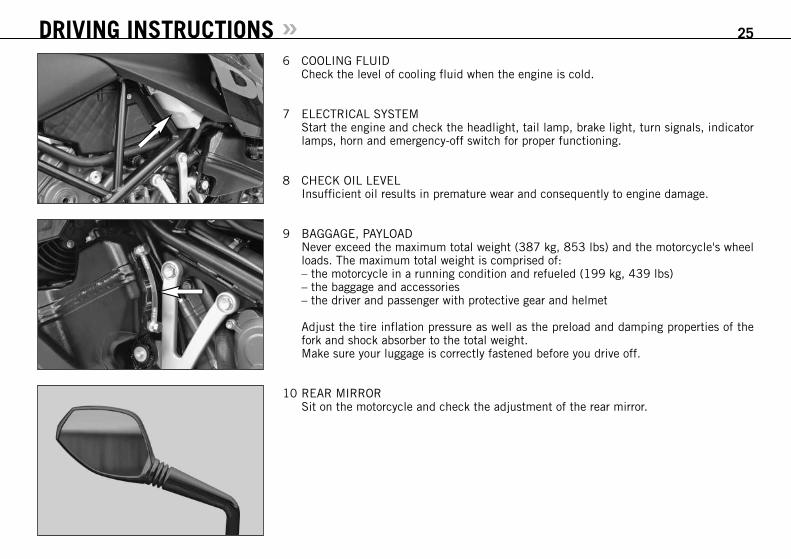
6 COOLING FLUIDCheck the level of cooling fluid when the engine is cold.
7 ELECTRICAL SYSTEMStart the engine and check the headlight, tail lamp, brake light, turn signals, indicatorlamps, horn and emergency-off switch for proper functioning.
8 CHECK OIL LEVELInsufficient oil results in premature wear and consequently to engine damage.
9 BAGGAGE, PAYLOADNever exceed the maximum total weight (387 kg, 853 lbs) and the motorcycle's wheelloads. The maximum total weight is comprised of:– the motorcycle in a running condition and refueled (199 kg, 439 lbs)– the baggage and accessories– the driver and passenger with protective gear and helmet
Adjust the tire inflation pressure as well as the preload and damping properties of thefork and shock absorber to the total weight.Make sure your luggage is correctly fastened before you drive off.
10 REAR MIRRORSit on the motorcycle and check the adjustment of the rear mirror.
DRIVING INSTRUCTIONS » 25

Starting the engine1 Switch on emergency OFF switch [1].2 Switch on ignition (turn ignition key [2] into position ).
NOTE:You will hear the operation of the fuel pump for approx. 2 seconds after switching onthe ignition. The FI indicator lamp will also light up during this time and the engine can-not be started.
3 Switch transmission to idle (green indicator lamp N [3] lights up).4 Do not accelerate; operate starter button [5].
NOTE:If you accelerate during the starting process you will hear a loud, metallicsound caused by the torque limiter. The torque limiter protects thecomponents in the starter drive from being damaged.
5 The oil pressure warning lamp [4] should go out as soon as the engine is running.6 Take the load off the side stand and fold the side stand all the way up.
– Do not start the engine and allow it to idle in a closed room. Exhaust fumes are poison-ous and can cause loss of consciousness and death. Always provide adequate ventila-tion while the engine is running.
– Never operate the motorcycle with a run-down battery or without the battery. This candamage the electronic components or safety equipment in either caseand the motorcy-cle will no longer be roadworthy.
– If you accelerate while starting, the engine management will not inject any fuel and theengine will not start. Do not accelerate while starting!
– If the oil pressure warning lamp does not go out as soon as the engine is running, imme-diately switch off the engine. If the engine is not switched off, engine damage will occurwithin a short period of time. Check the engine oil level or contact a ktm workshop.
– Maximum period for continuous starting: 5 seconds. Wait at least 5 seconds before try-ing again.
– Don’t ride your motorcycle with full load and don’t rev engine when cold. Because thepiston is warming up faster than the water cooled cylinder, it can cause engine damage.Always let the engine warm up before and refrain from driving with full load until theengine is warm.
DRIVING INSTRUCTIONS » 26
1
3
4
2
5

IF THE ENGINE IS DOES NOT CRANK WHENYOU ACTUATE THE STARTER TIP SWITCH:– whether you accelerated while starting – the transmission is switched to idle– Check if the emergency OFF switch is on– Check if the ignition is on– the headlight is on
– If this is not the case, the battery is dis-charged
– If the lights are on, proceed as describedin the „Trouble-shooting“ section orcontact a KTM dealer.
IF THE ENGINE CRANKS BUT DOES NOTSTART, WHEN YOU ACTUATE THE STARTERTIP SWITCH:– whether you accelerated while starting – whether the FI indicator lamp is blinking
– if yes, check Troubleshooting - Blinkcodes table
– Check if sufficient fuel is in the tank– If this is not the case, refill the tank– if sufficient fuel is in the tank, pro-
ceed as described in the „Trouble-shooting“ section or contact a KTMdealer.
NOTE:This motorcycle is equipped with a safety start-ing system. The engine can only be startedif the transmission is in neutral or the clutchlever is pulled. If the side stand is folded down,the engine can only be started if the trans-mission is in neutral or the clutch lever is
pulled. The engine will stall if a gear isengaged and the clutch lever is released withthe side stand folded down.
Starting offPull the clutch lever and engage 1st gear.Slowly release the clutch lever while you gen-tly accelerate.
Do not attach a helmet or other objects tothe helmet lock rope while driving. You caneasily lose control of the motorcycle.
Shifting/RidingYou are now in first gear, refered to as thedrive or uphill gear. Depending on the con-ditions (traffic, road gradient, etc.), you canshift to a higher gear. Close throttle, at thesame time pull clutch lever and shift to thenext higher gear. Let clutch lever go againand carefully open throttle. Do not shift gearsand accelerate carefully in curves.Only accelerate to the extent that road andweather conditions allow. Be especially care-ful when you accelerate in curves. Abruptopening of the throttle can cause the motor-cycle to go out of control and also increasesfuel consumption.By shifting down, use the brakes if neces-sary and close throttle at the same time. Pullclutch lever and shift down to the next gear.
Let clutch lever go slowely and open throt-tle or shift down again.If the engine is killed f.ex. at a crossing, sim-ply pull the clutch lever and start. It is notnecessary to switch the gear to NEUTRAL.Stop immediately if the FI indicator lamp lightsup while driving. The FI indicator lamp willstart blinking as soon as the transmission isin neutral. The rhythm of the blinking lampwill let you determine the two-digit „blinkcode“, e.g.: Blink code 34: FI blinks 3x long, 4x short,pause, Blink code 06: FI blinks 6x short, pause The blink code will indicate which compo-nent is defective (see Troubleshooting). Thismakes it possible to pinpoint the defect if adiagnostic tool is unavailable.
– Avoid abrupt load changes while ridingaround bends and on wet or slipperyground. Otherwise you might easily losecontrol over your motorcycle.
DRIVING INSTRUCTIONS » 27

– While riding your motorcycle, never switchthe ignition lock to positions and .
– Do not try to change the settingsof thecombined instrument while driving. Yourattention will be distracted from the traf-fic and this may cause you to lose con-trol of your motorcycle.
– The frost symbol * in the combined instru-ment will start to blink on icy roads. Adaptyour speed to the road and weather con-ditions.
– The passenger must hold on to the driveror the holding strap on the seat while rid-ing and keep his/her feet on the passen-ger footrests.
– Regularly make sure that the baggageand cases are tightly fastened.
– After falling with the motorcycle, checkall functions thoroughly before starting upoperations again.
– A bent handlebar must always be replaced.Never try to straighten the handlebarbecause this will cause it to lose its sta-bility.
– High rpm rates when the engine is coldhave an adverse effect on the life of yourengine. We recommend you run the enginein a moderate rpm range for a few milesgiving it a chance to warm up. After thatno further precautions in this respectneed be taken. The engine has reachedoperating temperature as soon as the 4th
bar on the temperature indicator lights up.– If the red oil pressure warning lamp lights
up while driving, the oil pressure is toolow to adequately lubricate the engine.Stop immediately and switch off theengine. if you continue to drive, enginedamage will occur within a short periodof time. Check the engine oil level or con-tact an authorized KTM workshop.
– Never have the throttle wide open whenchanging down to a lower gear. The enginewill overspeed, damaging the valves. Inaddition, the rear wheel blocks so that themotorcycle can easily get out of control.
– Never use your motorcycle without an airfilter. Otherwise dust and dirt may enterthe engine and cause increased wear.
– Stop immediately if a perceptible powerloss occurs while driving due to a defec-tive ignition caused by a cylinder misfir-ing or breaking down. If the unburnedfuel/air mixture reaches the catalytic con-verter, it will ignite and the resulting heatwill destroy the catalytic converter and theadjoining components.
– The red coolant warning lamp lights upwhen the coolant temperature has reached120°c (248°F).
Possible causes for the increase in tem-perature:– low driving velocity and high load sit-
uation in high air temperatures– level of coolant in the system is insuf-
ficient– fan at radiator is not running
– improper use of the clutch while drivingat low velocities
Let the engine cool down. Meanwhile,check whether any cooling liquid is leak-ing out of the motorcycle. Check the cool-ing liquid level in the radiator (not onlyin the compensating tank). - CAUTIONSCALDING HAZARD! Do not drive on,until there is sufficient liquid in the col-ing system.
– In the event that, while riding on yourmotorcycle, you notice any unusual oper-ation-related noise, stop immediately,turn the engine off, and contact an author-ized KTM dealer.
BrakingClose throttle and apply the hand and footbrakes at the same time. Carefully apply thebrakes on sandy, wet or slippery surfaces.Always brake with feeling, blocking wheelscan cause you to skid or fall. Also change downto lower gears depending on your speed.Always finish braking before you enter acurve.When driving downhill, use the braking effectof the engine. Change down one or two gearsbut do not overspeed the engine. In this way,you will not need to brake so much and thebrakes will not overheat.
– In the rain, or after the motorcycle hasbeen washed, braking action may bedelayed due to wet brake discs. First, thebrakes must be braked dry.
DRIVING INSTRUCTIONS » 28
DRIVING INSTRUCTIONS » 29
– On salt-sprayed or dirty roads brake actionmay be delayed as well. First, the brakesmust be braked clean.
– Remember that the stopping distancewill be longer if you are carrying a pas-senger or baggage.
– When you brake, the brake discs, brakepads, brake caliper and brake fluid heatup. The hotter these parts get, the weakerthe braking effect. In extreme cases, theentire braking system can fail.
– If the resistance in the hand brake leveror foot brake pedal feels „spongy“ (toomuch play), this is an indication that
something is wrong with the brake sys-tem. Don’t ride your motorcycle anymorewithout first having the brake systemlooked over by a KTM dealer.
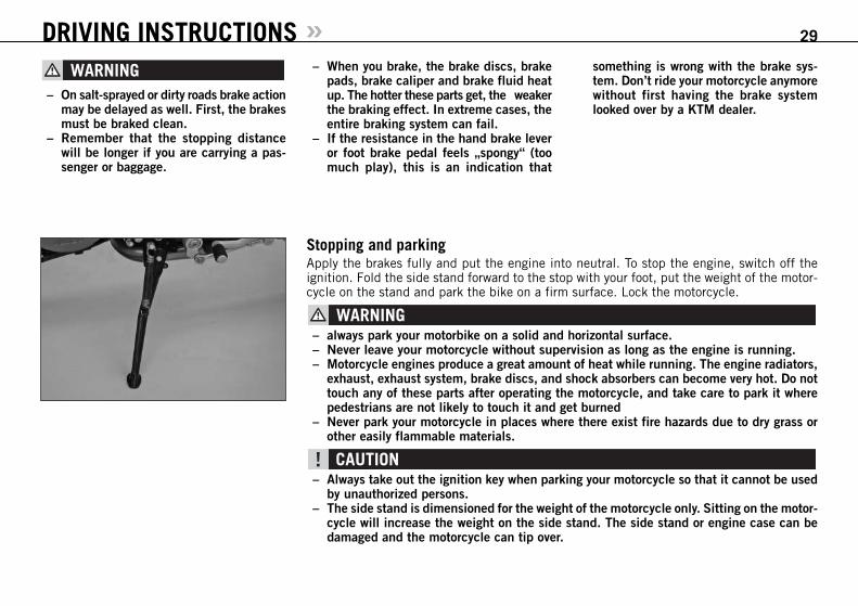
Stopping and parkingApply the brakes fully and put the engine into neutral. To stop the engine, switch off theignition. Fold the side stand forward to the stop with your foot, put the weight of the motor-cycle on the stand and park the bike on a firm surface. Lock the motorcycle.
– always park your motorbike on a solid and horizontal surface.– Never leave your motorcycle without supervision as long as the engine is running.– Motorcycle engines produce a great amount of heat while running. The engine radiators,
exhaust, exhaust system, brake discs, and shock absorbers can become very hot. Do nottouch any of these parts after operating the motorcycle, and take care to park it wherepedestrians are not likely to touch it and get burned
– Never park your motorcycle in places where there exist fire hazards due to dry grass orother easily flammable materials.
– Always take out the ignition key when parking your motorcycle so that it cannot be usedby unauthorized persons.
– The side stand is dimensioned for the weight of the motorcycle only. Sitting on the motor-cycle will increase the weight on the side stand. The side stand or engine case can bedamaged and the motorcycle can tip over.

FuelIn the condition at delivery, the LC8 engine requires unleaded fuel with at least RON 95(USA = Premium PON 91, see technical specifications – engine).After refueling, it will take approx. 3 minutes for the fuel warning lamp to switch off and forTRIP F to automatically reset to 0 and return to the previous display mode.NOTE:Press the SET key for 2 seconds to immediately turn off the fuel warning lamp.
This motorcycle is equipped with a catalytic converter that will be destroyed if you use leadedfuel. Always use unleaded fuel.
Fuel expands when its temperature rises. Therefore do not fill the tank to the top (see fig.).
Gasoline is highly flammable and poisonous. Extreme caution should be used when han-dling gasoline. Do not refuel the motorcycle near open flames or burning cigarettes. Alwaysswitch off the engine before refuelling. Be careful not to spill gasoline on the engine or exhaustpipe while the engine is hot. Wipe up spills promptly. If gasoline is swallowed or splashedin the eyes, seek a doctor’s advice immediately.
DRIVING INSTRUCTIONS » 30
MAX

31
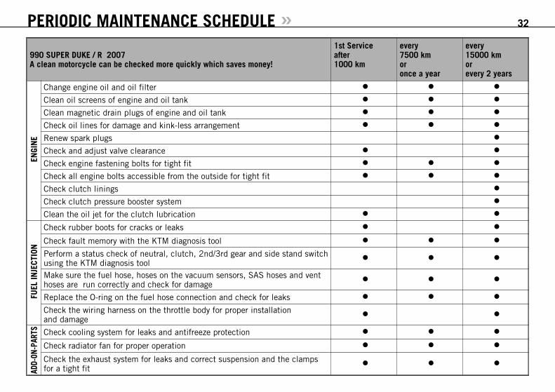
PERIODIC MAINTENANCE SCHEDULE »990 SUPER DUKE / R 2007A clean motorcycle can be checked more quickly which saves money!
1st Service after1000 km
every7500 km or once a year
every15000 km orevery 2 years
ENGI
NE
Change engine oil and oil filter
Clean oil screens of engine and oil tank
Clean magnetic drain plugs of engine and oil tank
Check oil lines for damage and kink-less arrangement
Renew spark plugs
Check and adjust valve clearance
Check engine fastening bolts for tight fit
Check all engine bolts accessible from the outside for tight fit
Check clutch linings
Check clutch pressure booster system
Clean the oil jet for the clutch lubrication
FUEL
INJE
CTIO
N
Check rubber boots for cracks or leaks
Check fault memory with the KTM diagnosis tool
Perform a status check of neutral, clutch, 2nd/3rd gear and side stand switchusing the KTM diagnosis tool Make sure the fuel hose, hoses on the vacuum sensors, SAS hoses and venthoses are run correctly and check for damage
Replace the O-ring on the fuel hose connection and check for leaks
Check the wiring harness on the throttle body for proper installation and damage
ADD-
ON-P
ARTS Check cooling system for leaks and antifreeze protection
Check radiator fan for proper operation
Check the exhaust system for leaks and correct suspension and the clamps for a tight fit
32

PERIODIC MAINTENANCE SCHEDULE »990 SUPER DUKE / R 2007A clean motorcycle can be checked more quickly which saves money!
1st Service after1000 km
every7500 km or once a year
every15000 km orevery 2 years
ADD-
ON-P
ARTS
Replace the graphite gasket in the rear exhaust manifold slide
Check actuating cables for damage, smooth operation, and kink-less arrange-ment,adjust and lubricate
Check the oil level in the hydraulic clutch reservoir
Check air filter, renew if necessary, clean air filter box
Check cables for damage and kink-less arrangement
Check headlamp adjustment
Check electrical system for function (low/high beams, stop light, turn indica-tors,headlamp, flasher, tell-tale lamps, speedometer illumination, horn, side-stand switch, clutch switch, emergency-off switch)
Make sure all bolts and nuts are tight
BRAK
ES
Check brake fluid level, lining thickness, and brake discs
Change brake fluid
Check brake lines for damage and leaks
Check/adjust smooth operation, free travel of handbrake/footbrake levers
Check bolts of brake system for tight fit
CHAS
SIS
Check shock absorber and fork for leaks and proper operation
Clean fork dust sleeves
Bleed fork legs
Check swinging-fork pivot
Check/adjust steering-head bearing
Check all chassis bolts for tight fit (fork plates, fork leg, axle nuts/bolts,swinging-fork pivot, reversing lever, shock absorber)
33

PERIODIC MAINTENANCE SCHEDULE » 34
IF MOTORCYCLE IS USED FOR COMPETITION 7500 KM SERVICE SHOULD BE CARRIED OUT AFTER EVERY RACE!Service intervalls should never be exceeded by more than 500 km.Maintenance work performed by an authorized KTM workshop is not a substitute for care and maintenance by the driver!
990 SUPER DUKE / R 2007A clean motorcycle can be checked more quickly which saves money!
1st Service after1000 km
every7500 km or once a year
every15000 km orevery 2 years
WH
EELS
Check rim joint
Check tire condition and inflation pressure
Check chain, sprockets and chain guides for wear, force fit and tension
Check bolts on pinion and chain sprocket for locking devices and a tight fit
Lubricate chain
Check wheel bearings and jerk damper for play
990 SUPER DUKE / R 2007ADDITIONAL SERVICE WORK TO BE PERFORMED UNDER A SEPARATE ORDER
at leastonce a year
every 15000 kmor every 2 years
Perform complete fork maintenance
Perform complete shock absorber maintenance
Clean and lubricate steering-head bearing and sealing elements
Treat the electrical contacts and switches with contact spray
Treat battery connections with contact grease
Change coolant fluid

PERIODIC MAINTENANCE SCHEDULE »990 SUPER DUKE / R 2007VITAL CHECKS AND CARE PROCEDURES TO CONDUCTED BY THE OWNER OR THE MECHANIC
before each start
after every cleaning
every 1000 km
Check oil level
Check brake fluid level
Check brake pads for wear
Check lighting system for proper operation
Check horn for proper operation
Lubricate actuating cables and nipples
Bleed fork legs
Clean chain
Lubricate chain
Check chain tension
Check tire pressure and wear
Check coolant level
Check fuel lines for leaks
Check all control elements for smooth running
Grease the hand brake lever and clutch lever
Check brake performance
Treat exposed metal components (except for the braking and exhaust system) with wax-based anti-corrosion agents
Treat ignition/steering lock and light switch with contact spray
35

– Do not clean the motorcycle with a power washer otherwise water will get into the bearings, electric socket connectors, etc. – Use special KTM screws with the correct thread length to fasten the spoiler to the tank. Mounting other screws or longer screws could
puncture the tank and cause fuel to leak out.– If you disconnect socket connectors with self-locking nuts, replace them before remounting. If no new self-locking nuts are available,
apply Loctite 243 to the thread of the old nuts. If the thread is damaged, replace the screws and nuts.– Do not use toothed disks or split washers for the engine fastening bolts since they will work their way into the frame components and
become loose. Always use self-locking nuts. – Let the motorcycle cool down before servicing to avoid being burned. – Properly dispose of oils grease, filters, fuel, cleansers, etc. Observe the regulations effective in your country.– Never pour used oil in the sewer or dispose of it outdoors. 1 liter of used oil will pollute 1,000,000 liters of water.
MAINTENANCE WORK ON CHASSIS AND ENGINE » 36


Adjusting the spring preload on the forkThe fork spring preload can be adjusted by turning the adjusting screws [2] (wrench size 24mm) ± 5 mm (0,2 in).Turning in a clockwise direction will increase the preload, turning in a counterclockwise direc-tion will decrease the preload. 1 turn will change the preload by 1 mm.Changing the preload will not affect the rebound damping adjustment, although adjustingscrew [1 will turn at the same time. Make the same spring preload adjustments to both forklegs.Generally, if the preload is higher, the rebound damping should also be set higher.
STANDARD ADJUSTMENT:– Turn adjusting screw counterclockwise as far as it will go.– Turn 5 turns in a clockwise direction.
MAINTENANCE WORK ON CHASSIS AND ENGINE » 38
Compression damping of shock absorberThe shock absorber can synchronize the compression damping in the low and high-speedrange separately (Dual Compression Control).Low and high speed refers to the movement of the shock absorber during compression andnot to the speed of the motorcycle.The low and high-speed technology overlaps.The low-speed setting is primarily for slow to normal shock absorber compression rates.The high-speed setting is effective at fast compression rates.Turning in a clockwise direction will increase the damping, turning counterclockwise willdecrease the damping.
1
2
BASIC SETTINGSHOCK ABSORBER WP 4618 BAVP
Super Duke Super Duke R
Dri
ving
Com
fort
Bas
ic S
etti
ng
Dri
ving
Spo
rt
Max
imum
Pay
load
Bas
ic S
etti
ng
Dri
ving
Spo
rt
Race
cou
rse
Max
imum
Pay
load
Compression adj. Low Speed (clicks) 25 20 10 10 20 16 10 16
Compression adj. High Speed (turns) 2 1.5 1 1 2.5 1.5 1 1,5
Rebound adjuster (clicks) 20 12 8 8 12 12 8 12
Spring preload (mm) 6 6 6 6 5 5 5 5

STANDARD ADJUSTMENT LOW-SPEED:– Turn adjusting screw [1] clockwise as far as it will go.– Turn 20 clicks in a counterclockwise direction.
STANDARD ADJUSTMENT HIGH-SPEED:– Turn adjusting screw (wrench size 17 mm) clockwise as far as it will go.– Super Duke: Turn 1.5 turns in a counterclockwise direction.– Super Duke R: Turn 2.5 turns in a counterclockwise direction.
The damping unit of the shock absorber is filled with high-compression nitrogen. Never tryto take the shock absorber apart or to do anymaintenance work yourself. Severe injuries couldbe the result.Never unscrew the black screw connection (24mm).
Rebound damping of shock absorberBy using the adjusting screw [2], the degree of damping of the rebound can be adjusted.Turn the knob in a clockwise direction to increase damping, turn it in a counterclockwisedirection to reduce damping during rebounding.STANDARD ADJUSTMENT:– Turn adjusting screw [2] clockwise as far as it will go.– Turn 12 clicks in a counterclockwise direction.
The damping unit of the shock absorber is filled with high-compression nitrogen. Never tryto take the shock absorber apart or to do any maintenance work yourself. Severe injuriescould be the result.
MAINTENANCE WORK ON CHASSIS AND ENGINE » 39
1
2
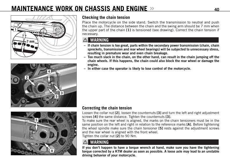
Checking the chain tensionPlace the motorcycle on the side stand. Switch the transmission to neutral and pushthe chain up. The distance between the chain and the swing arm should be 7 mm whenthe upper part of the chain [1] is tensioned (see drawing). Correct the chain tension ifnecessary.
– If chain tension is too great, parts within the secondary power transmission (chain, chainsprockets, transmission and rear wheel bearings) will be subjected to unnecessary stress,resulting in premature wear and even chain breakage.
– Too much slack in the chain, on the other hand, can result in the chain jumping off thechain wheels. If this happens, the chain could also block the rear wheel or damage theengine.
– In either case the operator is likely to lose control of the motorcycle.
MAINTENANCE WORK ON CHASSIS AND ENGINE » 40
Correcting the chain tension Loosen the collar nut [2], loosen the counternuts [3] and turn the left and right adjustmentscrews [4] the same distance. Tighten the counternuts [3]. To make sure the rear wheel is aligned, the marks on the chain tensioners must be in thesame position on the left and right in relation to the reference marks [A]. Before tighteningthe wheel spindle make sure the chain tensioner [5] rests against the adjustment screwsand the rear wheel is aligned with the front wheel. Tighten the collar nut [2] to 90 Nm.
If you don’t happen to have a torque wrench at hand, make sure you have the tighteningtorque corrected by a KTM dealer as soon as possible. A loose axle may lead to an unstabledriving behavior of your motorcycle.
7 mm
1
2
4
53
5
A

Chain maintenanceMaintenance of the X-ring chain is reduced to a minimum. Rinse off any heavy dirt withplenty of water. Residual used grease must be removed prior to lubrication (Motorex ChainClean 611). After drying, use a chain spray specially designed for X-ring chains (MotorexChainlube 622).
– No lubrication is allowed to reach the rear tire or the brake disk, eitherwise the roadadherence and the rear wheel braking effects would be strongly reduced and the motor-cycle could easily get out of control.
– The chain does not have a chain joint for safety reasons. Always have the chain replacedin an authorized KTM workshop where the service technicans have the required rivetingtool.
– Never mount a normal chain joint.
Also check sprockets and chain guides for wear, and replace if necessary.
Checking the chain for wearTo check the chain for wear proceed as follows:Switch the transmission to idle and put a load of approx. 15 kilograms (33 lbs) on the lower part of the chain (see illustration). Now measure the distance between18 chain rollers on the upper part of the chain. The chain needs to be replaced when thedistance is 272 mm (10.70 in). Since chains do not always wear evenly, repeat the meas-urement at different parts of the chain.Replace the chain if any X-rings are missing.
NOTE:If you mount a new chain, the sprockets should also be replaced. New chains wear faster ifused on old used sprockets.
MAINTENANCE WORK ON CHASSIS AND ENGINE » 41
15 KG
max. 272 mm
1 2 3 16 17 18

General information on KTM disk brakes BRAKE CALIPERS: The front brake calipers [1] have 4 brake pistons and are radially bolted to the fork legs.The front brake disks are designed as „floating“ brake disks, i.e. they are not firmly con-nected to the front wheel. The lateral balance ensures that the brake pads always have the best possible contact to the brakedisk. Apply Loctite 243 to the screws [2] on the brake caliper support and tighten to 45 Nm. The rear brake caliper [3] has 1 brake piston and is designed as a „floating brake caliper“,i.e. it is not firmly connected to the brake caliper support. The lateral balance ensures thatthe brake pads always have the best possible contact to the brake disk.
For safety reasons, always have maintenance work and repairs to the brake system performedby an authorized KTM workshop.
BRAKE PADS:Your motorcycle is equipped with sintered brake pads in the front and rear and homologatedaccordingly. They guarantee maximum braking performance.Front brake pads: HAWK 7342-49Rear brake pads: TOSHIBA TTH 38 GF
Brake pads available in the accessory trade are often not authorized for operation of yourKTM motorcycle in road traffic. The brake pads design and friction factor and therefore thebraking power can deviate significantly from original KTM brake pads. If you use differentbrake pads than those provided with the original equipment, it cannot be warranted thatthey are authorized for use in road traffic. Your motorcycle will not longer comply with theregulations authorizing the use of vehicles for road traffic and the warranty will be void.
BRAKE FLUID RESERVOIRS:The brake fluid reservoirs on the front and rear wheel brakes have been designed in such away that even if the brake pads are worn it is not necessary to top up the brake fluid. Thereis no reason to remove the reservoir cap under normal conditions. If the brake fluid leveldrops below the minimum either the brake system has a leak or the brake pads are com-pletely worn down. In this case, consult an authorized KTM dealer immediately.
MAINTENANCE WORK ON CHASSIS AND ENGINE » 42
3
LOCTITE 243
2
1

BRAKE FLUID:We recommend that you use Motorex DOT 5.1 brake fluid when you refill or change the brakefluid. DOT 5. 1 brake fluid has a wet boiling point of 180°C / 356°F (25°C / 45°F higherthan DOT 4) and is safer for high performance applications. Brake fluid DOT 5.1 is a poly-ethylene glycol based fluid, amber-colored and can be mixed with DOT 4 brake fluid. Donot, in any event, use DOT 5 brake fluid. It is based on silicone oil and is dyed purple. KTMmotorcycle gaskets and brake hoses are not designed for DOT 5 brake fluid.Brake fluid is exposed to a high thermal load and absorbs moisture from the air, which low-ers the boiling point. The brake fluid should therefore be changed at the prescribed intervals.
Have the brake fluid for the front and rear brake changed at an authorized KTM workshopevery 2 years.
BRAKE DISCS:Wear reduces the thickness of the brake disc in the area of contact [4] with the brake pads.The brake disk should not be thinner than 4 mm (0.16 in) at the weakest point [A]. Checkthe wear at several points.
Brake disks that are less than 4 mm (0.16 in) thick are a safety hazard. Have worn brakedisks replaced immediately.
MAINTENANCE WORK ON CHASSIS AND ENGINE » 43
A
4

Adjusting the basic position of the hand brake lever The basic position of the hand brake lever can be modified by turning the adjusting screw[1]. This lets you adapt the position of the pressure point (the resistance you feel on thehand brake lever when the brake pads are pressed against the brake disk) to fit any hand.
At the hand brake lever, free travel must at least be 3 mm (0.12 in). Only then may the pis-ton in the hand brake cylinder be moved (to be recognized by the greater resistance of thehand brake lever). If this free travel is not provided, pressure will build up in the brakingsystem, and the front wheel brake may fail due to overheating.
Checking the front brake fluid level The brake fluid reservoir for the front brake is located on the left side of the handlebar andhas a „MIN“ and a „MAX“ mark. The brake fluid level may not fall below the „MIN“ markwhen the vehicle is parked in a vertical position.
– If the brake fluid level drops below the minimum either the brake system has a leak orthe brake pads are completely worn down. In this case, consult an authorized KTM dealerimmediately.
– Have the brake fluid changed at an authorized KTM workshop every 2 years.
MAINTENANCE WORK ON CHASSIS AND ENGINE » 44
min. 3 mm
1

Checking the front brake padsThe brake pads can be inspected from the rear. The linings must be at least 1 mm (0.04in) thick.
At their most worn point brake pad linings should not be thinner than 1 mm, otherwise theycould lead to brake failure. For your own safety don’t put off having your brake pads changed.
If the brake pads are replaced too late when the lining is partly or completely worn off, thesteel parts on the brake pads will grind against the brake disks. This significantly decreasesthe braking effect and destroys the brake disks.
MAINTENANCE WORK ON CHASSIS AND ENGINE » 45
min.1 mm

Checking the rear brake padsThe brake pads can be inspected from the rear. The thickness of the linings may not be lessthan 1 mm (0.04 in).
At their most worn point brake pad linings should not be thinner than 1 mm, otherwise theycould lead to brake failure. For your own safety don’t put off having your brake pads changed.
If the brake pads are replaced too late so that the lining is partly or entirely worn away, thesteel components of the brake pad will rub against the brake disc, imparing the brakingeffect and destroying the brake disc.
MAINTENANCE WORK ON CHASSIS AND ENGINE » 46
Checking the rear brake fluid level The brake fluid reservoir for the rear brake is located on the rear right of the vehicle and hasa "MIN" and a "MAX" mark. The brake fluid level may not fall below the "MIN" mark whenthe vehicle is parked in an upright position.
– If the brake fluid level drops below the minimum either the brake system has a leak orthe brake pads are completely worn down. In this case, consult an authorized KTM dealerimmediately.
– Have the brake fluid changed at an authorized KTM workshop every 2 years.
min.1 mm

47

MAINTENANCE WORK ON CHASSIS AND ENGINE » 48
2
33
2
16
Dismounting and remounting the front wheel Special stands are required to dismount the wheels to make sure the motorcycle is securelyfixed. The front stand only adequately fixes the motorcycle together with the rear stand. Thestands shown in the illustration can be found in the KTM Power Parts catalog.
First mount the rear, then the front stand. Make sure the stands rest on solid ground andare correctly mounted. The front wheel should not touch the ground.
NOTE FOR SUPER DUKE R: First remove the crash pads.
Remove the screws [1] on the left and right brake caliper and carefully pull the brake calipersand bushings [6] off the brake disks towards the back.
Loosen the collar screw [2] and the clamping screws [3] on both fork leg axle passages. Unscrew the collar screw approx 8 turns, press on the collar screw with your hand to pushthe wheel spindle out of the fork leg axle passage and remove the collar screw. Hold thefront wheel while you pull out the wheel spindle. Lift the front wheel off the fork.

MAINTENANCE WORK ON CHASSIS AND ENGINE » 49
4
A
5
B
CC
Take the left [4] and right distance bushing out of the shaft seal rings.
– Do not operate the hand brake when the front wheel has been dismounted.– Be careful not to damage the brake disks when you lay the front wheel down.
Before you remount the front wheel, clean and grease the shaft seal rings [5] and the bear-ing surface [A] of the distance bushings and mount the distance bushings (wide distancebushing in the left shaft seal ring). When mounting the distance bushing, be careful not topress the sealing lips towards the inside. position the front wheel according to the runningdirection shown by the arrows [B] on the rim.
To mount, lift the front wheel in the fork and mount the wheel spindle and collar screw [2].Tighten the collar screw to 60 Nm. Position the brake calipers and bushings [6] and makesure the brake pads are correctly seated. Apply Loctite 243 to the screws [1], mount thescrews and tighten to 45 Nm.Take the motorcycle off the front stand, actuate the front wheel brake and vigorously com-press the fork several times to align the fork legs.
Before you tighten the clamp screws [3] check whether the right brake disk [C] runs in thecenter of the brake caliper. Move the right fork leg to the side if necessary, then tighten theclamp screws on both fork leg axle passages to 15 Nm. Actuate the hand brake until youfeel the pressure point and check whether the front wheel can easily be turned. Remove therear stand.
– If you do not have a torque wrench to mount the wheel, have the torques corrected byan authorized KTM workshop as soon as possible. A loose wheel spindle can cause themotorcycle's handling performance to become instable and cause it to crash.
– After mounting the front wheel, keep operating the hand brake until the pressure pointreturns.
– Always keep the brake disks free from oil and grease, otherwise the braking effect willbe significantly reduced.
NOTE FOR SUPER DUKE R: remount the crash pads.

Dismounting and mounting the rear wheelSpecial stands are required to dismount the wheels to make sure the motorcycle is securelyfixed. The stands shown in the illustration can be found in the KTM Power Parts catalog.
Mount the rear stand. Make sure the stand rests on solid ground and is correctly mounted. The rear wheel should not touch the ground
NOTE FOR SUPER DUKE R: First remove the crash pads.
Unscrew the collar nut [1], remove the chain tensioner [2], hold the rear wheel while youpull out the wheel spindle [3]. Push the rear wheel forward as far as possible and removethe chain from the rear sprocket. Carefully take the rear wheel off the swing arm.
– Do not operate the rear brake when the rear wheel has been dismounted.– Always place the wheel on the ground with the brake disc pointing upwards. Otherwise
the brake disc may be damaged.– If the axle is dismounted, clean the thread of the wheel spindle and collar nut thoroughly
and apply a new coat of grease (Motorex Long Term 2000) to prevent the thread fromjamming.
Before remounting the rear wheel, clean and grease the bearing surface of the bushings [5]and the shaft seal ring [6].
The rear wheel is remounted in the reverse order. Make sure the chain tensioners [4] aremounted in the same way on the left and right. The marks on the chain tensioners must bein the same position on the left and right in relation to the reference marks [A]. Before youtighten the collar nut to 90 Nm, press the rear wheel towards the front to allow the chaintensioner to rest against the clamping screws.
NOTE FOR SUPER DUKE R: remount the crash pads.
MAINTENANCE WORK ON CHASSIS AND ENGINE » 50
2
4
A
3
1

– If you don’t happen to have a torque wrench at hand, make sure you have the tighten-ing torque corrected by a KTM dealer as soon as possible. A loose wheel spindle maylead to an unstable driving behavior of your motorcycle.
– After mounting the rear wheel, keep operating the footbrake until the pressure point returns.– It is very important to keep the brake disk free from oil and grease, otherwise the brak-
ing effect would be strongly reduced.
MAINTENANCE WORK ON CHASSIS AND ENGINE » 51
5
6
Tires, air pressureTire type, tire condition, and how much air pressure the tires have in them affect the wayyour motorcycle rides, and they must therefore be checked whenever you’re getting ready togo anywhere on your motorcycle.
For driving safety and maximum handling, only use tires authorized by KTM (tire releasesare available on the Internet at www.ktm.com) corresponding to the „ZR“ speed index (over240 KPH). Other tires can have a negative effect on the motorcycle's handling (e.g. cancause it to „wobble“ at higher speeds).

BatteryThe battery is located in the front spoiler in front of the engine and is maintenance-free. Itis not necessary to check the electrolyte level or to refill water. Simply keep the battery polesclean and slightly grease them with an acid-free grease if necessary. The charge conditionand type of charge are very important for the battery's service life.
Never operate the motorcycle with a run-down battery or without the battery. This can dam-age the electronic components or safety equipment in either caseand the motorcycle will nolonger be roadworthy.
Never remove the closing cover [1] otherwise the battery will be damaged.
– Tire type and size can be found in the technical specifications and in the homologationcertificate.
– Tire condition has to be checked every time you want to ride your motorcycle. Beforeleaving check for punctures and nails or other sharp objects that might have becomeembedded in the tire.
– Refer to the specific regulations in your country for minimum tire tread requirements.We recommend replacing tires at the latest when the tread is down to 2 mm (0.08 in).
– Tire pressure should be checked regularly on a „cold“ tire. Adapt the air pressure to themotorcycle's total weight. Proper pressure ensures optimum driving comfort and extendsthe life of your tires.
MAINTENANCE WORK ON CHASSIS AND ENGINE » 52
TIRES – AIR PRESSURE
990 Super Duke / R front rear
Road, driver only 2.4 bar34 psi
2.4 bar34 psi
Road, with passenger 2.4 bar34 psi
2.6 bar37 psi
maximum payload 2.4 bar34 psi
2.6 bar37 psi
1
– Do not mount tires which have not beenapproved by KTM. Other tires could haveadverse effects on the way your motorcy-cle rides.
– Use tires of the same brand and type forthe front and rear wheels.
– For your own safety replace damaged tiresimmediately.
– Worn tires can have a negative effect onhow your motorcycle performs, especiallyon wet surfaces.
– If air pressure is too low, abnormal wearand overheating of the tire can result.
– New tires have a smooth surface, whichmeans that they must be run in to achievefull grip. For this purpose, ride the motor-cycle carefully at moderate speed duringthe first 200 kilometers (125 miles) with
new tires, tilting the vehicle at differentangles so that all sections are properlyroughened. Tires will not display their fullgrip characteristics until they are properlyrun in.
– For reasons of safety, it is recommendedto exchange the valve insert whenever anew tire is mounted.

Removing and remounting the battery The battery only needs to be removed if the motorcycle is being immobilized. Remove the screws [1] on both sides, loosen the screws [2] 2 turns and remove the frontspoiler towards the front. Push the cables to the side. Remove the screws [3] and fold thebattery cover [4] down. First disconnect the negative terminal, then the positive terminal from the battery. Makesure the battery terminals are not bent when they are removed. Remove the battery cover and take out the battery. Charge the battery before and after storage. Storage temperature 0 - 35°C (32 - 95°F). When remounting the battery, position it in the battery compartment and mount the batterycover. First connect the cables on the positive terminal, then connect the negative terminalto the battery to avoid a short-circuit. Open the battery cover and fasten with 2 screws. Remountthe front spoiler. Apply Loctite 243 to the screws [1] and tighten to 10 Nm.
– If electrolyte (sulphuric acid) leaks from the battery, proceed with great care. The elec-trolyte can cause severe burns.
– In the case of skin contact rinse thoroughly with water.– In the case of contact with the eyes, thoroughly rinse eyes with water for at least 15 min-
utes. Immediately consult a doctor.– The battery is a closed model but can nevertheless emit explosive gases. Avoid sparks
and open fire near the battery.– Defective batteries must be stored out of the reach of children. Ensure proper disposal
of discarded batteries.– The screws on the underride protection must be secured with loctite 243 to prevent them
from becoming loose.
Never disconnect the battery while the engine is running. This will destroy the rectifier-reg-ulator.
STORAGE:If the motorcycle is being immobilized for longer periods of time, remove and charge thebattery. Storage temperature 0 - 35°C (32 - 95°F), avoid direct sunlight.Charge the battery every 3 months.
MAINTENANCE WORK ON CHASSIS AND ENGINE » 53
2
2
1
3
3
4

MAINTENANCE WORK ON CHASSIS AND ENGINE » 54
VOLT
1
Charging the battery The battery discharges every day, even if it is not used.Always disconnect the battery when charging. Charge the battery as described in the instruc-tions [1] on the battery housing. Do not exceed the amperage and charging time. Quick charg-ing at a high amperage has an adverse effect on the service life.
To charge the battery while mounted, always use the KTM battery charger (Item no.58429074000) to ensure that the electric system is not damaged by excess voltage. Alwaysremove the battery if using other battery chargers! You can also use this charging device totest the off-load voltage and startability of the battery and generator. It is impossible to over-charge the battery with this device.
Charge the battery immediately if it is empty when you start the motorcycle. If left to standin an uncharged condition for a longer period of time, the battery will run down and sulfa-tize, destroying the battery.Recharge the battery every 3 months if it is being stored for a longer period of time.
– Never remove the closure since it will be damaged.– To avoid damage to the on-board electronic system, always disconnect the minus pole
before you charge the battery.– To charge, connect the battery to the battery charger before you switch on the battery
charger. When the battery is charged, switch off the battery charger before you discon-nect the battery.
– Provide adequate ventilation when charging the battery in a closed room; the batteryemits explosive gases when charging.
– Electrolytes will escape through the safety valves if the battery is charged too long or atan excessive voltage or amperage. This will reduce battery capacity.
– Try to avoid quick charges.
Jump startJump starts are not recommended since they can damage the motorcycle's electronic system.

Main fuse The main fuse protects all of the motorcycle's electric power consumers. The main fuse islocated on the left under the front spoiler.
Pull the connector [1] out of the bracket, remove the cap [2] and check the main fuse [3].A spare fuse [4] (30 amperes)is also plugged into the bracket.Always replace blown fuses with an equivalent fuse. Visit an authorized KTM workshop if anew fuse blows again after it is inserted.
Never use a stronger fuse or a repaired fuse. Improper use can destroy the entire electricsystem.
MAINTENANCE WORK ON CHASSIS AND ENGINE » 55
1
2
4
3

Fuses for individual power consumers A fuse box is mounted under the seat containing additional fuses that protect the individ-ual electric power consumers.The power consumers are listed numerically on the cover of the fuse box [1] and allocatedas described below. Spare fuses [2] with 10 and 15 amperes are also found in the fuse box.
NO CONSUMER AMPERES 1 . . . . . . . . . Ignition . . . . . . . . . . . . . . . . . . . . . . . . . . . . . . . . . . . . . . . . . . . . . .102 . . . . . . . . Light (high beam, low beam, parking light) . . . . . . . . . . . . . . . . . . . . .153 . . . . . . . . . Horn, brake light, combined instrument . . . . . . . . . . . . . . . . . . . . . . .104 . . . . . . . . . Fuel pump . . . . . . . . . . . . . . . . . . . . . . . . . . . . . . . . . . . . . . . . . . . .105 . . . . . . . . . Fan . . . . . . . . . . . . . . . . . . . . . . . . . . . . . . . . . . . . . . . . . . . . . . . . .106 . . . . . . . . . Clock . . . . . . . . . . . . . . . . . . . . . . . . . . . . . . . . . . . . . . . . . . . . . . .107 . . . . . . . . . Main relay . . . . . . . . . . . . . . . . . . . . . . . . . . . . . . . . . . . . . . . . . . . .108 . . . . . . . . . ACC1 for attachments (switched with the ignition) . . . . . . . . . . . . . . . .109 . . . . . . . . . ACC2 for attachments (positive supply) . . . . . . . . . . . . . . . . . . . . . . . .1010 . . . . . . . . –SPARE . . . . . Spare fuses . . . . . . . . . . . . . . . . . . . . . . . . . . . . . . . . . . . . . . . .10, 15
Replace a blown fuse only with an equivalent one. If a new fuse that has just been set ingets blown again, you are strongly advised to have it inspected by a KTM dealer.
Under no circumstances is a stronger fuse allowed to be set in or a fuse allowed to be “repaired”.An inexpert treatment could damage the whole electrical installation!
The ACC1 and ACC2 fuses [3] are designed for attachments with a maximum power con-sumption of 10 amperes. The respective connector for this equipment is located in the head-light mask. Ask your authorized KTM workshop for details.
MAINTENANCE WORK ON CHASSIS AND ENGINE » 56
12
3

Replacing the headlight lamp Remove the screws [1] on the left and right and tilt the headlight mask down towards thefront.
Never touch the glass of the bulb with your fingers. The glass of the bulb must remain absolutelyfree from grease. Heat will otherwise cause the grease to evaporate and settle down on thereflector.
BULB FOR HIGH BEAM [A]: Remove the rubber cap [2] and pull off the connector [3]. Detach the retaining clip andremove the bulb. Insert a new bulb, attach the retaining clip, connect the connector and mount the rubbercap.BULB FOR LOW BEAM [B]: Remove the rubber cap [4] and pull off the connector [5]. Detach the retaining clip andremove the bulb. When you insert the new bulb, make sure the tab fits in the corresponding recess in thesocket. Attach the retaining clip, connect the connector to the bulb and mount the rubber cap.
PARKING LIGHT BULB [C]: Loosen the AH screw SW4 [6] and push the right mask spoiler aside. Pull out the bulb socket[7] and pull the light bulb out of the socket.
Mount the light bulb in the reverse order.
MAINTENANCE WORK ON CHASSIS AND ENGINE » 57
1 1
BA
34
2
5
6
C
7
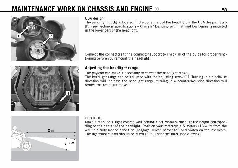
Adjusting the headlight rangeThe payload can make it necessary to correct the headlight range.The headlight range can be adjusted with the adjusting screw [1]. Turning in a clockwisedirection will increase the headlight range, turning in a counterclockwise direction willreduce the headlight range.
CONTROL: Make a mark on a light colored wall behind a horizontal surface, at the height correspon-ding to the center of the headlight. Position your motorcycle 5 meters (16.4 ft) from thewall in a fully loaded condition (baggage, driver, passenger) and switch on the low beam.The light/dark cut-off should be 5 cm (2 in) under the mark (see drawing).
MAINTENANCE WORK ON CHASSIS AND ENGINE » 58
5 m
x 5 cm
1
E F
USA design:The parking light [E] is located in the upper part of the headlight in the USA design. Bulb[F] (see Technical specifications – Chassis / Lighting) with high and low beams is mountedin the lower part of the headlight.
Connect the connectors to the connector support to check all of the bulbs for proper func-tioning before you remount the headlight.

BULB FOR THE TAILLIGHT: Remove the bulb socket [2] from the housing and pull the bulb out of the socket. Insert anew bulb and press the bulb socket all the way into the taillight housing.
Mount the seat.
MAINTENANCE WORK ON CHASSIS AND ENGINE » 59
Replacing the brake light and taillight bulbs NOTE: Only mount red light bulbs in a smoked brake tail light.
Remove the seat.
BULB FOR BRAKE LIGHT: Turn the bulb socket [1] approx. 30° in a counterclockwise direction and pull it out of thetaillight housing. Slightly press in the bulb, turn approx. 30° in a counterclockwise direc-tion and remove it from the socket. Proceed in the reverse order to mount a new bulb.
1
2
3
Replacing the flasher bulbsRemove the screw on the back of the turn signal, carefully fold the lens [3] towards themotorcycle and remove.
Slightly depress the bulb, turn it approx. 30° counterclockwise and pull it out of the socket.
To mount the lamp reverse the worksteps indicated above.

Cooling systemThe water pump in the engine ensures a forced circulation of the cooling liquid. When theengine is cold, the cooling liquid only circulates in the cylinders and cylinder heads. Thethermostat will open when the engine reaches approx. 75°C (167°F) and the cooling liquidwill also be pumped through the aluminum radiator.Cooling is by means of the air stream. The lower the speed, the lower the cooling effect.Soiled cooling fins also impair the cooling effect.If, for example, slow urban traffic or waiting at a traffic light cause little or no air to streamthrough the radiator, the temperature of the cooling liquid will rise. The radiator fan [1] switcheson when the cooling liquid reaches a temperature of 102°C (216°F). Additional air is blownthrough the radiator to prevent the cooling system from overheating.
The temperature indicator [2] will begin to blink and the red cooling liquid temperature warn-ing lamp [3] will light up when the cooling liquid reaches approx. 120°C (248°F), havingexceeded the normal operating temperature. Possible causes:– Slow riding with large loads at a higher air temperature:
If possible increase your running speed, so that more air can blow through the radiators.Should the warning light still be on off after 1500 meters (1 mile), stop immediately,switch off the engine and look for other possible causes.
– The cooling fan on the radiator is not working:The cooling fan must be running, when the cooling liquid temperature is 120°C (248°F)and the ignition is on. If the fan is not working, and there appears to be sufficient cool-ing liquid, the only thing you can do is to drive on to your nearest authorized KTM work-shop at the least possible engine load.
– Too little cooling liquid in the system:Check whether any cooling liquid is leaking out (also on the bottom of the motorcycle).Let the engine cool down and check the cooling liquid level in the radiator (see chapterChecking the cooling liquid level in the radiator). Only continue to drive if there is enoughcooling liquid in the system. Contact an authorized KTM workshop to have the error elim-inated. You will damage the engine if you continue to drive when the cooling liquid tem-perature warning lamp is on.
– Excessive use of the clutch at slow speed
MAINTENANCE WORK ON CHASSIS AND ENGINE » 60
1
3
2

A mixture of 50% antifreeze and 50% distilled water is used as the cooling liquid. How-ever, the anti-freeze protection must be at least -25° C (-13° F). Aside from antifreezing pro-tection, this mixture also provides great corrosion protection which is why it must not bereplaced by pure water.
– For the cooling system, use only high-grade antifreezer (Motorex Anti-Freeze). Usinglowergrade antifreeze agents, can cause corrosion and coolant foaming.
– More antifreeze must be added if you plan to travel to a region where temperatures areexpected to drop below -25°C (-13°F).
Pressure induced by heating of the cooling liquid in the cooling system is controlled by avalve in the radiator cap [4]; a water temperature rising up to 125° C (257° F) is admissi-ble, without fear of problems.Any excess cooling liquid caused by thermal expansion is conducted to the compensatingtank [5]. It will be sucked back in as soon as the temperature in the cooling system drops.
Checking the cooling liquid level in the compensating tankCheck the level of the cooling liquid when the engine is cold. It should fall between the MINand MAX marks on the compensating tank [6].Add cooling liquid (see above for mixture ratio) if the cooling liquid level drops below theMIN mark.If you need to add cooling liquid quite often, the cooling system may leak. If the compen-sating tank is empty, also check the cooling liquid level in the radiator. Have the coolingsystem checked by an authorized KTM workshop.
MAINTENANCE WORK ON CHASSIS AND ENGINE » 61
5
4
6

Checking the cooling liquid level in the radiator Hold the radiator cap [1] with a cloth, carefully turn in a counterclockwise direction andremove. The radiator should be completely filled with cooling liquid; no air should be in theradiator. If any cooling liquid is missing, the cooling system is probably leaking. Have the coolingsystem checked at an authorized KTM workshop.
If possible, check the cooling liquid level when the engine is cold. If you need to removethe radiator cap when the engine is hot, hold the cap with a cloth and open slowly, allow-ing any excess pressure to escape (danger of scalding).
– Accumulated soil and lime on the radiator cap will cause you to lose cooling liquid. Carefullyclean the radiator cap, gasket [2] and sealing area each time.
– If more than 1 liter of cooling liquid needs to be added, you will need to bleed the cool-ing system.
MAINTENANCE WORK ON CHASSIS AND ENGINE » 62
Bleeding the cooling system Take off the left and right spoilers. To take off the spoilers, remove the screws [3] and [4]on each side.
1
33
4
4
2

To completely bleed the cooling system, the motorcycle must be raised approx. 50 cm (20in) in the front. Add cooling liquid until it runs out of the vent holes without bubbles and immediately mountthe screw to prevent air from entering the radiator. Completely fill the radiator with cooling liquid. Mount the radiator cap and move the motor-cycle into a horizontal position again. Now fill the compensating tank [6] with cooling liq-uid until it reaches a level between the MIN and MAX marks. Close the compensating tankand mount both spoilers.
MAINTENANCE WORK ON CHASSIS AND ENGINE » 63
Remove the bleeder screw [5] on the left side of the radiator.
5
6

Adjusting the handlebar tilt Loosen the screws [2]. Adjust the handlebar and tighten the screws to 20 Nm.Make sure the handlebar instruments do not touch the fuel tank when the handlebar is com-pletely turned.
Tilting the handlebar too far back will reduce the steering angle since the handlebar instru-ments will touch the fuel tank
If the handlebar is tilted too far back, the handlebar instruments may damage the fuel tank.
Changing the basic position of the clutch lever The basic position of the clutch lever can be modified by turning the adjusting screw [1].This lets you adjust the best clutch lever position for any hand size. To adjust, pull the clutch lever towards the front. Turning the adjusting screw in a clockwisedirection will move the clutch lever away from the driver. Turning the adjusting screw in acounterclockwise direction will move the clutch lever towards the driver.
Adjustment of the clutch lever position is only possible within certain limits. Only turn theadjusting screw manually and never apply excessive force.
Checking the oil level of the hydraulic clutchThe oil level should be between the „MIN“ and „MAX“ marks with the master cylinder in ahorizontal position.If necessary, add SAE 10 biodegradable hydraulic oil (Motorex clutch fluid 75), availablefrom your authorized KTM workshop.
KTM uses biodegradable, hydraulic mineral oil to actuate the hydraulic clutch. Do not mixthis oil with any other hydraulic oil. Always useoriginal KTM hydraulic oil (available fromyour authorized KTM workshop) to make sure your clutch operates smoothly.Never refill with brake fluid.
MAINTENANCE WORK ON CHASSIS AND ENGINE » 64
1
2

MAINTENANCE WORK ON CHASSIS AND ENGINE » 65
How to change the handlebar position (Super Duke R)The upper triple clamp includes 2 bores arranged at a distance of 15 mm (0.6 in) from oneanother. Accordingly, you can mount the handlebar in 2 different positions.
The steering angle is reduced if the handlebar is mounted in the rear position. Adjust the steering lock so it does not hit the fuel tank.
Adjusting the steering damper (Super Duke R) The steering damper stabilizes the steering whenever the front wheel is relieved or off theground. The damping degree can be adjusted to harder (+) or softer (-) damping by turningthe adjusting knob [1].
BASIC SETTING – Turn the adjusting knob all the way to the stop in a clockwise direction – Turn 20 clicks in a counterclockwise direction
Only change the setting by 3 clicks at a time and take a test ride.
– Always check the steering for smooth operation before starting off on a ride. – Do not try to adjust the steering damper while driving. Your attention will be distracted
from the traffic and this may cause you to lose control of your motorcycle.
1

Engine oilAutomobile engine oil used to be used for four-stroke motorcycles before there were sepa-rate motorcycle specifications. Different technical developments made it necessary to havea separate specification for four-stroke motorcycles - the JASO T903 MA standard. Whereascar engines require long changing intervals, motorcycle engines require a higher power out-put at higher speeds. Most motorcycle engines also use the same oil to lubricate the trans-mission and the clutch. The JASO MA standard responds to these special requirements.Only use fully synthetic engine oils that meet the JASO MA quality requirements (see infor-mation on the can).KTM recommends Motorex Power Synt 4T in the 10W/50 viscosity (for temperatures over0°C, 32°F) or 5W/40 (for temperatures under 0°C, 32°F).
Checking the engine oil level Check the engine oil level when the engine is warm (at least 4 bars on the temperature indi-cator light up). Allow the warm engine to run idle for approx. 1 minute and place the motor-cycle on a level surface (not on the side stand).Wait 20 seconds to allow the oil level in the inspection glass to adjust to the oil level inthe oil tank. The oil level should be between the MIN and MAX marks, add engine oil ifnecessary.
Always check the oil level when the engine is warm. A cold engine can distort the measur-ing results. Engine oil expands when heated, increasing the oil level.
MAINTENANCE WORK ON CHASSIS AND ENGINE » 66
10W/505W/40
JASO T903 MA
TEMPERATUR0°C32°F

Refilling engine oil To refill engine oil, take off the right spoiler [1] by removing the screws [2].
Also remove the screws [3] and take off the spoiler.
Unscrew the plug [4] and refill engine oil. Wait 20 seconds and check the oil level again.The quantity of oil between the MIN and MAX marks is 0.3 liter. Mount the plug and checkthe engine for leaks. Finally, mount the spoilers.
– Insufficient amounts of or low-grade engine oil lead to premature wear in the engine.– Do not overfill the engine case.– Do not underfill the engine case.
MAINTENANCE WORK ON CHASSIS AND ENGINE » 67
2
1
2
3
3
4

Changing the engine oil and the oil filter, cleaning the oil screen
You may only change the engine oil yourself after the warranty period has expired. The war-ranty will become void if you change the oil yourself during the warranty period.
NOTE: The LC8 engine has a dry-sump lubrication system. The engine oil is pumped fromthe oil sump in the engine case to the oil tank. The engine oil must also be drained fromthe oil tank during an oil change. Since many parts must be demounted for an oil change,we recommend having the engine oil changed by an authorized KTM workshop.During the guaranty period, the oil change must be performed by an authorized KTMmechanic. Otherwise, the guarantee will become void.
The engine oil change is to be carried out when the engine is still warm.
An engine having been run warm, and the engine oil in it is very hot – do not burn yourself.
Park the motorcycle on an even surface in an upright position. Place a vessel under theengine to catch the used oil and remove the oil drain plug [1]. Remove the oil drain plug[1], take off the cap [2] and pull the oil sieve out of the engine case with a pair of pliers.
Remove the oil filter cover [3] and pull the oil filter out of the engine case with circlip pli-ers (upside-down).
MAINTENANCE WORK ON CHASSIS AND ENGINE » 68
Remove the screws [4], loosen the screws [5] by 2 turns and remove the front spoiler towardsthe front.
12
3
4
4
5

Remove the drain plug [6] on the oil tank and allow the oil to drain into a receptacle. Removethe screws [7] and tilt the oil return valve [8] to the side.
Carefully pull the oil screen [9] out of the oil tank.
Thoroughly clean the drain plugs, the cover and both oil screens. Clean all rubber seal ringsand check for damage. Replace if necessary.
MAINTENANCE WORK ON CHASSIS AND ENGINE » 69
8
7
76
9

Mount the oil drain plug on the engine with a new seal ring and tighten to 20 Nm.
Slide the oil screen [1] into the guides in the oil pump housing with the TOP mark fac-ing up. Make sure the form ring is in place and mount the cap [2]. Tighten the screws to10 Nm.
Insert a new oil filter [3] in the engine case, grease the O-ring and mount the oil filter covertogether with the O-ring. Tighten the screws to 6 Nm.
Only use original ktm oil filters. The engine can be damaged if other filters are used.
Mount the oil drain plug on the oil tank with a new seal ring and tighten to 20 Nm.
Grease the seal ring [4] and carefully slide the oil screen into the oil tank. Position the oilreturn valve [5], mount the screws and tighten to 10 Nm.
MAINTENANCE WORK ON CHASSIS AND ENGINE » 70
2
1
3
5
4

Remove the right spoiler (see Refilling the engine oil) and unscrew the plug [6]. Add 2.5liters (0.7 USgal) of fully synthetic engine oil meeting the JASO MA standard (e.g. MotorexPower Synt 4T) and remount the plug. Start the engine and allow to run warm in neutraluntil 4 bars on the temperature indicator light up. Switch off the engine and check the oillevel (see Checking the engine oil level).
Check the engine and the oil tank for oil leakage.
Fit the slots in the front spoiler on the lower screws [7] and tighten. Apply Loctite 243 tothe side screws [8] and tighten to 10 Nm.
Finally, mount the spoiler (see Refilling the engine oil).
MAINTENANCE WORK ON CHASSIS AND ENGINE » 71
6
7 8

If you have your motorcycle serviced as set forth in this manual, no malfunctioning is to be expected. Nevertheless, if an error does arise,we recommend that you look for the error according to the following chart.
Please note that you cannot perform all of the work yourself. If you are not sure, contact your KTM dealer.
TROUBLESHOOTING » 72
TROUBLE CAUSE REMEDY
Engine does not start when thestarter button is actuated
Operating error
Discharged battery
Blown fuse
Main fuse is blown
Defect ignition lock or emergencyOFF switch
Defect safe-starting system.
Turn on the ignition, switch the gear to neutral and switch theemergency OFF switch on, do not accelerate while starting theengine.
Recharge the battery and investigate the causes for discharg-ing; contact an authorized KTM workshop.
Replace fuse 1
Remove the front spoiler and replace the main fuse
Check ignition lock and emergency OFF switch, contact anauthorized KTM workshop.
Contact an authorized KTM workshop.
The engine cranks only withpulled clutch lever
A gear is engaged
A gear is engaged and the sidestand is still folded down
Defect safe-starting system.
Shift the transmission to neutral.
Shift the transmission to neutral.
Contact an authorized KTM workshop.
Engine cranks with gearengaged.
Defect safe-starting system. Contact an authorized KTM workshop.

TROUBLESHOOTING »TROUBLE CAUSE REMEDY
Engine cranks but doesn’t start. Operating error
Blown fuse for the fuel pump
Clutch not attached to the fuel line
The plug and socket connector onthe wiring harness is oxidized
Error in the injection system
A gear is engaged and the sidestand is folded down
Pay attention to starting off information(see driving instructions).
Replace fuse 4
Connect the clutch to the fuel line
Remove the panel and fuel tank, clean the plug and socketconnector and spray with contact spray
Visit an authorized KTM workshop
Switch to neutral gear
Engine will not reach full power Air filter/fuel filter heavily soiled
Error in the injection system
Have the air filter/fuel filter replaced at an authorized KTMworkshop
Visit an authorized KTM workshop
Engine overheats Insufficient cooling liquid
Radiator fins are extremely dirty
Foam forms in cooling system
Radiator hose is kinked or damaged
Thermostat defective
Refill cooling liquid (see maintenace work), check cooling sys-tem for leaks
Clean radiator with water jet
Replace cooling liquid, use antifreezer with brand name
Run the radiator hose correctly or replace
Have the thermostat checked (opening temperature 75°C,167°F) or replaced; contact an authorized KTM workshop
73

TROUBLESHOOTING » 74
TROUBLE CAUSE REMEDY
Engine overheats Blown fan fuse
Defect fan or thermoswitch for fan
Air in the cooling system
Replace fuse 5
Contact an authorized KTM workshop.
Bleed the cooling system (see Maintenance work)
FI lamp is blinking / lights up Error in the injection system Visit an authorized KTM workshop
Engine stalls while driving No fuel
Fuse for fuel pump has blown
Refuel
Replace fuse 4
High oil consumption Engine oil level too high
Engine oil too thin (viscosity)
Check engine oil level when the engine is warm; correct ifnecessary
Use thicker engine oil; see chapter „Engine oil“
Headlight and position light fail Blown fuse Replace fuse 2
Flasher lights, brake light, hornand combined instrument fail
Sicherung durchgeschmolzen Replace fuse 3
Time is not displayed or not cor-rectly displayed
Blown fuse, thus no continuouspower supply
Replace fuse 6 and set the clock.

TROUBLESHOOTING »TROUBLE CAUSE REMEDY
The battery is discharged The ignition (power consumer) has-n’t been switched off
The battery isn’t charged by thegenerator
Recharge the battery according to the relevant instructions.
Voltage regulator and generator should be checked by anauthorized KTM workshop.
No values are visible in the com-bined instrument display.
Blown fuse Replace fuse 3
The speed indication on thecombined instrument is notworking
Pickup cable is damaged or con-tacts on the cable connector haveoxidized
Check the pickup cable for damage, visit an authorized KTMworkshop
The blink code indicates which component is affected by an error. This allows the error to be identified if no diagnosis tool is available.
BLINK CODE SIGNAL / COMPONENT ERROR DESCRIPTION ENGINE
02 Pulse generator Malfunction Stalls
06 Throttle sensor Output signal too low /high Continues to run
07 Sensor for 2nd throttle valve Output signal too low /high Continues to run
09 Intake manifold air pressure for sensor rear cylinder Output signal too low /high Continues to run
11 Intake manifold air pressure sensor for front cylinder Output signal too low /high Continues to run
75

TROUBLESHOOTING » 76
BLINK CODE SIGNAL / COMPONENT ERROR DESCRIPTION ENGINE
12 Coolant temperature sensor Output signal too low /high Continues to run
13 Air temperature sensor Output signal too low /high Continues to run
14 Ambient air pressure sensor Output signal too low /high Continues to run
15 Tilt angle sensor Output signal too low /high Continues to run
17 Lambda probe for rear cylinder Malfunction Continues to run
18 Lambda probe for front cylinder Malfunction Continues to run
24 Control unit voltage supply Malfunction Continues to run
25 Side stand switch Short circuit to ground Continues to run
33 Injection nozzle for rear cylinder Malfunction Stalls
34 Injection nozzle for front cylinder Malfunction Stalls
37 Ignition coil for rear cylinder Malfunction Stalls
38 Injection coil for front Malfunction Stalls
41 Fuel pump relay Short circuit to ground / positive Stalls
45 Lambda probe heater for rear cylinder Short circuit to ground / positive Continues to run
46 Lambda probe heater for front cylinder Short circuit to ground / positive Continues to run
49 Idle control motor Malfunction Continues to run
53 Purge valve for carbon canister Short circuit to ground / positive Continues to run
54 Secondary air valve Short circuit to ground / positive or interruption Continues to run
65 EEPROM error Malfunction Continues to run
68 Vacuum hose for front cylinder is defective Malfunction Continues to run
69 Vacuum hose for rear cylinder is defective Malfunction Continues to run
72 Stepper motor for 2nd throttle valve Malfunction Continues to run
The blink code indicates which component is affected by an error. This allows the error to be identified if no diagnosis tool is available.

CLEANING » 77
Regular cleaning and paintwork care are part of the maintenance work and help to maintain the value of your motorcycle.
Never clean the motorcycle with a power washer or a strong water jet, otherwise the pressure will allow water to enter the electric compo-nents, plugs, cables, bearings, etc. which can cause malfunctioning or can lead to premature wear of these components.
– Before you wash your motorcycle, close the muffler openings.– Use warm water with a commercial detergent and sponge. Coarse dirt can be removed with a soft water jet. Areas that are heavily soiled
can be sprayed with a motorcycle cleaner (e.g. Motorex 900) and cleaned with a brush.– After the motorcycle has been rinsed with a soft water jet, it should be dried by air pressure and a cloth. Then take a short drive until
the engine has reached the working temperature and also use the brakes. Due to the heat, the water also evaporates at the unapproach-able parts of the engine and the brakes.
– After the motorcycle has cooled down, oil or lubricate all of the friction bearings and bearing positions and treat the chain with chainspray. Treat all bare areas (except brake disks) with a corrosion inhibitor (e.g. Motorex Protect & Shine).
– The exhaust pipes and mufflers are made of stainless steel and should be treated with a suitable care product.– To prevent failures in the electric system, you should treat the ignition lock, the emergency OFF switch, light switch and the socket con-
nectors with contact spray.– Treat all of the painted parts with a mild paint care product (e.g. Motorex Moto Polish).
CONSERVATION FOR WINTER OPERATION »In the event that the motorcycle is also used in winter and on roads where one has to expect salt spraying, you will have to take precautions against the aggressive road salt.– clean motorcycle thoroughly and let it dry– treat engine, swing arm, and all other bare parts (except for brake discs) with a wax-based anti-corrosion agent.
Keep anti-corrosion agent from getting into contact with the brake discs, for otherwise this will significantly reduce the braking power.
After rides on salted roads, clean motorcycle thoroughly with cold water and let it dry well!

STORAGE » 78
If you plan to immobilize your motorcycle for a longer period of time, proceed as follows:– Run the tank empty to be able to add fresh fuel when starting up again. – Clean the motorcycle thoroughly (see CLEANING chapter). – Change the engine oil and the oil filter (old engine oil contains aggressive impurities). – Check the quantity of antifreeze and cooling liquid. – Remove and charge the battery (see Charging the battery chapter). – If possible, jack up the motorcycle to lift the wheels off the ground. – The storage site should be dry and not subject to larger temperature fluctuations. – Cover the motorcycle with a permeable cover or blanket. Do not use impermeable material since it will not allow and moisture to escape
and will cause corrosion.
Do not briefly run the engine of an immobilized motorcycle since the engine will not become warm enough and any vapor produced duringthe combustion process will condense and cause the valves and exhaust to rust.
STARTING UP AFTER IMMOBILIZATION – Mount the charged battery (pay attention to the polarity) and set the clock. – Fill fresh fuel in the tank. – Inspect the motorcycle as you would before each start-up (see „Driving Instructions“). – Go on a short, cautious test ride
NOTE: before you store your motorcycle at the end of the season, check all parts for proper functioning and wear. If service, repairs or con-versions are necessary, have them carried out while the motorcycle is immobilized (workshops are not fully utilized). This will help to avoidlong waiting periods at the beginning of the season.

TECHNICAL SPECIFICATIONS – CHASSIS »CHASSIS 990 SUPER DUKE / R 2007
Frame Tubular chrome-molybdenum-steel space frame
Fork WP Suspension – Up Side Down 4860 ROMA
Spring travel front 135 mm (5.3 in)
Rear suspension WP Suspension 4618 BAVP
Spring travel rear Super Duke: 160 mm (6.3 in) Super Duke R: 150 mm (5.9 in)
Front brake Disk brake, 2 perforated brake disks Ø 320 mm (12.6 in), brake calipers radially bolted
Rear brake Disk brake, perforated brake disk Ø 240 mm (9.4 in), floating brake caliper
Authorized front tires * DUNLOP Sportmax D208 RR 120/70 ZR17 M/C 58W
Air pressure front Road, driver only...............................................2.4 barRoad, with passenger / maximum payload ...........2.4 bar
Authorized rear tires * DUNLOP Sportmax D208 RR 180/55 ZR17 M/C 73W
Air pressure rear Road, driver only...............................................2.4 barRoad, with passenger / maximum payload ...........2.6 bar
Fuel tank capacity 18.5 liters (4.9 USgal), 3.5 (0.9 USgal) liters Reserve
Gear ratio – rear wheel 17:38
Chain 5/8 x 5/16” X-ring
Lighting high beam ............................................H3 12V 55W (socket PK22s)low beam ..............................................H7 12V 55W (socket PX26d)USA: high beam + low beam ..................H4 12V 60/55 W (socket P43t)position light front ..................................12V 5W (socket W2,1x9,5d)indicator lamps .....................................LEDposition light rear ...................................12V WR5W (socket W2,1x9,5d) ......Super Duke R: LEDUSA: position light rear ...........................12V 5W (socket W2,1x9,5d) ..........Super Duke R: LEDstoplight ...............................................12V PR21W (socket BAW15s) ........Super Duke R: LEDUSA: stoplight .......................................12V 21W (socket BA15s) ..............Super Duke R: LEDflashers .................................................12V RY10W (socket BAU15s)licens plate illumination .........................12V 5W (socket W2,1x9,5d)
* further tire releases are available on the Internet at www.ktm.com
79

TECHNICAL SPECIFICATIONS – CHASSIS »CHASSIS 990 SUPER DUKE / R 2007
Battery maintenance-free battery 12V 11.2 Ah
Steering head angle Super Duke: 66.1° Super Duke R: 67.3°
Wheel base 1450 ± 10 mm (57 ± 0.4 in)
Seat height, unloaded Super Duke: 850 mm (33.5 in) Super Duke R: 860 mm (33.9 in)
Ground clearance, unloaded Super Duke: 140 mm (5.5 in) Super Duke R: 150 mm (5.9 in)
Dry weight 186 kg (410.6 lbs)
Max. axle load front 180 kg (397.3 lbs)
Max. axle load rear 250 kg (551.8 lbs)
Max. total load 387 kg (854.2 lbs)
BASIC SETTINGFORK WP 4860 ROMA
Super Duke Super Duke R
Dri
ving
Com
fort
Bas
ic S
etti
ng
Dri
ving
Spo
rt
Max
imum
Pay
load
Bas
ic S
etti
ng
Dri
ving
Spo
rt
Rac
e co
urse
Max
imum
Pay
load
Compression adjuster (clicks) 20 15 10 10 18 18 14 18
Rebound adjuster (clicks) 20 15 10 10 16 16 12 16
Spring preload (turns) 5 5 5 5 5 5 5 5
Spring 9.5 N/mm 9.5 N/mm
Air chamber length 110 mm (4.3 in)
Fork oil SAE 5 (WP 4860.0401)
BASIC SETTINGSHOCK ABSORBER WP 4618 BAVP
Super Duke Super Duke R
Dri
ving
Com
fort
Bas
ic S
etti
ng
Dri
ving
Spo
rt
Max
imum
Pay
load
Bas
ic S
etti
ng
Dri
ving
Spo
rt
Rac
e co
urse
Max
imum
Pay
load
Compression adj. Low Speed (clicks) 25 20 10 10 20 16 10 16
Compression adj. High Speed (turns) 2 1.5 1 1 2.51.5 1 1.5
Rebound adjuster (clicks) 20 12 8 8 12 12 8 12
Spring preload (mm) 6 6 6 6 5 5 5 5
Spring 170/185 180/185
80

TIGHTENING TORQUES – CHASSIS 2007
Collar bolt on front wheel spindle M24x1.5 60 Nm
Collar nut wheel spindle rear M25x1.5 90 Nm
AH bolt shock absorber top/bottom M14x1.5 80 Nm
Collar nut for swing arm bolt M19x1.5 130 Nm
AH bolts on subframe M8 Loctite 243 + 25 Nm
AH bolts on back of footrest support M8 Loctite 243 + 25 Nm
Engine carrier bolts M10 45 Nm
HH clamp bolts on top triple clamp M8 12 Nm
HH clamp bolts on bottom triple clamp M8 15 Nm
HH screw for steering head M20x1.5 12 Nm
HH clamp bolts on fork leg axle passages M8 15 Nm
Collar bolts for handlebar clamps M8 20 Nm
AH bolt for handlebar mount M10 20 Nm
HH clamp bolts for steering stem M8 20 Nm
Collar bolt front/rear brake disk M8x1.25 Loctite 243 + 30 Nm
HH bolts on front brake caliper M10x1.25 Loctite 243 + 45 Nm
HH bolts on handbrake cylinder M6 10 Nm
HH bolts on footbrake cylinder M6 Loctite 243 + 10 Nm
AH bearing bolt for foot brake pedal, shift lever M8 Loctite 243 + 25 Nm
HH screw on cover plate for foot brake lever/shift mechanism M6 Loctite 243 + 10 Nm
Relay for shift shaft (on connecting support) M8 Loctite 243 + 25 Nm
Relay for shift shaft (on shift shaft) M6 Loctite 243 + 18 Nm
Gearshift rod attachment M6 Loctite 243 + 12 Nm
HH bolts on foot brake pedal surface M5 Loctite 243 + 6 Nm
AH bolts for side stand bracket - engine M10 Loctite 243 + 45 Nm
TECHNICAL SPECIFICATIONS – CHASSIS » 81

TECHNICAL SPECIFICATIONS – CHASSIS »TIGHTENING TORQUES – CHASSIS 2007
HH bolts for side stand fixture - side stand bracket M10 Loctite 243 + 25 Nm
HH bolts for side stand mounting M10 Loctite 243 + 35 Nm
HH bolt for spring rest on side stand M8 Loctite 243 + 25 Nm
HH bolt for side stand switch M4 Loctite 243 + 2 Nm
Drain plug on oil tank M12x1.5 25 Nm
Exhaust nuts on manifold M8 evenly, do not bend sheet metal
Exhaust clamps M8 8 Nm
Exhaust clamps for ball joint M8 35 Nm
AH bolts on tank cover M5 5 Nm
HH bolts on tank mounting M6 6 Nm
Collar screws for in-tank pump M6 6 Nm
AH screw on arm for tank support M10 15 Nm
Collar screw for gas pressure shock absorber M6 6 Nm
Seat fixing plate M5 4 Nm
HH nut for seat lock M19x1 8 Nm
Jerk damper bolt - rear wheel M10x1.25 Loctite 243 + 50 Nm
Chainguard M5 5 Nm
Chain sliding guard M5 5 Nm
Front spoiler M6 Loctite 243 + 10 Nm
Taillight M6 8 Nm
Other bolts on chassis M6M8M10
10 Nm25 Nm45 Nm
Other collar nuts on chassis M6M8M10
15 Nm30 Nm50 Nm
82

TECHNICAL SPECIFICATIONS – ENGINE »ENGINE 990 LC8 2007
Design Liquid-cooled, 2-cylinder 4-stroke engine with 75° V arrangement with balancer shaft and electric starter
Displacement 999 cc
Bore / Stroke 101/62.4 mm
Compression ratio 11.5:1
Fuel unleaded fuel with at least RON 95 (USA: Premium RON 91) *
Valve timing 4 valves controlled over bucket tappet and 2 camshafts, camshaft drive with gears/chain
Valve diameter Intake: 38 mm Exhaust: 33 mm
Valve clearance, cold Intake: 0.10 - 0.15 mm Exhaust: 0.25 - 0.30 mm
Crankcase bearing Friction bearings (2 main bearings / 1 supporting bearing)
Conrod bearing Friction bearing
Piston pin bearing Dual-fuel bearing
Piston Light alloy – forged
Piston rings 1 compression ring, 1 taper face ring, 1 single-piece oil scraper ring with spiral-type expander
Engine lubrication Dry sump with 2 trochoidal pumps (pressure pump and suction pump)
Engine oil SAE 10W-50 (Motorex Power Synt 4T) #
Quantity of engine oil approx. 3 liters (0.8 USgal) during oil/filter change
Primary drive Straight-toothed spur wheels 35 : 67
Clutch Multi-disc clutch in oil bath
Transmission 6-speed claw shifted
Gear ratio 1st gear 14:362nd gear 16:303rd gear 20:304th gear 21:275th gear 23:266th gear 25:26
83

TECHNICAL SPECIFICATIONS – ENGINE »ENGINE 990 LC8 2007
Ignition system breakerless transistorized electronic ignition system with digital ignition advance
Ignition timing Map-controlled via TPS
Map-controlled via TPS 12V 450W at 6000 rpm
Spark plug NGK IR KR8BI
Electrode distance 0.8 mm
Cooling system liquid cooled, permanent circulation of cooling liquid through water pump
Cooling liquid 2.1 liters (0.55 USgal), 50% antifreeze, 50% distilled water, at least –25° C
Starting aid electric starter
10W/505W/40
JASO T903 MA
TEMPERATUR0°C32°F
# PON / CLC RON / ROZ MON
87 91 83
91 Premium 95 87
PON = Pump Octane NumberCLC = Cost of Living CouncilRON = Research Octane NumberROZ = Research Oktan ZahlMON = Motor Octane Number
*
Engine oilOnly use fully synthetic engine oils that meet the JASOMA quality requirements (see information on the can).
KTM recommends Motorex Power Synt 4T in the 10W/50viscosity (for temperatures over 0°C, 32°F) or 5W/40(for temperatures under 0°C, 32°F).
84

Accessories and payload . . . . . . . . . . . . . . . . . . . . . . . . . . . .23Adjusting compression damping of fork . . . . . . . . . . . . . . . . .37Adjusting rebound damping of fork . . . . . . . . . . . . . . . . . . . .37Adjusting the basic position of the hand brake lever . . . . . . . .44Adjusting the fork and shock absorber . . . . . . . . . . . . . . . . .37Adjusting the handlebar tilt . . . . . . . . . . . . . . . . . . . . . . . . .64Adjusting the headlight range . . . . . . . . . . . . . . . . . . . . . . . .58Adjusting the spring preload on the fork . . . . . . . . . . . . . . . . .38Adjusting the steering damper (Super Duke R) . . . . . . . . . . .65Baggage loops . . . . . . . . . . . . . . . . . . . . . . . . . . . . . . . . . .16Battery . . . . . . . . . . . . . . . . . . . . . . . . . . . . . . . . . . . . . . . .52Bleeding the cooling system . . . . . . . . . . . . . . . . . . . . . . . .62Braking . . . . . . . . . . . . . . . . . . . . . . . . . . . . . . . . . . . . . . . .28Chain maintenance . . . . . . . . . . . . . . . . . . . . . . . . . . . . . . .41Changing the basic position of the clutch lever . . . . . . . . . . .64Changing the engine oil and the oil filter, cleaning the oil screen . . . . . . . . . . . . . . . . . . . . . . . . . . . . .68Charging the battery . . . . . . . . . . . . . . . . . . . . . . . . . . . . . .54Chassis number, Type label . . . . . . . . . . . . . . . . . . . . . . . . . . .6Check the following before each start . . . . . . . . . . . . . . . . . .24Checking the chain for wear . . . . . . . . . . . . . . . . . . . . . . . . .41Checking the chain tension . . . . . . . . . . . . . . . . . . . . . . . . . .40Checking the cooling liquid level in the compensating tank . . .61Checking the cooling liquid level in the radiator . . . . . . . . . . .62Checking the engine oil level . . . . . . . . . . . . . . . . . . . . . . . .66Checking the front brake fluid level . . . . . . . . . . . . . . . . . . .44Checking the front brake pads . . . . . . . . . . . . . . . . . . . . . . . .45Checking the oil level of the hydraulic clutch . . . . . . . . . . . . .64Checking the rear brake fluid level . . . . . . . . . . . . . . . . . . . .46Checking the rear brake pads . . . . . . . . . . . . . . . . . . . . . . . .46
Cleaning . . . . . . . . . . . . . . . . . . . . . . . . . . . . . . . . . . . . . . .77Clutch lever . . . . . . . . . . . . . . . . . . . . . . . . . . . . . . . . . . . . .7Combination switch . . . . . . . . . . . . . . . . . . . . . . . . . . . . . . .14Combined instrument . . . . . . . . . . . . . . . . . . . . . . . . . . . . . .8Combined instrument display . . . . . . . . . . . . . . . . . . . . . . . . .8Compression damping of fork . . . . . . . . . . . . . . . . . . . . . . . .19Compression damping of shock absorber . . . . . . . . . . . . . . . .38Conservation for winter operation . . . . . . . . . . . . . . . . . . . . .77Consumer information for USA only . . . . . . . . . . . . . . . . . . . .87Cooling liquid temperature display . . . . . . . . . . . . . . . . . . . .12Cooling system . . . . . . . . . . . . . . . . . . . . . . . . . . . . . . . . . .60Correcting the chain tension . . . . . . . . . . . . . . . . . . . . . . . .40Damping action during compression of shock absorber . . . . . .20Dismounting and mounting the rear wheel . . . . . . . . . . . . . . .50Dismounting and remounting the front wheel . . . . . . . . . . . .48Driving instructions . . . . . . . . . . . . . . . . . . . . . . . . . . . . . . .24Engine number, engine type . . . . . . . . . . . . . . . . . . . . . . . . . .6Engine oil . . . . . . . . . . . . . . . . . . . . . . . . . . . . . . . . . . . . . .84Engine oil . . . . . . . . . . . . . . . . . . . . . . . . . . . . . . . . . . . . . .66Filler cap . . . . . . . . . . . . . . . . . . . . . . . . . . . . . . . . . . . . . .15Foot brake pedal . . . . . . . . . . . . . . . . . . . . . . . . . . . . . . . . .18Footrests . . . . . . . . . . . . . . . . . . . . . . . . . . . . . . . . . . . . . . .19Fuel . . . . . . . . . . . . . . . . . . . . . . . . . . . . . . . . . . . . . . . . . .30Function buttons on combined instrument . . . . . . . . . . . . . . .8Fuses for individual power consumers . . . . . . . . . . . . . . . . . .56General information on KTM disk brakes . . . . . . . . . . . . . . . .42General tips and warnings for starting the motorcycle . . . . . . .22Hand brake lever . . . . . . . . . . . . . . . . . . . . . . . . . . . . . . . . . .7Helmet lock . . . . . . . . . . . . . . . . . . . . . . . . . . . . . . . . . . . .17Holding strap . . . . . . . . . . . . . . . . . . . . . . . . . . . . . . . . . . .17
HEAD WORD INDEX » 85

How to change the handlebar position (Super Duke R) . . . . . .65Ignition lock . . . . . . . . . . . . . . . . . . . . . . . . . . . . . . . . . . . .14Important information . . . . . . . . . . . . . . . . . . . . . . . . . . . . . .2Index . . . . . . . . . . . . . . . . . . . . . . . . . . . . . . . . . . . . . . . . . .4Indicator lamps . . . . . . . . . . . . . . . . . . . . . . . . . . . . . . . . . .13Instructions for initial operation . . . . . . . . . . . . . . . . . . . . . .22Introduction . . . . . . . . . . . . . . . . . . . . . . . . . . . . . . . . . . . . .1Jump start . . . . . . . . . . . . . . . . . . . . . . . . . . . . . . . . . . . . .54Main fuse . . . . . . . . . . . . . . . . . . . . . . . . . . . . . . . . . . . . .55Maintenance work on chassis and engine . . . . . . . . . . . . . . . .36Operation instruments . . . . . . . . . . . . . . . . . . . . . . . . . . . . . .7Periodic maintenance schedule . . . . . . . . . . . . . . . . . . . . . . .32Rebound damping of fork . . . . . . . . . . . . . . . . . . . . . . . . . . .19Rebound damping of shock absorber . . . . . . . . . . . . . . . . . . .39Rebound damping of shock absorber . . . . . . . . . . . . . . . . . . .21Refilling engine oil . . . . . . . . . . . . . . . . . . . . . . . . . . . . . . .67Removing and remounting the battery . . . . . . . . . . . . . . . . .53Replacing the brake light and taillight bulbs . . . . . . . . . . . . .59Replacing the flasher bulbs . . . . . . . . . . . . . . . . . . . . . . . . .59Replacing the headlight lamp . . . . . . . . . . . . . . . . . . . . . . .57Running in the LC8 engine . . . . . . . . . . . . . . . . . . . . . . . . . .22Seat lock, removing the seat . . . . . . . . . . . . . . . . . . . . . . . .16Serial number locations . . . . . . . . . . . . . . . . . . . . . . . . . . . . .6Shift lever . . . . . . . . . . . . . . . . . . . . . . . . . . . . . . . . . . . . . .18Shifting/Riding . . . . . . . . . . . . . . . . . . . . . . . . . . . . . . . . . .27Side stand . . . . . . . . . . . . . . . . . . . . . . . . . . . . . . . . . . . . .18Spring preload of the fork . . . . . . . . . . . . . . . . . . . . . . . . . . .20Starter tip switch, Emergency OFF tip switch . . . . . . . . . . . . .15Starting off . . . . . . . . . . . . . . . . . . . . . . . . . . . . . . . . . . . . .27Starting the engine . . . . . . . . . . . . . . . . . . . . . . . . . . . . . . .26
Starting up after immobilization . . . . . . . . . . . . . . . . . . . . . .78Stopping and parking . . . . . . . . . . . . . . . . . . . . . . . . . . . . . .29Storage . . . . . . . . . . . . . . . . . . . . . . . . . . . . . . . . . . . . . . . .78Tachometer . . . . . . . . . . . . . . . . . . . . . . . . . . . . . . . . . . . . .12Technical specifications – chassis . . . . . . . . . . . . . . . . . . . . .79Technical specifications – engine . . . . . . . . . . . . . . . . . . . . .83Tires, air pressure . . . . . . . . . . . . . . . . . . . . . . . . . . . . . . . .51Tool set . . . . . . . . . . . . . . . . . . . . . . . . . . . . . . . . . . . . . . .17Troubleshooting . . . . . . . . . . . . . . . . . . . . . . . . . . . . . . . . . .72
HEAD WORD INDEX » 86

CONSUMER INFORMATION FOR USA ONLY » 87
REPORTING SAFETY DEFECTSIf you believe that your vehicle has a defect which could cause an accident resulting in injury or death, you should immediately inform the National Highway Traffic SafetyAdministration (NHTSA) in addition to notifying KTM North America, Inc. If NHTSA receives similar complaints, it may open an investigation, and if it finds that a safety defect exists in a group of vehicles, it may order a recall and remady cam-paign. However, NHTSA cannot become involved in individual problems between you, your dealer, or KTM North America, Inc. To contact NHTSA, you may either call the Auto Safety Hotline toll-free at 1–800–424–9393 or visit the website www.nhtsa.dot.gov , or write to: NHTSA, U.S. Department ofTransportation, 400 7th Street, Southwest, Washington, D.C. 20590. You can also obtain other information about motor vehicle safety from the Hotline.
NOISE EMISSION WARRANTYKTM Sportmotorcycle AG warrants that this exhaust system, at the time of sale, meets all applicable U.S. EPA Federal noise standards. This warranty extends to the first per-son who buys this exhaust system for purposes other than resale, and to all subsequent buyers. Warranty claims should be directed to: KTM North America, Inc. 1119 Milan Avenue, Amherst, Ohio 44001, Telephone: (440) 9853553
TAMPERING WARNINGTAMPERING WITH NOISE CONTROL SYSTEM PROHIBITED. FEDERAL LAW PROHIBITS THE FOLLOWING ACTS OR CAUSING THEREOF:1) The removal or rendering inoperative by any person other than for purposes of maintenance, repair, or replacement, of any device or element of design incorporated into
any new vehicle for the purpose of noise control prior to its sale or delivery to the ultimate purchaser or while it is in use, or2) The use of the vehicle after such device or element of design has been removed or rendered inoperative by any person.
AMONG THOSE ACTS PRESUMED TO CONSTITUTE TAMPERING ARE THE ACTS LISTED BELOW.1) Removal of, or puncturing the muffler, baffles, header pipes or any other components which conducts exhaust gases.2) Removal or puncturing of any part of the intake system.3) Lack of proper maintenance.4) Replacing any moving part of the vehicle, or parts of the exhaust or intake system, with parts other than those specified by the manufacturer.
WARNING STATEMENTThis product should be checked for repair or replacement if the motorcycle noise has increased significantly through use. Otherwise, the owner may become subject to penal-ties under state and local ordinances.
CONSUMER RIGHTSLimited Warranty claims should be directed to an authorized KTM dealer. If you are not satisfied, please contact KTM North America, Inc., Customer Relations, 1119 MilanAvenue, Amherst, Ohio 44001. Your rights may vary, please refer to the applicable state laws.

CONSUMER INFORMATION FOR USA ONLY » 88
unde
r se
at
on f
uel
tank
R/S
on f
uel
tank
L/S
on s
teer
ing
head
tub
e
on f
uel
tank
Sticker positions: 3 4 5
on f
ram
e tu
be R
/S
unde
r se
at
on f
ram
e tu
be R
/S
7
on f
ram
e tu
be L
/S
6 9821

CONSUMER INFORMATION FOR USA ONLY »[3] Suspension setting
[5] Technical information
[8] Before you go for the first ride[7] Vehicle emission
[2] Type label CAN
[6] Noise emission
[1] EAVP
[4] Chain tension
[9] Type label USA
89

USE THIS SPACE FOR NOTES » 90

990 SUPER DUKE990 SUPER DUKE R
KTM Sportmotorcycle AG A–5230 Mattighofenwww.ktm.at
11/2006 FOTO: MITTERBAUERKTM Group Partner
ART. NR. 3.211.151 DE
BEDIENUNGSANLEITUNG 2007