Embed Size (px)
Citation preview
Read this Own er’s Man u al
thor ough ly be fore op er at ing
the equip ment. Keep it with
the equip ment at all times.
Re place ments are avail able
from Thern, Inc., PO Box 347,
Winona, MN 55987,
507-454-2996.
www.thern.com
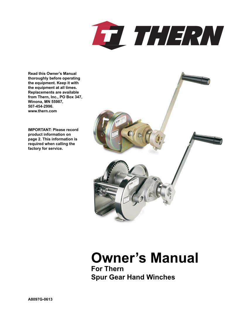
Owner’s Man ualFor Thern
Spur Gear Hand Winches
IMPORTANT: Please record
product information on
page 2. This information is
re quired when calling the
fac to ry for service.
A8097G-0613
Owner's Manual for Thern Spur Gear Hand Winchespage 2
A8097G-0613
Two-Year Limited Warranty
Thern, Inc. warrants its products against defects in material or workmanship for two years from the date of purchase
by the original using buyer, or if this date cannot be established, the date the product was sold by Thern, Inc. to the
dealer. To make a claim under this warranty, contact the factory for an RGA number. The product must be returned,
prepaid, directly to Thern, Inc., 5712 Industrial Park Road, Winona, Minnesota 55987. The following information
must accompany the product: the RGA number, the date of purchase, the description of the claimed defect, and a com-
plete explanation of the circumstances involved. If the product is found to be defective, it will be repaired or replaced
free of charge, and Thern, Inc. will reimburse the shipping cost within the contiguous USA.
This warranty does not cover any damage due to accident, misuse, abuse, or negligence. Any alteration, repair or
modifi cation of the product outside the Thern, Inc. factory shall void this warranty. This warranty does not cover any
costs for removal of our product, downtime, or any other incidental or consequential costs or damages resulting from
the claimed defects. This warranty does not cover brake discs, wire rope or other wear components, as their life is
subject to use conditions which vary between applications.
FACTORY AUTHORIZED REPAIR OR REPLACEMENT AS PROVIDED UNDER THIS WARRANTY IS THE
EXCLUSIVE REMEDY TO THE CONSUMER. THERN, INC. SHALL NOT BE LIABLE FOR ANY INCIDEN-
TAL OR CONSEQUENTIAL DAMAGES FOR BREACH OF ANY EXPRESS OR IMPLIED WARRANTY ON
THIS PRODUCT. EXCEPT TO THE EXTENT PROHIBITED BY APPLICABLE LAW, ANY IMPLIED WAR-
RANTY OF MERCHANTABILITY OR FITNESS FOR A PARTICULAR PURPOSE ON THIS PRODUCT IS
LIMITED IN DURATION TO THE DURATION OF THIS WARRANTY.
Some states do not allow the exclusion or limitation of incidental or consequential damages, or allow limitations on
how long an implied warranty lasts, so the above limitation or exclusion may not apply to you. This warranty gives
you specifi c legal rights, and you may also have other rights which vary from state to state.
Note: Thern, Inc. reserves the right to change the design or discontinue the production of any product without
prior notice.
About This Manual
The Occupational Safety and Health Act of 1970 states that it is the employer’s
re spon si bil i ty to provide a workplace free of hazard. To this end, all equipment
should be installed, operated, and maintained in compliance with applicable trade,
industrial, federal, state, and local regulations. It is the equipment own er's re spon -
si bil i ty to ob tain copies of these regulations and to determine the suit abil i ty of the
equip ment to its intended use.
This Owner’s Manual, and warning labels attached to the equip ment, are to serve
as guidelines for hazard-free installation, op er a tion, and maintenance. They should
not be understood to prepare you for every pos si ble situation.
The information contained in this manual is applicable only to the Thern Spur
Gear Hand Winches. Do not use this manual as a source of in for ma tion for any
other equip ment.
The following symbols are used for emphasis throughout this man u al:
Failure to follow ‘WARNING!’ instructions may result in equipment dam age,
property damage, and/or serious personal injury.
Failure to follow ‘CAUTION!’ instructions may result in equipment damage,
prop er ty damage, and/or minor personal injury.
Important!
Failure to follow ‘important!’ instructions may result in poor per for mance of
the equipment.
Please record the following:
Date Purchased:
Model No.:
Code No.:
This information is required when
calling the factory for service.
Owner's Manual for Thern Spur Gear Hand Winches page 3
A8097G-0613
Suggestions for Safe Operation
DO the following:
Read and comply with the guidelines set forth in this Owner’s Manual. Keep
this manual, and all labels attached to the winch, readable and with the equip-
ment at all times. Contact Thern, Inc. for replacements.
Check lubrication before use.
Install the wire rope securely to the winch drum.
Keep at least 4 wraps of wire rope wound on the drum at all times, to serve as
anchor wraps. With less than 4 wraps on the drum the wire rope could come
loose, causing the load to escape.
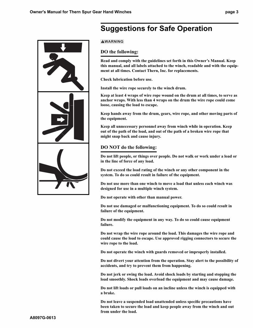
Keep hands away from the drum, gears, wire rope, and other moving parts of
the equipment.
Keep all unnecessary personnel away from winch while in operation. Keep
out of the path of the load, and out of the path of a broken wire rope that
might snap back and cause injury.
DO NOT do the following:
Do not lift people, or things over people. Do not walk or work under a load or
in the line of force of any load.
Do not exceed the load rating of the winch or any other component in the
sys tem. To do so could result in failure of the equipment.
Do not use more than one winch to move a load that unless each winch was
designed for use in a multiple winch system.
Do not operate with other than manual power.
Do not use damaged or malfunctioning equipment. To do so could result in
fail ure of the equipment.
Do not modify the equipment in any way. To do so could cause equipment
fail ure.
Do not wrap the wire rope around the load. This damages the wire rope and
could cause the load to escape. Use approved rigging connectors to secure the
wire rope to the load.
Do not operate the winch with guards removed or improperly installed.
Do not divert your attention from the operation. Stay alert to the possibility of
accidents, and try to prevent them from happening.
Do not jerk or swing the load. Avoid shock loads by starting and stopping the
load smoothly. Shock loads overload the equipment and may cause damage.
Do not lift loads or pull loads on an incline unless the winch is equipped with
a brake.
Do not leave a suspended load unattended unless specifi c precautions have
been taken to secure the load and keep people away from the winch and out
from under the load.
Owner's Manual for Thern Spur Gear Hand Winchespage 4
A8097G-0613
1.1 Installing the Winch
Do not install the winch in an area defi ned as hazardous by the National Elec-
tric Code, unless installation in such an area has been thoroughly ap proved.
Do not install the winch near corrosive chemicals, fl ammable materials, ex-
plo sives, or other elements that may damage the winch or injure the op er a tor.
Ad e quate ly protect the winch and the operator from such elements.
Position the winch so the operator can stand clear of the load, and out of the
path of a broken wire rope that could snap back and cause injury.
Attach the winch to a rigid and level foundation that will support the winch
and its load under all load conditions, including shock loading.
Install the wire rope securely to the winch drum. A poorly secured wire rope
could come loose from its anchor and could release the load. See Figure 3.
1.1.1 CONSULT APPLICABLE CODES AND REGULATIONS for specifi c rules
on installing the equipment.
1.1.2 LOCATE THE WINCH in an area clear of traffi c and obstacles that could inter-
fere with operation. Make sure winch is accessible for maintenance and operation.
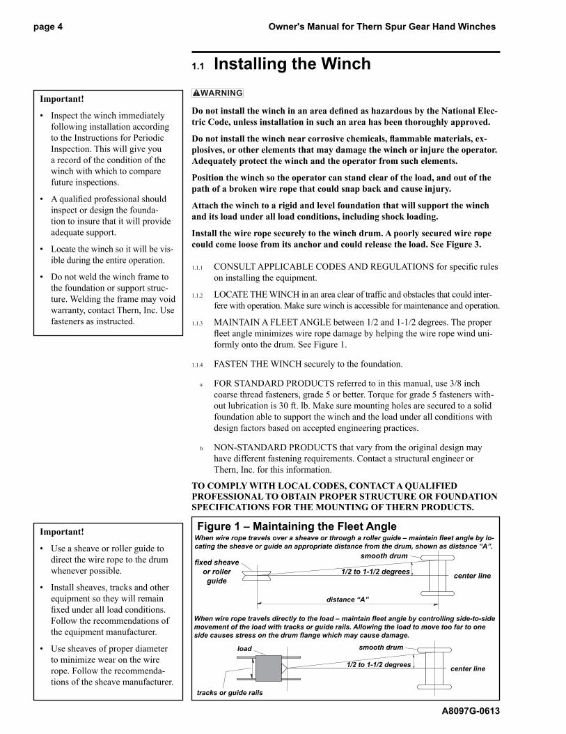
1.1.3 MAINTAIN A FLEET ANGLE between 1/2 and 1-1/2 degrees. The proper
fl eet angle minimizes wire rope damage by helping the wire rope wind uni -
form ly onto the drum. See Figure 1.
1.1.4 FASTEN THE WINCH securely to the foundation.
a FOR STANDARD PRODUCTS referred to in this manual, use 3/8 inch
coarse thread fasteners, grade 5 or better. Torque for grade 5 fasteners with-
out lubrication is 30 ft. lb. Make sure mounting holes are secured to a solid
foundation able to support the winch and the load under all conditions with
design factors based on accepted engineering practices.
b NON-STANDARD PRODUCTS that vary from the original design may
have different fastening requirements. Contact a structural engineer or
Thern, Inc. for this information.
TO COMPLY WITH LOCAL CODES, CONTACT A QUAL I FIED
PRO FES SION AL TO OBTAIN PROPER STRUCTURE OR FOUN DA TION
SPEC I FI CA TIONS FOR THE MOUNTING OF THERN PROD UCTS.
Important!
• Inspect the winch immediately
following installation according
to the Instructions for Periodic
Inspection. This will give you
a record of the condition of the
winch with which to compare
future inspections.
• A qualifi ed professional should
inspect or design the founda-
tion to insure that it will provide
adequate support.
• Locate the winch so it will be vis-
ible during the entire op er a tion.
• Do not weld the winch frame to
the foundation or support struc-
ture. Welding the frame may void
warranty, contact Thern, Inc. Use
fasteners as instructed.
Figure 1 – Maintaining the Fleet AngleWhen wire rope travels over a sheave or through a roller guide – main tain fl eet angle by lo-
cating the sheave or guide an appropriate distance from the drum, shown as distance “A”.
smooth drum
1/2 to 1-1/2 de grees
distance “A”
center line
fi xed sheave
or roller
guide
When wire rope travels directly to the load – maintain fl eet angle by con trol ling side-to-side
movement of the load with tracks or guide rails. Allowing the load to move too far to one
side causes stress on the drum fl ange which may cause damage.
1/2 to 1-1/2 de greescenter line
smooth drum
tracks or guide rails
load
Important!
• Use a sheave or roller guide to
direct the wire rope to the drum
whenever possible.
• Install sheaves, tracks and other
equipment so they will remain
fi xed under all load conditions.
Follow the recommendations of
the equipment manufacturer.
• Use sheaves of proper diameter
to minimize wear on the wire
rope. Follow the recommenda-
tions of the sheave manufacturer.
Owner's Manual for Thern Spur Gear Hand Winches page 5
A8097G-0613
1.2 Installing the Handle
1.2.1 FOR MODELS M4022PB, M4032PB, M4042PBSS, M4312PB,
M4312PBSS, and M4412PB equipped with PB Brakes, in stall the handle as
fol lows:
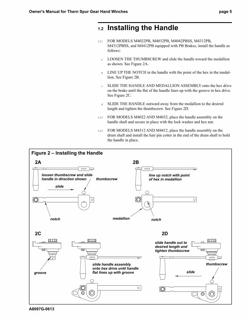
a LOOSEN THE THUMBSCREW and slide the han dle to ward the me dal lion
as shown. See Figure 2A.
b LINE UP THE NOTCH in the handle with the point of the hex in the me dal -
lion. See Figure 2B.
c SLIDE THE HANDLE AND MEDALLION ASSEMBLY onto the hex drive
on the brake until the fl at of the handle lines up with the groove in hex drive.
See Figure 2C.
d SLIDE THE HANDLE outward away from the medallion to the desired
length and tighten the thumbscrew. See Figure 2D.
1.2.2 FOR MODELS M4022 AND M4032, place the handle as sem bly on the
handle shaft and secure in place with the lock washer and hex nut.
1.2.3 FOR MODELS M4312 AND M4412, place the handle as sem bly on the
drum shaft and install the hair pin cot ter in the end of the drum shaft to hold
the handle in place.
Figure 2 – Installing the Handle
2A 2B
2C 2D
slide
thumbscrew
notch
loosen thumbscrew and slide handle in direction shown
medallion notch
line up notch with point of hex in medallion
groove
slide handle assembly onto hex drive until handle fl at lines up with groove slide
thumbscrew
slide handle out to desired length and tighten thumbscrew
Owner's Manual for Thern Spur Gear Hand Winchespage 6
A8097G-0613
1.3 Installing the Wire Rope
Install the wire rope so it is wound correctly as shown, or the winch will not
work properly, and could release the load.
Install the wire rope securely to the winch drum. A poorly secured wire rope
could come loose from its anchor and could release the load.
1.3.1 PURCHASE THE PROPER WIRE ROPE for your application. Keep the
following in mind when selecting a wire rope. Contact a repuTable wire rope
sup pli er for help.
a BREAKING STRENGTH of new wire rope should be at least 3 times
great er than the largest load placed on the winch. If loads are lifted or pulled
on an incline, the breaking strength must be at least 5 times greater than the
largest load. These are minimum values and will vary with the type of load
and how you are moving it.
b WIRE ROPE LAY must agree with the winding direction of the drum to help
insure proper winding.
c WE RECOMMEND 7 x 19 galvanized aircraft cable for diameters up to
5/16 inch.
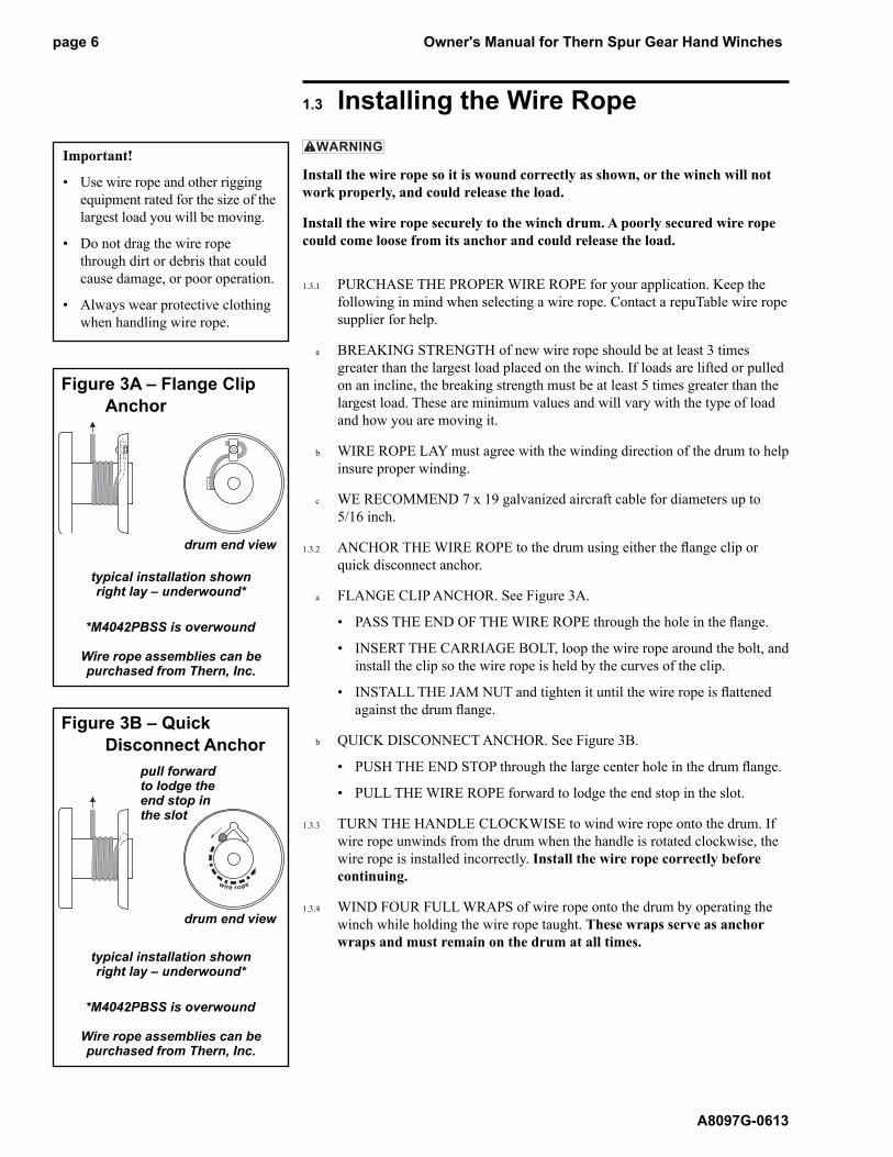
1.3.2 ANCHOR THE WIRE ROPE to the drum using either the fl ange clip or
quick disconnect anchor.
a FLANGE CLIP ANCHOR. See Figure 3A.
• PASS THE END OF THE WIRE ROPE through the hole in the fl ange.
• INSERT THE CARRIAGE BOLT, loop the wire rope around the bolt, and
install the clip so the wire rope is held by the curves of the clip.
• INSTALL THE JAM NUT and tighten it until the wire rope is fl attened
against the drum fl ange.
b QUICK DISCONNECT ANCHOR. See Figure 3B.
• PUSH THE END STOP through the large center hole in the drum fl ange.
• PULL THE WIRE ROPE forward to lodge the end stop in the slot.
1.3.3 TURN THE HANDLE CLOCKWISE to wind wire rope onto the drum. If
wire rope unwinds from the drum when the han dle is rotated clock wise, the
wire rope is installed incorrectly. Install the wire rope correctly before
con tinu ing.
1.3.4 WIND FOUR FULL WRAPS of wire rope onto the drum by operating the
winch while holding the wire rope taught. These wraps serve as anchor
wraps and must remain on the drum at all times.
Important!
• Use wire rope and other rigging
equipment rated for the size of the
largest load you will be moving.
• Do not drag the wire rope
through dirt or debris that could
cause damage, or poor operation.
• Always wear protective clothing
when handling wire rope.
Figure 3A – Flange Clip
Anchor
drum end view
typical installation shownright lay – underwound*
*M4042PBSS is overwound
Wire rope assemblies can be purchased from Thern, Inc.
Figure 3B – Quick
Disconnect Anchor
drum end view
typical installation shownright lay – underwound*
*M4042PBSS is overwound
Wire rope assemblies can be purchased from Thern, Inc.
pull forward to lodge the end stop in the slot
Owner's Manual for Thern Spur Gear Hand Winches page 7
A8097G-0613
2.1 General Theory of Operation
2.1.1 THE PULL REQUIRED to move the load must not exceed the load rating of
the winch. Consider the total force required to move the load, not the weight
of the load.
2.1.2 THIS EQUIPMENT CAN develop forces that will exceed the load rat ing.
It is the responsibility of the equipment user to limit the size of the load.
In spect the equipment regularly for damage according to the instructions
contained in this manual.
2.1.3 USE A DISC BRAKE on all hand winches used to lift loads or pull loads on
an incline.
2.1.4 PERFORMANCE RATINGS of the equipment are affected by the amount of
wire rope wound on the drum, the way in which it is wound, and the way the
winch is used.
a DRUM CAPACITY depends on how tightly and evenly the wire rope is
wound on the drum. Actual drum capacities are usually 25-30% less than
val ues shown in performance Tables, due to loose winding and overlapping.
b FORCE REQUIRED TO LIFT the load increases with each additional layer
of wire rope wound onto the drum. The value shown in per for mance Tables
is based on an empty drum and maximum handle length.
c LOAD RATING represents the maximum pull that can be placed on new
equip ment. Load ratings are assigned values for specifi c amounts of load
travel or wire rope accumulation. The load rating de creas es as layers of wire
rope accumulate on the drum.
2.1.5 DUTY RATINGS refer to the type of use the equipment is subject to. Con-
sid er the following when determining duty rating.
a ENVIRONMENT: harsh environments include hot, cold, dirty, wet, cor-
ro sive, or explosive surroundings. Protect the equipment from harsh en vi -
ron ments when possible.
b MAINTENANCE: poor maintenance, meaning poor cleaning, lu bri ca tion,
or inspection, leads to poor operation and possible damage of the equip ment.
Minimize poor maintenance by carefully following the in struc tions con-
tained in this manual.
c LOADING: severe loading includes shock loading and moving loads that
ex ceed the load rating of the equipment. Avoid shock loads, and do not
exceed the load rating of the equipment.
d FREQUENCY OF OPERATION: frequent or lengthy operations in crease
wear and shorten the life span of gears, bearings, and other components.
Increase maintenance of the equipment if used in frequent operations.
2.1.6 AIRBORNE NOISE EMISSIONS vary depending on load and the type of
winch being used. Standard confi gurations do not typically exceed a sound
pressure level of 80dB(A) at workstations.
CONTACT THE FACTORY FOR MORE INFORMATION.
Important!
• Limit nonuniform winding by
keeping tension on the wire rope
and by maintaining the proper
fl eet angle.
• It is your responsibility to detect
and account for different fac-
tors affecting the condition and
per for mance of the equipment.
Owner's Manual for Thern Spur Gear Hand Winchespage 8
A8097G-0613
Important!
• When determining whether the
load will exceed the load rating,
consider the total force required
to move the load.
2.2 Breaking-In the Winch
2.2.1 BREAK-IN OCCURS during the fi rst 10 hours of normal operation. During
break-in, mating surfaces become polished, and clearances increase. This is
desired for effi cient operation of bearings and gears.
2.2.2 INSPECT THE WINCH following break-in according to the Instructions for
Periodic Inspection.
2.3 Preparing for Operation
2.3.1 CONSIDER THE OPERATION. Do not begin until you are sure you can
perform the entire operation without hazard.
2.3.2 INSPECT ALL COMPONENTS of the system.
a INSPECT THE WINCH and other equipment according to the Instructions
for Frequent Inspection.
b OPERATORS must be in good health, alert, thoroughly trained in operat-
ing the equipment, and properly clothed (hard hat, safety shoes and safety
glass es, no loose clothing).
c THE LOAD must be clear of other objects and free to move. Make sure the
load will not tip, spin, roll away, or in any way move uncontrollably.
2.3.3 KNOW YOUR LOAD and make sure you do not exceed the load rating of
the winch or any other equipment in the system.
Owner's Manual for Thern Spur Gear Hand Winches page 9
A8097G-0613
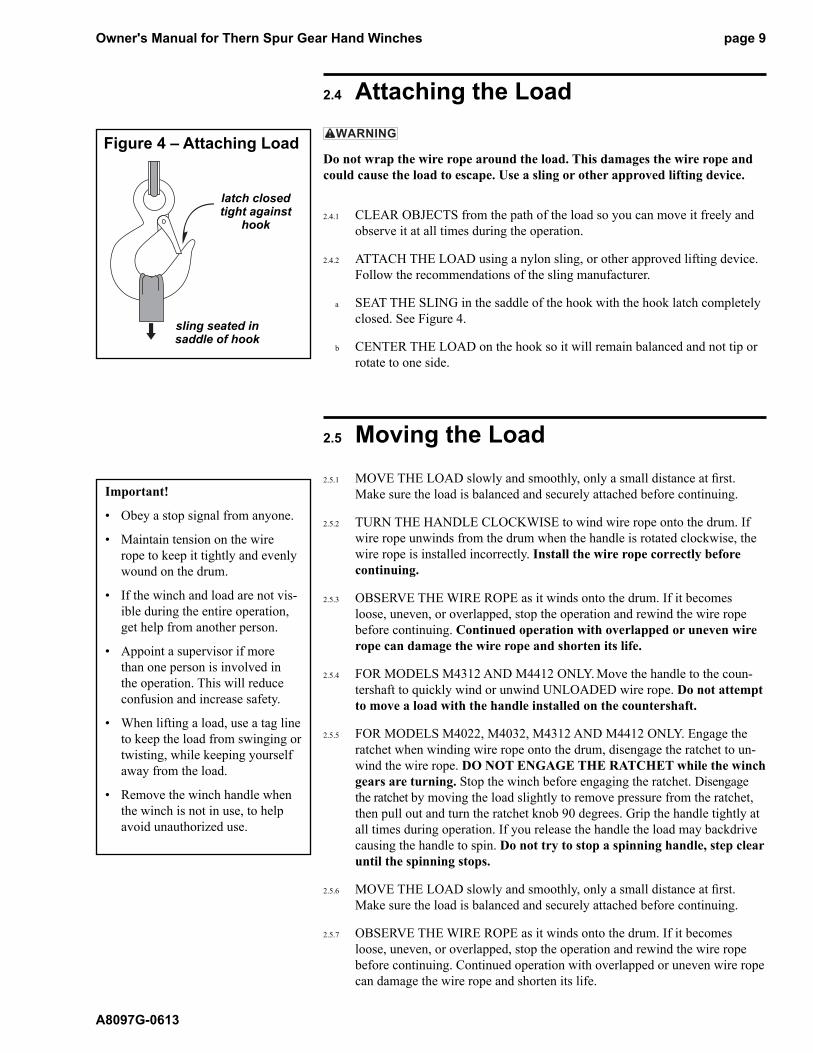
2.4 Attaching the Load
Do not wrap the wire rope around the load. This damages the wire rope and
could cause the load to escape. Use a sling or other approved lifting device.
2.4.1 CLEAR OBJECTS from the path of the load so you can move it freely and
observe it at all times during the operation.
2.4.2 ATTACH THE LOAD using a nylon sling, or other approved lifting de vice.
Follow the recommendations of the sling manufacturer.
a SEAT THE SLING in the saddle of the hook with the hook latch com plete ly
closed. See Figure 4.
b CENTER THE LOAD on the hook so it will remain balanced and not tip or
rotate to one side.
2.5 Moving the Load
2.5.1 MOVE THE LOAD slowly and smoothly, only a small distance at fi rst.
Make sure the load is balanced and securely attached before con tinu ing.
2.5.2 TURN THE HANDLE CLOCKWISE to wind wire rope onto the drum. If
wire rope unwinds from the drum when the handle is rotated clockwise, the
wire rope is installed incorrectly. Install the wire rope cor rect ly before
con tinu ing.
2.5.3 OBSERVE THE WIRE ROPE as it winds onto the drum. If it becomes
loose, uneven, or overlapped, stop the operation and rewind the wire rope
before continuing. Continued operation with overlapped or uneven wire
rope can damage the wire rope and shorten its life.
2.5.4 FOR MODELS M4312 AND M4412 ONLY. Move the handle to the coun-
tershaft to quickly wind or unwind UNLOADED wire rope. Do not attempt
to move a load with the handle installed on the countershaft.
2.5.5 FOR MODELS M4022, M4032, M4312 AND M4412 ONLY. Engage the
ratchet when winding wire rope onto the drum, dis en gage the ratchet to un-
wind the wire rope. DO NOT ENGAGE THE RATCHET while the winch
gears are turn ing. Stop the winch before engaging the ratch et. Disengage
the ratchet by moving the load slightly to re move pres sure from the ratchet,
then pull out and turn the ratchet knob 90 de grees. Grip the handle tightly at
all times during operation. If you re lease the handle the load may backdrive
causing the handle to spin. Do not try to stop a spinning handle, step clear
until the spinning stops.
2.5.6 MOVE THE LOAD slowly and smoothly, only a small distance at fi rst.
Make sure the load is balanced and securely attached before continuing.
2.5.7 OBSERVE THE WIRE ROPE as it winds onto the drum. If it becomes
loose, uneven, or overlapped, stop the operation and rewind the wire rope
before continuing. Continued operation with overlapped or uneven wire rope
can damage the wire rope and shorten its life.
Important!
• Obey a stop signal from anyone.
• Maintain tension on the wire
rope to keep it tightly and evenly
wound on the drum.
• If the winch and load are not vis-
ible during the entire op er a tion,
get help from another person.
• Appoint a supervisor if more
than one person is involved in
the operation. This will reduce
con fu sion and increase safety.
• When lifting a load, use a tag line
to keep the load from swinging or
twisting, while keeping yourself
away from the load.
• Remove the winch handle when
the winch is not in use, to help
avoid un au tho rized use.
Figure 4 – Attaching Load
latch closed tight against
hook
sling seated in saddle of hook
Owner's Manual for Thern Spur Gear Hand Winchespage 10
A8097G-0613
3.1 Cleaning the Winch
Clean the winch to remove dirt and help prevent rust and corrosion.
3.1.1 CLEAN THE WINCH every six months or whenever it is dirty.
a WIPE ALL EQUIPMENT to remove dirt and grease.
b LEAVE A LIGHT FILM of oil on all surfaces to protect them against rust
and corrosion.
c WIPE OFF excessive amounts of oil to avoid the accumulation of dirt.
3.1.2 REMOVE ALL UNNECESSARY OBJECTS from the area surrounding the
winch.
3.2 Lubricating the Winch
Do not over lubricate the brake bushings on models equipped with a brake.
Over lu bri cat ing may cause oil to leak onto the friction discs, which may dam-
age the fric tion discs or result in poor operation of the disc brake.
Lubricate the spur gears before each operation, and periodically during op-
er a tion. Failure to lubricate the gears will cause damage or deformation of
gear teeth.
Lubricate the winch properly to help protect it from wear and rust. Read the
following instructions carefully.
3.2.1 CONSULT MANUFACTURER’S RECOMMENDATIONS for specifi c
information on lubricating the wire rope and other equipment.
3.2.2 LUBRICATE WINCH BEARINGS AND SHAFTS at least every 6 months.
a APPLY 2 TO 3 DROPS of SAE 30 non-detergent oil to bearings and shafts
at all fric tion points.
b ROTATE THE DRUM several times to allow the oil to penetrate, and wipe
off excess oil to avoid accumulation of dirt.
3.2.3 LUBRICATE WINCH GEARS before every operation and at least every 10
hours during operation.
a APPLY A LIGHT FILM of open gear lubricant to the gear teeth on all gears.
b USE SPRAYON S00201 or equivalent open gear lube. For dirty conditions
use a dry lubricant such as dry graphite or Moly.
3.2.4 LUBRICATE THE DISC BRAKE IF APPLICABLE at least every 6
months. Place 1 or 2 drops of SAE 30 non-detergent oil into the hole in the
brake housing marked “oil”, and turn the brake several times to allow the oil
to penetrate.
3.2.5 LUBRICATE THE WIRE ROPE and other equipment by following the
man u fac tur er’s recommendations.
Important!
Increase the frequency of main te -
nance procedures if the winch is:
• Operated for long periods.
• Used to pull heavy loads.
• Operated in wet, dirty, hot, or
cold surroundings.
Important!
• Make sure lubricant has a tem-
per a ture rating appropriate for
the ambient temperatures of the
operation.
Owner's Manual for Thern Spur Gear Hand Winches page 11
A8097G-0613
3.3 Inspecting the Equipment
Do not use damaged or malfunctioning equipment. Place an “OUT OF OR DER”
sign on the winch. Do not use the winch until the sign is removed by a qual-
i fi ed maintenance person who has completely corrected the prob lem.
Inspect the winch to detect signs of damage or poor operation before they
be come hazardous.
3.3.1 CONSULT APPLICABLE CODES AND REGULATIONS for specifi c rules
on inspecting the winch and other equipment.
3.3.2 CONSULT MANUFACTURER’S RECOMMENDATIONS for in for ma tion
on inspecting the wire rope and other equipment.
Important!
• Start an inspection program as soon
as you put the winch into use.
• Appoint a qualifi ed person to be
responsible for regularly in-
spect ing the equipment.
• Keep written records of in spec -
tion. This allows comparison with
comments from previous in spec -
tions so you can see changes in
condition or per for mance.
3.3.3 Instructions for Frequent Inspection
a VISUALLY INSPECT the entire winch and all other equipment involved in
the operation.
• Check all equipment for cracks, dents, bending, rust, wear, cor ro sion and
other damage.
• Make sure the wire rope is installed correctly and anchored securely to
the drum.
• Make sure the winch and brake are properly lubricated.
• Make sure fasteners are installed to securely hold the handle in place.
• Make sure mounting fasteners are tightened securely.
• Make sure the foundation is in good condition, and capable of sup port ing
the winch and its load under all load conditions.
b TEST WINCH PERFORMANCE by operating the winch with a load not
exceeding the load rating.
• Listen for unusual noises, and look for signs of damage as you op er ate the
winch.
• Make sure the wire rope winds evenly and tightly onto the drum. If it is
loose or uneven, rewind it before continuing.
• Make sure the handle rotates freely in both directions.
• Make sure the load moves smoothly without hesitation or strain.
• On models equipped with a ratchet, make sure the ratchet engages and
disengages completely.
• On models equipped with a brake, make sure the disc brake ratchet pawl
clicks fi rm ly as the brake han dle is turned clockwise.
• On models equipped with a brake, check the brake. Raise the load, then
lower it and stop it a few feet off the ground. If the load continues to coast
or creep under normal operating conditions, the friction discs may be worn
and in need of re place ment. Contact the factory.
Completely correct all problems before continuing. Use the Trou ble shoot ing
Chart to help determine the cause of certain problems. See Table 2.
Perform frequent inspections:
• Before each operation.
• Every 3 hours during operation.
• Whenever you notice signs of
damage or poor operation.
Frequent Wire Rope Inspection:
• Use ASME B30.7 as a guideline
for rope inspection, replacement
and maintenance.
• Check the wire rope, end connec-
tions and end fi ttings for corrosion
kinking, bending, crushing, bird-
caging or other signs of damage.
• Check the number, distribution and
type of visible broken wires. See
paragraph 3.3.4 b and Figure 5.
• Check the wire rope for reduc-
tion of rope diameter from loss of
core support, or wear of outside
wires. See Figure 7.
• Take extra care when inspecting
sections of rapid deterioration
such as sections in contact with
saddles, sheaves, repetitive pickup
points, crossover points and end
connections.
Owner's Manual for Thern Spur Gear Hand Winchespage 12
A8097G-0613
3.3.4 Instructions for Periodic Inspection, see Table 1.
a VISUALLY INSPECT the winch and all other equipment.
• Disassembly may be required in order to properly inspect individual com-
ponents. Contact factory for assembly/disassembly instructions. Disassem-
bly of the winch or brake before contacting Thern, Inc. voids all warranties.
• Check the fi nish for wear, fl aking, or other damage.
• Check all equipment, including wire rope for cracks, dents, bending, rust,
wear, cor ro sion and other damage. If the winch was overloaded, or if
you notice cracks and other signs of overloading and damage promptly
remove equipment from use and have it repaired or replaced. DO NOT
CONTINUE TO USE DAMAGED OR OVERLOADED EQUIP-
MENT OR WIRE ROPE.
• Check all fasteners for stripped threads, wear, bending, and other dam age.
• Check the foundation for cracks, corrosion, and other damage.
• Make sure the winch and brake are properly lubricated.
• Make sure all labels and plates are readable, fi rmly attached, free of dam-
age and clean. Replacements are available from the factory.
b REMOVE THE WIRE ROPE entirely from the drum.
• Always wear protective clothing when handling wire rope.
• Check the entire length of wire rope for bent wires, crushed areas, bro ken
or cut wires, corrosion, and other damage. Care ful ly inspect areas that
pass over sheaves or through roller guides.
• Note the location and concentration of broken wires. Replace wire rope if
more than 6 wires are broken in one lay, or more than 3 wires are broken
in one strand in one lay. See Figure 5.
• Make sure the load hook or other device is securely attached to the wire
rope, and the wire rope where it is attached is not frayed, cor rod ed, bro-
ken, or otherwise damaged.
• Measure the throat opening, thickness, and twist of the hook. Re place the
hook if it shows signs of damage. See Figure 6.
• Make sure hook latch opens without binding and closes when re leased.
• Check the anchor holes in the drum fl ange for signs of wear or dis tor tion.
c PLACE enough weight to keep the wire rope straight and tightly drawn.
• Measure the diameter of the wire rope, especially in areas where wear
is noticeable. Replace the wire rope if the diameter measures below the
min i mum diameter at any point. See Figure 7.
d REMOVE THE WINCH from the foundation.
• Check fasteners for stripped threads, wear, bends, and other damage.
• Check the frame for bending, distortion, cracks and other dam age. A bent
frame is caused by over load ing, and is a sign that your application may
require a winch with a larger load rating.
e MOVE THE DRUM with your hands.
• Check for excessive movement indicating worn or loose gears, bear ings,
or shafts.
Perform periodic inspections:
• Every 6 months.
• Whenever you return the winch
to service from storage.
• Whenever you notice damage
or poor operation in a frequent
in spec tion.
• Whenever you have, or think you
may have, overloaded or shock
loaded the winch.
wire
strand
onelay
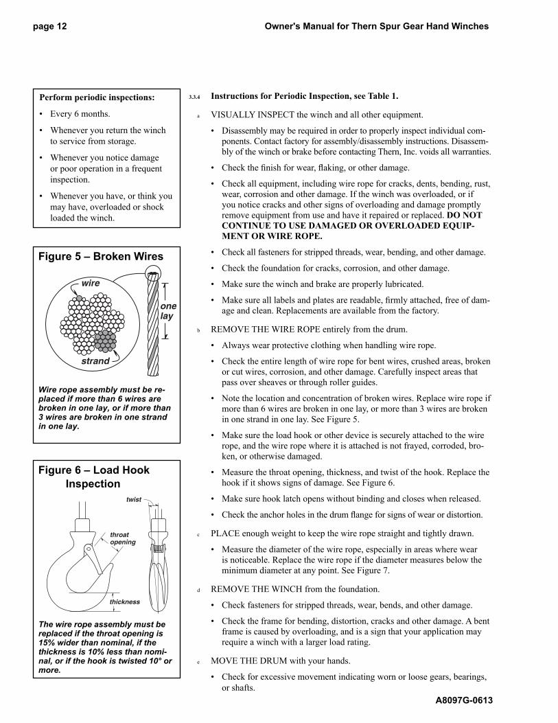
Figure 5 – Broken Wires
Wire rope assembly must be re- placed if more than 6 wires are bro ken in one lay, or if more than 3 wires are broken in one strand in one lay.
twist
throat opening
thickness
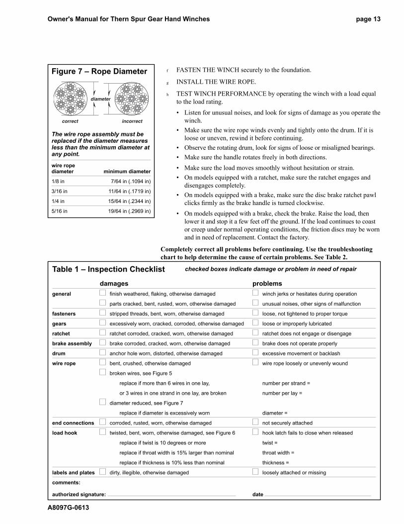
Figure 6 – Load Hook
Inspection
The wire rope assembly must be replaced if the throat opening is 15% wider than nominal, if the thick ness is 10% less than nomi-nal, or if the hook is twisted 10° or more.
Owner's Manual for Thern Spur Gear Hand Winches page 13
A8097G-0613
f FASTEN THE WINCH securely to the foundation.
g INSTALL THE WIRE ROPE.
h TEST WINCH PERFORMANCE by operating the winch with a load equal
to the load rating.
• Listen for unusual noises, and look for signs of damage as you op er ate the
winch.
• Make sure the wire rope winds evenly and tightly onto the drum. If it is
loose or uneven, rewind it before continuing.
• Observe the rotating drum, look for signs of loose or misaligned bear ings.
• Make sure the handle rotates freely in both directions.
• Make sure the load moves smoothly without hesitation or strain.
• On models equipped with a ratchet, make sure the ratchet engages and
disengages completely.
• On models equipped with a brake, make sure the disc brake ratchet pawl
clicks fi rm ly as the brake han dle is turned clockwise.
• On models equipped with a brake, check the brake. Raise the load, then
lower it and stop it a few feet off the ground. If the load continues to coast
or creep under normal operating conditions, the friction discs may be worn
and in need of re place ment. Contact the factory.
Completely correct all problems before continuing. Use the trou ble shoot ing
chart to help determine the cause of certain problems. See Table 2.
diameter
correct incorrect
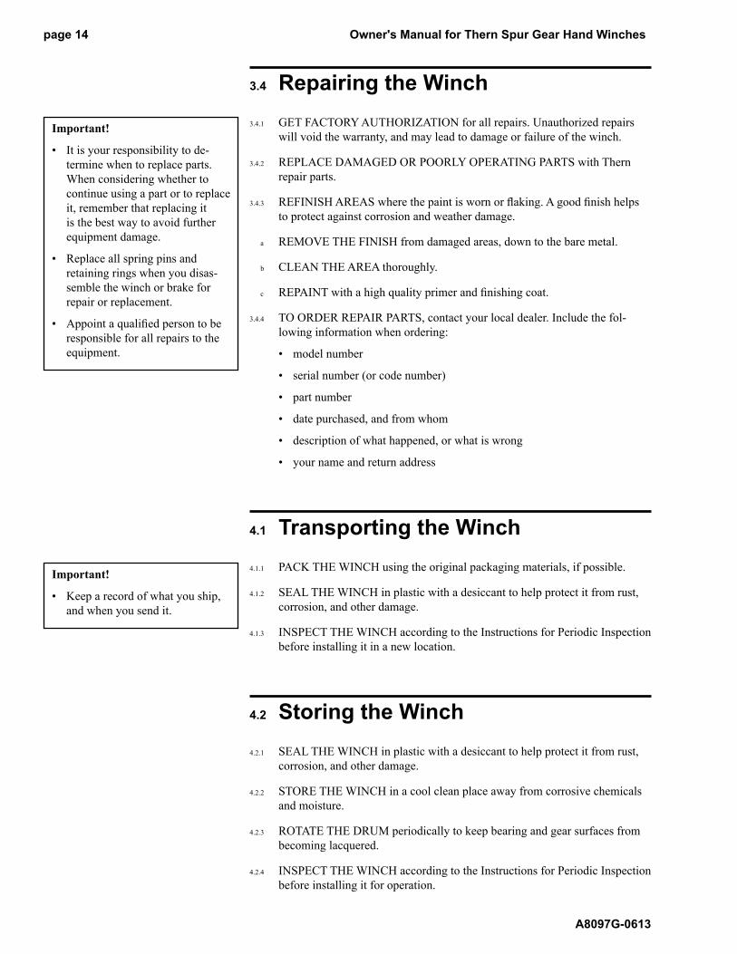
Figure 7 – Rope Diameter
The wire rope assembly must be replaced if the diameter measures less than the minimum diameter at any point.
wire ropediameter minimum diameter
1/8 in 7/64 in (.1094 in)
3/16 in 11/64 in (.1719 in)
1/4 in 15/64 in (.2344 in)
5/16 in 19/64 in (.2969 in)
Table 1 – Inspection Checklist
damages problems
general fi nish weathered, fl aking, otherwise damaged winch jerks or hesitates during operation
parts cracked, bent, rusted, worn, otherwise damaged unusual noises, other signs of malfunction
fasteners stripped threads, bent, worn, otherwise damaged loose, not tightened to proper torque
gears excessively worn, cracked, corroded, otherwise damaged loose or improperly lubricated
ratchet ratchet corroded, cracked, worn, otherwise damaged ratchet does not engage or disengage
brake assembly brake corroded, cracked, worn, otherwise damaged brake does not operate properly
drum anchor hole worn, distorted, otherwise damaged excessive movement or backlash
wire rope bent, crushed, otherwise damaged wire rope loosely or unevenly wound
broken wires, see Figure 5
replace if more than 6 wires in one lay, number per strand =
or 3 wires in one strand in one lay, are broken number per lay =
diameter reduced, see Figure 7
replace if diameter is excessively worn diameter =
end connections corroded, rusted, worn, otherwise damaged not securely attached
load hook twisted, bent, worn, otherwise damaged, see Figure 6 hook latch fails to close when released
replace if twist is 10 degrees or more twist =
replace if throat width is 15% larger than nominal throat width =
replace if thickness is 10% less than nominal thickness =
labels and plates dirty, illegible, otherwise damaged loosely attached or missing
comments:
authorized signature: date
checked boxes indicate damage or problem in need of repair
Owner's Manual for Thern Spur Gear Hand Winchespage 14
A8097G-0613
3.4 Repairing the Winch
3.4.1 GET FACTORY AUTHORIZATION for all repairs. Unauthorized repairs
will void the warranty, and may lead to damage or failure of the winch.
3.4.2 REPLACE DAMAGED OR POORLY OPERATING PARTS with Thern
repair parts.
3.4.3 REFINISH AREAS where the paint is worn or fl aking. A good fi nish helps
to protect against corrosion and weather damage.
a REMOVE THE FINISH from damaged areas, down to the bare metal.
b CLEAN THE AREA thoroughly.
c REPAINT with a high quality primer and fi nishing coat.
3.4.4 TO ORDER REPAIR PARTS, contact your local dealer. Include the fol-
low ing in for ma tion when ordering:
• model number
• serial number (or code number)
• part number
• date purchased, and from whom
• description of what happened, or what is wrong
• your name and return address
4.1 Transporting the Winch
4.1.1 PACK THE WINCH using the original packaging materials, if possible.
4.1.2 SEAL THE WINCH in plastic with a desiccant to help protect it from rust,
corrosion, and other damage.
4.1.3 INSPECT THE WINCH according to the Instructions for Periodic In spec tion
before installing it in a new location.
4.2 Storing the Winch
4.2.1 SEAL THE WINCH in plastic with a desiccant to help protect it from rust,
cor ro sion, and other damage.
4.2.2 STORE THE WINCH in a cool clean place away from corrosive chem i cals
and moisture.
4.2.3 ROTATE THE DRUM periodically to keep bearing and gear surfaces from
becoming lacquered.
4.2.4 INSPECT THE WINCH according to the Instructions for Periodic In spec tion
before installing it for operation.
Important!
• It is your responsibility to de-
ter mine when to replace parts.
When considering whether to
continue using a part or to replace
it, re mem ber that replacing it
is the best way to avoid further
equipment damage.
• Replace all spring pins and
retaining rings when you dis as -
sem ble the winch or brake for
repair or replacement.
• Appoint a qualifi ed person to be
responsible for all repairs to the
equipment.
Important!
• Keep a record of what you ship,
and when you send it.
Owner's Manual for Thern Spur Gear Hand Winches page 15
A8097G-0613
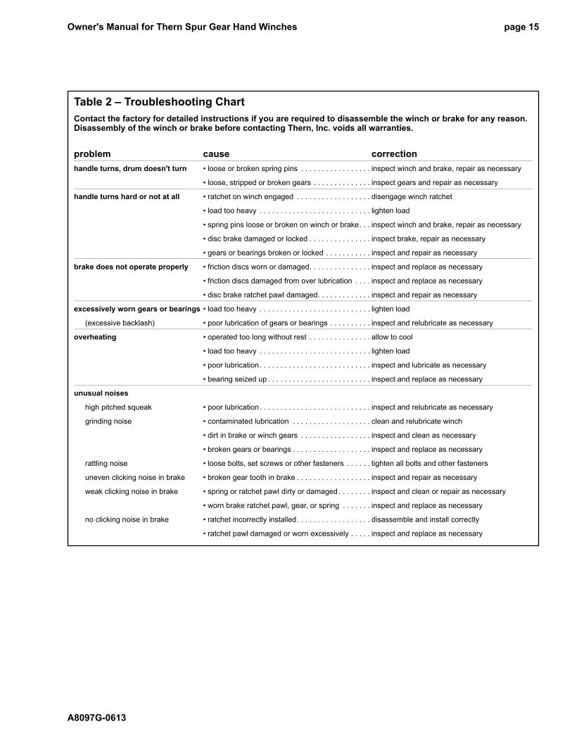
Table 2 – Troubleshooting Chart
Contact the factory for detailed instructions if you are required to disassemble the winch or brake for any reason. Disassembly of the winch or brake before contacting Thern, Inc. voids all warranties.
problem cause correction
handle turns, drum doesn't turn • loose or broken spring pins . . . . . . . . . . . . . . . . . inspect winch and brake, repair as necessary
• loose, stripped or broken gears . . . . . . . . . . . . . . inspect gears and repair as necessary
handle turns hard or not at all • ratchet on winch engaged . . . . . . . . . . . . . . . . . . disengage winch ratchet
• load too heavy . . . . . . . . . . . . . . . . . . . . . . . . . . . lighten load
• spring pins loose or broken on winch or brake . . . inspect winch and brake, repair as necessary
• disc brake damaged or locked . . . . . . . . . . . . . . . inspect brake, repair as necessary
• gears or bearings broken or locked . . . . . . . . . . . inspect and repair as necessary
brake does not operate properly • friction discs worn or damaged . . . . . . . . . . . . . . . inspect and replace as necessary
• friction discs damaged from over lubrication . . . . inspect and replace as necessary
• disc brake ratchet pawl damaged . . . . . . . . . . . . . inspect and repair as necessary
excessively worn gears or bearings • load too heavy . . . . . . . . . . . . . . . . . . . . . . . . . . . lighten load
(excessive backlash) • poor lubrication of gears or bearings . . . . . . . . . . inspect and relubricate as necessary
overheating • operated too long without rest . . . . . . . . . . . . . . . allow to cool
• load too heavy . . . . . . . . . . . . . . . . . . . . . . . . . . . lighten load
• poor lubrication . . . . . . . . . . . . . . . . . . . . . . . . . . . inspect and lubricate as necessary
• bearing seized up . . . . . . . . . . . . . . . . . . . . . . . . . inspect and replace as necessary
unusual noises
high pitched squeak • poor lubrication . . . . . . . . . . . . . . . . . . . . . . . . . . . inspect and relubricate as necessary
grinding noise • contaminated lubrication . . . . . . . . . . . . . . . . . . . clean and relubricate winch
• dirt in brake or winch gears . . . . . . . . . . . . . . . . . inspect and clean as necessary
• broken gears or bearings . . . . . . . . . . . . . . . . . . . inspect and replace as necessary
rattling noise • loose bolts, set screws or other fasteners . . . . . . tighten all bolts and other fasteners
uneven clicking noise in brake • broken gear tooth in brake . . . . . . . . . . . . . . . . . . inspect and repair as necessary
weak clicking noise in brake • spring or ratchet pawl dirty or damaged . . . . . . . . inspect and clean or repair as necessary
• worn brake ratchet pawl, gear, or spring . . . . . . . inspect and replace as necessary
no clicking noise in brake • ratchet incorrectly installed . . . . . . . . . . . . . . . . . . disassemble and install correctly
• ratchet pawl damaged or worn excessively . . . . . inspect and replace as necessary
Owner's Manual for Thern Spur Gear Hand Winchespage 16
A8097G-0613
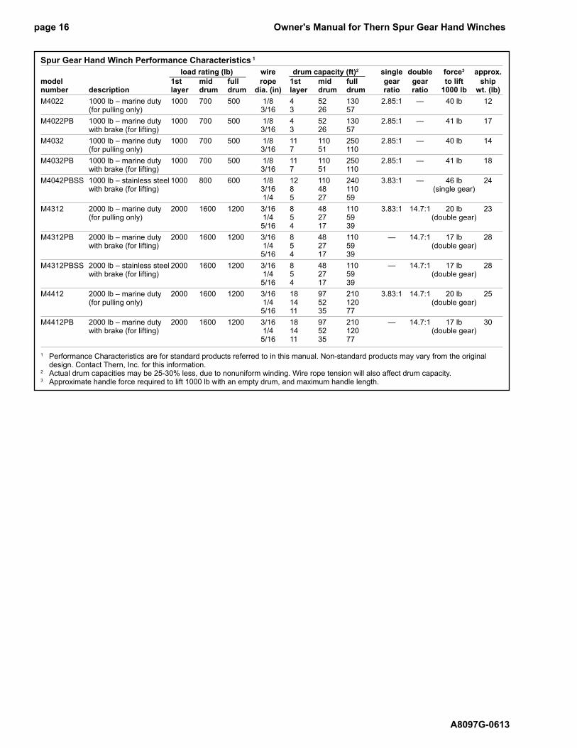
Spur Gear Hand Winch Performance Characteristics 1
load rating (lb) wire drum capacity (ft)2 single double force3 approx.
model 1st mid full rope 1st mid full gear gear to lift shipnumber description layer drum drum dia. (in) layer drum drum ratio ratio 1000 lb wt. (lb)
M4022 1000 lb – marine duty 1000 700 500 1/8 4 52 130 2.85:1 — 40 lb 12 (for pulling only) 3/16 3 26 57
M4022PB 1000 lb – marine duty 1000 700 500 1/8 4 52 130 2.85:1 — 41 lb 17 with brake (for lifting) 3/16 3 26 57
M4032 1000 lb – marine duty 1000 700 500 1/8 11 110 250 2.85:1 — 40 lb 14 (for pulling only) 3/16 7 51 110
M4032PB 1000 lb – marine duty 1000 700 500 1/8 11 110 250 2.85:1 — 41 lb 18 with brake (for lifting) 3/16 7 51 110
M4042PBSS 1000 lb – stainless steel 1000 800 600 1/8 12 110 240 3.83:1 — 46 lb 24 with brake (for lifting) 3/16 8 48 110 (single gear) 1/4 5 27 59
M4312 2000 lb – marine duty 2000 1600 1200 3/16 8 48 110 3.83:1 14.7:1 20 lb 23 (for pulling only) 1/4 5 27 59 (double gear) 5/16 4 17 39
M4312PB 2000 lb – marine duty 2000 1600 1200 3/16 8 48 110 — 14.7:1 17 lb 28 with brake (for lifting) 1/4 5 27 59 (double gear) 5/16 4 17 39
M4312PBSS 2000 lb – stainless steel 2000 1600 1200 3/16 8 48 110 — 14.7:1 17 lb 28 with brake (for lifting) 1/4 5 27 59 (double gear) 5/16 4 17 39
M4412 2000 lb – marine duty 2000 1600 1200 3/16 18 97 210 3.83:1 14.7:1 20 lb 25 (for pulling only) 1/4 14 52 120 (double gear) 5/16 11 35 77
M4412PB 2000 lb – marine duty 2000 1600 1200 3/16 18 97 210 — 14.7:1 17 lb 30 with brake (for lifting) 1/4 14 52 120 (double gear) 5/16 11 35 77
1 Performance Characteristics are for standard products referred to in this manual. Non-standard products may vary from the original design. Contact Thern, Inc. for this information. 2 Actual drum capacities may be 25-30% less, due to nonuniform winding. Wire rope tension will also affect drum capacity.3 Approximate handle force required to lift 1000 lb with an empty drum, and maximum handle length.
Owner's Manual for Thern Spur Gear Hand Winches page 17
A8097G-0613
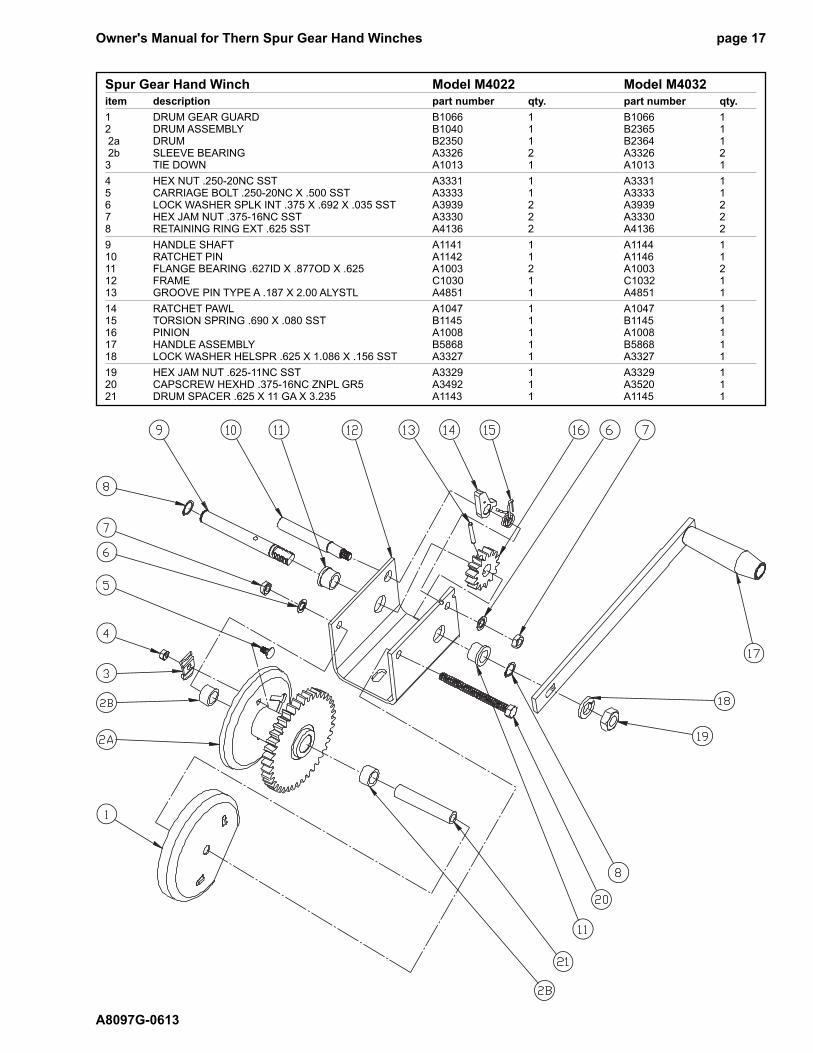
Spur Gear Hand Winch Model M4022 Model M4032
item description part number qty. part number qty.
1 DRUM GEAR GUARD B1066 1 B1066 12 DRUM ASSEMBLY B1040 1 B2365 1 2a DRUM B2350 1 B2364 1 2b SLEEVE BEARING A3326 2 A3326 23 TIE DOWN A1013 1 A1013 1
4 HEX NUT .250-20NC SST A3331 1 A3331 15 CARRIAGE BOLT .250-20NC X .500 SST A3333 1 A3333 16 LOCK WASHER SPLK INT .375 X .692 X .035 SST A3939 2 A3939 27 HEX JAM NUT .375-16NC SST A3330 2 A3330 28 RETAINING RING EXT .625 SST A4136 2 A4136 2
9 HANDLE SHAFT A1141 1 A1144 110 RATCHET PIN A1142 1 A1146 111 FLANGE BEARING .627ID X .877OD X .625 A1003 2 A1003 212 FRAME C1030 1 C1032 113 GROOVE PIN TYPE A .187 X 2.00 ALYSTL A4851 1 A4851 1
14 RATCHET PAWL A1047 1 A1047 115 TORSION SPRING .690 X .080 SST B1145 1 B1145 116 PINION A1008 1 A1008 117 HANDLE ASSEMBLY B5868 1 B5868 118 LOCK WASHER HELSPR .625 X 1.086 X .156 SST A3327 1 A3327 1
19 HEX JAM NUT .625-11NC SST A3329 1 A3329 120 CAPSCREW HEXHD .375-16NC ZNPL GR5 A3492 1 A3520 121 DRUM SPACER .625 X 11 GA X 3.235 A1143 1 A1145 1
Owner's Manual for Thern Spur Gear Hand Winchespage 18
A8097G-0613
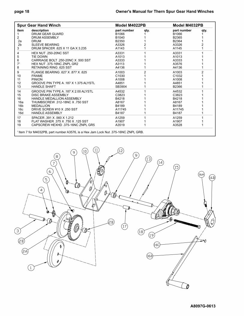
Spur Gear Hand Winch Model M4022PB Model M4032PB
item description part number qty. part number qty.1 DRUM GEAR GUARD B1066 1 B1066 12 DRUM ASSEMBLY B1040 1 B2365 1 2a DRUM B2350 1 B2364 1 2b SLEEVE BEARING A3326 2 A3326 23 DRUM SPACER .625 X 11 GA X 3.235 A1143 1 A1145 1
4 HEX NUT .250-20NC SST A3331 1 A3331 15 TIE DOWN A1013 1 A1013 16 CARRIAGE BOLT .250-20NC X .500 SST A3333 1 A3333 171 HEX NUT .375-16NC ZNPL GR2 A3113 1 A3576 18 RETAINING RING .625 SST A4136 1 A4136 1
9 FLANGE BEARING .627 X .877 X .625 A1003 2 A1003 210 FRAME C1030 1 C1032 111 PINION A1008 1 A1008 112 GROOVE PIN TYPE A .187 X 1.375 ALYSTL A4851 1 A4851 113 HANDLE SHAFT SB3904 1 B2366 1
14 GROOVE PIN TYPE A .187 X 2.00 ALYSTL A4532 1 A4532 115 DISC BRAKE ASSEMBLY C3823 1 C3823 116 HANDLE MEDALLION ASSEMBLY B4218 1 B4218 1 16a THUMBSCREW .312-18NC X .750 SST A8167 1 A8167 1 16b MEDALLION B4189 1 B4189 1 16c DRIVE SCREW #10 X .250 SST A11745 1 A11745 1 16d HANDLE ASSEMBLY B4187 1 B4187 1
17 SPACER .391 X .560 X 1.212 A1259 1 A1259 118 FLAT WASHER .375 X .750 X .125 SST A1907 1 A1907 119 CAPSCREW HEXHD .375-16NC ZNPL GR5 A3519 1 A3528 1
1 Item 7 for M4032PB, part number A3576, is a Hex Jam Lock Nut .375-16NC ZNPL GRB.
Owner's Manual for Thern Spur Gear Hand Winches page 19
A8097G-0613
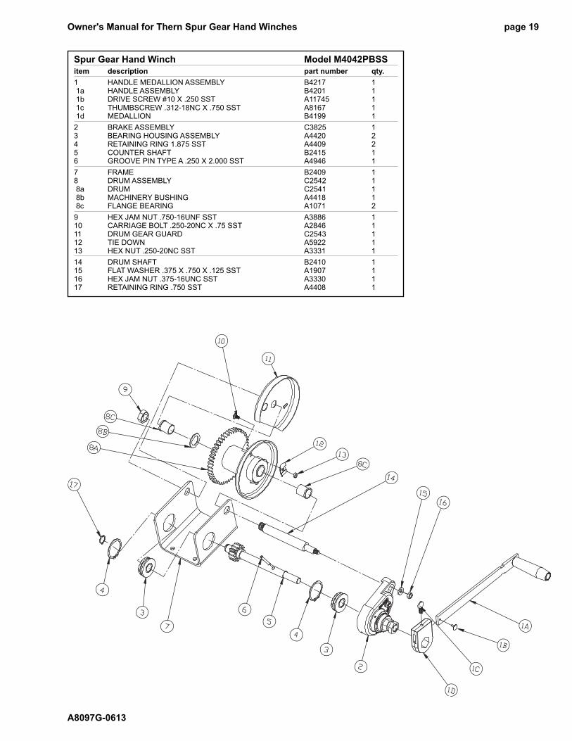
Spur Gear Hand Winch Model M4042PBSS
item description part number qty.
1 HANDLE MEDALLION ASSEMBLY B4217 1 1a HANDLE ASSEMBLY B4201 1 1b DRIVE SCREW #10 X .250 SST A11745 1 1c THUMBSCREW .312-18NC X .750 SST A8167 1 1d MEDALLION B4199 1
2 BRAKE ASSEMBLY C3825 13 BEARING HOUSING ASSEMBLY A4420 24 RETAINING RING 1.875 SST A4409 25 COUNTER SHAFT B2415 16 GROOVE PIN TYPE A .250 X 2.000 SST A4946 1
7 FRAME B2409 18 DRUM ASSEMBLY C2542 1 8a DRUM C2541 1 8b MACHINERY BUSHING A4418 1 8c FLANGE BEARING A1071 2
9 HEX JAM NUT .750-16UNF SST A3886 110 CARRIAGE BOLT .250-20NC X .75 SST A2846 111 DRUM GEAR GUARD C2543 112 TIE DOWN A5922 113 HEX NUT .250-20NC SST A3331 1
14 DRUM SHAFT B2410 115 FLAT WASHER .375 X .750 X .125 SST A1907 116 HEX JAM NUT .375-16UNC SST A3330 117 RETAINING RING .750 SST A4408 1
Owner's Manual for Thern Spur Gear Hand Winchespage 20
A8097G-0613
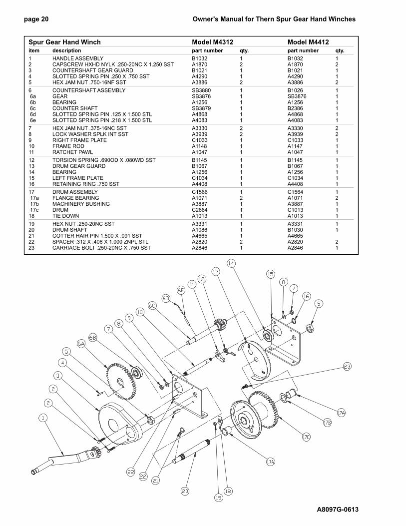
Spur Gear Hand Winch Model M4312 Model M4412
item description part number qty. part number qty.
1 HANDLE ASSEMBLY B1032 1 B1032 12 CAPSCREW HXHD NYLK .250-20NC X 1.250 SST A1870 2 A1870 23 COUNTERSHAFT GEAR GUARD B1021 1 B1021 14 SLOTTED SPRING PIN .250 X .750 SST A4290 1 A4290 15 HEX JAM NUT .750-16NF SST A3886 2 A3886 2
6 COUNTERSHAFT ASSEMBLY SB3880 1 B1026 1 6a GEAR SB3876 1 SB3876 1 6b BEARING A1256 1 A1256 1 6c COUNTER SHAFT SB3879 1 B2386 1 6d SLOTTED SPRING PIN .125 X 1.500 STL A4868 1 A4868 1 6e SLOTTED SPRING PIN .218 X 1.500 STL A4083 1 A4083 1
7 HEX JAM NUT .375-16NC SST A3330 2 A3330 28 LOCK WASHER SPLK INT SST A3939 2 A3939 29 RIGHT FRAME PLATE C1033 1 C1033 110 FRAME ROD A1148 1 A1147 111 RATCHET PAWL A1047 1 A1047 1
12 TORSION SPRING .690OD X .080WD SST B1145 1 B1145 113 DRUM GEAR GUARD B1067 1 B1067 114 BEARING A1256 1 A1256 115 LEFT FRAME PLATE C1034 1 C1034 116 RETAINING RING .750 SST A4408 1 A4408 1
17 DRUM ASSEMBLY C1566 1 C1564 1 17a FLANGE BEARING A1071 2 A1071 2 17b MACHINERY BUSHING A3887 1 A3887 1 17c DRUM C2664 1 C1013 118 TIE DOWN A1013 1 A1013 1
19 HEX NUT .250-20NC SST A3331 1 A3331 120 DRUM SHAFT A1086 1 B1030 121 COTTER HAIR PIN 1.500 X .091 SST A4665 1 A4665 22 SPACER .312 X .406 X 1.000 ZNPL STL A2820 2 A2820 223 CARRIAGE BOLT .250-20NC X .750 SST A2846 1 A2846 1
Owner's Manual for Thern Spur Gear Hand Winches page 21
A8097G-0613
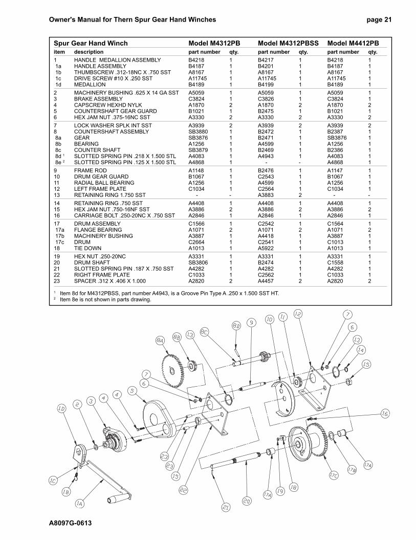
Spur Gear Hand Winch Model M4312PB Model M4312PBSS Model M4412PB
item description part number qty. part number qty. part number qty.
1 HANDLE MEDALLION ASSEMBLY B4218 1 B4217 1 B4218 1 1a HANDLE ASSEMBLY B4187 1 B4201 1 B4187 1 1b THUMBSCREW .312-18NC X .750 SST A8167 1 A8167 1 A8167 1 1c DRIVE SCREW #10 X .250 SST A11745 1 A11745 1 A11745 1 1d MEDALLION B4189 1 B4199 1 B4189 1
2 MACHINERY BUSHING .625 X 14 GA SST A5059 1 A5059 1 A5059 13 BRAKE ASSEMBLY C3824 1 C3826 1 C3824 14 CAPSCREW HEXHD NYLK A1870 2 A1870 2 A1870 25 COUNTERSHAFT GEAR GUARD B1021 1 B2475 1 B1021 16 HEX JAM NUT .375-16NC SST A3330 2 A3330 2 A3330 2
7 LOCK WASHER SPLK INT SST A3939 2 A3939 2 A3939 28 COUNTERSHAFT ASSEMBLY SB3880 1 B2472 1 B2387 1 8a GEAR SB3876 1 B2471 1 SB3876 1 8b BEARING A1256 1 A4599 1 A1256 1 8c COUNTER SHAFT SB3879 1 B2469 1 B2386 1 8d 1 SLOTTED SPRING PIN .218 X 1.500 STL A4083 1 A4943 1 A4083 1 8e 2 SLOTTED SPRING PIN .125 X 1.500 STL A4868 1 - - A4868 1
9 FRAME ROD A1148 1 B2476 1 A1147 110 DRUM GEAR GUARD B1067 1 C2543 1 B1067 111 RADIAL BALL BEARING A1256 1 A4599 1 A1256 112 LEFT FRAME PLATE C1034 1 C2564 1 C1034 113 RETAINING RING 1.750 SST - - A3883 2 - -
14 RETAINING RING .750 SST A4408 1 A4408 1 A4408 115 HEX JAM NUT .750-16NF SST A3886 2 A3886 2 A3886 216 CARRIAGE BOLT .250-20NC X .750 SST A2846 1 A2846 1 A2846 1
17 DRUM ASSEMBLY C1566 1 C2542 1 C1564 1 17a FLANGE BEARING A1071 2 A1071 2 A1071 2 17b MACHINERY BUSHING A3887 1 A4418 1 A3887 1 17c DRUM C2664 1 C2541 1 C1013 118 TIE DOWN A1013 1 A5922 1 A1013 1
19 HEX NUT .250-20NC A3331 1 A3331 1 A3331 120 DRUM SHAFT SB3806 1 B2474 1 C1558 121 SLOTTED SPRING PIN .187 X .750 SST A4282 1 A4282 1 A4282 122 RIGHT FRAME PLATE C1033 1 C2562 1 C1033 123 SPACER .312 X .406 X 1.000 A2820 2 A4457 2 A2820 2
1 Item 8d for M4312PBSS, part number A4943, is a Groove Pin Type A .250 x 1.500 SST HT.2 Item 8e is not shown in parts drawing.
Owner's Manual for Thern Spur Gear Hand Winchespage 22
A8097G-0613
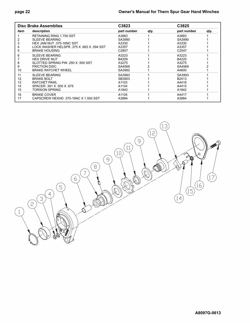
Disc Brake Assemblies C3823 C3825
item description part number qty. part number qty.
1 RETAINING RING 1.750 SST A3883 1 A3883 12 SLEEVE BEARING SA3990 1 SA3990 13 HEX JAM NUT .375-16NC SST A3330 1 A3330 14 LOCK WASHER HELSPR .375 X .683 X .094 SST A3357 1 A3357 15 BRAKE HOUSING C2807 1 C2547 1
6 SLEEVE BEARING A3223 1 A3223 17 HEX DRIVE NUT B4209 1 B4220 18 SLOTTED SPRING PIN .250 X .500 SST A3275 1 A3275 19 FRICTION DISC SA4569 2 SA4569 210 BRAKE RATCHET WHEEL SA3992 1 A4600 1
11 SLEEVE BEARING SA3993 1 SA3993 112 BRAKE BOLT SB3903 1 B2413 113 RATCHET PAWL A1103 1 A4416 114 SPACER .391 X .500 X .675 A1104 1 A4415 115 TORSION SPRING A1842 1 A1842 1
16 BRAKE COVER A1105 1 A4417 117 CAPSCREW HEXHD .375-16NC X 1.500 SST A3884 1 A3884 1
Owner's Manual for Thern Spur Gear Hand Winches page 23
A8097G-0613
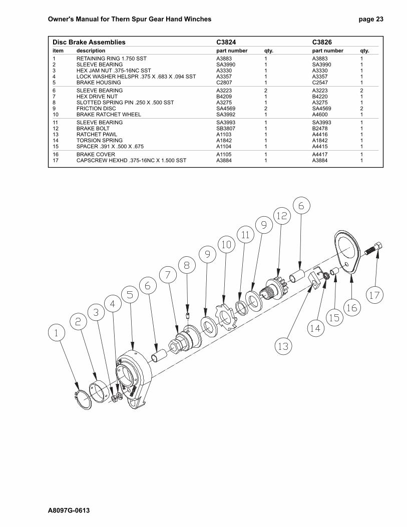
Disc Brake Assemblies C3824 C3826
item description part number qty. part number qty.
1 RETAINING RING 1.750 SST A3883 1 A3883 12 SLEEVE BEARING SA3990 1 SA3990 13 HEX JAM NUT .375-16NC SST A3330 1 A3330 14 LOCK WASHER HELSPR .375 X .683 X .094 SST A3357 1 A3357 15 BRAKE HOUSING C2807 1 C2547 1
6 SLEEVE BEARING A3223 2 A3223 27 HEX DRIVE NUT B4209 1 B4220 18 SLOTTED SPRING PIN .250 X .500 SST A3275 1 A3275 19 FRICTION DISC SA4569 2 SA4569 210 BRAKE RATCHET WHEEL SA3992 1 A4600 1
11 SLEEVE BEARING SA3993 1 SA3993 112 BRAKE BOLT SB3807 1 B2478 113 RATCHET PAWL A1103 1 A4416 114 TORSION SPRING A1842 1 A1842 115 SPACER .391 X .500 X .675 A1104 1 A4415 1
16 BRAKE COVER A1105 1 A4417 117 CAPSCREW HEXHD .375-16NC X 1.500 SST A3884 1 A3884 1

Thern, Incorporated
5712 Industrial Park Road
Winona, MN 55987
PHN 507-454-2996
FAX 507-454-5282
EMAIL: [email protected]
www.thern.com


![2013-2014 ANNUAL ASSESSMENT REPORT TEMPLATE...Chart 3 a. PLO 1: j Y b. PLO 1: v Y c. PLO 1: n Y d. PLO 1: te P Y g. LO 3: j Y h. LO 3: l]Y i. PLO 4: al Y) 1 0 0.51 0.51 0 0.51 0.51](https://img.pdfslide.us/doc/110x75/5f2cb7f173abf20ea42d8e53/2013-2014-annual-assessment-report-template-chart-3-a-plo-1-j-y-b-plo-1.jpg)