Embed Size (px)
Citation preview

08/04/15
Zero Clearance RoomSealed Gas Fireplace
FOR YOUR SAFETYWhat to do if you smell gas: Do not try to light any appli-
ance Do not touch any electri-
cal switch: do not use any phone in your building.
Immediately call your gas supplier from a neighbour's phone. Follow the gas sup-plier's instructions.
If you cannot reach your gas supplier, call the fire department.
WARNING: Improper installation, adjustment, altera-tion, service or maintenance can cause injury or property damage. Refer to this manual. For assistance or additional in-formation consult an authorized installer, service agency or the gas supplier.
FOR YOUR SAFETYDo not store or use gasoline or other flam-mable vapours and liquids in the vicinity of this or any other appliance.Installation and service must be performed by an authorized installer, service agency or the gas supplier.
PLEASE KEEP THESE INSTRUCTIONSFOR FUTURE REFERENCE
Owners &Installation
Man
ual
LISTINGS AND CODE APPROVALS
These gas appliances have been tested in accordance with AS4553, NZS 5262 and have been certified by the Australian Gas Association for installation and op-eration as described in these Installation and Operating Instructions.
Your unit should be serviced annu-ally by an authorised service person.
918-648d
STYLE MODEL See Thru PG121-NG1 PG121-LPG1Left Corner PG121LC-NG1 PG121LC-LPG1Right Corner PG121RC-NG1 PG121RC-LPG1Pier PG131-NG1 PG131-LPG1

Regency PG121/PG131 Zero Clearance Room Sealed Gas Fireplace2
To the New Owner:
Congratulations!
You are the owner of a state-of-the-art Gas Fireplace by REGENCY. The PG121-1 / PG121LC-1 / PG121RC-1 / PG131-1 has been designed to provide you with all the warmth and charm of a wood fireplace at the flick of a switch. The model PG121-1 / PG121LC-1 / PG121RC-1 / PG131-1 has been approved by the Australian Gas Association for both safety and efficiency. As it also bears our own mark, it promises to provide you with economy, comfort and security for many trouble free years to follow. Please take a moment now to acquaint yourself with these instructions and the many features of your Regency Fireplace.
IMPORTANT:If the unit is to be installed into a bathroom, optional Neo ceramic glass Part# 360-946 (Front) or Part# 360-948 (Side) must be purchased and installed in place of the tempered glass supplied with the unit.
Regency PG121/PG131 Zero Clearance Room Sealed Gas Fireplace 3
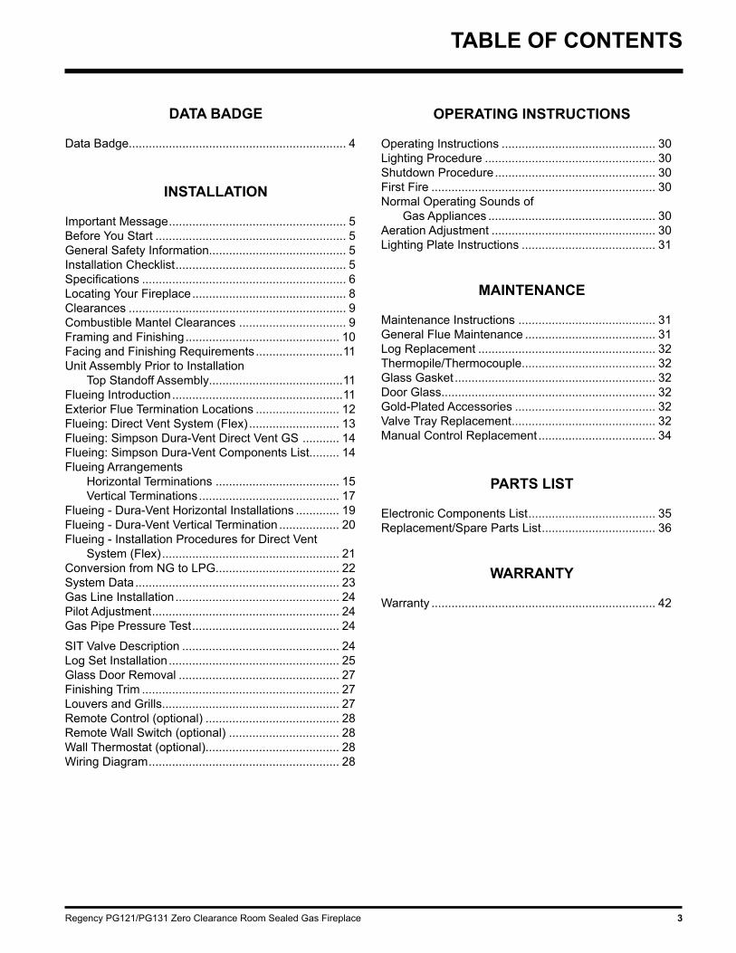
TABLE OF CONTENTS
OPERATING INSTRUCTIONS
Operating Instructions .............................................. 30Lighting Procedure ................................................... 30Shutdown Procedure ................................................ 30First Fire ................................................................... 30Normal Operating Sounds of Gas Appliances .................................................. 30Aeration Adjustment ................................................. 30Lighting Plate Instructions ........................................ 31
MAINTENANCE
Maintenance Instructions ......................................... 31General Flue Maintenance ....................................... 31Log Replacement ..................................................... 32Thermopile/Thermocouple........................................ 32Glass Gasket ............................................................ 32Door Glass................................................................ 32Gold-Plated Accessories .......................................... 32Valve Tray Replacement ........................................... 32Manual Control Replacement ................................... 34
PARTS LIST
Electronic Components List ...................................... 35Replacement/Spare Parts List .................................. 36
WARRANTY Warranty ................................................................... 42
DATA BADGE
Data Badge................................................................. 4
INSTALLATION
Important Message ..................................................... 5Before You Start ......................................................... 5General Safety Information......................................... 5Installation Checklist ................................................... 5Specifications ............................................................. 6Locating Your Fireplace .............................................. 8Clearances ................................................................. 9Combustible Mantel Clearances ................................ 9Framing and Finishing .............................................. 10Facing and Finishing Requirements ..........................11Unit Assembly Prior to Installation Top Standoff Assembly........................................11Flueing Introduction ...................................................11Exterior Flue Termination Locations ......................... 12Flueing: Direct Vent System (Flex) ........................... 13Flueing: Simpson Dura-Vent Direct Vent GS ........... 14Flueing: Simpson Dura-Vent Components List......... 14Flueing Arrangements Horizontal Terminations ..................................... 15 Vertical Terminations .......................................... 17Flueing - Dura-Vent Horizontal Installations ............. 19Flueing - Dura-Vent Vertical Termination .................. 20Flueing - Installation Procedures for Direct Vent System (Flex) ..................................................... 21Conversion from NG to LPG..................................... 22System Data ............................................................. 23Gas Line Installation ................................................. 24Pilot Adjustment ........................................................ 24Gas Pipe Pressure Test ............................................ 24
SIT Valve Description ............................................... 24Log Set Installation ................................................... 25Glass Door Removal ................................................ 27Finishing Trim ........................................................... 27Louvers and Grills..................................................... 27Remote Control (optional) ........................................ 28Remote Wall Switch (optional) ................................. 28Wall Thermostat (optional)........................................ 28Wiring Diagram ......................................................... 28

Regency PG121/PG131 Zero Clearance Room Sealed Gas Fireplace4
SAFETY LABEL
This is a copy of the label that accompanies each PG121-1 / PG121LC-1 / PG121RC-1 / PG131-1 Zero Clearance Room Sealed Gas Fireplace. We have printed a copy of the contents here for your review. The safety label is located on the front inside base of the unit, visible when the bottom louver is open.
NOTE: Regency units are constantly being improved. Check the label on the unit and if there is a difference, the label on the unit is the correct one.

Regency PG121/PG131 Zero Clearance Room Sealed Gas Fireplace 5
INSTALLATION
INSTALLATION CHECKLIST
1) Locate appliance; a) Room location b) Clearances to Combustibles c) Mantle Clearances d) Framing & Finishing Requirements e) Flueing Requirements
2) Assemble Top Standoffs. (NOTE: must be done before installing unit into fireplace.)
3) Install flue.
4) Make gas connections. Test the pilot. Must be as per diagram in "Pilot Adjustment" section.
5) Install log set.
6) Install Glass Door, Louvers or Grills , and Finishing Trim.
7) Final check.
Before leaving this unit with the customer, the installer must ensure that the appliance is firing correctly and operation fully explained to customer.
This includes:
1) Clocking the appliance to ensure the correct firing rate (rate noted on label 40,000 Btu/h NG, and 39,000 Btu/h LPG) after burning appliance for 15 minutes.
2) If required, adjusting the primary air to ensure that the flame does not carbon. First allow the unit to burn for 15-20 min. to stabilize.
CAUTION: Any alteration to the product that causes sooting or carboning that results in damage is not the responsibility of the manufacturer.
IMPORTANT: SAVE THESE
INSTRUCTIONSThe Regency PG121/PG121LC/PG121RC/PG131-NG1 or PG121/PG121LC/PG121RC/PG131-LPG1 Room Sealed Gas Fireplace must be installed in accordance AG601 and NZS 5261 and with these instructions. Carefully read all the instructions in this manual first. Consult the "authority having jurisdiction" to determine the need for a permit prior to starting the installation. It is the responsibility of the installer to ensure this fireplace is installed in compliance with manu-facturer's instructions and all applicable codes.
BEFORE YOU STARTSafe installation and operation of this appliance requires common sense, however, we are required to make you aware of the following:
GENERAL SAFETYINFORMATION
1) The appliance shall be installed in accord-ance with the manufacturer's installation instructions, local gas fitting regulations, municipal building codes, water supply regulations, electrical wiring regulations, with AS5601-2004 (AGA gas installation code) NZS 5261 (New Zealand)
2) See general construction and assembly instructions. The appliance and flue should be enclosed.
3) This appliance must be connected to the specified flue and termination cap to the outside of the building envelope. Never flue to another room or inside a building. Make sure that the flue is fitted as per Flueing instructions.
4) Inspect the flueing system annually for blockage and any signs of deterioration.
5) Flueing terminals shall not be recessed into a wall or siding.
6) Any safety glass removed for servicing must be replaced prior to operating the appliance.
7) To prevent injury, do not allow anyone who is unfamiliar with the operation to use the fireplace.
8) Wear gloves and safety glasses for protec-tion while doing required maintenance.
9) Be aware of electrical wiring locations in walls and ceilings when cutting holes for termination.
10) Under no circumstances should this ap-pliance be modified. Parts that have to be removed for servicing should be replaced prior to operating this appliance.
11) Installation and any repairs to this appliance should be done by a authorized service person. A authorized service person should be called to inspect this appliance annually. Make it a practice to have all of your gas appliances checked annually.
12) Do not slam shut or strike the glass door.
13) Under no circumstances should any solid fuels (wood, paper, cardboard, coal, etc.) be used in this appliance.
14) The appliance area must be kept clear and
INSTALLATION AND REPAIR SHOULD BE DONE BY A AUTHORIZED SERVICE PERSON. THE APPLIANCE SHOULD BE INSPECTED BEFORE USE AND AT LEAST ANNUALLY BY A AUTHORIZED SERVICE PERSON. MORE FREQUENT CLEANING MAY BE REQUIRED DUE TO EXCESSIVE LINT FROM CAR-PETING, BEDDING MATERIAL, ETC. IT IS IMPERATIVE THAT CONTROL COMPARTMENTS, BURNERS AND CIRCULATING AIR PASSAGEWAYS OF THE APPLIANCE BE KEPT CLEAN.
DUE TO HIGH TEMPERATURES, THE APPLIANCE SHOULD BE LOCATED OUT OF TRAFFIC AND AWAY FROM FURNITURE AND DRAPERIES.
WARNING: FAILURE TO INSTALL THIS APPLIANCE CORRECTLY WILL VOID YOUR WARRANTY AND MAY CAUSE A SERIOUS HOUSE FIRE.
CLOTHING OR OTHER FLAMMABLE MATERIAL SHOULD NOT BE PLACED ON OR NEAR THE APPLIANCE.
CHILDREN AND ADULTS SHOULD BE ALERTED TO THE HAZARDS OF HIGH SURFACE TEMPERATURES, ES-PECIALLY THE FIREPLACE GLASS, AND SHOULD STAY AWAY TO AVOID BURNS OR CLOTHING IGNITION.
YOUNG CHILDREN SHOULD BE CAREFULLY SUPERVISED WHEN THEY ARE IN THE SAME ROOM AS THE APPLIANCE. Emissions from burning wood or gas could
contain chemicals known to the State of Cali-fornia to cause cancer, birth defects or other reproductive harm.
NOTE:Not intended forfireplace insert.
These units arenon-load bearing.
free of combustible materials, (gases and other flammable vapours and liquids).

Regency PG121/PG131 Zero Clearance Room Sealed Gas Fireplace6
INSTALLATION
SPECIFICATIONS
PG121-1 - See Thru
PG131-1 - Pier
Note: These units are non-load bearing.

Regency PG121/PG131 Zero Clearance Room Sealed Gas Fireplace 7
PG121LC-1 - Left Corner Unit
PG121RC-1 - Right Corner Unit
INSTALLATION
Note: These units are non-load bearing.
Regency PG121/PG131 Zero Clearance Room Sealed Gas Fireplace8
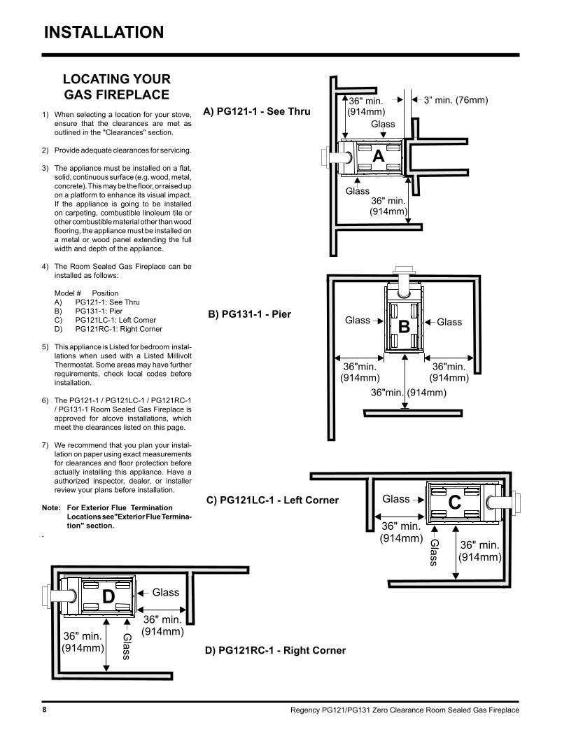
LOCATING YOUR GAS FIREPLACE
1) When selecting a location for your stove, ensure that the clearances are met as outlined in the "Clearances" section.
2) Provide adequate clearances for servicing.
3) The appliance must be installed on a flat, solid, continuous surface (e.g. wood, metal, concrete). This may be the floor, or raised up on a platform to enhance its visual impact. If the appliance is going to be installed on carpeting, combustible linoleum tile or other combustible material other than wood flooring, the appliance must be installed on a metal or wood panel extending the full width and depth of the appliance.
4) The Room Sealed Gas Fireplace can be installed as follows:
Model # Position A) PG121-1: See Thru B) PG131-1: Pier C) PG121LC-1: Left Corner D) PG121RC-1: Right Corner
5) This appliance is Listed for bedroom instal-lations when used with a Listed Millivolt Thermostat. Some areas may have further requirements, check local codes before installation.
6) The PG121-1 / PG121LC-1 / PG121RC-1 / PG131-1 Room Sealed Gas Fireplace is approved for alcove installations, which meet the clearances listed on this page.
7) We recommend that you plan your instal-lation on paper using exact measurements for clearances and floor protection before actually installing this appliance. Have a authorized inspector, dealer, or installer review your plans before installation.
Note: For Exterior Flue Termination Locations see"Exterior Flue Termina-
tion" section..
INSTALLATION
A) PG121-1 - See Thru
B) PG131-1 - Pier
C) PG121LC-1 - Left Corner
D) PG121RC-1 - Right Corner

Regency PG121/PG131 Zero Clearance Room Sealed Gas Fireplace 9
INSTALLATION
COMBUSTIBLE MANTELS
CLEARANCESThe clearances listed below are Minimum distances unless otherwise stated (refer to diagrams in "Locating Your Gas Fireplace" section):
WARNING: Fire hazard is an extreme risk if these clearances (air space) to combustible materials are
not adhered to. It is of greatest importance that this fireplace and flue system be installed
only in accordance with these instructions.
Clearance to Combustibles from: Back 0" (0mm) Side 0" (0mm) Floor 0" (0mm)
CAUTION REQUIREMENTS: The top, back and sides of the fireplace are defined by standoffs. The metal ends of the standoffs may NOT be recessed into combustible construction.
Determine the total thickness of the finished floor (eg. tile, carpet, slate) to allow the finished surface to be flush with the base of the unit.
Ceiling Height from Floor 72" (1828mm)
Mantel Height from Base of Unit: 39" min. (991mm)
Horizontal Flue Clearances: Top 2-1/2" (64mm) Side 1-1/2" (38mm) Bottom 1-1/2" (38mm)
Vertical Flue Clearances 1-1/4" (32mm)
Due to the extreme heat this fireplace emits, the mantel clearances are critical. Combustible mantel clearances from top of unit are shown in Diagram to the right.
Note: A non-combustible mantel may be installed at a lower height if the framing is made of metal studs covered with a non-combustible board.
This drawing is to scale at 1:6 (one inch = 6 inches)Mantel can be installed anywhere in shaded area or higher using this scale.
Caution: Ensure the paint that is used on the mantel and the facing is "heat resistant" or the paint may discolour.
* If the 3" (76mm) metal extension trim is removed it must be replaced with a 8" (203mm) non-combustible material.
Mantel Clearances

Regency PG121/PG131 Zero Clearance Room Sealed Gas Fireplace10
FRAMING AND FINISHING
CAUTION: The unit does not have to be completely enclosed in a chase. The clearance on top of the unit is 0" to the standoffs so combustible building materials can be laid directly on top of the standoffs. You must maintain clearance from the flue to combustible materials for both rigid and flex.
PG121-1 - See Thru
PG131-1 - Pier
Framing Dimensions PG121 (See Thru) PG131 (Pier) PG121LC / PG121RC (Corner Unit)
A 25"(635mm) 25"(635mm) 26-13/13"(660mm) minus two times minus two times minus two times the finishing the finishing the finishing material thickness* material thickness* material thickness*
B 42-1/2"(1080mm) 42-1/2"(1080mm) 42-1/2"(1080mm) C 46-3/4"(1187mm) 45" (1143mm) 45"(1143mm) minus one time minus one time the finishing the finishing material thickness* material thickness*
Note: These units are non-load bearing.
PG121LC-1 - Corner Unit
* Finish material thickness includes: drywall, ceramic tile, slate, etc.
1) For ease of installation, frame your fireplace after it is positioned and the flue system is installed. Remember to install the top standoffs. Use 2x4's and frame to local building codes.
2) When locating your appliance on an exterior wall or in a chase, apply a vapour barrier and drywall, as per local building codes. DO NOT INSULATE THE FIREPLACE ITSELF.
CAUTION: Verify your fireplace dimensions, framing methods and finished wall facing details before framing. Determine the total thick-ness of facing material - drywall plus ceramic tiles, slate, etc. Allow the finish surface to be flush with the front or side of the unit. Total facing thickness can vary from 1/2" (13mm) to 1-1/4" (32mm) thick.
PG121RC-1 - Corner Unit
INSTALLATION

Regency PG121/PG131 Zero Clearance Room Sealed Gas Fireplace 11
FLUEING INTRODUCTION
The PG121-1 / PG121LC-1 / PG121RC-1 / PG131-1 uses the "balanced flue" technology Co Axial system. The inner liner flue products of combustion to the outside while the outer liner draws outside combustion air into the combus-tion chamber thereby eliminating the need to use heated room air for combustion and losing warm room air up the chimney.
Note: Thesefluepipesmustnotbecon-nectedtoanyotherappliance.
The gas appliance and flue system must be flueed directly to the outside of the building, and never be attached to a chimney serving a separate solid fuel or gas burning appliance. Each direct flue gas appliance must use it's own separate flue system. Common flue systems are prohibited.
INSTALLATION
UNIT ASSEMBLY PRIOR TO
INSTALLATIONThe 4 Top Standoffs must be correctly positioned and attached to the top before unit is slipped into position.
Top Standoff Assembly
The top standoffs are shipped in a flat position and must be folded into shape and attached.
1) Remove the standoffs from the fireplace top.
2) Take each standoff and bend into the cor-rect shape. Bend up at the bend lines until the screw holes in the standoff and the pre-punched screw holes on the fireplace top line up.
3) Attach the standoff securely to the top with 4 screws per standoff (on opposite corners).
FACING & FINISHING REQUIREMENTSThis fireplace is supplied with a 3" metal extension trim above the fireplace. The extension trim may be replaced if the framing is faced with a non-combustible material placed flush with the front and side face of the unit and extending from the top of the unit. (ie. tile, slate, etc.)

Regency PG121/PG131 Zero Clearance Room Sealed Gas Fireplace12
INSTALLATION
EXTERIOR FLUE TERMINATION LOCATIONS
Minimum clearances required for balanced flue terminals or the flue terminals of outdoor appliances
according to AS5601-2004 (AGA gas installation code) or NZS 5261 (New Zealand)
Minimum Clearance (mm)a Below eaves, balconies or other projections: - Appliances up to 50 MJ/h input 300 - Appliances over 50 MJ/h input 500b From the ground or above a balcony 300c From a return wall or external corner 500d From a gas meter (M) 1000e From an electricity meter or fuse box (P) 500f From a drain or soil pipe 150g Horizontal from any building structure (unless appliance is approved for closer installation) or obstruction facing a terminal 500h From any other flue terminal, cowl or combustion air intake 500j Horizontally from an openable window, door, or non-mechanical air inlet, or any other opening into a building, with the exception of sub-floor ventilation (see also Note (I)): - Appliances up to 150 MJ/h input 500 - Appliances over 150 MJ/h input 1500k Vertically below an openable window, door, or non-mechanical air inlet, or any other opening into a building, with the exception of sub-floor ventilation (see also Note (I)): see table below
Clearance 'k' in mmSpace Heaters All Other Appliances
Up to 50 MJ/h Up to 50 MJ/h input Over 50 MJ/h input Over 150 MJ/h input
input to 150 MJ/h input
150 500 1000 1500
NOTES:
(I) For mechanical air inlets, including spa blowers, the clearance 'j' and 'k' shall be 1500 mm in all cases.
(II) All distances shall be measured vertically or horizontally along the wall to a point in line with the nearest par to of the terminal.
(III) Prohibited area below electricity meter or fuse box extends to ground level.
(IV) A flue terminal of this type shall not be located under a roofed area unless the roofed area is fully open on at least two sides and a
free flow of air at the appliance is achieved.

Regency PG121/PG131 Zero Clearance Room Sealed Gas Fireplace 13
23
FLUEING ARRANGEMENT - HORIZONTAL TERMINATIONSRegencyDirectVentSystem(Flex)HorizontalTerminationsOnly
These flueing systems, in combination with the PG121-1 / PG121LC-1 / PG121RC-1 / PG131-1 Direct Vent Gas Fireplace, have been tested and listed as a direct flue heater system by Warnock Hersey. The location of the termination cap must conform to the requirements in the Flue Terminal Locations diagram.
Regency Direct Vent (Flex) System Termination Kit (Part# 946-513) includes all the parts needed to install the PG121-1 / PG121LC-1 / PG121RC-1 / PG131-1 with a maximum run of 2 feet.
1) 6-7/8" dia. flexible liner (2 ft. length)2) 4" dia. flexible liner (2 ft. length)3) spring spacers (3)4) thimble (2)5) AstroCap termination cap (1)6) screws (12)7) tube of Mill Pac (1)8) plated screws (8)9) screws #8 x 1-1/2" drill point, stainless steel (4)
Notes: 1) Liner sections should be continuous without any joints or seams.
2) Only Flex pipe purchased from Regency may be used for Flex installations.
3) Regency Direct Vent System (Flex) is only approved for horizontal terminations.
INSTALLATION
Regency PG121/PG131 Zero Clearance Room Sealed Gas Fireplace14
Simpson Dura-VentDirect Vent GS
SIMPSON DURA-VENT FLUEING COMPONENTS LISTAll Simpson Dura-Vent components are available directly from Regency.
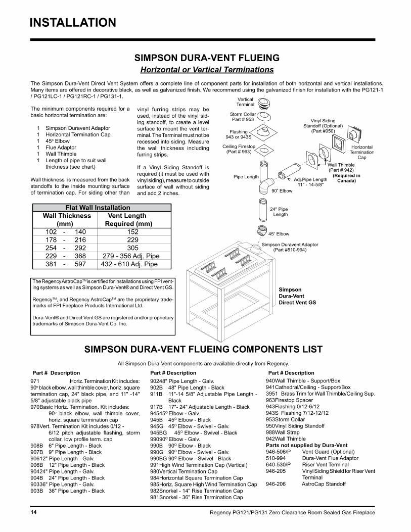
SIMPSON DURA-VENT FLUEINGHorizontalorVerticalTerminations
The Simpson Dura-Vent Direct Vent System offers a complete line of component parts for installation of both horizontal and vertical installations. Many items are offered in decorative black, as well as galvanized finish. We recommend using the galvanized finish for installation with the PG121-1 / PG121LC-1 / PG121RC-1 / PG131-1.
The minimum components required for a basic horizontal termination are:
1 Simpson Duravent Adaptor 1 Horizontal Termination Cap 1 45o Elbow 1 Flue Adaptor 1 Wall Thimble 1 Length of pipe to suit wall thickness (see chart)
Wall thickness is measured from the back standoffs to the inside mounting surface of termination cap. For siding other than
971 Horiz. Termination Kit includes: 90o black elbow, wall thimble cover, horiz. square termination cap, 24" black pipe, and 11" -14" 5/8" adjustable black pipe970 Basic Horiz. Termination. Kit includes: 90o black elbow, wall thimble cover,
horiz. square termination cap 978 Vert. Termination Kit includes 0/12 - 6/12 pitch adjustable flashing, storm
collar, low profile term. cap908B 6" Pipe Length - Black 907B 9" Pipe Length - Black 906 12" Pipe Length - Galv.906B 12" Pipe Length - Black 904 24" Pipe Length - Galv.904B 24" Pipe Length - Black 903 36" Pipe Length - Galv. 903B 36" Pipe Length - Black
902 48" Pipe Length - Galv.902B 48" Pipe Length - Black 911B 11"-14 5/8" Adjustable Pipe Length -
Black 917B 17"- 24" Adjustable Length - Black 945 45O Elbow - Galv.945B 45O Elbow - Black 945G 45O Elbow - Swivel - Galv.945BG 45O Elbow - Swivel - Black 990 90O Elbow - Galv.990B 90O Elbow - Black 990G 90O Elbow - Swivel - Galv.990BG 90O Elbow - Swivel - Black 991 High Wind Termination Cap (Vertical)980 Vertical Termination Cap984 Horizontal Square Termination Cap985 Horiz. Square High Wind Termination Cap982 Snorkel - 14" Rise Termination Cap981 Snorkel - 36" Rise Termination Cap
940 Wall Thimble - Support/Box 941 Cathedral/Ceiling - Support/Box3951 Brass Trim for Wall Thimble/Ceiling Sup.963 Firestop Spacer943 Flashing 0/12-6/12943S Flashing 7/12-12/12953 Storm Collar950 Vinyl Siding Standoff988 Wall Strap 942 Wall ThimbleParts not supplied by Dura-Vent946-506/P Vent Guard (Optional)510-994 Dura-Vent Flue Adaptor640-530/P Riser Vent Terminal946-205 Vinyl Siding Shield for Riser Vent
Terminal946-206 AstroCap Standoff
vinyl furring strips may be used, instead of the vinyl sid-ing standoff, to create a level surface to mount the vent ter-minal. The Terminal must not be recessed into siding. Measure the wall thickness including furring strips.
If a Vinyl Siding Standoff is required (it must be used with vinyl siding), measure to outside surface of wall without siding and add 2 inches.
Part # Description Part # Description Part # Description
INSTALLATION
Flat Wall Installation Wall Thickness Vent Length (mm) Required (mm) 102 - 140 152 178 - 216 229 254 - 292 305 229 - 368 279 - 356 Adj. Pipe 381 - 597 432 - 610 Adj. Pipe
The Regency AstroCapTM is certified for installations using FPI vent-ing systems as well as Simpson Dura-Vent® and Direct Vent GS.
RegencyTM, and Regency AstroCapTM are the proprietary trade-marks of FPI Fireplace Products International Ltd.
Dura-Vent® and Direct Vent GS are registered and/or proprietary trademarks of Simpson Dura-Vent Co. Inc.

Regency PG121/PG131 Zero Clearance Room Sealed Gas Fireplace 15
INSTALLATION
FLUEING ARRANGEMENTS - HORIZONTAL TERMINATIONSSIMPSONDURA-VENTDIRECTVENTGSSYSTEM
The diagram below shows examples of horizontal termination arrangements using one, two, or three 90o elbows (two 45o elbows equal one 90o elbow).
Note: 1) A maximum of three 90o elbows are permitted. 2) Minimum distance between elbows is 1 ft. (305mm).
• Maintain clearances to combustibles.• Horizontal flue must be supported every 3 feet.• Firestops are required at each floor level and whenever passing through a wall.• Must use optional flue adapter (Part# 510-994) when using Simpson Dura-Vent pipe.• A vent guard should be used whenever the termination is lower than the specified minimum or as per local codes.
SimpsonDura-Vent4"innerdiameter6-5/8"outerdiameter
Straight Out Horizontal Flueing Horizontal Flueing with One (1) 90o Elbow
Option V H A) 1' (305mm) Minimum 3' (914mm) Maximum B) 2' (610mm) Minimum 6' (1.86m) Maximum C) 3' (914mm) Minimum 9' (2.7m) Maximum D) 4' (1.22m) Minimum 12' (3.6m) Maximum E) 5' (1.5m) Minimum 15' (4.5m) Maximum F) 6' (1.86m) Minimum 17' (5.1m) Maximum
Diagram 1
Diagram 2
With the above options, maximum total pipe length if 37 feet with minimum of 6 feet total vertical and maximum 17 feet total horizontal.Pleasenoteminimum1footbetween90oelbowsisrequired.
Pleasenotetheminimumcenterlineforbasicinstallshownabove.

Regency PG121/PG131 Zero Clearance Room Sealed Gas Fireplace16
INSTALLATION
Diagram 3
Horizontal Flueing with Two (2) 90o Elbows
Option V H + H1 A) 1' (305mm) Minimum 2' (610mm) Maximum B) 2' (610mm) Minimum 5' (1.5m) Maximum C) 3' (914mm) Minimum 8' (2.4m) Maximum D) 4' (1.22m) Minimum 11' (3.35m) Maximum E) 5' (1.5m) Minimum 14' (4.27m) Maximum F) 6' (1.86m) Minimum 15' (4.5m) Maximum
Horizontal Flueing with Two (2) 90o Elbows
Option V H H + H1 A) 1' (305mm) Min. 1' (305mm) Max. 3' (914mm) Max. B) 2' (610mm) Min. 3' (0.91m) Max. 6' (1.86m) Max. C) 3' (914mm) Min. 5' (1.5m) Max. 9' (2.7m) Max. D) 5' (1.5m) Min. 8' (2.4m) Max. 12' (3.6m) Max.
Horizontal Flueing with Three (3) 90o Elbows
Horizontal Flueing with Three (3) 90o Elbows
Diagram 5
Diagram 4 Diagram 6
With the above options, maximum total pipe length if 37 feet with minimum of 6 feet total vertical and maximum 15 feet total horizontal.Pleasenoteminimum1footbetween90oelbowsisrequired.
Option V H H + H1 + H2 A) 2' (610mm) Min. 1' (305mm) Max. 3' (914mm) Max. B) 3' (914mm) Min. 3' (914mm) Max. 6' (1.86m) Max. C) 4' (1.22mm) Min. 5' (1.5m) Max. 9' (2.7m) Max. D) 5' (1.5m) Min. 7' (2.13m) Max. 12' (3.6m) Max.
With the above options, maximum total pipe length if 37 feet with minimum of 5 feet total vertical and maximum 12 feet total horizontal.Pleasenoteminimum1footbetween90oelbowsisrequired.
With the above options, maximum total pipe length if 37 feet with minimum of 5 feet total vertical and maximum 12 feet total horizontal.Pleasenoteminimum1footbetween90oelbowsisrequired.
Option V + V1 H + H1 A) 2' (610mm) Minimum 3' (914mm) Maximum B) 3' (914mm) Minimum 6' (1.86m) Maximum C) 4' (1.22m) Minimum 9' (2.7m) Maximum D) 5' (1.5m) Minimum 12' (3.6m) MaximumWith the above options, maximum total pipe length if 37 feet with minimum of 5 feet total vertical and maximum 12 feet total horizontal.Pleasenoteminimum1footbetween90oelbowsisrequired.

Regency PG121/PG131 Zero Clearance Room Sealed Gas Fireplace 17
INSTALLATION
FLUEING ARRANGEMENTS - VERTICAL TERMINATIONSSIMPSONDURA-VENTDIRECTVENTGSSYSTEM
• Flue must be supported at offsets• Maintain clearances to combustibles.• Firestops are required at each floor level and whenever passing through a wall.• Must use optional flue adapter when using Simpson Dura-Vent pipe (Part# 510-994).
The PG121-1 / PG121LC-1 / PG121RC-1 / PG131-1 is approved for a maximum 35 ft. (10.7m) straight vertical, with Simpson Dura-Vent Direct Vent GS flue systems for LPG and NG.
Diagram 7
Diagram 8
Straight Up Vertical Flueing Vertical Flueing with One (1) 90o ElbowOption V H A) 1' (305mm) Minimum 2' (610mm) Maximum B) 2' (610mm) Minimum 4' (1.22m) Maximum C) 3' (914mm) Minimum 6' (1.86m) Maximum D) 4' (1.22m) Minimum 8' (2.4m) Maximum
With the above options, maximum total pipe length if 37 feet with minimum of 4 feet total vertical and maximum 8 feet total horizontal.Pleasenoteminimum1footbetween90oelbowsisrequired.

Regency PG121/PG131 Zero Clearance Room Sealed Gas Fireplace18
INSTALLATION
Vertical Flueing with Two (2) 90o Elbows
Option V H A) 1' (305mm) Minimum 4' (1.22m) Maximum B) 2' (610mm) Minimum 6' (1.86m) Maximum C) 3' (914mm) Minimum 9' (2.7m) Maximum D) 4' (1.22m) Minimum 12' (3.6m) Maximum E) 5' (1.5m) Minimum 15' (4.5m) Maximum F) 6' (1.86m) Minimum 17' (5.1m) Maximum
Vertical Flueing with Two (2) 90o Elbows
Vertical Flueing with Three (3) 90o Elbows
Diagram 9Diagram 10
Diagram 11
Option V + V1 H H + H1 A) 2' (610mm) Min. 1' (305mm) Max. 2' (610mm) Max. B) 3' (914mm) Min. 4' (1.22m) Max. 5' (1.5m) Max. C) 4' (1.22mm) Min. 6' (1.86m) Max. 8' (2.4m) Max. D) 5' (1.5m) Min. 8' (2.4m) Max. 12' (3.6m) Max.
With the above options, maximum total pipe length if 37 feet with minimum of 6 feet total vertical and maximum 17 feet total horizontal.Pleasenoteminimum1footbetween90oelbowsisrequired.
Option V H + H1 A) 1' (305mm) Minimum 2' (610mm) Maximum B) 2' (610mm) Minimum 4' (1.22m) Maximum C) 3' (914mm) Minimum 6' (1.86m) Maximum D) 4' (1.22m) Minimum 8' (2.4m) Maximum
With the above options, maximum total pipe length if 37 feet with minimum of 4 feet total vertical and maximum 8 feet total horizontal.Pleasenoteminimum1footbetween90oelbowsisrequired.
With the above options, maximum total pipe length if 37 feet with minimum of 5 feet total vertical and maximum 12 feet total horizontal.Pleasenoteminimum1footbetween90oelbowsisrequired.

Regency PG121/PG131 Zero Clearance Room Sealed Gas Fireplace 19
INSTALLATION
HORIZONTAL INSTALLATIONS
Install the flue system according to the manufacturer's instructions included with the components.
1) Set the unit in its desired location. Check to determine if wall studs or roof rafters are in the way when the flueing system is attached. If this is the case, you may want to adjust the location of the unit. Rough in the gas.
2) Direct Flue pipe and fittings are designed with special twist-lock connections to connect the flueing system to the appliance flue outlet. A twist-lock appliance adaptor is an available option that must be used in conjunction with the Simpson Dura-Vent Direct Vent GS system.
3) Put a bead of silicone inside the outer section of the adapter and a bead of Mill Pac on the inner collar. Slip the adapter over the existing inner and outer flue collar and fasten to the outer collar only with the 3 supplied screws (drilling pilot holes will make this easier). Level the fireplace and fasten it to the fram-ing using nails or screws through the nailing strips.
4) Assemble the desired combination of pipe and elbows to the appliance adaptor and twist-lock for a solid connection.
Note: a) Twist-lock procedure: Four indentations,
located on the female ends of pipes and fittings, are designed to slide straight onto the male ends of adjacent pipes and fittings, by orienting the four pipe indentations so they match and slide in to the four entry slots on the male ends, Diagram 1. Push the pipe sections completely together, then twist-lock
Diagram 1
ported every three feet. Wall straps are available for this purpose.
5) Mark the wall for a 10" x 10" square hole. The center of the square hole should line up with the centerline of the horizontal pipe. Cut and frame the 10 inch square hole in the exterior wall where the flue will be terminated. If the wall being penetrated is constructed of non-combustible material, i.e. masonry block or concrete, a 7"(178mm) dia. (7-1/2"(191mm) dia. for flex) hole is acceptable.
Note: With Dura-Vent, the minimum height is achieved by installing a 45o elbow directly to the flue adaptor.
Note: a) The horizontal run of flue must be level,
or have a 1/4 inch rise for every 1 foot of run towards the termination. Never allow the flue to run downward. This
Diagram 2
could cause high temperatures and may present the possibility of a fire.
b) The location of the horizontal flue termi-nation on an exterior wall must meet all local and national building codes, and must not be blocked or obstructed. For External Flue Terminal Locations, see diagram on page 12.
6) The arrow on the flue cap should be point-ing up. Insure that the 1-1/2" clearances to combustible materials are maintained (Diagram 3 on page 16). Install the termina-tion cap.
The four wood screws provided should be replaced with appropriate fasteners for stucco, brick, concrete, or other types of sidings.
Note: If installing termination on a siding covered wall, a vinyl siding standoff or furring strips must be used to ensure that the termination is not recessed into the siding.
7) Before connecting the horizontal run of flue
Note: Apply sealant "Mill-Pac" to inner pipe and high temperature silicone sealant to outer pipe on every twist-lock joint.
b) Horizontal runs of flue must be sup-
Diagram 12
Vertical Flueing with Three (3) 90o Elbows
Option V + V1 H + H1 A) 2' (610mm) Minimum 3' (914mm) Maximum B) 3' (914mm) Minimum 6' (1.86m) Maximum C) 4' (1.22m) Minimum 9' (2.7m) Maximum D) 5' (1.5m) Minimum 12' (3.6m) Maximum
one section clockwise approximately one-quarter turn, until the two sections are fully locked. The female locking lugs will not be visible from the outside, on the Black Pipe or fittings. They may be located by examining the inside of the female ends.
With the above options, maximum total pipe length if 37 feet with minimum of 5 feet total vertical and maximum 12 feet total horizontal.Pleasenoteminimum1footbetween90oelbowsisrequired.

Regency PG121/PG131 Zero Clearance Room Sealed Gas Fireplace20
Diagram 3
Diagram 5
Diagram 1
Diagram 2
Note: Apply sealant "Mill-Pac" to inner pipe and high temperature silicone seal-ant to outer pipe on every twist-lock joint.
TERMINATION1) Maintain the 1-1/4" clearances (air spaces)
to combustibles when passing through ceil-ings, walls, roofs, enclosures, attic rafter, or other nearby combustible surfaces. Do not pack air spaces with insulation. Check pages 17-19 for the maximum vertical rise of the flueing system and the maximum horizontal offset limitations.
2) Set the gas appliance in its desired location. Drop a plumb bob down from the ceiling to the position of
in the ceiling, and mark the spot where the flue will penetrate the roof. Determine if ceil-ing joists, roof rafters or other framing will obstruct the flueing system. You may wish to relocate the appliance or to offset, as shown in Diagram 2 to avoid cutting load bearing members.
3) A F i r e s t o p spacer must be installed in the floor or ceiling of every level. To install the Firestop spacer
in a flat ceiling or wall, cut a 10 inch square hole. Frame the hole as shown in Diagram 3 and install the firestop.
4) Assemble the desired lengths of pipe and elbows. Ensure that all pipes and elbow con-
nections are in the fully twist-locked position and sealed.
5) Cut a hole in the roof centered on the small drilled hole placed in the roof in Step 2. The hole should be of sufficient size to meet the minimum requirements for clearance to combustibles of 1-1/4". Slip the flashing under the shingles (shingles should overlap half the flashing) as per Diagram 4.
6) Continue to assemble pipe lengths.
Roof Pitch Minimum Vent Height Feet Metersflat to 7/12 2 0.61over 7/12 to 8/12 2 0.61over 8/12 to 9/12 2 0.61over 9/12 to 10/12 2.5 0.76over 10/12 to 11/12 3.25 0.99over 11/12 to 12/12 4 1.22over 12/12 to 14/12 5 1.52over 14/12 to 16/12 6 1.83over 16/12 to 18/12 7 2.13over 18/12 to 20/12 7.5 2.29over 20/12 to 21/12 8 2.44
Diagram 4: The upper half of the flashing is installed under the roofing material and not
nailed down until the chimney is installed. This allows for small adjustments.
Note: If an offset is necessary in the attic to avoid obstructions, it is important to support the flue pipe every 3 feet, to avoid excessive stress on the el-bows, and possible separation. Wall straps are available for this purpose (Diagram 2).
Galvanized pipe is desirable above the roof-
line due to its higher corrosion resistance. Continue to add pipe sections through the flashing until the height of the flue cap meets the minimum height requirements specified in Diagram 5 or local codes. Note that for steep roof pitches, the vertical height must be increased. A poor draft, or down drafting
the appliance flue exit, and mark the location where the flue will penetrate the ceiling. Drill a small hole at his point. Next, drop a plumb bob from the roof to the hole previously drilled
Diagram 3
Diagram 4
Diagram 5
pipe to the flue termination, slide the Wall Thimble (Part # 942) over the flue pipe.
8) Slide the appliance and flue assembly towards the wall carefully inserting the flue pipe into the flue cap assembly. It is important that the flue pipe extends into the flue cap sufficient distance so as to result in a mini-mum pipe overlap of 1-1/4 inches. Secure the connection between the flue pipe and the flue cap by attaching the two sheet metal strips extending from the flue cap assembly into the outer wall of the flue pipe. Use the two sheet metal screws provided to connect the strips to the pipe section. See Diagram 4.
9) Install wall thimble in the center of the 10" square and attach with wood screws (Dia-gram 5).
VERTICAL
INSTALLATION

Regency PG121/PG131 Zero Clearance Room Sealed Gas Fireplace 21
INSTALLATION
5) Slip the assembled liner and termination assembly through the thimble making sure the termination cap faces up (there are markings on the cap that show which way is up). This will position the termination cap with proper down slope for draining water. Fasten the cap to the outer wall with the 4 supplied screws.
6) Pull the centre 4"(100mm) liner and outer 6-7/8"(175mm) liner out enough to slip over
the flue collars of the fireplace. (You may wish to cut the liner shorter to make it more workable.) Do not bend liner more than 45o.
7) Apply Mill Pac over the fireplace inner collar and slip the 4"(100mm) liner down over it and attach with 3 supplied screws.
8) Do the same with the 6-7/8"(175mm) liner.
9) Apply a bead of silicone between the thimble and termination and around the outer edge of the terminal at the wall in order to keep the water out.
IMPORTANT: Do not locate termina-tion hood where excessive snow or ice buildup may occur. Be sure to check flue termination area after snow falls, and clear to prevent accidental blockage of flueing system. When using snow blowers, make sure snow is not directed towards flue termination area.
Note: To make the installation more aesthetically pleas-ing, we recommend framing out a square to mount the termi-nal to.
2) Level the fireplace and fasten it to the fram-ing using nails or screws through the nailing strips.
3) Assemble the flue assembly by applying Mill Pac to the 4"(100mm) inner collar of the termination and slipping the 4"(100mm) liner over it at least 1-3/8" (35mm). Fasten with the 3 screws (drilling pilot holes will make this easier). Apply Mill Pac or high temperature silicone to the 6-7/8"(175mm) flex pipe and slip it over the 6-7/8" outer collar of the flue terminal at least 1-3/8"(35mm) and fasten with the 3 screws.
NOTE: Horizontal sections must be sup-ported at intervals not exceeding 3 feet (0.9 meter). (Flame picture and performance will be affected by sags in the liner).
4) Separate the 2 halves of the wall thimble and securely fasten the one with the tabs to the outside wall making sure that the tabs are on top and bottom. Fasten the other thimble half to the inside wall. The thimble halves slip inside each other and can be adjusted for 2 x 4 or 2 x 6 walls. Thelinersmustslipoverthecollarsaminimumof1-3/8".
can result from high wind conditions near big trees or adjoining roof lines, in these cases, increasing the flue height may solve the problem.
7) Ensure flue is vertical and secure the base of the flashing to the roof with roofing rails, slide storm collar over the pipe section and seal with a mastic.
8) Install the vertical termination cap by twist-locking it.
Note: Any closets or storage spaces, which the flue passes through must be enclosed.
Offset Chart
INSTALLATION PROCEDURES
for Regency AstroCapTM DirectFlue System (Flex)
1) Locate the unit in the framing, rough in the gas. Locate the centerline of the ter-mination and mark wall accordingly. Cut a 10"(254mm) hole in the wall (inside dimen-sion).
Note: A 1-1/2"(38mm) clearance around the liner must be maintained except that only a 1" (25mm) clearance is needed at the termination end. We recommend framing a 10"(254mm) x 10"(254mm) (inside dimensions) hole to give structural rigidity for mounting the termination.
Note: If installing termination on a siding covered wall, furring strips must be used to ensure that the termination is not recessed into the siding.

Regency PG121/PG131 Zero Clearance Room Sealed Gas Fireplace22
INSTALLATION
Conversion Kit# 360-968 from NG to LPG
918-578 12/20/061
PG121-1 / PG131-1 / FG39-1
1) Shut off the gas supply and unplug the power cord.
2) Remove louvers and trim.
3) Carefully remove the glass, logs and lava rock.
4) Remove the grate by lifting straight up. Remove the side brick panels (if in-stalled). The brick panel is very fragile - handle with care.
5) Remove the burner assembly by removing the 4 Phillips head screws and then slide the burner assembly away from the orifi ce and lift out.
6) Remove burner orifi ce with a 1/2" spanner and discard. Use another spanner to hold on to the elbow behind the orifi ce.
11) Check the areation (10mm open) for the LPG burner and install the burner, grate and logs.
12) Remove the front cover by undoing the 2 screws.
Front Cover
13) Stick the conversion label "This unit has been converted to LPG" over top of the serial number decal.
14) Replace the yellow "NG" label with the red "LPG" label.
15) Carefully pull out the control box from un-derneath the fi rebox.
Note: The control box is held in place with velcro.
THIS CONVERSION MUST BE DONE BY A QUALIFIED GAS FITTER IF IN DOUBT DO NOT DO THIS CONVERSION !!
Conversion Kit contains:
Qty. Part # Description1 904-529 5/32" Allen Key1 904-641 Burner Orifi ce #501 918-590 "Converted to LPG" label1 908-528 Red "LPG" label1 910-037 #30 ULPG Pilot Orifi ce1 918-578 Instruction Sheet
PG121-1 / PG131-1 Conversion Kit #360-968 from NG to LPG(refer to page 3 for FG39-1)
Burner Orifi ce
8) Pull out the pilot hood by hand.
Pilot Hood
9) Remove the pilot orifi ce with the allen key.
Pilot Hood Removed
Pilot Orifi ce
10) Put in the new LPG orifi ce with the allen key. Then put back the pilot hood.
7) Reinstall new burner orifi ce LPG stamped #50 and tighten.

Regency PG121/PG131 Zero Clearance Room Sealed Gas Fireplace 23
INSTALLATION
918-578 12/20/062
PG121-1 / PG131-1 / FG39-1
Control BoxCover
Antenna
16) Remove the control box cover by undo-ing the 3 screws. Maneuver through an-tenna.
17) Remove the jumper using pliers.
21) Adjusting the Outlet Pressure All the adjustments must be carried out in the following order:
Remove the modulator plastic cap (A) using needle nose pliers.
Maximum pressure: Turn the unit ON to its highest input rating. Screw in the nut (B) to increase the outlet pressure and screw it out to decrease it. Use a 10 mm wrench.
NOTE: The outlet pressure must be set to maximum 2.65 kPa.
Minimum pressure: Remove one of the cables connected to the electric modulator. Keeping the nut (B) blocked, screw in the screw (C) to increase the pressure and screw it out to decrease it. Use a screwdriver 6 x 1 blade.
NOTE: The outlet pressure must be set to minimum 0.74 kPa.
After carrying out all adjustments, block the setting screws with paint, taking care not to obstruct the breather orifi ce of the pressure.
Put back the modulator plastic cap.
WARNING: To ensure the correct opera-tion of the modulator it is necessary that the plastic cap (A) is returned to its original location.
Cable
ElectricModulator
Installer Notice: These instructions must be left with the appliance.
CBA
18) Stick the conversion label "This unit has been converted to LPG" on the control box cover.
19) Reverse steps 16 and 15.
20) Turn on gas supply and plug in power cord.
22) At the end of all setting and adjustment operations, check electrical insulation and gas leaks.
23) Re-install the glass, louvers and trims.
24) Check operation of fl ame control.
25) Check for proper fl ame appearance and glow on logs.
Jumper
Jumper Location

Regency PG121/PG131 Zero Clearance Room Sealed Gas Fireplace24
INSTALLATION
GAS PIPE PRESSURE TESTING
The appliance must be isolated from the gas sup-ply piping system by closing its individual manual shut-off valve during any pressure testing of the gas supply piping system at test pressures equal to or less than 3.45 kPa. Disconnect piping from valve at pressures over 3.45 kPa.
The manifold pressure is controlled by a regulator built into the gas control, and should be checked at the pressure test point.Note: To properly check gas pressure, both
inlet and manifold pressures should be checked using the valve pressure ports on the valve.
1) Make sure the valve is in the "OFF" position.
2) Loosen the "IN" and/or "OUT" pressure tap(s), turning counterclockwise with a
1/8" wide flat screwdriver.
3) Attach manometer to "IN" and/or "OUT" pressure tap(s) using a 5/16" ID hose.
4) Light the unit.
5) The pressure check should be carried out with the unit burning and the setting should be within the limits specified on the safety label.
6) When finished reading manometer, turn off the unit, disconnect the hose and tighten the screw (clockwise) with a 1/8" flat screwdriver. Note:Screwshouldbesnug,butdonotovertighten.
a soap and water solution or gas leak detec-tor. Do not use open flame for leak testing.
Periodically check the pilot flames. Correct
PG121/PG121LC/PG121RC/PG131-NG1 System Data
For 0 to 4500 feet altitudeBurner Inlet Orifice Sizes: #31Pilot Orifice NG Max. Input Rating 41 mj.Min. Input Rating 22 mj.
Supply Pressure min. 1.13 kPa Manifold Pressure (High) 1.00 kPa
Log Set: Ceramic fibre, 8 per set.Flue System: Regency AstrocapTM, Regency Direct Vent System (Flex) and Simpson Dura-Vent Direct Flue System
GAS LINE INSTALLATION
The gas line can be brought through either the right, the left side or the bottom of the appli-ance. The gas valve is situated on the bottom of the unit.
The gas line connection may be made of rigid pipe, copper pipe or an approved flex connec-tor. (If you are using rigid pipe, ensure that the valve can be removed for servicing.) Since some municipalities have additional local codes it is always best to consult with your local authorities and AS5601-2004 (Australian Installation Code) NZS 5261(New Zealand Installation Standard).
When using copper or flex connectors use only approved fittings. Always provide a union so that gas lines can be easily disconnected for servicing. Flare nuts for copper lines and flex connectors are usually considered to meet this requirement.Important: Always check for gas leaks with
flame pattern has three strong blue flames: 1 flowing around the thermopile, 1 around the thermocouple and 1 flowing across the burner (it does not have to be touching the burner).
Note: If you have an incorrect flame pat-tern, contact your Regency dealer for further instructions.
Incorrect flame pattern will have small, prob-ably yellow flames, not coming into proper contact with the rear burner or thermopile or thermocouple.
PG121/PG121LC/PG121RC/PG131-LPG1 System Data
For 0 to 4500 feet altitudeBurner Inlet Orifice Sizes: #50Pilot Orifice LPG Max. Input Rating 38 mj.Min. Input Rating 22 mj. Supply Pressure min. 3.00 kPa Manifold Pressure (High) 2.65 kPa
Log Set: Ceramic fibre, 8 per set.Flue System: Regency AstrocapTM, Regency Direct Vent System (Flex) and Simpson Dura-Vent Direct Flue System
PILOT ADJUSTMENTE
V1
EV
2
R.Q
.
AD
J.
P.O
UT
MD
43
21
Pin
11
8
9
10
1
2
3
4
6
7
5
SIT 845 VALVE DESCRIPTION
1) On-Off Solenoid Valve EV12) On-Off Solenoid Valve EV23) Inlet Pressure Test Point4) Outlet Pressure Test Point5) Connection for Pressure Regulator / Combustion Chamber Compensation6) Pressure Regulator for Minimum and Maximum Outlet Pressure7) Gas Outlet Pressure Electric Modulator8) Pilot Outlet9) Main Gas Outlet10) Side Outlet11) Main Gas Inlet

Regency PG121/PG131 Zero Clearance Room Sealed Gas Fireplace 25
INSTALLATION
LOG SET INSTALLATIONRead the instructions below carefully and refer to the diagrams. If logs are broken do not use the unit until they are replaced. Broken logs can interfere with the pilot operation.
Log Kit # 360-930 contains the following pieces:a) 326 Front Right Log b) 327 Front Left Log c) 328 Middle Right Log d) 329 Middle Left Log e) Embers (902-154)f) Platinum Embers (946-669) - supplied with pack-
aged manual
The 3-digit numbers (ie. 327) are molded into the rear of each log.
326
327
329 328
Please note that there are 2 of each log. This log set is mirrored front and back.
326
Push back side of the left end of the log up against the tab on the burner.
327
Grate Post
3) Place Log 326 on the front right side of the burner. Ensure that the notches on the far right side of the log fi t into the grate posts. Push back side of the left end of the log up against the tab on the burner.
Repeat step 3 on the opposite side of the burner.
4) Place Log 327 on the front left side of the burner. Po-sition the right end of the log in between the two tabs and the left end of the log into the grate post.
918-111c 01/03/08
LOG SET INSTALLATIONP121 / P131
Page 1 of 2
Tab on Burner
IMPORTANTWhen placing Embers, do not block burner ports
as this can cause an incorrect fl ame pattern, carbon deposits and delayed ignition.
2) Place embers on the burner as shown below.
Separate platinum embers and place on the burner over top of and around embers. Platinum embers can cover burner ports. Avoid stacking platinum embers.
1) Carefully remove the logs from the box and unwrap them. The logs are fragile, handle with care - do not force into position.
326
326

Regency PG121/PG131 Zero Clearance Room Sealed Gas Fireplace26
INSTALLATION
327
327
Repeat step 4 on the opposite side of the burner.
Pin
329
329
328
328
328326
329
Grate Post5) Place Log 329 on the middle left side of the burner. Rest the bottom of the Log onto the second grate post from the left. Ensure that the log fi ts into a pin that is on Log 326.
Repeat step 5 on the opposite side of the burner.
6) Place Log 328 on the middle right side of the burner. Ensure that the log fi ts over the 2nd grate post from the right.
Repeat step 6 on the opposite side of the burner.
918-111c 01/03/08
LOG SET INSTALLATIONP121 / P131
Page 2 of 2
Grate Post
328327 329 326
Completed Log Set Installation:
326 329328 327
Regency PG121/PG131 Zero Clearance Room Sealed Gas Fireplace 27
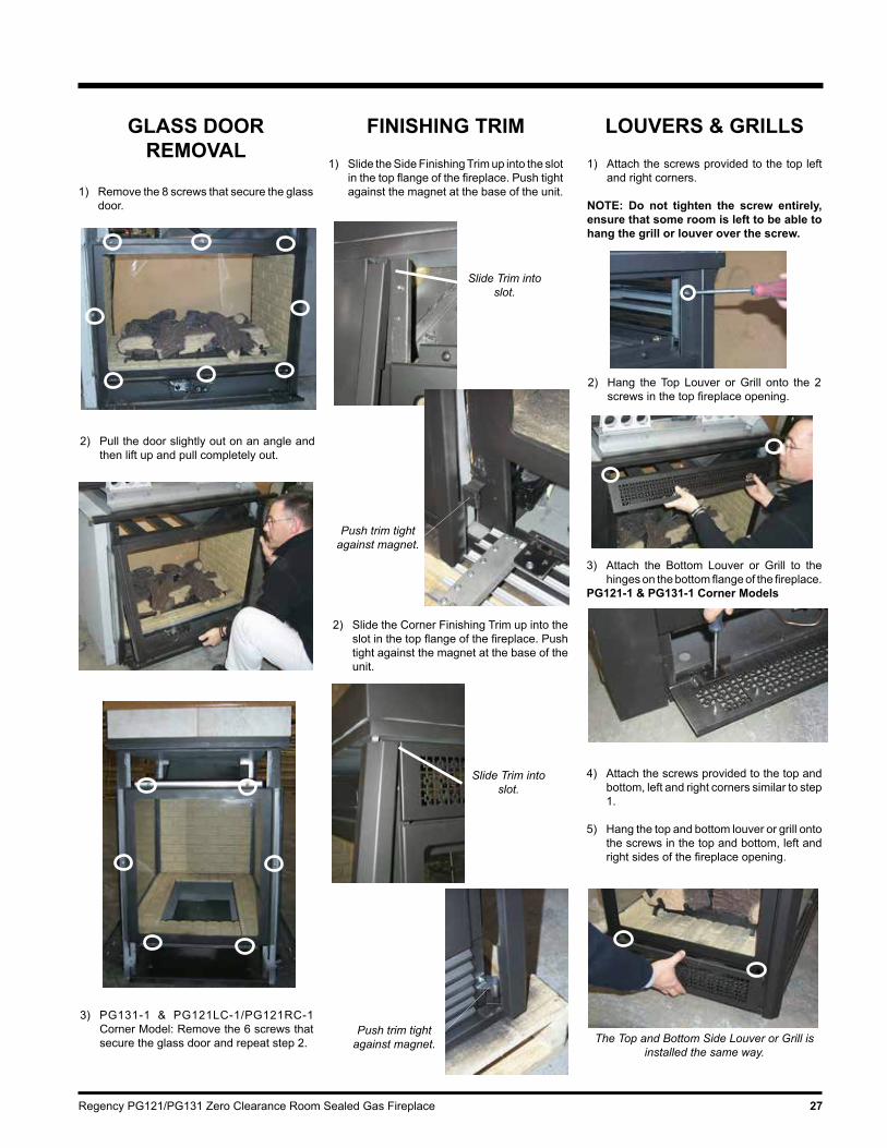
GLASS DOOR REMOVAL
1) Remove the 8 screws that secure the glass door.
2) Pull the door slightly out on an angle and then lift up and pull completely out.
3) PG131-1 & PG121LC-1/PG121RC-1 Corner Model: Remove the 6 screws that secure the glass door and repeat step 2.
FINISHING TRIM1) Slide the Side Finishing Trim up into the slot
in the top flange of the fireplace. Push tight against the magnet at the base of the unit.
LOUVERS & GRILLS1) Attach the screws provided to the top left
and right corners.
NOTE: Do not tighten the screw entirely, ensure that some room is left to be able to hang the grill or louver over the screw.
2) Hang the Top Louver or Grill onto the 2 screws in the top fireplace opening.
3) Attach the Bottom Louver or Grill to the hinges on the bottom flange of the fireplace.
PG121-1 & PG131-1 Corner Models
4) Attach the screws provided to the top and bottom, left and right corners similar to step 1.
5) Hang the top and bottom louver or grill onto the screws in the top and bottom, left and right sides of the fireplace opening.
The Top and Bottom Side Louver or Grill is installed the same way.
2) Slide the Corner Finishing Trim up into the slot in the top flange of the fireplace. Push tight against the magnet at the base of the unit.
Slide Trim into slot.
Push trim tight against magnet.
Slide Trim into slot.
Push trim tight against magnet.

Regency PG121/PG131 Zero Clearance Room Sealed Gas Fireplace28
WIRING DIAGRAM
INSTALLATION
REMOTE CONTROL Use the Regency Remote Control Kit approved for this unit. Use of other systems may void your warranty.
The remote control kit comes with a hand held transmitter and a wall mounting plate.
1) Choose a convenient location to mount the hand held transmitter, protection from extreme heat is very important.
The remote can also be used as a wall thermostat.
CAUTION: Label all wires prior to disconnection when servic-ing controls. Wiring errors can cause improper and dangerous operation.
This heater requires a 240V A.C. supply for the gas control to operate. A 240V A.C. power supply is needed for the fan/blower operation.
Caution: Ensure that the wires do not touch any hot surfaces and are away from sharp edges.
FLAME SENSORSPARK IGNITOR
PILOT
BROWN (ACTIVE)
BLUE (NEUTRAL)
VIOLET
BLUE
BROWN
WHITE
RED
BLACK
FA
N
FAN HiCom
Lo
Hi
Lo
Com
TERMINALBLOCK
BLACK
RED
WHITE
SIT 201 IGNITION CONTROL MODULE
JUMPER
2 1
ORANGE
ORANGE
MODULE - SPARK
BLACK
12 11 910 8 7 6 5 4 3 2
RESET SWITCH (NC)
YELLOW
VIOLET
YELLOW
BLACK
1
SIGMA 845 VALVE
RED
BLUEGREEN
BROWN
3
54
21
SIT
MODULATING
(MD)COIL
ORANGE
ORANGE
RED
REDMODULE - FLAME
MODULE - GROUND
GREEN
MED FAN
NEUTRAL
NEUTRAL
COMMAND BOX
ACTIVE
LOW
THERM
HIGH
TH2
TH1
MOD1
MOD2
GND
GND
GND

Regency PG121/PG131 Zero Clearance Room Sealed Gas Fireplace 29
OPERATING INSTRUCTIONS
OPERATING INSTRUCTIONS
Before operating this appliance, proceed through the following check list.
1) Read and understand these Instructions before operating this appliance.
2) Check to see that all wiring is correct and enclosed to prevent possible shock.
3) Check to ensure there are no gas leaks.
4) Make sure the three pieces of door glass are properly positioned. Never operate the appliance with any of the glass removed or with the door open.
5) Verify that all flueing and the cap is unob-structed.
6) Verify log placement.
LIGHTING INSTRUCTIONS
1) Plug the power cord into a power outlet.
2) Press and release the ON/OFF button once to start the unit.
3) After approximately 3 seconds the spark ignition system will spark for 40 seconds to light the main burner.
4) If the main burner does not light, reset the unit.
ADJUSTING FLAME HEIGHT
There are six flame settings that can be adjusted by pressing and releasing the plus (+) and minus (-) FLAME button.
The FLAME setting button is located on the control panel in behind the pedestal door.
FAN OPERATIONSet the fan speed on the control panel located in behind the bottom louvre.
Pressing and releasing the plus (+) FAN button will change the fan speed as follows:
OFF -> LOW -> MEDIUM -> HIGH -> OFF, etc.
Pressing and releasing the minus (-) FAN button will be the reverse of the above.
RESETTINGTHE UNIT
1) Open the bottom louvre of the unit.
2) Press and release the reset button, located on the unit's control panel once.
3) Wait for approximately 3 seconds and the pilot sparks can be heard and seen. It would take 2 to 3 seconds for the flame to be lit.
NOTE: A period of 30 seconds must pass before another reset is attempted.
SHUTDOWNINSTRUCTIONS
1) Press the ON/OFF button once.
2) Turn off all electric power to the appliance if service is to be performed.
Regency PG121/PG131 Zero Clearance Room Sealed Gas Fireplace30
OPERATING INSTRUCTIONS
FIRST FIREDO NOT BURN THE APPLIANCE WITH-OUT THE GLASS FRONT IN PLACE.
The first fire in your stove is part of the paint cur-ing process. To ensure that the paint is properly cured, it is recommended that you burn your fireplace for at least four (4) hours the first time before you use it with the fan on.
When first operated, the unit will release an odour caused by the curing of the paint, the burning off of any oils remaining from manufacturing. Smoke detectors in the house may go off at this time. Open a few windows to ventilate the room for a couple of hours.
Note: When the glass is cold and the appli-ance is lit, it may cause condensation and fog the glass. This condensation is normal and will disappear in a few minutes as the glass heats up.
During the first few fires, a white film may develop on the glass front as part of the curing process. The glass should be cleaned after the unit has cooled down or the film will bake on and become very difficult to remove. Use a non-abrasive cleaner and DO NOT ATTEMPT TO CLEAN THE GLASS WHILE IT IS HOT.
NORMAL OPERATING SOUNDS OF GAS
APPLIANCESIt is possible that you will hear some sounds from your gas appliance. This is perfectly normal due to the fact that there are various gauges and types of steel used within your appliance. Listed below are some examples. All are normal operating sounds and should not be considered as defects in your appliance.
Blower:Regency gas appliances use high tech blowers to push heated air farther into the room. It is not unusual for the fan to make a "whirring" sound when ON. This sound will increase or decrease in volume depending on the speed setting of your fan speed control.
Burner Tray: The burner tray is positioned directly under the burner tube(s) and logs and is made of a differ-ent gauge material from the rest of the firebox and body. Therefore, the varying thicknesses of steel will expand and contract at slightly different rates which can cause "ticking" and "cracking" sounds. You should also be aware that as there are temperature changes within the unit these sounds will likely re-occur. Again, this is normal for steel fireboxes.
Gas Control Valve: As the gas control valve turns ON and OFF, a dull clicking sound may be audible, this is normal operation of a gas regulator or valve.
Unit Body/Firebox: Different types and thicknesses of steel will expand and contract at different rates resulting in some "cracking" and "ticking" sounds will be heard throughout the cycling process.
AERATION ADJUSTMENT
The burner aeration is factory set. Adjustment may be needed due to the local gas supply or altitude. As a general rule if the flame is too yel-low open up the air shutter, if it is too blue close the air shutter.
NG 10mm openLPG 10mm open NOTE:This adjustment is only to be made by an authorised person.
Carbon deposits are a possibility on appli-ances incorporating live fuel effect flames.

Regency PG121/PG131 Zero Clearance Room Sealed Gas Fireplace 31
MAINTENANCE INSTRUCTIONS
Any maintenance required accessing the glass door of the unit must be performed by an authorized service person.
1) Always unplug the power cord before cleaning. For relighting, refer to lighting instructions. Keep the burner and control compartment clean by brushing and vacu-uming at least once a year. When cleaning the logs, use a soft clean brush as the logs are fragile and easily damaged.
2) Clean glass (never when unit is hot), appli-ance, louvres, and door with a damp cloth. Never use an abrasive cleaner. The gold louvres (and optional gold door) may be scratched if abrasives are used to clean them.
The heater is finished in a heat resistant paint and should only be refinished with heat resistant paint (not with wall paint). Regency uses StoveBright Paint - Metallic Black #6309.
3) Make a periodic check of burner for proper position and condition. Visually check the flame of the burner periodically, making sure the flames are steady; not lifting or floating. If there is a problem, call an authorized service person.
4) The appliance and flueing system must be inspected before use, and at least annu-ally, by an authorized field service person, to ensure that the flow of combustion and ventilation air is not obstructed.
During the annual service call, the burners should be removed from the burner tray and cleaned. Replace the embers - do not block the pilot or burner ports.
5) Keep the area near the appliance clear and free from combustible materials, gasoline and other flammable vapours and liquids.
General Flue Maintenance
Conduct an inspection of the flueing system semi-annually. Recommended areas to inspect as follows:
1) Check the Flueing System for corrosion in areas that are exposed to the elements. These will appear as rust spots or streaks, and in extreme cases, holes. These com-ponents should be replaced immediately.
2) Remove the Cap, and shine a flashlight down the Flue. Remove any bird nests, or other foreign material.
COPY OF THE LIGHTING PLATE INSTRUCTIONS
OPERATING INSTRUCTIONS
Part #: 918-332a (for ECS units, except for FG38)
Colours: Black on Grey, except for parts indicated as being Red.Size: 100%
Feb. 8/06: Changed AG 601 to AS5601-2004 as per Paul Watters.

Regency PG121/PG131 Zero Clearance Room Sealed Gas Fireplace32
MAINTENANCE
3) Check for evidences of excessive condensa-tion, such as water droplets forming in the inner liner, and subsequently dripping out the joints, Continuous condensation can cause corrosion of caps, pipe, and fittings. It may be caused by having excessive lateral runs, too many elbows, and exterior portions of the system being exposed to cold weather.
4) Inspect joints, to verify that no pipe sections or fittings have been disturbed, and conse-quently loosened. Also check mechanical supports such as Wall Straps, or plumbers' tape for rigidity.
LOG REPLACEMENTThe unit should never be used with broken logs. Turn off the gas valve and allow the unit to cool before opening door and carefully remove the logs. (The pilot light generates enough heat to burn someone.) If for any reason a log should need replacement, you must use the proper replacement log. The position of these logs must be as shown in the diagrams under Log Installation.
Note: Improper positioning of logs may cre-ate carbon build-up and will severely alter the unit's performance which is not covered under warranty.
GLASS GASKET If the glass gasket requires replacement use a tadpole glass gasket (Part # 936-155).
DOOR GLASSYour Regency fireplace is supplied with high temperature 5mm-Tempered glass & 5mm-Ceramic glass. If your glass requires cleaning, we recommend using an approved glass cleaner available at all authorized dealers. Do not use abrasive materials.
CAUTION & WARNINGS:
* Do not clean when the glass is hot.* The use of substitute glass will void all prod uct warranties.* Care must be taken to avoid breakage of the glass.* Do not strike or abuse the glass.* Do not operate this fireplace without the glass front or with a cracked or broken glass front.* Wear gloves when removing damaged or broken glass.* Replacement of the glass panels should be done by a licensed or authorized service per son.
GLASS REPLACEMENT
In the event that you break your glass by impact, purchase your replacement from an authorized Regency dealer only. Replacement glass is shipped already installed into the door frame.
REPLACEMENT PARTS:
Front Door - Tempered (Part# 360-528/P)Side Door - Tempered (Part# 360-529/P)Front Door - Ceramic (Part# 360-946)Side Door - Ceramic (Part# 360-948)
GOLD-PLATED ACCESSORIES
The 24 carat gold-plated finish requires little maintenance, and need only be cleaned with a damp cloth. DO NOT use abrasive materials or chemical cleaners, as they may harm the finish and void the warranty. Clean any fingerprints off before turning the unit on.
VALVE TRAYREPLACEMENT
1) Shut off the gas supply.
2) Remove the louvers and trim kit. Remove the front door.
3) Remove the logs, embers.
4) Remove the grate by lifting straight up.
5) Remove the side brick clip in the top of the firebox and then slide the Side Brick Panel out. The brick panels are very fragile - handle with care.

Regency PG121/PG131 Zero Clearance Room Sealed Gas Fireplace 33
8) Remove the Side Base Brick Panels and finally the Long Base Brick Panels.
MAINTENANCE
Remove Left & Right Side Base Brick Panels
Remove the 2 Long Base Brick Panels
9) Open the bottom louvre and remove the 2 screws which secure the front cover to the valve tray.
7) Slide the burner assembly away from the orifice and lift out.
6) Remove the burner by removing the 4 screws.
10) Unplug the 5 pin Molex Connector and carefully pull out the control box.
5 Pin Molex Connector
11) Disconnect the inlet gas line.
12) Unplug the 2 orange wires from the Gas Pressure Electronic Modulator.
13) Unplug the 5 pin Molex Connector from the valve.
14) Unplug the igniter and the flame cables from the module.
Igniter and Flame Cables
15) Remove the 16 screws that secure the valve tray.
16) Lift the entire assembly out.
17) To replace the burner tray assmebly, reverse these instructions.
18) Check for any gas leaks.
19) Check for proper flame appearance and glow on logs.
5 Pin Molex Con-nector from the
Valve.

Regency PG121/PG131 Zero Clearance Room Sealed Gas Fireplace34
MANUAL CONTROL REPLACEMENT
1) Unplug the power source.
2) Open the bottom louver.
5) Remove the valve heat shield by undoing the 2 screws.
Valve Heat Shield
6) Pull out the ECS box by carefully lifting it up off the velcro.
7) Remove the ECS box cover by undoing the 3 screws.
8) Unplug in the CAT5 cable of the manual control box from the con-nector in the ECS box.
Manual Control BoxLouver Bracket
ECS Box
3) Undo the 3 screws to remove the manual control box from the louver.
4) Remove the louver bracket from the manual control box by undoing one screw.
9) Plug the replacement manual control switch CAT5 cable into the connector in the ECS box.
10) Re-install the cover on the ECS box. Ensure to fit the rest of the cable into the groove in the ECS box.
11) Put the ECS box back in place under the firebox.
12) Reverse steps 5 to 1.
MAINTENANCE

Regency PG121/PG131 Zero Clearance Room Sealed Gas Fireplace 35
PARTS LIST
ELECTRONIC COMPONENTS PARTS LISTNote: Depending on the model, the diagram below may not be exactly as shown - for reference purposes only.
910-936910-082
910-088
910-089
910-084
910-526910-080
910-521, 910-522, 910-523
910-912
910-906 910-083911-121
910-514
FG38 FG39 PG33 PG36 / PG36D
PG121/PG131
IG35 IG34 GF900L/C
910-909 Fan Resistor 910-936 Intermittent Pilot N/A N/A 910-082 Direct Spark Ignitor N/A N/A N/A N/A N/A N/A
910-089 Flame Cable N/A N/A N/A N/A N/A N/A
910-088 Spark Cable N/A N/A N/A N/A N/A N/A
910-084 Control Box N/A
910-527 Manual Control Switch N/A N/A N/A N/A N/A
910-080 Valve 910-521 Control Box Cable (1)910-522 Control Box Cable (2)910-523 Control Box Cable (3)910-525 Control Box Cable (4)
*N/A (2) (1)(1)
(3)N/A* (2) N/A
910-912 Ignition Module to Valve Cable
N/A N/A
911-161 Reset Switch N/A N/A 910-083 Ignition Module (1)911-121 Ignition Module (2)
(1)(2) (2) (2) (2) (2)
(1)(2) (2)
910-514 Jumper Wire N/A 910-527 Manual Control Switch N/A N/A N/A N/A N/A
910-935 Manual Control Switch N/A N/A N/A
**Note: The Control Box Cable wires for the FG38 come separately: 910-502, 910-505, 910-506, 910-507, 910-509

Regency PG121/PG131 Zero Clearance Room Sealed Gas Fireplace36
PARTS LIST
PG121-1 (SEE THRU) MAIN ASSEMBLY
Part # Description Part # Description Part # Description
1) 360-528/P Door Assy Front - Tempered 360-946 Door Assy Front - Ceramic (Optional)
9) 360-046 Nailing Strip - Top - Front10) 360-047 Nailing Strip - Top - Side11) 430-001 Standoff - Top17) 360-086 Gasket - Relief Door24) * Relief Door Assembly
32) 362-528 Brick Panel - Base - Front33) 362-528 Brick Panel - Base - Side34) 902-603 Brick Panel - Side
135) 360-069 Heat Shield - Side
146) 360-035 Finishing Trim150) 360-123 Magnet Bracket - Front151) 904-258 Magnet
168) 360-068 Door Cover Assembly - Side
171) 360-920 Louver Front - Black (set) 360-922 Louver Front - Black/Gold (set) 360-924 Louver Front - Black/Steel (set) 360-926 Louver Front - Black/Brass (set)
181) * Extension Trim - See Thru
204) 360-940 Dec. Grill Front - Black (set)
205) 948-216 Regency Logo Plate 206) 910-172 Fan Axial 240V
918-648 Manual
*Not available as a replacement part.

Regency PG121/PG131 Zero Clearance Room Sealed Gas Fireplace 37
PARTS LIST
PG131-1 (PIER) MAIN ASSEMBLY
Part # Description Part # Description Part # Description
1) 360-528/P Door Assy Front - Tempered 360-946 Door Assy Front - Ceramic (Optional)
2) 360-529/P Door Assy Side - Tempered 360-948 Door Assy Side- Ceramic (Optional)
9) 360-046 Nailing Strip - Top - Front10) 360-047 Nailing Strip - Top - Side11) 430-001 Standoff - Top
17) 360-086 Gasket - Relief Door24) * Relief Door Assembly
32) 362-528 Brick Panel - Base - Side33) 362-528 Brick Panel - Base - Front34) 902-603 Brick Panel - Side141) 360-031 Column Finishing Trim
146) 360-035 Finishing Trim
149) 360-122 Magnet Bracket - Corner150) 360-123 Magnet Bracket - Front151) 904-258 Magnet
171) 360-920 Louver Front - Black (set) 360-922 Louver Front - Black/Gold (set) 360-924 Louver Front - Black/Steel (set) 360-926 Louver Front - Black/Brass (set)
173) 360-932 Louver Side - Black (set) 360-934 Louver Side - Black/Gold (set) 360-936 Louver Side - Black/Steel (set) 360-938 Louver Side - Black/Brass (set)
181) * Extension Trim - Pier
204) 360-940 Dec. Grill Front - Black (set)206) 910-172 Fan Axial 240V224) 360-942 Dec. Grill Side - Black (set)
225) 948-216 Regency Logo Plate
918-648 Manual
*Not available as a replacement part.

Regency PG121/PG131 Zero Clearance Room Sealed Gas Fireplace38
PG121RC-1 (RIGHT CORNER) MAIN ASSEMBLY
Part # Description Part # Description Part # Description
PARTS LIST
1) 360-528/P Door Assy Front - Tempered 360-946 Door Assy Front - Ceramic (Optional)
2) 360-529/P Door Assy Side - Tempered 360-948 Door Assy Side - Ceramic (Optional)
9) 360-046 Nailing Strip - Top - Front10) 360-047 Nailing Strip - Top - Side11) 430-001 Standoff - Top 780-013 Standoff - Rear17) 360-086 Gasket - Relief Door24) * Relief Door Assembly
32) 362-528 Brick Panel - Base - Side33) 362-528 Brick Panel - Base - Front34) 902-603 Brick Panel - Side35) 902-604 Brick Panel - Front
138) 360-063 Heat Shield - Front141) 360-031 Column Finishing Trim
146) 360-035 Finishing Trim - Left Side
149) 360-122 Magnet Bracket - Corner150) 360-123 Magnet Bracket - Front151) 904-258 Magnet158) 360-060 Door Cover Assembly-Front
171) 360-920 Louver Front - Black (set) 360-922 Louver Front - Black/Gold (set) 360-924 Louver Front - Black/Steel (set) 360-926 Louver Front - Black/Brass (set) 173) 360-932 Louver Side - Black (set) 360-934 Louver Side - Black/Gold (set) 360-936 Louver Side - Black/Steel (set) 360-938 Louver Side - Black/Brass (set)
181) * Extension Trim
204) 360-940 Dec. Grill Front - Black (set)206) 910-172 Fan Axial 240V224) 360-942 Dec. Grill Side - Black (set)
225) 948-216 Regency Logo Plate
918-648 Manual
*Not available as a replacement part.

Regency PG121/PG131 Zero Clearance Room Sealed Gas Fireplace 39
PARTS LIST
PG121LC-1 (LEFT CORNER) MAIN ASSEMBLY
Part # Description Part # Description Part # Description
1) 360-528/P Door Assy Front - Tempered 360-946 Door Assy Front - Ceramic (Optional)
2) 360-529/P Door Assy Side - Tempered 360-948 Door Assy Side - Ceramic (Optional)
9) 360-046 Nailing Strip - Top - Front10) 360-047 Nailing Strip - Top - Side11) 430-001 Standoff - Top
17) 360-086 Gasket - Relief Door24) * Relief Door Assembly
32) 362-528 Brick Panel - Base - Side33) 362-528 Brick Panel - Base - Front34) 902-603 Brick Panel - Side35) 902-604 Brick Panel - Front
138) 360-069 Heat Shield - Front
141) 360-031 Column Finishing Trim146) 360-035 Finishing Trim
149) 360-122 Magnet Bracket - Corner150) 360-123 Magnet Bracket - Front151) 904-258 Magnet
158) 360-062 Door Cover Assembly-Front
171) 360-920 Louver Front - Black (set) 360-922 Louver Front - Black/Gold (set) 360-924 Louver Front - Black/Steel (set) 360-926 Louver Front - Black/Brass (set)173) 360-932 Louver Side - Black (set) 360-934 Louver Side - Black/Gold (set) 360-936 Louver Side - Black/Steel (set) 360-938 Louver Side - Black/Brass (set)
204) 360-940 Dec. Grill Front - Black (set)206) 910-172 Fan Axial 240V224) 360-942 Dec. Grill Side - Black (set)
225) 948-216 Regency Logo Plate
918-648 Manual
*Not available as a replacement part.

Regency PG121/PG131 Zero Clearance Room Sealed Gas Fireplace40
BURNER ASSEMBLY & LOG SET
Part # Description 360-930 Log Set41) Front Right Log42) Front Left Log43) Middle Left Log44) Middle Right Log
360-578/P Valve Assembly -NG 360-580/P Valve Assembly - LP56) 910-080 Valve SIT - NG 910-081 Valve SIT - LP
57) 360-090 Gasket - Valve Tray58) * Valve Tray 66) 910-936 Pilot Assembly - NG 910-937 Pilot Assembly - LPG 67) * Pilot Holder68) W840470 Pilot Assembly Gasket
79) 360-525 Burner Assembly82) 360-027 Grate Assembly 904-690 Orifice #31 - NG 936-170 Orifice Gasket *Not available as a replacement part.
PARTS LIST

Regency PG121/PG131 Zero Clearance Room Sealed Gas Fireplace 41
NOTES
___________________________________________________
___________________________________________________
___________________________________________________
___________________________________________________
___________________________________________________
___________________________________________________
___________________________________________________
___________________________________________________
___________________________________________________
___________________________________________________
___________________________________________________
___________________________________________________

Regency PG121/PG131 Zero Clearance Room Sealed Gas Fireplace42
WARRANTY
Regency® Fireplace Products are designed with reliability and simplicity in mind. In addition, our internal Quality Assurance Team carefully inspects each unit thoroughly before it leaves our door. Regency® is pleased to extend this limited lifetime warranty to the original purchaser of a Regency® Product. Regency® will repair or replace goods free of charge in the event of defects arising from faulty materials or workmanship in accordance with the warranty terms in relation to Definitions, Warranty Conditions and Exclusions stated in this document.
The benefits to the consumer given by this warranty are in addition to all other rights and remedies of the consumer under a law in relation to the goods or services to which the warranty relates.
Our goods come with the guarantees that cannot be excluded under the Australian Consumer Law. You are entitled to a replacement or refund for a major failure and for compensation for any other foreseeable loss or damage. You are also entitled to have the goods repaired or replaced if the goods fail to be of acceptable quality and the failure does not amount to a major failure.
The Warranty: LifetimeCovered under the agreement are the following components: The combustion chamber, heat exchanger, burner tubes/pans, logs, glass crystals, ceramic spa stones, pebbles, brick panels and gold plating (against defective manufacture only) are covered under the Limited Lifetime Warranty for five (5) years for parts and labour and parts only thereafter.
External casting, surrounds and grills are covered against cracks and warps resulting from manufacturer defects, parts and labour for one (1) year from the date of purchase and parts only thereafter.
Regency Fireplace Products is not liable for freight or labour on any gas appliance replaced in the field.
Special Finishes - One year on stainless steel panels, nickel overlays, nickel faceplates, brushed nickel and antique copper full screens and doors. You can expect some changes in color as the product "ages" with constant heating and cooling. FPI warranties the product for any manufacturing defects on the original product. However, the manufacturers warranty does not cover changing colors and marks, ie. finger prints, etc applied after the purchase of the product. Damage from the use of abrasive cleaners is not covered by warranty.
Electrical components such as fans, switches, ignition modules, wiring, thermodiscs, remote control, thermopiles, thermocouples and gas valves are covered for one year for parts and labour from the date of purchase.
The warranty on brass parts is for one year, no labour. The brass is not warranted against tarnishing.
Repair/replacement parts purchased by the consumer from Regency® after the original coverage has expired on the unit will carry a 90 day warranty valid with a receipt only. Any item shown to be defective will be repaired or replaced at our discretion. No labour coverage is included with these parts.
Conditions:All installations must be performed by a qualified gas fitter and installed according to all applicable local and national codes. Also, all service work must be carried out by a qualified gas service person provided by the selling dealer. It is the responsibility of the installer to ensure that the appliance is firing as per rating plate. Any part or parts of this unit which in our judgement show evidence of such defect will be repaired or replaced at Regency®'s option, through an accredited distributor or agent provided that the defective part be returned to the distributor or agent Transportation Prepaid, if requested. In areas where there is not an approved service agent or the closest approved service agent is situated more than thirty (30) kilometres from the installation, Regency is not obliged to arrange warranty repairs and travel and/or additional labour charges will apply.
Porcelain/Enamel - Absolute perfection is neither guaranteed nor commercially possible. Any chips must be reported and inspected by an authorised dealer within three days of installation. Reported damage after this time will be subject to rejection.
It is the general practice of Regency® to charge for larger, higher priced replacement parts and issue credit once the replaced component has been returned to Regency and evaluated fro manufacturer defect.
At all time Regency reserves the right to inspect product in the field which is claimed to be defective.
All claims must be submitted to Regency® by authorised selling dealers. It is essential that all submitted claims provide all of the necessary information including customer name, purchase date, serial #, type of unit, problem, and part or parts requested, without this information the warranty will be invalid.
Exclusions:This limited Lifetime Warranty does not extend to or include paint, door or glass gasket or trim. It does not cover installation and operational related problems such as over-firing, down drafts or spillage caused by environmental conditions, nearby trees, buildings, hilltops, mountains, inadequate flueing or ventilation, excessive offsets, negative air pressures caused by insufficient make up air, mechanical systems such as furnaces, fans, clothes dryers etc.
Embers, rockwool, gaskets, door handles and paint are not covered under the terms of this warranty policy.
Regency® will not be liable for acts of God, or acts of terrorism, which cause malfunction of the appliance.
Performance problems due to operator error will not be covered by this warranty policy.
The warranty does not extend to any part or parts which show evidence of misuse or abuse, neglect, accident, lack of maintenance, or improper installation.
Products made by other manufacturers and used in conjunction with the operation of this appliance without authorisation from Regency®, may nullify your warranty on this product.
Regency shall in no event be liable for any special, indirect consequential damages of any nature whatsoever which are in excess of the original purchase price of the product. Any alteration to the unit which causes sooting or carboning that results in damage to the exterior facia is not the responsibility of Regency Fireplace Products.
SUBJECT TO CHANGE.

Regency PG121/PG131 Zero Clearance Room Sealed Gas Fireplace 43
WARRANTY
DISTRIBUTORS: Western Australia Eastern Australia
Air Group Australia Fireplace Products Australia PTY. Ltd.
28-30 Division St. 1-3 Conquest Way
Welshpool, WA 6106 Hallam, VIC 3803
08 9350 2200 03 9799 7277
NOTE: PLEASE RETAIN YOUR INVOICE AS PROOF OF PURCHASE FOR WARRANTY VERIFICATION
INCORRECT INSTALLATION OR GAS PRESSURE SETTINGS ARE NOT COVERED BY WARRANTY
A SERVICE OR CALLOUT FEE WILL BE CHARGED IN THESE CIRCUMSTANCES.

Printed in Canada© Copyright 2015, FPI Fireplace Products International Ltd. All rights reserved.
Installer:Pleasecompletethefollowinginformation
Dealer Name & Address: ______________________________________________
___________________________________________________________________
Installer: ___________________________________________________________
Phone #: ___________________________________________________________
Date Installed: ______________________________________________________
Serial No.: __________________________________________________________
Register your Regency® warranty onlinewww.regency-fire.com.au
Reasons to register your product online today!
• View and modify a list of all your registered products.• Request automatic email notification of new product updates.• Stay informed about the current promotions, events, and special
offers on related products.• Help assure you get the most out of your warranty.• Eliminate confusion and frustration if warranty** service is required in
the future. ** Proof of purchase required at time of warranty request.