Embed Size (px)
Citation preview

INSTALLATION & OPERATING
INSTRUCTION MANUAL
ownersmanual
MODEL NOS.4007332400773255073326257732
FOR USE WITHNATURAL GAS ONLY
MODEL NOS.4007331400773155073316257731
FOR USE WITHLIQUEFIED
PETROLEUM (L.P.)GAS ONLY
Save This Manual ForFuture Reference.
COUNTERFLOW DIRECT VENTGAS WALL FURNACES
READ THIS OWNERS MANUALCAREFULLY BEFORE YOU INSTALL
YOUR NEW WILLIAMS WALL FURNACE
WARNING: If the information in this
manual is not followed exactly, a fire or ex-plosion may result causing propertydamage, personal injury or loss of life.
-- Do not store or use gasoline or otherflammable vapors and liquids in thevicinity of this or any other appliance.
WHAT TO DO IF YOU SMELL GAS
• Open all windows.• Do not try to light any appliance.• Do not touch any electrical switch; do
not use any phone in your building.• Extinguish any open flame.• Immediately call your gas supplier
from a neighbor's phone. Follow thegas supplier's instructions.
• If you cannot reach your gas supplier,call the fire department.
Installation and service must be per-formed by a qualified installer, serviceagency or the gas supplier.
WARNING: Improper installation, adjust-ment, alteration, service or maintenancecan cause injury or property damage.Refer to this manual. For assistance or
additional information consult a qualifiedinstaller, service agency or the gassupplier.
WARNING: This direct vent furnace is approved for aftermarket mobile home installations (once themobile home is sold, installed and stationary) unless prohibited by local codes. Not for mobile homemanufacturer (factory) installation. Do not install any of these furnaces (natural or L.P. Gas) in trailersor recreational vehicles.
Williams Furnace Co., 225 Acacia St., Colton, CA 92324, USAPRINTED IN U.S.A. 12/98 P321004
Contents
Your Williams Warranty ......................... 2Introduction .................................. 3Basic Description .............................. 3Optional Accessories ........................... 3Helpful Installation Information ................... 3Safety Rules ................................. 4Unpack Your Furnace .......................... 5Basic Tools Needed ............................ 5Basic Materials ............................... 5Installing Your Wall Furnace ..................... 6Locating Wall Furnace and Thermostat .......... 6-7
Recessed Mount Installation ................. 7-9Surface Mount installation .................. 9-10Thermostat Installation ..................... 11-12
Vent Installation .......................... 12-13Mounting Your Furnace ..................... 14-15Gas Supply and Piping ...................... 15-16Electrical Wiring ............................. 17Start Up Procedure ........................... 18Operating Your Furnace ..................... 19-24How To Care For Your Furnace ............... 25-26Furnace Technical Information .................. 26Wiring Diagrams ........................... 27-28TROUBLESHOOTING CHART ............... 29-34Repair Parts .............................. 35-44SERVICE HINTS ...................... Back CoverHow To Order Repair Parts ............. Back Cover
Your WarrantyThe Manufacturer, Wilflams Furnace Co, warrants this wa_l furnace or heater to the original purchaser under the following conditions:
LIMITED ONE-YEAR WARRANTY
1 Any part thereof which proves to be defective in material or workmanship within one year from date of original purchase for use will be repaired or replaced at theManufacturer's option. FOB its factory.
2 No liability is assumed by the Manufacturer for remova_ or installation labor costs, nor for freight or delivery charges.
LIMITED EXTENDED WARRANTY
1. In addition to the above limited one*year warranty on the complete unit. any heat exchanger which burns out or rusts under normal installation, use and service
conditions during a period of nine years following expiration of the one-year warranty period will be exchanged for a like or functionally similar part, FOB Manufac-turer's factory
2 NO liability is assumed by the Manufacturer for removal or installation labor costs, nor for freight or delivery charges
LIMITATIONS
1. THIS LIMITED WARRANTY IS THE ONLY WARRANTY MADE BY THE MANUFACTURER IMPLIED WARRANTIES OF MERCHANTABILITY OR FITNESS FOR
ANY PARTICULAR PURPOSE ARE LIMITED TO THE SAME ONE YEAR TERM AS THIS EXPRESS WARRANTY UNDER NO CIRCUMSTANCES SHALL THEMANUFACTURER BE LIABLE FOR INCIDENTAL, CONSEQUENTIAL SPECIAL OR CONTINGENT DAMAGES OR EXPENSES ARISING DIRECTLY OR INDIRECT-
LY FROM ANY DEFECT IN THE PRODUCT OR ANY COMPONENT OR FROM THE USE THEREOE THE REMEDIES SET FORTH HEREIN ARE THE EXCLUSIVEREMEDIES AVAILABLE TO THE USER AND ARE IN LIEU OF ALL OTHER REMEDIES
Some states do not allow limitations on how long an implied warranty lasts, and some states do not allow the exclusion or fimitation of incidental
or consequential damages, so the above limitations or exclusions may not apply to you
2. This warranty does not include any charge for labor or installation
3. This warranty does not extend to painted surfaces nor to damage or defects resulting from accident, alteration, misuse or abuse, or improper installation
4 This warranty does not cover claims which do not involve defective workmanship or materials
DUTIES OF THE CONSUMER
1 The heating equipment must be installed by a qualified installer and operated in accordance with the installation and homeowner's instructions furnished with theequipment
2. Any travel, diagnostic costs, service labor, and labor to repair the defective unit will be the responsibility of the owner
3, A bill of sale, cancelled check, payment record or permit should be kept to verify purchase date to establish the warranty period.
4, Have the installer enter the requested information in the space below.
GENERAL
1. The Manufacturer neither assumes nor authorizes any person to assume for it any other obligation or liability in connection with said equipment.
2 Service under this warranty should be obtained by contacting your dealer. Provide the dealer with the model number, serial number and purchase date verification
3. If, within a reasonable time after contacting your dealer, satisfactory service has not been received, contact: Customer Service Department, 225 Acacia St., Colton,CA 92324, for assistance.
4. THIS WARRANTY GIVES YOU SPECIFIC LEGAL RIGHTS, AND YOU MAY ALSO HAVE OTHER RIGHTS WHICH VARY FROM STATE TO STATE.
INSTALLATION INFORMATION
Model No.
Orig. Purchaser_
Address
Serial No.
City and State_ Zip
Dealer
Address
City and State_ Zip
Installation date Signed by. _(Dealer orauthorized representative who certifies that this appliance has been installed in accordance with Manufacturer's instructions andlocal codes.)
--2 i

A Word From The ManufacturerDear Customer,
To set up our furnace assembly procedures, severe/hundred quality assurance, safety audit and design performancetests have been conducted according to the standards provided by the American Nationa/ Standards /nstitute, theDepartment of Energy and our certification agency -- the American Gas Association Laboratories.
This was done to assure you of receiving the best value and most re/iab/e appliance of its type available todayWe are confident that your Wi//iarns furnace can provide you years of low cost, efficient, heating comfort.Thank you for purchasing a Williams furnace.
Sincerely,Employees of Williams Furnace Company
Introduction
Please read our instructions before you install and use your furnace. This will help you obtain the full value from thisfurnace. It could help you avoid needless service costs, if the answer to the problem in found within this instructionmanual.
Basic DescriptionThe direct vent wall furnace is shipped ready to installagainst an exterior wall not exceeding 12" in thickness.Furnace may also be recessed up to 10" in a wall withstuds spaced 16" center-to-center.Always consult your local heating or plumbing inspector,building department or gas utility company regardingregulations, codes or ordinaces which apply to the installa-tion of a direct vent furnace.
Air is drawn in at the top by the fan and discharged througha grille near the floor. A two-speed fan is used with Models5507332, 6257732, 5507331, and 6257731. A single speedfan is used on all other models. The furnace contains amulti-slot burner (two on Models 5507332, 6257732,5507331, and 6257731) and burns either natural or L.R (li-quefied petroleum) gas, depending on the model you havepurchased.
The sealed combustion system draws combustion airdirectly from outdoors into the combustion chamber andcombustion gases are discharged directly to the outdoorsthrough tubes mounted to the rear of the furnace.The furnace heat exchanger is built of heavy gauge steeltreated for corrosion resistance. The fan at the top forcesair down along the front, back and sides of the heat ex-changer where it is discharged into the room. The furnacecabinet is also constructed of heavy gauge steel and hasa enamel paint finish.The furnace controls are located behind an access dooron the lower front of the furnace. All models are equippedwith American Gas Association listed gas valves and pilots.Models 4007332, 4007331, 5507332, and 5507331 areequipped with an electric ignition automatic pilot relightsystem.
Optional AccessoriesSide Outlet Grille Kit 6701
Lets you route some heated air to a second room. Mountson side wall of second room and must be within 10 inchesof wall furnace. See pages 7 & 10.Diffuser Grille Kit 6703 or 6704
Lets you route some heated air in a two-way direction. Kit6704 for one-way direction.
NOTE
Kits are identified on the carton by manufacturingnumber 6701, 6702, 6703 and 6704 are also listed onthe furnace rating plate.
Side Grille Kit 6702
Lets you route some heated air to side of furnace in thesame room. See pages 7 & 10.Trim Strip Kit 4701Provides finished edge at side of wall furnace. Neutralbeige enamel steel.Replacement Vent Cap Assembly 9801Should for any reason your vent cap becomes damagedand its operation impaired, replace it immediately.
Helpful Installation Information
The following booklets will help you in making the installation:ANSI/NFPA 70-1990 or current edition "National Electrical Code." In Canada: CSA C22.1 Canadian Electrical Code.American National Standard NFPA54/ANSI Z223.1 1988 or current edition "National Fuel Gas Code."
Obtain from -- American National Standards Institute, Inc., 1430 Broadway, New York, N.Y. 10018.In Canada: CAN/CGA B149 Installation Code.
--3--
Safety RulesWARNING
READ THESE RULES AND THE INSTRUCTIONSCAREFULLY. FAILURE TO FOLLOW THESERULES AND INSTRUCTIONS COULD CAUSE AMALFUNCTION OF THE FURNACE. THIS COULDRESULT IN DEATH, SERIOUS BODILY INJURY,AND/OR PROPERTY DAMAGE.
7.
umn. The maximum inlet gas supply pressure is 13"water column.
ANY SAFETY SCREEN, GUARD OR PARTS RE-MOVED FOR SERVICING AN APPLIANCE MUST BEREPLACED PRIOR TO OPERATING THE AP-PLIANCE TO AVOID PROPERTY DAMAGE, BODILYINJURY OR DEATH.
INSTALLATION MUST CONFORM TO LOCAL CODES. INTHE ABSENCE OF LOCAL CODES, INSTALLATIONMUST CONFORM WITH THE NATIONAL FUEL GASCODE, ANSI Z223.1. THE APPLIANCE, WHEN IN-STALLED, MUST BE ELECTRICALLY CONNECTED ANDGROUNDED IN ACCORDANCE WITH LOCAL CODESOR, IN THE ABSENCE OF LOCAL CODES, WITH THECURRENT NATIONAL ELECTRICAL CODE ANSI/NFPANO. 70.
IN CANADA
1. INSTALLATION MUST CONFORM TO LOCALCODES OR, IN THE ABSENCE OF LOCALCODES, THE CURRENT CAN/CGA B149 IN-STALLATION CODE.
2. THE APPLIANCE, WHEN INSTALLED, MUST BEELECTRICALLY CONNECTED AND GROUND-ED IN ACCORDANCE WITH LOCAL CODES OR,IN THE ABSENCE OF LOCAL CODES, WITHTHE CURRENT CSA C22.1 CANADIAN ELEC-TRICAL CODE.
3. REFERENCE IS MADE IN THIS MANUALREGARDING GAS TYPE AS LP. BE ADVISEDTHAT L.R IS NOT AVAILABLE IN CANADA,REFER TO PROPANEIL.P. GAS.
1. USE ONLY MANUFACTURER'S REPLACEMENTPARTS. USE OF ANY OTHER PARTS COULD CAUSEINJURY OR DEATH.
2. DO NOT install this furnace in an alcove.
3. DO NOT install these furnaces in a travel trailer,recreational vehicle or mobile home.
4. MAINTAIN all clearances specified in section"Locating Wall Furnace and Thermostat" and "VentInstallation."
5, BE SURE furnace is for type of gas to be used. Checkthe rating plate by the gas valve in the lower cabinet.Do not change it to use other gases. Unsafe opera-tion could result and could cause bodily injury anddeath.
6. For Natural gas, the minimum inlet gas supplypressure for the purpose of input adjustment is 5" col-umn. The maximum inlet gas supply pressure is 7"water column.For L.R gas, the minimum inlet gas supply pressurefor the purpose of input adjustment is 11" water col-
8.
9.
10.
11.
12.
13.
14.
15.
16.
17.
18.
19.
20.
INSTALL the furnace vent directly to the outdoors, us-ing the vent assembly supplied with the furnace, sothat harmful gases will not collect inside the building.
PROVIDE FOR ADEQUATE COMBUSTION AIR aroundvent cap on outside, see Fig. 2, pg. 6 and adequateair circulation around cabinet inside the open room.
NEVER vent flue gases into another room, a fireplaceor any space inside a building. This could cause pro-perty damage, bodily injury or death.
NEVER test for gas leaks with an open flame. Usesoap suds to check all gas connections. This will avoidthe possibility of fire or explosion.
ALLOW furnace to cool before servicing. Always shutoff electricity and gas to furnace when working on it.This will prevent any electrical shocks or burns.
DUE TO HIGH TEMPERATURES, locate the furnaceout of traffic and away from furniture and draperies.
ALERT children and adults to the hazards of high sur-face temperature and to keep away to avoid burns orclothing ignition.
CAREFULLY supervise young children when they arein the same room with the furnace.
DO NOT place clothing or other flammable materialon or near furnace.
INSTALLATION and REPAIR must be done by aqualified service person. The appliance should be in-spected before use and at least annually by a profes-sional service person. More frequent cleaning may berequired due to excessive lint from carpeting, beddingmaterial, etc. It is imperative that control compart-ments, burners and circulating air passages be keptclean.
BEFORE INSTALLING: To avoid electrical shock, turnoff electrical circuits that pass through the wall whereyou are going to install the furnace.
BE AWARE of good safety practices by wearing per-sonal protective equipment such as gloves and safe-ty glasses to avoid being injured by sharp metal edgesin or around furnace and while cutting or drilling holesin wood and or sheet metal.
CAUTION: Label all wires prior to disconnection whenservicing controls. Wiring errors can cause improperand dangerous operation. Verify proper operation afterservicing.
WARNING
DO NOT USE THIS HEATER IF ANY PART HAS BEEN UNDER WATER. IMMEDIATELY CALL A QUALIFIEDSERVICE TECHNICIAN TO INSPECT THE HEATER AND TO REPLACE ANY PART OF THE CONTROL SYSTEMAND ANY GAS CONTROL WHICH HAS BEEN UNDER WATER,
---4---
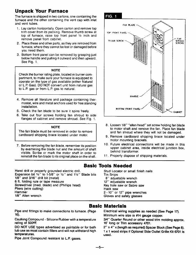
Unpack Your FurnaceThe furnace is shipped in two cartons, one containing thefurnace and the other containing the vent cap with inletand vent tubes.
1. Lay carton horizontally. Open carton and remove toptrim cover from its packing. Remove thumb screw attop of furnace, raise top front panel 1/2 inch andremove panel from cabinet.
2. Place these and other parts, as they are removed fromfurnace, where they cannot be lost or damaged beforeyou need them.
3. Bottom front panel can be removed by grasping justbelow handle and pulling it outward and then upward.See Fig. 1.
NOTE
Check the burner rating plate, located in burner com-partment, to make sure your furnace is equipped tooperate on the type of gas available (either Naturalor L.P. Gas). DO NOT convert unit from natural gasto L.P gas or from L.P gas to natural.
I
4. Remove all literature and package containing ther-mostat, wire and metal anchors used for free standinginstallation.
5. Check the fan blade to be sure it spins freely.
6. Take out four screws holding fan shroud to sideflanges of cabinet and remove shroud. See Fig. 1.
NOTE
The fan blade must be removed in order to remove
cardboard shipping brace located under motor.
7. Before removing the fan blade, remember its positionby examining the blade nut and the amount of shaftvisible. Scribe or mark the motor shaft in order toreinstall the fan blade to its original place on the shaft.
BoTmU FROHT PAHEL-
8. Loosen 1/8" "allen head" set screw holding fan bladeto motor shaft and remove the fan. Place fan bladeand fan shroud where they will not be damaged.
9. Remove cardboard shipping brace located undermotor mounting brackets.
10. Future electrical connections will be made in thisupper cabinet area, inside electrical junction box,behind transformer.
11. Properly dispose of shipping materials.
Basic Tools NeededHand drill or properly grounded electric drill.Expansion bit 1/2" to 1-5/8" or 1/2" and 11/2'' Blade bits1/8" and 3/16" drill bit (metal)6 ft. folding rule or tape measureScrewdriver (reed. blade) and (Phillips head)Pliers (wire cutting)Hammer1/8" Allen wrench
Stud Locator or small finish nailsTin Snips8" adjustable wrench
12" adjustable wrenchKey hole saw or Sabre sawHack saw2 - 10" or 12" pipe wrenchesGloves and safety glasses
Basic MaterialsPipe and fittings to make connections to furnace. (Page16).
Caulking Compound - Silicone Rubber with a temperaturerating of 500OF.DO NOT USE types advertised as paintable or for bathtub use as most contain fillers and will not withstand hightemperatures.
Electrical wiring supplies as needed (See Page 17).Minimum wire size is #14 gauge copper.3/4" Quarter Round or other wood trim molding approx.16' long or Trim accessory 4701.
2" x 4" x (length as required) Spacer Block (See Page 8).1 x 1 wood strips if Optional Side Outlet Grille Kit 6701 isused.
Pipe Joint Compound resistant to L.P. gases.
m5--

Installing Your Wall Furnace
The following steps are needed for proper installation andsafe operation of your furnace. If you have any doubts asto any requirements, check with local authorities for localand state codes affecting the installation
Obtain professional help where needed.
DO NOT install these furnaces in a travel trailer, recrea-tional vehicle or mobile home.
IMPORTANT
For satisfactory and trouble-free operation, be sure to:
1. Properly locate the furnace within the space to beheated.
2. Provide for adequate combustion air around vent capon outside, see Fig. 2 and adequate air circulationaround cabinet inside the open room.
3. Maintain minimum clearance: Floor 0" or ceiling 4",side wall 4". For exception to minimum side wallclearance, see Figs. 4, 5 & 6, pg. 7.
Locating Wall Furnace & Thermostat
Consider the following points before attempting to installthe furnace:
1. This is a direct vent wall furnace. It must be installedon an OUTSIDE WALL for proper venting of flue gases(Fig. 2).a. Wall furnace can be surface mounted on an outside
wall. (Surface Mount)b. Ideally, the wall should be the least windy side of the
dwelling, as strong gusts may extinguish the pilot.c. Furnace may be installed flush against a wall or
recessed up to 10" maximum. Wall thickness fromback surface of furnace to outside of wall can be 3/4"minimum to 12" maximum. See Fig. 3, pg. 7.
With standard furnace discharge outlet, do not installcloser than 4" to intersecting wall. See Fig. 4, pg. 7.
MINIMUM DIMENSIONS FROM VENT
d. If wall has a brick, block or other facing at least3/4-inch thick, the furnace can be mounted so it isrecessed into the waft between standard 2 x 4 wallstuds.
Studs must be spaced on 16 inch centers or stud spacewill have to be framed in. See pg. 7, Recessed Mounting.
2. The top of the furnace must be at least 4 inches fromthe ceiling.
3. Check the clearances needed from the furnace andvent (Fig. 2 and Fig. 4, pg. 7). You must place the fur-nace where you will have no less than the clearancesshown. See Fig. 5 & 6, Page 7.
4. When using optional kits 6703 or 6704, maintain theclearances as shown in Figs. 5 & 6, pg. 7.
5. When using optional kit 6701, maintain clearance asshown in Fig. 4, pg. 7. Use only optional outlet andgrille kits available from manufacturer.
6. The outside vent cap must be at least 18 inches awayfrom any window or other building opening (Fig. 2).
7. The furnace will not work if anything stops free entryof fresh air into the vent, or free flow of flue gases fromit. Be sure the center of the vent cap is at least 18inches above ground level or shrubs are as shown inFig. 2, pg. 6. Make sure shrubs are kept trimmed. Itmust also be at least 18 inches from any overhang,wall, or other blockage.
8. Try to place the furnace near the center of the spaceto be heated for good air circulation. Do not put itbehind a door or draperies. Do not put in a closet,alcove, hallway or other confined space.
9. Be sure that gas piping and electrical wiring can bebrought to the furnace. See sections on gas piping andelectrical wiring for your type of furnace mounting.
10. The bottom of the furnace must rest directly on a woodor concrete floor. If floor is other than wood or con-crete, such as carpet or sheet vinylflooring, there mustbe a piece of wood or sheet metal under the furnacethat is at least the same size as the bottom of thefurnace.
WARNING
IF VINYL SIDING IS USED ON EXTERIOR WALL SURFACE, HEAT FROM VENT CAP COULD CAUSE DISTOR-TION/DISCOLORATION. SHIELD TO PROTECT SIDING. CHECK WITH MANUFACTURER FOR ADDITIONALOPTIONS.
m6--

Locating Wall Furnace & Thermostat (ton't)10. Be sure to provide adequate clearance and service
access. The front of the furnace must face the openroom.
11. Choose a location for the thermostat about 5 feetabove the floor on an inside wall. The thermostat wiresupplied with your furnace is 20 feet long, whichshould be enough to run up through the attic of asingle-story home, so the thermostat can be a max-imum of 16 feet from the furnace measure in a straightline, or about 8 feet from the furnace if the wire is rununder the floon If more length is required, see noteon page 11.The thermostat should be sensing averageroom temperature; avoid the following;HOT SPOTS:
Concealed pipesor ducts
FireplacesRegistersTV setsRadiosLampsDirect sunlightKitchen
COLD SPOTS:Concealed pipes
or ductsStairwells-draftsDoors-draftsUnheated rooms onother side of wall
DEAD SPOTS:Behind doorsCorners, and alcoves
12. After picking a location that meets the requirements,inspect the wall, floor and outside areas. Make surethere are no pipes, wiring, or anything else that wouldinterfere with furnace or vent or thermostat installa-tion. If required, move them or pick a new location.
r-- -- -- _ VENT CAP
12 M Ii _b
_i / I[_" OUTLET
°U:L oT 6,Ol--
¢ _ .-,,_ VENT CAP
12 MAX I = I
7/%\12" MIN WHEN OPTIONAL 6703
TWO-WAY FRONT DIFFUSING GRILLE IS USED
t'- -- -- _ VENT CAPJ1 I'_ 3/4" MIN ',i ':1 I
_10" MAX
[_-A I:x_RECESSEDINSTALLATION CLEARANCE NOTE "-'--1
rflon of the furnace that is recessed into a wall up to {I 10' maximum recess may have (0) zero inch clearance to II combustibles. (See Fig. 3). All other clearances for the I
[ unrecessed portion must be observed. J
6702
_ 18 MIN -_
_VENT CAP
OPTIONALOUTLET6702
Recessed Mount InstallationFIND THE STUDS
Use a stud Iocatoror small finishing nails. Repeatedly driveand remove a nail into the wall in the area of the stud untilyou find it. Then find one side. Leave the nail there. Driveanother nail just on the other side of the same stud.Inside edge of the other stud should be about 141/2inchesfrom the one found. Drive finishing nail on inside edge ofthis stud.
I NOTE
IF STUDS ARE NOT ON 16 INCH CENTERS, SEECLOSE OFF STUD SPACE, PAGE 8.
CUT WALL OPENING
1. Lay out the required opening to be cut in inside wall(Fig. 7, pg. 8). Mark center of the vent hole on wall.Using a window, door or wall corner for reference,measure to find where vent will be on outside wall.Check to be sure clearances (Fig. 2, Fig. 4, Fig. 5 andFig. 6) will be right.
2. Drill a 1/4inch hole through vent hole center to the out-side wall to mark vent location.
3. Make the required cutout in inside wall. (Fig. 7, pg. 8)
--7--
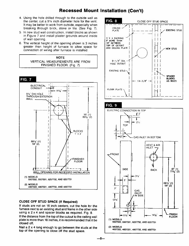
Recessed Mount Installation (Con't)
4. Using the hole drilled through to the outside wall asthe center, cut a 91/4 inch diameter hole for the vent.It may be better to work from outside, especially whenbreaking through brick, stone or tile. (See Fig. 7).
5. In new stud wall construction, install blocks as shownin Figure 7 and install plaster grounds around insideof wall opening.
6. The vertical height of the opening shown is 3 inchesgreater than height of furnace to allow space forconnection of wiring after furnace is installed.
NOTEVERTICAL MEASUREMENTS ARE FROM
FINISHED FLOOR. (Fig. 7)
i ,
ELECTRICALCONDUIT
91/4, DIA HOLE
THROUGH EXTERIORWALL
\
68vz° (1)59"(2i
90 (1)
80_.4,"(2)
BLOCKS1"x3"
FLOOR
r, .... _ q
WALL OPENING FOR RECESSED INSTALLATION
(1) MODELS5507332. 5507331, 6257732, AND 6257731
(2) MODELS4007332, 4007331, 4007732. AND 4007731
CLOSE OFF STUD SPACE (If Required)If studs are not on 16 inch centers, cut the hole for thefurnace next to an existingstudand frame in the other sideusing a 2 x 4 and spacer blocks as required. Fig. 8.If the distance from the top of the cutout to the ceiling wallplate is more than 18 inches, it is recommended that it beclosed off.
Nail a 2 x 4 long enough to go between the studs at thetop of the opening to close off the stud space.
CEJUNC --F}
PLATE 1
I/
2 × '_ BAC_KING J_l
IF _O_E ]HAN /
18" Bg-_t_EHTOP OF CUTOUTAND C_3UNG PLJ_TE
II
9-1/4" DIA.
HOLE CUTOUT I
EC_qS]]NG STUD _
II1
FLOOR pLATE
ELECTRIC CONNECTION IN TOP
--I --GASINLE''NOOTTO
(1) MODELS
VENT & AIR
BACK
-3V2"
GASINLET
SIDE
J__2"
_.-_ 141/a"
5507332, 5507331, 6257732, AND 6257731
(2) MODELS4007332, 4(307331, 4007732, AND 4007731
--_787" (1)
7z/e" (2)
;81/2" (1)s9"(2)
1_-- FINISH
FLOOR
--8--

Recessed Mount Installation (Con't)
GAS AND ELECTRICAL SUPPLY OPENINGS
Holes must be drilled for the gas line and electrical sup-ply. Holes must be located from each side of furnace asshown in Fig. 9, pg, 8.
Decide whether the gas line will come through the flooror wall.
Drill a 11/2-inch hole in wall or floor as needed.
Gas lines can be run at this time or done after furnaceis mounted, see section: Gas Supply and Piping, pg. 15.
The electrical supply opening should be at the upper leftof the furnace, to match openings shown in Fig. 9, pg. 8.Mark ceiling wail plate and drill holes. If not practical torun wiring from the attic, drill holes through wall stud and
run wires up through adjoining stud space from crawlspace or basement.
Run the electrical supply with ground wire and thermostatcable to the openings. Leave enough length to connectin the junction box after the furnace is installed. Seesection "Electrical Wiring," page 17.
CAUTION
Do not run wire in any location where it might bedamaged. Avoid splicing thermostat wire unlessthe spliced wires are properly cleaned, soldered,and taped.
Offset Wall Installation
To mount the wall furnace on an offset wall, the areabehind the furnace must be made flush or flat.
Use lumber (2 x 4's, 2 x 6's etc.) to furr the offset area tomake the surface flush with other portion of wall.
Use sheet rock or paneling etc. to finish area.
Follow procedures under Surface Mount Installation.
Surface Mount Installation
FIND THE STUDS
1. Find two studs at spot where furnace is to be placed.Use a stud Iocator or small finishing nails. Repeatedlydrive and remove a nail into the wall in the area of thestud until you find it. Then find one side. Leave the nailthere. Drive another nail just on the other side of thesame stud.
2. Inside edge of the other stud should be about 141/2inches from the one found, Drive finishing nail on in-side edge of this stud.
CUT VENT OPENINGS
1. Lay out and mark the center of the hole to be cutthrough the wall for the vent (Fig. 7, pg. 8). Using awindow, door, or wall corner for reference, measure tofind where vent will be on outside wall. Check to besure clearances are correct. (Fig. 2, 4, 5 & 6, pgs. 6 & 7)
2. Drill a 1/,-inch hole through vent hole center to the out-side. Cut the 91/,-inch diameter hole through insidewall. Using the 1/4-inch hole as the center, cut a match-ing hole in outside wall. It may be better to work fromthe outside, especially when breaking through brick,stone or tile.
GAS AND ELECTRICAL SUPPLY OPENINGS
Holes must be drilled for the gas line and electricalsupply. Holes must be located from each side of furnaceas shown in Fig. 9, pg. 8.Drill a 11/2-inchhole in floor or wall for gas line.
Gas line can be run at this time or done after furnace ismounted, see section: Gas Supply and Piping, pg. 15.Mark ceiling or wall to match wall furnace openings anddrill a 1-inch hole for the power supply and a 1/2-inch holefor the thermostat cable. Run the electrical supply andground wires to the opening. Leave enough length toconnect in the junction box after the furnace is installed.See section "Electrical Wiring," pg. 17.
WALL OPENING (SURFACE MOUNT)
_OF9t/_ DIA HOLE& FURNACE
68_ (1)59 (2)
1 /_
(1) MODELS5507332, 5507331, 6257732, AND 6257731
(2) MODELS4007332. 4007331, 4007732, AND 4(X)7731
--9--

Surface Mount Installation (Con't)
ROUGH-IN OPTIONAL SIDE OUTLET NO. 6701
Install plasterground as shown in Figs. 11 & 12. Flangesof plasterground extend the thickness of normal piaster.If "dry-wall" or other thin material, flanges must betrimmed off flush with wall surface.
Follow measurements given carefully, and note that whena side outlet is used, the furnace casing must be exactly4 inches from surface of adjacent wall except minimumclearance may be 3/4-inch when optional 1-way DiffusingGrille Kit 6704 is used.
5. Fasten metal filler strips to side of furnace casing withfront surface exactly opposite front of wood backupstrip.
6. After furnace is placed in position, pass outer bootthrough plasterground tight against furnace casing.Then mark and cut off outer end flush with wall surface.
Press inner boot against liner, mark and cut off flushwith wall surface. Installouter boot first, then inner boot,fastening through all holes with screws provided.
_.-1H 8
SIDE PLASTER GROUND CENTERS EXACTLY6 FROM RACK OF THE HEATER
i_e]ll ilP,;i
, I t" PLASTER
• ,, _ GROUND
15]_
FINISHFLOOR
MOUNTING OPTIONAL SIDE OUTLET GRILLE KIT NO.6701
Refer to Fig. 13.
1. Before setting furnace into position, cut 5 x 7 rec-tangular opening in furnace outer casing wheremarked. See Fig. 9, pg. 8.
2. Place outer boot against casing with inner flangesexactly on edges of cut hole, mark screw location,remove boot and drill #33 holes for sheet metal screws.
3. Remove knockout plate and knockouts for screws frominner liner.
4. Secure 1 x 1 wood strip (not included with this kit) towall next to side outlet as a backup for metal filler strips.
VENT CAPF ......
R' STR''I,!,KIT 6701 METAL FILLER .-J
OPTIONAL 2-WAY DIFFUSING GRILLE KIT NO. 6703
Refer to Fig. 14.
CAUTION
For use only in conjuction with a front outlet whenthe furnace is spaced at least 12 inches from anintersecting wall (see Fig. 5, pg. 7).
Metal clips on backside of optional grille snap into sidelouvers of front warm air outlet. Adjust clips with pliers ifnecessary. Grille may also be attached with sheet metalscrews.
1-WAY FRONT DIFFUSING GRILLE KIT NO. 6704
Followinstructions for 2-WAYFRONT DIFFUSING GRILLE6703 ABOVE, except furnace clearance to an adjacent wallmay be 3/4-inch minimum.
CAUTION
Use only optional kits available from themanufacturer.
LOWER DOOR CASING
OPTIONAL TWO-WAY DIFFUSING GRILLE 6703
--10--

Thermostat Installation
1. If an old thermostat is being replaced and is in asatisfactory location and the wiring appears to bein good condition, use existing wiring. If in doubt, usenew wire.
2. If a new location is chosen or if this is a new installa-tion, thermostat cable must first be run to the locationselected. All wiring must agree with local codes andordinances. These instructions cover bringing the wiredown from the attic but it can be run from a basementor crawl space using similar methods.
3. Before drilling hole in wall at selected location, drivea small finishing nail through the ceiling in the cornerof the wall and ceiling above the thermostat location.Pull the nail out and push a small stiff wire through thehole so it can be found in the attic. Drill a 1/2-inchholethrough the ceiling wall plate.
4. Probe for obstructions in the partition. Then drill a1/2-inch hole through wall at selected location forthermostat.
5. From the attic, feed the thermostat cable or a stiff wirethrough wall until even with thermostat location.
6. Snag thermostat cable through hole and pull cablethrough hole in wall so that 6 inches of cable protrudes.
7. Route cable to wall furnace.
ROUTE THERMOSTAT CABLE
SMAtL
FINISH
NAIL 10
tOCAT{
H[AD[_
MOUNTING THE THERMOSTAT
1. To remove thermostat cover, squeeze cover and pullstraight outward (see Fig. 27, page 18). Carefullyremove and discard the packing tab protecting theswitch contacts.
2. Connect thermostat wires to the terminal screws on thethermostat base. Make sure wiring does not interferewith thermostat operation.
3. Push any excess wire back through hole in wall andplug hole with insulation to prevent drafts from affect-ing thermostat operation.
4. Being sure to level thermostat for best appearance,fasten thermostat base to wall through mounting holeswith screws provided.
5. Replace the thermostat cover.
THERMOSTAT HEAT ANTICIPATOR
SET THE THERMOSTAT HEAT ANTICIPATOR
A simple method of setting.the heat anticipator in a 24-voltthermostat (without an A.C. ammeter) is to first read thelabel on the gas control valve and match its rating.
Example: If the ampere draw for the valve is .5 amps,set thermostat heat anticipator at the samesetting (.5).
ADJUST THERMOSTAT ANTICIPATOR
Refer to Fig. 16, Page 12.
Many factors affect this setting -- room size, lengthof ther-mostat wire, thermostat location, etc. Additional smalladjustment to increase or decrease heatingcycles (4-6 perhour typical) may be required. If an A.C. ammeter isavailable, see instructions supplied with thermostat.
NOTE
For longer "ON" times move the anticipatorclockwise. For shorter "ON" times move the an-ticipator counter clockwise.
NOTEUse heavier wire size if more than 20 ft. of wire isrequired.
NOTE
Refer to installation instructions packed in the ther-mostat carton if you have any doubt about the aboveprocedures.
I
I
--11--

Thermostat Installation (Con't)
When all is adjusted properly, the furnace burner shouldshut off slightly before the desired room temperature isreached. The stored heat in the appliance is enough tobring room temperature up to desired level. The heatanticipator thus makes it possible to maintain very closetemperature control.
Vent InstallationWARNING
DANGER OF PROPERY DAMAGE,BODILY INJURY OR DEATH.
PROPER VENT INSTALLATION IS CRITICAL TOTHE SAFE OPERATION OF THE FURNACE.THEREFORE, CAREFULLY READ AND FOLLOWALL THE INSTRUCTIONS GIVEN IN THISSECTION.
The following instructions are for either surface or recessmounted wall furnace.
USE ONLY THE VENT ASSEMBLY SUPPLIED.
IMPORTANTALL JOINTS IN THE INLET AND VENT TUBES ANDALL GASKETS MUST BE TIGHT.INSTALLATION IN ANY OTHER MANNER VOIDSTHE A.G.A. DESIGN CERTIFICATION AND WILLAFFECT THE WARRANTY.
Refer to Fig. 18, pg. 13 for the name and location of thevent parts.
DETERMINE PROPER LENGTHS
f
IMPORTANT
To prevent harmful flue gases from entering thehouse, make sure NOT to trim air or vent tubesshorter than specified below.
Air inlet air tube W and vent tube 'B' are supplied inlengths to handle wall thickness up to 12 inches.
To find the correct vent and air tube length, measureexact distance 'X' between surface on which back ofcabinet will rest (inside of recessed cavity or face of wallwhen freestanding) and the outside wall surface. See Figs.17 & 18- pg. 13.Inlet air tube W -- Add 7/8 inch to dimension 'X'. Markon tube starting from end with collar and holes. Cut offevenly. File off any burrs resulting.
Vent tube 'B' -- Add 2-118inches to dimension 'X'. Markon tube starting from end with collar and holes. Cut offevenly. File off any burrs resulting.
CUT ONLY THE PLAIN END (WITHOUT FLANGE)OF THE TUBES. MAKE A SQUARE CUT TO EXACTLENGTH.
I U,
\\,l
X
WALL THICKNESS
.--,,--.--d
",----'----I
SURFA(_
MOUNI
U,iLJ
i\ /
-X
WALL
WIIH
SIOtNG
/
HELPFUL CUTTING HINT
To make a straight cut, measure from the end and marktube in several places. Align a piece of tape with the marksand wrap around the tube. Use the edge of the tape asa guide to help keep the cut straight.
ATTACHING TUBE TO FURNACE
The smaller diameter vent tube (Fig. 18--"B", pg. 13)mustbe installed first.
The easiest way to install the vent tubes and get thegaskets positioned properly is to have the furnace lyingfront down on a flat surface.
IMPORTANT
Be sure not to use longer screws than specified, asthis could keep the furnace from functioning properly. I
1. Attach vent tube (Fig. 18--"B", pg. 13) and gasket tothe back of the furnace heat exchanger with (8) #8 x 3/8inch sheet metal screws provided.
2. Attach air tube (Fig. 18--"A", pg. 13)and gasket to theback of the furnace casting with (8) #8 x 3/8 inch sheetmetal screws provided.
--12--
Vent and Inlet Tube Installation (Con't)
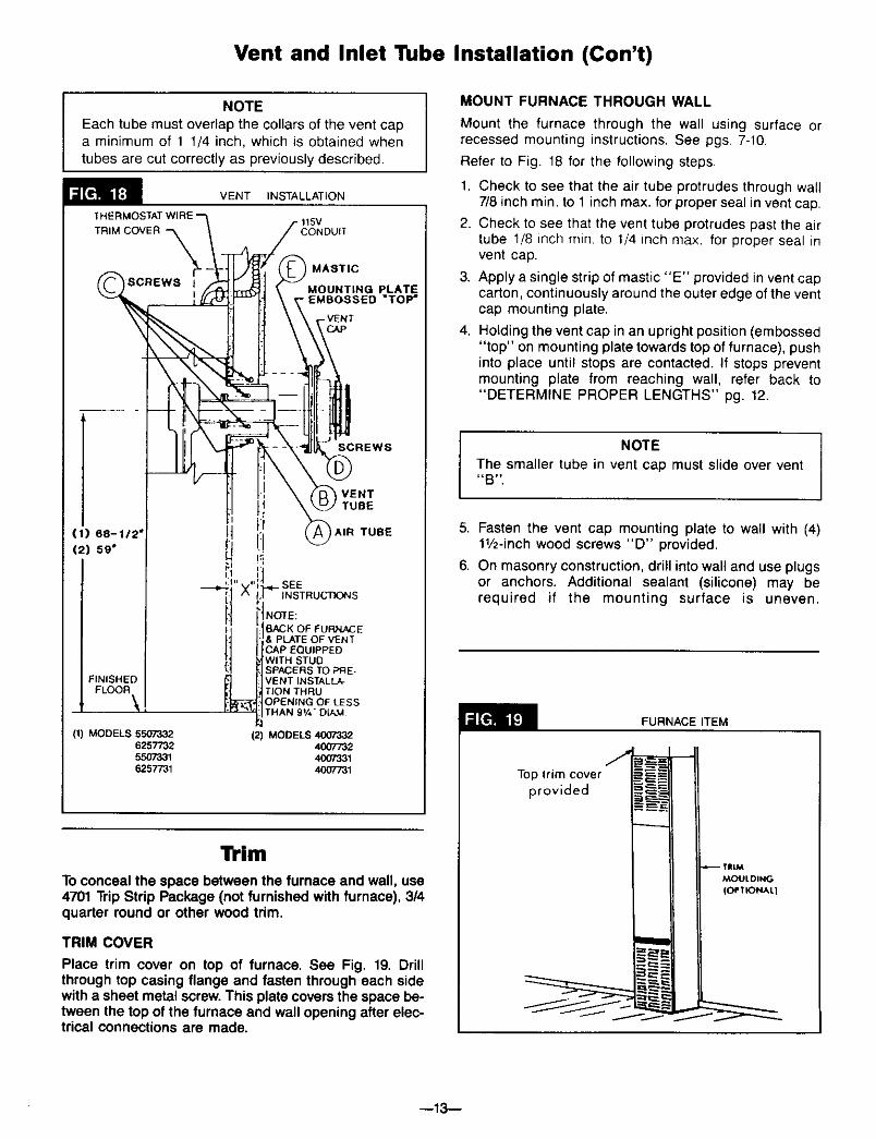
NOTE
Each tube must overlap the collars of the vent capa minimum of 1 1/4 inch, which is obtained whentubes are cut correctly as previously described.
VENT INSTALLATION
CONDUIT
(1) 68-112'
(2) 59"
FINISHEDFLOOR
\(1) MODELS 5507332
625773255O73316257731
MASTIC
MOUNTING PLATEEMSOSSED "TOP"
SCREWS
VENT
, TUBE
I:1 I,,. TUBE
SEEINSTRUCTIONS
NOTE:
BACK OF FURNACE_, PLATE OF VENT3AP EQUIPPED
WITH STUDSPACERS TO PRE-VENT INSTALLA-TION THRUOPENING OF LESSTHAN 91/4"DL_.M
(2) MODELS 4007332400773240073314007731
Trim
To conceal the space between the furnace and wall, use4701 Trip Strip Package (not furnished with furnace), 3/4quarter round or other wood trim.
TRIM COVER
Place trim cover on top of furnace. See Fig. 19. Drillthrough top casing flange and fasten through each sidewith a sheet metal screw. This plate covers the space be-tween the top of the furnace and wall opening after elec-trical connections are made.
MOUNT FURNACE THROUGH WALL
Mount the furnace through the wall using surface orrecessed mounting instructions. See pgs. 7-10.
Refer to Fig. 18 for the following steps.
1. Check to see that the air tube protrudes through wall7/8 inch min. to 1 inch max. for proper seal in vent cap.
2. Check to see that the vent tube protrudes past the airtube 1/8 inch rain. to 1/4 inch max. for proper seal invent cap.
3. Apply a single strip of mastic "E" provided in vent capcarton, continuously around the outer edge of the ventcap mounting plate.
4. Holding the vent cap in an upright position (embossed"top" on mounting plate towards top of furnace), pushinto place until stops are contacted. If stops preventmounting plate from reaching wall, refer back to"DETERMINE PROPER LENGTHS" pg. 12.
NOTE
The smaller tube in vent cap must slide over vent_B _.
5. Fasten the vent cap mounting plate to wall with (4)11/2-inch wood screws "D" provided.
6. On masonry construction, drill into wall and use plugsor anchors. Additional sealant (silicone) may berequired if the mounting surface is uneven.
FURNACEITEM
JTop trim cover
provided
.c::_
TRiM
MOULDING
(OPTIONAL}
--13--
Mounting Your Furnace
To obtain adequate clearance for fastening furnace or toinstall gas supply fittings, it may be necessary to removethe burner and control assembly as follows:
CAUTION
Be careful not to damage burner pan gasket whenremoving burner and control assembly.
1. Lay the furnace on its back for the following steps.
Remove burner compartment door by pulling door topout and up.
MODELS 4007332, 6257332,4007331, 5507331.
a. Remove screws holdhlg ignition control unit andcover to casing.
b. Remove (3) screws 'A' holding burner pan to upperheating element support (Fig. 21, pg. 15). Rotateburner pan toward front until (3) pins 'B' disengagefrom upper heating element support.
c. Remove necessary wire to free control module fromits mounting location. Mark or tag each wire re-moved for its exact reconnection (Fig. 22, pg. 15).
d. Remove burner and control assembly from furnace.
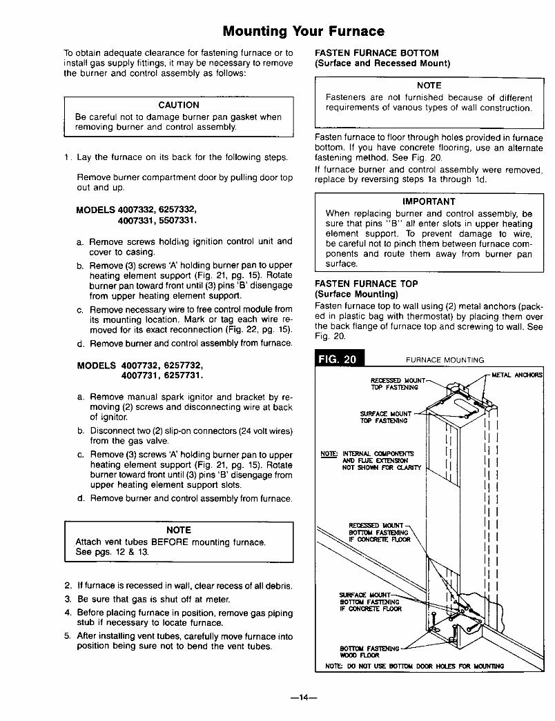
FASTEN FURNACE BOTTOM(Surface and Recessed Mount)
NOTE
Fasteners are not furnished because of differentrequirements of various types of wall construction.
Fasten furnace to floor through holes provided in furnacebottom. If you have concrete flooring, use an alternatefastening method. See Fig. 20.
If furnace burner and control assembly were removed,replace by reversing steps la through ld.
IMPORTANT
When replacing burner and control assembly, besure that pins "B" all enter slots in upper heatingelement support. To prevent damage to wire,be careful not to pinch them between furnace com-ponents and route them away from burner pansurface.
FASTEN FURNACE TOP(Surface Mounting)Fasten furnace top to wall using (2) metal anchors (pack-ed in plastic bag with thermostat) by placing them overthe back flange of furnace top and screwing to wall. SeeFig. 20.
MODELS 4007732, 6257732,4007731, 6257731.
a. Remove manual spark ignitor and bracket by re-moving (2) screws and disconnecting wire at backof ignitor.
b. Disconnect two (2) slip-on connectors (24 voltwires)from the gas valve.
c. Remove (3) screws 'A' holding burner pan to upperheating element support (Fig. 21, pg. 15). Rotateburner toward front until (3) pins 'B' disengage fromupper heating element support slots.
d. Remove burner and control assembly from furnace.
NOTE
Attach vent tubes BEFORE mounting furnace.See pgs. 12 & 13.
2. If furnace is recessed in wall, clear recess of all debris.
3. Be sure that gas is shut off at meter.
4. Before placing furnace in position, remove gas pipingstub if necessary to locate furnace.
5. After installing vent tubes, carefully move furnace intoposition being sure not to bend the vent tubes.
FURNACE MOUNTING
RECESSEDMOUNT
_REA_ MOUNTTOP FASTENING
NOT _-I0_1 FOR
II
II
BOI"rOMFAS'T1E]_NGWDOOFLDOR
NO'W.: DO NOT USE DOTrOM DOOR HOLES FOR MOLJNllNG
--14--

Mounting Your Furnace (ton't)
FASTEN FURNACE TOP(Recessed Mounting)
Fasten furnace top by drilling (2) holes through side flangefurnace top and securing with (2) screws or nails to wallstuds. See Fig. 20, pg. 14. CAUTION I
Be careful not to damage furnace components orwiring when drilling holes.
5 ,
L
o Io
Io
WlLUAMS IGNITION CONTROLPART NUMBER P3219t0
Gas Supply and PipingGas control valve, within the furnace, is shipped with aseal cover gas inlet tapping. Do not remove seal until readyto connect piping.
WARNING
DANGER OF PROPERTY DAMAGE,BODILY INJURY OR DEATH.
MAKE SURE THE FURNACE IS EQUIPPED TOOPERATE ON THE TYPE OF GAS AVAILABLE.MODELS DESIGNATED AS NATURAL GAS ARE TOBE USED WITH NATURAL GAS ONLY. FURNACEDESIGNATED FOR USE WITH LIQUEFIEDPETROLEUM (L.R) GAS HAVE ORIFICES SIZEDFOR COMMERCIALLY PURE PROPANE GAS.THEY CAN NOT BE USED WITH BUTANE OR AMIXTURE OF BUTANE AND PROPANE.
GAS SUPPLY
For Natural gas, the minimum inlet gas supply pressurefor the purpose of input adjustment is 5" water column.The Maximum inlet gas supply pressure is 7" watercolumn.
For L.IR gas, the minimum inlet gas supply pressure forthe purpose of input adjustment is 11" water column. Themaximum inlet gas supply pressure is 13" water column.
Gas pressures and input to the burners must not exceedthe rated input and pressure shown on the rating plate.On Natural Gas, the manifold pressure should be 4 inch-es water column. The manifold pressure should be 10.5inches water column for LP. Gas See pg. 18 for opera-tion above 2000 feet altitude. --15--
Orifice change may be required to suit gas supplied.Check with your local gas supplier.
ORIFICE SIZES
Furnace Technical Information, Page 26, shows thecorrect orifice sizes for the different input ratings whenusing Natural or L.R Gas.
GAS PIPING
The gas supply line must be of an adequate size tohandle the BTU/HR requirements and length of the runfor the unit being installed.Determine the minimum pipe size from Fig. 25, pg. 16, bas-ing the length of the run from the gas meter or sourceto the unit.
All piping must comply with local codes and ordinancesor with the National Fuel Gas Code (ANSI Z22&l-1988),whichever applies. In Canada: Follow CAN/CGA B149 In-stallation Code.
Refer to Fig. 23, pg. 16 for the general layout at the unit.It shows the basic fittings needed.The following rules apply:1. Use new, properly reamed pipe free from chips such
as steel or black iron pipe and fittings or otherapproved by local codes.
2. Do not thread pipe too far. Valve distortion or mal-function may result from excess pipe within control.Apply moderate amount of good quality dope to pipeonly, leaving 2 end threads bare. If LP gas installation,use compound resistant to action of liquefied petroleumgases.
3. Use ground joint unions.
Gas Supply and Piping (Con't)
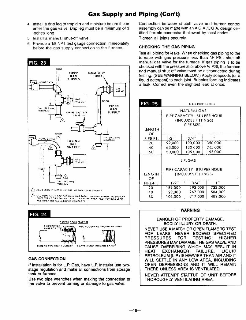
4. Install a drip leg to trap dirt and moisture before it canenter the gas valve. Drip leg must be a minimum of 3inches long.
5. Install a manual shut-off valve.
6. Provide a 1/8 NPT test gauge connection immediatelybefore the gas supply connection to the furnace.
DROp
I PIpIE D GROUNO JOINT
3, [ 62mml GAS
_tt_rMUM _ANUAL SHUT OFF SUPPLY
HOnlZON'r AL TUBING _It_IMUM;oF:
_ 31n 1762mmlM_NIMUM
_ALL BENDS IN METALLIC TUBING SHOULO 9E SMOOTH
_ CAUTION: SHOT OF€ THE MA_N CA$ SUPPLY BE,_ORE REMOVING ENO CAP
TO PREVI_NT GAS FROM F(LLINC THE WORK AAEA TE_T FOR GAS LEAK.
AGE WHEN INSTALLATION I_ COMPLETE
Connection between shutoff valve and burner controlassembly can be made with an A.G.A./C.G.A. design cer-tified flexible connector if allowed by local codes.Tighten all joints securely.
CHECKING THE GAS PIPING
Test all piping for leaks. When checking gas piping to thefurnace with gas pressure less than 1/2 PSI, shut offmanual gas valve for the furnace. If gas piping is to bechecked with the pressure at or above 1/2PSI, the furnaceand manual shut off valve must be disconnected duringtesting. (SEE WARNING BELOW.) Apply soapsuds (or aliquid detergent) to each joint. Bubbles forming indicatesa leak. Correct even the slightest leak at once.
GAS PIPE SIZES
NATURAL GAS
PIPE CAPACITY - BTU PER HOUR
(INCLUDES FITTINGS)PIPE SIZE.
LENGTHOF
PIPE-FT. I/2" 3/4" I"
20 92,000 190.000 350,00040 63.000 130,000 245.00060 S0,000 105,000 195,000
L.P, GAS
PIPE CAPACITY - BTU PER HOUR
LENGTH (INCLUDES FITTINGS)OF
PIPE-FT. 1/2" 3/4" 1"
20 189,000 393,000 732,00040 129.000 267,000 504,000
60 103,000 217.000 409,000
WARNING
PROP[R PtPtMG PRACTI¢_
2 IMPERFECT CONTRO L USE MODERATE AMOUNT OF DOPETHR£AD5
\THREAD PIPE RIGHT L_NGTH LEAVE 2 END THREADS 8ARE "_
GAS CONNECTION
If installation isfor L.R Gas, have L.R installer use two-stage regulation and make all connections from storagetank to furnace.
Use two pipe wrenches when making the connection tothe valve to prevent turning or damage to gas valve.
DANGER OF PROPERTY DAMAGE,BODILY INJURY OR DEATH.
NEVER USE A MATCH OR OPEN FLAME TO TESTFOR LEAKS. NEVER EXCEED SPECIFIEDPRESSURES FOR TESTING. HIGHERPRESSURES MAY DAMAGE THE GAS VALVE ANDCAUSE OVERFIRING WHICH MAY RESULT INHEAT EXCHANGER FAILURE. LIQUIDPETROLEUM (L.R) IS HEAVIER THAN AIR AND ITWILL SETTLE IN ANY LOW AREA, INCLUDINGOPEN DEPRESSIONS AND IT WILL REMAINTHERE UNLESS AREA IS VENTILATED.
NEVER ATTEMPT STARTUP OF UNIT BEFORETHOROUGHLY VENTILATING AREA.
--16--

Electrical Wiring
WARNINGDANGER OF PROPERTY DAMAGE,
BODILY INJURY OR DEATH.TURN OFF ELECTRIC POWER AT FUSE BOXOR SERVICE PANEL BEFORE MAKING ANYELECTRICAL CONNECTIONS.INSULATE WHERE NECESSARY.ALL LINE VOLTAGE AND GROUND CONNEC-TIONS MUST BE COMPLETED BEFOREELECTRICAL POWER IS RESTORED.
All electrical work must conform to your local codes andordinances or in their absence, with National ElectricalCode, ANSI/NFPA 70. If you are not familiar with wiringcodes, in general, have a competent electrician do this job.In Canada: Follow C22.1, Canadian Electrical Code.
CAUTION
Label all wires prior to disconnection when servicingcontrols. Wiring errors can cause improper anddangerous operation. Verify proper operation afterservicing.
JUNCTION BOX
Power supply connections are made inside the junctionbox in the upper left corner of the cabinet. See Fig.26.
CAUTION IDo not connect 115V service line to the gas controlvalve or wall thermostat.
ELECTRICAL CONNECTION
Connect 115V. conduit to top of furnace as shown in Fig.18, pg. 13. Remove screws holding junction box cover andtransformer for access to junction box. Remove the coverplate with transformer attached.
Pull supply wires through conduit and into junction box.Attach your 115V.supply wire to "LINE" factory wires. Usewire nuts provided.
Replace junction box cover and make final groundconnections with screws for plate cover.
Refer to paragraph covering GAS AND ELECTRICALSUPPLY OPENINGS, pg. 9. Follow Wiring Diagrams, pgs.27 and 28.
If you have any doubt regarding electrical hookup, or com-pliance with code or ordinace, consult your electricalinspector or a licensed electrician.
HELPFUL HINT
After wire nuts are screwed to wires, a small strip of elec-trical tape can be applied over wire nut at its base andonto wires to make a very solid connection.
GROUNDING
A ground lug is installed for the ground connection. Usea copper conductor (#AWG) from the unit to a groundedconnection in the electric service panel or a propedy drivenand electrically grounded ground rod.
ELECTRICAL POWER SUPPLY
A branch circuit including this furnace must not exceed15 amperes or run a separate 115V., 60 Hz., 15 Amperecircuit from a separate circuit breaker or fuse in your serv-ice panel to the furnace junction box. Do not run supplywires inside the furnace cabinet, except from the top ofcabinet down to junction box. Connect as shown in Fig. 26.
CONNECTING SUPPLY WIRING
WIRES MARKED LINEPUSH BACK INSIDEJUNC lION BOX
MAKE CONDUIT
CONNECTION HERE
_ ,,__ lO THERMOSTA"_ !!) AO,NE
MAKE WIRE CONNECTIONS
"J" BOX COVER PLATE_HOWN REMOVED)
TO APPROVED
GROUND
_(FIELD WIRED)
MOTOR GROUNI
FACTORY WIREDON TRANSFORMER TO GAS VALVE
LOW VOLTAGE CONNECTIONS
CAUTION
The Heat Anticipator WILL BURNOUT if 24 volts areapplied directly to thermostat by shorting out the gasvalve or primary control during testing or by incorrectwiring.
WALL THEMOSTAT WIRING
Run thermostat wire to the furnace.Connect thermostat to two wires marked "Thermostat"extending from top of furnace, using two wire nuts pro-vided. See Wiring Diagrams, pgs. 27 and 28. Refer to Fig.15, pg. 11, also,
Replace fan to original position on motor shaft, tighten-ing securely. Replace fan shroud, making sure it iscentered vertically on the fan.
Tighten screws securely.
Replace top front panel and secure with thumbscrew.
COMPLETE WIRING DIAGRAMS ON PAGES 27 AND 28.
--17--

Start-Up ProcedureStart the furnace using the procedures in sectionOPERATING YOUR FURNACE. Pages 19 thru 24.
WARNINGDANGER OF PROPERTY DAMAGE,
BODILY INJURY OR DEATH.LIQUIFIED PETROLEUM L.IR GAS IS HEAVIERTHAN AIR AND IT WILL SETTLE IN ANY LOWAREA, INCLUDING OPEN DEPRESSIONS ANDIT WILL REMAIN THERE UNLESS AREA ISVENTILATED.NEVER ATTEMPT STARTUP OF UNIT BEFORETHOROUGHLY VENTILATING AREA.
CHECK THE GAS INPUT (NATURAL GAS ONLY)WARNING
NATURAL GAS HEATING VALUE (BTU PER CUBICFOOT) CAN VARY SIGNIFICANTLY, THEREFORE,IT IS THE INSTALLER'S RESPONSIBILITY TO SEETHAT BTU INPUT TO THE FURNACE IS ADJUSTEDPROPERLY. FAILURE TO DO SO COULD CAUSEHEAT EXCHANGER FAILURE, ASPHYXIATION,FIRE OR EXPLOSION, RESULTING IN DAMAGE,BODILY INJURY OR DEATH. REFER TO THENATURAL FUEL GAS CODE (NFPA-54) TO BESURE THE FURNACE IS BURNING FUEL AT THEPROPER RATE.
Check the furnace operation as outlined in the followinginstructions. If any sparking, odors or unusual noises areencountered, shut off electric power immediately. Recheckfor wiring errors, or obstructions in or near fan motor.
CHECK GAS INPUT AND PRESSURESFor furnace located at elevations between sea level and2000 feet, the measured input must not be greater thanthe input shown on the rating plate of the furnace. Forelevations above 2000 feet, the measured input must notexceed the input of the rating plate reduced by 4 percentfor each 1000 feet that the furnace is above sea level.
Gas supply pressure and manifold pressure with the burn-ers operating must also be as specified on the rating plate.
Type of Gas Manifold Pressure, In. W.C. |Natural 4 ]L.P. 10.5
Rated input will be obtained on 2500 Btu propane at 10.5inch manifold pressure with factory-sized orifices. If LP gashaving a different heating value is supplied, orifices mustbe changed by a qualified service technician before thefurnace is operated.
CHECK THERMOSTAT
Check thermostat operation. When set above temperatureshown on the thermostat, the main burner should light.Make certain the thermostat turns off the furnace whenroom temperature reaches the selected setting and startsthe furnace when room temperature falls a few degrees.
SURE TH_ ANTICIPATORIS SET PROPERLY
ADJUST PILOT BURNER
NOTESTANDING PILOT MODELS ONLY
Pilot flame should surround 5/8 to 1/2 inch of thethermocouple tip. Toadjust, remove cap from pilotad-justing screw on gas valve. Turn screw counterclock-wise to increase flame, clockwiseto decrease. Replacecap. See Figs, 31, Page 25 and Fig. 32, Page 26.
CHECK THE MANIFOLD GAS PRESSUREA tapped opening is provided in the gas valve to facilitatemeasuring the manifold gas pressure. A "U Tube"manometer having a scale range from 0 to 12 inches ofwater should be used for this measurement. The manifoldpressure must be measured with the burner and pilotoperating, Any major changes in flow must be made bychanging the size of the burner orifice, Check with yourlocal gas supplier for proper orifice sizing.
Underfiring could cause inadequate heat, excessive con-densation or ignition problems. Overfiring could causesooting flame impingement or overheating of heatexchanger.
Before starting natural gas input check, obtain heatingvalue of gas (BTU per cubic foot) at standard conditionsfrom your local supplier. This factor is used in "Check theGas Input" section and procedure.
To measure the input using the gas meter, proceed asfollows:
1. Turn off gas supply to all other appliances exceptthe furnace.
2. With the furnace operating, time the smallest dial onthe meter for one complete revolution. If this is a 2cubic foot dial, divide the seconds by 2; if it is a 1cubic foot dial, use the time in seconds as is. Thisgives the seconds per cubic foot of gas being deliveredto the furnace.
3. Assuming natural gas with a heating value of 1000 BTUper cubic foot and 34 seconds per cubic foot asdetermined by step (2), then:Input = 1,000 x 3,600 + 34 =106,000 BTU Per Hour
This measured input must not be greater than theinput indicated on the rating plate of the furnace.
4. Relight all other appliances turned off in step 1 above.Be sure all pilot burners are operating.
THERMOSTAT (TYPICAL)
SQUEEZE FIRMLYBOTH SIDESAND LIFT TOREMOVE COVER
WARNINGDANGER OF IGNITION FLASH
AND EYE INJURY OR BLINDNESSPROTECT YOUR EYES. NEVER ATTEMPT TOLIGHT PILOT WITH GAS CONTROL VALVE KNOBIN "ON" POSITION. FLASH BACK COULDOCCUR.
--18--
Operating Your Furnace
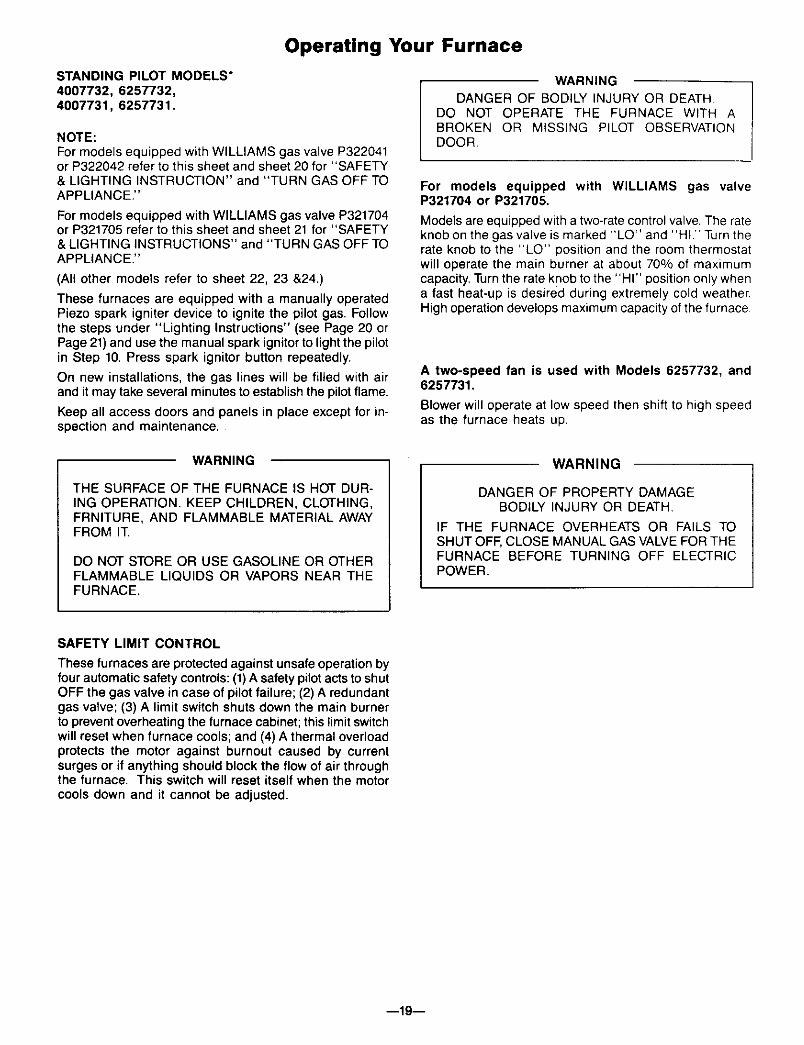
STANDING PILOT MODELS"
4007732, 6257732,4007731, 6257731.
NOTE:For models equipped with WILLIAMS gas valve P322041or P322042 refer to this sheet and sheet 20 for "SAFETY& LIGHTING INSTRUCTION" and "TURN GAS OFF TOAPPLIANCE."
For models equipped with WILLIAMS gas valve P321704or P321705 refer to this sheet and sheet 21 for "SAFETY& LIGHTING INSTRUCTIONS" and "TURN GAS OFF TOAPPLIANCE."
(All other models refer to sheet 22, 23 &24.)
These furnaces are equipped with a manually operatedPiezo spark igniter device to ignite the pilot gas. Followthe steps under "Lighting Instructions" (see Page 20 orPage 21)and use the manual spark ignitor to light the pilotin Step 10. Press spark ignitor button repeatedly.
On new installations, the gas lines will be filled with airand it may take several minutes to establish the pilot flame.
Keep all access doors and panels in place except for in-spection and maintenance.
WARNINGDANGER OF BODILY INJURY OR DEATH.
DO NOT OPERATE THE FURNACE WITH ABROKEN OR MISSING PILOT OBSERVATIONDOOR.
For models equipped with WILLIAMS gas valveP321704 or P321705.
Models are equipped with a two-rate control valve. The rateknob on the gas valve is marked "LO" and "HI." Turn therate knob to the "LO" position and the room thermostatwill operate the main burner at about 70% of maximumcapacity. Turn the rate knob to the "HI" position only whena fast heat-up is desired during extremely cold weather.High operation develops maximum capacity of the furnace
A two-speed fan is used with Models 6257732, and6257731.
Blower will operate at low speed then shift to high speedas the furnace heats up.
WARNING
THE SURFACE OF THE FURNACE IS HOT DUR-ING OPERATION. KEEP CHILDREN, CLOTHING,FRNITURE, AND FLAMMABLE MATERIAL AWAYFROM IT.
DO NOT STORE OR USE GASOLINE OR OTHERFLAMMABLE LIQUIDS OR VAPORS NEAR THEFURNACE.
WARNING
DANGER OF PROPERTY DAMAGEBODILY INJURY OR DEATH.
IF THE FURNACE OVERHEATS OR FAILS TOSHUT OFF, CLOSE MANUAL GAS VALVE FOR THEFURNACE BEFORE TURNING OFF ELECTRICPOWER.
SAFETY LIMIT CONTROL
These furnaces are protected against unsafe operation byfour automatic safety controls: (1)A safety pilot acts to shutOFF the gas valve in case of pilot failure; (2) A redundantgas valve; (3) A limit switch shuts down the main burnerto prevent overheating the furnace cabinet; this limit switchwill reset when furnace cools; and (4) A thermal overloadprotects the motor against burnout caused by currentsurges or if anything should block the flow of air throughthe furnace. This switch will reset itself when the motorcools down and it cannot be adjusted.
--19--

FOR YOUR SAFETY, READ BEFORE LIGHTING
I WARNING: If you do not follow these instructions exactly, a fire or explosion Imay result causing property damage, personal injury or loss of life. IA. This appliance has a pilot which must be lighted by
hand, When lighting the pilot, follow these instructions
exactly.
B. BEFORE LIGHTING smell around the appliance areafor gas. Be sure to smell next to the floor because somegas is heavier than air and will settle on the floor.
WHAT TO DO IF YOU SMELL GAS
• Do not try to light any appliance or strike a match.• Do not touch any electric switch; do not use any
phone in your building.• Immediately call your gas supplier from a neighbor's
phone. Follow the gas supplier's instructions.
C.
D.
• If you cannot reach your gas supplier, call the firedepartment.
Use only your hand to push in or turn the gas controlknob. Never use tools. If the knob will not push in orturn by hand, don't try to repair it, call a qualified serv-ice technician, Force or attempted repair may result in afire or explosion,
Do not use this appliance if any part has been underwater. Immediately call a qualified service technician toinspect the appliance and to replace any part of thecontrol system and any gas control which has beenunder water.
LIGHTING INSTRUCTIONS
1. STOP! Read the safety information above.2. Set the thermostat to lowest setting.3. Turn off all electric power to the appliance.4. Remove control access panel.5. Turn gas control knob clockwise _ to "OFF".
GASCONTROLKNOB
RESETBUTTON
6. Wait five (5) minutes to clear out any gas then smell forgas, including near the floor. If you then smell gas, stop!Follow "B" in the safety information above. If you don'tsmell gas, go to next step.
7. Loosen wingnut and open pilot observation door (ifequipped).
8. Find pilot--follow metal tube from gas control, The pilotis mounted on side of burner.
9. Turn knob on gas control counterclockwise J_to "PILOT,"
10. Push in red reset button THERMO-_1 ,[_,=all the way and hold in. COUPLEImmediately light thepilot. Continue to hold
the red reset button in for about PILOT(1) minute after the pilot is lit, Release BURNERbutton and it will pop back up. Pilot shouldremain lit. If it goes out, repeat steps 5 through 10.
• If button does not pop up when released, stop andimmediately call your service technician or gassupplier,
• If the pilot will not stay lit after several tries, turnthe gas control knob to "OFF" and call your servicetechnician or gas supplier.
11. Close pilot observation door, tighten wingnut(if equipped),
12. Turn gas control knob counterclockwise _ to "ON",Knob can be turned to "ON" only if red reset button isup.
13. Replace control access panel.
14. Turn on all electric power to the appliance.15. Set thermostat to desired setting.
TO TURN OFF GAS TO APPLIANCE
1. Set the thermostat to lowest setting.
2. Turn off all electric power to the appliance if service is to be performed.
3. Remove control access panel.
4. Push in gas control knob slightly and turn clockwise _ to "OFF". Do not Force.
5. Replace control access panel.
WARNING: DUE TO HIGH SURFACE TEMPERATURES -- KEEP CHILDREN, CLOTHING,FURNITURE OR ANY COMBUSTIBLE MATERIAL AWAY FROM FURNACE.
IMPORTANT: KEEP BURNER AND CONTROL COMPARTMENT CLEAN.
--20--

FOR YOUR SAFETY, READ BEFORE LIGHTING
WARNING: If you do not follow these instructions exactly, a fire or explosionmay result causing property damage, personal injury or loss of life,
A. This appliance has a pilot which must be lighted byhand. When lighting the pilot, follow these instructions
exactly.
B. BEFORE LIGHTING smell around the appliance area
for gas. Be sure to smell next to the floor because somegas is heavier than air and will settle on the floor.
WHAT TO DO IF YOU SMELL GAS
• Do not try to light any appliance or strike a match.• Oo not touch any electric switch; do not use any
phone in your building.• immediately call your gas supplier from a neighbor's
phone, Follow the gas supplier'a Instructions.
C.
O.
• If you cannot reach your gas supplier, call the firedepartment.
Use only your hand to push in or move the selectorarm. Never use tools. If the arm will not push in ormove by hand, don't try to repair it, call a qualifiedservice technician. Force or attempted repair may resultin a fire or explosion.
Do not use this appliance if any part has been underwater. Immediately call a qualified service technician toinspect the appliance and to replace any part of thecontrol system and any gas control which has beenunder water.
LIGHTING INSTRUCTIONS
1. STOP! Read the safety information above.2. Set the thermostat to lowest setting,3. Turn off all electric power to the appliance.4. Remove control access panel.5. From "ON" position, depress and move selector
arm on gas control to "OFF" position, Do not force.
GAS CONTROLSELECTORARM SHOWNIN =OFF"POSITION
6. Wait five minutes to clear out any gas then smell for gas,including near the floor. If you then smell gas, stop! Follow"B'" In the safety information above. If you don't smellgas, go to next step.
:7. Loosen wingnut and open pilot observation door (ifequipped).
8.
9.
f0.
Find pilot--follow metal tube from gas control. The pilotis mounted on side of burner.
Hold lighted match at pilotburner.
Move selector arm to"SET" postlon and lightpilot, Hold in "SET" positionfor 1/2 minute after pilot is lit.NOTE: Sufficient time must be allowed PILOTfor pilot flame to heat thermocouple BURNERand hold safety magnet in locked-up position,also, time must be allowed for air to be purgedfrom gas lines during first starting operation.
11. Release selector arm, and if pilot remains lit, moveselector arm to "ON" position,
• If the pilot will not stay lit after several tries, movethe selector arm to "OFF" and call your servicetechnician or gas supplier.
12. Close pilot observation door and tighten wingnut(if equipped).
13. Replace control access panel.
14. Turn on all electric power to the appliance.
15. Set thermostat to desired setting.
TO TURN OFF GAS TO APPLIANCE
1. Set the thermostat to lowest setting.
2. Turn off all electric power to the appliance if service is to be performed.
13. Remove control access panel.4. From "ON" position, depress and move selector arm on gas control to "OFF" position. Do not force.
5. Replace control access panel.
WARNING: DUE TO HIGH SURFACE TEMPERATURES -- KEEP CHILDREN, CLOTHING,FURNITURE OR ANY COMBUSTIBLE MATERIAL AWAY FROM FURNACE.
IMPORTANT: KEEP BURNER AND CONTROL COMPARTMENT CLEAN.
--21--

Operating Your FurnaceELECTRONIC IGNITION MODELS*4007332, 5507332,4007331, 5507331.
NOTE:For models equipped with WILLIAMS gas valve P322043or P322044 refer to this sheet and sheet 23 for "SAFETY& LIGHTING INSTRUCTION" and "TURN GAS OFF TOAPPLIANCE."
For models equipped with WILLIAMS gas valve P321897or P321898 refer to this sheet and sheet 24 for "SAFETY& LIGHTING INSTRUCTIONS" and "TURN GAS OFF TOAPPLIANCE."
(All other models refer to sheet 19, 20 & 21.)
THE FURNACE WORKS LIKE THIS:
1. Thermostat turns on the control module.
2. Automatic relight system (in module) opens gas valveand electronically ignites pilot. After pilot flame hasbeen established and proven by the control module,main gas valve circuit opens and pilot lights mainburners.
3. Heat builds up in the furnace and starts the fan. Theheated air comes out the front bottom Iouvered panelat floor level.
4. When the thermostat setting is reached, it shuts off themain burner.
5. The fan runs until the heat is removed from furnace,then it turns off.
SAFETY LIMIT CONTROL
These furnaces are protected against unsafe operation bythree automatic safety controls: (1)The electronic ignitionsystem; (2) A limit switch shuts down the main burner toprevent overheating the furnace cabinet; this limit switchwill reset when furnace cools; (3) A thermal overload pro-tects the motor against burnout caused by current surgesor if anything should block the flow of air through the fur-nace, the switch will turn the main burner off. When motorcools down, this switch will reset itself. This switch can-not be adjusted.
WARNINGDANGER OF BODILY INJURY OR DEATH.
DO NOT OPERATE THE FURNACE WITH ABROKEN OR MISSING PILOT OBSERVATIONDOOR.
For models equipped with WILLIAMS gas valveP321897 or P321898.
Models are equipped with a two-rate control valve. The rateknob on the gas valve is marked "LO" and "HI." Turn therate knob to the "LO" position and the room thermostatwill operate the main burner at about 70% of maximumcapacity. Turn the rate knob to the "HI" position only whena fast heat-up is desired during extremely cold weather.High operation develops maximum capacity of the furnace.
A two*speed fan is used with Models 5507332, and5507331.
Blower will operate at low speed then shift to high speedas the furnace heats up.
WARNING
DANGER OF PROPERTY DAMAGEBODILY INJURY OR DEATH.
IF THE FURNACE OVERHEATS OR FAILS TOSHUT OFF, CLOSE MANUAL GAS VALVE FOR THEFURNACE BEFORE TURNING OFF ELECTRICPOWER.
WARNING
THE SURFACE OF THE FURNACE IS HOT DUR-ING OPERATION. KEEP CHILDREN, CLOTHING,FURNITURE, AND FLAMMABLE MATERIAL AWAYFROM IT.
DO NOT STORE OR USE GASOLINE OR OTHERFLAMMABLE LIQUIDS OR VAPORS NEAR THEFURNACE.
--22--
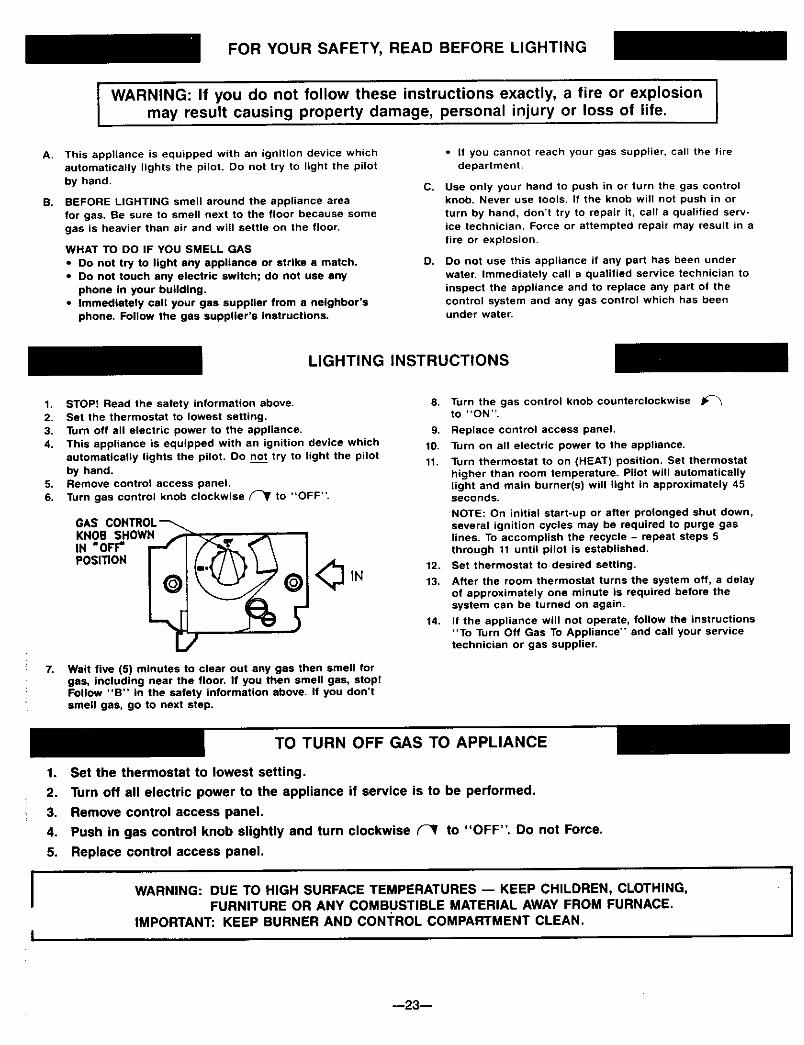
FOR YOUR SAFETY, READ BEFORE LIGHTING
WARNING: If you do not follow these instructions exactly, a fire or explosionmay result causing property damage, personal injury or loss of life.
A.
B.
This appliance is equipped with an ignition device whichautomatically lights the pilot. Do not try to light the pilot
by hand.
BEFORE LIGHTING smell around the appliance area
for gas. Be sure to smell next to the floor because somegas is heavier than air and will settle on the floor.
WHAT TO DO IF YOU SMELL GAS
• Do not try to light any appliance or strike a match.• Do not touch any electric switch; do not use any
phone In your building.• Immediately call your gas supplier from a neighbor's
phone. Follow the gas suppller's Instructions.
C.
O.
• if you cannot reach your gas supplier, call the firedepartment.
Use only your hand to push in or turn the gas controlknob. Never use tools. If the knob will not push in or
turn by hand, don't try to repair it, call a qualified serv-ice technician. Force or attempted repair may result in a
fire or explosion.
Do not use this appliance if any part has been underwater. Immediately call a qualified service technician toinspect the appliance and to replace any part of thecontrol system and any gas control which has beenunder water.
LIGHTING INSTRUCTIONS
1. STOP! Read the safety information above.2. Set the thermostat to lowest setting.3. Turn off all electric power to the appliance,4. This appliance is equipped with an ignition device which
automatically lights the pilot. Do not try to light the pilotby hand.
5. Remove control access panel.6. Turn gas control knob clockwise (_ to "OFF".
GAS CONTROL --'_.KNOB SHOWN .,IN "OFF" r -r
POSITION _
/
IN
Wait five (5) minutes to clear out any gas then smell forgas, including near the floor. If you then smell gas, stop!Follow "B" in the safety information above. If you don'tsmell gas, go to next step.
S. Turn the gas control knob counterclockwiseto "ON".
9. Replace control access panel.
10. Turn on all electric power to the appliance.
11. Turn thermostat to on (HEAT) position. Set thermostathigher than room temperature. Pilot will automaticallylight and main burner(s) will light in approximately 45seconds.
NOTE: On initial start-up or after prolonged shut down,several ignition cycles may be required to purge gaslines. To accomplish the recycle - repeat steps 5through 11 until pilot is established.
12. Set thermostat to desired setting.
13. After the room thermostat turns the system off, a delayof approximately one minute is required before thesystem can be turned on again.
14. If the appliance will not operate, follow the instructions"To Turn Off Gas To Appliance" and call your servicetechnician or gas supplier.
II
TO TURN OFF GAS TO APPLIANCE
1. Set the thermostat to lowest setting.
2. Turn off all electric power to the appliance if service is to be performed.
3. Remove control access panel.
4. Push in gas control knob slightly and turn clockwise _ to "OFF". Do not Force.
5. Replace control access panel.
WARNING: DUE TO HIGH SURFACE TEMPERATURES -- KEEP CHILDREN, CLOTHING,FURNITURE OR ANY COMBUSTIBLE MATERIAL AWAY FROM FURNACE.
IMPORTANT: KEEP BURNER AND CONTROL COMPARTMENT CLEAN. I--23--

FOR YOUR SAFETY, READ BEFORE LIGHTING
WARNING: If you do not follow these instructions exactly, a fire or explosionmay result causing property damage, personal injury or loss of life.
A. This appliance is equipped with an ignition device which
automatically lights the pilot. Do not try to light the pilotby hand.
B. BEFORE LIGHTING smell around the appliance areafor gas. Be sure to smell next to the floor because somegas is heavier than air and will settle on the floor.
WHAT TO DO iF YOU SMELL GAS
• DO not try to light any appliance or strike a match.• Do not touch any electric switch; do not use any
phone in your building.• Immediately call your gas supplier from a neighbor's
phone. Follow the gas supplier's instructions.
C.
O.
• If you cannot reach your gas supplier, call the firedepartment.
Use only your hand to push in or move the selector
arm. Never use tools. If the arm will not push in ormove by hand, don't try to repair it, call a qualifiedservice technician. Force or attempted repair may resultin a fire or explosion.
Do not use this appliance if any part has been underwater. Immediately call a qualified service technician to
inspect the appliance and to replace any part of thecontrol system and any gas control which has beenunder water.
LIGHTING INSTRUCTIONS
1. STOP! Read the safety information above.2. Set the thermostat to lowest setting.3. Turn off all electric power to the appliance.4. This appliance is equipped with an ignition device which
automatically lights the pilot. Do not try to light the pilotby hand.
5. Remove control access panel.6. From "ON" position, depress and move selector arm on
gas control to "OFF" position. Do not force.
GAS CON'I_OLSELECTORARM SHOWNIN "OFF"POSITION
7. Wait five (5) minutes to clear out any gas then smell forgas, including near the floor. If you then smell gas, atop!Follow "B" in the safety information above. If you don'tsmell gas, go to next step.
8. Move selector arm to "ON" position.
9. Replace control access panel.
10. Turn on all electric power to the appliance.
11. Turn thermostat to on (HEAT) position. Set thermostathigher than room temperature. Set thermostat higherthan room temperature. Pilot will automatically lightand main burner(s) will light in approximately 45seconds.
12.
13.
14.
NOTE: On initial start-up or after prolonged shut down,several ignition cycles may be required to purge gaslines. To accomplish the recycle - repeat steps 6through 11 until pilot is established.
Set thermostat to desired setting.
After the room thermostat turns the system off, a delayof approximately one minute is required before thesystem can be turned on again.
If the appliance will not operate, follow the instructions"To Turn Off Gas To Appliance" and call your servicetechnician or gas supplier.
TO TURN OFF GAS TO APPLIANCE
1. Set the thermostat to lowest setting.
2. Turn off all electric power to the appliance if service is to be performed.
3. Remove control access panel.
4. From "ON" position, depress and move selector arm on gas control to "OFF" position. Do not force.
5. Replace control access panel.
WARNING: DUE TO HIGH SURFACE TEMPERATURES -- KEEP CHILDREN, CLOTHING,FURNITURE OR ANY COMBUSTIBLE MATERIAL AWAY FROM FURNACE.
IMPORTANT: KEEP BURNER AND CONTROL COMPARTMENT CLEAN.
--24--

How To Care For Your Furnace
WARNINGDANGER OF BODILY INJURY OR DEATH
TURN OFF ELECTRIC POWER SUPPLY ATDISCONNECT SWITCH, FUSE BOX OR SERVICEPANEL BEFORE REMOVING ANY DOORS ORACCESS OR SERVICE PANELS FROM UNIT.
CABINET FINISH
Clean cabinet with damp rag. Never use abrasive cleaners.Cabinets are finished in heat resistant baked enamel - DONOT refinish with wail paint.
COMBUSTION AND VENTILATION AIR
The combustion and ventilation air supply must not beblocked.
Do not put anything in or on the furnace cabinet.
For better circulation and more effective heating, do notplace obstructive furniture closer than four feet to the frontof the cabinet or two feet to the side of the cabinet.
FURNACE AREA
Keep the area near the furnace clear and free from com-bustible materials, gasoline, and other flammable liquidsand vapors.
ANNUAL UPKEEP NEEDED
It is recommended that a qualified service technician per-form these checks at the beginning of each heatingseason.
CLEANING AND OILING
Shut off electricity, then remove cabinet door and frontpanel. Clean any lint or dirt from fan blades, fan motor,and exposed air passages. Use a brush. Put 5 drops ofSAE 20 oil in each of the two cups or oil tubes on the fanmotor, See Fig. 30, below.
MOTOR OIL HOLES
FAN
MOIOR
Oft Ius{S
OR
Oft CUPS
ON EACH
END OF
MOIOR
PILOT BURNER
Light pilot using instructions in OPERATING YOURFURNACE (on Pages 19 thru 24, depending on yourmodel).Pilot flame should surround 5/8 to 1/2 inch of the thermo-couple tip. Refer to Fig. 32, Page 26. If flame needsadjusting, do it as follows:
ADJUST PILOT BURNER
See Fig. 31 and 32. (Page 26)1. Remove screw cover over pilot adjusting screw.
2. Insert small screwdriver, Adjust flame as needed. Turnscrew counterclockwise ( _ ) to increase flame,clockwise ( _ ) to decrease.
3. Turnthermostat to highest setting. Main burners shouldlight quickly and smoothly. Turn thermostat to lowestsetting. Main burners should go out. Pilot should re-main lit except for electronic ignition models.
4. Replace screw cover over pilot adjusting screw.
BURNER FLAME
Start the furnace and let it operate about 10 minutes thenlook at the burner flame. Flames should be soft and blue,see Fig. 31. If flames appear abnormal, contact the gascompany or a qualified service technician immediately.
VENTING SYSTEM
Make sure that no parts of the vent air system are block-ed, rusted or damaged (including joint gaskets). Clean orreplace before using furnace. See Page 12 and 13 forproper assembly and reseating of vent-air system.
--25--

How To Care For Your Furnace (ton't)
BURNER CLEANING
Check burner. If cleaning is required, contact a qualifiedservice technician to clean and service burner.
WARNING
DANGER OF BODILY INJURY OR DEATHMAKE SURE ELECTRIC POWER AND GASSUPPLY ARE OFF BEFORE REMOVING PANELSOR DOORS, ETC.
Disconnect Gas line inside cabinet.
Remove three screws from the front of the combustionchamber bottom panel and drop assembly down. Cleaninside the combustion chamber and the burner with a shoptype vacuum cleaner.To remove burners remove screw from end of burner andslide burner out of bracket (may be necessary to slightlyspring bracket).
Inspect the Burner Box gasket. Replace if damaged.
Replace burner assembly and control assembly by re-versing the above procedures.
SENSOR
SLtGHTORANGE TIP
NATURAL GASELECTnODE TYPICAL
- TYPICAL BLUE CONE ,_A / BLUE CONE
[ L P GAS _,_(_l_ NATURAL
BURNER
CASTING
Furnace Technical Information
MODEL
NUMBER
4007332
4007331
4007732
4007731
5507332
5507331
6257732
6257731
TYPEGAS
NAT
L.P.
NAT
L.P.
NAT
L.P.
NAT
L.P.
**RATINGIN BTUH
INPUT HTG.CAPAC.
32,000
32,000
32,000
32,000
44,000
44,000
5O,0OO
50,000
DRILL DEC.
#34 .1110
#50 .0700
#34 ,1110
#50 .0700
#42 .0935
#54 .0550
#39 .0995
#53 .0595
40,000
40,000
40,000
40,000
55,000
55,000
62,500
62,500
MAIN BURNER ORIFICE
QTY.
1
1
1
1
2
2
2
2
**For elevations above 2000 feet reduce ratings 4% for each 1000 feet above sea level.***Btuh = British Thermal Units per hour
The efficiency rating of these appliances is a product thermal efficiency rating determined under continuous operatingconditions and was determined independently of any installed system.
--26--

WIRING DIAGRAMS FOR MODELS
4007732 and 4007731 6257732 and 6257731
FOR 40M B.T.U.FAN TYPE DIRECT VENT WALL FURNACE
WITH CONTINUOUS PILOT CONTROL SYSTEM
IUMIT SWITCH' (_"I1RAN S.
_____________.___________j--HGASV_W ITHERMOCOUPLE
J_(;IE3_D NOTE:
m FACTC_Y _ lINE _OLTAGE, 1 Ifanyoftheoriginalwireassupplied-- FACTORY _ LOW VOLTAGF.. with the appliance has to be replac-
11/_4 _ CONNECT "i_MINAL ed, use only 18 Ga., 4/64 insulation,FACI'(_T" _RING* 105 ° C. AWM copper wire or its
_tllRE CO_CTOI_ F01t FAC_I101_Y equivalent 115V- 60Hz -lessthan3 amps
_NG LINE VOLTAGE. 2 MOTOR IS THERMALLY OVER-_ _ LOW V0LTAilI_ LOAD PROTECTED
115%L60Hz - LESS THAN 3 AMPS
THERMOSTAT
r
• 1
LGAS VALVE
115V 60H7.
HOTI ]NEUT"
A
_ THERMC¢-.,'_N.IPLE
FOR 62.5M B.T.U.FAN TYPE DIRECT VENT WALL FURNACE
WITH CONTINUOUS PILOT CONTROL SYSTEM
L1 __ 115v 60HZ , L2
HOT| Hf NEUT
TOTHERMOSTAT _ [_ GAS VALVE +
L___THERMOCOUPLE
LEGEND NOTE:
m FACTORy _ UNE VOLTAGE. 1. Ifanyoftheoriginalwiteassupplied-- FAI_[IO_y _ LOW "YOLTAG_* with the appliance has to be replac-
1/4. QUICKCONNECTT_MZNAL ed, use only 18Ga., 4/64 insulation,f'(_ FAt_O_ " _R]NG. 105° C AWM copper wire or ils
• f_R£ CONNECTOR FOR FACTORY equivalent 115v - 60Hz - less thanWIRING LINE VOLTAGE. 3 amps
MOTOR IS THERMALLY OVER-_ _INAL LOW VOLTAGE. 2. LOAD PROTECTED
115V.60Hz - LESS THAN 3 AMPS.
B_CK
BLiU_
BI.gE_K'O_ F(__
UMIT
_ s_Ta_
THERMOSTAT
f
THERMOCOUPLEG_ V_
--27--

WIRING DIAGRAMS FOR MODELS
4007332 and 4007331 5507332 and 5507331
FOR 40M B.T.U.FAN TYPE DIRECT VENT WALL FURNACE
WITH INTERMtTFENT IGNITION CONTROL SYSTEM
ul luHOTi_ 115VS0HZ - I N_.UT
_ O- --/ TR _ PV(P) TL/ SF_NSO- PV,,1WV(c) ,--/ PV O, Mv(u)
INTERMII"R_T IGN.CONTROL MODULE
LEGI0_ID_FACTORy _RED LINE VOLTAQF--- FACTQ_qY_ LOWVOLTAGE.I--3 1/4 QUICKCON_C'r TERM1NALFOR FACTORYI_NG.
WIRECONNECTORFOR FACTORY_li_lP- LINE V(_.TAaE,
_ _INAL LOW VOLTAGE.
NOTE:
1. If any of the original wire as suppliedwith the appliance has to be replec-ed, use only 18 Ga. 4/64 insulation,
105= C AWM copper wire or ilsequivalent 115V - 60Hz - less Ihan3 amps
2, MOTOR IS THERMALLY OVER=LOAD PROTECTED,115V, 60Hz - LESS THAN 3 AMPS
1HERMOSTAT 115V 60HZ
HOT NEUT.
FAN
FOR 55M BT.U.FAN TYPE DIRECT VENT WALL FURNACE
WITH INTERMITI-ENT IGNITION CONTROL SYSTEM
1.1 |. 115V8ONZ .| L2HOT ! S_f)R _ | NEUT
L_r_115V I IT.____.__T. - _eJ....,o ru_LIMIT SWITCH ._ m,_,a, SE_ISOR
GND
s_so_ ?-ioFv/_v(c) "--PV Ol--- .-'r-lOIMV (_)THOl_ IF" cAs
MV (Z)-_ -'J I VALV_
ION___ --
IN'W_RMII"TF_NTIGN.CONTROLMODULE
_L_E_FACTORY_ lINE VOLTA_E,-- YA_ _ LOW VOLTAGE.
1/4 QUICKCONNECTFORF_Y
_ CONNECqORFOR FACTORYtiRiNg MNE VOLTA_..
(d_ _ _ LOWVOLTAGE.
NOTE:
1. If any of the original wire as suppliedwith the opp_lence has to b_ replec*ed, use only 18 Ga., 4/64 insulation,105° C. AWM copper w=re ot itsequivalent 115V - 60Hz. - less than3 amps.
2. MOTOR IS THERMALLY OVER-LOAD PROTECTED.115M 60Hz - LESS THAN 3 AMPS
31"IERMOSTAT 115V 60HZ
HOT I NEUT.
_.-c_
--28--
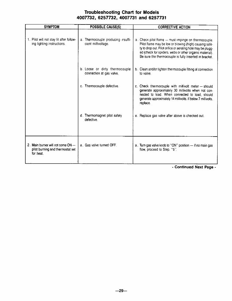
Troubleshooting Chart for Models4007732, 6257732, 4007731 and 6257731
SYMPTOM
1. Pilotwill not staylit afterfollow-ing lighting instructions.
2. MainburnerwillnotcomeON--pilotburningandthermostatsetfor heat.
POSSIBLECAUSE(S)
a. Thermocoupleproducinginsuffi-cientmillivoltage.
b. Loose or dirty thermocoupleconnectionat gas valve.
c. Thermocoupledefective.
d. Thermomagnetpilotsafetydefective.
a. Gas valveturnedOFE
CORRECTIVEACTION
a. Checkpilot flame-- mustimpingeon thermocouple.Pilotflamemaybe lowor blowing(high)causingsafe-ty todropout.Pilotorificeoraeratingholemaybeplugg-ed(checkforspiders,websorotherorganicmaterial).Besurethe thermocoupleis fully insertedinbracket.
b. Cleanand/ortightenthermocouplefittingatconnectionto valve
C, Check thermocouplewith millivolt meter--shouldgenerateapproximately30 millivoltswhen not con-nected to load. When connectedto load, shouldgenerateapproximately14millivolts,if below7 millivolts,replace.
e. Replacegasvalveafteraboveis checkedout.
a. Turngasvalveknobto "ON" position-- if nomaingasflow,proceedto Step."b".
- Continued Next Page -
--29--

Troubleshooting Chart for Models4007732, 6257732, 4007731 and 6257731 (Continued)
SYMPTOM
2 Mainburnerwill notcomeon --pilotburningandthermostatsetfor heat (continued)
3. BurnercomesON,butgoesOFFbeforeblowerturns ON."
POSSIBLECAUSE(S)
b Electric powerto furnaceturnedOFE
c. Low voltagetransformeror limitswitchdefective
d. Wallthermostatdefective.
e. Burnerorificeplugged.
f. Gas valvedefective.
a. Defectivewiring.
b. Defectiveswitch.
c. Defectivemotor(2-speed)
d. Defectivemotor(t-speed).
CORRECTIVEACTION
b. Checkfor linevoltageatfurnace-- if okayandnomaingas flow,proceedto Step"c".
C. Checkfor 24volts at the lowvoltageterminalsof thetransformer.If no voltage,turn OFFelectricpowertofurnace.Removeonewirefromlimitswitchandcheckfor continuityacrossbothterminals.No continuity--replacelimitswitch.Witha goodlimitswitchback inthe circuit andthe electric powerturnedON-- if novoltage,replacetransformer.NOTE:Beforereplacingthetransformeror limitswitch,checkwiringforlosecon-nectionsorbrokenwiresandrepairasneeded.Ifvoltageis presentat transformer,proceedto Step "d".
d. With thermostatset for heat(contactsclosed),checkfor voltageat terminalson gasvalve.If no voltageispresent,replacedefectivethermostat.NOTE:Beforereplacingthermostat,besureto checkwiringfromfur-nacetothermostatforlooseconnectionsorbrokenwiresandreplaceas needed.Ifvoltageis presentat terminalsongasvalveandstillno gas flowto mainburners,proceedto Step"e".
e. Cleanor replaceorifice-- if okayandstillnogasflowto mainburners,proceedto Step "f".
f. Replacedefectivegas valve.
a. Turnoff electricpowerto furnace.Removetop frontpanel,fan shroudand blowerwheel.Referto wiringdiagram and check all wiring inside junction box.Removecenterfrontpanelandcheckall wiringinsideswitchbox containingfan, limitandselectorswitches.Correctif necessary.If correct,proceedto Step"b".NOTE:SelectorswitchusedonlyonModels-- 5507331,5507332,6257731,6257732.
a. IfburnergoesOFFin lessthanfiveminutesfromroomtemperaturestart,checklimitcontrolswitch.If defec-tive-- replace.NOTE:Blowershouldturn ON within3 minutesafterburneris ONfromaroomtemperaturestart. If not,proceedto Step"c".
C. Jumperacrossfanswitch,turnelectricpowerON,motorshouldrotate.A2-speedmotoris used-- jumperfrom"brown" terminalonfanswitchto#2(red)terminalonselectorswitch,motorshouldrotateon "LOW"speed.Jumperfromsame"brown" terminalon fanswitchto#3 (black) terminalon selectorswitch,motorshouldrotateon "HIGH" speed.Replacemotorif defective.
d. Jumperacrossfanswitch,turnelectricpowerON,motorshouldrotate.Replacemotorif defective.
*Alsoapplicableto Models4007332,5507332,4007331and5507331. - Continued Next Page -
--30--

Troubleshooting Chart for Models4007732, 6257732, 4007731 and 6257731 (Continued)
SYMPTOM
3. Burner comes ON, but goesOFF before blower turns ON(continued).
4. BurnercomesON,blowercomesON, but cycles ON and OFFwhile burner remains ON.*
5. BurnercomesON,blowercomesON,but burnercyclesOFFandON with blowerON.*
6. FurnaceoperatesbutturnsOFFbefore room temperature isattained.*
7. Furnaceoperatesbut will notshut OFF when room temper-atureis attained.*
8. Abnormal noises* duringoperation.
POSSIBLECAUSE(S)e. Detectivefan switch.
Furnacenotoperatingat full rate.
a. Furnaceoperatingover-rate.
b. Linevoltagetoo low.
c. Recirculation.
a. Thermostatlocation.
b. Defectivethermostat.
a, Thermostatwiringdefective.
b. Thermostatlocation.
c. Improper thermostat anticipatorsetting.
a. Blowernoise.
b. Expansionnoiseticking.
c. Selectorswitchdefective,(2-speedmotor)
CORRECTIVEACTION
e. If, after checking above possibilities,problem stillexists,replacefan switch
Checkfor lowgas pressureat gasvalve-- shouldbe4" W£. fornaturalgas,11"W.C.forL.RG.Checkburnerorifice.
a. Checkfor highgas pressureat gasvalve-- correctifnecessary.Seecorrectpressureabove.
b. Checklinevoltageto motor;if below115volts,motorwill runtoo slow.
I c. Heatedair dischargingagainstan objectcausingre-circulation,suchas a hall installationora largepieceof furniturewithin4' of discharge.
a. Checklocationofthermostat.Itshouldnotbeinthepathof warmairdischargefrom furnace,neara lamp,orabovea TV set orstereo.
b. Checkthermostatcalibrationor replace.
a Check thermostatwiringfrom furnaceto thermostat(maybe shortedtogetherby a nail,or staple).
b. Checkthermostatlocation-- if anoutsidewalloraholein wallbehindthermostatcausingcold air to contactthermostat-- relocate.
c. SetanticipatorperTHERMOSTATINSTALLATION,page11.
a. Check motormounts-- they maybe loose.Blowerwheelcouldbeoutof balance.Setscrewmaybelooseon motorshaft.Blowermayberubbingonfanshroud.Motormayneedoiling.Correctas needed,
b, Checkinstallation-- casingmaybe twistedornotlevelwheninstalled.Expansionslip joint maybe binding;checkbyremovingventcapassemblyfromoutsidewall.
C, Duringnormalfurnaceoperation,motorwill be on"LOW" speedwhenoperatingon minimum inputcapacityandon"HIGH"speedwhenoperatingonmax-imuminput capacity,If there is no changein motorspeed,replaceselectorswitch,
9. BurnercomesONbutgoesOFF Vent tube and air inlet tube in- Checkventtube andair inlet tube.Followinstallationafteroperatingfor no apparent properlyinstalled, instructions-- besurejointsaretightandbothtubesreason.* are inplace.Useonly tubesfurnished.Do notextend
tubes beyondoriginal length.
*Alsoapplicableto Models4(Y)7332,550T332,4007331and5,507331. - Continued Next Page
--31 --

Troubleshooting Chart for Models4007332, 5507332, 4007331 and 5507331
NOTE: Before troubleshooting the intermittent pilot system, be sure thermostat is turned to highest setting,gas shut-off valve and gas valve knob are in the ON position, and electric power is turned ON the furnace. Followall steps in sequence. A volt-ohm meter will be needed to satisfactorily determine if any components aremalfunctioning.
SYMPTOM
1. Nospark-- no pilot gas.
2. Spark-- but no pilot gas.
POSSIBLECAUSE(S)
a. Nomainpower.
b. Faultytransformer,
c. Faultythermostat.
d. Faultylimit switch.
e. Faultyignitioncontrol.
f. Faultywiring.
a. Faultyignition.
b. No gas suppliedto pilot valve.
c. Manualvalvesin OFFpositions.
d. Faultypilot valve.
CORRECTIVEACTION
a.-e.Perform normal system checks of main power,transformer,thermostat,limit switch,and replacefaulty component.WithpowerON,turnthermostattothelowestsetting,wait 10secondsandreturnto HIGHsetting.WithpowerONandthermostatsetat itshighestposition,set voltmeterto 24V scale and attach probestoterminals"TR" and"TH" ontheignitioncontrolunit.Ifyouread24Vandthereisstillnosparkorpilotgas,the ignitioncontrolisdefectiveandmustbereplaced.
f. Testwiring. Repairor replace.
a. See1.e.
b. Checkfor availabilityof gas atgascontrol.Makesurethe manualvalveupstreamof thegas controlandthemanualvalve(gascock)on the gascontrolare in thefull ON position.
No pilot gas couldbecausedby a pluggedpilottub-ing.Alsocheckthepilotadjustment,atthegascontrol.
c. See2.b.
d. See2b.
e. Faultywiring.
f. Restrictedpilotlineorcloggedpilotorifice.
e. See t.f.
' f. See2.b.
--32-- - Continued Next Page -
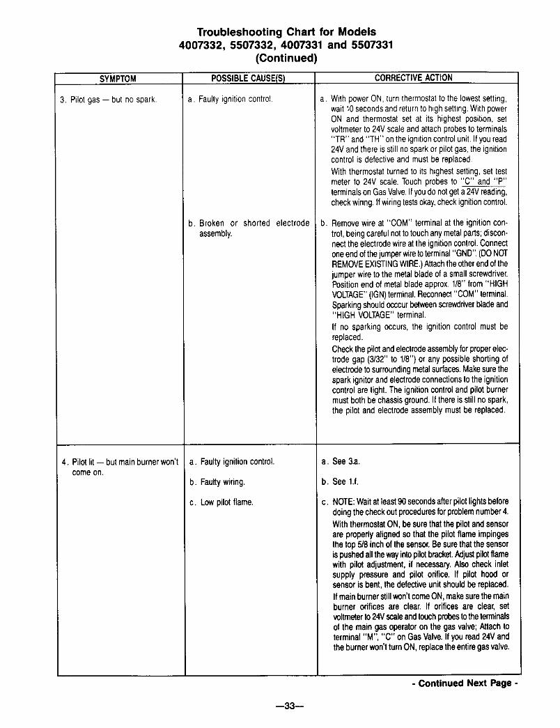
Troubleshooting Chart for Models4007332, 5507332, 4007331 and 5507331
(Continued)
SYMPTOM
3. Pilot gas-- but no spark.
4. Pilotlit-- but mainburnerwon'tcomeon.
POSSIBLECAUSE(S)
a. Faultyignitioncontrol
b. Broken or shorted electrodeassembly.
a. Faultyignitioncontrol.
b. Faultywiring.
c. Lowpilot flame.
CORRECTIVEACTION
a, WithpowerON,turnthermostatto the lowestsetting,wait10secondsandreturnto highsetting.WithpowerON and thermostatset at its highestposition, setvoltmeterto 24Vscaleandattachprobesto terminals"TR" and"TH" ontheignitioncontrolunit.Ifyouread24Vandthereis stillnosparkor pilotgas,the ignitioncontrol is defectiveand mustbe replaced.With thermostatturnedto its highestsetting,set testmeterto 24V scale.Touchprobesto "C" and "P"terminalsonGasValve.Ifyoudo notgeta 24Vreading,checkwiring,Ifwiringtestsokay,checkignitioncontrol.
b. Removewireat "COM" terminalat the ignitioncon-trol,beingcarefulnotto touchanymetalparts;discon-nectthe electrodewireattheignitioncontrol.Connectoneendofthejumperwireto terminal"GND",(DONOTREMOVEEXISTINGWIRE.)Attachtheotherendofthejumperwireto the metalbladeof a smallscrewdriver.Positionendof metalbladeapprox,1/8" from"HIGHVOLTAGE"(IGN)terminal.Reconnect"COM"terminal.Sparkingshouldocccurbetweenecrev,_lriverbladeand"HIGH VOLTAGE"terminal.
If no sparkingoccurs,the ignition controlmust bereplaced.Checkthepilotandelectrodeassemblyforprobereleotrode gap (3/32" to 1/8") or any possibleshortingofelectrodetosurroundingmetalsurfaces.Makesurethespark ignitorandelectrodeconnectionsto the ignitioncontrolaretight. The ignitioncontrolandpilot burnermustbothbechassisground.If thereis stillno spark,the pilot and electrodeassemblymust be replaced.
a. See3.a.
b. See 1.f,
C. NOTE:Waitatleast90secondsafterpilotlightsbeforedoingthecheckoutproceduresforproblemnumber4.WiththermostatON,be surethat thepilotandsensorareproperlyalignedso that the pilot flameimpingesthetop 5/8inchof thesensor.Besurethatthe sensorispushedallthewayintopilotbracket.Adjustpilotflamewith pilot adjustment,if necessary.Alsocheckinletsupply pressureand pilotorifice, If pilot hood orsensorisbent, thedefectiveunitshouldbereplaced.Ifmainburnerstillwon'tcomeON,makesurethemainburner orifices are clear. If orificesare clear, setvoltmeterto24Vscaleandtouchprobestotheterminalsof the maingas operatoron the gasvalve;Attachtoterminal"M", "C" onGasValve.If youread24',/andtheburnerwon'tturnON,replacetheentiregasvalve.
- Continued Next Page -
--33--

Troubleshooting Chart for Models4007332, 5507332, 4007331 and 5507331
SYMPTOM
4. Pilotlit -- but mainburnerwon'tcomeON(continued).
POSSIBLE CAUSE(S)
d, Improperalignment of sensor inpilot flame.
e. Faultyflamesensor.
CORRECTIVEACTION
a. Faultypilotvalve.
b. Faultywiring.
a. Lowpilot flame.
b. Improperalignmentof sensorinpilotflame.
c. Pilotflamebeingdrownawayfromsensor.
d. WhenmainburnercomesON,ensurethatpilotflameis strong,sensorisproperlyaligned,andthatpilotflameimpingesthetop5/8inchofthesensor(Seeproceduresforcheckingforproperpilotflameandalignmentinpro-blem4.c.)Checkthe pilotandelectrodeassemblyforproperelectrodegap(3/32" to 1/8") or any possibleshortingof electrodeto surroundingmetalsurfaces.Makesurethe sparkignitorandelectrodeconnectionstothe ignitioncontrolaretight.Theignitioncontrolandpilot burnermustbothbe chassisground.If thereisstill no spark,the pilotand electrodeassemblymustbe replaced.
e, BE SUREPOWERIS OFF,BEFOREPERFORMINGTHISTEST_!Settestmeterto "ohm"scaleorusecontinuitycheeke_Touchoneendofprobestotipofflamesensor,theotherto "SENS" terminalontheignitioncontrol.Ohmmetershouldread"0", continuityshouldbe evident.If youdon'tobtainareading,removewiringfromsensorandtestbothindividually.Ifcontinuityis notevident,replacewiringand/orsensor.Thereshouldbe NO continuitybetweensensorand"GND" terminalonthe ignitioncontrol.Testingwiringandsensorindividually,determinewhichis shortedonground.Replaceor repair.TurnON Power.
5. PilotcyclesOFFandONbyitself, a. See2.b.
b. See l.f.
6. Mainburnershutsdownbefore a. See4.C.thermostatis satisfied.
b. See4.d.
d. Improperheatanticipatorsetting.
e. Faultylimit.
c. WhenmainburnercomesON,ensurethatthe pilotflameisstrongandthe sensoris properlyalignedandthat the pilot flame impingesthe top 5/8 inchof thesensor.(Seeproceduresfor checkingfor properpilotflameandalignmentin problem4.d.)If thepilotflameis drawnawayfromthe sensorwhenthe mainburnercomesON,the causecouldbethemanualvalveis notin the full ON position.NOTE:Lowinletgas pressureto the gas controlcanbe causedbyseveralproblemsandis notwithinthescopeoftheproceduresoutlinedin thisserviceguide.Consultyourlocalutilityor gassupplier.
d. see 6.c.
Checkthe settingof the heatanticipatorin the wallthermostat,Setitto settingspecifiedonthegasvalve,
e. Thesystemmaybecyclingona faultylimit.Usingatestmeter,set tothe110voltscale,checkfor avoltagereadingacrossthe limitwhenthemainburnershutsOFF.If yougeta 24 voltor110voltreadingonshut-down,replacedefectivelimit.
--34---

WILLIAMS DIRECT VENT GAS-FIRED WALL FURNACE
REPAIR PARTS FOR MODELS --
4007332, 4007331, 4007732 and 4007731
CABINET and BODYASSEMBLY
%
USE ONLY MANUFACTURER'SAUTHORIZED PARTS
FOR PARTS LISTSEE PAGE 37
--35--

WILLIAMS DIRECT VENT GAS-FIRED WALL FURNACE
WILLIAMS DIRECT VENTGAS-FIRED WALL FURNACE
FOR CONTROL ASSEMBLY MODELS-4007732 & 4007731
FOR PARTS LISTSEE PAGE 38
I
USE ONLY MANUFACTURER'SAUTHORIZED PARTS
I •!
--36--
WILLIAMS DIRECT VENTGAS-FIRED WALL FURNACE
FOR CONTROL ASSEMBLY MODELS-4007332 & 4007331

WILLIAMS DIRECT VENT GAS-FIRED WALL FURNACE
REPLACEMENT PARTS LIST FOR MODELS --
4007332, 4007732, 4007331 and 4007731
REF.
NO.
1234
5
6789
10
11121314
15
1617
DESCRIPTION
Outer Casing with Air Pan
Heating ElementElement TubeInner LinerDeflector Baffle Handle
Fan Shroud
Top Trim CoverTop Front PanelCenter Front Panel
Bottom Front Panel
Element Face CoverLimit SwitchFan SwitchMotor
Motor Support (2 Req.)
Transformer
4007332
11 C42-211C6711C3711B4611C63
11B8611A4011B10211C6211B103
11A103P200300P200200P1511017B46
P024200
11A152
18 P022800
19 P200600
20 11B0521 11C6823 11A1824 P200900
25 P15190026 P103100
27 11C0928 11A0729 11B49
,_ 4701
3O31 670132
Internal Wires (Except Ignition Control Wires For Models4007332 & 4007331)
Vibration Mounts (4 Req.)Fan Blade
Switch BoxSwitch Box Cover
Peep Hole CoverElement Face Gasket
Air Pan Tunnel GasketSeal Gasket
Vent CapFlue Extension -- 9801 KitAir Inlet Extension
,it 4701 Trim Strip Kit
* Inner Boot* Outer Boot -- 6701 Side Outlet Kit 10" Boots
* Plaster Ground
6702 Side Casing Grille Kit* 6703 Diffusing Grille Kit - Two-Way* 6704 Diffusing Grille Kit - One-WayGasket, Burner Pan (2 Req.)
Owner's Manual
PART NO. FOR MODEL:
4007732 4007331
11C42-2 11C42-211C67 11C6711C37 11C3711B46 11B4611C63 11C63
11B86 11B8611A40 11A4011B102 11B10211C62 11C6211B103 11B103
11A103 11A103P200300 P200300P200200 P200200P151101 P1511017B46 7B46
P024200 P024200
11A152 11A152P022800 P022800P200600 P200600
11B05 11B0511C68 11C6812B40 11A18P200900 P200900
P151900 P151900P103100 P103100
11C09 11C0911A97 11A9711B49 11B49
4701 4701
6701
33 6702 670234 6703 6703
6704 6704
34A P321020 P321020
._ P321004 P321004
* Not available separately, in kit form onlyNOTE: Screws and bolts are standard hardware items, available locally.
Not shown. Continued
4007731
11C42-211C6711C3711B4611C63
11B8611A4011B10211C6211B103
1tA103P200300P200200F1511017B46
P024200
11A152P022800P200600
11B05
11C6812B40P200900
P151900P103100
tlC0911A9711B49
4701
6701 6701
6702 67026703 67036704 6704P321020 P321020
P321004 P321004
For paM illu_ration see page 35,
--37--

WILLIAMS DIRECT VENT GAS-FIRED WALL FURNACE
REPLACEMENT PARTS LIST FOR MODELS (Con't) --4007332, 4007732, 4007331 and 4007731
REF.NO.
353637
38
39
40
4007332
11S58P151700P090500
P025600
P026200
11C64-2
DESCRIPTION
ManifoldManifold Gasket
Orifice Fitting, Specify Model & Gas
Burner, Cast Iron, Nat. or L.P.G.
Locknut (2 Req.)
Burner Pan
Valve, Williams Nat.Valve, Williams L.P.G,Valve, Williams Nat.Valve, Williams L.P.G.
Pilot, Cast Iron Burner, L.P,G.
Pilot, Cast Iron Burner, Nat.
ThermocoupleFlame Sensor
Pilot Tube GasketPilot Tube SealGasket 44 inch
Burner Spacer, Cast Iron BurnerThermostat
Ignition Control Unit, Williams
Piezo Gas Lighter (Manual Spark Lighter)Manifold AdapterIgnition ShieldIgnition Control Wires
4007731
11B58P151700P090500
P025600
P026200
11C64-2
PART NO. FOR MODEL:
4007732 4007331
11B58 11B58P151700 P151700
P090500 P090500
P025600 P025600
P026200 P026200
11C64-2 11C04-2
P322041
-- P322044
-- P229200P229100
P254000-- P271100
P151800 P15100011A41 11A41P101600 P101600
P018100 P018100P322017 P322017-- P321910
P285500P321888 P321887-- 7C79-- 31 B036
41 m _
-- P322042P322043
42 -- P229200P229100
43 -- P254000P271100
44 P151800 P15180045 11A41 11A4146 P101600 P101600
47 P018100 P01810048 P322017 P32201749 P321910 --
50 -- P28550053 P321887 P32180854 7C79 --
31B036 --
Not available separately, in kit form only For pa_ illustration see page 36.NOTE: Screws and bolts are standard hardware items, available locally.
Not shown.
--38--

WILLIAMS DIRECT VENT GAS-FIRED WALL FURNACE
FURNACE ASSEMBLY FOR MODELS --5507332 and 5507331
CABINET and BODYASSEMBLY
I
USE ONLY MANUFACTURER'SAUTHORIZED PARTS
FOR PARTS LISTSEE PAGE 41
--39--
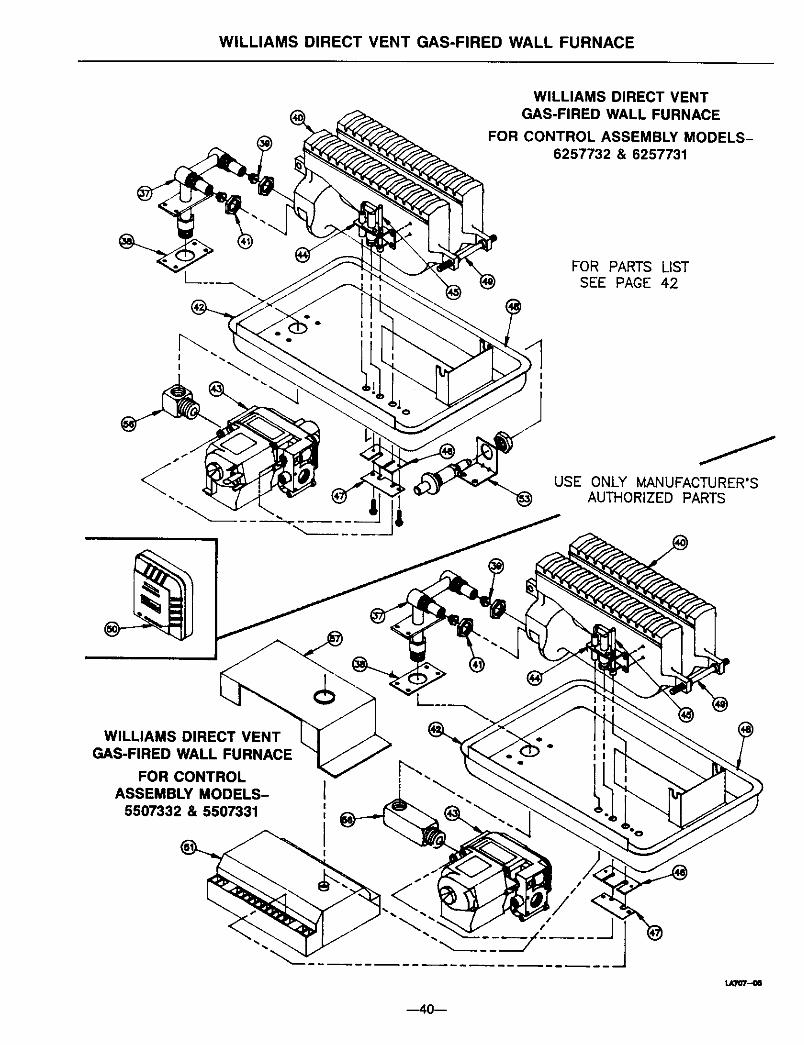
WILLIAMS DIRECT VENT GAS-FIRED WALL FURNACE
WILLIAMS DIRECT VENTGAS-FIRED WALL FURNACE
FOR CONTROL ASSEMBLY MODELS-6257732 & 6257731
FOR PARTS LISTSEE PAGE 42
USE ONLY MANUFACTURER'S"_ AUTHORIZED PARTS
WILLIAMS DIRECT VENTGAS-FIRED WALL FURNACE
FOR CONTROLASSEMBLY MODELS-
5507332 & 5507331
s I
.... J
LAI07--_
40--

WILLIAMS DIRECT VENT GAS-FIRED WALL FURNACE
REPLACEMENT PANTS LIST FOR MODELS --
5507332 and 5507331
REF.NO.
123
4
6789
10
1112131415
1617181920
212223
25262728
293031
323334
3536
36
36A
DESCRIPTION
Outer Casing with Air PanHeating ElementElement TubeInner Liner
Deflector Baffle HandleFan Shroud
Top Trim Cover
Top Front PanelCenter Front Panel
Bottom Front PanelElement Face CoverLimit SwitchSelector Switch
Fan Switch
Motor
Motor Support (2 Req.)Transformer
Internal Wires (Except ignition control wires)Vibration Mounts (4 Req,)
Fan BladeSwitch BoxSwitch Box Cover
Peep Hole CoverElement Face Gasket
Air Pan Tunnel GasketSeal Gasket
Vent CapFlue Extension -- 9801 KitAir Inlet Extension
* 4701 Trim Strip Kit
_r Inner Boot* Outer Boot* Plaster Ground
6702 Side Casing Grille Kit6703 Diffusing Grille Kit - Two-Way6704 Diffusing Grille Kit - One-Way
Gasket, Burner Pan (2 Req.)
-- 6701 Side Outlet Kit
PART NO. FOR MODEL:
5507332
11C42-1
11C6611C37
7B79
11C6311B8611A4011B102
11C59
ttB10311A103P296001P200400P200200
P0621017B46P0242007A194P022800
P20060011B0511C68
12B40P200900P151900P103106
11C0911A9711B49
4701
6701
5507331
11C42-111C6611C377B79
11C6311B8611A4011Bt0211C59
11B10311A103P296001P2OO400P200200
P0621017B46P0242007A194P022800
P20060011B0511C68
12B40P2O090OP151900P103100
11C0911A9711B49
4701
6701
6702 67026703 67036704 6704
P321020 P321020
Owner's Manual P321004 P321004
* Not available separately, in kit form only For part illustration see page 39.NOTE: Screws and bolts are standard hardware items, available locally._r Not shown. Continued
--41--
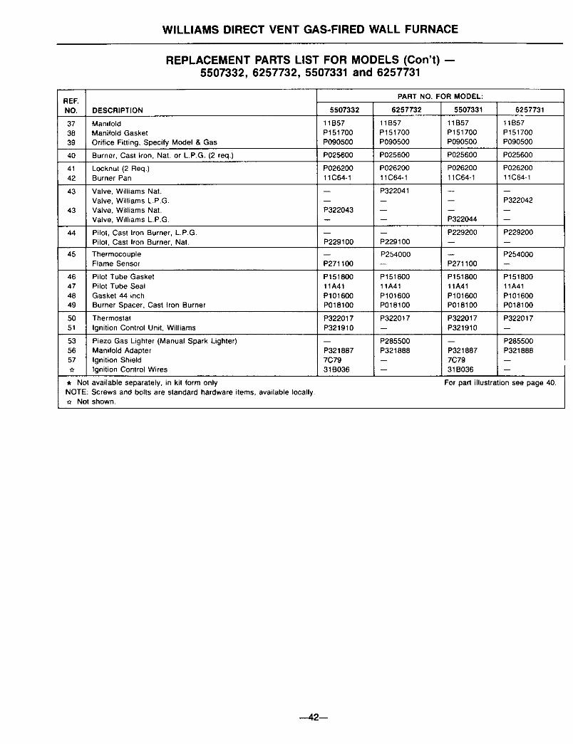
WILLIAMS DIRECT VENT GAS-FIRED WALL FURNACE
REPLACEMENT PARTS LIST FOR MODELS (Con't) --5507332, 6257732, 5507331 and 6257731
RERNO, DESCRIPTION
373839
40
4142
43
43 P322043
44P229100
45P271100
46 P15180047 11A4148 P10160049 P018100
50 P32201751 P321910
5356 P32188757 7C79
31B036
,* Not available separately, in kit form onlyNOTE: Screws and bolts are standard hardware items, available locally._r Not shown.
ManifoldManifold Gasket
Orifice Fitting, Specify Model & Gas
Burner, Cast Iron, Nat. or L.P.G, (2 req.)
Locknut (2 Req)Burner Pan
Valve, Williams Nat.Valve, Williams L.P.G.
Valve, Williams Nat.Valve, Williams L.P.G
Pilot, Cast Iron Burner, L.P.G.Pilot, Cast Iron Burner, Nat
ThermocoupleFlame Sensor
Pilot Tube GasketPilot Tube SealGasket 44 inch
Burner Spacer, Cast Iron Burner
Thermostat
Ignition Control Unit, Williams
Piezo Gas Lighter (Manual Spark Lighter)Manifold AdapterIgnition ShieldIgnition Control Wires
5507332
11B57P151700P090500
P025600
P02620011C64-1
PART NO. FOR MODEL:
6257732 5507331
11B57 t1B57P151700 P151700P090500 P090500
P025600 P025600
P026200 P02620011C64-1 11C64-1
P322041
P229100
P254000
P15180011A41P101600P018100
P322017
P285500P321688
6257731
11B57P151700P090500
P025600
P02620011C64-1
-- P322042
P322044
P229200 P229200
-- P254000P271100
P151800 P15180011A41 11A41P101600 P101600P018100 P018100
P322017 P322017P321910
-- P285500P321887 P3218667C7931B036
For pad illustr_ion see page 40.
--42--

WILLIAMS DIRECT VENT GAS-FIRED WALL FURNACE
FURNACE ASSEMBLY FOR MODELS --6257732 and 6257731
CABINET and BODYASSEMBLY
USE ONLY MANUFACTURER'SAUTHORIZED PARTS
FOR PARTS LISTSEE PAGE 44
--43--
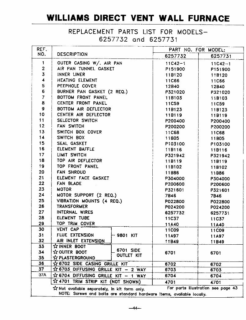
WILLIAMS DIRECT VENT WALL FURNACE
REF.NO.
1
2345678
9101112131415161718
19202122232425262728
293O
3132533435563737A
REPLACEMENT PARTS LIST FOR MODELS-6257732 and 6257731
DESCRIPTION
OUTER CASING W/. AIR PANAIR PAN TUNNEL GASKET
INNER LINER
HEATING ELEMENT
PEEPHOLE COVER
BURNER PAN GASKET (2 RE(;}.)BOTTOM FRONT PANEL
CENTER FRONT PANEL
BOTTOM AIR DEFLECTOR
PART
6257732
11C42-1
P151900
11B120
11C66
12B40
P521020
11B103
11C59
11B125CENTER AIR DEFLECTOR
SELECTOR SWITCH
FAN SWITCH
SWITCH BOX COVER
SWITCH BOX
SEAL GASKET
ELEMENT BAFFLE
LIMIT SWITCH
TOP AIR DEFLECTOR
TOP FRONT PANEL
FAN SHROUD
11Bl19
P20O40O
P200200
11C68
11B05
P105100
11Bl16
P521942
11Bl19
11B102
11B86
NO. FOR MODEL:
6257731
11C42-1
P151900
11B120
11C66
12B40
P321020
11B105
11C59
11B125
11Bl19
P200400
P200200
11C68
11B05P103100
11Bl16
P521942
11Bl19
11B102
11B86ELEMENT FACE GASKET
FAN BLADE
MOTOR
MOTOR SUPPORT (2 REQ.)
VIBRATION MOUNTS (4 REQ.)TRANSFORMER
INTERNAL WIRES
ELEMENT TUBETOP TRIM COVER
VENT CAP
FLUE EXTENSION - 9801 KIT
AIR INLET EXTENSION_" INNER BOOT_'OUTER BOOT 6701 SIDE
PLASTERGROUND OUTLET KIT
"_6702 SIDE CASING GRILLE KIT
_'6705 DIFFUSING GRILLE KIT - 2 WAY
_'6704 DIFFUSING GRILLE KIT - 1 WAY
_'4701 TRIM STRIP KIT (NOT SHOWN)
P304000
P200600
P321601
7B46
P022800
P024200
6257752
11C57
11A40
11C09
11A97
11B49
6701
6702
6705
6704
4701
_" Not available separately, in kit form only. For parts IllustrationNOTE: Screws and bolts are standard hardware Items, available locally.
P504000P200600
P321601
7B46
P022800
P024200
6257751
11C37
11A4011C09
11A9711B49
6701
6702
6703
6704
4701
see page 45
--44--
Service Record
DATE MAINTENANCE PERFORMED COMPONENTS REQUIRED
.--45 m

-- Notes --
--46--

-- Notes --
ownersmanual
SERVICE
MODEL NOS.
4007332
4007732
5507332
6257732
4007331
4007731
5507331
6257731
Service HintsIf your furnace fails to work right, you may avoid inconvenience and the costof a service call by checking the following points before you call for service.
FOR YOUR SAFETY FOR YOUR SAFETY
Do not store or use gasoline If you smell gas:or other flammable vapors and 1. Open windows.
2. Don't touch electrical.liquids in the vicinity of this or any 3. Extinguish any open flame.other appliance. 4. Immediately call your gas
supplier.
POSSIBLE CAUSE WHAT TO DO
If fan motor is noisy --Housing rattling.Fan dirty.Fan blade bent.Motor bearings need oiling.
Tighten screws.Clean fan blade.Replace fan blade.Oil motor.
If fan does not run -Fuse blown or tripped circuitbreaker.
Motor bearings need oiling.
Replace fuse or reset breaker.
Oil motor.
If burner is noisy --Pilot observation door loose or
missing. (peep hole cover)Tighten wingnut or replacedoor.
If your furnace is not heating or not giving enough heat --Replace fuse or reset breaker,Fuse blown or tripped circuit
breaker.Thermostat is not set correctly.
Air flow restricted.
Reset thermostat to desiredsetting.
Check that doors, drapes orfurniture are not blockingfurnace louvers.
If your furnace short cycles --Thermostat anticipator not set
correctly.Set anticipator (See Page 11).
If your furnace pops and cracks --Heat exchanger expansion and Normal condition, especiallycontraction, with newer furnaces.
See troubleshooting section for more detailed information.
Illustrations are representative only.Specifications are subject to change without notice.
How to Order Repair PartsWhen ordering repair parts, always give the following All parts listed herein may be ordered from your equip-information: ment supplier.1. MODELNUMBER The Model Number of your Williams wall furnace will be2. MFG.DATECODE found on the rating plate near gas valve, inside control3. PART NUMBER4. PART DESCRIPTION compartment.
WILLIAMS FURNACE COMPANY225 Acacia Street
Colton, CA 92324 USA
(909) 825-0993
MANUFACTUREDIN THE U.S.A.
Established 1916
FAX: (909) 824-8009
©1998 The Williams Furnace Company Printed in U.S.A. Rev. 12/98 P321004