Embed Size (px)
Citation preview

Owner’s ManualAir-cooled Recreational
Vehicle GeneratorsQUIETPACT® 55, 65 and 75
• Models: 004702-0, 004703-0004704-0, 004705-0004706-0, & 004707-0
This manual should remain with the unit.

Generac® Power Systems, Inc.
INTRODUCTIONREAD THIS MANUAL THOROUGHLY
If any portion of this manual is not understood, con-tact the nearest Generac Authorized Service Dealerfor starting, operating and servicing procedures.
Throughout this publication, and on tags and decals affixed to the generator, DANGER, WARNING,CAUTION and NOTE blocks are used to alert per-sonnel to special instructions about a particularoperation that may be hazardous if performed incor-rectly or carelessly. Observe them carefully. Their def-initions are as follows:
After this heading, read instructions that, if notstrictly complied with, will result in personalinjury, including death, and property damage.
After this heading, read instructions that, if notstrictly complied with, may result in personalinjury or property damage.
After this heading, read instructions that, if notstrictly complied with, could result in damage toequipment and/or property.
NOTE:
After this heading, read explanatory statementsthat require special emphasis.
These safety warnings cannot eliminate the hazardsthat they indicate. Common sense and strict compli-ance with the special instructions while performingthe service are essential to preventing accidents.
Four commonly used safety symbols accompany theDanger, Warning and Caution blocks. The type ofinformation each indicates follows:
This symbol points out important safety infor-mation that, if not followed, could endangerpersonal safety and/or property of others.
This symbol points out potential explosion hazard.
This symbol points out potential fire hazard.
This symbol points out potential electricalshock hazard.
The operator (driver) is responsible for proper andsafe use of the vehicle and its equipment, and thesafety of all vehicle occupants. We strongly recom-mend that the operator read this manual and thor-oughly understand all instructions before using thisequipment. We also strongly recommend instructingother occupants in the vehicle to properly start andoperate the generator. This prepares them if theyneed to operate the equipment in an emergency.
CONTENTSThis manual contains pertinent owner’s information,including warranty, electrical diagrams, explodedviews and lists of repair parts for generator modelnumbers 004702-0, 004703-0, 004704-0, 004705-0,004706-0, and 004707-0. In addition, the latter por-tion of this manual contains information necessaryfor the proper installation of these generators.
OPERATION AND MAINTENANCEIt is the operator's responsibility to perform all safe-ty checks, to make sure that all maintenance for safeoperation is performed promptly, and to have theequipment checked periodically by a GeneracAuthorized Service Dealer. Normal maintenance ser-vice and replacement of parts are the responsibility ofthe owner/operator and, as such, are not considereddefects in materials or workmanship within theterms of the warranty. Individual operating habitsand usage contribute to the need for maintenanceservice.
Proper maintenance and care of the generatorensures a minimum number of problems and keepoperating expenses at a minimum. See a GeneracAuthorized Service Dealer for service aids and acces-sories.
HOW TO OBTAIN SERVICEWhen the generator requires servicing or repairs,simply contact a Generac Authorized Service Dealerfor assistance. Service technicians are factory-trainedand are capable of handling all service needs.
When contacting a Generac Authorized ServiceDealer or the factory about parts and service, alwayssupply the complete model number and serial num-ber of the unit as given on its data decal, which islocated on the generator.
Model No. ____________ Serial No. ______________
◆
◆
◆
!
DANGER
◆
AUTHORIZED SERVICEDEALER LOCATION
To locate the nearest GENERAC AUTHORIZEDSERVICE DEALER, please call this number:
1-800-333-1322ONLY DEALER LOCATION INFORMATION
CAN BE OBTAINED AT THIS NUMBER; or locate us on the web at
www.generac.com.
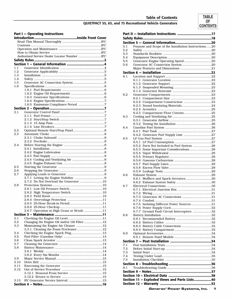
Table of ContentsQUIETPACT 55, 65, and 75 Recreational Vehicle Generators
Generac® Power Systems, Inc. 1
Part I — Operating InstructionsIntroduction ..................................................Inside Front Cover
Read This Manual Thoroughly ..........................................IFCContents ............................................................................IFCOperation and Maintenance ..............................................IFCHow to Obtain Service ......................................................IFCAuthorized Service Dealer Locator Number ..........................IFC
Safety Rules ..................................................................................2Section 1 – General Information ............................................41.1 Generator Identification ................................................41.2 Generator Applicability ..................................................51.3 Installation ....................................................................51.4 Safety ............................................................................51.5 Generator AC Connection System..................................51.6 Specifications ................................................................6
1.6.1 Fuel Requirements ..............................................61.6.2 Engine Oil Requirements ....................................61.6.3 Generator Specifications......................................61.6.4 Engine Specifications ..........................................71.6.5 Emissions Compliance Period ............................7
Section 2 – Operation ................................................................72.1 Generator Control Panel ................................................7
2.1.1 Fuel Primer..........................................................72.1.2 Start/Stop Switch ................................................72.1.3 15 Amp Fuse........................................................72.1.4 Line Breakers ......................................................7
2.2 Optional Remote Start/Stop Panel..................................82.3 Automatic Choke ..........................................................8
2.3.1 Choke Solenoid ..................................................82.3.2 Prechoke..............................................................8
2.4 Before Starting the Engine ............................................82.4.1 Installation..............................................................82.4.2 Engine Lubrication ................................................82.4.3 Fuel Supply ............................................................82.4.4 Cooling and Ventilating Air ....................................82.4.5 Engine Exhaust Gas ..............................................8
2.5 Starting the Generator ..................................................92.6 Stopping the Generator..................................................92.7 Applying Loads to Generator ........................................9
2.7.1 Letting the Engine Stabilize ................................92.7.2 Do Not Overload the Generator ........................10
2.8 Protection Systems ......................................................102.8.1 Low Oil Pressure Switch....................................102.8.2 High Temperature Switch ..................................102.8.3 Field Boost ........................................................102.8.4 Overvoltage Protection ......................................112.8.5 25-Hour Break-in Period....................................112.8.6 25-Hour Checkup ..............................................112.8.7 Operation in High Grass or Brush ....................11
Section 3 – Maintenance ........................................................113.1 Checking the Engine Oil Level......................................113.2 Changing the Engine Oil and/or Oil Filter ....................123.3 Maintaining the Engine Air Cleaner ............................12
3.3.1 Cleaning the Foam Precleaner............................123.4 Checking the Engine Spark Plug..................................133.5 Fuel Filter (Gasoline Only) ..........................................133.6 Clean Spark Arrestor ..................................................133.7 Cleaning the Generator ................................................143.8 Battery Maintenance ....................................................14
3.8.1 Weekly ..............................................................143.8.2 Every Six Months ..............................................14
3.9 Major Service Manual ..................................................153.10 Drive Belt ....................................................................153.11 Exercising the Generator ............................................153.12 Out of Service Procedure ............................................15
3.12.1 Removal From Service ....................................153.12.2 Return to Service ............................................15
3.13 RV Generator Service Interval......................................15Section 4 – Notes......................................................................16
Part II — Installation Instructions ........................................17Safety Rules................................................................................18Section 5 — General Information..........................................205.1 Purpose and Scope of the Installation Instructions......205.2 Safety ..........................................................................205.3 Standards Booklets ....................................................205.4 Equipment Description................................................205.5 Generator Engine Operating Speed..............................205.6 Generator AC Connection System................................20
Major Features and Dimensions ..................................21Section 6 — Installation ..........................................................226.1 Location and Support ..................................................22
6.1.1 Generator Location............................................226.1.2 Generator Support ............................................226.1.3 Suspended Mounting ........................................236.1.4 Generator Restraint ..........................................23
6.2 Generator Compartments ............................................236.2.1 Compartment Size ............................................236.2.2 Compartment Construction ..............................236.2.3 Sound Insulating Materials................................246.2.4 Acoustics ..........................................................256.2.5 Compartment Floor Cutouts..............................25
6.3 Cooling and Ventilating Air ..........................................256.3.1 Generator Airflow ..............................................256.3.2 Testing the Installation ......................................26
6.4 Gasoline Fuel System ..................................................266.4.1 Fuel Tank ..........................................................276.4.2 Generator Fuel Supply Line ..............................27
6.5 LP Gas Fuel System ....................................................276.5.1 LP Fuel Consumption ........................................276.5.2 Parts Not Included in Fuel System ....................286.5.3 Some Important Considerations........................286.5.4 Vapor Withdrawal ..............................................286.5.5 Primary Regulator..............................................286.5.6 Gaseous Carburetion ........................................286.5.7 Fuel Supply Lines ..............................................296.5.8 Excess Flow Valve ..............................................296.5.9 Leakage Tests ....................................................29
6.6 Exhaust System ..........................................................296.6.1 Mufflers and Spark Arrestors............................306.6.2 Exhaust System Safety ......................................30
6.7 Electrical Connections ................................................306.7.1 Electrical Junction Box ....................................316.7.2 Wiring ................................................................316.7.3 Generator AC Connections ................................316.7.4 Conduit..............................................................316.7.5 Isolating Different Power Sources ......................316.7.6 Power Supply Cord............................................326.7.7 Ground Fault Circuit Interrupters ....................32
6.8 Battery Installation ......................................................326.8.1 Recommended Battery ......................................326.8.2 Battery Cables ..................................................326.8.3 Battery Cable Connections ................................326.8.4 Battery Compartment ........................................32
6.9 Optional Accessories....................................................346.9.1 Remote Panel Models ........................................34
Section 7 — Post Installation ................................................347.1 Post Installation Tests ..................................................347.2 Before Initial Start-up ..................................................347.3 Initial Start ..................................................................347.4 Testing Under Load......................................................357.5 Installation Checklist ..................................................35Section 8 – Troubleshooting ..................................................368.1 Troubleshooting Guide ................................................36Section 9 – Notes......................................................................37Section 10 – Electrical Data ..................................................38Section 11 – Exploded Views and Parts Lists....................40Section 12 – Warranty ............................................................52
2 Generac® Power Systems, Inc.
Study these SAFETY RULES carefully beforeinstalling, operating or servicing this equipment.Become familiar with this manual and with the unit.The generator can operate safely, efficiently and reli-ably only if it is properly installed, operated andmaintained. Many accidents are caused by failing tofollow simple and fundamental rules or precautions.
Generac cannot possibly anticipate every possible circumstance that might involve a hazard. The warn-ings in this manual, and on tags and decals affixed to the unit, are, therefore, not all-inclusive. Ifusing a procedure, work method or operating tech-nique Generac does not specifically recommend,ensure that it is safe for others. Also make sure theprocedure, work method or operating technique thatchosen does not render the generator unsafe.
Despite the safe design of this generator, operating this equipment imprudently, neglect-ing its maintenance or being careless can cause possible injury or death. Permit only responsi-ble and capable persons to operate or maintainthis equipment.
Potentially lethal voltages are generated bythese machines. Ensure all steps are taken torender the machine safe before attempting towork on the generator.
Parts of the generator are rotating and/or hotduring operation. Exercise care near runninggenerators.
GENERAL HAZARDS
• For safety reasons, Generac recommends that the installation, initial start-up and mainte-nance of this equipment is carried out by aGenerac Authorized Service Dealer.
• The generator engine releases DEADLY carbonmonoxide gas through its exhaust system. Thisdangerous gas, if breathed in sufficient concentra-tions, can cause unconsciousness or even death.Never operate the generator set with the vehicleinside any garage or other enclosed area. DO NOTOPERATE THE GENERATOR IF THE EXHAUSTSYSTEM IS LEAKING OR HAS BEEN DAMAGED.SYMPTOMS OF CARBON MONOXIDE POISON-ING ARE (a) inability to think coherently, (b) nau-sea, (c) vomiting, (d) twitching muscles, (e) throb-bing temples, (f) dizziness, (g) headaches, (h)weakness, and (i) sleepiness. IF EXPERIENCINGANY OF THESE SYMPTOMS, MOVE INTO FRESHAIR IMMEDIATELY. IF SYMPTOMS PERSIST, GETMEDICAL HELP. Shut down the generator and donot operate it until it has been inspected andrepaired.
• Never sleep in the vehicle while the genset is run-ning unless the vehicle has a working carbonmonoxide detector. The exhaust system must beinstalled in accordance with the genset installationmanual. Make sure there is ample fresh air whenoperating the genset in a confined area.
• Keep hands, feet, clothing, etc., away from drivebelts, fans, and other moving or hot parts. Neverremove any drive belt or fan guard while the unit isoperating.
• Adequate, unobstructed flow of cooling and venti-lating air is critical to correct generator operationand is required to expel toxic fumes and fuelvapors from the generator compartment. Withoutsufficient cooling airflow, the engine/generatorquickly overheats, which causes serious damage tothe generator. Do not alter the installation or per-mit even partial blockage of ventilation provisions,as this can seriously affect safe operation of thegenerator.
• When working on this equipment, remain alert atall times. Never work on the equipment whenphysically or mentally fatigued.
• Inspect the generator regularly, and contact thenearest Generac Authorized Service Dealer imme-diately for parts needing repair or replacement.
!!
!
!
DANGER
Safety RulesQUIETPACT 55, 65, and 75 Recreational Vehicle Generators
SAVE THESE INSTRUCTIONS – The manufacturer suggests that these rules for safe operation be copied and posted in potential hazard areas of the recreational vehicle. Safety should be stressed to all operators and potential operators of this equipment.! !
The engine exhaust from this productcontains chemicals known to the state
of California to cause cancer, birthdefects or other reproductive harm.
WARNING:! !
This product contains or emits chemicalsknown to the state of California to cause
cancer, birth defects or other reproductive harm.
WARNING:! !
Generac® Power Systems, Inc. 3
• Before performing any maintenance on the genera-tor, disconnect its battery cables to prevent acci-dental start up. Disconnect the cable from the bat-tery post indicated by a NEGATIVE, NEG or (–)first. Reconnect that cable last.
• Never use the generator or any of its parts as astep. Stepping on the unit can stress and breakparts, and may result in dangerous operating con-ditions from leaking exhaust gases, fuel leakage,oil leakage, etc.
ELECTRICAL HAZARDS• The generator covered by this manual produces
dangerous electrical voltages and can cause fatalelectrical shock. Avoid contact with bare wires, ter-minals, connections, etc., while the unit is running.Ensure all appropriate covers, guards and barriersare in place before operating the generator. If workmust be done around an operating unit, stand onan insulated, dry surface to reduce shock hazard.
• Do not handle any kind of electrical device whilestanding in water, while barefoot, or while handsor feet are wet. DANGEROUS ELECTRICALSHOCK MAY RESULT.
• During installation onto the vehicle, have the gen-erator properly grounded (bonded) either by solidmounting to the vehicle frame or chassis, or bymeans of an approved bonding conductor. DONOT disconnect the bonding conductor, if soequipped. DO NOT reconnect the bonding conduc-tor to any generator part that might be removed ordisassembled during routine maintenance. If thegrounding conductor must be replaced, use only aflexible conductor that is of No. 8 American WireGauge (AWG) copper wire minimum.
• In case of accident caused by electric shock, imme-diately shut down the source of electrical power. Ifthis is not possible, attempt to free the victim fromthe live conductor. AVOID DIRECT CONTACTWITH THE VICTIM. Use a nonconducting imple-ment, such as a rope or board, to free the victimfrom the live conductor. If the victim is uncon-scious, apply first aid and get immediate medicalhelp.
• Never wear jewelry when working on this equip-ment. Jewelry can conduct electricity resulting inelectric shock, or may get caught in moving com-ponents causing injury.
FIRE HAZARDS
• For fire safety, the generator must be installed andmaintained properly. Installation always mustcomply with applicable codes, standards, laws andregulations. Adhere strictly to local, state andnational electrical and building codes. Complywith regulations the Occupational Safety andHealth Administration (OSHA) has established.Also, ensure that the generator is installed inaccordance with the manufacturer’s instructionsand recommendations. Following proper installa-tion, do nothing that might alter a safe installationand render the unit in noncompliance with theaforementioned codes, standards, laws and regu-lations.
• Keep a fire extinguisher in the vehicle at all times.Extinguishers rated “ABC” by the National FireProtection Association are appropriate for use onthe recreational vehicle generator electrical sys-tem. Keep the extinguisher properly charged andbe familiar with its use. If there are any questionspertaining to fire extinguishers, consult the localfire department.
EXPLOSION HAZARDS• Do not smoke around the generator. Wipe up any
fuel or oil spills immediately. Ensure that no com-bustible materials are left in the generator com-partment, or on or near the generator, as FIRE orEXPLOSION may result. Keep the area surround-ing the generator clean and free from debris.
• Gasoline is extremely FLAMMABLE and its vaporsare EXPLOSIVE. Do not permit smoking, openflame, sparks or any source of heat in the vicinitywhile handling gasoline. Comply with all laws gov-erning the storage and handling of gasoline.
• This generator may use liquid propane (LP) gas asa fuel. LP gas is highly EXPLOSIVE. The gas isheavier than air and tends to settle in low areaswhere even the slightest spark can ignite the gasand cause an explosion.
Safety RulesQUIETPACT 55, 65, and 75 Recreational Vehicle Generators

4 Generac® Power Systems, Inc.
Section 1 – General InformationQUIETPACT 55, 65, and 75 Recreational Vehicle Generators
Please record the following information from the generator DATA DECAL or information decal.
1. Model Number ____________________ 2. Serial Number __________________
3. kW Rating__________________________ 4. Rated Voltage __________________
5. Phase ______________________________ 6. Hertz __________________________
7
9, 18
6
STARTING,DO NOT PRESS START BUTTON LONGER THEN 15 SECONDS PER ATTEMPT.
(SAE VISCOSITY)
1.8L/1.9QT
HOURS. (OR ANNUALLY)
SAE 30 OR 10W-30
5W-30 OR 5W-20
CHANGE EVERY 100
EVERY 250 HOURS.REPLACE ELEMENT
EVERY 100 HOURS.CLEAN PREFILTER
TEMPERATURE:
40˚F AND HIGHER
WITH FILTER:OIL CAPACITY
OIL & OIL FILTER:
*
AIR FILTER:
*
*
*
P A N E L
087769
072347
17 13 12 1
11, 15 (Behind Access Panel)
105
2
3
4
14
8
16
19
1.1 GENERATOR IDENTIFICATION
REFERENCE NUMBER IDENTIFICATION
1. Generator Air Intake Screen2. Data Plate3. Engine Start/Stop Switch4. 7.5 amp Fuse5. Circuit Breaker6. Optional Remote Panel Receptacle7. Generator AC Output Leads8. Starter Contactor9. Fuel Inlet10. Fuel Primer Switch
11. Fuel Pump (Behind access panel.)12. Oil Filter13. Oil Drain Plug14. Oil Dipstick and Filler Tube15. Air Filter (Behind access panel.)16. Spark Plugs17. Exhaust Outlet18. Fuel Filter19. LP Fuel Inlet
Generac® Power Systems, Inc. 5
Section 1 – General InformationQUIETPACT 55, 65, and 75 Recreational Vehicle Generators
1.2 GENERATOR APPLICABILITYThese generators have been designed and manufac-tured for supplying electrical power for recreationalvehicles. DO NOT modify the generator or use it forany application other than for what it was designed.If there are any questions pertaining to its applica-tion, write or call the factory. Do not use the unit untiladvised by competent authority.
For fire safety, the generator must have beenproperly installed in compliance with ANSI119.2-1975/NFPA 501C-1974, “Standard forRecreational Vehicles, Part III – Installation ofElectrical Systems.” The generator also musthave been installed in strict compliance withthe manufacturer’s detailed installation instruc-tions. After installation, do nothing that mightrender the unit in noncompliance with suchcodes, standards and instructions.
Use the generator set to supply electrical power foroperating one of the following electrical loads:
• QUIETPACT 55G & LP: 120 and/or 240 volts, sin-gle phase, 60 Hz electrical loads. These loads canrequire up to 5500 watts (5.5 kW) of total power,but cannot exceed 45.8 AC amperes of current at120 volts or exceed 22.9 AC amperes at 240 volts.
• QUIETPACT 65G & LP: 120 and/or 240 volts, sin-gle phase, 60 Hz electrical loads. These loads canrequire up to 6500 watts (6.5 kW) of total power,but cannot exceed 54.1 AC amperes of current at120 volts or exceed 27 AC amperes at 240 volts.
• QUIETPACT 75G & LP: 120 and/or 240 volts, sin-gle phase, 60 Hz electrical loads. These loads canrequire up to 7500 watts (7.5 kW) of total power,but cannot exceed 62.5 AC amperes of current at120 volts or exceed 31.2 AC amperes at 240 volts.
Do not overload the generator. Some installa-tions may require that electrical loads be alter-nated to avoid overloading. Applying exces-sively high electrical loads may damage thegenerator and may shorten its life. Add up therated watts of all electrical lighting, appliance,tool and motor loads the generator will powerat one time. This total should not be greaterthan the wattage capacity of the generator. Ifan electrical device nameplate gives only voltsand amps, multiply volts times amps to obtainwatts (volts x amps = watts). Some electricmotors require more watts of power (or ampsof current) for starting than for continuousoperation.
1.3 INSTALLATIONThis Owner’s Manual has been prepared under theassumption that a competent, qualified technicianinstalled the generator into a recreational vehicle. Wealso assume the installer complied with all applicablecodes, standards and regulations pertaining to instal-lation.
An INSTALLATION MANUAL was shipped with thegenerator. That Manual contains manufacturer’sinstructions and recommendations for installing theunit into an industrial vehicle. After installation,installers should forward the Installation Manual toOwners/Operators for their information.
Owners/Operators have the responsibility to makesure that nothing is done that might render the instal-lation unsafe or in non-compliance with applicablecodes, standards and instructions.
1.4 SAFETYBefore using the generator set, carefully read GEN-ERAL SAFETY RULES inside the cover. Comply withthese RULES to prevent accidents and damage toequipment and/or property. Generac suggests copy-ing and posting the GENERAL SAFETY RULES topotential operators of this equipment.
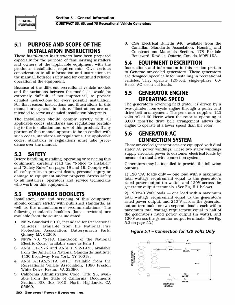
1.5 GENERATOR AC CONNECTIONSYSTEM
These air-cooled generator sets are equipped withdual stator AC power windings. These two statorwindings supply electrical power to customer electri-cal loads by means of a dual 2-wire connection sys-tem.
Generators may be installed to provide the followingoutputs:
1. 120 VAC loads only — one load with a maximumtotal wattage requirement equal to the generator’srated power output (in watts), and 120V acrossthe generator output terminals. Figure 1.1, page6, shows the generator lead wire connections for120VAC ONLY.
2. 120/240 VAC loads — one load with a maximumtotal wattage requirement equal to the generator’srated power output, and 240V across the genera-tor output terminals; or two seperate loads, eachwith a maximum total wattage requirement equalto half of the generator’s rated power output (inwatts), and 120V across the generator output ter-minals. Figure 1.2, page 6, shows the generatorlead wire connections for 120/240 VAC loads.Also refer to section 2.1.4 Line Breakers for cir-cuit breaker ratings.
This procedure should be done by a GeneracAuthorized Service Dealer or other qualified installer.
!
DANGER

6 Generac® Power Systems, Inc.
Section 1 – General InformationQUIETPACT 55, 65, and 75 Recreational Vehicle Generators
Figure 1.1 – Connection for 120 Volts Only
Figure 1.2 - Connection for 120/240 Volts
1.6 SPECIFICATIONS1.6.1 FUEL REQUIREMENTS (GASOLINE)
This generator is equipped with a gasoline fuel systemas standard equipment. Specific installations may pro-vide either a separate fuel tank for the generator, or thegenerator may “share” the vehicle engine’s fuel tank.
1.6.1.1 Fuel Consumption (gph)
NOTESome installations using a “shared” fuel tank mayhave a generator fuel pickup tube that is shorterthan the vehicle engine’s pickup tube. Such anarrangement causes the generator engine to “runout of gas” while adequate fuel for the vehicleremains in the tank.To reduce lead and carbon deposits use high qualityUNLEADED gasoline with the generator. LeadedREGULAR grade gasoline is an acceptable substitute.
NOTE:Using unleaded gasoline contributes to longer enginevalve life by reducing lead and carbon deposits.
Generac does not recommend using any gasoline containing alcohol (such as “gasohol”).If using any gasoline containing alcohol, it mustnot contain more than 10 percent ethanol, andit must be removed from the generator duringstorage. Do NOT use any gasoline containingmethanol. If using gasoline with alcohol,inspect more frequently for fuel leaks andother abnormalities.
1.6.2 ENGINE OIL REQUIREMENTSUse only high quality detergent oil rated withAmerican Petroleum Institued (API) Classification SF,SG, SH or SJ. The recommended oil viscosity weightsinclude the following:• During summer months (40 deg. F and higher),
SAE 30 or SAE 10W-30• During winter months (40 deg. F to -20 deg. F),
SAE 5W-30 or SAE5W20• DO NOT USE SAE 10W-40
◆
!
✧
◆
T1RED
T2WHITE
T3BLACK
GROUNDED NEUTRALSTATOR WINDINGS
CB1
CB2
◆ 1.6.3 GENERATOR SPECIFICATIONSSERIES QP55G QP55LP QP65G QP65LP QP75G QP75LPRotor RPM 3600 3600 3600 3600 3600 3600Rotor Poles 2 2 2 2 2 2Engine RPM 2200 2200 2571 2571 2571 2571Rated Max. Continuous AC Output Watts* 5500 5500 6500 6500 7500 7500Voltage* 120 120 120 120 120 120Rated Max. Continuous Current Amps (240V) 45.8 (22.9) 45.8 (22.9) 54.1 (27.0) 54.1 (27.0) 62.5 (31.2) 62.5 (31.2)Phase 1 1 1 1 1 1Frequency 60 Hertz 60 Hertz 60 Hertz 60 Hertz 60 Hertz 60 HertzBattery Charging Current (Max.) 2 amps 2 amps 2 amps 2 amps 2 amps 2 ampsWeight 326 lbs. 329 lbs. 328 lbs. 331 lbs. 330 lbs. 333 lbs.Length 33.7 in. 33.7 in. 33.7 in. 33.7 in. 33.7 in. 33.7 in.Width 22.2 in. 22.2 in. 22.2 in. 22.2 in. 22.2 in. 22.2 in.Height 19.6 in. 19.6 in. 19.6 in. 19.6 in. 19.6 in. 19.6 in.
* All units are reconnectable to 120 and/or 240 volts, dual voltage output. Units are not listed per RVIA/ANSI when reconnected for dual voltage output
Model 10% Load 50% Load 100% LoadQuietPact 55G 0.51 0.73 0.97QuietPact 65G 0.51 0.76 1.07QuietPact 75G 0.51 0.80 1.28

Generac® Power Systems, Inc. 7
Section 2 – OperationQUIETPACT 55, 65, and 75 Recreational Vehicle Generators
Crankcase and oil filter capacity is approximately 1.8L or 1.9 U.S. quarts. DO NOT use special additives.See Sections 3.1 and 3.2 for oil level check and fillingprocedures.
1.6.4 ENGINE SPECIFICATIONSType of EngineQUIETPACT 55/65/75 ................................................GT-760
Cooling Method ........................................................Air-cooledRated HorsepowerQUIETPACT 55..............................................27 at 3600 rpmQUIETPACT 65..............................................27 at 3600 rpmQUIETPACT 75..............................................27 at 3600 rpm
DisplacementQUIETPACT 55/65/75....................................................760cc
Compression Ratio........................................................8.6 to 1Cylinder Block ..........................Aluminum w/Cast Iron SleeveType of Governor ..............................Mechanical, Fixed SpeedEngine Governor SpeedQUIETPACT 55 ......................................................2200 rpmQUIETPACT 65/75..................................................2571 rpm
Air Cleaner ........................Paper Element w/Foam PrecleanerStarter ........................................................12-volt DC ElectricIgnition System ......................Solid-state w/Flywheel MagnetoRecommended Spark PlugChampion ..................................................................RC14YCAC....................................................................................R45SFram Autolite ......................................................................65
Spark Plug Gap........................................0.030 inch (0.8 mm)Recommended Min. Battery ............400 Cold Cranking Amps
1.6.5 EMISSIONS COMPLIANCE PERIODFor nonhandled engines the Emissions CompliancePeriod referred to on the Emissions ComplianceLabel indicates the number of operating hours forwhich the engine has been shown to meet Federalemission requirements.
• For engines less than 225 cc displacement,Category C=125 hours, B=250 hours, and A=500hours.
• For engines of 225 cc or more, Category C=250hours, B=500 hours, and A=1000 hours.
2.1 GENERATOR CONTROL PANELThe following features are mounted on the generatorcontrol panel (Figure 2.1):
2.1.1 FUEL PRIMERBefore starting a cold engine (if it has not been start-ed in more than two weeks), press this switch forapproximately ten seconds to bring fuel from thetank to the fuel pump. This rocker type switchsprings back into its original position when it isreleased.
2.1.2 START/STOP SWITCHTo crank and start the engine, hold this switch in theSTART position. Release the switch when the enginestarts. To stop an operating engine, press and holdthe switch in the STOP position until the engine shutsoff. The switch center position is the RUN position.
2.1.3 7.5 AMP FUSEThe fuse protects the engine’s DC control circuitagainst electrical overload. If the fuse element hasmelted open due to overloading, the engine cannot becranked. If the fuse must be replaced, use only anidentical 7.5 amp replacement fuse.
2.1.4 LINE BREAKERSProtects generator’s AC output circiut against overload, i.e., prevents unit from exceedingwattage/amperage capacity. The circuit breaker rat-ings are as follows:
NOTE:
If this generator has been reconnected for dualvoltage AC output (120/240 volts), install linebreakers having an amperage rating that is differ-ent than that stated above. The replacement linebreakers consist of two separate breakers with aconnecting piece between the breaker handles (sothat both breakers will operate at the same time).If the unit is reconnected for dual voltage, it is nolonger RVIA or CSA listed.
Figure 2.1 – Typical Control Panel
P R IM ES T O P
S T A R T F U E LF S E7 .5 A
0E05
80 R
EV
. B
CONTROL CENTER
C IR U ITB R E A K E R
B R A K E RC IR U IT
PRESS PRIME SWITCH FOR 10 SECONDSBEFORE STARTING. WHEN STARTING, DO NOT PRESS
START BUTTON LONGER THEN 15 SECONDS PER ATTEMPT.
IF GENERATOR DOES NOT START.REMOVE AND INSPECT FUSE.
(SEE OWNER'S MANUAL TROUBLE SHOOTING GUIDE.)
◆
◆
◆
◆
◆
◆
Model Circuit Breaker 1 Circuit Breaker 2 240 VoltQuietPact 55 30A 20A 25A 2PQuietPact 65 30A 30A 30A 2PQuietPact 75 35A 35A 35A 2P

8 Generac® Power Systems, Inc.
Section 2 – OperationQUIETPACT 55, 65, and 75 Recreational Vehicle Generators
2.2 OPTIONAL REMOTESTART/STOP PANEL
A remote mounted Start/Stop Panel (Figure 2.2) isavailable that allows starting and stopping the gener-ator engine conveniently from inside the vehicle. Theremote panel includes a Start/Stop switch, hourme-ter, generator run lamp, a fuel prime switch, and awire harness.
Figure 2.2 — Optional Remote Panel(Part Numbers 0F0429 and 0F0430)
2.3 AUTOMATIC CHOKEThis engine is equipped with an automatic choke thatconsists of two main components: a choke solenoidand prechoke.
2.3.1 CHOKE SOLENOIDDuring engine cranking (Start/Stop switch atSTART), a solid-state choke module signals thechoke solenoid to activate and cycle (choke on/chokeoff) until the engine starts. The choke solenoid thusopens and closes the carburetor choke valve onlywhen the engine is cranking. When the engine starts,the choke stops cycling.
2.3.2 PRECHOKEThe choke system also has a temperature-sensitivemetal strip that adjusts choke valve angle accordingto ambient temperatures (i.e., in cold ambient tem-peratures, choke valve closes more). Once the enginestarts, an element heats the temperature-sensitivestrip to a normal operating condition, opening thechoke valve. This may take about three minutes incooler weather.
2.4 BEFORE STARTING THE ENGINENOTE:
Instructions and information in this manualassume the generator has been properly installed,connected, serviced, tested and adjusted by aqualified installation technician or installationcontractor.
2.4.1 INSTALLATIONGenerator installation must have been properly com-pleted so it complies with all applicable codes, stan-dards and regulations and with the manufacturer'srecommendations.
2.4.2 ENGINE LUBRICATIONHave the engine crankcase properly serviced with therecommended oil before starting. Refer to Section1.6.3 and Sections 3.1 and 3.2 for oil servicing pro-cedures and recommendations.
Any attempt to crank or start the engine beforeit has been properly serviced it with the recom-mended oil may result in an engine failure.
2.4.3 FUEL SUPPLYThe engine must have an adequate supply of properfuel to operate. Before starting it, check that sufficientfuel is available.
NOTE:
Depending on the installation, the generator mayhave either a separate fuel tank, or it may “share”the vehicle engine’s fuel tank.
2.4.4 COOLING AND VENTILATING AIRAir inlet and outlet openings in the generator com-partment must be open and unobstructed for contin-ued proper operation. Without sufficient cooling andventilating airflow, the engine/generator quickly over-heats, which causes it to shut down and may damagethe generator.
2.4.5 ENGINE EXHAUST GASBefore starting the generator engine, be sure there isno way for exhaust gases to enter the vehicle interiorand endanger people or animals. Close windows,doors and other openings in the vehicle that, if open,might permit exhaust gases to enter the vehicle.
◆
◆
◆
!
◆
◆
◆
◆
PRIME
FUEL
STOP
RUN

Generac® Power Systems, Inc. 9
Section 2 – OperationQUIETPACT 55, 65, and 75 Recreational Vehicle Generators
The generator engine releases DEADLY carbonmonoxide gas through its exhaust system. Thisdangerous gas, if breathed in sufficient concen-trations, can cause unconsciousness or evendeath. Never operate the generator set withthe vehicle inside any garage or other enclosedarea. DO NOT OPERATE THE GENERATOR IF THEEXHAUST SYSTEM IS LEAKING OR HAS BEENDAMAGED. SYMPTOMS OF CARBON MONOX-IDE POISONING ARE (a) inability to think coher-ently, (b) nausea, (c) vomiting, (d) twitchingmuscles, (e) throbbing temples, (f) dizziness, (g)headaches, (h) weakness, and (i) sleepiness. IFEXPERIENCING ANY OF THESE SYMPTOMS,MOVE INTO FRESH AIR IMMEDIATELY. IF SYMP-TOMS PERSIST, GET MEDICAL HELP. Shut downthe generator and do not operate it until it hasbeen inspected and repaired.
Never sleep in the vehicle while the genset isrunning unless the vehicle has a working carbonmonoxide detector. The exhaust system must beinstalled in accordance with the genset installa-tion manual. Make sure there is ample fresh airwhen operating the genset in a confined area.
2.5 STARTING THE GENERATORNOTE:
Read the vehicle manufacturer’s instructions. Theowner/operator should become familiar with thevehicle in which this generator is installed.Differences exist between vehicles. For example,some vehicles may use a transfer switch to isolatedockside power from the generator, while othervehicles may use an isolating receptacle. Somevehicles may be equipped with a DC converterwhich allows the generator to power certain DClighting and other DC loads.
To crank and start the generator engine, proceed asfollows:
1. Turn OFF electrical loads using the means pro-vided in the vehicle (such as a main line circuitbreaker or transfer switch).
NOTE:
If starting from the generator control panel, turnOFF loads by setting the generator’s main circuitbreaker to the OFF (or open) position. If startingfrom a remote panel, turn OFF loads using themeans provided in the vehicle (such as a main cir-cuit breaker). Electrical load circuits will beturned ON after the generator has started, stabi-lized and warmed up.
2. If the engine has not been started in more thantwo weeks, press the Fuel Pump Primer switchand hold it for about 10 seconds. However, if theengine is warm, skip Step 2.
3. To crank and start the engine, hold the start/stopswitch at START. Release the switch when theengine starts.
If the engine does not start after it has beencranking for 15 seconds, release the Start/Stopswitch and wait 1 minute before trying again.Holding the switch for longer than 15 secondscan damage the starter motor.
4. Let the engine run at no-load for a few minutes tostabilize and warm up.
5. Turn ON electrical loads using the means provided (such as a main circuit breaker ortransfer switch).
2.6 STOPPING THE GENERATOR1. Turn OFF all electrical loads using the means
provided (such as a main circuit breaker ortransfer switch).
2. Let generator run at no-load for a few minutes, tostabilize internal engine generator temperatures.
3. Place the Start/Stop switch in its STOP position.The engine will come to a complete stop.
2.7 APPLYING LOADS TO GENERATORWhen applying electrical loads to the generator,observe these guidelines:
• Before applying electrical loads, let the generatorstabilize and warm up for a minute or two.
• DO NOT overload the generator.
2.7.1 LETTING THE ENGINE STABILIZEThe generator supplies correct rated voltage only atthe proper governed speed. Some electrical appli-ances may be extremely sensitive to voltage. Incorrectvoltages can damage such appliances.
If electrical loads are applied at reduced operatingspeeds, such loads imposed on the engine when suf-ficient power is not available may shorten engine life.Never turn ON electrical loads until after the genera-tor engine has started and stabilized at no-load.
◆
!
!
DANGER
!
DANGER
10 Generac® Power Systems, Inc.
Section 2 – OperationQUIETPACT 55, 65, and 75 Recreational Vehicle Generators
2.7.2 DO NOT OVERLOAD THE GENERATORRead the rated wattage/amperage capacity of the gen-erator on the generator data decal (see Section 1.1).
Applying electrical loads in excess of the unit’s ratedcapacity will cause the engine/generator to automati-cally shut down.
To avoid overloading, add up the wattage of all con-nected electrical lighting, appliance, tool and motorloads. This total should not be greater than the gen-erator’s rated wattage capacity.
• Most lighting, appliance, tool and motor loads indi-cate their required watts on their nameplate ordata plate. For light bulbs, simply note the wattagerating of the bulb.
• If a load does not show its rated wattage, multiplythat load’s rated VOLTS times AMPS to obtainWATTS.
• Induction type motors (such as those that run thevehicle’s furnace fan, refrigerator, air conditioner,etc.) need about 2-1/2 times more watts of powerfor starting than for running (for a few secondsduring motor starting). Be sure to allow for thiswhen connecting electrical loads to the generator.First, figure the watts needed to start electricmotors in the system. To that figure, add the run-ning wattages of other items that will be operatedby the generator.
• Do not apply heavy electrical loads for the first twoor three hours of operation.
2.8 PROTECTION SYSTEMS2.8.1 LOW OIL PRESSURE SWITCH
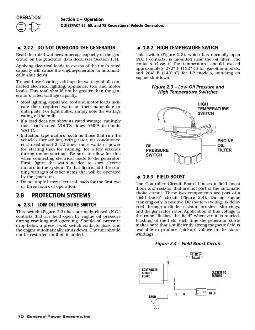
This switch (Figure 2.3) has normally closed (N.C.)contacts that are held open by engine oil pressureduring cranking and operating. Should oil pressuredrop below a preset level, switch contacts close, andthe engine automatically shuts down. The unit shouldnot be restarted until oil is added.
2.8.2 HIGH TEMPERATURE SWITCHThis switch (Figure 2.3), which has normally open(N.O.) contacts, is mounted near the oil filter. Thecontacts close if the temperature should exceedapproximately 270º F (132º C) for gasoline models,and 284° F (140° C) for LP models, initiating anengine shutdown.
Figure 2.3 – Low Oil Pressure and High Temperature Switches
2.8.3 FIELD BOOSTThe Controller Circuit Board houses a field boostdiode and resistor that are not part of the automaticchoke circuit. These two components are part of a“field boost” circuit (Figure 2.4). During enginecranking only, a positive DC (battery) voltage is deliv-ered through a diode, resistor, brushes, slip rings,and the generator rotor. Application of this voltage tothe rotor “flashes the field” whenever it is started.Flashing of the field each time the generator startsmakes sure that a sufficiently strong magnetic field isavailable to produce “pickup” voltage in the statorwindings.
Figure 2.4 – Field Boost Circuit
◆
◆
◆
◆

Generac® Power Systems, Inc. 11
Section 3 – MaintenanceQUIETPACT 55, 65, and 75 Recreational Vehicle Generators
2.8.4 OVERVOLTAGE PROTECTIONA solid-state voltage regulator (Figure 2.5) controlsthe generator’s AC output voltage. This regulator sup-plies an excitation current to the rotor. By regulatingthe rotor’s excitation current, the strength of its mag-netic field is regulated and, in turn, the voltage deliv-ered to connected electrical loads is controlled. Whenthe AC frequency is 60 Hertz, voltage is regulated at115 volts.
Figure 2.5 – Solid State Voltage Regulator
The voltage regulator also incorporates a “voltagesurge protection circuit.” This circuit prevents trou-blesome surges in the generator AC output voltage.Voltage surge is a common cause of damage to elec-tronic equipment.
2.8.5 25-HOUR BREAK-IN PERIODThe first 25 hours of operation is the break-in periodfor the generator. Properly breaking in the generatoris essential to minimize fuel consumption and pro-vide maximum engine performance. During this 25-hour break-in period, follow this procedure:
• Run the unit at varying electrical loads to help seatthe engine piston rings properly.
• Check the engine oil level frequently. Add oil ifneeded. It is normal for the generator engine toconsume more oil than is normal until the pistonrings have properly seated.
• For the 75-hour operation following the break-inperiod, avoid light electrical loads. Load the generator at 50 percent (or more) of its ratedwattage capacity. Repeated light loads during these75 hours can cause improper seating of engine pis-ton rings, resulting in blowby and high oil con-sumption.
• After operating the unit for 25 hours, complete thetasks recommended under Section 2.8.6.
2.8.6 25-HOUR CHECK-UPAfter the 25-hour break-in period, contact a GeneracAuthorized Service Dealer for the following mainte-nance. (The vehicle owner is responsible for anycharges relating to normal unit maintenance.)
• Change the engine crankcase oil and oil filter.• Check all fluid levels.• Inspect the cooling and ventilation openings.• Check the engine ignition system.• Inspect the entire electrical system.• Inspect the engine exhaust system.
2.8.7 OPERATION IN HIGH GRASSOR BRUSH
Never operate the generator while the vehicleis parked over high grass, weeds, brush,leaves or any other combustible substance.Such materials can ignite and burn from theheat of the exhaust system. The generatorexhaust system becomes extremely hot dur-ing operation and remains hot for a long timeafter it has shut down.
3.1 CHECKING THE ENGINE OILLEVEL
For oil capacities and requirements, see “Engine OilRequirements,” Section 1.6.2. Check the enginecrankcase oil level at least every eight hours of oper-ation, or before it is used. To check the engine oillevel, proceed as follows (see Figure 3.1):
1. Be sure the generator is as level as possible.2. Remove the dipstick and wipe it dry with a clean,
lint-free cloth.3. Install and tighten the dipstick cap; then, remove
it again. The oil level should be at the dipstick“Full” mark.
4. If necessary, remove the oil fill cap on the rockercover and slowly add oil until it reaches the dip-stick “Full” mark. DO NOT FILL ABOVE THE“FULL” MARK.
Never operate the engine with the oil levelbelow the “Add” mark on the dipstick. Doingthis could damage the engine.
5. Install and tighten the oil fill cap and the dipstickbefore operating the engine.
!
◆
◆
◆
◆

12 Generac® Power Systems, Inc.
Section 3 – MaintenanceQUIETPACT 55, 65, and 75 Recreational Vehicle Generators
3.2 CHANGING THE ENGINE OILAND/OR OIL FILTER
• Change the engine oil after the first 25 hours ofoperation (after the 25-hour break-in period, seeSection 2.8.5). Thereafter, change the oil every 100operating hours. Change the oil more frequently ifoperating consistently under heavy load or at highambient temperatures.
• Change the engine oil filter after the first 25 hoursof operation, and every 100 operating hours there-after.
To change the oil and/or oil filter, proceed as follows:
1. Run the engine until it is thoroughly warmed up(at least five minutes) then shut OFF the engine.
2. With the engine still warm from running, removethe oil drain plug (Figure 3.1). Drain the oil intoa suitable container.
Figure 3.1 — Oil Dipstick/Fill Tube andLocation of Oil Drain Plug
3. After the oil has drained, replace the oil drainplug. (If only changing the oil, go to step 7.)
4. With the oil drained, remove the old oil filter byturning it counterclockwise (Figure 3.2).
5. Apply a light coating of clean engine oil to the gas-ket of the new filter.
6. Screw the new filter on by hand until its gasketlightly contacts the oil filter adapter. Then, tight-en the filter an additional 3/4 to one turn.
7. Remove the dipstick and fill crankcase with theproper type and amount of recommended oil (seeSection 1.6.2). The engine crankcase can holdabout 1.8 liters or 1.9 quarts with oil filterchange. DO NOT FILL ABOVE THE “FULL”MARK.
8. Install and tighten the dipstick before operatingthe engine.
9. Start the engine and check for leaks.
Figure 3.2 — Engine Oil Filter
NOTE:
Check the oil level and fill to the “FULL” mark afterchecking for leaks. The filter will retain some oil.
3.3 MAINTAINING THE ENGINEAIR CLEANER
3.3.1 CLEANING THE FOAM PRECLEANERClean and re-oil the foam precleaner every threemonths or every 25 hours of operation, whicheveroccurs first. Service the foam precleaner more fre-quently if operating the generator in extremely dustyor dirty conditions. Use the following procedure(Figure 3.3):
1. Turn the knob counterclockwise to loosen.2. Remove the cover, foam precleaner and paper fil-
ter.3. Remove the foam precleaner from the cover.4. Wash the foam precleaner in liquid detergent and
water.5. Wrap the foam precleaner in a clean cloth and
gently squeeze it dry.6. Saturate the foam precleaner in clean engine oil.
Gently squeeze it in a clean cloth to removeexcess oil and to distribute oil (DO NOT TWIST).
7. Install the foam precleaner into the cover, fol-lowed by the paper filter. Tabs at edges of paperfilter must lock into slots on cover.
8. Install the cover, foam precleaner and paper filter.9. Replace knob to retain the filter in place.
◆
Oil Dipstick
Oil Drain Hose

Section 3 – MaintenanceQUIETPACT 55, 65, and 75 Recreational Vehicle Generators
Figure 3.3 – Engine Air Cleaner
3.4 CHECKING THE ENGINE SPARK PLUG
Clean the spark plug and reset the spark plug gapevery 100 hours of operation.
1. Clean the area around the base of the spark plugto keep dirt and debris out of the engine. Clean byscraping or washing using a wire brush and com-mercial solvent. Do not blast the spark plug toclean.
2. Remove the spark plug and check the condition.Replace the spark plug if worn or if reuse is ques-tionable.
3. Check the spark plug gap using a wire feelergauge. Adjust the gap to 0.030 inch (0.76 mm) by carefully bending the ground electrode (Figure 3.4).
Figure 3.4 – Setting the Spark Plug Gap
Sparking can occur if the wire terminal doesnot fit firmly on the spark plug terminal end. Ifnecessary, re-form the wire terminal to obtain atight fit.
3.5 FUEL FILTER (GASOLINE ONLY)Remove and replace the fuel filter (Figure 3.5) once each year or every 400 hours of operation,whichever comes first.
Figure 3.5 – Fuel Filter
3.6 CLEAN SPARK ARRESTORThe engine exhaust muffler has a spark arrestorscreen. Inspect and clean the screen every 50 hoursof operation or once each year, whichever comes first.
NOTE:
If using the generator on any forest-covered,brush-covered or grass-covered unimproved land,it must equipped with a spark arrestor. The sparkarrestor must be maintained in good condition bythe owner/operator.
Clean and inspect the spark arrestor as follows:
• Remove the screen retaining bracket by removingthe screw.
• Slide the spark arrestor screen out from the tailpipe.
• Inspect screen and replace if torn, perforated orotherwise damaged. DO NOT USE a defectivescreen. If screen is not damaged, clean it with com-mercial solvent.
• Replace the screen and the retaining bracket.
Figure 3.6 - Spark Arrestor
RETAINING SCREW
SPARK ARRRESTORSCREEN
TAILPIPE
RETAINER
!
WingNut
Offset S
A
P l
FlatWasher
WingNut
x Compartment
Generac® Power Systems, Inc. 13
TO FUEL PUMP
CUSTOMER FUEL CONNECTION
FUEL FILTER
P/N 0E0907
P/N 0D5133A
P/N 0D5133
P/N 045764

14 Generac® Power Systems, Inc.
3.7 CLEANING THE GENERATORKeep the generator set as clean and dry as possible.Protect the unit against excessive dust, dirt, corrosivevapors, road splash, etc. Permitting dirt and mois-ture to accumulate on generator windings will havean adverse effect on the insulation resistance of thosewindings.
When moisture is allowed to remain in contact withwindings, some of the moisture will be retained invoids and cracks in the insulation. This causes areduced insulation resistance and will eventuallycause problems. Dirt will make the problem worse,since dirt tends to hold moisture in contact withwindings. Salt (as from sea air) also will worsen theproblem since it tends to absorb moisture from theair. Salt and moisture, when combined, form a goodelectrical conductor which is detrimental to the gen-erator.
Do NOT use a forceful spray of water to cleanthe generator. Water will enter the generatorinterior and cause problems, and may also cont-aminate the generator fuel system.
3.8 BATTERY MAINTENANCEAll lead-acid batteries will discharge when not in use.The generator battery should be inspected as follows:
3.8.1 WEEKLY• Inspect the battery posts and cables for tightness
and corrosion. Tighten and clean as necessary.• Check the battery fluid level of unsealed batteries
and, if necessary, fill with Distilled Water Only. Donot use tap water in batteries.
3.8.2 EVERY SIX MONTHS• Have the state of charge and condition checked.
This should be done with an automotive-type bat-tery hydrometer.
NOTE:
Servicing of the battery is to be performed orsupervised by personnel knowledgeable of batter-ies and the required precautions. Keep unautho-rized personnel away from batteries.
Damage will result if the battery connections aremade in reverse.
Do not dispose of the battery in a fire. The battery is capable of exploding. Storage batter-ies give off explosive hydrogen gas. This gascan form an explosive mixture around the bat-tery for several hours after charging. Theslightest spark can ignite the gas and cause anexplosion. Such an explosion can shatter thebattery and cause blindness or other injury.Any area that houses a storage battery must beproperly ventilated. Do not allow smoking,open flame, sparks, or any spark producingtools or equipment near the battery. Dischargestatic electricity from body before touching thebattery by first touching a grounded metal sur-face.A battery presents a risk of electrical shock and high short circuit current. The followingprecautions are to be observed when workingon batteries:
• Remove watches, rings or other metal objects;• Use tools with insulated handles;• Wear rubber gloves and boots;• Do not lay tools or metal parts on top of the
battery;• Disconnect any charging source prior to connecting
or disconnecting battery terminals; and• Do not use any jumper cables or booster battery to
crank and start the generator engine. If any batteryhas discharged, remove it for recharging.
Do not open or mutilate the battery. Releasedelectrolyte has been known to be harmful tothe skin and eyes, and to be toxic.The electrolyte is a dilute sulfuric acid that isharmful to the skin and eyes. It is electricallyconductive and corrosive. The following procedures are to be observed:
• Wear full eye protection and protective clothing;• Where electrolyte contacts the skin, wash it off
immediately with water;• Where electrolyte contacts the eyes, flush
thoroughly and immediately with water and seekmedical attention; and
• Spilled electrolyte is to be washed down with anacid neutralizing agent. A common practice is touse a solution of 1 pound (500 grams) bicarbonateof soda to 1 gallon (4 liters) or water. The bicar-bonate of soda solution is to be added until theevidence of reaction (foaming) has ceased. Theresulting liquid is to be flushed with water and thearea dried.
!
!
DANGER
◆
◆
!
Section 3 – MaintenanceQUIETPACT 55, 65, and 75 Recreational Vehicle Generators
Generac® Power Systems, Inc. 15
3.9 MAJOR SERVICE MANUALTo obtain a service manual for the generator, contactthe nearest Generac Authorized Service Dealer. Makesure to identify the MODEL NUMBER and SERIES.Manuals can be obtained from the internet website(www.generac.com) or a service dealer.
3.10 DRIVE BELTThe engine drives the generator rotor by means of apulley and drive belt arrangement. Drive belt tensionwas properly adjusted before the unit was shippedfrom the factory. If suspect that drive belt tension isincorrect, contact a Generac Authorized ServiceDealer.
3.11 EXERCISING THE GENERATORGenerac recommends starting and operating the gen-erator at least once every seven days. Let the unit runfor at least 30 minutes to “exercise” the engine.
3.12 OUT OF SERVICE PROCEDURE
3.12.1 REMOVAL FROM SERVICEIf the generator cannot be exercised every seven days,and it is to be out of service longer than 30 days, pre-pare the generator for storage as follows:
1. Start the engine and let it warm up.2. Close the fuel shutoff valve in the fuel supply line
and allow the unit to shut down.3. While the engine is still warm from running,
drain the oil completely. Refill the crankcase withSAE 5W-30 oil having API classification “ForService SF.”
4. Attach a tag to the engine indicating the viscosityand classification of the oil in the crankcase.
5. Remove the spark plug and pour two or threetablespoons of clean, fresh engine oil into thespark plug threaded openings. Reinstall andtighten the spark plug.
6. Remove the battery and store it in a cool, dryroom on a wooden board. Never store the batteryon any concrete or earthen floor.
7. Clean and wipe the entire generator.
3.12.2 RETURN TO SERVICETo return the unit to service after storage, proceed as follows:
1. Check the tag on the engine for oil viscosity andclassification. Verify that the correct recommend-ed oil is used in the engine (see Section 1.5.4). Ifnecessary, drain and refill with the proper oil.
2. Check the state of the battery. Fill all cells ofunsealed batteries to the proper level with distilledwater. DO NOT USE TAP WATER IN THE BAT-TERY. Recharge the battery to 100 percent state ofcharge, or, if defective, replace the battery.
3. Clean and wipe the entire generator.4. Reconnect the battery. Observe battery polarity.
Damage may occur if the battery is connectedincorrectly.
5. Turn OFF all electrical loads. Add fuel if neces-sary and then start the engine.
6. Allow the unit to warm up thoroughly.7. Apply electrical loads to at least 50 percent of the
unit’s rated wattage capacity.8. When the engine is thoroughly warmed up, shut
it down.9. The generator is now ready for service.
3.13 RV GENERATOR SERVICEINTERVAL
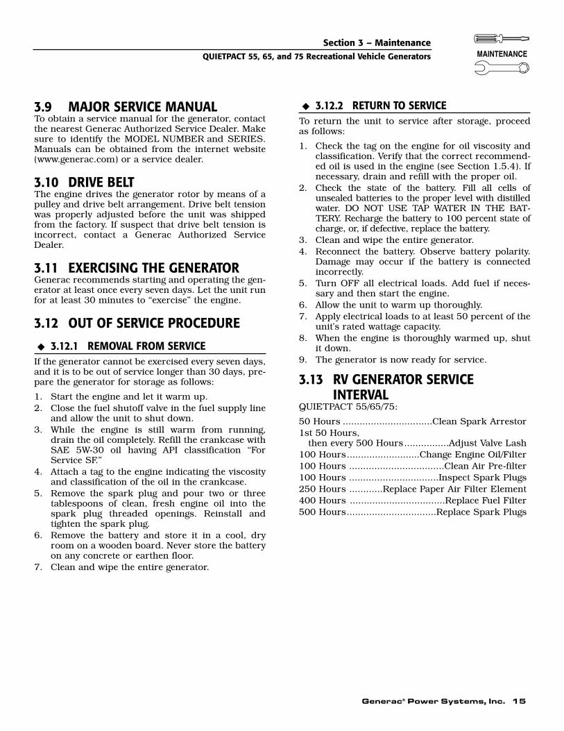
QUIETPACT 55/65/75:
50 Hours ................................Clean Spark Arrestor1st 50 Hours,
then every 500 Hours................Adjust Valve Lash100 Hours..........................Change Engine Oil/Filter100 Hours ..................................Clean Air Pre-filter100 Hours ................................Inspect Spark Plugs250 Hours ............Replace Paper Air Filter Element400 Hours ..................................Replace Fuel Filter500 Hours................................Replace Spark Plugs
◆
◆
Section 3 – MaintenanceQUIETPACT 55, 65, and 75 Recreational Vehicle Generators

16 Generac® Power Systems, Inc.
Section 4 – NotesQUIETPACT 55, 65, and 75 Recreational Vehicle Generators

PART II –INSTALLATIONINSTRUCTIONS
ONLY QUALIFIED ELECTRICIANS OR CONTRACTORS SHOULD ATTEMPT INSTALLATION!!
DANGER

18 Generac® Power Systems, Inc.
Safety RulesQUIETPACT 55, 65, and 75 Recreational Vehicle Generators
NOTICE TO INSTALLERThese Installation Instructions have been publishedby Generac to aid in the installation of the productsdescribed in this manual. Generac assumes thatinstallation personnel are familiar with the proce-dures for installing such products, or similar prod-ucts that Generac manufactures. Generac alsoassumes that personnel have been trained in the rec-ommended installation procedures for these prod-ucts and that such training includes (a) use of com-mon hand tools, (b) use of special Generac tools, and(c) use of any tools and/or equipment from other sup-pliers.
Generac cannot possibly know of and advise therecreational vehicle trade of all conceivable methods,procedures or techniques by which to perform aninstallation. Nor can Generac anticipate every possi-ble hazard that might result from each installationmethod, procedure or technique. Generac has notundertaken any such wide evaluation. Therefore,people who use a method, procedure or techniquethat Generac does not specifically recommend mustfirst completely satisfy themselves that their safety,the safety of the vehicle's occupants and the product'ssafety is not endangered by the method, procedure ortechnique selected.
Information, illustrations, specifications, etc., con-tained in these Installation Instructions are based onthe latest information available at the time of publi-cation. Every effort has been expended to be sure thatsuch data is both accurate and current. However, themanufacturer reserves the right to change, alter orotherwise improve this product at any time withoutprior notice.
Despite the safe design of this generator, operating this equipment imprudently, neglectingits maintenance or being careless can cause possible injury or death. Permit only responsibleand capable persons to operate or maintain thisequipment.
Potentially lethal voltages are generated bythese machines. Ensure all steps are taken torender the machine safe before attempting towork on the generator.
Parts of the generator are rotating and/or hotduring operation. Exercise care near runninggenerators.
GENERAL HAZARDS
• For safety reasons, Generac recommends that the installation, initial start-up and mainte-nance of this equipment is carried out by aGenerac Authorized Service Dealer.
• The generator engine releases DEADLY carbonmonoxide gas through its exhaust system. Thisdangerous gas, if breathed in sufficient concentra-tions, can cause unconsciousness or even death.Never operate the generator set with the vehicleinside any garage or other enclosed area. DO NOTOPERATE THE GENERATOR IF THE EXHAUSTSYSTEM IS LEAKING OR HAS BEEN DAMAGED.SYMPTOMS OF CARBON MONOXIDE POISON-ING ARE (a) inability to think coherently, (b) nau-sea, (c) vomiting, (d) twitching muscles, (e) throb-bing temples, (f) dizziness, (g) headaches, (h)weakness, and (i) sleepiness. IF EXPERIENCINGANY OF THESE SYMPTOMS, MOVE INTO FRESHAIR IMMEDIATELY. IF SYMPTOMS PERSIST, GETMEDICAL HELP. Shut down the generator and donot operate it until it has been inspected andrepaired.
• Never sleep in the vehicle while the genset is run-ning unless the vehicle has a working carbonmonoxide detector. The exhaust system must beinstalled in accordance with the genset installationmanual. Make sure there is ample fresh air whenoperating the genset in a confined area.
• Keep hands, feet, clothing, etc., away from drivebelts, fans, and other moving or hot parts. Neverremove any drive belt or fan guard while the unit isoperating.
• Adequate, unobstructed flow of cooling and venti-lating air is critical to correct generator operationand is required to expel toxic fumes and fuelvapors from the generator compartment. Withoutsufficient cooling airflow, the engine/generatorquickly overheats, which causes serious damage tothe generator. Do not alter the installation or per-mit even partial blockage of ventilation provisions,as this can seriously affect safe operation of thegenerator.
• When working on this equipment, remain alert atall times. Never work on the equipment whenphysically or mentally fatigued.
• Before performing any maintenance on the genera-tor, disconnect its battery cables to prevent acci-dental start up. Disconnect the cable from the bat-tery post indicated by a NEGATIVE, NEG or (–)first. Reconnect that cable last.
!!
!
!
DANGER
DANGER: For fire safety, installation of a generator into a recreational vehicle must comply strictlywith article 551, NFPA 70; ANSI C1-1975; AND, ANSI A119.2-1975/NFPA 501C “Standard forRecreational Vehicles” (Part 3, “Installation of Electrical Systems”). In addition, installation mustcomply with the manufacturer’s instructions and recommendations.
!

Generac® Power Systems, Inc. 19
Safety RulesQUIETPACT 55, 65, and 75 Recreational Vehicle Generators
• Never use the generator or any of its parts as astep. Stepping on the unit can stress and breakparts, and may result in dangerous operating con-ditions from leaking exhaust gases, fuel leakage,oil leakage, etc.
• Never insert any tool or other object through open-ings in the generator interior, even if the unit is notrunning. serious injury or damage to the equip-ment could be done.
ELECTRICAL HAZARDS• The generator covered by this manual produces
dangerous electrical voltages and can cause fatalelectrical shock. Avoid contact with bare wires, ter-minals, connections, etc., while the unit is running.Ensure all appropriate covers, guards and barriersare in place before operating the generator. If workmust be done around an operating unit, stand onan insulated, dry surface to reduce shock hazard.
• Do not handle any kind of electrical device whilestanding in water, while barefoot, or while handsor feet are wet. DANGEROUS ELECTRICALSHOCK MAY RESULT.
• During installation onto the vehicle, properlyground (bond) the generator either by solid mount-ing to the vehicle frame or chassis, or by means ofan approved bonding conductor. DO NOT connectthe bonding conductor to any generator part thatmight be removed or disassembled during routinemaintenance. If the grounding conductor must bereplaced, use only a flexible conductor that is ofNo. 8 American Wire Gauge (AWG) copper wireminimum.
• If the vehicle electrical circuits can be powered byany other source of electricity (such as a “dockside”power receptacle), there must be no possibility ofconnecting the different power sources to the vehi-cle circuits at the same time. The dockside (utility)power source must be positively isolated from thevehicle circuits whenever the generator is operating.Failure to isolate the vehicle circuits from the dock-side power supply when the generator is runningmay result in damage to the generator or seriousinjury or death to dockside (utility) power workersdue to backfeed of electrical energy.
• In case of accident caused by electric shock, imme-diately shut down the source of electrical power. Ifthis is not possible, attempt to free the victim fromthe live conductor. AVOID DIRECT CONTACT WITHTHE VICTIM. Use a nonconducting implement,such as a rope or board, to free the victim from thelive conductor. If the victim is unconscious, applyfirst aid and get immediate medical help.
• Never wear jewelry when working on this equip-ment. Jewelry can conduct electricity resulting inelectric shock, or may get caught in moving com-ponents causing injury.
FIRE HAZARDS
• For fire safety, the generator must be installed andmaintained properly. Installation always mustcomply with applicable codes, standards, laws andregulations. Adhere strictly to local, state andnational electrical and building codes. Complywith regulations the Occupational Safety andHealth Administration (OSHA) has established.Also, ensure that the generator is installed inaccordance with the manufacturer’s instructionsand recommendations. Following proper installa-tion, do nothing that might alter a safe installationand render the unit in noncompliance with theaforementioned codes, standards, laws and regu-lations.
• Keep a fire extinguisher in the vehicle at all times.Extinguishers rated “ABC” by the National FireProtection Association are appropriate for use onthe recreational vehicle generator electrical system.Keep the extinguisher properly charged and befamiliar with its use. If there are any questions per-taining to fire extinguishers, consult the local firedepartment.
EXPLOSION HAZARDS• Do not smoke around the generator. Wipe up any
fuel or oil spills immediately. Ensure that no com-bustible materials are left in the generator com-partment, or on or near the generator, as FIRE orEXPLOSION may result. Keep the area surround-ing the generator clean and free from debris.
• Gasoline is extremely FLAMMABLE and its vaporsare EXPLOSIVE. Do not permit smoking, openflame, sparks or any source of heat in the vicinitywhile handling gasoline. Comply with all laws gov-erning the storage and handling of gasoline.
• Fuel lines must be properly installed and fastened, and free of leaks. There must be no possibility of gasoline vapors entering the vehi-cle interior.
• It is required that an approved, flexible, noncon-ductive fuel line between the generator fuel con-nection point and rigid fuel lines be installed.
• If the generator is equipped with a liquid propane(LP) gas fuel system, install the unit so it complieswith all codes, standards and regulations pertain-ing to such systems. LP gas is highly explosive. Thegas tends to settle in low areas where even theslightest spark can ignite it and cause an explo-sion. Do not allow gas vapors to enter the vehicle.
20 Generac® Power Systems, Inc.
5.1 PURPOSE AND SCOPE OF THEINSTALLATION INSTRUCTIONS
These Installation Instructions have been preparedespecially for the purpose of familiarizing installersand owners of the applicable equipment with theproduct's installation requirements. Give seriousconsideration to all information and instructions inthe manual, both for safety and for continued reliableoperation of the equipment.
Because of the different recreational vehicle modelsand the variations between the models, it would beextremely difficult, if not impractical, to providedetailed instructions for every possible installation.For that reason, instructions and illustrations in thismanual are general in nature. Illustrations are notintended to serve as detailed installation blueprints.
The installation should comply strictly with allapplicable codes, standards and regulations pertain-ing to the installation and use of this product. If anyportion of this manual appears to be in conflict withsuch codes, standards or regulations, the applicablecodes, standards or regulations must take prece-dence over the manual.
5.2 SAFETYBefore handling, installing, operating or servicing thisequipment, carefully read the “Notice to Installer”and “Safety Rules” on pages 18 and 19. Comply withall safety rules to prevent death, personal injury ordamage to equipment and/or property. Stress safetyto all installers, operators and service technicianswho work on this equipment.
5.3 STANDARDS BOOKLETSInstallation, use and servicing of this equipmentshould comply strictly with published standards, aswell as the manufacturer's recommendations. Thefollowing standards booklets (latest revision) areavailable from the sources indicated:
1. NFPA Standard 501C, “Standard for RecreationalVehicles,” available from the National FireProtection Association, Batterymarch Park,Quincy, MA 02269.
2. NFPA 70, “NFPA Handbook of the NationalElectric Code,” available same as Item 1.
3. ANSI C1-1975 and ANSI 119.2-1975, availablefrom the American National Standards Institute,1430 Broadway, New York, NY 10018.
4. ANSI A119.2/NFPA 501C, available from theRecreational Vehicle Association, 1896 PrestonWhite Drive, Reston, VA 22090.
5. California Administrative Code, Title 25, avail-able from the State of California, DocumentsSection, P.O. Box 1015, North Highlands, CA95660.
6. CSA Electrical Bulletin 946, available from theCanadian Standards Association, Housing andConstructions Materials Section, 178 RexdaleBoulevard, Rexdale, Ontario, Canada, M9W 1R3.
5.4 EQUIPMENT DESCRIPTIONInstructions and information in this section pertainto Generac air-cooled generators. These generatorsare designed specifically for installing in recreationalvehicles. They operate 120-volt, single-phase, 60-Hertz, AC electrical loads.
5.5 GENERATOR ENGINEOPERATING SPEED
The generator’s revolving field (rotor) is driven by atwo-cylinder, four-cycle engine through a pulley anddrive belt arrangement. The generator supplies 120volts AC at 60 Hertz when the rotor is operating at3,600 rpm.The drive belt arrangement allows theengine to operate at a lower speed than the rotor.
5.6 GENERATOR AC CONNECTION SYSTEM
These air-cooled generator sets are equipped with dualstator AC power windings. These two stator windingssupply electrical power to customer electrical loads bymeans of a dual 2-wire connection system.
Generators may be installed to provide the followingoutputs:
1) 120 VAC loads only — one load with a maximumtotal wattage requirement equal to the generator’srated power output (in watts), and 120V across thegenerator output terminals. (See Fig. 5.1 below)
2) 120/240 VAC loads — one load with a maximumtotal wattage requirement equal to the generator’srated power output, and 240 V across the generatoroutput terminals; or two seperate loads, each with amaximum total wattage requirement equal to half ofthe generator’s rated power output (in watts), and120 V across the generator output terminals. (See Fig.5.3 on page 22.)
Figure 5.1 – Connection for 120 Volts Only
Section 5 – General InformationQUIETPACT 55, 65, and 75 Recreational Vehicle Generators

Generac® Power Systems, Inc. 21
Figure 5.2 - Major Features and Dimensions (Drawing No. 0E1058-E)
Section 5 – General InformationQUIETPACT 55, 65, and 75 Recreational Vehicle Generators
A
B
C
C
545
[ 21
7/16
"]
TYP.
95.6
[ 3 3
/4"]
183.
6[ 7
1/4
"]
821.
2[ 3
2 5/
16"]
233.
2[ 9
3/1
6"]
469
[ 18
7/1
6"]
195.
8[ 7
11/
16"]
57[ 2
1/4
"]
TYP.
516.
2[ 2
0 5/
16"]
TYP.
469.
8[ 1
8 1/
2"]
495
[ 19
1/2"
]52
6.2
[ 20
11/1
6"]
70.8
[ 2 1
3/16
"]
344.
6[ 1
3 9/
16"]
45°
305.
9[ 1
2 1/
16"]
536.
2[ 2
1 1/
8"]
TYP.
54[ 2
1/8
"]
126.
2[ 5
"]
90[ 3
9/1
6"]
497.
4[ 1
9 9/
16"]
REF
.85
5.8
[ 33
11/1
6"]
REF
.56
4.1
[ 22
3/16
"]
190.
4[ 7
1/2
"] 120.
5[ 4
3/4
"]
212
[ 8 3
/8"]
84[ 3
5/1
6"]
89.4
[ 3 1
/2"]
39.8
[ 1 9
/16"
]
TYP.
50[ 1
15/
16"]
470
[ 18
1/2"
]
513.
7[ 2
0 1/
4"]
AIR
INTA
KE
HO
T AI
REX
HAU
ST
3/8"
-16
WEL
DN
UTS
(8 P
LAC
ES)
FUEL
FIL
TER
REM
OTE
PAN
ELC
ON
NEC
TOR
AC O
UTP
UT
HAR
NES
S
BATT
ERY
CO
NN
ECTI
ON
S
FRO
NT
TAIL
PIPE
LOC
ATIO
N
FUEL
INLE
T
FUEL
INLE
T
25.4
[ 1"]
TYP.
6.7
[ 1/4
"]
274
[ 10
13/1
6"]
293
[ 11
9/16
"]84
2.4
[ 33
3/16
"]
VIEW
FR
OM
TO
P
FRO
NT
DO
OR
AC
CES
S FO
RAL
L R
EQU
IRED
MAI
NTE
NAN
CE
NO
TE: A
LL A
IR IN
TAKE
S AN
D E
XHAU
ST O
UTL
ETS
MU
ST B
E
KEP
T C
LEAR
OF
ANY
OBS
TRU
CTI
ON
S. A
LL O
PEN
AR
EA
IS
REQ
UIR
ED F
OR
CO
OLI
NG
.
568
[ 22
3/8"
]
219.
8[ 8
5/8
"]
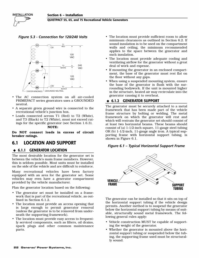
22 Generac® Power Systems, Inc.
Figure 5.3 - Connection for 120/240 Volts
• The AC connection system on all air-cooledPRIMEPACT series generators uses a GROUNDEDneutral.
• A separate green ground wire is connected to therecreational vehicle’s junction box.
• Loads connected across T1 (Red) to T2 (White),and T3 (Black) to T2 (White), must not exceed rat-ings for the specific generator (see Section 1.6.3).
NOTE:
Do NOT connect loads in excess of circuit breaker ratings.
6.1 LOCATION AND SUPPORT6.1.1 GENERATOR LOCATION
The most desirable location for the generator set isbetween the vehicle's main frame members. However,this is seldom possible. Most units must be installedon the side of the vehicle and are difficult to reinforce.
Many recreational vehicles have been factoryequipped with an area for the generator set. Somevehicles may even have a generator compartmentprovided by the vehicle manufacturer.
Plan the generator location based on the following:
• The generator set must be installed on a frame-work that is part of the recreational vehicle, as out-lined in Section 6.1.2.
• The location must provide an access opening thatis large enough to permit generator removal(unless the generator is to be removed from under-neath the supporting framework).
• The location must provide easy access to frequent-ly serviced components, such as filters, oil drains,spark plugs and other common maintenanceparts.
• The location must provide sufficient room to allowminimum clearances as outlined in Section 6.2. Ifsound insulation is to be used on the compartmentwalls and ceiling, the minimum recommendedapplies to the space between the generator andsuch insulation.
• The location must provide adequate cooling andventilating airflow for the generator without a greatdeal of work and expense.
• If mounting the generator in an enclosed compart-ment, the base of the generator must rest flat onthe floor without any gaps.
• When using a suspended mounting system, ensurethe base of the generator is flush with the sur-rounding bodywork. If the unit is mounted higherin the structure, heated air may recirculate into thegenerator causing it to overheat.
6.1.2 GENERATOR SUPPORTThe generator must be securely attached to a metalframework that has been made part of the vehicleframe structure by bolting or welding. The metalframework on which the generator will rest andwhich will restrain the generator set should consist ofat least two horizontal beams. These beams shouldconsist of (a) 1-1/2-inch square, 11-gauge steel tubingOR (b) 1-1/2-inch, 11-gauge angle iron. A typical sup-porting frame with horizontal support tubing, isshown in Figure 6.1.
Figure 6.1 – Typical Horizontal Support Frame
The generator can be installed so that it sits on top ofthe horizontal support tubing if the vehicle designpermits. Another method is to suspend the generatorbelow the horizontal support tubing by means of suit-able, structurally sound metal framework. The fol-lowing general rules apply:
• Vehicle construction MUST be capable of support-ing the weight of the generator.
• Whether the generator is mounted above the hori-zontal support tubing or suspended below the tub-ing, the supporting frame used must be structural-ly sound.
◆
◆
T1RED
T2WHITE
T3BLACK
GROUNDED NEUTRALSTATOR WINDINGS
CB1
CB2
Section 6 – InstallationQUIETPACT 55, 65, and 75 Recreational Vehicle Generators

Generac® Power Systems, Inc. 23
• If the generator cannot be bolted directly to the supporting frame or support tubing, considerusing additional tubing, angle brackets or othersupports to give the supporting frame sufficientstrength.
6.1.3 SUSPENDED MOUNTINGIf planning to suspend the generator below the hori-zontal support tubing, the suspension method to usewith the vehicle frame members must (a) be able tosupport the weight of the generator AND (b) providesufficient restraint for the generator. One typical sus-pended mounting system is shown in Figure 6.2. Thelocation of a suspended mounting system must becarefully planned, keeping the following general rulesin mind:
• Protect the generator against road splash anddebris. Baffles or splash guards may be requiredto protect certain areas of the generator. To makesure the generator is adequately protected, roadtest the installation through mud, water and slush.
Figure 6.2 – Typical Suspended MountingSystem
• The installer must make certain that the selectedlocation will permit adequate cooling and ventilat-ing airflow to be supplied.
6.1.4 GENERATOR RESTRAINTUse four 3/8"-16 hardened steel bolts (Grade 5) tofasten the generator to the supporting frame or thesupport tubing. These bolts must pass through (a)the generator mounting base, (b) the compartmentfloor (if a compartment is used) and (c) the support-ing framework (Figure 6.3). All bolts must be longenough so that when tight, at least three threads arevisible past the retaining lock nuts. Refer to Section6.2 for the location of the generator mounting holes.
Figure 6.3 – Typical Generator Restraint
6.2 GENERATOR COMPARTMENTSWhether the generator set is being installed inside acompartment specifically manufactured to house a gen-erator or inside a compartment that the installer con-structs, the compartment MUST meet certain specifi-cations as outlined in the following sections:
6.2.1 COMPARTMENT SIZEPlan the compartment size carefully. Provide a mini-mum clearance of 1/2 inch (13 mm) on the front andtop, 1 inch (25 mm) on the sides, and 1/2 inch (13mm) from the back for air circulation AFTER thecompartment has been lined with metal and soundinsulation (Figure 6.4).
NOTE:
Refer to “Figure 5.2 – Major Features andDimensions” on page 21.
Figure 6.4 – Clearances
6.2.2 COMPARTMENT CONSTRUCTION• The generator compartment should be either con-
structed of, or lined with, 26-gauge galvanizedsteel.
NOTE:
Aluminum is NOT an acceptable alternative to galvanized steel due to aluminum’s low meltingpoint.
◆
1" Clearancein Back
1/2" Clearance on Top
1" Each Side
1/2"in Front
Insulation
PlywoodCompartment
18" Clearance Recommended
Below (Minimum 12")
◆
◆
◆
Section 6 – InstallationQUIETPACT 55, 65, and 75 Recreational Vehicle Generators

24 Generac® Power Systems, Inc.
• If the compartment is lined with galvanized steel, itmay be constructed of any material. Generac rec-ommends that the compartment be constructed of1/2-inch thick plywood (not strandboard), with thefloor made of a double thickness of 1/2-inch ply-wood with the grain of the wood at cross sectionfor added strength (Figure 6.5).
Figure 6.5 – Typical Compartment Construction
• If constructing a compartment, line the exterior(underside) of the compartment floor with 26-gauge galvanized steel.
• All seams, splices and joints of the compartmentwalls (unless vapor tight by design) should becaulked to prevent poisonous, flammable or explo-sive vapors from entering the vehicle interior.
NOTE:
Caulking must be done so that the caulking mate-rial will stay in place permanently. Pressing suchmaterials as putty tape onto joints and seams isnot acceptable. A high quality silicone rubber basesealant is recommended.
• Holes and openings made in the compartmentwalls to allow for the passage of electrical conduit,conductors, hoses, cables, etc., into the vehicle liv-ing area must be sealed vapor tight with siliconerubber base sealant.
• If flexible metal conduit is used, it must be sealedinternally at the end where it terminates inside thecompartment’s electrical junction box.
NOTE:
Flexible metal conduit, due to its unique con-struction, is NOT vapor tight along its entirelength.
• Seams and joints of the galvanized steel (whetherused as a liner or for the compartment itself) mustbe lapped and mechanically secured. Such seamsmay be manufactured, welded, bolted, riveted orscrewed. Manufactured lock seams are shown inFigure 6.6. Installer constructed compartmentstypically utilize a standard lap joint.
Figure 6.6 – Types of Lock Seams
• After the compartment has been metal lined andvapor sealed, line the compartment interior wallsand ceiling with an approved, nonflammablesound insulating material. See Section 6.2.3.
Do not install any flammable material directlyabove or around the compartment. Heat, transferred through the compartment structure,may be sufficient to ignite, char or discolor seat cushions, fiberboard and other flammablematerials. Use approved nonflammable insulat-ing materials in high temperature areas.
6.2.3 SOUND INSULATING MATERIALSOnce installers have determined that a compartmentis properly constructed and metal lined, they can addacoustical material. This may include additionalsealant or insulating material, to reflect noise awayfrom the vehicle interior.
Sound insulating materials should be of a nonflam-mable type. One excellent insulating material is a 1-inch (25 mm) thick fiberglass having a 2-pound den-sity. When fiberglass is used, its coated side shouldface toward the compartment interior.
Do not install sound insulation or anyabsorbent material on the compartment floorinterior. Such materials will become soakedwith combustible or explosive vapors and liq-uids and will become a fire hazard.
DANGER
◆
DANGER
Section 6 – InstallationQUIETPACT 55, 65, and 75 Recreational Vehicle Generators

Generac® Power Systems, Inc. 25
Section 6 – InstallationQUIETPACT 55, 65, and 75 Recreational Vehicle Generators
Using a combination of sound insulating materialscan often reduce noise more effectively than a singlematerial. For example, a sheet of lead or visco-elasticmaterial, along with a layer of other acoustical mate-rial, is more effective than when a single material isused.
6.2.4 ACOUSTICSFor additional noise abatement, the installer maywish to consider the following:
• Using special sound insulating materials.• Construction of a special noise abatement com-
partment.NOTE:
Any method used to reduce noise must notadversely affect the flow of cooling and ventilatingair into or out of the compartment.
In addition to the effective use of sound insulatingmaterials, construction of a special noise abatementcompartment might be considered to reduce noiselevels. Such a compartment might be constructed asfollows (Figure 6.7):
• Use 5/8-inch thick or 3/4-inch thick plywood in thecompartment.
• Construct the compartment floor of a double thick-ness of 5/8-inch or 3/4-inch plywood.
• Line the compartment interior walls and floor, aswell as the underside of the floor, with 26-gaugegalvanized steel.
• Vapor seal all compartment seams and joints.• Over the galvanized steel lining, install a combina-
tion of acoustical materials as mentioned inSection 6.2.3.
Figure 6.7 – Typical Noise Abatement
To prevent fire or explosion, do not install anyinsulation or other absorbent materials on theinterior or underside of the compartment floor.
• Seal all compartment door edges to prevent noiseleakage around the door perimeter.
• Line the compartment door interior (except for airopenings) with suitable, fireproof sound insulation(such as 1-inch (25 mm) thick fiberglass with a 2-pound density).
6.2.5 COMPARTMENT FLOOR CUTOUTSProvide openings in the generator compartment forthe following items (Figure 6.8, page 26):
• Engine exhaust and cooling air outlets• Generator cooling air inlet• Four holes for passage of generator mounting
bolts. See Section 6.1.4.
Fuel lines and exhaust piping must not pene-trate into the vehicle living area.
6.3 COOLING AND VENTILATING AIRIt is absolutely essential that an adequate flow of airfor cooling, ventilating and engine combustion besupplied to the generator set. Without sufficient air-flow, the engine/generator quickly overheats. Suchoverheating can cause serious operating difficultiesand also may cause fire and personal injury. Theinstaller must make sure that sufficient air is avail-able to the generator for cooling, ventilating and com-bustion. The installer also must provide for a pathfor exhausting the cooling air to the exterior of a com-partment, if so equipped.
Never use discharged cooling air for heating orpermit such air to enter the vehicle interior.This air contains deadly carbon monoxide gasand other poisonous, flammable or explosivegases.
6.3.1 GENERATOR AIRFLOWEngine operation drives cooling fans for the two-stagecooling air system. A pressure fan draws cooling airinto the top of the generator (Figure 6.9). This airflowcools the engine/generator and electronic compo-nents. The second part of the cooling system, a suc-tion fan, draws air that is heated from a hot engineinto a collector pan at the base of the unit. This heat-ed air (although cooler than exhaust muffler) is thendeflected out the bottom toward the ground.
◆
DANGER
!
DANGER
◆
DANGER
◆

26 Generac® Power Systems, Inc.
Figure 6.9 – Airflow Through Engine/Generator
6.3.2 TESTING THE INSTALLATIONGenerac recommends testing the installation to besure adequate cooling airflow is available to the unitbefore placing the unit into service. If the unit showssigns of overheating, enlarge the air openings. Neverplace a unit into service until absolutely certain thatcooling and ventilation is adequate.
NOTE:
The installation must be tested, especially if bring-ing in air from below the generator set.
6.4 GASOLINE FUEL SYSTEM
Gasoline is highly flammable, and its vapors areexplosive. Comply with all codes, standards andregulations pertaining to gasoline fuel systemsused in recreational vehicle generators.Properly install and maintain the fuel systemand keep it entirely free of leaks. Gasolinevapors must not enter the vehicle interior.
The installation of a gasoline fuel system (Figure6.10) for a recreational vehicle generator set mustcomply with applicable codes, standards and regula-tions. The entire fuel system must be completely freeof leaks. There must be no possibility of gasolinevapors entering the vehicle interior.
DANGER
◆
Section 6 – InstallationQUIETPACT 55, 65, and 75 Recreational Vehicle Generators
Figure 6.8 — Compartment Floor Cutout
A
B
545 [ 21 7/16"]
TYP.95.6
[ 3 3/4"]183.6
[ 7 1/4"]
821.2 [ 32 5/16"]
233.2 [ 9 3/16"]
469 [ 18 7/16"]
195.8 [ 7 11/16"]
57 [ 2 1/4"]
TYP.516.2
[ 20 5/16"]
TYP.469.8
[ 18 1/2"]
495 [ 19 1/2"]
526.2 [ 20 11/16"]
70.8 [ 2 13/16"]
344.6 [ 13 9/16"]
45°
305.9 [ 12 1/16"]
536.2 [ 21 1/8"]
TYP.54
[ 2 1/8"]
126.2 [ 5"]
90 [ 3 9/16"]
REF.564.1
[ 22 3/16"]AIR INTAKE
HOT AIREXHAUST
3/8"-16 WELDNUTS(8 PLACES)
FRONT
TAILPIPELOCATION
FUEL INLET
25.4 [ 1"]
TYP.6.7
[ 1/4"]
842.4 [ 33 3/16"]
VIEW FROM TOP
NOTE: ALL AIR INTAKES AND EXHAUST OUTLETS MUST BE KEPT CLEAR OF ANY OBSTRUCTIONS. ALL OPEN AREA IS REQUIRED FOR COOLING.
568 [ 22 3/8"]
219.8 [ 8 5/8"]

Generac® Power Systems, Inc. 27
Figure 6.10 – Generator Fuel System
Factory installed generator fuel system componentsinclude (a) fuel filter, (b) 12-volt DC electric pump, (c)engine carburetor, and (d) interconnecting lines andfittings. Connect a fuel supply line to the fuel filterinlet. Use a flexible length of approved fuel hosebetween the fuel filter inlet connection and rigid fuellines.
6.4.1 FUEL TANKEither the generator must share the vehicle engine'sfuel tank, or a separate fuel tank for the generator setmust be installed. All fuel tanks installed on the vehi-cle must be constructed, installed and restrained sothey comply with applicable codes, standards andregulations.
If the generator is to share the vehicle engine's tank,separate fuel pickup tubes are required for the engineand the generator. Generac recommends that the fuelpickup tube be two to three inches (51 to 76 mm)shorter than the vehicle engine's pickup tube. Thisprevents the generator from depleting the entire fuelsupply during prolonged generator operating peri-ods.
Do NOT tee the generator fuel supply line intothe vehicle engine fuel supply line. If this isdone, the generator will be starved of fuelwhen both engines are operating at the sametime. Also, while the vehicle engine is not run-ning, generator operation may drain the vehi-cle engine supply line, making it difficult tostart the vehicle engine.
6.4.2 GENERATOR FUEL SUPPLY LINE
6.4.2.1 Rigid Fuel LinesThose lines used to supply fuel from a tank to thegenerator must comply with applicable codes, stan-dards and regulations. The following general rulesapply to rigid fuel lines:
• Rigid lines should be of annealed, seamless, drawnaluminum or steel.
• Lines and fittings must comply with SAE J512F,“Standard Automotive Fittings,” or with ANSIB126.26 (latest edition).
• Route the fuel line so that at least 2 inches (51 mm)of clearance is maintained between the line andany exhaust system parts.
• Do not attach electrical wiring to fuel lines. Routethe wiring so it cannot come into contact with anyfuel line.
• Route fuel lines so if they leak, fuel does not driponto any electrical or exhaust system parts.
• Use nonferrous metal straps without sharp edgesto secure fuel lines.
6.4.2.2 Flexible Fuel LineUse an approved flexible length of fuel hose betweenthe generator fuel inlet connection and rigid fuellines. This prevents breaking of the line caused byvibration, shifting, settling or movement. The follow-ing rules apply:
• The flexible hose must comply with SAE J30B,“Standard for Fuel and Oil Hose.” It must beapproved for use with gasoline.
• The hose should be at least 6 inches (152 mm)longer than is needed to prevent the hose fromrupturing if the generator shifts or settles.
6.5 LP GAS FUEL SYSTEM
LP gas is highly EXPLOSIVE. The gas is heavierthan air and tends to settle in low areas. Eventhe slightest spark can ignite it and cause andexplosion. Only competent, qualified peopleshould be allowed to install, test, adjust or ser-vice an LP gas fuel system. Install the optionalfuel system in compliance with applicablecodes, standards and regulations. After theinstallation, do not do anything that might ren-der the system in noncompliance with applica-ble codes and standards.
The LP powered range of generators are fitted with anonadjustable, factory set system. These systems aretamper-proof to meet 1997 California Air ResourcesBoard requirements for engine emission.
6.5.1 LP FUEL CONSUMPTION (LB./HOUR)◆
DANGER
◆
!
◆
Fuel Pump(Behind AccessCover)
Fuel Filter(Side of Unit)
Fuel Line
Section 6 – InstallationQUIETPACT 55, 65, and 75 Recreational Vehicle Generators
Model Idle 50% Load 100% LoadQuietpact 55LP 2.34 3.96 5.07Quietpact 65LP 2.34 4.20 6.50Quietpact 75LP 2.34 4.44 8.75

28 Generac® Power Systems, Inc.
6.5.2 PARTS NOT INCLUDED IN FUEL SYSTEMThe propane fuel system does NOT include suchitems as (a) gas tank, (b) gas piping, (c) fittings, (d)valves, and (e) primary regulator, used to store thegaseous fuel and deliver it to the gaseous fuel sole-noid (Figure 6.11).
Use only approved components in the fuel sup-ply system. All components must be properlyinstalled in accordance with applicable codes.Improper installation or use of unauthorizedcomponents may result in fire or an explosion.Follow approved methods to test the systemfor leaks. No leakage is permitted. Do not allowfuel vapors to enter the vehicle interior.
Figure 6.11 – Typical Propane Gas Fuel System
6.5.3 SOME IMPORTANT CONSIDERATIONSWhen installing an LP gas system, consider seriouslythe following items:
• All fittings, lines, hoses and clamps must be tightand free of leaks. Apply a pipe sealant to threadswhen assembling threaded connections. Thisreduces the possibility of leakage.
• Test the entire fuel system for leaks using approvedtest methods.
• Optimum gas pressure at the inlet to the gaseousfuel solenoid valve and secondary regulator is 11inches water column.
• The installer’s fuel supply connection point is at thegaseous fuel solenoid valve. This is a 3/4-inch(female) connection. Provide a suitable 3/4-inch NPT(male) connector to attach to the fuel supply line.
• Use a length of approved flexible fuel hose betweenthe gaseous fuel solenoid valve and rigid gas pip-ing. The flexible line should be at least 6 incheslonger than necessary.
6.5.4 VAPOR WITHDRAWALLP gas is stored in pressure tanks as a liquid. Thegas systems used with these generators weredesigned only for vapor withdrawal type systems.Vapor withdrawal systems use the gas vapors thatform above the liquid fuel in the tank. Do NOTattempt to use the generator with any liquid with-drawal type system.
6.5.5 PRIMARY REGULATORGas pressure delivered to the solenoid valve must beproperly regulated by means of a primary gas regula-tor. Mount the primary regulator at the gas tank out-let or in the supply line from the gas tank. The fol-lowing rules apply:
• For best results, the primary regulator suppliesgaseous fuel to the secondary regulator at 11 inch-es water column. Do NOT exceed 14 inches watercolumn.
• The installer must be sure the primary regulator israted at sufficient gas flow to operate the generatorplus all other gas appliances in the circuit.
NOTE:
Recommended MINIMUM gas flow rate for all air-cooled PRIMEPACT series generators is 67 cubicfeet per hour.
If an existing primary gas regulator does not havea sufficient flow capacity for the generator andother gas appliances in the circuit, (a) install a pri-mary regulator with adequate flow rate, or (b)install a separate regulator only and rated at least67 cubic feet per hour. The inlet side of any pri-mary regulator that supplies the generator mustconnect directly to a gas pressure tank. Do NOTtee the generator line into a gas circuit feedingother areas.
6.5.6 GASEOUS CARBURETIONLP gas vapors should be supplied to the secondaryregulator inlet at about 11 inches water column (pos-itive pressure). The engine pistons draw air in duringthe intake stroke (Figure 6.12). This air passesthrough a carburetor venturi, which creates a lowpressure that is proportional to the quantity of airbeing pumped. The low pressure from the carburetorventuri acts on the regulator diaphragm to pull thediaphragm toward the source of low pressure. A leverattached to the diaphragm opens a valve to permitgas glow through the carburetor.
◆
◆
◆
◆
DANGER
◆
Section 6 – InstallationQUIETPACT 55, 65, and 75 Recreational Vehicle Generators
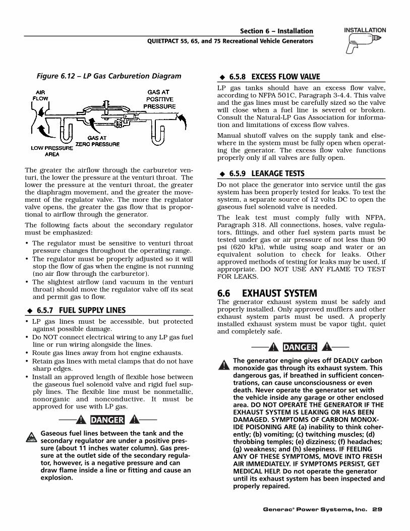
Generac® Power Systems, Inc. 29
Figure 6.12 – LP Gas Carburetion Diagram
The greater the airflow through the carburetor ven-turi, the lower the pressure at the venturi throat. Thelower the pressure at the venturi throat, the greaterthe diaphragm movement, and the greater the move-ment of the regulator valve. The more the regulatorvalve opens, the greater the gas flow that is propor-tional to airflow through the generator.
The following facts about the secondary regulatormust be emphasized:
• The regulator must be sensitive to venturi throatpressure changes throughout the operating range.
• The regulator must be properly adjusted so it willstop the flow of gas when the engine is not running(no air flow through the carburetor).
• The slightest airflow (and vacuum in the venturithroat) should move the regulator valve off its seatand permit gas to flow.
6.5.7 FUEL SUPPLY LINES• LP gas lines must be accessible, but protected
against possible damage.• Do NOT connect electrical wiring to any LP gas fuel
line or run wiring alongside the lines.• Route gas lines away from hot engine exhausts.• Retain gas lines with metal clamps that do not have
sharp edges.• Install an approved length of flexible hose between
the gaseous fuel solenoid valve and rigid fuel sup-ply lines. The flexible line must be nonmetallic,nonorganic and nonconductive. It must beapproved for use with LP gas.
Gaseous fuel lines between the tank and thesecondary regulator are under a positive pres-sure (about 11 inches water column). Gas pres-sure at the outlet side of the secondary regula-tor, however, is a negative pressure and candraw flame inside a line or fitting and cause anexplosion.
6.5.8 EXCESS FLOW VALVELP gas tanks should have an excess flow valve,according to NFPA 501C, Paragraph 3-4.4. This valveand the gas lines must be carefully sized so the valvewill close when a fuel line is severed or broken.Consult the Natural-LP Gas Association for informa-tion and limitations of excess flow valves.
Manual shutoff valves on the supply tank and else-where in the system must be fully open when operat-ing the generator. The excess flow valve functionsproperly only if all valves are fully open.
6.5.9 LEAKAGE TESTSDo not place the generator into service until the gassystem has been properly tested for leaks. To test thesystem, a separate source of 12 volts DC to open thegaseous fuel solenoid valve is needed.
The leak test must comply fully with NFPA,Paragraph 318. All connections, hoses, valve regula-tors, fittings, and other fuel system parts must betested under gas or air pressure of not less than 90psi (620 kPa), while using soap and water or anequivalent solution to check for leaks. Otherapproved methods of testing for leaks may be used, ifappropriate. DO NOT USE ANY FLAME TO TESTFOR LEAKS.
6.6 EXHAUST SYSTEMThe generator exhaust system must be safely andproperly installed. Only approved mufflers and otherexhaust system parts must be used. A properlyinstalled exhaust system must be vapor tight, quietand completely safe.
The generator engine gives off DEADLY carbonmonoxide gas through its exhaust system. Thisdangerous gas, if breathed in sufficient concen-trations, can cause unconsciousness or evendeath. Never operate the generator set withthe vehicle inside any garage or other enclosedarea. DO NOT OPERATE THE GENERATOR IF THEEXHAUST SYSTEM IS LEAKING OR HAS BEENDAMAGED. SYMPTOMS OF CARBON MONOX-IDE POISONING ARE (a) inability to think coher-ently; (b) vomiting; (c) twitching muscles; (d)throbbing temples; (e) dizziness; (f) headaches;(g) weakness; and (h) sleepiness. IF FEELINGANY OF THESE SYMPTOMS, MOVE INTO FRESHAIR IMMEDIATELY. IF SYMPTOMS PERSIST, GETMEDICAL HELP. Do not operate the generatoruntil its exhaust system has been inspected andproperly repaired.
!
DANGER
◆
◆
DANGER
◆
Section 6 – InstallationQUIETPACT 55, 65, and 75 Recreational Vehicle Generators
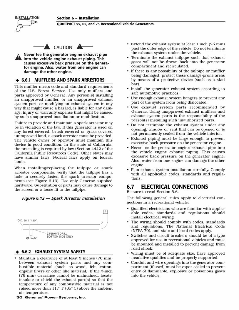
30 Generac® Power Systems, Inc.
Never tee the generator engine exhaust pipeinto the vehicle engine exhaust piping. Thiscauses excessive back pressure on the genera-tor engine. Also, water from one engine candamage the other engine.
6.6.1 MUFFLERS AND SPARK ARRESTORSThis muffler meets code and standard requirementsof the U.S. Forest Service. Use only mufflers andparts approved by Generac. Any person(s) installingan unapproved muffler, or an unapproved exhaustsystem part, or modifying an exhaust system in anyway that might cause a hazard, is liable for any dam-age, injury or warranty expense that might be causedby such unapproved installation or modification.
Failure to provide and maintain a spark arrestor maybe in violation of the law. If this generator is used onany forest covered, brush covered or grass coveredunimproved land, a spark arrestor must be provided.The vehicle owner or operator must maintain thisdevice in good condition. In the state of California,the preceding is required by law (Section 4442 of theCalifornia Public Resources Code). Other states mayhave similar laws. Federal laws apply on federallands.
When installing/replacing the tailpipe or sparkarrestor components, verify that the tailpipe has ahole to securely fasten the spark arrestor compo-nents (see Figure 6.13). Use only Generac suppliedhardware. Substitution of parts may cause damage tothe screen or a loose fit to the tailpipe.
Figure 6.13 — Spark Arrestor Installation
6.6.2 EXHAUST SYSTEM SAFETY• Maintain a clearance of at least 3 inches (76 mm)
between exhaust system parts and any com-bustible material (such as wood, felt, cotton,organic fibers or other like material). If the 3-inch(76 mm) clearance cannot be maintained, locate,insulate or shield the exhaust part(s) so that thetemperature of any combustible material is notraised more than 117° F (65° C) above the ambientair temperature.
• Extend the exhaust system at least 1 inch (25 mm)past the outer edge of the vehicle. Do not terminatethe exhaust system under the vehicle.
• Terminate the exhaust tailpipe such that exhaustgases will not be drawn back into the generatorcompartment and recirculated.
• If there is any possibility of the tailpipe or mufflerbeing damaged, protect these damage-prone areasby means of a protective device (such as a skidbar).
• Install the generator exhaust system according tosafe automotive practices.
• Use enough exhaust system hangers to prevent anypart of the system from being dislocated.
• Use exhaust system parts recommended byGenerac. Using unapproved exhaust mufflers andexhaust system parts is the responsibility of theperson(s) installing such unauthorized parts.
• Do not terminate the exhaust system under anyopening, window or vent that can be opened or isnot permanently sealed from the vehicle interior.
• Exhaust piping must be large enough to preventexcessive back pressure on the generator engine.
• Never tee the generator engine exhaust pipe intothe vehicle engine exhaust piping. This causesexcessive back pressure on the generator engine.Also, water from one engine can damage the otherengine.
• Plan exhaust system installation carefully. Complywith all applicable codes, standards and regula-tions.
6.7 ELECTRICAL CONNECTIONSBe sure to read Section 5.6.
The following general rules apply to electrical con-nections in a recreational vehicle:
• Qualified electricians who are familiar with applic-able codes, standards and regulations shouldinstall electrical wiring.
• The wiring should comply with codes, standardsand regulations. The National Electrical Code(NFPA 70), and state and local codes apply.
• Switches and circuit breakers should be of a typeapproved for use in recreational vehicles and mustbe mounted and installed to prevent damage fromroad shock.
• Wiring must be of adequate size, have approvedinsulative qualities and be properly supported.
• Conduit and wire openings into the generator com-partment (if used) must be vapor-sealed to prevententry of flammable, explosive or poisonous gasesinto the vehicle.
◆
24 [0.95"]
3.5 [9/64"] DRILLBOTTOM SIDE ONLY
O.D. 38.1 [1.50"]
◆
!
Section 6 – InstallationQUIETPACT 55, 65, and 75 Recreational Vehicle Generators
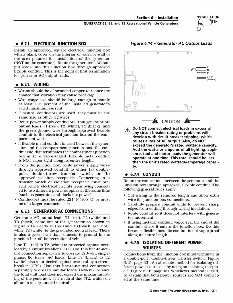
Generac® Power Systems, Inc. 31
6.7.1 ELECTRICAL JUNCTION BOXInstall an approved, square electrical junction boxwith a blank cover on the interior or exterior wall ofthe area planned for installation of the generator(NOT on the generator). Route the generator's AC out-put leads into this junction box through approvedflexible conduit. This is the point of first terminationfor generator AC output leads.
6.7.2 WIRING• Wiring should be of stranded copper to reduce the
chance that vibration may cause breakage.• Wire gauge size should be large enough to handle
at least 115 percent of the installed generator'srated maximum current.
• If neutral conductors are used, they must be thesame size as other leg wires.
• Route power supply conductors from generator ACoutput leads T1 (red), T2 (white), T3 (black) andthe green ground wire through approved flexibleconduit to the electrical junction box on the com-partment wall.
• If flexible metal conduit is used between the gener-ator and the compartment junction box, the con-duit end that terminates the compartment junctionbox must be vapor-sealed. Flexible metal conduitis NOT vapor tight along its entire length.
• From the junction box, route power supply wiresthrough approved conduit to either (a) double-pole, double-throw transfer switch, or (b)approved isolation receptacle. Connecting to atransfer switch or isolation receptacle must pre-vent vehicle electrical circuits from being connect-ed to two different power supplies at the same time(such as generator and dockside power).
• Conductors must be rated 221° F (105° C) or mustbe of a larger conductor size.
6.7.3 GENERATOR AC CONNECTIONSGenerator AC output leads T1 (red), T2 (white) andT3 (black) come out of the generator as shown in Figure 6.14. Leads T1 (red) and T3 (black) are “hot,”while T2 (white) is the grounded neutral lead. Thereis also a green lead that connects to ground in thejunction box of the recreational vehicle.
Line T1 (red) to T2 (white) is protected against over-load by a circuit breaker (CB1). Use this line-to-neu-tral connection separately to operate 120-volt, single-phase, 60 Hertz, AC loads. Line T3 (black) to T2(white) also is protected against overload by a circuitbreaker (CB2). Use this line-to-neutral connectionseparately to operate similar loads. However, be surethe total unit load does not exceed the maximum rat-ing of the generator. The neutral line (T2, white) onall units is a grounded neutral.
Figure 6.14 – Generator AC Output Leads
Do NOT connect electrical loads in excess ofany circuit breaker rating or problems willdevelop with circuit breaker tripping, whichcauses a loss of AC output. Also, do NOTexceed the generator's rated wattage capacity.Add the watts or amperes of all lighting, appli-ance, tool and motor loads the generator willoperate at one time. This total should be lessthan the unit's rated wattage/amperage capaci-ty.
6.7.4 CONDUITRoute the connections between the generator and thejunction box through approved, flexible conduit. Thefollowing general rules apply:
• Cut wiring to the required length and allow extrawire for junction box connections.
• Carefully prepare conduit ends to prevent sharpedges from cutting through wiring insulation.
• Route conduit so it does not interfere with genera-tor movement.
• If using metallic conduit, vapor seal the end of theconduit where it enters the junction box. Do thisbecause flexible metallic conduit is not vaporproofalong its entire length.
6.7.5 ISOLATING DIFFERENT POWERSOURCES
Connections from the junction box must terminate ina double-pole, double-throw transfer switch (Figure6.15, page 33). An alternate method for isolating dif-ferent power sources is by using an isolating recepta-cle (Figure 6.16, page 33). Whichever method is used,be certain that both power sources are NOT connect-ed at the same time.
◆
◆
T3T2T1
Green(Ground)
◆
◆
◆
Section 6 – InstallationQUIETPACT 55, 65, and 75 Recreational Vehicle Generators
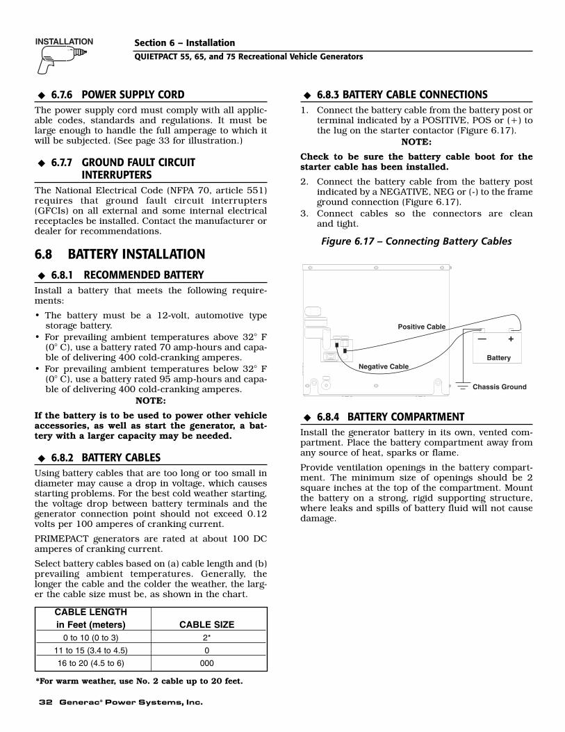
32 Generac® Power Systems, Inc.
Section 6 – InstallationQUIETPACT 55, 65, and 75 Recreational Vehicle Generators
6.7.6 POWER SUPPLY CORDThe power supply cord must comply with all applic-able codes, standards and regulations. It must belarge enough to handle the full amperage to which itwill be subjected. (See page 33 for illustration.)
6.7.7 GROUND FAULT CIRCUIT INTERRUPTERS
The National Electrical Code (NFPA 70, article 551)requires that ground fault circuit interrupters(GFCIs) on all external and some internal electricalreceptacles be installed. Contact the manufacturer ordealer for recommendations.
6.8 BATTERY INSTALLATION6.8.1 RECOMMENDED BATTERY
Install a battery that meets the following require-ments:
• The battery must be a 12-volt, automotive type storage battery.
• For prevailing ambient temperatures above 32° F(0° C), use a battery rated 70 amp-hours and capa-ble of delivering 400 cold-cranking amperes.
• For prevailing ambient temperatures below 32° F(0° C), use a battery rated 95 amp-hours and capa-ble of delivering 400 cold-cranking amperes.
NOTE:
If the battery is to be used to power other vehicleaccessories, as well as start the generator, a bat-tery with a larger capacity may be needed.
6.8.2 BATTERY CABLESUsing battery cables that are too long or too small indiameter may cause a drop in voltage, which causesstarting problems. For the best cold weather starting,the voltage drop between battery terminals and thegenerator connection point should not exceed 0.12volts per 100 amperes of cranking current.
PRIMEPACT generators are rated at about 100 DCamperes of cranking current.
Select battery cables based on (a) cable length and (b)prevailing ambient temperatures. Generally, thelonger the cable and the colder the weather, the larg-er the cable size must be, as shown in the chart.
6.8.3 BATTERY CABLE CONNECTIONS1. Connect the battery cable from the battery post or
terminal indicated by a POSITIVE, POS or (+) tothe lug on the starter contactor (Figure 6.17).
NOTE:
Check to be sure the battery cable boot for thestarter cable has been installed.
2. Connect the battery cable from the battery postindicated by a NEGATIVE, NEG or (-) to the frameground connection (Figure 6.17).
3. Connect cables so the connectors are clean and tight.
Figure 6.17 – Connecting Battery Cables
6.8.4 BATTERY COMPARTMENTInstall the generator battery in its own, vented com-partment. Place the battery compartment away fromany source of heat, sparks or flame.
Provide ventilation openings in the battery compart-ment. The minimum size of openings should be 2square inches at the top of the compartment. Mountthe battery on a strong, rigid supporting structure,where leaks and spills of battery fluid will not causedamage.
◆
Positive Cable
Negative CableBattery
— +
Chassis Ground
◆
◆
◆
◆
◆
CABLE LENGTHin Feet (meters) CABLE SIZE
0 to 10 (0 to 3) 2*
11 to 15 (3.4 to 4.5) 0
16 to 20 (4.5 to 6) 000
*For warm weather, use No. 2 cable up to 20 feet.
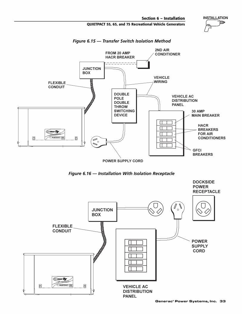
Generac® Power Systems, Inc. 33
Section 6 – InstallationQUIETPACT 55, 65, and 75 Recreational Vehicle Generators
Figure 6.15 — Transfer Switch Isolation Method
POWERED BY GUARDIAN 760cc OHVI V-TWIN
QUIETPACTINDUSTRIAL
55G
Figure 6.16 — Installation With Isolation Receptacle
POWERED BY GUARDIAN 760cc OHVI V-TWIN
QUIETPACTINDUSTRIAL
55G

34 Generac® Power Systems, Inc.
6.9 OPTIONAL ACCESSORIESA plug-in receptacle (Figure 6.18) is provided on thegenerator set, above the muffler enclosure. Use thisreceptacle to connect an optional remote-mountedstart/stop panel to the generator. Installation of sucha panel will permit starting and stopping the genera-tor engine from any convenient location inside thevehicle.
Figure 6.18 – Remote Panel Plug-in Receptacle
6.9.1 REMOTE PANEL MODELSThe remote panels mount a rocker type start/stopswitch, a “Generator Run” advisory lamp and anhourmeter. The hourmeter should be used in con-junction with the maintenance operations found inPart I of this manual.
• Part number 0F0429 includes the remote paneland a 10 foot long, 6 wire harness.
• Part number 0F0430 includes the remote paneland a 30 foot long, 6 wire harness.
7.1 POST INSTALLATION TESTSThe air-cooled generator set was factory tested andadjusted. It should not be necessary to adjust the unitany further except under special circumstances.
Do not make any unnecessary adjustments.Factory settings are correct for most applica-tions. When making adjustments, however, becareful to avoid overspeeding the engine.
7.2 BEFORE INITIAL START-UPBefore starting, complete the following:
1. Check the engine crankcase oil level and, if nec-essary, fill to the dipstick “FULL” mark (cross-hatched area) with the recommended oil. Do notfill above the FULL mark.
2. Check the fuel supply. Gas fuel lines must havebeen properly purged and leak tested in accor-dance with applicable fuel codes. All fuel shutoffvalves in the fuel supply lines must be open.
If a liquid propane (LP) gas fuel system hasbeen installed, it must be properly tested forleaks before operating the system in compli-ance with ANSI A119.2/NFPA 501C. No leakageis permitted. Be sure that gasoline fuel vaporsdo not enter the vehicle interior.
7.3 INITIAL STARTWhen certain that the unit has been properlyinstalled and prepared for use, start the engine as fol-lows:
1. Turn off all electrical loads. Do this by setting thegenerator’s main circuit breakers to their “OFF”(or open) position.
2. Refer to Part I, Section 2.5, “Starting theGenerator”, for cranking and starting instruc-tions. The engine may require more cranking forinitial starting since the fuel lines have to beprimed (use of the primer switch will shorten thistime).
3. Let the engine warm up for about five minutes toallow internal temperatures to stabilize.
4. Carefully inspect the engine/generator for fuel, oiland exhaust system leaks. Before proceeding tothe next step, correct any leakage immediately.
5. When all tests and adjustments at no-load arecompleted, apply electrical loads and check forproper operation under load. See Section 7.4.Run the unit at least 30 minutes with loadsapplied.
6. Turn off all electrical loads by setting the genera-tor’s main circuit breakers to their “OFF” (oropen) position.
7. Let the unit run at no-load for a few minutes tostabilize internal engine/generator temperatures.Then, shut down the engine.
NOTE:
The generator set was thoroughly tested andadjusted at the factory before shipping. No addi-tional adjustment should be necessary. Only qual-ified service technicians who have been trainedshould perform adjustments outlined in this man-ual.
!
DANGER
!
◆
12.00"
14
0
17
15
18
14A
1
3
2
5
4
6
0
14
17
18
14A
15
1517
14A18
140
No.WIRE WIRE
COLOR
RED
YELLOWORANGE
WHITE
BLUEBROWN
12.0 (305)
LENGTH (mm)
12.0 (305)12.0 (305)12.0 (305)12.0 (305)12.0 (305)
FUNCTION
GROUNDENGINE RUN SIGNAL
12 VDCSTARTSTOPPRIME
P/N: 0D9099-B
Section 7 – Post InstallationQUIETPACT 55, 65, and 75 Recreational Vehicle Generators

Generac® Power Systems, Inc. 35
7.4 TESTING UNDER LOADApply electrical loads equal to about 75 to 100 per-cent of the unit's rated wattage/amperage capacity.
Let the unit run at least 30 minutes with loadapplied. During this part of the test, check that theunit is not running excessively hot and that adequatecooling airflow is available. Do not allow the unit tooverheat during prolonged operation.
NOTE:
The generator engine is equipped with a high tem-perature switch. The switch has normally open(N.O.) contacts. When the engine temperature istoo high, switch contacts close, and the engineshuts down automatically.
GENERAC RECOMMENDS THAT THE GENERA-TOR BE TESTED FOR ADEQUATE COOLING.
7.5 INSTALLATION CHECKLISTLOCATION AND SUPPORT
❑ Generator is properly located.
❑ Generator is properly supported.
❑ Generator is properly restrained.
GENERATOR COMPARTMENT❑ Compartment construction is proper.
❑ Holes/Openings are vapor-sealed.
❑ Compartment size is correct.
❑ Compartment is vapor-sealed.
❑ Sound insulation is correct.
❑ Floor cutouts are properly completed.
COOLING AND VENTILATING AIR❑ Airflow is adequate.
❑ Air inlet opening is correct.
❑ Compensate for restrictions.
❑ Check that installation has been tested.
GASOLINE FUEL SYSTEM❑ Fuel tank complies with all applicable codes.
❑ Fuel system is properly installed and checked for leaks.
OPTIONAL LP GAS FUEL SYSTEM❑ Fuel system is properly installed and checked
for leaks.
❑ Pressure at regulator inlet is correct.
❑ Rated flow of primary regulator is correct.
❑ All parts are properly installed.
❑ Fuel system is properly tested/adjusted.
EXHAUST SYSTEM❑ Exhaust system complies with all applicable
codes.
❑ Exhaust system is properly and safely installed.
ELECTRICAL CONNECTIONS❑ Connections comply with local code requirements
and all National Electrical Codes.
❑ Junction box is properly installed.
❑ Wiring meets all standards.
❑ All connections are correct.
❑ Conduit is properly installed and sealed.
❑ Generator is properly bonded to the vehicle.
BATTERY INSTALLATION❑ Recommended battery is installed.
❑ Recommended cables are installed.
❑ Cables are clean and tight.
❑ Cables are connected properly.
❑ Proper ventilation is provided.
❑ Terminals are coated with anti-corrosion grease,and terminal covers are positioned.
OPTIONAL ACCESSORIES❑ Check that remote start/stop panels (if used) are
installed properly.
❑ Check that hourmeter kit (if used) is installed properly.
❑ Check that any other options and accessories (ifused) are installed properly.
POST INSTALLATION TESTS❑ Check that all tests are completed properly.
◆
◆
◆
◆
◆
◆
◆
◆
◆
◆
Section 7 – Post InstallationQUIETPACT 55, 65, and 75 Recreational Vehicle Generators
DATE OF INSTALLATION ____________________________________________________
NAME OF INSTALLER ______________________________________________________
SIGNATURE OF INSTALLER ________________________________________________

36 Generac® Power Systems, Inc.
Section 8 – TroubleshootingQUIETPACT 55, 65, and 75 Recreational Vehicle Generators
8.1 TROUBLESHOOTING GUIDE
PROBLEM CAUSE CORRECTIONEngine won’t crank. 1. 7.5 amp fuse blown. 1. Replace blown fuse.
2. Loose, or corroded or defective 2. Tighten, clean or replace,battery cable(s). as necessary.
3. Battery is discharged or defective. 3. Recharge or replace battery.4. Defective Start/Stop switch. 4. Replace switch.5. Defective starter contactor. 5. Replace starter contactor.6. Defective starter motor. 6. Replace starter motor.7. Defective Engine Control Board 7. Contact an authorized service dealer.
Engine cranks, won't start. 1. Out of fuel. 1. Refill fuel tank.2. Fuel shutoff valve is closed. 2. Open fuel shutoff valve(s).3. Fuel pump not operating. 3. Repair or replace pump.4. Automatic choke not operating properly. 4. Repair, replace or adjust.5. Engine is flooded. 5. Wait 5-10 minutes; try again.6. Fuel filter is clogged. 6. Replace filter if clogged.7. Engine spark plugs defective. 7. Clean, regap or replace as needed.8. Bad ignition magneto on engine. 8. Replace if defective.9. Bad carburetor. 9. Adjust, repair or replace.10. Dirty air cleaner. 10. Clean or replace as needed.
Engine starts hard, runs rough. 1. Dirty engine air cleaner. 1. Clean or replace as needed.2. Automatic choke is sticking. 2. Free choke linkage as needed.3. Defective spark plugs. 3. Clean, regap or replace.4. Defective ignition magneto. 4. Replace it if defective.
Engine starts, then shuts down. 1. Engine oil level is low. 1. Add oil as needed.2. Bad low oil pressure switch. 2. Replace, if bad.3. Defective high temp switch. 3. Replace, if bad.4. Water in fuel. 4. Drain fuel tank and refill.5. Defective remote harness. 5. Disconnect remote harness. Contact
authorised service facility.
No AC output voltage. 1. Main breaker(s) open. 1. Close main breaker(s).2. Transfer switch (if so equipped) is 2. Reset transfer switch.
set to wrong position.3. Failure in vehicle electrical system. 3. See vehicle manual.4. Generator component failure. 4. Contact an authorized service facility.

Generac® Power Systems, Inc. 37
Section 9 – NotesQUIETPACT 55, 65, and 75 Recreational Vehicle Generators

38 Generac® Power Systems, Inc.
Section 10 — Electrical Data
QUIETPACT 55, 65, and 75 Recreational Vehicle GeneratorsElectrical Schematic - V-Twin – Drawing No. 0E1057-E
SW1
SCR
BLK
T2
NEUTRAL CONNECTIONBY CUSTOMER
GREEN
WHITE
0F
0N
22P44
0K
0N
120V 35A - QP75120V 30A - QP55 & QP65
REGULATORVOLTAGE
ELECTRONIC
FIELD120V 20A - QP55
120V 35A - QP75120V 30A - QP65
DPE WINDING
CB3
2
2A
22S
6
4
4
11S
14
15
0N
15
14A
15
14
POWER WINDING
R1
55
77
14A15
66
BCR
66
J1-13
J1-14
J1-15
J1-10
J1-12
J1-11
J1-6
J1-8
J1-7
J1-9
J1-3
J1-4
J1-5
18
18
66
85
0
66
17
17
4
16
18A
13
RED
15
15
F1
SW2
J3
J2
13
14A
14
PCB
J1-2
J1-1
SC
14SCR
RED
16
16
56
90
16
FP
SC 0
SM
BATTERY
LOP - SWITCH, LOW OIL PRESSURE (CLOSES ON LOW PRESSURE)
HTO - SWITCH, HIGH TEMP. OIL (CLOSES ON HIGH TEMP.)
L1 - LIGHT, RUN (OPTIONAL)
PCB - ENGINE CONTROLLER
SC - STARTER CONTACTORR1 - RESISTOR, 1 OHM 25W
GT - TERMINAL, GROUNDFS - FUEL SOLENOID
SM - STARTER MOTORSW1 - SWITCH, START/STOPSW2 - SWITCH FUEL PRIMER
TC - TERMINAL, CONN. 4-TABSP2 - SPARK PLUG #2 CYL.SP1 - SPARK PLUG #1 CYL.
IM2 - IGNITION MAGNETO - #2 CYL.
SCR - STARTER CONTACTOR RELAY
IM1 - IGNITION MAGNETO - #1 CYL.
FP - FUEL PUMP-OR-LPG SHUT OFF VALVE
HM - METER, HOUR (OPTIONAL)
- CONNECTOR
F1 - FUSE, 7.5ACS - CHOKE SOLENOID (GASOLINE MODELS ONLY)CH - CHOKE HEATER (GASOLINE MODELS ONLY)
CB1 - CIRCUIT BREAKER, 30A (QP55 & QP65 MODELS)
CIRCUIT BREAKER, 3.0A (QP65 & QP75 MODELS)CB3 - CIRCUIT BREAKER, 2.5A (QP55 MODEL)
CB2 - CIRCUIT BREAKER, 20A (QP55 MODEL)
BCR - BATTERY CHARGE RECTIFIER
LEGEND
CIRCUIT BREAKER, 35A (QP75 MODEL)
CIRCUIT BREAKER, 35A (QP75 MODEL) CIRCUIT BREAKER, 30A (QP65 MODEL)
REMOTE PANEL(OPTIONAL)
BLACK
T1
RED
BLACK
T3
REDCB2
11P
CB1
FUELPRIME
5
OR
ANG
E
2 217
14A
334
14
1518
L1
HM
78
3
54
6
7
BLU
E
8
4
5
34
6
SP1
85
4
170I
85
(START)
(STOP)
IM1
IM2
0
REMOTEPANEL
CONNECTOR
1
0LOP
1
SP2
0B
HTO
YE
LLO
W
17
RED
BR
OW
N
18 14
WH
ITE
0
CS
0
CH
FS 0
0
0
0
0
18A

Generac® Power Systems, Inc. 39
Section 10 — Electrical Data
QUIETPACT 55, 65, and 75 Recreational Vehicle GeneratorsElectrical Schematic - V-Twin – Drawing No. 0E1057-E
0
CONN. 2PIN#
0
90
14
14 CH
18A
90
85
LOP
CS
0
18
RE
D
18
85
17
18A
85
PCB J1-7
J1-9
J1-12J1-11J1-10
J1-8
J1-15J1-14J1-13
J1-2
J1-5J1-4J1-3
J1-1
J2
J1-6
J3
18
1
FS
14
2
3
1818A
18 CONN. 1PIN#
0
0
FP
90
14
2
1
2A
2
17
18
4
16
CB3
66
0
56
14
15
90
0
90
16 56
IM2
18A
HTO
SP1
0
85
SP2
0
13
18A
14A15
18
15
0
66
77
1415
14
15
0
0
2
14
14A
14
F1
66
BCR
15
142A
13
17
4
15
2A
17
00
15
0
SW1SW2
TC
0K
0
00
0
0B
17
18
0
GT0
0I
0
42
0
SCR
A
16
B
13
16
0
BATTERYTO 12V
11S
13
0
1316
(-) (+)
0K
4
22S
4
2A
6 2A
SC
REGULATORVOLTAGE
ELECTRONIC
SM
GREEN
BLACK
14A
CB2
BLACK
11P
RED
T3 T1
WHITE
WHITE
BY CUSTOMERNEUTRAL CONNECTIONAC CONNECTIONCUSTOMER
15
14A
14A
0F
22P
0
0F
CB1
140
RED
33
0F
17
0
GT
T2T2
11P
33
44
77
22S
11S
3366
RED
22P11P
4455
6
2
R1
CONNECTOR
17
14
18
REMOTEPANEL
3
4
7
5
6
0I
55
0N
1
2 8
14A
15
15
CLOSEST TO BEARING
4
FIELD
STATOR

40 Generac® Power Systems, Inc.
1
324
6
34
79
8
5
10
11
12
133
21
1514
32
1617
201819
23
4
232221
2526
2728
4530
10
31
3233
34
35
3637
38
39
40
414243
44
46
52
47
48
49 50 51 26 52
57
56
55
5354
50
53 58
5960
61
62
A
"A
TO CARB.
"B"
"B"
Section 11 — Exploded Views and Parts ListsQUIETPACT 55, 65, and 75 Recreational Vehicle GeneratorsBase & Pulley – Drawing No. 0E1323-C

Generac® Power Systems, Inc. 41
Section 11 — Exploded Views and Parts ListsQUIETPACT 55, 65, and 75 Recreational Vehicle Generators
Base & Pulley – Drawing No. 0E1323-C
ITEM PART NO. QTY. DESCRIPTION
1 0E0196 1 FRAME, 760 ENGINE2 022129 12 WASHER LOCK M8-5/163 022145 15 WASHER FLAT 5/16-M8 ZINC4 022259 6 NUT HEX 5/16-18 STEEL5 0C7758 4 VIB MNT 1.5 X 1.38 X 5/16-186 0C3168 1 WASHER LOCK SPECIAL 5/167 0C2417 1 EARTH STRAP8 077603 2 SCREW HHC 5/16-18 X 3.5 SPC9 0E0588 1 SPACER, SAFETY BOLT .375 I.D.
10 029451 1.5 FT. TAPE ELEC UL FOAM 1/8 X ½11 0D8912 1 DUCT, AIR OUT12 0E0571 2 GASKET,AIR OUT DUCT13 0D8911 1 BRACKET, MUFFLER SUPPORT14 043107 7 SCREW HHC M8-1.25 X 25 G8.815 0D9021 1 MUFFLER, GTV760 RV16 096289 1 CLAMP, EXHAUST 1.25"17 0D8940 1 MANIFOLD, EXHAUST18 070006 4 WASHER LOCK M8 SS19 070008 4 WASHER FLAT M8 SS20 040976 4 SCREW SHC M8-1.25 X 20 G12.921 056893 5 SCREW CRIMPTITE 10-24 X ½22 023897 5 WASHER FLAT #10 ZINC23 0E1078 1 GASKET, EXH BASE, GTV760 RV24 0C4138 2 GASKET,EXHAUST PORT25 043116 3 SCREW HHC M6-1.0 X 12 G8.8 (5.5 KW
ONLY)26 022097 4 WASHER LOCK M6-1/4 (5.5 KW ONLY)
022097 1 WASHER LOCK M6-1/4 (6.5 & 7.5 KWONLY)
27 022473 3 WASHER FLAT 1/4-M6 ZINC (5.5 KWONLY)
28 0C1751 1 FAN NYLON 7" DIA (5.5 KW ONLY)29 0C1753B 1 PULLEY, ALTERNATOR 2200 RPM (5.5 KW
ONLY)073106B 1 PULLEY, ALTERNATOR 2500 RPM (6.5 &
7.5 KW ONLY)30 075224A 1 PULLEY, ENGINE 2100 RPM (5.5 KW
ONLY)075224B 1 PULLEY, ENGINE 2500 RPM (6.5 & 7.5 KW
ONLY)
ITEM PART NO. QTY. DESCRIPTION
31 0E0586 1 GASKET, BOTTOM AIR OUT QPRV32 0D7176 4 WASHER SELF LOCKING 1"DIA 12GA33 0E1334 1 SCREEN, BOTTOM AIR OUT34 0D8824 1 TRAY, V-TWIN RV35 081105 2 NUT FLG 5/16-18 LOCK36 073118 1 SCREW HHC 3/8-24 X 2-1/4 G837 046526 1 WASHER LOCK M1038 022131 1 WASHER FLAT 3/8-M10 ZINC39 0C2824 7 SCREW TAP-R #10-32 X 9/140 0E1077 1 BLOWER HOUSING GTV760 RV41 042633 1 SCREW HHC 3/8-24 X 1 G542 022237 1 WASHER LOCK 3/843 049451 1 WASHER FLAT .406ID X 1.62OD44 0C1441 1 SET,BLOWER HOUSING GASKET45 0C1112 1 BELT,V-RIB 4LX42.5"46 023484E 1 BUSHING SNAP (GASOLINE ONLY)
0E1534 1 PLUG PLASTIC 0.687" (LP ONLY)47 0D7530 1 STUD, M6-1.0 OFFSET48 0D9723 1 ELEMENT AIR FILTER49 0D4511 1 PRECLEANER,AIR GTH990 GASOLINE50 0D8981 2 FILTER GASKET RV (GASOLINE ONLY)
0D8981 1 FILTER GASKET RV (LP ONLY)51 0D8451 1 WASHER FLAT .281"ID X 1.25"OD52 087680 2 NUT WING M6-1.053 0D3700 3 NUT FLANGE M6-1.0 NYLOK (GASOLINE
ONLY)0D3700 1 NUT FLANGE M6-1.0 NYLOK (LP ONLY)
54 087769 1 FILTER FUEL (GASOLINE ONLY)55 0E0570 1 ASSEMBLY,NON SHTOFF FUEL PUMP
(GASOLINE ONLY)56 0D9919 1 ASSEMBLY, RV V-TWIN FUEL LINE (
GASOLINE ONLY)57 0E1330 1 GROMMET, 38.1 DIA. CROSS SLIT
(GASOLINE ONLY)0E1534A 1 PLUG PLASTIC 1.50" (LP ONLY)
58 0A1658 1 WASHER LOCK SPECIAL 1/4"59 0D5133 1 SCREEN, SPARK ARRESTOR60 0D5133A 1 RETAINER, SPARK ARREST SCREEN61 045764 1 SCREW HHTT M4-0.7 X 8 BP62 0E1078A 1 GASKET, EXHAUST BASE
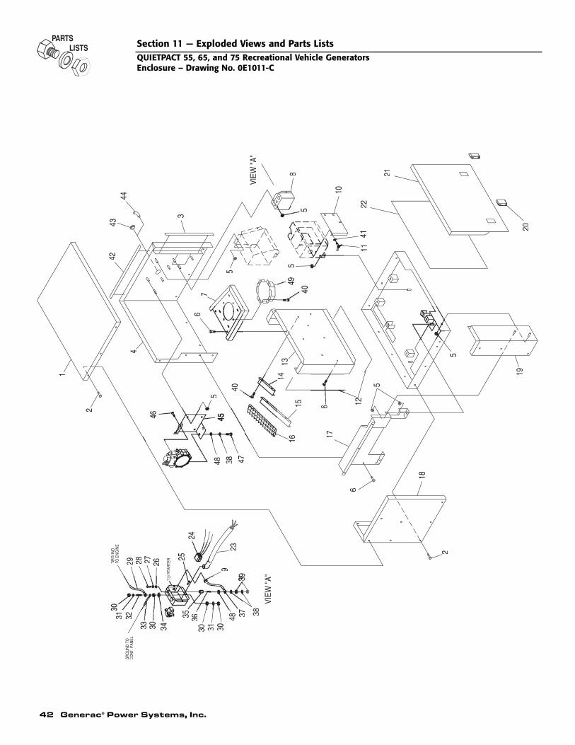
42 Generac® Power Systems, Inc.
11
2
CO
NT.
PAN
ELG
RO
UN
D T
O
VIEW
"A"
48 3837
30313033
35 36
3
3231
23
29 28 27 26TO E
NG
INE
GR
OU
ND
O S
TAR
TER
9
24
18
612
19
5
540
48 38 47
1716
615
5
2
1 1413
4
76
5
5
42
10
20
4122
21
VIEW
"A"
3
4344
8
Section 11 — Exploded Views and Parts ListsQUIETPACT 55, 65, and 75 Recreational Vehicle GeneratorsEnclosure – Drawing No. 0E1011-C

Generac® Power Systems, Inc. 43
ITEM PART NO. QTY. DESCRIPTION
1 0D8827 1 PANEL, ENCLOSURE ROOF2 0A7215 22 SCREW SW 1/4-20X5/8 N WA JS5003 029451 11.5 FT. TAPE ELEC UL FOAM 1/8 X 1/2"4 0D8825 1 PANEL, SIDE AND BACK ENCLOSURE5 0D3700 14 NUT FLANGE M6-1.0 NYLOK (GASOLINE ONLY)
0D3700 17 NUT FLANGE M6-1.0 NYLOK (LP ONLY)6 090388 8 SCREW HHTT M6-1.0 X 12 YC7 0D8979 1 PANEL, AIR IN DUCT BASE8 0D8960 1 PANEL, CUSTOMER CONNECTION9 023484D 1 BUSHING SNAP SB-875-11
10 0E0594 1 COVER, RV AIR CLEANER BOX11 064113 1 STUD WINGNUT M6-1.0 X 20MM NY12 0E0575 1 FOAM SEALING STRIP 1" X 12FT13 0D8980 1 PANEL, AIR IN DUCT BACK14 0E1376 1 BAFFLE, V-TWIN RV SHORT15 0E1377 1 BAFFLE, V-TWIN RV LONG16 0D8628 3.5 FOAM, AIR OUT COMPARTMENT17 0D8910 1 PANEL, MUFFLER SHIELD18 0D8826 1 PANEL, ENCLOSURE SIDE19 0D9162 1 PANEL, FRONT & SIDE ENCLOSURE20 0C5644 2 SLIDE LATCH,FLUSH21 0D8828 1 PANEL, ENCLOSURE DOOR22 0E0585 1 FOAM PANEL, DOOR 1/2"THK QP RV23 0E1486 1 HARNESS, AC OUTPUT (5.5, 6.5, & 7.5 KW ONLY)
0E1774 1 HARNESS, AC OUTPUT (5.0 & 7.0 KW-50 Hz ONLY)24 0D9099 1 CUST. CONN. 4KW RV REMOTE25 074908 4 SCREW HHTT M5-0.8 X 10 BP26 022473 1 WASHER FLAT 1/4-M6 ZINC27 022097 1 WASHER LOCK M6-1/428 022507 1 SCREW HHC 1/4-20 X 1/2 G529 0742600149 1 WIRE ASM. BATT. (NEG.) QP RV30 0C7968 4 NUT HEX JAM 3/8-16 BRASS31 022237 2 WASHER LOCK 3/832 0C7423 1 STUD 3/8-16 X 2-1/4 BRASS33 0742600151 1 GND WIRE C/PNL TO STUD V-T RV34 0A4456 1 WASHER LOCK SPECIAL 3/835 0D8502 1 NEUTRAL CONNETCTOR UL36 0E0593 1 STUD, 1/4-20 TO 5/16-1837 0742600148 1 WIRE ASM BATT. (POS.) QP RV38 022129 2 WASHER LOCK M8-5/16 (GASOLINE ONLY)
022129 4 WASHER LOCK M8-5/16 (LP ONLY)39 022259 2 NUT HEX 5/16-18 STEEL40 045756 8 SCREW HHTT M6-1.0 X 10 YC41 0A2115 1 WASHER NYLON .25042 029451A 6.5 FT. TAPE, 1/2" X 1/16" CLOSED CELL43 0E1534A 1 PLUG PLASTIC 1.50" (GASOLINE ONLY)44 0A5606 1 ELBOW 90DEG 3/8X3/4 (LP ONLY)45 0E1528 1 BRACKET, LP REGULATOR MOUNTING (LP ONLY)46 0A1495 2 SCREW HHTT M4-0.7 X 10 BP (LP ONLY)47 039253 2 SCREW HHC M8-1.25 X 20 G8.8 (LP ONLY)48 022145 1 WASHER FLAT 5/16-M8 ZINC (GASOLINE ONLY)
022145 3 WASHER FLAT 5/16-M8 ZINC (LP ONLY)49 0D8979A 1 PANEL, AIR IN DUCT
Section 11 — Exploded Views and Parts ListsQUIETPACT 55, 65, and 75 Recreational Vehicle Generators
Enclosure – Drawing No. 0E1011-C
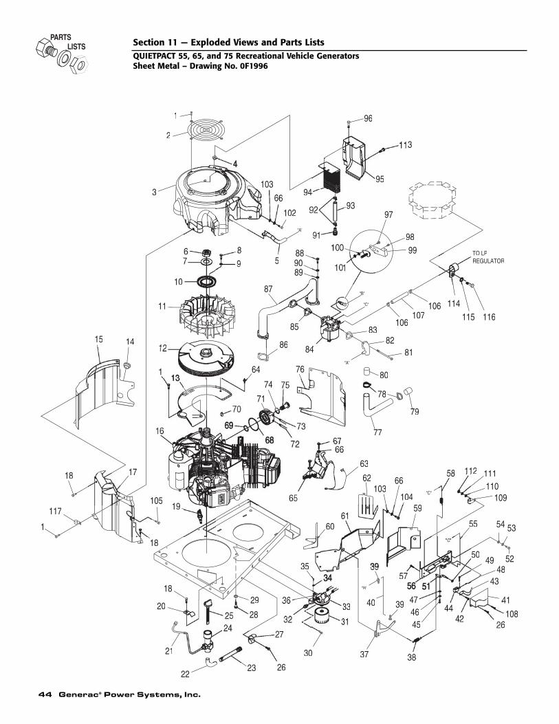
44 Generac® Power Systems, Inc.
110111
116
REGULATORTO LP
49
43
22
18
117
1
18
21
20
17
18
10519
2
15 1412
11
10
7
3
1
67
31
23
29
28
26
36
27
30
35
60
59
474645
33
37
40 39
103
6
62
63
57
66
104
58
55
50
112
103
87
74
64
8
86
85
84
889089
102
5
69
94
3
107
79
78
77
83
80
106
8281
95
9397
9998
114106115
96
1086
53
48
54
109
"B"
"A"A
"B"
"A"
"C"
Section 11 — Exploded Views and Parts ListsQUIETPACT 55, 65, and 75 Recreational Vehicle GeneratorsSheet Metal – Drawing No. 0F1996

Generac® Power Systems, Inc. 45
ITEM PART NO. QTY. DESCRIPTION
1 045756 15 SCREW HHTT M6-1.0 X 10 YC2 0D1131 1 GUARD,FAN 12KW HSB3 0F1169G 1 HOUSING, BLOWER V-TWIN RV4 0C9763 4 NUT,GROMMET 1/4 PLUG5 0D9782A 1 HOSE, BREATHER6 0C3034 1 NUT HEX M24-2.0 G8 YEL CHR7 0C3033 1 WASHER,BELLEVILLE 25MM BOLT8 051754 2 SCREW HHC M8-1.25 X 12 G8.89 0A5992 2 WASHER SHAKEPROOF INT M8 SS
10 0C3032 1 PLATE, FAN 11 0C3031 1 FAN NYLON 12 0C3725A 1 FLYWHEEL ASSY 13 0F1170A 1 PLATE,BACKING WITH OIL COOL14 023484S 1 BUSHING SNAP15 0D9679A 1 WRAP, CRANKCASE RV SPCC16 0E8775 1 VERTICAL SHAFT RV ENGINE17 0F1167A 1 WRAP, CYL 1 RV SPCC18 056893 13 SCREW CRIMPTITE 10-24 X ½19 0E7585 2 SPARK PLUG20 0E0998 1 CLAMP VINYL 9.5 O.D. TUBE21 0D8384 1 TUBE, OIL DRAIN & CHECK22 043790A 1 BARBED EL 90 3/8NPT X 3/8 VS23 0D3083 1 ASSEMBLY, OIL DRAIN HOSE24 0E0361A 1 OIL DRAIN / DIPSTICK TUBE VTW25 0E0393 1 ASSEMBLY, CAP & DIP STICK26 0C2824 2 SCREW TAP-R #10-32 X 9/16 (GASOLINE
ONLY)0C2824 1 SCREW TAP-R #10-32 X 9/16 (LP ONLY)
27 065852 1 SPRING CLIP HOLDER .37-.6228 075246 4 SCREW HHTT 3/8-16 X 1-1/4 CZ29 0A4456 1 WASHER LOCK SPECIAL 3/830 0A2311 2 SCREW SWAGE 1/4-20 X 1 Z/YC31 070185B 1 OIL FILTER 32 0A8584 1 SWITCH OIL PRESSURE HOBBS33 0A5360 1 SUPPORT OIL FLTR,FLARE34 043182 2 WASHER LOCK M335 0C1085 2 SCREW PPHM M3-0.5 X 836 0E1497 1 SWITCH, OIL HIGH TEMP (GASOLINE
ONLY)075281 1 SWITCH, OIL HIGH TEMP (LP ONLY)
37 0D9399 1 ASSEMBLY, GOVERNOR LEVER38 0D9513 1 SPRING, GOV.(5.5 KW & 5.0 KW-50HZ
ONLY)0E1498 1 SPRING, GOV.(6.5/7.5 KW & 7.0 KW-50HZ
ONLY)39 0D1366 2 BUSHING, GOVERNOR ROD40 0D9395 1 ROD, GOVERNOR41 077075 1 BOOT CHOKE SOLENOID (GASOLINE
ONLY)42 0A7094 2 RHMS 4-40 X 1/4 SEMS (GASOLINE ONLY)43 0D8590 1 ASSY, BI-METAL/HEATER (GASOLINE
ONLY)44 0D8591 1 SOLENOID, CHOKE (GASOLINE ONLY)45 045770 1 SCREW HHC M5-0.8 X 10 G8.846 049226 1 WASHER LOCK M547 051713 1 WASHER FLAT M548 0D9402 1 LINKAGE, CHOKE (GASOLINE ONLY)49 077091 1 COTTER PIN (GASOLINE ONLY)50 082025 1 NUT LOCK HEX M5-0.8 SS NYL INS51 0E1247 1 ASSEMBLY, GOV. ADJUSTMENT52 055173 2 SCREW HHC M8-1.25 X 20 G10.953 022129 2 WASHER LOCK M8-5/1654 022145 2 WASHER FLAT 5/16-M8 ZINC55 0D9403 1 LINKAGE CHOKE BELLCRANK/CARB56 0E1246 1 ASSEM., CHOKE BRACKET (GASOLINE
ONLY)
ITEM PART NO. QTY. DESCRIPTION
0D9400 1 BRACKET, CHOKE (LP ONLY)57 0A7095 2 RHMS 4-40 X 5/16SEMS58 0D9404 1 SPRING, CHOKE RETURN59 0D9801A 1 WRAP, VALLEY UPPER SPCC60 0C3018A 1 WRAPPER,UPR #1 W/ M8 WELD NUT61 0D9680A 1 WRAP, VALLEY RV SPCC62 0D1143A 1 WRAPPER,UPR #2 W/ M8 WELD NUT63 0F1177 1 ASSY, GROUNDING WIRE64 0E4997 1 ASSY,GROUND WIRE CONNECTOR65 0F1409 2 ASSY, IGN COIL W/DIODE NO ADV66 022097 8 WASHER LOCK M6-1/467 092079 4 SCREW HHTT M6-1.0 X 25 BP68 0C1546 1 O-RING 59.92 X 66.98 X 3.53MM69 0C1547 1 O-RING 21.89 X 27.13 X 2.62MM70 082774 1 KEY, WOODRFF 4 X 19D71 0A5358 1 ADPTR OIL PAD, FLARE72 0D9312 1 TUBE, ENGINE OIL RETURN73 0D9314 1 TUBE, ENGINE OIL OUT74 0C1557 1 O-RING 20.35 X 23.91 X 1.78MM75 0A9028 1 BOLT, OIL ADAPTOR76 0D9682A 1 WRAP, CYL 2 GTV760 RV SPCC77 0D9270 1 INTAKE TUBE 1.25" X 20 GA78 048031A 2 HOSE CLMP-BAND 1 5/879 0D9269 1 BOOT, INTAKE AIRBOX80 0E0142A 1 BOOT, CARB ADAPTOR81 078643B 2 BOLT,CARB MOUNT M6 X 1.0 -85LG82 0D9219 1 ADAPTER, AIR INTAKE CARB83 0E0573 1 GASKET,CARB TO ADAPTOR84 0D8807 1 CARBURETOR, (GASOLINE ONLY)
0E1217 1 CARBURETOR, (LP ONLY)85 0E0572 1 GASKET,CARB TO INTAKE MANIFOLD86 0C3043 2 GASKET INTAKE PORT 87 0D8836 1 MANIFOLD, INTAKE RV88 049821 4 SCREW SHC M8-1.25 X 30 G12.989 070008 4 WASHER FLAT M8 SS90 070006 4 WASHER LOCK M8 SS91 035461A 2 BARBED STR 1/4NPT X 3/8 W/VS92 0C7649 4 CLAMP HOSE 0.38" - 0.87"93 0C9806 2 HOSE,3/8"IDX6"L 300F94 0C3026 1 COOLER, OIL 95 0D9683A 1 DUCT, OIL CLR RV SPCC96 0C9764 4 PLASTITE,1/4-15 X ¾97 036933 1 SCREW PPHM #10-32 X 3/898 0E0246 1 SCREW HHTT #4-40 X ¼99 0D9394 1 PLATE, THROTTLE
100 022152 1 WASHER LOCK #10101 022158 1 NUT HEX #10-32 STEEL102 043116 2 SCREW HHC M6-1.0 X 12 G8.8103 049811 4 WASHER FLAT M6104 047411 2 SCREW HHC M6-1.0 X 16 G8.8105 066849B 2 SCREW HHTT M5-0.8 X 8 BP106 057822 2 CLAMP HOSE #8 .53 - 1.00 (LP ONLY)107 074994 2.25 FT. HOSE 1\2 ID (LP ONLY)108 075476 1 SCREW PPHM M4-0.7 X 16 (GASOLINE
ONLY)109 082121A 1 CLIP-J VINYL COAT .375 ID (GASOLINE
ONLY)110 038150 1 WASHER FLAT #8 (GASOLINE ONLY)111 022264 1 WASHER LOCK #8 (GASOLINE ONLY)112 051715 1 NUT HEX M4-0.7 G8 YC (GASOLINE ONLY)113 0D6029 2 SCREW HHTT M6-1.0 X 16 YC114 055934D 1 CLAMP VINYL 1.06 X .406 (LP ONLY)115 022473 1 WASHER FLAT 1/4-M6 (LP ONLY)116 090388 1 SCREW HHTT M6-1.0 X 12 (LP ONLY)117 0E3200 1 CLAMP VINYL .437" X .281"
Section 11 — Exploded Views and Parts ListsQUIETPACT 55, 65, and 75 Recreational Vehicle Generators
Sheet Metal – Drawing No. 0F1996
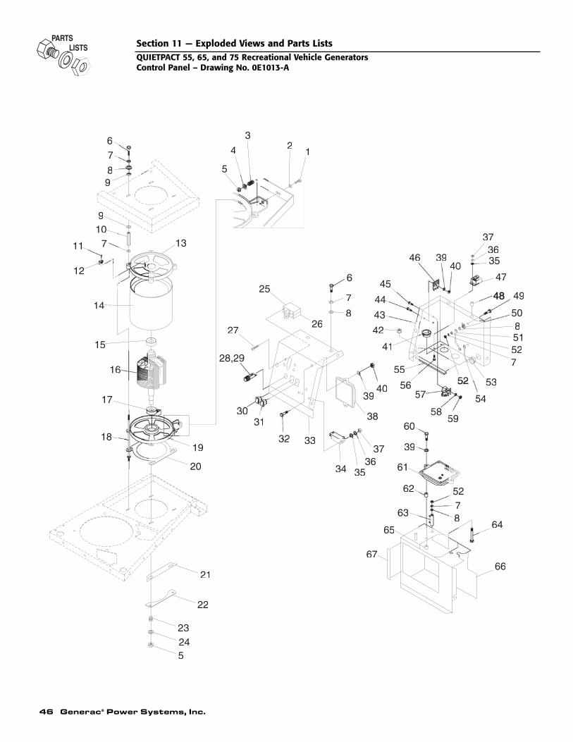
46 Generac® Power Systems, Inc.
12
3
4
5
67
89
910
11
122
13
144
15
16
17
1819
20
21
22
23245
25
26277
28,2
3031
32 33
34 3536
37
3940
41
42
43
444
455
46 3940
373635
47
49
50851527
53
54
55
565
5960
39
61
62
63 87
6465
66
8
7
67
Section 11 — Exploded Views and Parts ListsQUIETPACT 55, 65, and 75 Recreational Vehicle GeneratorsControl Panel – Drawing No. 0E1013-A
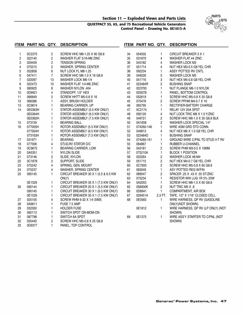
Generac® Power Systems, Inc. 47
ITEM PART NO. QTY. DESCRIPTION
1 0C2375 2 SCREW HHC M8-1.25 X 90 G8.82 022145 2 WASHER FLAT 5/16-M8 ZINC3 029459 2 TENSION SPRING4 075215 2 WASHER, SPRING CENTER5 052858 6 NUT LOCK FL M8-1.256 047411 7 SCREW HHC M6-1.0 X 16 G8.87 022097 13 WASHER LOCK M6-1/48 022473 10 WASHER FLAT 1/4-M6 ZINC9 080925 8 WASHER NYLON .404
10 0D9921 4 STANDOFF, 1/2" HEX11 066849 2 SCREW HHTT M5-0.8 X 1612 066386 1 ASSY, BRUSH HOLDER13 0C9674 1 BEARING CARRIER, UP14 0E0363H 1 STATOR ASSEMBLY (5.5 KW ONLY)
0E0364H 1 STATOR ASSEMBLY (6.5 KW ONLY)0E0362H 1 STATOR ASSEMBLY (7.5 KW ONLY)
15 073159 1 BEARING BALL16 077005H 1 ROTOR ASSEMBLY (5.5 KW ONLY)
077004H 1 ROTOR ASSEMBLY (6.5 KW ONLY)073163H 1 ROTOR ASSEMBLY (7.5 KW ONLY)
17 031971 1 BEARING18 077006 4 STUD,RV STATOR D/C19 0C9675 1 BEARING CARRIER, LOW20 0A5351 1 NYLON SLIDE 21 073146 2 SLIDE, NYLON22 0C1878 2 SUPPORT, SLIDE23 075242 4 SPRING, GEN. MOUNT24 075237 4 WASHER, SPRING CENTER25 090145 1 CIRCUIT BREAKER 30 X 1 (5.5 & 6.5 KW
ONLY)0E1529 1 CIRCUIT BREAKER 35 X 1 (7.5 KW ONLY)
26 090144 1 CIRCUIT BREAKER 20 X 1 (5.5 KW ONLY)090145 1 CIRCUIT BREAKER 30 X 1 (6.5 KW ONLY)0E1529 1 CIRCUIT BREAKER 35 X 1 (7.5 KW ONLY)
27 025105 4 SCREW RHM 6-32 X 1/4 SIMS28 0A9611 1 FUSE 7.5 AMP29 032300 1 HOLDER FUSE30 092113 1 SWITCH SPDT ON-MOM-ON31 087798 1 SWITCH 6A SPDT32 055440 2 SCREW HHC M5-0.8 X 25 G8.833 0D9377 1 PANEL, TOP CONTROL
ITEM PART NO. QTY. DESCRIPTION
34 054502 1 CIRCUIT BREAKER 3 X 135 031879 4 WASHER FLAT #4 ZINC36 043182 4 WASHER LOCK M337 051714 4 NUT HEX M3-0.5 G8 YEL CHR38 092234 1 ASSY POTTED RV CNTL39 049226 5 WASHER LOCK M540 051716 3 NUT HEX M5-0.8 G8 YEL CHR41 023484R 2 BUSHING SNAP42 0D3700 1 NUT FLANGE M6-1.0 NYLOK43 0D9378 1 PANEL, BOTTOM CONTROL44 052619 1 SCREW HHC M5-0.8 X 20 G8.845 075476 2 SCREW PPHM M4-0.7 X 1646 065795 1 RECTIFIER-BATTERY CHARGE47 0C2174 1 RELAY 12V 25A SPST48 092120 4 NUT LOCK TRIC M6 X 1.0 Y/ZNC49 049721 2 SCREW HHC M6-1.0 X 35 G8.8 BLK50 0A1658 2 WASHER LOCK SPECIAL 1/4"51 074260-146 1 WIRE ASM GRD STD CONN.52 049813 4 NUT HEX M6 X 1.0 G8 YEL CHR53 023484D 1 BUSHING SNAP54 074260-151 1 GROUND WIRE C/PNL TO STUD V-T RV55 084867 1 RUBBER U-CHANNEL56 043181 2 SCREW PHM M3-0.5 X 10MM57 075210A 1 BLOCK 1 POSITION58 022264 2 WASHER LOCK #8-M459 051715 2 NUT HEX M4-0.7 G8 YEL CHR60 0C7605 2 SCREW HHC M5-0.8 X 60 G8.861 083049 1 ASY POTTED REG W/FIN62 089047 2 SPACER .25 X .43 X .55 ST/ZNC63 075234 1 RESISTOR WW LUG 1R 5% 25W64 0A2053 1 SCREW HHC M6-1.0 X 65 G8.865 058000K 2 NUT TRIC M5 X .866 0D8941 1 COMPARTMENT, AIR BOX67 029451A 2.3 FT. TAPE, 1/2" X 1/16" CLOSED CELL68 0E0583 1 WIRE HARNESS, QP RV (GASOLINE
ONLY)(NOT SHOWN)0E1812 1 WIRE HARNESS, QP RV (LP ONLY) (NOT
SHOWN)69 0E1375 1 WIRE ASS'Y STARTER TO C/PNL (NOT
SHOWN)
Section 11 — Exploded Views and Parts ListsQUIETPACT 55, 65, and 75 Recreational Vehicle Generators
Control Panel – Drawing No. 0E1013-A
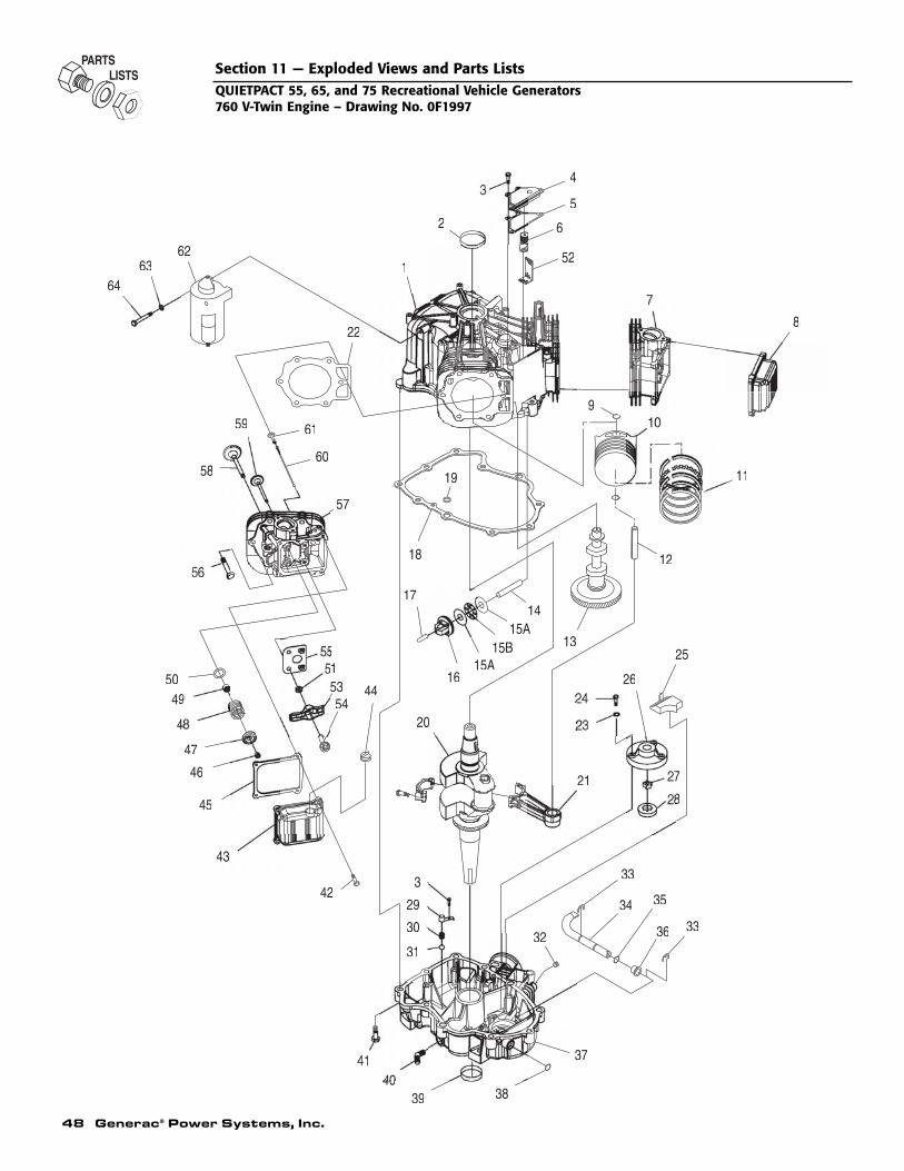
48 Generac® Power Systems, Inc.
Section 11 — Exploded Views and Parts ListsQUIETPACT 55, 65, and 75 Recreational Vehicle Generators760 V-Twin Engine – Drawing No. 0F1997
16364
333
29
31
30
40
42
39 38
32
37
34 35
36 33
18
17
4
47
46
45
43
5049
51
5453
5
44
59
58
61
57
60
22
20
15A16
15B15A
14
2
218
7
26
13
2
25
19
12
9
62
625
52
4
11
8
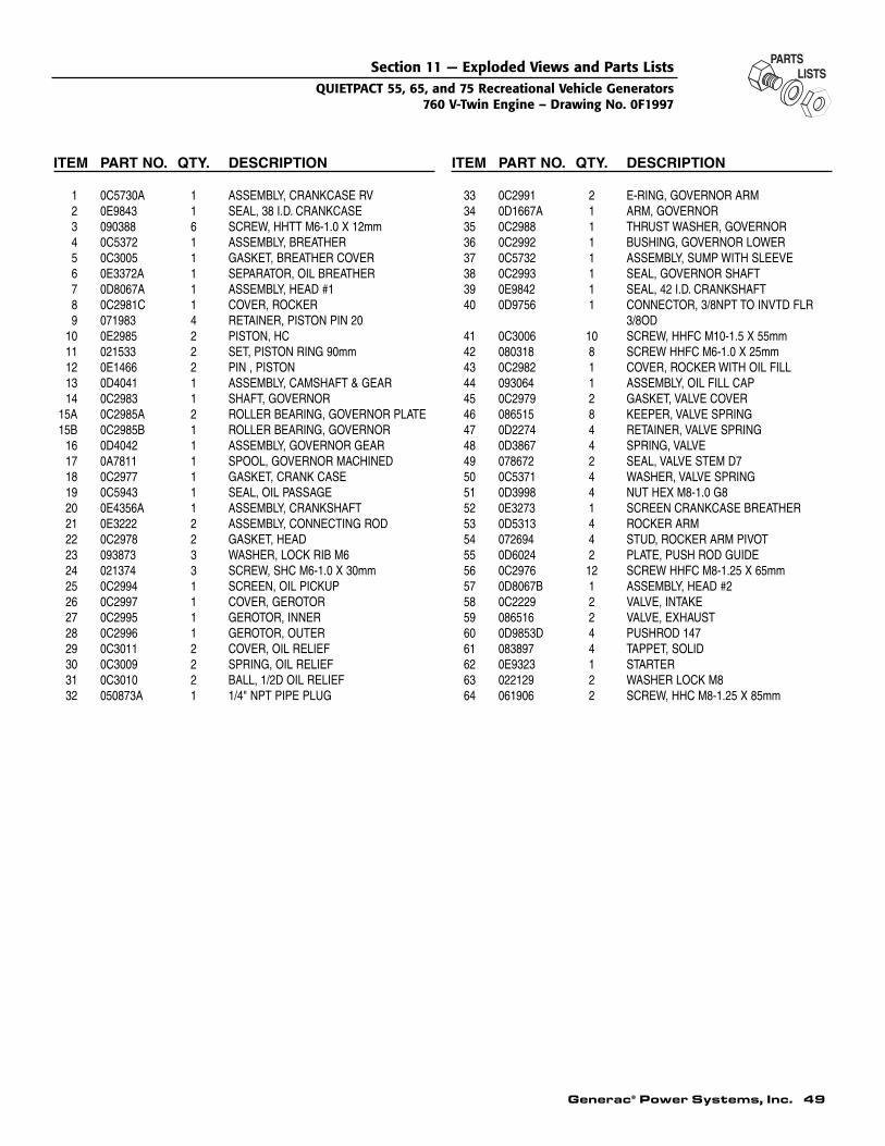
Generac® Power Systems, Inc. 49
ITEM PART NO. QTY. DESCRIPTION
1 0C5730A 1 ASSEMBLY, CRANKCASE RV2 0E9843 1 SEAL, 38 I.D. CRANKCASE 3 090388 6 SCREW, HHTT M6-1.0 X 12mm4 0C5372 1 ASSEMBLY, BREATHER5 0C3005 1 GASKET, BREATHER COVER6 0E3372A 1 SEPARATOR, OIL BREATHER7 0D8067A 1 ASSEMBLY, HEAD #18 0C2981C 1 COVER, ROCKER9 071983 4 RETAINER, PISTON PIN 20
10 0E2985 2 PISTON, HC11 021533 2 SET, PISTON RING 90mm12 0E1466 2 PIN , PISTON13 0D4041 1 ASSEMBLY, CAMSHAFT & GEAR14 0C2983 1 SHAFT, GOVERNOR
15A 0C2985A 2 ROLLER BEARING, GOVERNOR PLATE15B 0C2985B 1 ROLLER BEARING, GOVERNOR
16 0D4042 1 ASSEMBLY, GOVERNOR GEAR17 0A7811 1 SPOOL, GOVERNOR MACHINED18 0C2977 1 GASKET, CRANK CASE19 0C5943 1 SEAL, OIL PASSAGE20 0E4356A 1 ASSEMBLY, CRANKSHAFT21 0E3222 2 ASSEMBLY, CONNECTING ROD22 0C2978 2 GASKET, HEAD23 093873 3 WASHER, LOCK RIB M624 021374 3 SCREW, SHC M6-1.0 X 30mm25 0C2994 1 SCREEN, OIL PICKUP26 0C2997 1 COVER, GEROTOR27 0C2995 1 GEROTOR, INNER28 0C2996 1 GEROTOR, OUTER29 0C3011 2 COVER, OIL RELIEF30 0C3009 2 SPRING, OIL RELIEF31 0C3010 2 BALL, 1/2D OIL RELIEF32 050873A 1 1/4" NPT PIPE PLUG
ITEM PART NO. QTY. DESCRIPTION
33 0C2991 2 E-RING, GOVERNOR ARM34 0D1667A 1 ARM, GOVERNOR35 0C2988 1 THRUST WASHER, GOVERNOR36 0C2992 1 BUSHING, GOVERNOR LOWER37 0C5732 1 ASSEMBLY, SUMP WITH SLEEVE38 0C2993 1 SEAL, GOVERNOR SHAFT39 0E9842 1 SEAL, 42 I.D. CRANKSHAFT40 0D9756 1 CONNECTOR, 3/8NPT TO INVTD FLR
3/8OD41 0C3006 10 SCREW, HHFC M10-1.5 X 55mm42 080318 8 SCREW HHFC M6-1.0 X 25mm43 0C2982 1 COVER, ROCKER WITH OIL FILL44 093064 1 ASSEMBLY, OIL FILL CAP45 0C2979 2 GASKET, VALVE COVER46 086515 8 KEEPER, VALVE SPRING47 0D2274 4 RETAINER, VALVE SPRING48 0D3867 4 SPRING, VALVE49 078672 2 SEAL, VALVE STEM D750 0C5371 4 WASHER, VALVE SPRING51 0D3998 4 NUT HEX M8-1.0 G852 0E3273 1 SCREEN CRANKCASE BREATHER53 0D5313 4 ROCKER ARM54 072694 4 STUD, ROCKER ARM PIVOT55 0D6024 2 PLATE, PUSH ROD GUIDE56 0C2976 12 SCREW HHFC M8-1.25 X 65mm57 0D8067B 1 ASSEMBLY, HEAD #258 0C2229 2 VALVE, INTAKE59 086516 2 VALVE, EXHAUST60 0D9853D 4 PUSHROD 14761 083897 4 TAPPET, SOLID62 0E9323 1 STARTER63 022129 2 WASHER LOCK M864 061906 2 SCREW, HHC M8-1.25 X 85mm
Section 11 — Exploded Views and Parts ListsQUIETPACT 55, 65, and 75 Recreational Vehicle Generators
760 V-Twin Engine – Drawing No. 0F1997
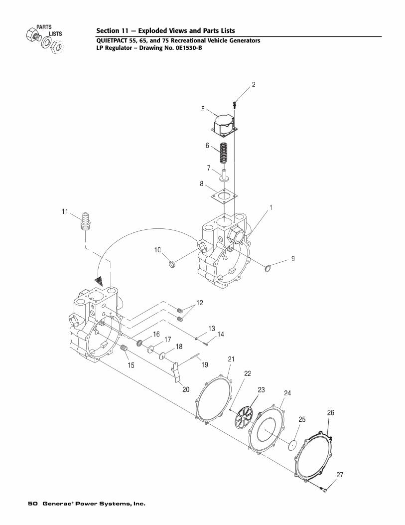
50 Generac® Power Systems, Inc.
11
16 1413
20
18
15
17
1921
25
23
22
24
27
26
10
12
6
8
7
5
1
9
2
Section 11 — Exploded Views and Parts ListsQUIETPACT 55, 65, and 75 Recreational Vehicle GeneratorsLP Regulator – Drawing No. 0E1530-B
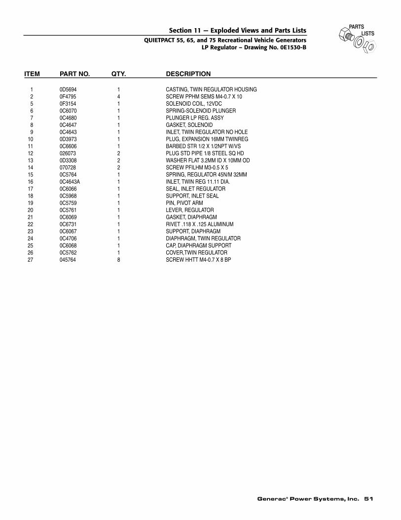
Generac® Power Systems, Inc. 51
ITEM PART NO. QTY. DESCRIPTION
1 0D5694 1 CASTING, TWIN REGULATOR HOUSING2 0F4795 4 SCREW PPHM SEMS M4-0.7 X 10⁵ 0F3154 1 SOLENOID COIL, 12VDC6 0C6070 1 SPRING-SOLENOID PLUNGER7 0C4680 1 PLUNGER LP REG. ASSY8 0C4647 1 GASKET, SOLENOID9 0C4643 1 INLET, TWIN REGULATOR NO HOLE
10 0D3973 1 PLUG, EXPANSION 16MM TWINREG11 0C6606 1 BARBED STR 1/2 X 1/2NPT W/VS12 026073 2 PLUG STD PIPE 1/8 STEEL SQ HD13 0D3308 2 WASHER FLAT 3.2MM ID X 10MM OD14 070728 2 SCREW PFILHM M3-0.5 X 515 0C5764 1 SPRING, REGULATOR 45N/M 32MM16 0C4643A 1 INLET, TWIN REG 11.11 DIA.17 0C6066 1 SEAL, INLET REGULATOR18 0C5968 1 SUPPORT, INLET SEAL19 0C5759 1 PIN, PIVOT ARM20 0C5761 1 LEVER, REGULATOR21 0C6069 1 GASKET, DIAPHRAGM22 0C6731 1 RIVET .118 X .125 ALUMINUM23 0C6067 1 SUPPORT, DIAPHRAGM24 0C4706 1 DIAPHRAGM, TWIN REGULATOR 25 0C6068 1 CAP, DIAPHRAGM SUPPORT26 0C5762 1 COVER,TWIN REGULATOR27 045764 8 SCREW HHTT M4-0.7 X 8 BP
Section 11 — Exploded Views and Parts ListsQUIETPACT 55, 65, and 75 Recreational Vehicle Generators
LP Regulator – Drawing No. 0E1530-B

52 Generac® Power Systems, Inc.
Section 12 – WarrantyQUIETPACT 55, 65, and 75 Recreational Vehicle Generators
CALIFORNIA AND FEDERAL EMISSION CONTROL WARRANTY STATEMENT
YOUR WARRANTY RIGHTS AND OBLIGATIONSThe California Air Resources Board (CARB) and the United States Environmental Protection Agency (EPA), together withGenerac Power Systems, Inc. (Generac), are pleased to explain the Emission Control System Warranty on your new engine.*New utility, and lawn and garden equipment engines must be designed, built and equipped to meet stringent anti-smog stan-dards for the state of California and the federal government. Generac will warrant the emission control system on yourengine for the periods of time listed below provided there has been no abuse, neglect, unapproved modification or improp-er maintenance of your engine.
Your emission control system may include parts such as the carburetor, ignition and exhaust systems. Generac will repairyour engine at no cost to you for diagnosis, replacement parts and labor, should a warrantable condition occur.
MANUFACTURER’S EMISSION CONTROL SYSTEM WARRANTY COVERAGE:Emissions control systems on 1997 and later model year engines are warranted for two years as hereinafter noted. If, dur-ing such warranty period, any emission-related component or system on your engine is found to be defective in materials orworkmanship, repairs or replacement will be performed by a Generac Authorized Warranty Service Facility.
PURCHASER’S/OWNER’S WARRANTY RESPONSIBILITIES:As the engine purchaser/owner, you are responsible for the completion of all required maintenance as listed in your factorysupplied Owner’s Manual. For warranty purposes, Generac recommends that you retain all receipts covering maintenanceon your engine. However, Generac cannot deny warranty solely because of the lack of receipts or for your failure to ensurethe completion of all scheduled maintenance.
As the engine purchaser/owner, you should, however, be aware that Generac may deny any and/or all warranty coverage orresponsibility if your engine, or a part/component thereof, has failed due to abuse, neglect, improper maintenance or unap-proved modifications, or the use of counterfeit and/or ‘grey market’ parts not made, supplied or approved by Generac.
You are responsible for presenting your engine to a Generac Authorized Warranty Service Facility as soon as a prob-lem occurs. The warranty repairs should be completed in a reasonable amount of time, not to exceed 30 days.
Warranty service can be arranged by contacting either your selling dealer or a Generac Authorized Warranty Service Facility.To locate the Generac Authorized Warranty Service Facility nearest you, call our toll-free number:
1-800-333-1322IMPORTANT NOTE: This warranty statement explains your rights and obligations under the Emission Control SystemWarranty (ECS Warranty), which is provided to you by Generac pursuant to California and federal law. See also the “GeneracLimited Warranties for Generac Power Systems, Inc.,” which is enclosed herewith on a separate sheet, also provided to youby Generac. The ECS Warranty applies only to the emission control system of your new engine. If there is any conflict interms between the ECS Warranty and the Generac Warranty, the ECS Warranty shall apply except in circumstances wherethe Generac Warranty may provide a longer warranty period. Both the ECS Warranty and the Generac Warranty describeimportant rights and obligations with respect to your new engine.
Warranty service can be performed only by a Generac Authorized Warranty Service Facility. When requesting warranty ser-vice, evidence must be presented showing the date of the sale to the original purchaser/owner. The purchaser/owner shallbe responsible for any expenses or other charges incurred for service calls and/or transportation of the product to/from theinspection or repair facilities. The purchaser/owner also shall be responsible for any and/or all damages or losses incurredwhile the engine is being transported/shipped for inspection or warranty repairs.
If you have any questions regarding your warranty rights and responsibilities, you should contact Generac at the fol-lowing address:
ATTENTION WARRANTY DEPARTMENTGENERAC POWER SYSTEMS, INC.
P.O. BOX 297WHITEWATER, WI 53190
Part 1

Generac® Power Systems, Inc. 53
Section 12 – WarrantyQUIETPACT 55, 65, and 75 Recreational Vehicle Generators
EMISSION CONTROL SYSTEM WARRANTYEmission Control System Warranty (ECS Warranty) for 1997 and later model year engines:
(a) Applicability: This warranty shall apply to 1997 and later model year engines. The ECS Warranty Period shall begin onthe date the new engine or equipment is purchased by/delivered to its original, end-use purchaser/owner and shall contin-ue for 24 consecutive months thereafter.
(b) General Emissions Warranty Coverage: Generac warrants to the original, end-use purchaser/owner of the new engine orequipment, and to each subsequent purchaser/owner, that each of its engines is ...(1) Designed, built and equipped so as to conform with all applicable regulations adopted by the EPA and CARB pursuant
to their respective authority, and(2) Free from defects in materials and workmanship which, at any time during the ECS Warranty Period, may cause a war-
ranted emissions-related part to fail to be identical in all material respects to the part as described in the engine manu-facturer’s application for certification.
(c) The ECS Warranty only pertains to emissions-related parts on your engine, as follows:(1) Any warranted, emissions-related parts that are not scheduled for replacement as required maintenance in the Owner’s
Manual shall be warranted for the ECS Warranty Period. If any such part fails during the ECS Warranty Period, it shallbe repaired or replaced by Generac according to Subsection (4) below. Any such part repaired or replaced under the ECSWarranty shall be warranted for the remainder of the ECS Warranty Period.
(2) Any warranted, emissions-related part that is scheduled only for regular inspection as specified in the Owner’s Manualshall be warranted for the ECS Warranty Period. A statement in such written instructions to the effect of “repair or replaceas necessary” shall not reduce the ECS Warranty Period. Any such part repaired or replaced under the ECS Warrantyshall be warranted for the remainder of the ECS Warranty Period.
(3) Any warranted, emissions-related part that is scheduled for replacement as required maintenance in the Owner’sManual shall be warranted for the period of time prior to the first scheduled replacement point for that part. If the partfails prior to the first scheduled replacement, the part shall be repaired or replaced by Generac according to Subsection(4) below. Any such emissions-related part repaired or replaced under the ECS Warranty shall be warranted for theremainder of the ECS Warranty Period prior to the first scheduled replacement point for such emissions-related part.
(4) Repair or replacement of any warranted, emissions-related part under this ECS Warranty shall be performed at nocharge to the owner at a Generac Authorized Warranty Service Facility.
(5) When the engine is inspected by a Generac Authorized Warranty Service Facility, the owner shall not be held responsi-ble for diagnostic costs if the repair is deemed warrantable.
(6) Generac shall be liable for damages to other original engine components or approved modifications proximately causedby a failure under warranty of any emission-related part covered by the ECS Warranty.
(7) Throughout the ECS Warranty Period, Generac shall maintain a supply of warranted emission-related parts sufficientto meet the expected demand for such emission-related parts.
(8) Any Generac authorized and approved emission-related replacement part may be used in the performance of any ECSWarranty maintenance or repairs and will be provided without charge to the purchaser/owner. Such use shall not reduceGenerac’s ECS Warranty obligations.
(9) Unapproved, add-on, modified, counterfeit and/or ‘grey market’ parts may not be used to modify or repair a Generacengine. Such use voids this ECS Warranty and shall be sufficient grounds for disallowing an ECS Warranty claim.Generac shall not be held liable hereunder for failures of any warranted parts of a Generac engine caused by the use ofsuch an unapproved, add-on, modified, counterfeit and/or ‘grey market’ part.
EMISSION RELATED PARTS INCLUDE THE FOLLOWING:
*Generac engine types covered by this warranty statement include the following:1) Utility2) Lawn and Garden Equipment3) Recreational Vehicle (RV) Generator4) Industrial Mobile (IM) Generator
Part 2
1) Fuel Metering System:1.1) Gasoline carburetor assembly and its
internal components (if so equipped).a) Fuel filter (if so equipped)b) Carburetor gasketsc) Fuel pump (if so equipped)1.2) LPG carburetion assembly and its
internal components (if so equipped).a) Fuel controller (if so equipped)b) Mixer and its gaskets (if so equipped)c) Carburetor and its gaskets (if so equipped)d) Primary gas regulator (if so equipped)e) LP liquid vaporizer (if so equipped)
2) Air Induction System including:a) Intake pipe/manifoldb) Air cleaner3) Ignition System including:a) Spark plugb) Ignition module4) Catalytic Muffler Assembly (if so equipped) including:a) Muffler gasketb) Exhaust manifold5) Crankcase Breather Assembly including: a) Breather connection tube

Part No. 0E1015 Revision J (12/20/04) Printed in U.S.A.
Section 12 – WarrantyQUIETPACT 55, 65, and 75 Recreational Vehicle Generators
GENERAC POWER SYSTEMS’ THREE-YEAR LIMITED WARRANTYFOR GUARDIAN RECREATIONAL VEHICLE GENERATORS
NOTE: ALL UNITS MUST BE INSTALLED BY GENERAC POWER SYSTEMS AUTHORIZED SERVICE FACILITIES.For a period of 3 (three) years of operation from the date of original sale, Generac Power Systems, Inc. (Generac) will, at itsoption, repair or replace any part which, upon examination, inspection and testing by Generac or a Generac AuthorizedWarranty Service Facility, is found to be defective under normal use and service, in accordance with the warranty scheduleset forth below. Any equipment that the purchaser/owner claims to be defective must be returned to and examined by thenearest Generac Authorized Warranty Service Facility. All transportation costs under the warranty, including return to thefactory, are to be borne and prepaid by the purchaser/owner. This warranty applies only to Generac generators sold andrated for “Recreational Vehicle” (RV) applications, as Generac has defined Recreational Vehicle generator applications. Thefactory recommends exercising the unit one half-hour every season.
WARRANTY SCHEDULE – COMMERCIAL APPLICATIONSYEAR ONE – 100% (one hundred percent) coverage on part(s), labor, removal and reinstallation listed:
• Engine – All components• Alternator – All components
WARRANTY SCHEDULE – CONSUMER/PERSONAL APPLICATIONSYEARS ONE AND TWO – 100% (one hundred percent) coverage on part(s), labor, removal and reinstallation listed:
• Engine – All components• Alternator – All componentsYEAR THREE – 100% (one hundred percent) only on selected part(s) and labor listed (Any labor and part(s) not listed, and
removal and reinstallation are the owner’s responsibility):• Rotor, Stator, Computer Control Board (part numbers 0A6060 and 0A3369) and inverter, (if applicable with regard to the gen-
erator) Cylinder Block, Cylinder Head, Crankshaft, Piston(s), Valve, Valve Lifter(s), Intake and Exhaust ManifoldsGenerac RV generators manufactured prior to December 31, 1997, DO NOT have a transferable warranty. Generac RV gen-erators manufactured after January 1, 1998, have a transferable warranty to the second owner ONLY for the remainder ofthe three-year limited warranty. Proof-of-purchase is required and must be presented to a Generac Authorized WarrantyService Facility prior to the performance of any warranty service.All warranty expense allowances are subject to the conditions defined in Guardian’s Warranty Policies and Procedures Guide.THIS WARRANTY SHALL NOT APPLY TO THE FOLLOWING:
• Generac Guardian generators that utilize non-Generac replacement parts.• Costs of normal maintenance, adjustments, installation and start-up.• Failures caused by any contaminated fuels, oils, coolants or lack of proper fluid amounts.• Failures due, but not limited, to normal wear and tear, accident, misuse, abuse, negligence or improper installation. As with
all mechanical devices, the Generac engines need periodic part(s) service and replacement to perform well. This warrantywill not cover repair when normal use has exhausted the life of a part(s) or engine.
• Failures caused by any external cause or act of God, such as collision, theft, vandalism, riot or wars, nuclear holocaust, fire,freezing, lightning, earthquake, windstorm, hail, volcanic eruption, water or flood, tornado or hurricane.
• Damage related to rodent and/or insect infestation.• Products that are modified or altered in a manner not authorized by Generac in writing.• Any incidental, consequential or indirect damages caused by defects in materials or workmanship, or any delay in repair or
replacement of the defective part(s).• Failure due to misapplication.• Telephone, cellular phone, facsimile, internet access or other communication expenses.• Living or travel expenses of person(s) performing service, except as specifically included within the terms of a specific unit
warranty period.• Expenses related to "customer instruction" or troubleshooting where no manufacturing defect is found.• Rental equipment used while warranty repairs are being performed.• Overnight freight costs for replacement part(s).• Overtime labor.• Starting batteries, fuses, light bulbs and engine fluids.
THIS WARRANTY IS IN PLACE OF ALL OTHER WARRANTIES, EXPRESSED OR IMPLIED. SPECIFICALLY, GENERAC MAKESNO OTHER WARRANTIES AS TO THE MERCHANTABILITY OR FITNESS FOR A PARTICULAR PURPOSE. Some states do notallow limitations on how long an implied warranty lasts, so the above limitation may not apply to you.GENERAC'S ONLY LIABILITY SHALL BE THE REPAIR OR REPLACEMENT OF PART(S) AS STATED ABOVE. IN NO EVENTSHALL GENERAC BE LIABLE FOR ANY INCIDENTAL OR CONSEQUENTIAL DAMAGES, EVEN IF SUCH DAMAGES ARE ADIRECT RESULT OF GENERAC'S NEGLIGENCE. Some states do not allow the exclusion or limitation of incidental or conse-quential damages, so the above limitation may not apply to you.This warranty gives you specific legal rights. You also have other rights from state to state.
GENERAC® POWER SYSTEMS, INC.P.O. BOX 297 • WHITEWATER, WI 53190
Revision 2.04


![[XLS] 7-10... · Web view1 0 0 0 2 0 0 0 3 0 0 0 4 0 0 0 5 0 0 0 6 0 0 0 7 0 0 0 8 0 0 0 9 0 0 0 10 0 0 0 11 0 0 0 12 0 0 0 13 0 0 0 14 0 0 0 15 0 0 0 16 0 0 0 17 0 0 0 18 0 0 0 19](https://img.pdfslide.us/doc/110x75/5ae8a6607f8b9a29049069b5/xls-7-10web-view1-0-0-0-2-0-0-0-3-0-0-0-4-0-0-0-5-0-0-0-6-0-0-0-7-0-0-0-8-0.jpg)


![[XLS] · Web view1101 0 0 0 0 11 0 0 12 0 0 13 0 0 14 0 0 15 0 0 16 0 0 17 0 0 18 0 0 19 0 0 51 1 1 0 0 81 2 0 0 3 0 0 0 0 0 0 0 0 0 0 0 0 0 0 0 0 0 1 1 0 0 2 0 0 3 0 0 0 0 0 0 0](https://img.pdfslide.us/doc/110x75/5ae8b1767f8b9a8b2b905346/xls-view1101-0-0-0-0-11-0-0-12-0-0-13-0-0-14-0-0-15-0-0-16-0-0-17-0-0-18-0-0-19.jpg)

![[XLS]mams.rmit.edu.aumams.rmit.edu.au/urs1erc4d2nv1.xlsx · Web view0. 0. 0. 0. 0. 0. 0. 0. 0. 0. 0. 0. 0. 0. 0. 0. 0. 0. 0. 0. 0. 0. 0. 0. 0. 0. 0. 0. 0. 0. 0. 0. 0. 0. 0. 0. 0](https://img.pdfslide.us/doc/110x75/5ab434027f8b9a0f058b8cff/xlsmamsrmitedu-view0-0-0-0-0-0-0-0-0-0-0-0-0-0-0-0-0-0-0.jpg)


![[XLS] · Web view0 0 7/31/2018 10/16/2017 0 0 39 40 41 42 43 0 2 0 0 0 0 2 0 0 0 0 2 0 0 0 0 1 0 0 0 0 2 0 0 0 0 1 0 0 0 0 2 0 0 0 0 2 0 0 0 0 2 0 0 0 0 2 0 0 0 0 2 0 0 0 0 2 0 0](https://img.pdfslide.us/doc/110x75/5afad2057f8b9a32348e4124/xls-view0-0-7312018-10162017-0-0-39-40-41-42-43-0-2-0-0-0-0-2-0-0-0-0-2-0.jpg)