Embed Size (px)
Citation preview
OWNER’SMANUAL
ASSEMBLY INSTALLATION OPERATION REPAIR PARTS
MODEL NUMBERSBJ90 AND SJ125
CAUTION:Read Rules and InstructionsCarefully for Safe Operation
IMPORTANT:Installation must be made inaccordance with State andLocal Ordinances which maydiffer from this InstallationManual.
SUPER JACKMODEL SJ125
BIG JACKMODEL BJ90
SUPER JACK & BIG JACKWOOD BURNING FURNACES
TESTED BYWARNOCK- HERSEY INTERNATIONAL
TO UL 391 STANDARDS
ALPHA AMERICAN CO., 10 INDUSTRIAL BLVD., PALISADE, MN 56469www.yukon-eagle.com
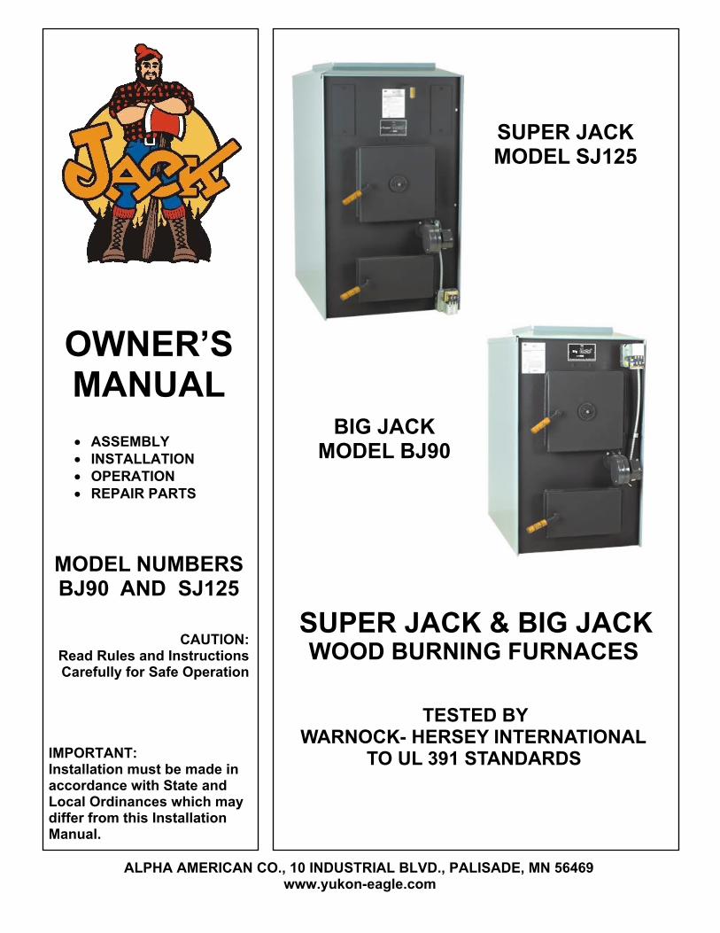
DANGERRISK OF FIRE OR EXPLOSION
Do not burn garbage, gasoline, drain oil, kerosene, thinners, etc.
WARNINGRISK OF FIRE
Tightly close the firing door and ash door during operation.
Do not operate with flue draft exceeding .03" W.C.
Do not store flammable materials within marked installation clearance.
Frequently inspect and clean soot and/or creosote from the heat exchanger,smoke pipe, and chimney.
Do not connect this unit to a chimney flue serving another appliance.
CAUTIONBLACK SURFACES ARE HOT
Keep children away. Do not touch.
Questions?Visit www.yukon-eagle.com
or call1-800-358-0060
For repair or replacement parts,See back cover for details.
Before installing thisfurnace, read and follow allinstructions in this manual.It is recommended that aheating professional installsor supervises the entireinstallation of the furnace,ducts, chimney andelectrical connections.
FOR YOUR SAFETY:If you smell gas:1. Open windows2. Do not touch electrical switches3. Extinguish any open flame4. Immediately call your gas supplier
FOR YOUR SAFETY:
Do not store or use gasoline orother flammable vapors andliquids in the vicinity of this orany other appliance.
2
3
TABLE OF CONTENTS
INTRODUCTION Safety Statements............................................................................................................................2, 4 Unpacking and Inspection...................................................................................................................5 Features and Benefits of SJ125.......................................................................................................6, 7Features and Benefits of BJ90 ........................................................................................................8, 9BJ90 Specifications ...........................................................................................................................10SJ125 Specifications .........................................................................................................................11
PLAN YOUR INSTALLATIONPlan your Installation ........................................................................................................................12Locating the Furnace ........................................................................................................................13Clearances to Combustibles .............................................................................................................13Typical Installations ..........................................................................................................................14Proper Chimneys ..............................................................................................................................15Furnace Located in Confined Space .................................................................................................16Combustion Air (Make Up Air) ........................................................................................................17
INSTALLATIONPlace Furnace ...................................................................................................................................18Furnace Casing .................................................................................................................................18Combustion Blower ..........................................................................................................................19Junction Box ...................................................................................................................................19Fan and Limit Control ......................................................................................................................20Mounting Thermostat .......................................................................................................................21Electrical Wiring ..............................................................................................................................22Wiring Diagram ................................................................................................................................23Connecting Smoke Pipe ...................................................................................................................24Barometric Draft Regulator ........................................................................................................25-27
OPERATING FURNACEBest Wood to Burn ..........................................................................................................................28Helpful Hints ...................................................................................................................................29Wood Firing the Furnace ..................................................................................................................30Burning Coal ..............................................................................................................................31, 32Ash Removal .....................................................................................................................................33
MAINTENANCEFaulty Chimney and Draft Problems ..........................................................................................34, 35Cleaning Chimney, Smoke Pipe and Heat Exchanger .....................................................................36
EXPLODED VIEWS AND PARTS LISTSSuper Jack (SJ125) .....................................................................................................................38, 39Big Jack (BJ90) ..........................................................................................................................40, 41
SERVICE HINTS & TROUBLESHOOTING.......................................................................42, 43YOUR NOTES ...........................................................................................................................44-47
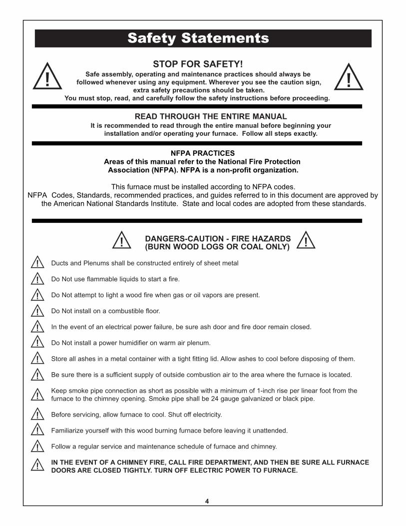
STOP FOR SAFETY!Safe assembly, operating and maintenance practices should always be
followed whenever using any equipment. Wherever you see the caution sign,extra safety precautions should be taken.
You must stop, read, and carefully follow the safety instructions before proceeding.
READ THROUGH THE ENTIRE MANUALIt is recommended to read through the entire manual before beginning your
installation and/or operating your furnace. Follow all steps exactly.
NFPA PRACTICESAreas of this manual refer to the National Fire Protection
Association (NFPA). NFPA is a non-profit organization.
This furnace must be installed according to NFPA codes.NFPA Codes, Standards, recommended practices, and guides referred to in this document are approved by
the American National Standards Institute. State and local codes are adopted from these standards.
DANGERS-CAUTION - FIRE HAZARDS(BURN WOOD LOGS OR COAL ONLY)
Ducts and Plenums shall be constructed entirely of sheet metal
Do Not use flammable liquids to start a fire.
Do Not attempt to light a wood fire when gas or oil vapors are present.
Do Not install on a combustible floor.
In the event of an electrical power failure, be sure ash door and fire door remain closed.
Do Not install a power humidifier on warm air plenum.
Store all ashes in a metal container with a tight fitting lid. Allow ashes to cool before disposing of them.
Be sure there is a sufficient supply of outside combustion air to the area where the furnace is located.
Keep smoke pipe connection as short as possible with a minimum of 1-inch rise per linear foot from thefurnace to the chimney opening. Smoke pipe shall be 24 gauge galvanized or black pipe.
Before servicing, allow furnace to cool. Shut off electricity.
Familiarize yourself with this wood burning furnace before leaving it unattended.
Follow a regular service and maintenance schedule of furnace and chimney.
IN THE EVENT OF A CHIMNEY FIRE, CALL FIRE DEPARTMENT, AND THEN BE SURE ALL FURNACEDOORS ARE CLOSED TIGHTLY. TURN OFF ELECTRIC POWER TO FURNACE.
Safety Statements
4
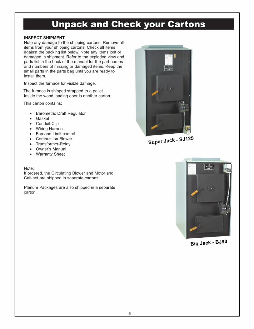
Unpack and Check your CartonsINSPECT SHIPMENTNote any damage to the shipping cartons. Remove allitems from your shipping cartons. Check all itemsagainst the packing list below. Note any items lost ordamaged in shipment. Refer to the exploded view andparts list in the back of the manual for the part namesand numbers of missing or damaged items. Keep thesmall parts in the parts bag until you are ready toinstall them.
Inspect the furnace for visible damage.
The furnace is shipped strapped to a pallet.Inside the wood loading door is another carton.
This carton contains:
· Barometric Draft Regulator· Gasket· Conduit Clip· Wiring Harness· Fan and Limit control· Combustion Blower· Transformer-Relay· Owner’s Manual· Warranty Sheet
Note:If ordered, the Circulating Blower and Motor andCabinet are shipped in separate cartons.
Plenum Packages are also shipped in a separatecarton.
Super Jack - SJ125
Big Jack - BJ90
5
Furnace Features - SJ125
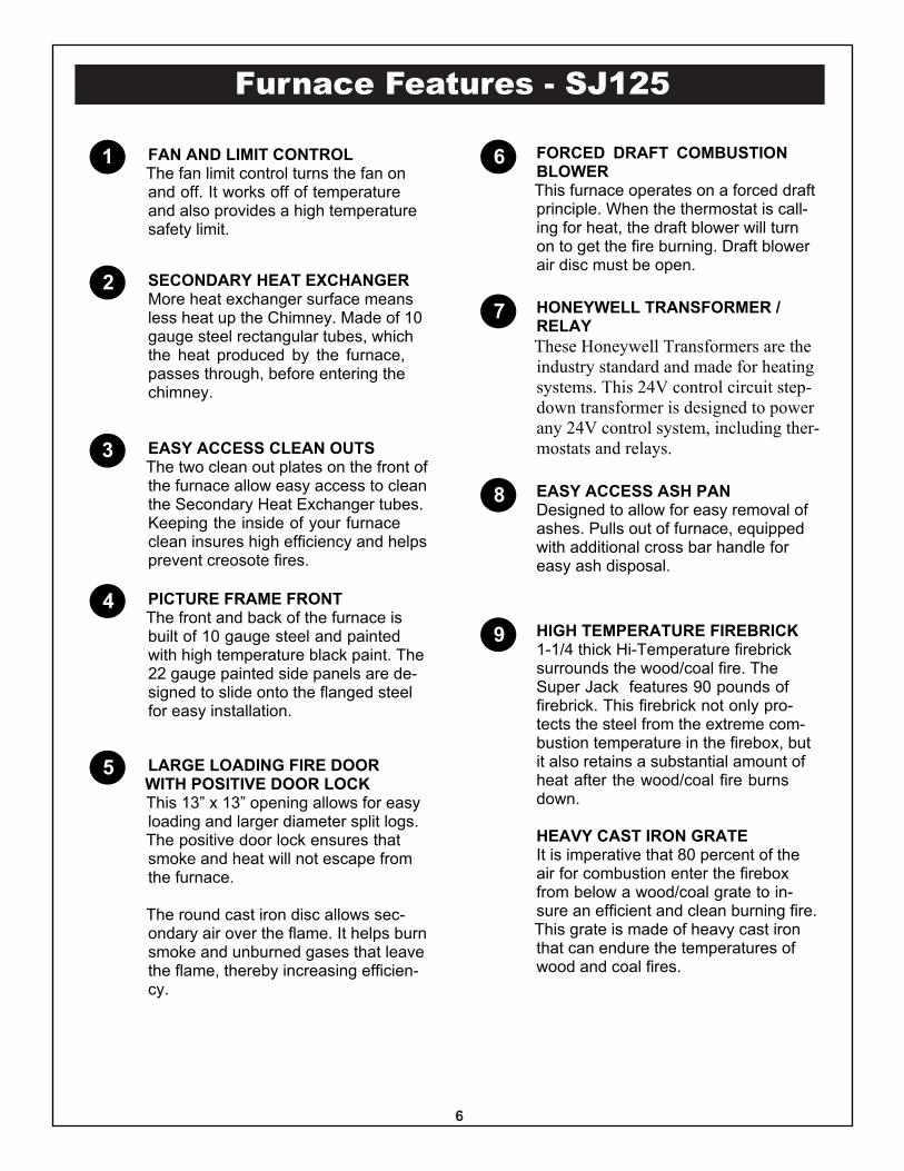
1 FAN AND LIMIT CONTROLThe fan limit control turns the fan onand off. It works off of temperatureand also provides a high temperaturesafety limit.
2
3
4
5
6
7
8
9
SECONDARY HEAT EXCHANGERMore heat exchanger surface meansless heat up the Chimney. Made of 10gauge steel rectangular tubes, whichthe heat produced by the furnace,passes through, before entering thechimney.
EASY ACCESS CLEAN OUTSThe two clean out plates on the front ofthe furnace allow easy access to cleanthe Secondary Heat Exchanger tubes.Keeping the inside of your furnaceclean insures high efficiency and helpsprevent creosote fires.
PICTURE FRAME FRONTThe front and back of the furnace isbuilt of 10 gauge steel and paintedwith high temperature black paint. The22 gauge painted side panels are de-signed to slide onto the flanged steelfor easy installation.
LARGE LOADING FIRE DOORWITH POSITIVE DOOR LOCKThis 13” x 13” opening allows for easyloading and larger diameter split logs.The positive door lock ensures thatsmoke and heat will not escape fromthe furnace.
The round cast iron disc allows sec-ondary air over the flame. It helps burnsmoke and unburned gases that leavethe flame, thereby increasing efficien-cy.
FORCED DRAFT COMBUSTIONBLOWERThis furnace operates on a forced draftprinciple. When the thermostat is call-ing for heat, the draft blower will turnon to get the fire burning. Draft blowerair disc must be open.
HONEYWELL TRANSFORMER /RELAYThese Honeywell Transformers are theindustry standard and made for heatingsystems. This 24V control circuit step-down transformer is designed to powerany 24V control system, including ther-mostats and relays.
EASY ACCESS ASH PANDesigned to allow for easy removal ofashes. Pulls out of furnace, equippedwith additional cross bar handle foreasy ash disposal.
HIGH TEMPERATURE FIREBRICK1-1/4 thick Hi-Temperature firebricksurrounds the wood/coal fire. TheSuper Jack features 90 pounds offirebrick. This firebrick not only pro-tects the steel from the extreme com-bustion temperature in the firebox, butit also retains a substantial amount ofheat after the wood/coal fire burnsdown.
HEAVY CAST IRON GRATEIt is imperative that 80 percent of theair for combustion enter the fireboxfrom below a wood/coal grate to in-sure an efficient and clean burning fire.This grate is made of heavy cast ironthat can endure the temperatures ofwood and coal fires.
6
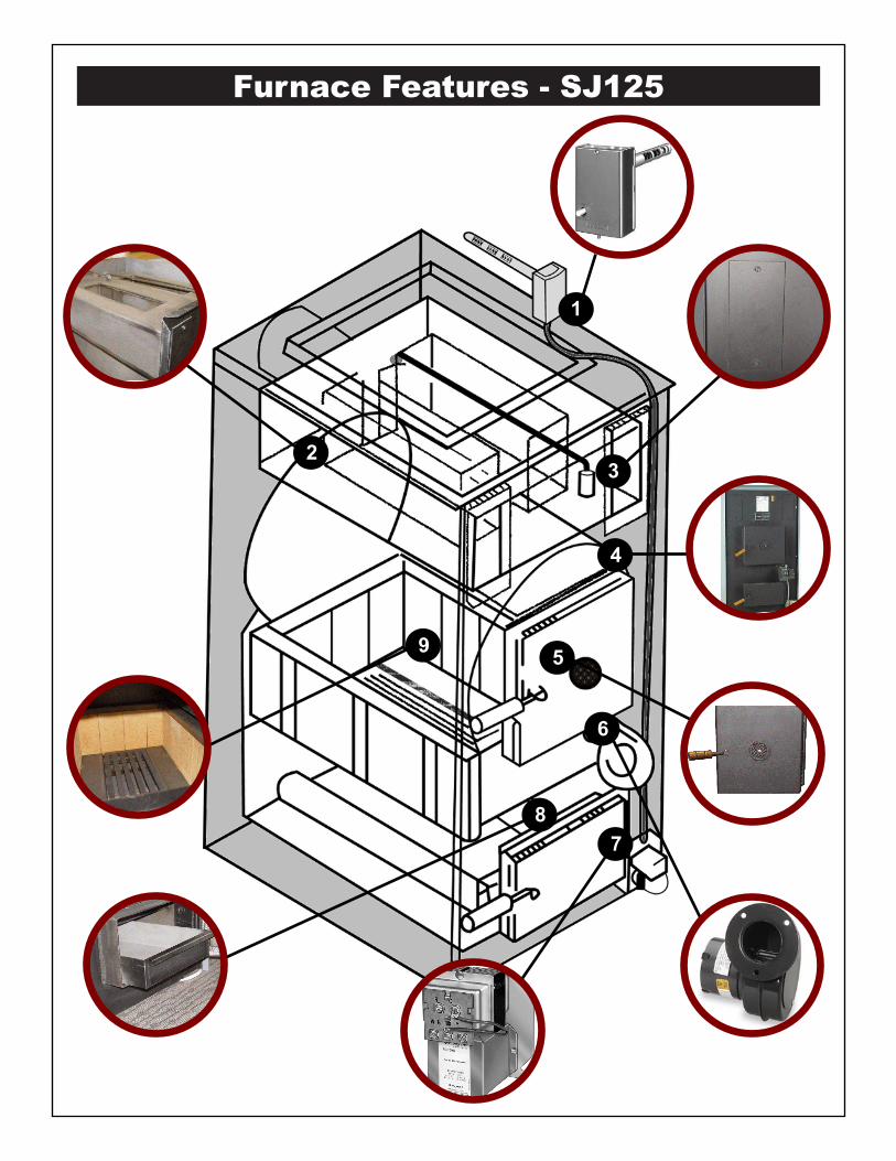
Furnace Features - SJ125
3
1
2
4
5
6
78
9
Furnace Features - BJ90
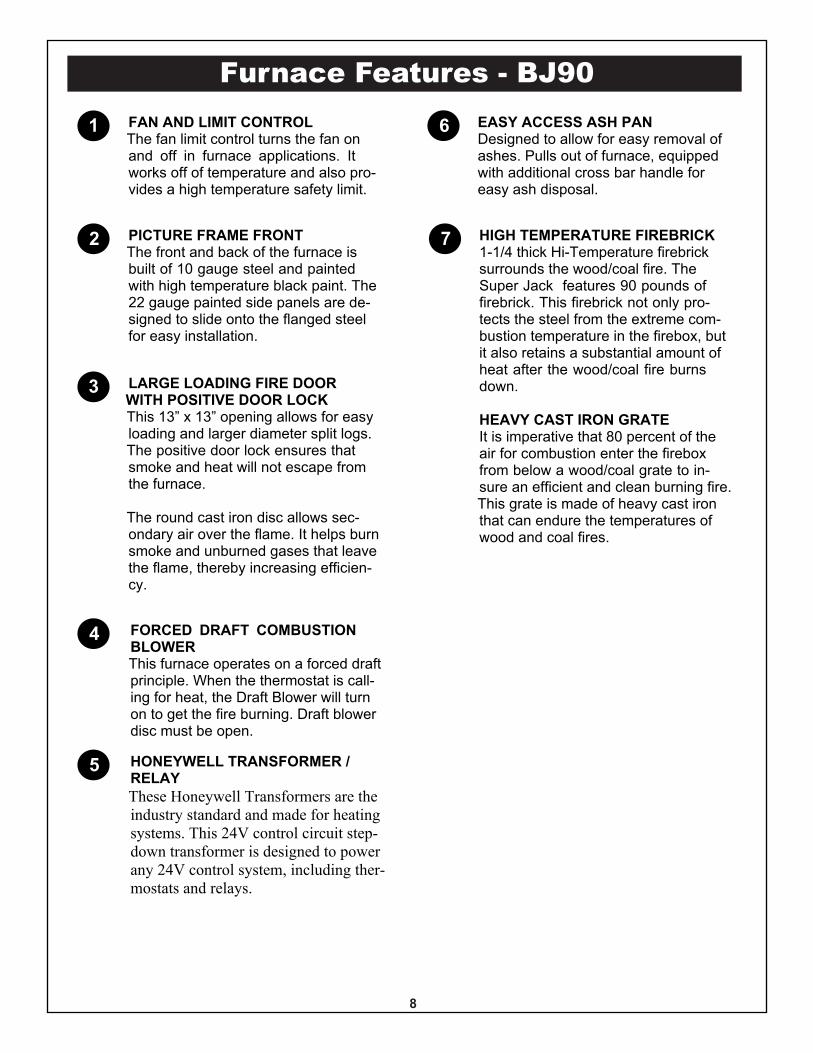
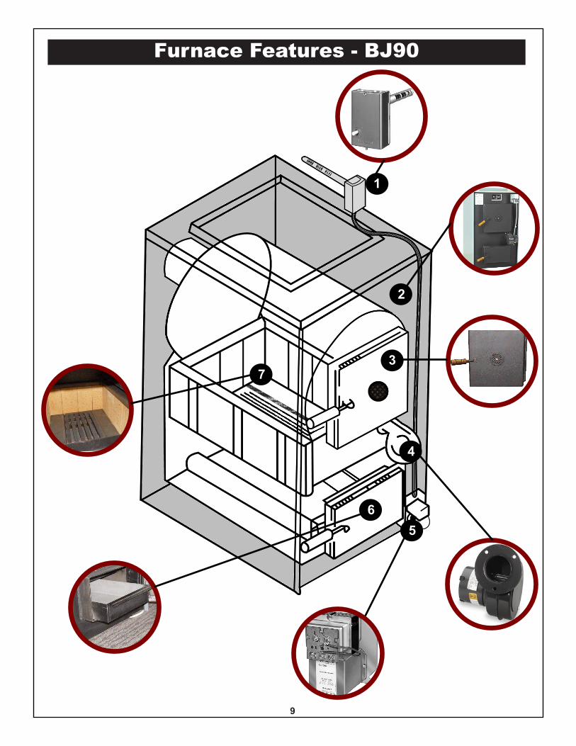
1 FAN AND LIMIT CONTROLThe fan limit control turns the fan onand off in furnace applications. Itworks off of temperature and also pro-vides a high temperature safety limit.
2
3
4
5
6
7PICTURE FRAME FRONTThe front and back of the furnace isbuilt of 10 gauge steel and paintedwith high temperature black paint. The22 gauge painted side panels are de-signed to slide onto the flanged steelfor easy installation.
LARGE LOADING FIRE DOORWITH POSITIVE DOOR LOCKThis 13” x 13” opening allows for easyloading and larger diameter split logs.The positive door lock ensures thatsmoke and heat will not escape fromthe furnace.
The round cast iron disc allows sec-ondary air over the flame. It helps burnsmoke and unburned gases that leavethe flame, thereby increasing efficien-cy.
FORCED DRAFT COMBUSTIONBLOWERThis furnace operates on a forced draftprinciple. When the thermostat is call-ing for heat, the Draft Blower will turnon to get the fire burning. Draft blowerdisc must be open.
HONEYWELL TRANSFORMER /RELAYThese Honeywell Transformers are theindustry standard and made for heatingsystems. This 24V control circuit step-down transformer is designed to powerany 24V control system, including ther-mostats and relays.
EASY ACCESS ASH PANDesigned to allow for easy removal ofashes. Pulls out of furnace, equippedwith additional cross bar handle foreasy ash disposal.
HIGH TEMPERATURE FIREBRICK1-1/4 thick Hi-Temperature firebricksurrounds the wood/coal fire. TheSuper Jack features 90 pounds offirebrick. This firebrick not only pro-tects the steel from the extreme com-bustion temperature in the firebox, butit also retains a substantial amount ofheat after the wood/coal fire burnsdown.
HEAVY CAST IRON GRATEIt is imperative that 80 percent of theair for combustion enter the fireboxfrom below a wood/coal grate to in-sure an efficient and clean burning fire.This grate is made of heavy cast ironthat can endure the temperatures ofwood and coal fires.
8
Furnace Features - BJ90
1
2
3
4
56
7
9
Specifications
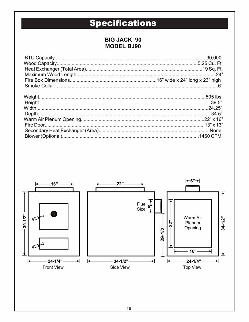
BIG JACK 90MODEL BJ90
BTU Capacity................................................................................................................90,000Wood Capacity........................................................................................................5.25 Cu. FtHeat Exchanger (Total Area)......................................................................................19 Sq. Ft.Maximum Wood Length.......................................................................................................24”Fire Box Dimensions................................................................16” wide x 24” long x 23” highSmoke Collar.........................................................................................................................6”
Weight...........................................................................................................................595 lbs.Height...............................................................................................................................39.5”Width...............................................................................................................................24.25”Depth................................................................................................................................34.5”Warm Air Plenum Opening...........................................................................................22” x 16”Fire Door......................................................................................................................13” x 13”Secondary Heat Exchanger (Area)..................................................................................NoneBlower (Optional).....................................................................................................1460 CFM
10
29-1
/2”
Specifications
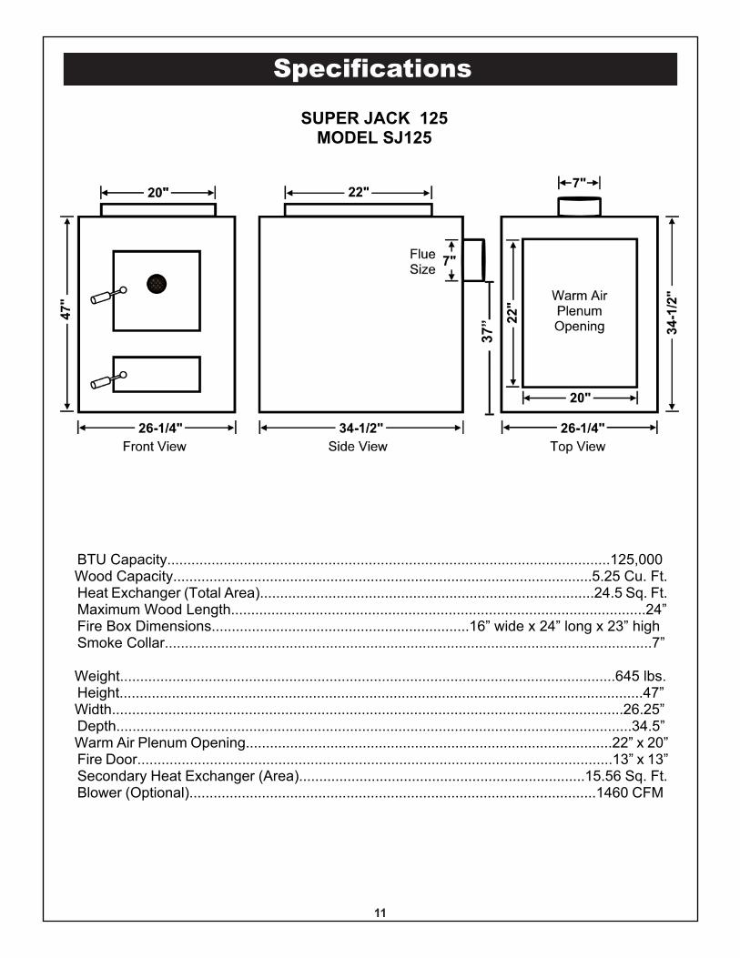
BTU Capacity..............................................................................................................125,000Wood Capacity........................................................................................................5.25 Cu. Ft.Heat Exchanger (Total Area)...................................................................................24.5 Sq. Ft.Maximum Wood Length.......................................................................................................24”Fire Box Dimensions................................................................16” wide x 24” long x 23” highSmoke Collar.........................................................................................................................7”
Weight...........................................................................................................................645 lbs.Height..................................................................................................................................47”Width...............................................................................................................................26.25”Depth................................................................................................................................34.5”Warm Air Plenum Opening...........................................................................................22” x 20”Fire Door......................................................................................................................13” x 13”Secondary Heat Exchanger (Area).......................................................................15.56 Sq. Ft.Blower (Optional).....................................................................................................1460 CFM
SUPER JACK 125MODEL SJ125
11
37”
Plan Your InstallationPLAN YOUR INSTALLATIONIt is recommended to read through the entire manualbefore beginning your installation. Follow all steps exactly.Reading this manual will also help you get all the benefitsfrom your furnace.
CAUTION: Read these rules and theinstructions carefully. Failure to follow theserules and instructions could cause amalfunction of the furnace. This couldresult in death, serious bodily injury and/orproperty damage.
IMPORTANT!
CHECKING THE FURNACE INSTALLATION ANDMAKING ADJUSTMENTSIt is imperative that a heating professional, before startupand at the beginning of each heating season, inspects theentire installation and make any necessary adjustments.
RULES FOR SAFE INSTALLATION AND OPERATION1. Check your local codes. The installation must comply
with them.
2. USE ONLY WOOD LOGS OR COAL in this furnace.Over firing will result in failure of heat exchanger andcause dangerous operation.
3. You must have a sufficient supply of outsidecombustion air to the area in which the furnace islocated. (See page 17).
4. Factory Built Chimneys: Connect this furnace to achimney that complies with NFPA 211. Factory builtchimneys for use with wood-burning appliances shallcomply with the HT requirements of UL 103 orCAN/ULC-S629-M87. This means you must install whatis referred to as type HT All Fuel chimney.
Masonry Chimneys: Connect this furnace to achimney that complies with NFPA 211. A fieldconstructed chimney of solid masonry units, bricks,stones, listed masonry chimney units, or reinforcedPortland cement concrete that is lined with suitablechimney flue liners and built in accordance with theprovisions of Chapter 4 of this standard.
5. Follow a regular service and maintenance schedule forefficient and safe operation.
6. Before servicing, allow furnace to cool. Always shut offelectricity to furnace.
12
DUCTS SHOULD BE LARGEENOUGH TO HANDLE GRAVITY AIRFLOW IN THE EVENT OF ELECTRICPOWER OR FURNACE FAN FAILURE
AIR CONDITIONING COIL MUST BEINSTALLED WITH A METAL
CONDENSATE PAN.
DO NOT USE PLASTICCONDENSATE PAN
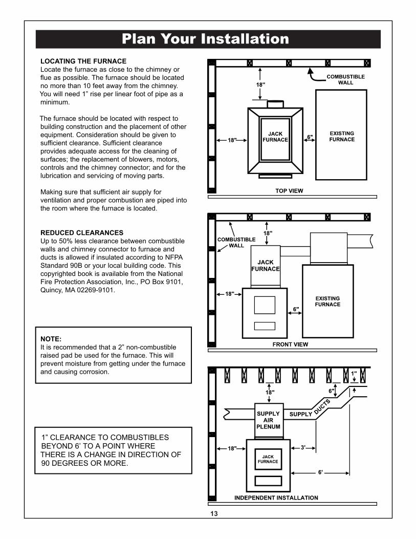
Plan Your InstallationLOCATING THE FURNACELocate the furnace as close to the chimney orflue as possible. The furnace should be locatedno more than 10 feet away from the chimney.You will need 1” rise per linear foot of pipe as aminimum.
The furnace should be located with respect tobuilding construction and the placement of otherequipment. Consideration should be given tosufficient clearance. Sufficient clearanceprovides adequate access for the cleaning ofsurfaces; the replacement of blowers, motors,controls and the chimney connector; and for thelubrication and servicing of moving parts.
Making sure that sufficient air supply forventilation and proper combustion are piped intothe room where the furnace is located.
REDUCED CLEARANCESUp to 50% less clearance between combustiblewalls and chimney connector to furnace andducts is allowed if insulated according to NFPAStandard 90B or your local building code. Thiscopyrighted book is available from the NationalFire Protection Association, Inc., PO Box 9101,Quincy, MA 02269-9101.
NOTE:It is recommended that a 2” non-combustibleraised pad be used for the furnace. This willprevent moisture from getting under the furnaceand causing corrosion.
13
1” CLEARANCE TO COMBUSTIBLESBEYOND 6’ TO A POINT WHERETHERE IS A CHANGE IN DIRECTION OF90 DEGREES OR MORE.
Plan Your Installation
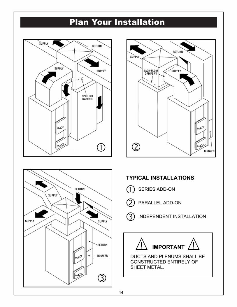
TYPICAL INSTALLATIONS
� SERIES ADD-ON
� PARALLEL ADD-ON
� INDEPENDENT INSTALLATION
� �
�
DUCTS AND PLENUMS SHALL BECONSTRUCTED ENTIRELY OFSHEET METAL.
IMPORTANT! !
14
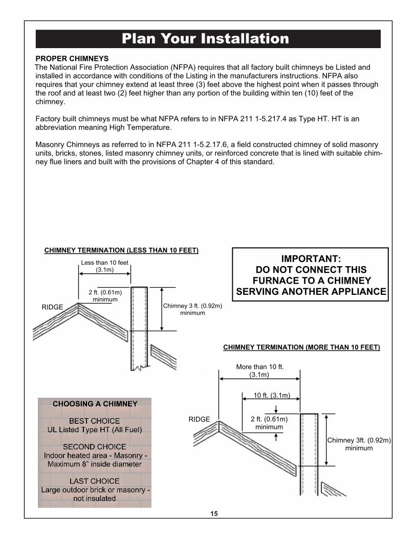
PROPER CHIMNEYSThe National Fire Protection Association (NFPA) requires that all factory built chimneys be Listed andinstalled in accordance with conditions of the Listing in the manufacturers instructions. NFPA alsorequires that your chimney extend at least three (3) feet above the highest point when it passes throughthe roof and at least two (2) feet higher than any portion of the building within ten (10) feet of thechimney.
Factory built chimneys must be what NFPA refers to in NFPA 211 1-5.217.4 as Type HT. HT is anabbreviation meaning High Temperature.
Masonry Chimneys as referred to in NFPA 211 1-5.2.17.6, a field constructed chimney of solid masonryunits, bricks, stones, listed masonry chimney units, or reinforced concrete that is lined with suitable chim-ney flue liners and built with the provisions of Chapter 4 of this standard.
RIDGE
More than 10 ft.(3.1m)
10 ft. (3.1m)
2 ft. (0.61m)minimum
Chimney 3ft. (0.92m)minimum
RIDGE
Less than 10 feet(3.1m)
2 ft. (0.61m)minimum
Chimney 3 ft. (0.92m)minimum
CHIMNEY TERMINATION (LESS THAN 10 FEET)
CHIMNEY TERMINATION (MORE THAN 10 FEET)
Plan Your Installation
IMPORTANT:DO NOT CONNECT THIS
FURNACE TO A CHIMNEYSERVING ANOTHER APPLIANCE
15
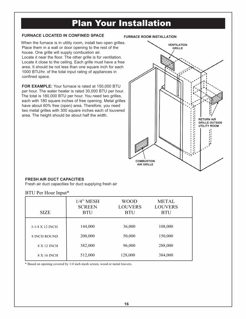
Plan Your InstallationFURNACE LOCATED IN CONFINED SPACE
When the furnace is in utility room, install two open grilles.Place them in a wall or door opening to the rest of thehouse. One grille will supply combustion air.Locate it near the floor. The other grille is for ventilation.Locate it close to the ceiling. Each grille must have a freearea. It should be not less than one square inch for each1000 BTU/hr. of the total input rating of appliances inconfined space.
FOR EXAMPLE: Your furnace is rated at 150,000 BTUper hour. The water heater is rated 30,000 BTU per hour.The total is 180,000 BTU per hour. You need two grilles,each with 180 square inches of free opening. Metal grilleshave about 60% free (open) area. Therefore, you needtwo metal grilles with 300 square inches each of louveredarea. The height should be about half the width.
SIZE
1/4” MESHSCREEN
BTU
WOODLOUVERS
BTU
METALLOUVERS
BTU
3-1/4 X 12 INCH
8 INCH ROUND
8 X 12 INCH
8 X 16 INCH
144,000
200,000
382,000
512,000
36,000
50,000
96,000
128,000
108,000
150,000
288,000
384,000
BTU Per Hour Input*
* Based on opening covered by 1/4 inch mesh screen, wood or metal louvers.
FRESH AIR DUCT CAPACITIESFresh air duct capacities for duct supplying fresh air
16
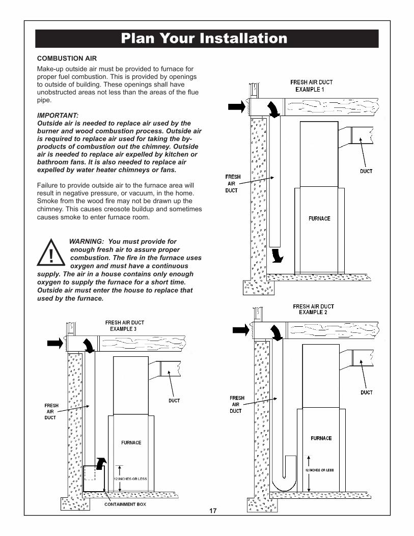
Plan Your InstallationCOMBUSTION AIRMake-up outside air must be provided to furnace forproper fuel combustion. This is provided by openingsto outside of building. These openings shall haveunobstructed areas not less than the areas of the fluepipe.
IMPORTANT:Outside air is needed to replace air used by theburner and wood combustion process. Outside airis required to replace air used for taking the by-products of combustion out the chimney. Outsideair is needed to replace air expelled by kitchen orbathroom fans. It is also needed to replace airexpelled by water heater chimneys or fans.
Failure to provide outside air to the furnace area willresult in negative pressure, or vacuum, in the home.Smoke from the wood fire may not be drawn up thechimney. This causes creosote buildup and sometimescauses smoke to enter furnace room.
WARNING: You must provide forenough fresh air to assure propercombustion. The fire in the furnace usesoxygen and must have a continuous
supply. The air in a house contains only enoughoxygen to supply the furnace for a short time.Outside air must enter the house to replace thatused by the furnace.
17
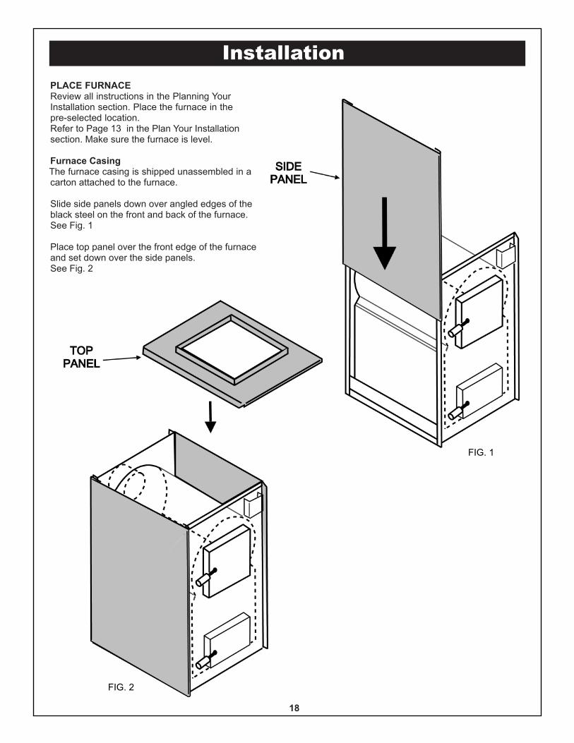
InstallationPLACE FURNACEReview all instructions in the Planning YourInstallation section. Place the furnace in thepre-selected location.Refer to Page 13 in the Plan Your Installationsection. Make sure the furnace is level.
Furnace CasingThe furnace casing is shipped unassembled in acarton attached to the furnace.
Slide side panels down over angled edges of theblack steel on the front and back of the furnace.See Fig. 1
Place top panel over the front edge of the furnaceand set down over the side panels.See Fig. 2
18
FIG. 1
FIG. 2
Installation
Big Jack
Super JackJunction BoxMounting Bracket
Junction BoxMounting Bracket
Combustion Blower
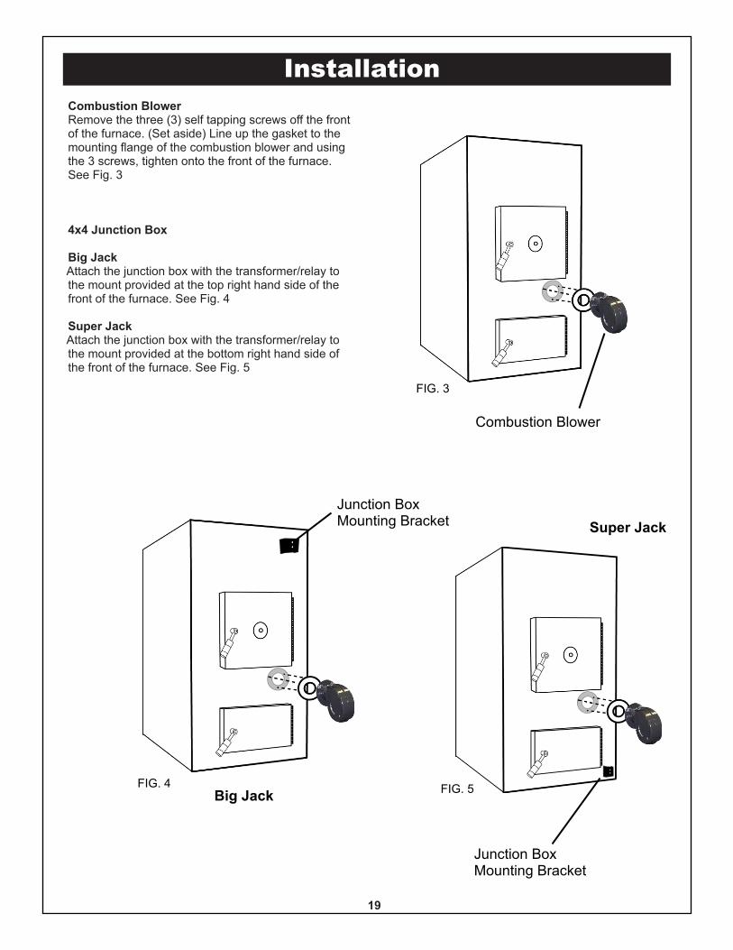
Combustion BlowerRemove the three (3) self tapping screws off the frontof the furnace. (Set aside) Line up the gasket to themounting flange of the combustion blower and usingthe 3 screws, tighten onto the front of the furnace.See Fig. 3
4x4 Junction Box
Big JackAttach the junction box with the transformer/relay tothe mount provided at the top right hand side of thefront of the furnace. See Fig. 4
Super JackAttach the junction box with the transformer/relay tothe mount provided at the bottom right hand side ofthe front of the furnace. See Fig. 5
19
FIG. 3
FIG. 4 FIG. 5
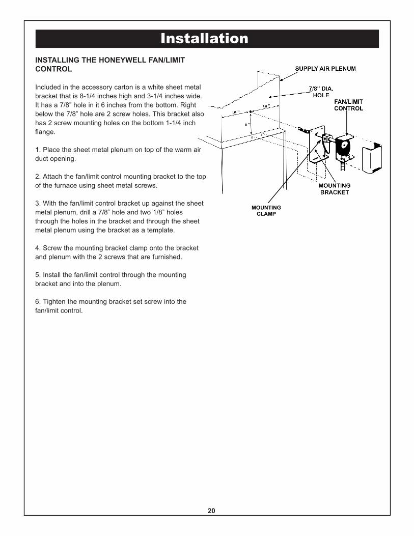
InstallationINSTALLING THE HONEYWELL FAN/LIMITCONTROL
Included in the accessory carton is a white sheet metalbracket that is 8-1/4 inches high and 3-1/4 inches wide.It has a 7/8” hole in it 6 inches from the bottom. Rightbelow the 7/8” hole are 2 screw holes. This bracket alsohas 2 screw mounting holes on the bottom 1-1/4 inchflange.
1. Place the sheet metal plenum on top of the warm airduct opening.
2. Attach the fan/limit control mounting bracket to the topof the furnace using sheet metal screws.
3. With the fan/limit control bracket up against the sheetmetal plenum, drill a 7/8” hole and two 1/8” holesthrough the holes in the bracket and through the sheetmetal plenum using the bracket as a template.
4. Screw the mounting bracket clamp onto the bracketand plenum with the 2 screws that are furnished.
5. Install the fan/limit control through the mountingbracket and into the plenum.
6. Tighten the mounting bracket set screw into thefan/limit control.
20
MOUNTINGCLAMP
Installation
HoneywellDigital
Thermostat
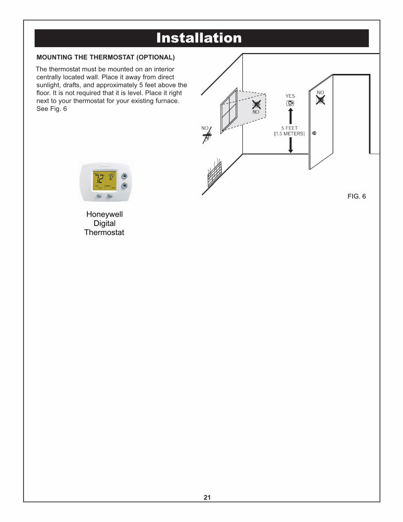
MOUNTING THE THERMOSTAT (OPTIONAL)
The thermostat must be mounted on an interiorcentrally located wall. Place it away from directsunlight, drafts, and approximately 5 feet above thefloor. It is not required that it is level. Place it rightnext to your thermostat for your existing furnace.See Fig. 6
21
FIG. 6
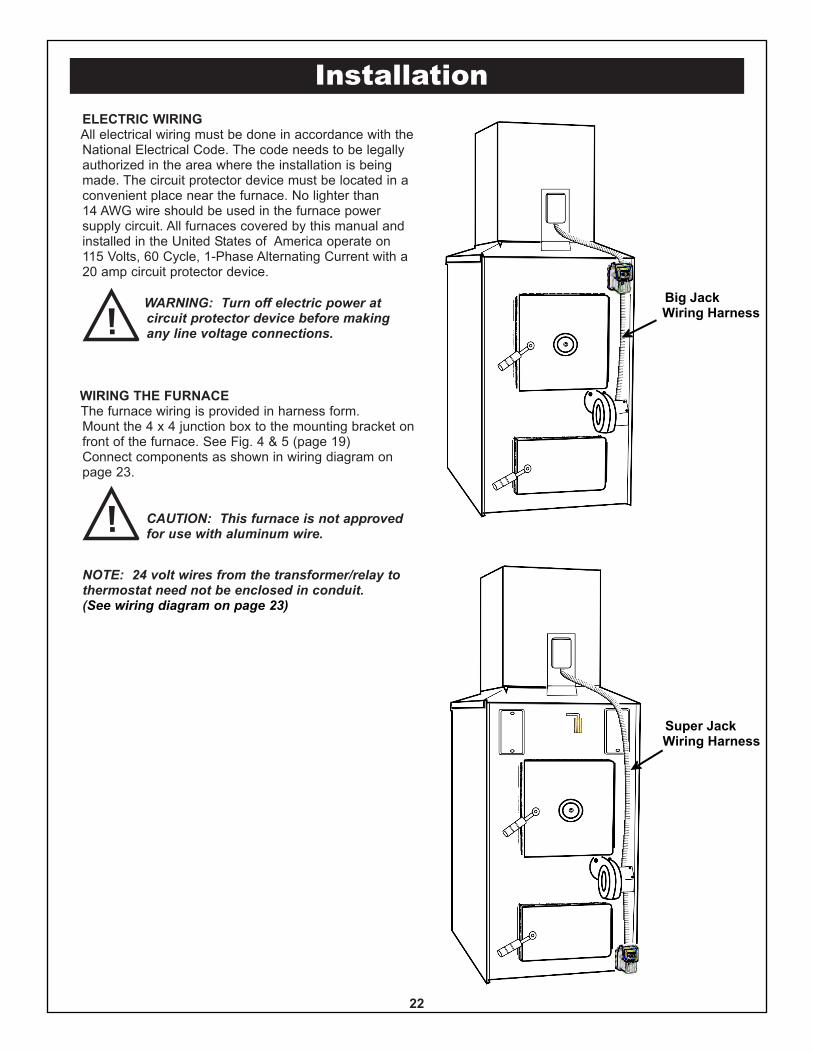
InstallationELECTRIC WIRINGAll electrical wiring must be done in accordance with theNational Electrical Code. The code needs to be legallyauthorized in the area where the installation is beingmade. The circuit protector device must be located in aconvenient place near the furnace. No lighter than14 AWG wire should be used in the furnace powersupply circuit. All furnaces covered by this manual andinstalled in the United States of America operate on115 Volts, 60 Cycle, 1-Phase Alternating Current with a20 amp circuit protector device.
WARNING: Turn off electric power atcircuit protector device before makingany line voltage connections.
WIRING THE FURNACEThe furnace wiring is provided in harness form.Mount the 4 x 4 junction box to the mounting bracket onfront of the furnace. See Fig. 4 & 5 (page 19)Connect components as shown in wiring diagram onpage 23.
CAUTION: This furnace is not approvedfor use with aluminum wire.
NOTE: 24 volt wires from the transformer/relay tothermostat need not be enclosed in conduit.(See wiring diagram on page 23)
22
Big JackWiring Harness
Super JackWiring Harness
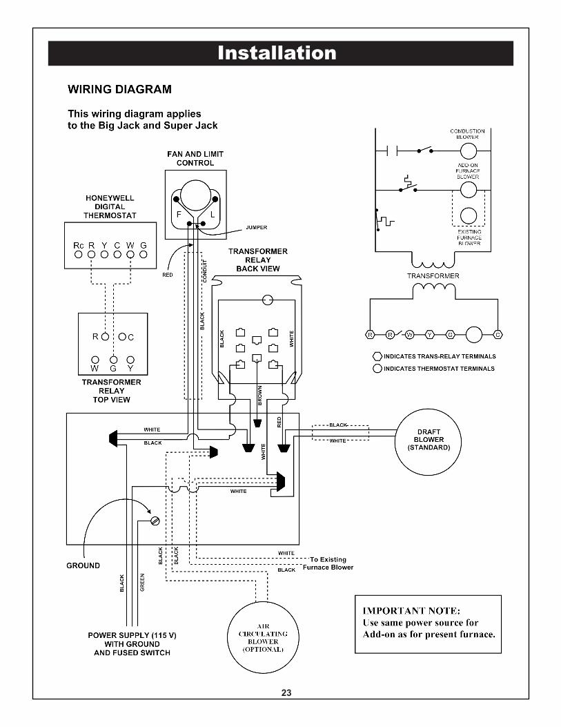
Installation
23
24
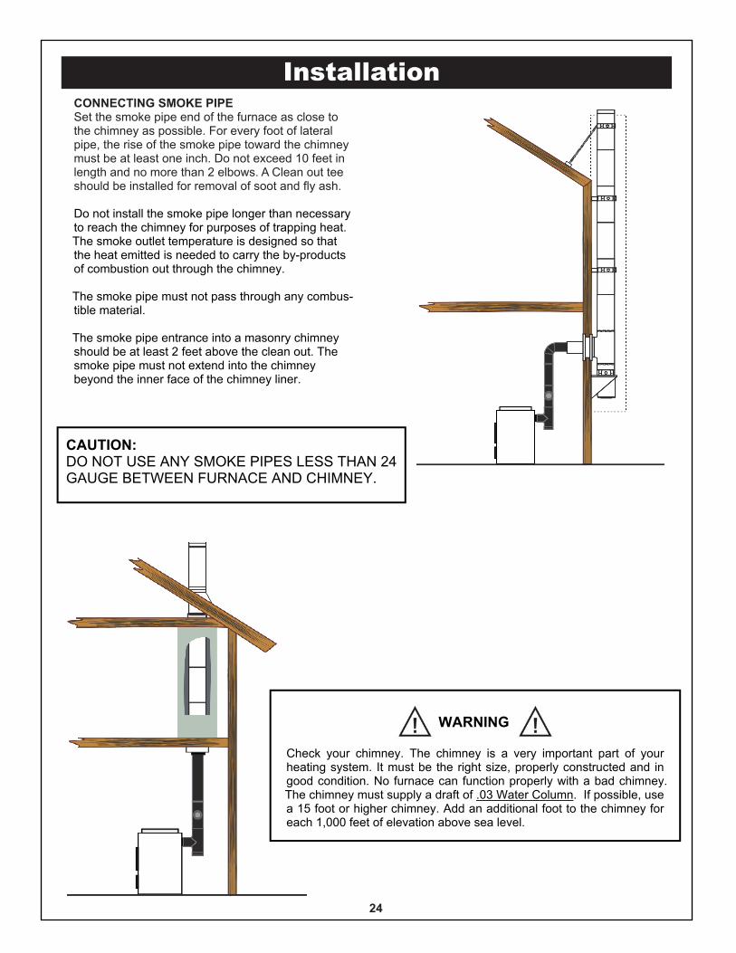
CONNECTING SMOKE PIPESet the smoke pipe end of the furnace as close tothe chimney as possible. For every foot of lateralpipe, the rise of the smoke pipe toward the chimneymust be at least one inch. Do not exceed 10 feet inlength and no more than 2 elbows. A Clean out teeshould be installed for removal of soot and fly ash.
Do not install the smoke pipe longer than necessaryto reach the chimney for purposes of trapping heat.The smoke outlet temperature is designed so thatthe heat emitted is needed to carry the by-productsof combustion out through the chimney.
The smoke pipe must not pass through any combus-tible material.
The smoke pipe entrance into a masonry chimneyshould be at least 2 feet above the clean out. Thesmoke pipe must not extend into the chimneybeyond the inner face of the chimney liner.
CAUTION:DO NOT USE ANY SMOKE PIPES LESS THAN 24GAUGE BETWEEN FURNACE AND CHIMNEY.
WARNING
Check your chimney. The chimney is a very important part of yourheating system. It must be the right size, properly constructed and ingood condition. No furnace can function properly with a bad chimney.The chimney must supply a draft of .03 Water Column. If possible, usea 15 foot or higher chimney. Add an additional foot to the chimney foreach 1,000 feet of elevation above sea level.
Installation
25
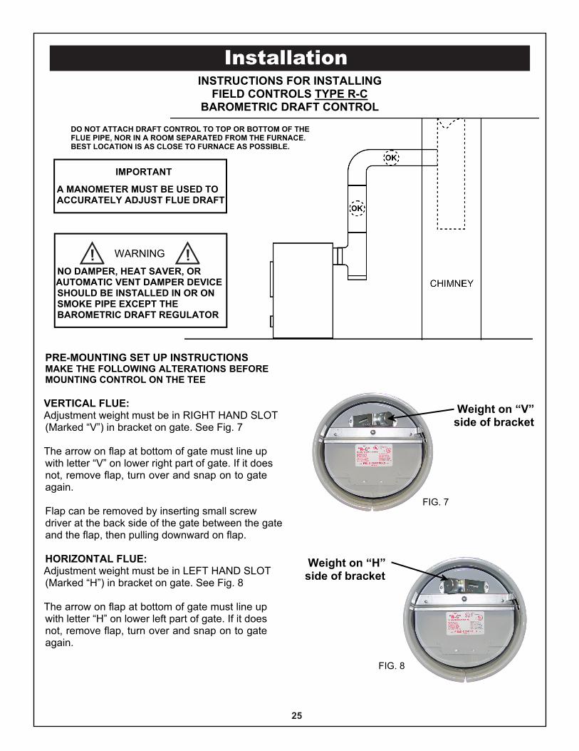
INSTRUCTIONS FOR INSTALLINGFIELD CONTROLS TYPE R-C
BAROMETRIC DRAFT CONTROL
DO NOT ATTACH DRAFT CONTROL TO TOP OR BOTTOM OF THEFLUE PIPE, NOR IN A ROOM SEPARATED FROM THE FURNACE.BEST LOCATION IS AS CLOSE TO FURNACE AS POSSIBLE.
PRE-MOUNTING SET UP INSTRUCTIONSMAKE THE FOLLOWING ALTERATIONS BEFOREMOUNTING CONTROL ON THE TEE
VERTICAL FLUE:Adjustment weight must be in RIGHT HAND SLOT(Marked “V”) in bracket on gate. See Fig. 7
The arrow on flap at bottom of gate must line upwith letter “V” on lower right part of gate. If it doesnot, remove flap, turn over and snap on to gateagain.
Flap can be removed by inserting small screwdriver at the back side of the gate between the gateand the flap, then pulling downward on flap.
HORIZONTAL FLUE:Adjustment weight must be in LEFT HAND SLOT(Marked “H”) in bracket on gate. See Fig. 8
The arrow on flap at bottom of gate must line upwith letter “H” on lower left part of gate. If it doesnot, remove flap, turn over and snap on to gateagain.
Weight on “V”side of bracket
Weight on “H”side of bracket
IMPORTANT
A MANOMETER MUST BE USED TOACCURATELY ADJUST FLUE DRAFT
Installation
FIG. 7
FIG. 8
WARNING
NO DAMPER, HEAT SAVER, ORAUTOMATIC VENT DAMPER DEVICESHOULD BE INSTALLED IN OR ONSMOKE PIPE EXCEPT THEBAROMETRIC DRAFT REGULATOR
26
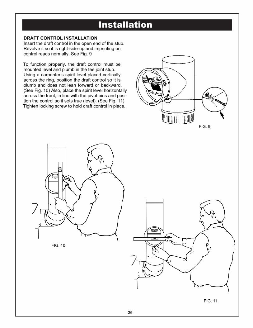
DRAFT CONTROL INSTALLATIONInsert the draft control in the open end of the stub.Revolve it so it is right-side-up and imprinting oncontrol reads normally. See Fig. 9
To function properly, the draft control must bemounted level and plumb in the tee joint stub.Using a carpenter’s spirit level placed verticallyacross the ring, position the draft control so it isplumb and does not lean forward or backward.(See Fig. 10) Also, place the spirit level horizontallyacross the front, in line with the pivot pins and posi-tion the control so it sets true (level). (See Fig. 11)Tighten locking screw to hold draft control in place.
Installation
FIG. 9
FIG. 10
FIG. 11
Installation
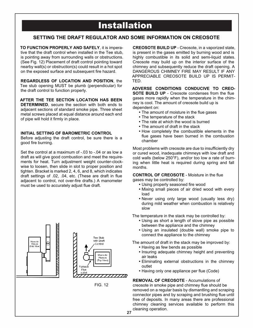
TO FUNCTION PROPERLY AND SAFELY, it is impera-tive that the draft control when installed in the Tee stub,is pointing away from surrounding walls or obstructions.(See Fig. 12) Placement of draft control pointing towardnearby wall(s) or obstruction(s) could result in a hot spoton the exposed surface and subsequent fire hazard.
REGARDLESS OF LOCATION AND POSITION, theTee stub opening MUST be plumb (perpendicular) forthe draft control to function properly.
AFTER THE TEE SECTION LOCATION HAS BEENDETERMINED, secure the section with both ends toadjacent sections of standard smoke pipe. Three sheetmetal screws placed at equal distance around each endof pipe will hold it firmly in place.
INITIAL SETTING OF BAROMETRIC CONTROLBefore adjusting the draft control, be sure there is agood fire burning.
Set the control at a maximum of -.03 to -.04 or as low adraft as will give good combustion and meet the require-ments for heat. Turn adjustment weight counter-clock-wise to loosen, then slide in slot to proper position andtighten. Bracket is marked 2, 4, 6, and 8, which indicatesdraft settings of .02, .04, etc. (These are draft in flueadjacent to control, not over-fire drafts.) A manometermust be used to accurately adjust flue draft.
SETTING THE DRAFT REGULATOR AND SOME INFORMATION ON CREOSOTE
CREOSOTE BUILD UP - Creosote, in a vaporized state,is present in the gases emitted by burning wood and ishighly combustible in its solid and semi-liquid states.Creosote may build up on the interior surface of thechimney and subsequently reduce the draft opening. ADANGEROUS CHIMNEY FIRE MAY RESULT IF ANYAPPRECIABLE CREOSOTE BUILD UP IS PERMIT-TED.
ADVERSE CONDITIONS CONDUCIVE TO CREO-SOTE BUILD UP - Creosote condenses from the fluegases more rapidly when the temperature in the chim-ney is cool. The amount of creosote build up isdependent on:� The amount of moisture in the flue gases� The temperature of the stack� The rate at which the wood is burned� The amount of draft in the stack� How completely the combustible elements in the
flue gases have been burned in the combustionchamber
Most problems with creosote are due to insufficiently dryor cured wood, inadequate chimneys with low draft andcold walls (below 250°F), and/or too low a rate of burn-ing when little heat is required during spring and fallmonths.
CONTROL OF CREOSOTE - Moisture in the fluegases may be controlled by:� Using properly seasoned fire wood� Mixing small pieces of air dried wood with every
load� Never using only large wood (usually less dry)
during mild weather when combustion is relativelyslow
The temperature in the stack may be controlled by:� Using as short a length of stove pipe as possible
between the appliance and the chimney� Using an insulated (double wall) smoke pipe to
connect the appliance to the chimney
The amount of draft in the stack may be improved by:� Having as few bends as possible� Insuring adequate chimney height and preventing
air leaks� Eliminating external obstructions in the chimney
outlet� Having only one appliance per flue (Code)
REMOVAL OF CREOSOTE - Accumulations ofcreosote in smoke pipe and chimney flue should beremoved on a regular basis by dismantling and scrapingconnector pipes and by scraping and brushing flue untilfree of deposits. In many areas there are professionalchimney cleaning services available to perform thiscleaning operation.
27
FIG. 12
Operating Instructions
SpeciesPoundWeight
Per Cord
BTU’sper CordAir Dried
Wood
EquivalentValue #2Fuel OilGallons
Hickory 4,327 27,700,000 198
Apple 4,100 26,500,000 189
White Oak 4,012 25,700,000 184
Beech 3,757 24,000,000 171
Red Oak 3,757 24,000,000 171
Sugar Maple 3,757 24,000,000 171
Yellow Birch 3,689 23,600,000 169
White Ash 3,689 23,600,000 169
Tamarack 3,247 20,800,000 149
Paper Birch 3,179 20,300,000 145
Cherry 3,121 20,000,000 143
Elm 3,052 19,500,000 139
Black Ash 2,992 19,100,000 136
Red Maple 2,924 18,700,000 134
Box Elder 2,797 17,900,000 128
Black Spruce 2,482 15,900,000 114
Ponderosa Pine 2,380 15,200,000 109
Aspen 2,290 14,700,000 105
Cottonwood 2,108 13,500,000 96
BEST WOOD TO BURN
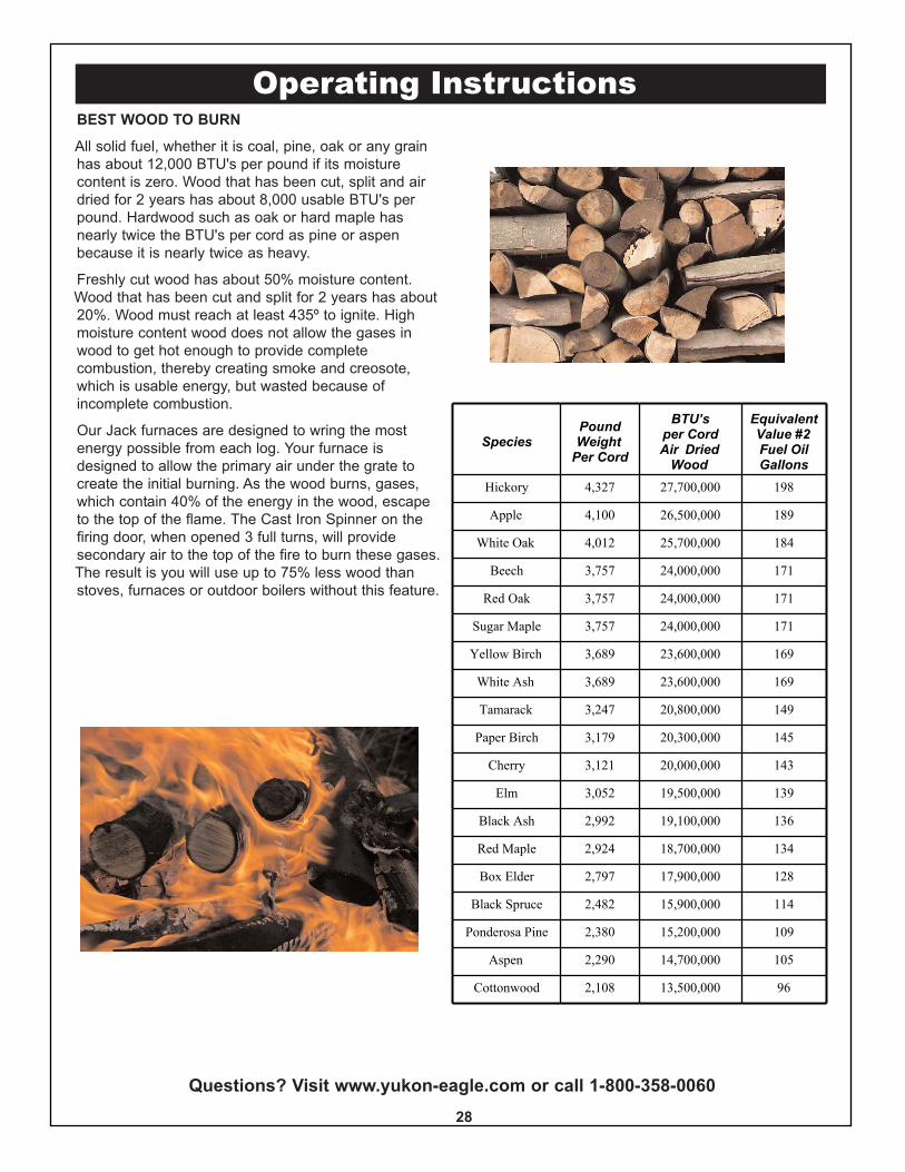
All solid fuel, whether it is coal, pine, oak or any grainhas about 12,000 BTU's per pound if its moisturecontent is zero. Wood that has been cut, split and airdried for 2 years has about 8,000 usable BTU's perpound. Hardwood such as oak or hard maple hasnearly twice the BTU's per cord as pine or aspenbecause it is nearly twice as heavy.
Freshly cut wood has about 50% moisture content.Wood that has been cut and split for 2 years has about20%. Wood must reach at least 435º to ignite. Highmoisture content wood does not allow the gases inwood to get hot enough to provide completecombustion, thereby creating smoke and creosote,which is usable energy, but wasted because ofincomplete combustion.
Our Jack furnaces are designed to wring the mostenergy possible from each log. Your furnace isdesigned to allow the primary air under the grate tocreate the initial burning. As the wood burns, gases,which contain 40% of the energy in the wood, escapeto the top of the flame. The Cast Iron Spinner on thefiring door, when opened 3 full turns, will providesecondary air to the top of the fire to burn these gases.The result is you will use up to 75% less wood thanstoves, furnaces or outdoor boilers without this feature.
Questions? Visit www.yukon-eagle.com or call 1-800-358-006028
Operating InstructionsHELPFUL HINTSSet the draft to proper setting. The chimney, hook-ups, andkinds of wood will be a factor.
Open the disc on the side of the Draft Inducer Motor(supplied with your Jack furnace) to allow air into the furnacefor combustion. While lighting the fire, open disc all the way.Once a good fire is established, adjust the disc back to apoint where you are achieving the desired amount of heatand burn times.
Your Jack is capable of holding very large logs. DO NOT tryto add a log that is larger than what you can easily place inthe furnace. You will get best efficiency when you add onlythe amount of wood needed for a 4 to 6 hour burn.
In the spring and in the fall when the weather is mild, burninglarge loads of wood for long periods may cause creosote.Stack (chimney) temperature should be 300º for good burn-ing. Again, depending on the weather, you may not need afull load of wood for a good overnight burn. You will get thebest efficiency when you add only small amounts of wood.
Let the thermostat and draft inducer blower do their jobs.They should cause a “high burn - low burn” cycle. Do not letthe wood smolder.
You can use wood of various shapes, diameters and lengths,but not to exceed the maximum recommended loadingheight.
Always try to place the logs so air has free flow betweenthem, increasing combustion.
29
CAUTION:DO NOT LOAD WOOD OR COAL HIGHERTHAN THE TOP OF THE FIREBRICKS.Failure or damage to the firebox could result.
STARTING A WOOD FIRE
1. Place several pieces of crumpled paper in the center ofyour firebox. In a criss-cross pattern, place a couple hand-fuls of dry kindling wood 3/4” thickness, then several smalldry pieces of firewood.
NEVER USE CHEMICALS OR FLUIDS SUCH ASGASOLINE, CHARCOAL LIGHTER FLUID, DRAIN OIL ORKEROSENE TO LIGHT A FIRE IN YOUR JACK FURNACE.
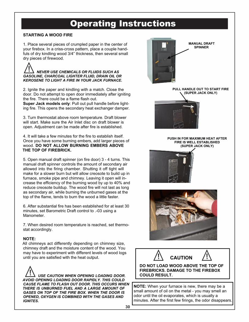
2. Ignite the paper and kindling with a match. Close thedoor. Do not attempt to open door immediately after ignitingthe fire. There could be a flame flash out.Super Jack models only: Pull out pull handle before light-ing fire. This opens the secondary heat exchanger damper.
3. Turn thermostat above room temperature. Draft blowerwill start. Make sure the Air Inlet disc on draft blower isopen. Adjustment can be made after fire is established.
4. It will take a few minutes for the fire to establish itself.Once you have some burning embers, add larger pieces ofwood. DO NOT ALLOW BURNING EMBERS ABOVETHE TOP OF FIREBRICK.
5. Open manual draft spinner (on fire door) 3 - 4 turns. Thismanual draft spinner controls the amount of secondary airallowed into the firing chamber. Shutting it off tight willmake for a slower burn but will allow creosote to build up infurnace, smoke pipe and chimney. Leaving it open will in-crease the efficiency of the burning wood by up to 40% andreduce creosote buildup. The wood fire will not last as longas secondary air, while burning the unburned gases at thetop of the flame, tends to burn the wood a little faster.
6. After substantial fire has been established for at least 30minutes, set Barometric Draft control to .-03 using aManometer.
7. When desired room temperature is reached, set thermo-stat accordingly.
NOTE:All chimneys act differently depending on chimney size,chimney draft and the moisture content of the wood. Youmay have to experiment with different levels of wood logsuntil you are satisfied with the heat output.
USE CAUTION WHEN OPENING LOADING DOOR.AVOID OPENING LOADING DOOR RAPIDLY. THIS COULDCAUSE FLAME TO FLASH OUT DOOR. THIS OCCURS WHENTHERE IS UNBURNED FUEL AND A LARGE AMOUNT OFGASES ON TOP OF THE FIRE BOX. WHEN THE DOOR ISOPENED, OXYGEN IS COMBINED WITH THE GASES ANDIGNITES.
Operating Instructions
PULL HANDLE OUT TO START FIRE(SUPER JACK ONLY)
PUSH IN FOR MAXIMUM HEAT AFTERFIRE IS WELL ESTABLISHED
(SUPER JACK ONLY)
MANUAL DRAFTSPINNER
NOTE: When your furnace is new, there may be asmall amount of oil on the metal - you may smell anodor until the oil evaporates, which is usually aminutes. After the first few firings, the odor disappears.
30
CAUTIONDO NOT LOAD WOOD ABOVE THE TOP OFFIREBRICKS. DAMAGE TO THE FIREBOXCOULD RESULT.
Questions? Visit www.yukon-eagle.com or call 1-800-358-0060
OPERATING INSTRUCTIONS FOR BURNING COALON 1/2-INCH OPENING GRATES (Optional)
The following instructions are for burning various typesof coal, storage of coal, and the cleaning of the furnace.
Some coal is oil-treated at the mine. Some users haveindicated that it tends to make the coal difficult to start.
Burning coal requires some patience and a regularprocedure. With improper tending, a coal fire can go outin a short time. Once the fire starts to go out, it is almostimpossible to reverse.
After a coal fire goes out, the coal must be removedfrom furnace. Then the starting process can berepeated.
Our coal burning instructions are general, as coalcomes in various sizes and types. Anthracite coal ismost recommended as it burns with little smoke whenburning properly.
CAUTION: Burn Anthracite or Bituminous coalsonly. DO NOT BURN Petroleum, Coke, orCannel Coals.
IGNITION TEMPERATURE OF COAL AND WOODHow hot does coal have to get to ignite? Following areexamples of the ignition points of variousmaterials:
• Paper ignites @: 350°F
• Wood ignites @: 435°F
• Western lignite ignites @: 630°F
• Low volatile bituminous ignites @: 765°F
• High volatile bituminous ignites @: 870°F
• Anthracite coal ignites @: 925°F
Operating Instructions
31
STORAGE OF COALCoal may be stored indoors or outdoors, with someprecautions:
1. The storage area must be free of materials that areeasily burned. Examples are paper, wood, rags, andleaves.
2. Wetting and drying of coal should be avoided.Outside storage's should be protected from rain orsnow. Wet coal should not be piled on dry coal.
3. Locate the storage area in a place that is 75º F orlower.
4. Nut coal weighs approximately 58 lbs. per cu. ft. Astorage bin 4-feet square by 4-feet high will hold 2 tons.
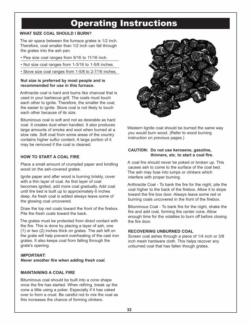
WHAT SIZE COAL SHOULD I BURN?
The air space between the furnace grates is 1/2 inch.Therefore, coal smaller than 1/2 inch can fall throughthe grates into the ash pan.
• Pea size coal ranges from 9/16 to 11/16 inch.
• Nut size coal ranges from 1-3/16 to 1-5/8 inches.
• Stove size coal ranges from 1-5/8 to 2-7/16 inches.
Nut size is preferred by most people and isrecommended for use in this furnace.
Anthracite coal is hard and burns like charcoal that isused in your barbecue grill. The coals must toucheach other to ignite. Therefore, the smaller the coal,the easier to ignite. Stove coal is not likely to toucheach other because of its size.
Bituminous coal is soft and not as desirable as hardcoal. It creates dust when handled. It also produceslarge amounts of smoke and soot when burned at aslow rate. Soft coal from some areas of the countrycontains higher sulfur content. A large portion of itmay be removed if the coal is cleaned.
HOW TO START A COAL FIRE
Place a small amount of crumpled paper and kindlingwood on the ash-covered grates.
Ignite paper and after wood is burning briskly, coverwith a thin layer of coal. As first layer of coalbecomes ignited, add more coal gradually. Add coaluntil fire bed is built up to approximately 6 inchesdeep. As fresh coal is added always leave some ofthe glowing coal uncovered.
Draw the top red coals toward the front of the firebox.Pile the fresh coals toward the back.
The grates must be protected from direct contact withthe fire. This is done by placing a layer of ash, one(1) or two (2) inches thick on grates. The ash left onthe grate will help prevent overheating of the cast irongrates. It also keeps coal from falling through thegrate's opening.
IMPORTANT:Never smother fire when adding fresh coal.
MAINTAINING A COAL FIRE
Bituminous coal should be built into a cone shapeonce the fire has started. When refiring, break up thecone a little using a poker. Especially if it has cakedover to form a crust. Be careful not to mix the coal asthis increases the chance of forming clinkers.
Western lignite coal should be burned the same wayyou would burn wood. (Refer to wood burninginstruction on previous pages.)
CAUTION: Do not use kerosene, gasoline,thinners, etc. to start a coal fire.
A coal fire should never be poked or broken up. Thiscauses ash to come to the surface of the coal bed.The ash may fuse into lumps or clinkers whichinterfere with proper burning.
Anthracite Coal - To bank the fire for the night, pile thecoal higher to the back of the firebox. Allow it to slopetoward the fire box door. Always leave some red orburning coals uncovered in the front of the firebox.
Bituminous Coal - To bank fire for the night, shake thefire and add coal, forming the center cone. Allowenough time for the volatiles to burn off before closingthe fire door.
RECOVERING UNBURNED COALScreen coal ashes through a piece of 1/4 inch or 3/8inch mesh hardware cloth. This helps recover anyunburned coal that has fallen though grates.
Operating Instructions
32
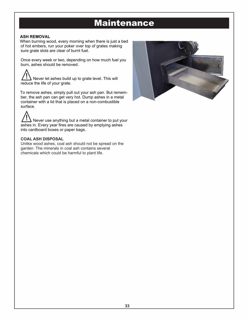
MaintenanceASH REMOVALWhen burning wood, every morning when there is just a bedof hot embers, run your poker over top of grates makingsure grate slots are clear of burnt fuel.
Once every week or two, depending on how much fuel youburn, ashes should be removed.
Never let ashes build up to grate level. This willreduce the life of your grate.
To remove ashes, simply pull out your ash pan. But remem-ber, the ash pan can get very hot. Dump ashes in a metalcontainer with a lid that is placed on a non-combustiblesurface.
Never use anything but a metal container to put yourashes in. Every year fires are caused by emptying ashesinto cardboard boxes or paper bags.
COAL ASH DISPOSALUnlike wood ashes, coal ash should not be spread on thegarden. The minerals in coal ash contains severalchemicals which could be harmful to plant life.
33
Maintenance
34
FAULTY CHIMNEY AND/OR DRAFT PROBLEMS -CAUSES AND CURESA sound chimney system is imperative, especially when burning wood. Indoor chimney, either masonry or type“HT” metal chimneys are the best. Because warm air rises, a warm chimney allows the smoke and otherby-products of combustion a natural exit up and out the chimney. Outdoor chimneys should be your last choice.Cold air naturally falls right down the cold chimney. Until the heat from the furnace warms the chimney, thereis no natural draft to allow the smoke and by-products of combustion to rise naturally up the chimney. OutdoorClass “A” Triple Wall is not acceptable because their thermo-siphon design will not allow the chimney to heatup, causing heavy creosote build-up and possible chimney fires.
If you know your chimney is sound and you still have downdraft problems such as smoke or smell in the roomin which the furnace is located, your chimney may not be operating properly. One or more of the followingsuggestions may be necessary.
1. Barometric draft control - This control must be set at -.03. This is just a guide. It must be set with adraft gauge to prove that the chimney is drawing .03.
2. Combustion air - You must have outdoor combustion air introduced into the room where the furnaceresides in the manner described on page 17. This method supplies air for combustion as well asreplacing air that is drawn out by the chimney. Leaky doors and windows will not provide acceptableresults.
3. Cold outdoor chimney - Sometimes in the spring or fall, or if you live in a mild climate, your heatdemands are small and your chimney just does not heat up enough to induce a natural exit up draft,you may want to consider a power vent to force a draft up the chimney. A Model D-3 or AD-1 powerventer is available from Tjurnland Manufacturing Co. in White Bear Lake, Minnesota or Model D1-2 isavailable from Field Controls Co., Kinston, North Carolina.
4. Chimney not tall enough - Your chimney must terminate at least 2 feet above the peak of the roof.Adding more chimney height sometimes cures the problem. See page 15.
5. Home located on side of hill - When the wind blows over a hill toward your home, the wind will fall.This could cause a down-draft into your chimney. Some common solutions to correct down-drafts areto add a chimney cap with a weather vane, add height to the chimney or add a power venter.
6. Tall trees near your home - If you have trees that are near to and higher than your home, a down-draftcan occur when the wind blows. Correct the same way as if you live on the side of a hill or in a valley.
7. Chimney too large - Your chimney should not be more than 8 inches in diameter or the equivalent. Iftoo large, the sides of the chimney may not heat up to create a natural draft. When this happens, thesmoke and gases cool . They become heavy and other gases from the fire try to penetrate this heavycolumn of cool air. This results in back puffing, poor combustion or burning and may cause odors inyour home. The solution is to improve your chimney or line it with 8-inch type 304 stainless steel flueliner. If your large chimney is outside masonry, insulate between the masonry and 8-inch flue pipe.
Maintenance
35
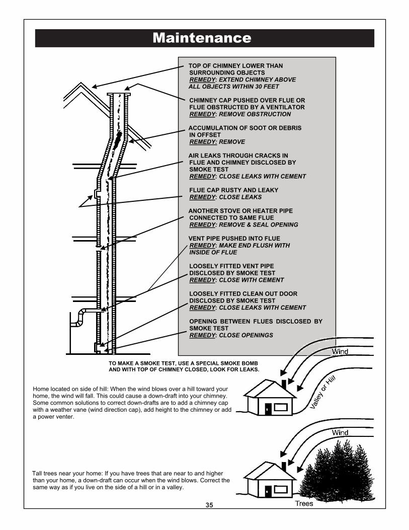
TOP OF CHIMNEY LOWER THANSURROUNDING OBJECTSREMEDY: EXTEND CHIMNEY ABOVEALL OBJECTS WITHIN 30 FEET
CHIMNEY CAP PUSHED OVER FLUE ORFLUE OBSTRUCTED BY A VENTILATORREMEDY: REMOVE OBSTRUCTION
ACCUMULATION OF SOOT OR DEBRISIN OFFSETREMEDY: REMOVE
AIR LEAKS THROUGH CRACKS INFLUE AND CHIMNEY DISCLOSED BYSMOKE TESTREMEDY: CLOSE LEAKS WITH CEMENT
FLUE CAP RUSTY AND LEAKYREMEDY: CLOSE LEAKS
ANOTHER STOVE OR HEATER PIPECONNECTED TO SAME FLUEREMEDY: REMOVE & SEAL OPENING
VENT PIPE PUSHED INTO FLUEREMEDY: MAKE END FLUSH WITHINSIDE OF FLUE
LOOSELY FITTED VENT PIPEDISCLOSED BY SMOKE TESTREMEDY: CLOSE WITH CEMENT
LOOSELY FITTED CLEAN OUT DOORDISCLOSED BY SMOKE TESTREMEDY: CLOSE LEAKS WITH CEMENT
OPENING BETWEEN FLUES DISCLOSED BYSMOKE TESTREMEDY: CLOSE OPENINGS
TO MAKE A SMOKE TEST, USE A SPECIAL SMOKE BOMBAND WITH TOP OF CHIMNEY CLOSED, LOOK FOR LEAKS.
Home located on side of hill: When the wind blows over a hill toward yourhome, the wind will fall. This could cause a down-draft into your chimney.Some common solutions to correct down-drafts are to add a chimney capwith a weather vane (wind direction cap), add height to the chimney or adda power venter.
Tall trees near your home: If you have trees that are near to and higherthan your home, a down-draft can occur when the wind blows. Correct thesame way as if you live on the side of a hill or in a valley.
36
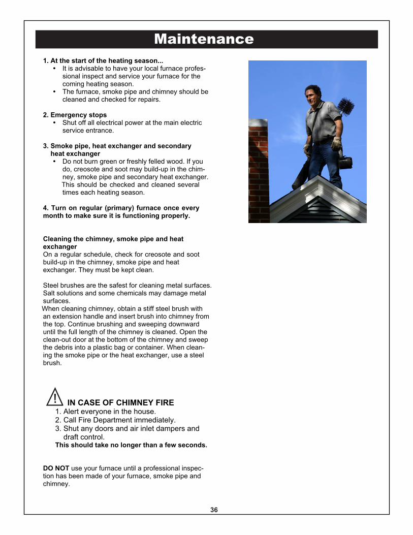
Maintenance1. At the start of the heating season...� It is advisable to have your local furnace profes-
sional inspect and service your furnace for thecoming heating season.
� The furnace, smoke pipe and chimney should becleaned and checked for repairs.
2. Emergency stops� Shut off all electrical power at the main electric
service entrance.
3. Smoke pipe, heat exchanger and secondary heat exchanger� Do not burn green or freshly felled wood. If you
do, creosote and soot may build-up in the chim-ney, smoke pipe and secondary heat exchanger.This should be checked and cleaned severaltimes each heating season.
4. Turn on regular (primary) furnace once everymonth to make sure it is functioning properly.
Cleaning the chimney, smoke pipe and heatexchangerOn a regular schedule, check for creosote and sootbuild-up in the chimney, smoke pipe and heatexchanger. They must be kept clean.
Steel brushes are the safest for cleaning metal surfaces.Salt solutions and some chemicals may damage metalsurfaces.When cleaning chimney, obtain a stiff steel brush withan extension handle and insert brush into chimney fromthe top. Continue brushing and sweeping downwarduntil the full length of the chimney is cleaned. Open theclean-out door at the bottom of the chimney and sweepthe debris into a plastic bag or container. When clean-ing the smoke pipe or the heat exchanger, use a steelbrush.
IN CASE OF CHIMNEY FIRE1. Alert everyone in the house.
2. Call Fire Department immediately. 3. Shut any doors and air inlet dampers and draft control.
This should take no longer than a few seconds.
DO NOT use your furnace until a professional inspec-tion has been made of your furnace, smoke pipe andchimney.

Notes
Exploded Views & Parts List
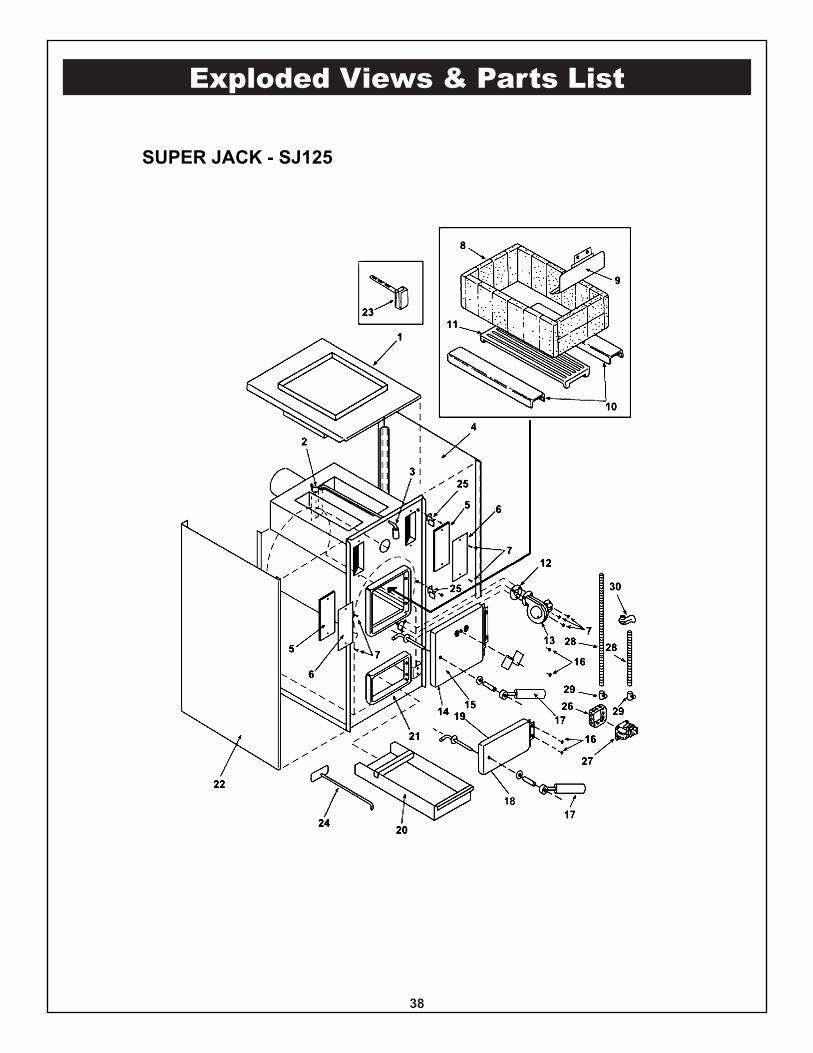
SUPER JACK - SJ125
38
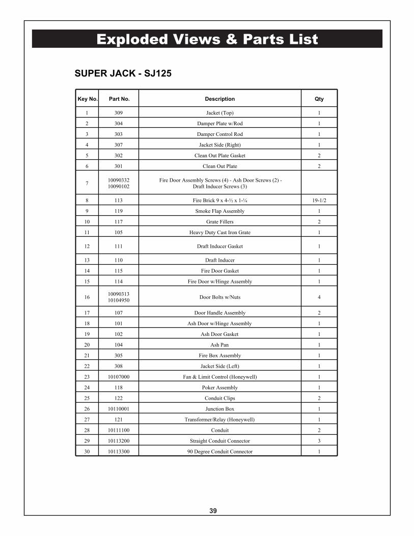
Key No. Part No. Description Qty
1 309 Jacket (Top) 1
2 304 Damper Plate w/Rod 1
3 303 Damper Control Rod 1
4 307 Jacket Side (Right) 1
5 302 Clean Out Plate Gasket 2
6 301 Clean Out Plate 2
7 1009033210090102
Fire Door Assembly Screws (4) - Ash Door Screws (2) -Draft Inducer Screws (3)
8 113 Fire Brick 9 x 4-½ x 1-¼ 19-1/2
9 119 Smoke Flap Assembly 1
10 117 Grate Fillers 2
11 105 Heavy Duty Cast Iron Grate 1
12 111 Draft Inducer Gasket 1
13 110 Draft Inducer 1
14 115 Fire Door Gasket 1
15 114 Fire Door w/Hinge Assembly 1
16 1009031310104950 Door Bolts w/Nuts 4
17 107 Door Handle Assembly 2
18 101 Ash Door w/Hinge Assembly 1
19 102 Ash Door Gasket 1
20 104 Ash Pan 1
21 305 Fire Box Assembly 1
22 308 Jacket Side (Left) 1
23 10107000 Fan & Limit Control (Honeywell) 1
24 118 Poker Assembly 1
25 122 Conduit Clips 2
26 10110001 Junction Box 1
27 121 Transformer/Relay (Honeywell) 1
28 10111100 Conduit 2
29 10113200 Straight Conduit Connector 3
30 10113300 90 Degree Conduit Connector 1
Exploded Views & Parts List
SUPER JACK - SJ125
39
Exploded Views & Parts List
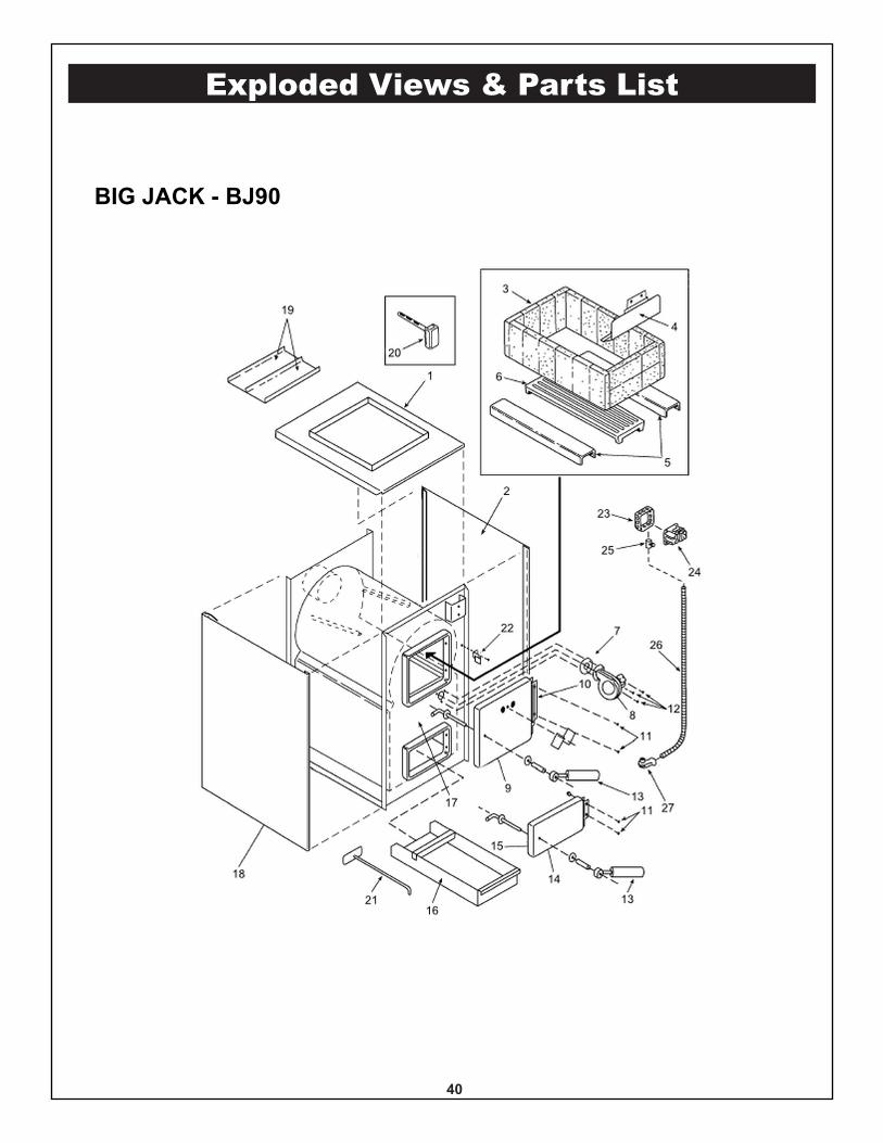
BIG JACK - BJ90
40
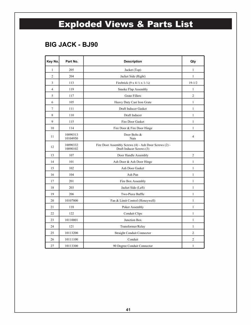
Exploded Views & Parts List
Key No. Part No. Description Qty
1 205 Jacket (Top) 1
2 204 Jacket Side (Right) 1
3 113 Firebrick (9 x 4-½ x 1-¼) 19-1/2
4 119 Smoke Flap Assembly 1
5 117 Grate Fillers 2
6 105 Heavy Duty Cast Iron Grate 1
7 111 Draft Inducer Gasket 1
8 110 Draft Inducer 1
9 115 Fire Door Gasket 1
10 114 Fire Door & Fire Door Hinge 1
11 1009031310104950
Door Bolts &Nuts 4
12 1009033210090102
Fire Door Assembly Screws (4) - Ash Door Screws (2) -Draft Inducer Screws (3)
13 107 Door Handle Assembly 2
14 101 Ash Door & Ash Door Hinge 1
15 102 Ash Door Gasket 1
16 104 Ash Pan 1
17 201 Fire Box Assembly 1
18 203 Jacket Side (Left) 1
19 206 Two-Piece Baffle 1
20 10107000 Fan & Limit Control (Honeywell) 1
21 118 Poker Assembly 1
22 122 Conduit Clips 1
23 10110001 Junction Box 1
24 121 Transformer/Relay 1
25 10113200 Straight Conduit Connector 2
26 10111100 Conduit 2
27 10113300 90 Degree Conduit Connector 1
BIG JACK - BJ90
41
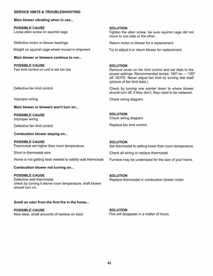
SERVICE HINTS & TROUBLESHOOTING
Main blower vibrating when in use...
POSSIBLE CAUSELoose allen screw on squirrel cage
Defective motor or blower bearings
Weight on squirrel cage wheel moved in shipment
Main blower or blowers continue to run...
POSSIBLE CAUSEFan limit control on unit is set too low
Defective fan limit control
Improper wiring
Main blower or blowers won’t turn on...
POSSIBLE CAUSEImproper wiring
Defective fan limit control
Combustion blower staying on...
POSSIBLE CAUSEThermostat set higher than room temperature.
Short in thermostat wire
Home is not getting heat needed to satisfy wall thermostat
Combustion blower not turning on...
POSSIBLE CAUSEDefective wall thermostat;check by turning it above room temperature, draft blowershould turn on.
Smell an odor from the first fire in the home...
POSSIBLE CAUSENew steel, small amounts of residue on steel
SOLUTIONTighten the allen screw, be sure squirrel cage did notmove to one side or the other.
Return motor or blower for a replacement.
Try to adjust it or return blower for replacement.
SOLUTIONRemove cover on fan limit control and set dials to theproper settings. Recommended temps: 160º on — 130ºoff. NOTE: Never adjust fan limit by turning dial itself(picture of fan limit dials.)
Check by turning one pointer down to where blowershould turn off, if they don’t, they need to be replaced.
Check wiring diagram.
SOLUTIONCheck wiring diagram.
Replace fan limit control.
SOLUTIONSet thermostat to setting lower than room temperature.
Check all wiring or replace thermostat
Furnace may be undersized for the size of your home.
SOLUTIONReplace thermostat or combustion blower motor.
SOLUTIONThis will disappear in a matter of hours.
42
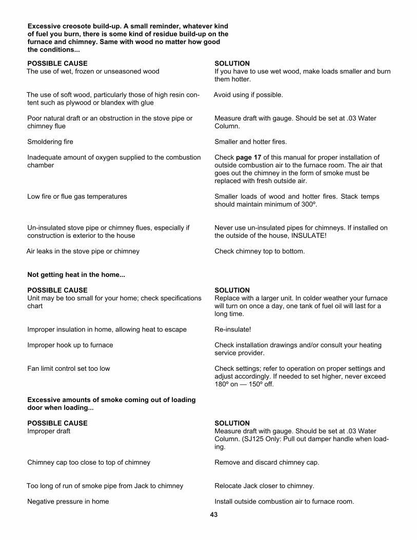
POSSIBLE CAUSEThe use of wet, frozen or unseasoned wood
The use of soft wood, particularly those of high resin con-tent such as plywood or blandex with glue
Poor natural draft or an obstruction in the stove pipe orchimney flue
Smoldering fire
Inadequate amount of oxygen supplied to the combustionchamber
Low fire or flue gas temperatures
Un-insulated stove pipe or chimney flues, especially ifconstruction is exterior to the house
Air leaks in the stove pipe or chimney
Not getting heat in the home...
POSSIBLE CAUSEUnit may be too small for your home; check specificationschart
Improper insulation in home, allowing heat to escape
Improper hook up to furnace
Fan limit control set too low
Excessive amounts of smoke coming out of loadingdoor when loading...
POSSIBLE CAUSEImproper draft
Chimney cap too close to top of chimney
Too long of run of smoke pipe from Jack to chimney
Negative pressure in home
SOLUTIONIf you have to use wet wood, make loads smaller and burnthem hotter.
Avoid using if possible.
Measure draft with gauge. Should be set at .03 WaterColumn.
Smaller and hotter fires.
Check page 17 of this manual for proper installation ofoutside combustion air to the furnace room. The air thatgoes out the chimney in the form of smoke must bereplaced with fresh outside air.
Smaller loads of wood and hotter fires. Stack tempsshould maintain minimum of 300º.
Never use un-insulated pipes for chimneys. If installed onthe outside of the house, INSULATE!
Check chimney top to bottom.
SOLUTIONReplace with a larger unit. In colder weather your furnacewill turn on once a day, one tank of fuel oil will last for along time.
Re-insulate!
Check installation drawings and/or consult your heatingservice provider.
Check settings; refer to operation on proper settings andadjust accordingly. If needed to set higher, never exceed180º on — 150º off.
SOLUTIONMeasure draft with gauge. Should be set at .03 WaterColumn. (SJ125 Only: Pull out damper handle when load-ing.
Remove and discard chimney cap.
Relocate Jack closer to chimney.
Install outside combustion air to furnace room.
Excessive creosote build-up. A small reminder, whatever kindof fuel you burn, there is some kind of residue build-up on thefurnace and chimney. Same with wood no matter how goodthe conditions...
43

Notes

Notes

Notes

Notes

OWNER’SMANUAL
ASSEMBLY INSTALLATION OPERATION REPAIR PARTS
MODEL NUMBERSBJ90 AND SJ125
CAUTION:Read Rules and InstructionsCarefully for Safe Operation
IMPORTANT:Installation must be made inaccordance with State andLocal Ordinances which maydiffer from this InstallationManual.
SUPER JACK & BIG JACKWOOD BURNING FURNACES
ALPHA AMERICAN CO., 10 INDUSTRIAL BLVD., PALISADE, MN 56469www.yukon-eagle.com
HOW TO ORDER REPAIR PARTS
WHEN ORDERING REPAIR PARTS,ALWAYS GIVE THE FOLLOWING INFORMATION:
� MODEL NUMBER
� PART NUMBER
� PART DESCRIPTION
� NAME OF ITEM
Our service technicians will help you... Give us a call!
ALL PARTS MAY BE PURCHASED FROM ANYHEATING CONTRACTOR, OR DIRECT FROM THE FACTORY.
PHONE: 1-800-358-0060
FAX: 1-800-440-1994
EMAIL: [email protected]
WEB SITE: www.yukon-eagle.com