Embed Size (px)
Citation preview

507245-A
THANKS FOR READING THIS MANUAL. IF YOU HAVE ANY DOUBT REGARDING THE
OPERATION OF THIS MEAT SAW, PLEASE CONTACT TO YOUR JR AUTHORIZED DEALER.
GRACIAS POR LEER ESTE MANUAL. SI UD. TIENE ALGUNA DUDA SOBRE LA OPERACIÓN DE
ESTA SIERRA PARA CARNE, POR FAVOR CONTACTE A SU DISTRIBUIDOR JR AUTORIZADO
READ THIS MANUAL BEFORE USING THE EQUIPMENT FOR THE FIRST TIME
LEA LAS INSTRUCCIONES ANTES DE USAR
EL EQUIPO POR PRIMERA VEZ
Owner´s manual/Manual de usuario
MODELOS: SJ-295
OPERATION INSTRUCTIONS
INSTRUCCIONES DE OPERACIÓN
Owner´s manual
1
ENGLISH
I.- INTRODUCTION:
Congratulations!, you have acquired a Meat Saw, which is made of high quality long lasting materials
that should give you years of trouble free operation and durable service. Before you unpack your new
band saw, please, read completely this manual.
IMPORTANT!: it is of vital importance that you or any person that will operate this unit thoroughly read
this manual.
CONTENTS: PAGE
I. INTRODUCTION 1
II. UNPACKING 2
III. INSTALLATION 2
IV. OPERATION 4
V. KEY ELEMENTS IN CUTTING QUALITY PRODUCT 5
VI. CLEANING 5
VII. MAINTENANCE 7
VIII. EQUIPMENT SPECIFICATIONS 8
IX. ELECTRICAL DIAGRAM 9
X. ELECTROMAGNETIC BRAKE (SOME MODELS ONLY) 10
WARNING!:This machine is designed to cut food products and is by nature dangerous, if
not used and maintained properly for optimum safety.
This equipment must be connected to a thermal connection, not use the equipment if it is not properly
grounded.
The appliance is not be used by persons (including children) with
reduced physical, sensory or mental capabilities, or lack of experience
and knowledge, unless they have given supervision or instruction.
Children being supervised not play with the appliance.
Never perform service, cleaning or maintenance on this unit while
connected to a power source.
Never use hands or fingers to feed products to cut; or introduce hands
in to the blade track area, within 4 " ( four inches ) close to the blade,
while in operation.
Do not leave the machine unattended while in operation & turn it off
when it is not being used.
OPERATION INSTRUCTIONS
11
Manual de Usuario
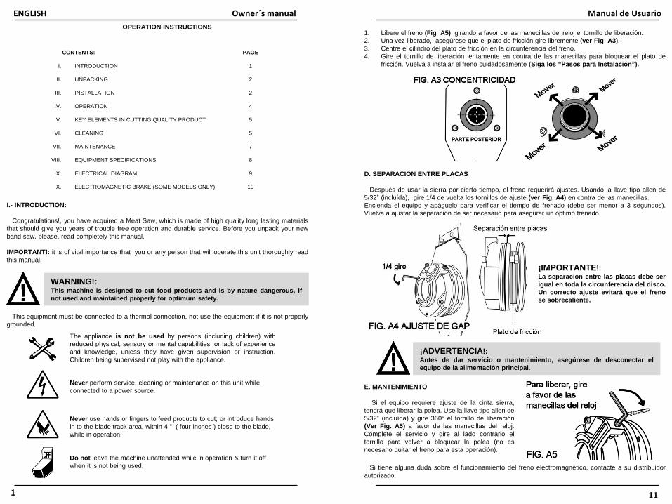
1. Libere el freno (Fig A5) girando a favor de las manecillas del reloj el tornillo de liberación.
2. Una vez liberado, asegúrese que el plato de fricción gire libremente (ver Fig A3).
3. Centre el cilindro del plato de fricción en la circunferencia del freno.
4. Gire el tornillo de liberación lentamente en contra de las manecillas para bloquear el plato de
fricción. Vuelva a instalar el freno cuidadosamente (Siga los “Pasos para Instalación”).
D. SEPARACIÓN ENTRE PLACAS
Después de usar la sierra por cierto tiempo, el freno requerirá ajustes. Usando la llave tipo allen de
5/32” (incluída), gire 1/4 de vuelta los tornillos de ajuste (ver Fig. A4) en contra de las manecillas.
Encienda el equipo y apáguelo para verificar el tiempo de frenado (debe ser menor a 3 segundos).
Vuelva a ajustar la separación de ser necesario para asegurar un óptimo frenado.
E. MANTENIMIENTO
Si el equipo requiere ajuste de la cinta sierra,
tendrá que liberar la polea. Use la llave tipo allen de
5/32” (incluída) y gire 360° el tornillo de liberación
(Ver Fig. A5) a favor de las manecillas del reloj.
Complete el servicio y gire al lado contrario el
tornillo para volver a bloquear la polea (no es
necesario quitar el freno para esta operación).
¡ADVERTENCIA!:Antes de dar servicio o mantenimiento, asegúrese de desconectar el
equipo de la alimentación principal.
Si tiene alguna duda sobre el funcionamiento del freno electromagnético, contacte a su distribuidor
autorizado.
¡IMPORTANTE!:La separación entre las placas debe ser
igual en toda la circunferencia del disco.
Un correcto ajuste evitará que el freno
se sobrecaliente.

Owner´s manual
2
II.- UNPACKING
While unpacking the machine take special care in removing these components to be assembled later.
Make sure that all are accounted for *.
1 spare band saw (6) 1 Last Cut Pusher (40 - some models only)
1 spare fiber guide (17) 4 Rubber legs (33 - some models only)
1 scrap pan (26)
1 carriage (8)
1 table assembly (5)
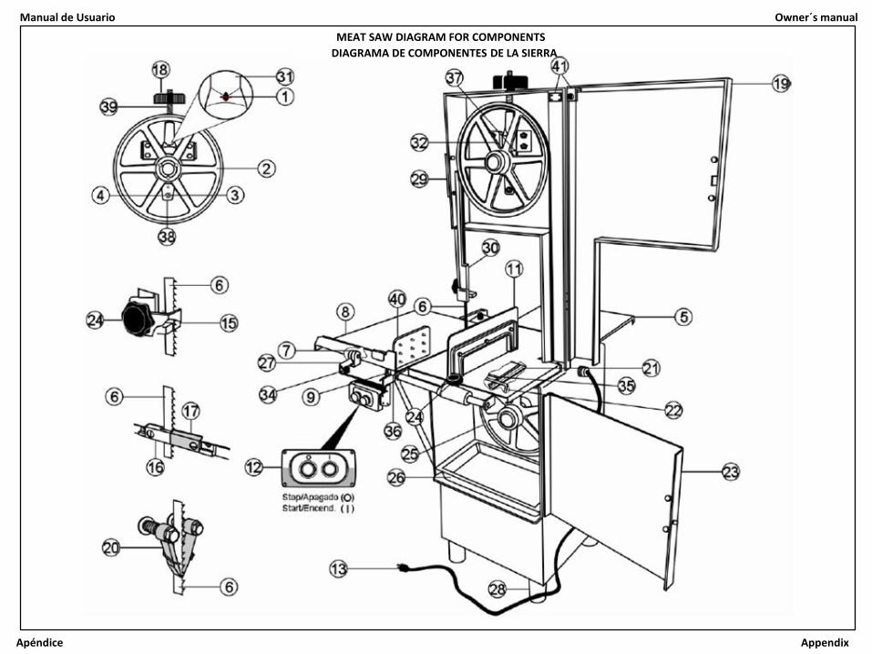
*Note: for reference numbers see “Meat saw diagram for components” (central pages).
III.- INSTALLATION:
Before connecting to the power source follow these easy assembly and preparation steps. (Never
execute these procedures with the cord plugged to the power source).
1.- Set the saw on a clean and level floor, using the leveling legs (28)
2.- Be sure that the pulleys (2 & 25) and blade (6) run free of objects.
3.- It is possible to assemble the table (5) directly, but in order to avoid blade (6) damage, we suggest to
remove it, to do this, follow these easy steps.
A.- Open the head door (19) and the lower ( right ) door (23).
B.- Rotate-up the fiber or Zytel guide (17) (see fig. 1).
C.- Turn the tension handle (18) counter clock wise, until blade (6) is lose.
D.- Pull out the blade from the wheels (2 & 25), guides (15, 16 & 17) and scrapers (20).
4.- Now you can Install the table assy. (5), following these steps (see fig. 2):
A.- Be sure that the head door (19) and the right door (23) are still open.
10
Manual de Usuario
X.- FRENO ELECTROMAGNÉTICO (ALGUNOS MODELOS DE SIERRA):
Dependiendo del equipamiento de su
sierra, podrá traer instalado de linea un freno
electromagnético (ver Fig A1). Si es así, lea
la siguiente información adicional.
El freno es instalado en el sistema de
transmisión de la sierra. Éste detiene el motor
y a su vez a la cinta sierra en menos de 3
segundos.
A. OPERACIÓN
La polea de la cinta sierra queda bloqueada
cuando el equipo está apagado. Cuando éste
se enciende, el freno es desactivado liberándo
la transmisión y entonces la polea podrá girar.
Si usted apaga el equipo, el freno se activará
de nueva cuenta bloqueando la transmisión y
el motor se parará inmediatamente.
B. CONEXIONES ELÉCTRICAS
El freno es conectado a la caja de control a través de un rectificador (Ver Fig A2).
C. PASOS PARA LA DESINSTALACIÓN
1. Desconecte el equipo. Localice el freno instalado en el sistema de transmisión.
2. Desatornille la placa soporte para freno.
3. Jale el ensamble completo (Base y Freno).
D. PASOS PARA LA INSTALACIÓN
1. Verifique la concentricidad entre la placa de fricción y la placa posterior (Ver Fig A3) antes de
ensamblar el freno. Refiérase a la sección “Centrado de placa de fricción” .
2. Si es necesario ajuste la separación entre placas (vea “Separación entre placas”).
3. Ensamble el freno en la flecha de la polea asegurándo la alineación de las caras (flecha y
engrane).
4. Atornille la placa soporte y el freno al soporte del gabinete.
E. CENTRADO DE PLACA DE FRICCIÓN
La placa de fricción es centrada de fábrica, sin embargo, en ocasiones debido al uso puede perder
esta alineación. Si esto sucede, desinstale el freno (Ver “Pasos para la desinstalación”) y siga el
siguiente procedimiento para volver a alinear la placa de fricción.

Owner´s manual
3
7.- Close all the doors
8.- Select the work place, and:
A.- Be sure that the surface is leveled and clean.
B.- If you need to level the meat saw, use leveling legs ( 28 ).
C.- Connect the saw to the power source (it must be close to the saw as much as possible).
B.- Carefully take the table assy. (5), place it on the table base guides (21).
C.- First insert one rod on the base-slot as shown on step " a “ (Fig. 2), then put the other rod, on the
other slot as shown on step " b “.
D.- Assure the rods of the table assy. (35) firmly into the slots of the table base (21).
E.- Turn the handle (22) under the table ( towards you ), to lock the table assy (5).
5.- To Install the carriage (8) on its guide (27), the steps are as follow (see fig. 3)
A.- Take the carriage (8).
B.- Taking the picture of Fig 3 as reference, get the rear wheels (7) close to the carriage guide (27) and
assure to put both wheels (7) into the guide.
C.- Move the carriage (8) all the way in, the carriage-lock (9) will engaged automatically. To take out the
carriage, lift up the lock to release it and then pull the carriage completely.
Note: You can fix the carriage and avoid movement using the Stopper knob (36).
6.- Installing the saw blade (6).
A.- Be sure of the direction of the cut (teeth must face down, see detail "a" on fig. 4).
B.- Put the blade (6) on the wheels (2 & 25), into the guides (15,16 & 17) and into the scrapers(20).
C.- Turn the tension handle (18) clock wise until the red spot (1) is in the center of the hole, of the
tension gauge housing (31).
D.- Turn the upper wheel (2) counter clock wise 2 or 3 revolutions by hand, very slowly and with
caution to be sure everything is ok.
E.- Be sure the blade is correctly aligned (must have a separation of 1/32” against the pulley´s edge.
Fig 5).
Note: do not over tighten the blade, the excessive tension will cause overheat and the blade
might brake with potential personal injury.
B) DIMENSIONES GENERALES.
IX.- DIAGRAMA ELÉCTRICO: El equipo cuenta con un diagrama eléctrico que está ubicado dentro del gabinete.
Manual de Usuario
9
¡ADVERTENCIA!:Este equipo solo deberá ser abierto por
personal eléctrico capacitado.
Para cualquier problema o duda sobre las
especificaciones eléctricas y conexión de las mismas,
favor de comunicarse con su distribuidor autorizado.
Equipo Voltaje Corriente Frecuencia Capacidad
Sierra
115 V~ 21 A 60 Hz 1,1 KW (1,5 HP)
220 V~ 11 A 50 OR 60 Hz 1,1 KW (1,5 HP)
220 V3~ 8.4 A 50 OR 60 Hz 2,2 KW (3 HP)
380 V3~ 6.2 A 50 HZ 2.2 kW (3 HP)
VIII.- ESPECIFICACIONES DEL EQUIPO
A) ELÉCTRICAS (Depende del equipo. Ver la placa de identificación):
Note: check the power source of
your facility, and be sure it matches
the requirements of the unit, the
voltage of the motor can be changed
by a qualified electrician or
authorized dealer.
Owner´s manual
4
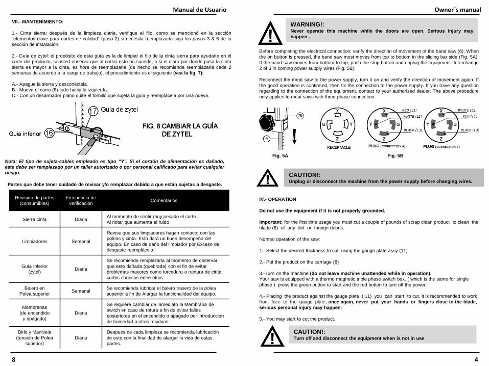
Before completing the electrical connection, verify the direction of movement of the band saw (6). When
the on button is pressed, the band saw must moves from top to bottom in the sliding bar side (Fig. 5A).
If the band saw moves from bottom to top, push the stop button and unplug the equipment. Interchange
2 of 3 in coming power supply wires (Fig. 5B).
Reconnect the meat saw to the power supply, turn it on and verify the direction of movement again. If
the good operation is confirmed, then fix the connection to the power supply. If you have any question
regarding to the connection of the equipment, contact to your authorized dealer. The above procedure
only applies to meat saws with three phase connection.
IV.- OPERATION
Do not use the equipment if it is not properly grounded.
Important: for the first time usage you must cut a couple of pounds of scrap clean product to clean the
blade (6) of any dirt or foreign debris.
Normal operation of the saw:
1.- Select the desired thickness to cut, using the gauge plate assy (11).
2.- Put the product on the carriage (8)
3.-Turn on the machine (do not leave machine unattended while in operation).
Your saw is equipped with a thermo magnetic triple phase switch box, ( which is the same for single
phase ) press the green button to start and the red button to turn off the power.
4.- Placing the product against the gauge plate ( 11) you can start to cut, it is recommended to work
front face to the gauge plate, once again, never put your hands or fingers close to the blade,
serious personal injury may happen.
5.- You may start to cut the product.
WARNING!:Never operate this machine while the doors are open. Serious injury may
happen .
CAUTION!:Turn off and disconnect the equipment when is not in use
VII.- MANTENIMIENTO:
1.- Cinta sierra: después de la limpieza diaria, verifique el filo, como se mencionó en la sección
“elementos clave para cortes de calidad” (paso 2) si necesita reemplazarla siga los pasos 3 & 6 de la
sección de instalación.
2.- Guía de zytel: el propósito de esta guía es la de limpiar el filo de la cinta sierra para ayudarle en el
corte del producto, si usted observa que al cortar esto no sucede, o si el claro por donde pasa la cinta
sierra es mayor a la cinta, es hora de reemplazarla (de hecho se recomienda reemplazarla cada 2
semanas de acuerdo a la carga de trabajo), el procedimiento es el siguiente (vea la fig. 7):
Revisión de partes
(consumibles)
Frecuencia de
verificación Comentarios
Sierra cinta DiariaAl momento de sentir muy pesado el corte.
Al notar que aumenta el ruido
Limpiadores Semanal
Revise que sus limpiadores hagan contacto con las
poleas y cinta. Esto dará un buen desempeño del
equipo. En caso de daño del limpiador por Exceso de
desgaste reemplácelo.
Guía inferior
(zytel)Diaria
Se recomienda remplazarla al momento de observar
que este dañada (quebrada) con el fin de evitar
problemas mayores como torcedura o ruptura de cinta,
cortes chuecos entre otros.
Balero en
Polea superior Semanal
Se recomienda lubricar el balero trasero de la polea
superior a fin de Alargar la funcionalidad del equipo.
Membranas
(de encendido
y apagado)
Diaria
Se requiere cambiar de inmediato la Membrana de
switch en caso de rotura a fin de evitar fallas
posteriores en el encendido o apagado por introducción
de humedad u otros residuos.
Birlo y Manivela
(tensión de Polea
superior)
Diaria
Después de cada limpieza se recomienda lubricación
de este con la finalidad de alargar la vida de estas
partes.
Partes que debe tener cuidado de revisar y/o remplazar debido a que están sujetas a desgaste.
Manual de Usuario
8
Nota: El tipo de sujeta-cables empleado es tipo “Y”. Si el cordón de alimentación es dañado,
este debe ser remplazado por un taller autorizado o por personal calificado para evitar cualquier
riesgo.
A.- Apague la sierra y desconéctela.
B.- Mueva el carro (8) todo hacia la izquierda.
C.- Con un desarmador plano quite el tornillo que sujeta la guía y reemplácela por una nueva.
Fig. 5A Fig. 5B
CAUTION!:Unplug or disconnect the machine from the power supply before changing wires.
Owner´s manual
5
In addition to the mentioned devices, the meat saw comes with
a band saw guard too. It is to prevent any unwanted contact from
the band saw while the equipment is working even if the
equipment is turned off due the band saw is dangerous by
nature.
For adjusting the band saw guard, turn counterclockwise the
superior handle (24) (Fig 6a) for releasing and adjusting the
height enough to cut meat. Turn clockwise the superior handle to
fix again the band guard saw.
If the meat saw is not been used, slide down the band saw
guard until the table assy (5) for covering completely the band
saw.
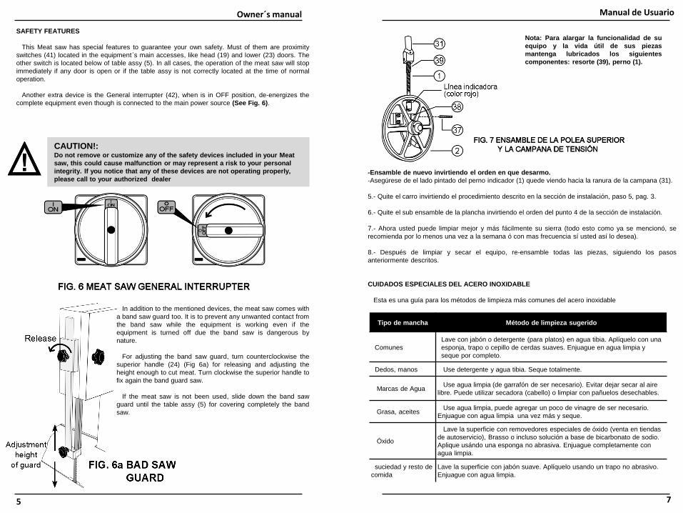
Nota: Para alargar la funcionalidad de su
equipo y la vida útil de sus piezas
mantenga lubricados los siguientes
componentes: resorte (39), perno (1).
Tipo de mancha Método de limpieza sugerido
Comunes
Lave con jabón o detergente (para platos) en agua tibia. Aplíquelo con una
esponja, trapo o cepillo de cerdas suaves. Enjuague en agua limpia y
seque por completo.
Dedos, manos Use detergente y agua tibia. Seque totalmente.
Marcas de AguaUse agua limpia (de garrafón de ser necesario). Evitar dejar secar al aire
libre. Puede utilizar secadora (cabello) o limpiar con pañuelos desechables.
Grasa, aceitesUse agua limpia, puede agregar un poco de vinagre de ser necesario.
Enjuague con agua limpia una vez más y seque.
Óxido
Lave la superficie con removedores especiales de óxido (venta en tiendas
de autoservicio), Brasso o incluso solución a base de bicarbonato de sodio.
Aplique usándo una esponga no abrasiva. Enjuague completamente con
agua limpia.
suciedad y resto de
comida
Lave la superficie con jabón suave. Aplíquelo usando un trapo no abrasivo.
Enjuague con agua limpia.
Manual de Usuario
7
-Ensamble de nuevo invirtiendo el orden en que desarmo.
-Asegúrese de el lado pintado del perno indicador (1) quede viendo hacia la ranura de la campana (31).
5.- Quite el carro invirtiendo el procedimiento descrito en la sección de instalación, paso 5, pag. 3.
6.- Quite el sub ensamble de la plancha invirtiendo el orden del punto 4 de la sección de instalación.
7.- Ahora usted puede limpiar mejor y más fácilmente su sierra (todo esto como ya se mencionó, se
recomienda por lo menos una vez a la semana ó con mas frecuencia sí usted así lo desea).
8.- Después de limpiar y secar el equipo, re-ensamble todas las piezas, siguiendo los pasos
anteriormente descritos.
CUIDADOS ESPECIALES DEL ACERO INOXIDABLE
Esta es una guía para los métodos de limpieza más comunes del acero inoxidable
CAUTION!:Do not remove or customize any of the safety devices included in your Meat
saw, this could cause malfunction or may represent a risk to your personal
integrity. If you notice that any of these devices are not operating properly,
please call to your authorized dealer
SAFETY FEATURES
This Meat saw has special features to guarantee your own safety. Must of them are proximity
switches (41) located in the equipment´s main accesses, like head (19) and lower (23) doors. The
other switch is located below of table assy (5). In all cases, the operation of the meat saw will stop
immediately if any door is open or if the table assy is not correctly located at the time of normal
operation.
Another extra device is the General interrupter (42), when is in OFF position, de-energizes the
complete equipment even though is connected to the main power source (See Fig. 6).
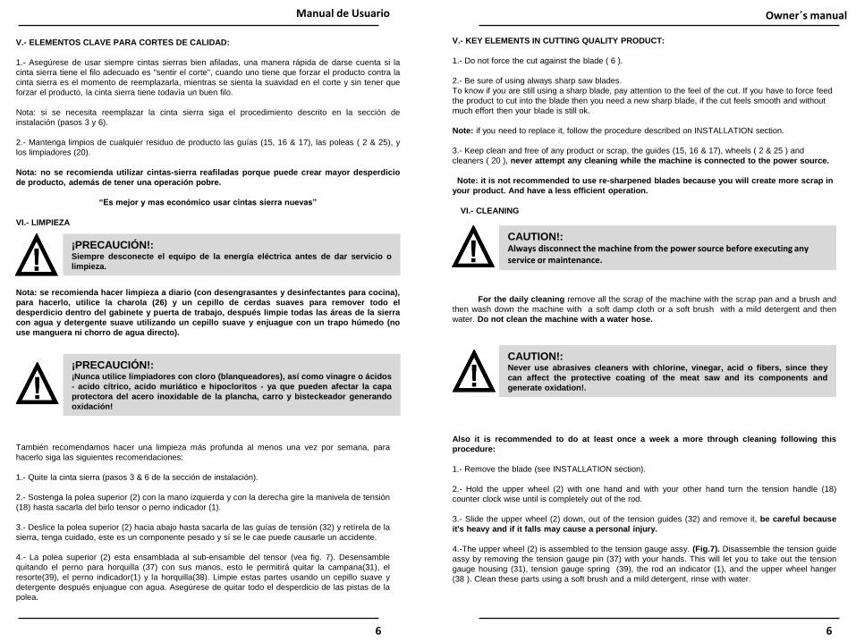
For the daily cleaning remove all the scrap of the machine with the scrap pan and a brush and
then wash down the machine with a soft damp cloth or a soft brush with a mild detergent and then
water. Do not clean the machine with a water hose.
Also it is recommended to do at least once a week a more through cleaning following this
procedure:
1.- Remove the blade (see INSTALLATION section).
2.- Hold the upper wheel (2) with one hand and with your other hand turn the tension handle (18)
counter clock wise until is completely out of the rod.
3.- Slide the upper wheel (2) down, out of the tension guides (32) and remove it, be careful because
it's heavy and if it falls may cause a personal injury.
4.-The upper wheel (2) is assembled to the tension gauge assy. (Fig.7). Disassemble the tension guide
assy by removing the tension gauge pin (37) with your hands. This will let you to take out the tension
gauge housing (31), tension gauge spring (39), the rod an indicator (1), and the upper wheel hanger
(38 ). Clean these parts using a soft brush and a mild detergent, rinse with water.
CAUTION!:Never use abrasives cleaners with chlorine, vinegar, acid o fibers, since they
can affect the protective coating of the meat saw and its components and
generate oxidation!.
CAUTION!:Always disconnect the machine from the power source before executing any service or maintenance.
VI.- CLEANING
Owner´s manual
6
V.- ELEMENTOS CLAVE PARA CORTES DE CALIDAD:
1.- Asegúrese de usar siempre cintas sierras bien afiladas, una manera rápida de darse cuenta si la
cinta sierra tiene el filo adecuado es "sentir el corte", cuando uno tiene que forzar el producto contra la
cinta sierra es el momento de reemplazarla, mientras se sienta la suavidad en el corte y sin tener que
forzar el producto, la cinta sierra tiene todavía un buen filo.
Nota: si se necesita reemplazar la cinta sierra siga el procedimiento descrito en la sección de
instalación (pasos 3 y 6).
2.- Mantenga limpios de cualquier residuo de producto las guías (15, 16 & 17), las poleas ( 2 & 25), y
los limpiadores (20).
Nota: no se recomienda utilizar cintas-sierra reafiladas porque puede crear mayor desperdicio
de producto, además de tener una operación pobre.
“Es mejor y mas económico usar cintas sierra nuevas”
VI.- LIMPIEZA
Nota: se recomienda hacer limpieza a diario (con desengrasantes y desinfectantes para cocina),
para hacerlo, utilice la charola (26) y un cepillo de cerdas suaves para remover todo el
desperdicio dentro del gabinete y puerta de trabajo, después limpie todas las áreas de la sierra
con agua y detergente suave utilizando un cepillo suave y enjuague con un trapo húmedo (no
use manguera ni chorro de agua directo).
También recomendamos hacer una limpieza más profunda al menos una vez por semana, para
hacerlo siga las siguientes recomendaciones:
1.- Quite la cinta sierra (pasos 3 & 6 de la sección de instalación).
2.- Sostenga la polea superior (2) con la mano izquierda y con la derecha gire la manivela de tensión
(18) hasta sacarla del birlo tensor o perno indicador (1).
3.- Deslice la polea superior (2) hacia abajo hasta sacarla de las guías de tensión (32) y retírela de la
sierra, tenga cuidado, este es un componente pesado y sí se le cae puede causarle un accidente.
4.- La polea superior (2) esta ensamblada al sub-ensamble del tensor (vea fig. 7). Desensamble
quitando el perno para horquilla (37) con sus manos, esto le permitirá quitar la campana(31), el
resorte(39), el perno indicador(1) y la horquilla(38). Limpie estas partes usando un cepillo suave y
detergente después enjuague con agua. Asegúrese de quitar todo el desperdicio de las pistas de la
polea.
¡PRECAUCIÓN!:¡Nunca utilice limpiadores con cloro (blanqueadores), así como vinagre o ácidos
- acido cítrico, acido muriático e hipocloritos - ya que pueden afectar la capa
protectora del acero inoxidable de la plancha, carro y bisteckeador generando
oxidación!
¡PRECAUCIÓN!:Siempre desconecte el equipo de la energía eléctrica antes de dar servicio o
limpieza.
Manual de Usuario
6
V.- KEY ELEMENTS IN CUTTING QUALITY PRODUCT:
1.- Do not force the cut against the blade ( 6 ).
2.- Be sure of using always sharp saw blades.
To know if you are still using a sharp blade, pay attention to the feel of the cut. If you have to force feed
the product to cut into the blade then you need a new sharp blade, if the cut feels smooth and without
much effort then your blade is still ok.
Note: if you need to replace it, follow the procedure described on INSTALLATION section.
3.- Keep clean and free of any product or scrap, the guides (15, 16 & 17), wheels ( 2 & 25 ) and
cleaners ( 20 ), never attempt any cleaning while the machine is connected to the power source.
Note: it is not recommended to use re-sharpened blades because you will create more scrap in
your product. And have a less efficient operation.

Assemble again, reversing the disassemble order, taking care that the red color painted side of the rod
and indicator (1) face the hole at the tension gauge housing (31).
5.- Move the carriage (8) to your right until stop, then with your finger, lift the carriage-lock ( 9 ) and slide
again to your right to remove the carriage from its guide ( see fig. 3 ).
6.- Now remove the table assy.
7.- Now you can clean the saw easier. (We recommend to do this at least once a week) or often if you
want it.
8.-.After a very deep cleaning and drying of the machine, assemble back in reverse order following the
steps on INSTALLATION section
STAINLESS STEEL SPECIAL CARE
This is a guideline of cleaning methods for stainless steel.
Requirement Suggested Method
Routine cleaning
of light soiling
Wash with Soap or detergent in warm clean water. Apply with a clean
sponge, soft cloth or soft-fiber brush then rinse in clean water and dry.
Fingerprints Use Detergent. Rinse with warm water. Dry totally
Watermarks
Use clean rinsing water, such as reasonable quality potable (tap) water.
Drying marks may be avoided using an air blower or wiping with clean
disposable wipes.
Grease marksUse clean rinsing water , you could add white vinegar or soft water solution.
Rinse with warm water again and dry.
Rust stains
Wash surface with CLR (calcium, lime & rust remover) type cleaner. Use
not acid and recommended solution. Apply using a soft non-abrasive
sponge. Rinse surface thoroughly with clean soft water after application.
Dirt and debrisWash surface with a mild liquid soap. Apply using a soft, non-abrasive cloth.
Rinse surface thoroughly with clean soft water.
Owner´s manual
7
Note: To guarantee the right operation of
the equipment, keep lubricated the next
elements:
Tension gauge Spring (39)
Rod and indicator (1)
¡PRECAUCIÓN!:Cambiar, modificar o retirar cualquier de los dispositivos de seguridad
incluidos en la sierra de carne, podría representar un mal funcionamiento o
un grave riesgo para la integridad de la persona que opere el equipo.
Si usted observa que cualquiera de estos dispositivos no están operando
adecuadamente, por favor llame a su distribuidor autorizado.
DISPOSITIVOS DE SEGURIDAD
Para garantizar su propia seguridad y la de cualquier persona que opere este equipo, la sierra de
carne contiene dispositivos especiales integrados, la mayoría de ellos son sensores de proximidad
o interlocks (41) ubicados en los principales accesos como la puerta el cabezal (19) y la puerta
inferior (23). El otro sensor está localizado debajo del subensamble de la plancha (5). Para todos
los casos, el funcionamiento de la sierra se detendrá inmediatamente si cualquier puerta es abierta
o la plancha no está correctamente posicionada durante la operación normal.
Otro de los dispositivos extra es el interruptor general (42), que cuando esta en la posición de
OFF, desenergiza el equipo completo a pesar de que éste se encuentre conectado a la
alimentación principal (Ver Fig. 6).
Manual de Usuario
5
Además de los dispositivos anteriores, el equipo cuenta con la
guarda de cinta sierra. La cual le previene de entrar en contacto
con la cinta sierra mientras el equipo se encuentra en
funcionamiento o incluso sí está apagado, ya que por naturaleza la
cinta sierra es peligrosa.
Para ajustar la guarda gire la manija superior (24) (fig. 6a) en
sentido anti horario, ajuste la guarda a una altura suficiente para
poder cortar el producto dejando el resto de la cinta sierra cubierta.
Asegure nuevamente la guarda con ayuda de la manija superior
girándola en sentido contrario.
Al final de la operación deslice la guarda hasta que tope con la
plancha de la sierra para dejar cubierta la cinta sierra mientras no
se esté usando el equipo.
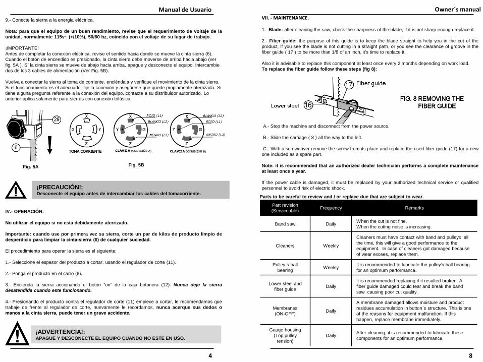
VII. - MAINTENANCE.
1.- Blade: after cleaning the saw, check the sharpness of the blade, if it is not sharp enough replace it.
2.- Fiber guide: the purpose of this guide is to keep the blade straight to help you in the cut of the
product, if you see the blade is not cutting in a straight path, or you see the clearance of groove in the
fiber guide ( 17 ) to be more than 1/8 of an inch, it's time to replace it.
Also it is advisable to replace this component at least once every 2 months depending on work load.
To replace the fiber guide follow these steps (fig 8):
A.- Stop the machine and disconnect from the power source.
B.- Slide the carriage ( 8 ) all the way to the left.
C.- With a screwdriver remove the screw from its place and replace the used fiber guide (17) for a new
one included as a spare part.
Note: it is recommended that an authorized dealer technician performs a complete maintenance
at least once a year.
If the power cable is damaged, it must be replaced by your authorized technical service or qualified
personnel to avoid risk of electric shock.
Part revision
(Serviceable)Frequency Remarks
Band saw DailyWhen the cut is not fine.
When the cuttng noise is increasing.
Cleaners Weekly
Cleaners must have contact with band and pulleys all
the time, this will give a good performance to the
equipment. In case of cleaners got damaged because
of wear excees, replace them.
Pulley´s ball
bearingWeekly
It is recommended to lubricate the pulley’s ball bearing
for an optimum performance.
Lower steel and
fiber guideDaily
It is recommended replacing if it resulted broken. A
fiber guide damaged could tear and break the band
saw causing poor cut quality.
Membranes
(ON-OFF)Daily
A membrane damaged allows moisture and product
residues accumulation in button´s structure. This is one
of the reasons for equipment malfunction. If this
happen, replace membrane immediately.
Gauge housing
(Top pulley
tension)
DailyAfter cleaning, it is recommended to lubricate these
components for an optimum performance.
Parts to be careful to review and / or replace due that are subject to wear.
Owner´s manual
8
9.- Conecte la sierra a la energía eléctrica.
Nota: para que el equipo de un buen rendimiento, revise que el requerimiento de voltaje de la
unidad, normalmente 115v~ (+/10%), 50/60 hz, coincida con el voltaje de su lugar de trabajo.
¡IMPORTANTE!
Antes de completar la conexión eléctrica, revise el sentido hacia donde se mueve la cinta sierra (6).
Cuando el botón de encendido es presionado, la cinta sierra debe moverse de arriba hacia abajo (ver
fig. 5A ). Sí la cinta sierra se mueve de abajo hacia arriba, apague y desconecte el equipo. Intercambie
dos de los 3 cables de alimentación (Ver Fig. 5B).
Vuelva a conectar la sierra al toma de corriente, enciéndala y verifique el movimiento de la cinta sierra.
Si el funcionamiento es el adecuado, fije la conexión y asegúrese que quede propiamente aterrizada. Si
tiene alguna pregunta referente a la conexión del equipo, contacte a su distribuidor autorizado. Lo
anterior aplica solamente para sierras con conexión trifásica.
IV.- OPERACIÓN:
No utilizar el equipo si no esta debidamente aterrizado.
Importante: cuando use por primera vez su sierra, corte un par de kilos de producto limpio de
desperdicio para limpiar la cinta-sierra (6) de cualquier suciedad.
El procedimiento para operar la sierra es el siguiente:
1.- Seleccione el espesor del producto a cortar, usando el regulador de corte (11).
2.- Ponga el producto en el carro (8).
3.- Encienda la sierra accionando el botón “on” de la caja botonera (12). Nunca deje la sierra
desatendida cuando este funcionando.
4.- Presionando el producto contra el regulador de corte (11) empiece a cortar, le recomendamos que
trabaje de frente al regulador de corte, nuevamente le recordamos, nunca acerque sus dedos o
manos a la cinta sierra, puede tener un grave accidente.
¡ADVERTENCIA!:APAGUE Y DESCONECTE EL EQUIPO CUANDO NO ESTE EN USO.
Manual de Usuario
4
Fig. 5A Fig. 5B
¡PRECAUCIÓN!:Desconecte el equipo antes de intercambiar los cables del tomacorriente.

VIII.- EQUIPMENT SPECIFICATION
A) ELECTRICAL SPECIFICATIONS (Depends on your equipment. See ID plate):.
Equipment Voltage Current Frequency Capacity
Meat Saw
115 V~ 21 A 60 Hz 1,1 KW (1,5 HP)
220 V~ 11 A50 OR 60
Hz1,1 KW (1,5 HP)
220 V3~ 8.4 A50 OR 60
Hz2,2 KW (3 HP)
380 V3~ 6.2 A 50 HZ 2.2 kW (3 HP)
B) GENERAL DIMENSIONS.
IX. - ELECTRICAL DIAGRAM:
The electrical diagram for this unit is located inside the cabinet.
WARNING!:The cabinet for this equipment must be opened
by qualified personnel only.
For any problem or doubt related to electric specifications
and connections, please call to your authorized dealer.
Owner´s manual
9
Manual de Usuario
B.-Con cuidado tome el sub-ensamble de la plancha (5), colóquelo sobre los ángulos porta plancha (21)
sobre el gabinete.
C.-Inserte primero un perno en la ranura de los ángulos porta plancha (21) como se muestra en el paso
“a" de la fig. 2, ahora coloque el perno de lado derecho en las otras ranuras, como se muestra en el
paso “b" de la misma figura.
D.- Asegure firmemente ambos pernos (35) en las ranuras de los ángulos porta plancha (21).
E.-Ahora gire el candado (22) firmemente hacia adentro del gabinete para asegurar y mantener la
plancha (5) en su lugar.
5.- Instale el sub-ensamble del carro (8) en la canal (27), siguiendo el proceso descrito :
A.- Tome el carro (8) referenciándose en la imagen mostrada (ver fig. 3).
B.- Inserte el carro asegurándose que los rodamientos entren en la guía.
C.- Mueva el carro totalmente a la izquierda hasta que el candado (9) pase el stopper (34).
Nota: Para quitar el carro levante el candado y estírelo completamente. Usted puede fijar el
carro y evitar que este se mueva usando la manija fijadora para carro (36).
6.- Instalación de la cinta sierra (6):
A.- El primer paso es tomar la cinta sierra en la posición que va a ser colocada, la referencia son los
dientes, la dirección de los mismos deberá de ser hacia abajo, que es la dirección del corte como
se muestra en el detalle "a" de la fig. 4.
B.- Ahora coloque la cinta sierra en las poleas (2 & 25), primero en la superior, luego en la inferior,
colóquela ahora en las guías (15, 16 & 17) y entre los limpiadores (20).
C.- Gire la manivela del tensión (18), a favor de las manecillas del reloj, hasta que en la mirilla (1) del
ensamble de la campana (31) se observe la línea roja que indica la tensión adecuada de la cinta sierra.
D.- Gire la polea superior (2) a favor de las manecillas del reloj, 2 ó 3 revoluciones con su mano “haga
esto con mucho cuidado”, para verificar que todo esta correcto.
E.- Asegúrese que la cinta sierra esté bien alineada (separación de 1/32” entre ceja de polea y cinta
sierra).
Nota: no apriete en exceso la manivela del tensor, pues esto causara sobrecalentamiento
7.- Cierre todas las puertas.
8.- Seleccione el lugar de trabajo y asegúrese que la superficie donde se coloque el equipo esta limpia
y nivelada. Use las patas de nivelación (28) para nivelar perfectamente la sierra.
3

Owner´s manual
X.- ELECTROMAGNETIC BRAKE (SOME MODELS ONLY):
Your meat saw may be equipped with an
electromagnetic brake (see Fig. A1). If so,
please refer to this information for proper
operation and maintenance.
The brake motor is installed on the
transmission system of the meat saw. It stops
the motor and the saw band in less than 3
seconds.
A. OPERATION
The band saw stays locked when the meat
saw is off. When the meat saw is turned on the
brake releases the transmission pulley and the
band saw can rotate.
If you turn the meat saw off the brake will lock
the transmission pulley making that the motor
stops.
B. ELECTRICAL CONNECTION
The brake is connected to the control box through a rectifier. (See Fig A2).
C. STEPS FOR UNINSTALLING
1. Unplug the meat saw. Locate the brake on the transmission system.
2. Loosen the screws from the upper support.
3. Pull the brake and remove it from de shaft pulley.
D. STEPS FOR INSTALLING
1. Verify the concentricity between the friction plate and the rear plate (See Fig A3) before
assembling the brake. For this operation refer to “Centering the Friction Plate” section .
2. If it is necessary adjust the Air Gap, refer to “Air gap adjustment” Section.
3. Mount the brake on the shaft pulley until all edges are aligned with the edge of the pulley.
4. Screws the upper support hinge and the base of the brake to the cabinet Support.
E. CENTERING THE FRICTION PLATE
The friction plate is aligned from factory, but in some cases, due to transportation or if the equipment
is drastically moved, the friction plate could loose this alignment. If this happen, uninstall the brake and
follow these steps to center it again.
10
Manual de Usuario
II.- DESEMPACADO:
Al desempacar el equipo, asegúrese que estén completos los siguientes componentes* para su
ensamble posterior:
1 Sierra cinta -refacción (6) 1 Empujador de último corte (40 - algunos modelos)
1 Guia de zytel - refacción (17) 4 Regatones (33 - solo algunos modelos)
1 Charola recolectora (26)
1 Subensamble del carro (8)
1 Subensamble de la plancha (5)
Nota: Ver los números de referencia en “Diagrama de componentes de la sierra” (Pág central) .
III.- INSTALACIÓN:
Antes de conectar la sierra a la energía eléctrica, siga estas sencillas instrucciones de ensamble.
(Nunca lleve a cabo estos pasos con la sierra conectada a la energía eléctrica).
1.- Coloque la sierra en un lugar limpio, seco y nivelado [para nivelar la sierra use la pata de nivelación
(28), asegúrese que la sierra quede cerca de la energía eléctrica.
2.- Asegúrese de que las poleas (2 & 25), y la cinta sierra (6), se muevan libres de cualquier objeto.
3.- Es posible instalar el sub-ensamble de la plancha (5) directamente en la sierra, pero para evitar
daños en la cinta, le sugerimos retirarla mientras se ensambla la plancha siguiendo este procedimiento:
A.- Abra la puerta de el cabezal (19), y la puerta inferior derecha (23).
B.- Gire la guía de zytel (17), (ver fig.1).
C.- Gire la manivela del tensión (18) en contra de las manecillas del reloj hasta que la cinta (6) se afloje.
D.- Saque la cinta-sierra de las poleas (2 & 25), guías (15, 16 & 17) y limpiadores (20)
4.- Ya puede Instalar el sub-ensamble de la plancha (5) siguiendo este procedimiento (vea fig. 2):
A.-Asegúrese que la puerta del cabezal (19) y la puerta inferior derecha (23) estén abiertas.
2

INSTRUCCIONES DE OPERACIÓN
CONTENIDO: PÁG.
I. INTRODUCCIÓN 1
II. DESEMPACADO 2
III. INSTALACION 2
IV. OPERACION 4
V. ELEMENTOS CLAVE PARA CORTES CON CALIDAD 5
VI. LIMPIEZA 5
VII. MANTENIMIENTO 7
VIII. ESPECIFICACIONES ELÉCTRICAS 8
IX. DIAGRAMA ELÈCTRICO 9
X. FRENO ELECTROMAGNÉTICO (ALGUNOS MODELOS) 10
¡ADVERTENCIA!:Esta maquina esta diseñada para cortar carne, hueso y algunos otros productos
alimenticios, y por su naturaleza es peligrosa si no se utiliza con conocimiento
y precaución.
I.- INTRODUCCIÓN:
Felicidades! Usted a adquirido una sierra para carne la cual esta fabricada con los mejores
materiales y mano de obra, lo que le asegurara una larga vida y un excelente servicio.
Para garantizar el óptimo funcionamiento de su equipo, se deberán de tomar en cuenta las
precauciones y recomendaciones incluidas en este manual.
¡IMPORTANTE!: “Es de vital importancia que Usted o cualquier otra persona que se relacione con el
equipo, lea detenidamente este manual.”
Este equipo debe ser conectado a una conexión con protección térmica. Recuerde que su equipo
debe de estar aterrizado para evitar algún accidente.
Manual de Usuario
1
ESPAÑOL
Esta unidad no se puede usar por personas (incluidos niños) con
discapacidades físicas, sensoriales o mentales, o la falta de
experiencia y conocimiento, a menos que hayan recibido supervisión o
instrucción previamente. Los niños, aún bajo supervisión, no deben
jugar con el equipo.
Nunca de servicio, limpieza o mantenimiento a esta unidad mientras
esté conectada a la energía eléctrica.
¡Peligro! No utilice directamente sus manos o cualquier otra
extremidad de su cuerpo para alimentar la sierra con el producto a
cortar. De ser así, mantenga una distancia mínima de 10 cms con la
hoja.
Apague el equipo cuando no este en uso .
11
1. Release the brake (Fig A5) turning clockwise the screw in the lever of brake’s ring.
2. After this, the friction plate (cylinder shown in Fig A3 at back side of brake), will freely move.
3. Use your hand to center the cylinder into the circumference.
4. Turn screw counter-clockwise to lock the friction plate and carefully install the brake again.
D. AIR GAP ADJUSTMENT
After a long time usage, the brake will need to be adjusted. Using a 5/32” allen wrench (included),
turn the adjustment screws (see Fig A4) counterclockwise a quarter turn.
Turn the meat saw on and then turn it off to verify the braking time (lees than 3 seconds). Turn a quarter
turn more the screws if it is necessary.
E. MAINTENANCE
If the equipment requires a band saw
adjustment, you will need to release the pulley. Use
a 5/32” allen wrench (included) and turn the screw
(see Fig A5) clockwise a whole turn. Complete
service and screw back to previous position to lock
the pulley again.
WARNING!:Before a service and maintenance you must unplug the meat saw from the
power supply.
If you have any doubt regarding the brake operation or installation, please contact your authorized
dealer.
IMPORTANT!:The gap must be the same along the
brake´s circumference. A correct adjust
will avoid overheating.
Owner´s manual

Manual de Usuario
Apéndice
DIAGRAMA DE COMPONENTES DE LA SIERRA (VER PAGINAS CENTRALES)
Owner´s manual
Appendix
MEAT SAW DIAGRAM FOR COMPONENTS (SEE CENTRAL PAGES)
Owner´s manual
Appendix
Manual de Usuario
Apéndice
MEAT SAW DIAGRAM FOR COMPONENTS
DIAGRAMA DE COMPONENTES DE LA SIERRA