Embed Size (px)
Citation preview
OWNER’S MANUAL Thank-you and congratulations for purchasing a high quality Airmac air compressor set. It has been designed and manufactured to provide many years of safe and reliable service if installed, operated and maintained in accordance with these instructions. Please read and understand this manual before operating the compressor. Failure to do so could result in death, severe injury and/or substantial property damage. This manual should be considered a permanent part of the compressor and should remain with it if resold.
72 Platinum Street, Crestmead, QLD 4132, Australia
Phone: (07) 3803 4100 Fax: (07) 3803 1255 Email: [email protected] Web: www.glencomfg.com.au
Airmac Owner’s Manual
August 2006 © Glenco Manufacturing Pty Ltd Page 2 of 44
SAFETY Compressed air can contain carbon monoxide, hydrocarbons and/or other poisonous contaminants that can cause death or serious injury. The air compressor is not designed, intended or approved for breathing air. Do not use compressed air for breathing air applications without proper treatment. Do not use the compressor for any gas other than air. High voltage electricity can cause death or serious injury. All electrical installation or repair work must be carried out by a licensed electrician. The compressor must be connected to a properly grounded circuit of adequate capacity. Disconnect power supply before servicing. Do not operate the compressor in wet conditions. Store indoors. Petrol and diesel fuels are flammable and poisonous and can cause death or serious injury. Do not smoke or allow flames or sparks close to the engine. Exhaust gas contains poisonous carbon monoxide that can cause death or serious injury. Ensure adequate ventilation and do not operate the engine in a closed garage or confined space. The 12 Volt battery gives off explosive gases and its electrolyte contains corrosive acid, either of which can cause death or serious injury. Keep sparks, flames and cigarettes away from the battery and provide adequate ventilation when charging. Do not allow the electrolyte to contact body or clothing. Read and understand the separate Owner’s Manual for the petrol or diesel engine before operating the compressor. Moving parts can cause serious injury. Keep clear of the compressor during operation. Do not operate with the drive guard removed. The compressor may start automatically. Disconnect the power supply or switch-off engine before servicing. Hot surfaces can cause serious injury. Do not touch metal surface of any compressor component (including piping and tank) during or shortly after operation. Allow to cool before servicing. Do not stand on the compressor or use it as a handhold. Keep children, pets and unauthorized persons away from the compressor at all times. High pressure air can cause death or serious injury. Do not bypass, modify or remove the safety valve. Do not operate the compressor with a faulty safety valve or pressure gauge. Do not direct the air stream at body. High pressure air can stir up dust and debris that may be harmful. Release air slowly when draining condensate water or depressurizing the compressor. Do not connect the compressor to air handling parts that cannot withstand the compressor’s maximum design pressure (refer to tank nameplate).
Airmac Owner’s Manual
August 2006 © Glenco Manufacturing Pty Ltd Page 3 of 44
Rusted, cracked or damaged air receiver tanks can explode and cause death or serious injury and must be replaced. Drain tank daily or after each use through valve located at bottom of tank. Release compressed air from the tank before servicing. Do not weld, drill or otherwise modify the air receiver tank. Wear personal protection equipment such as safety glasses, ear muffs and gloves when operating the compressor or using compressed air. Wear a face mask or respirator when spraying, blowing down or otherwise creating airborne mists or dust. Do not spray flammable liquids in a confined area. Do not smoke while spraying and do not spray where sparks, flames or other ignition sources (including the compressor) are present. Do not direct paint or other sprayed material at the compressor. Locate compressor as far away from the spraying area as possible to minimize overspray accumulating on the compressor and/or clogging its air filter(s). Motors, electrical equipment and controls can cause electrical arcs that may ignite a flammable gas or vapour. Do not operate or repair the compressor in or near a flammable gas or vapour. Do not store flammable liquids or gases in the vicinity of the compressor. Before attempting to install, maintain, repair, store or transport the compressor, switch off the unit, tag and lock out the power supply or disconnect the engine spark plug, and carefully release all air pressure from the receiver tank, air hoses and/or piping. Do not permit anyone to operate the compressor without proper instruction.
Airmac Owner’s Manual
August 2006 © Glenco Manufacturing Pty Ltd Page 4 of 44
INTRODUCTION This Owner’s Manual is intended to comply with all Australian Occupational or Workplace Health and Safety Regulations regarding the manufacturer’s provision of information to the owner or purchaser of work plant. The information is correct at the date of publication. Due to Glenco Manufacturing Pty Ltd’s policy of continued product development, some features and specifications of your new air compressor may vary slightly from those shown herein. If after reading this manual you still have any questions or concerns about your compressor, please contact your local authorized Airmac dealer or Glenco Manufacturing Pty Ltd. Previous purchasers of Airmac and Binford compressors may also rely on this manual as a general guide for their units.

Airmac Owner’s Manual
August 2006 © Glenco Manufacturing Pty Ltd Page 5 of 44
PRODUCT FAMILIARIZATION Typical 240 Volt Single Pump Air Compressor
NO. COMPONENT NO. COMPONENT
1 Compressor Pump 12 Wheel Mounting Bracket
2 Air Filter 13 Handle
3 Crankcase Breather 14 Wheel
4 Oil Fill Cap 15 Non-Return Valve
5 Oil Drain Plug 16 Unloading Line
6 Oil Level Sight Glass 17 Safety Valve
7 Compressor Pump Nameplate 18 Drain Valve
8 Electric Motor 19 Discharge Outlet
9 Air Receiver Tank 20 Pressure Gauge
10 Air Receiver Tank Nameplate 21 Pressure Switch
11 Drive Guard
Airmac Owner’s Manual
August 2006 © Glenco Manufacturing Pty Ltd Page 6 of 44
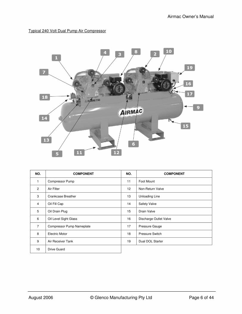
Typical 240 Volt Dual Pump Air Compressor
NO. COMPONENT NO. COMPONENT
1 Compressor Pump 11 Foot Mount
2 Air Filter 12 Non-Return Valve
3 Crankcase Breather 13 Unloading Line
4 Oil Fill Cap 14 Safety Valve
5 Oil Drain Plug 15 Drain Valve
6 Oil Level Sight Glass 16 Discharge Outlet Valve
7 Compressor Pump Nameplate 17 Pressure Gauge
8 Electric Motor 18 Pressure Switch
9 Air Receiver Tank 19 Dual DOL Starter
10 Drive Guard
Airmac Owner’s Manual
August 2006 © Glenco Manufacturing Pty Ltd Page 7 of 44
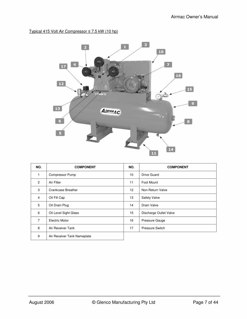
Typical 415 Volt Air Compressor ≤ 7.5 kW (10 hp)
NO. COMPONENT NO. COMPONENT
1 Compressor Pump 10 Drive Guard
2 Air Filter 11 Foot Mount
3 Crankcase Breather 12 Non-Return Valve
4 Oil Fill Cap 13 Safety Valve
5 Oil Drain Plug 14 Drain Valve
6 Oil Level Sight Glass 15 Discharge Outlet Valve
7 Electric Motor 16 Pressure Gauge
8 Air Receiver Tank 17 Pressure Switch
9 Air Receiver Tank Nameplate

Airmac Owner’s Manual
August 2006 © Glenco Manufacturing Pty Ltd Page 8 of 44
Typical 415 Volt Air Compressor ≥ 11 kW (15 hp)
NO. COMPONENT NO. COMPONENT
1 Compressor Pump 11 Non-Return Valve
2 Air Filter 12 Unloading Line
3 Crankcase Breather 13 Safety Valve
4 Oil Fill Cap 14 Drain Valve
5 Oil Drain Plug 15 Discharge Outlet Valve
6 Oil Level Sight Glass 16 Pressure Gauge
7 Electric Motor 17 Pressure Switch
8 Air Receiver Tank 18 Star-Delta Starter
9 Drive Guard 19 Solenoid Valve
10 Foot Mount

Airmac Owner’s Manual
August 2006 © Glenco Manufacturing Pty Ltd Page 9 of 44
Typical Petrol Air Compressor
NO. COMPONENT NO. COMPONENT
1 Compressor Pump 12 Handle
2 Air Filter 13 Wheel
3 Crankcase Breather 14 Non-Return Valve
4 Oil Fill Cap 15 Easy-Start Valve
5 Oil Drain Plug 16 Unloading Line
6 Oil Level Sight Glass 17 Safety Valve
7 Petrol Engine 18 Drain Valve
8 Air Receiver Tank 19 Discharge Outlet
9 Air Receiver Tank Nameplate 20 Pressure Gauge
10 Drive Guard 21 Pilot Valve
11 Wheel Mounting Bracket

Airmac Owner’s Manual
August 2006 © Glenco Manufacturing Pty Ltd Page 10 of 44
Typical Diesel Air Compressor
NO. COMPONENT NO. COMPONENT
1 Compressor Pump 11 Foot Mount
2 Air Filter 12 Vibration Isolator
3 Crankcase Breather 13 Non-Return Valve
4 Oil Fill Cap 14 Easy-Start Valve
5 Oil Drain Plug 15 Unloading Line
6 Oil Level Sight Glass 16 Safety Valve
7 Compressor Pump Nameplate 17 Drain Valve
8 Diesel Engine 18 Discharge Outlet Valve
9 Air Receiver Tank 19 Pressure Gauge
10 Drive Guard 20 Pilot Valve
Airmac Owner’s Manual
August 2006 © Glenco Manufacturing Pty Ltd Page 11 of 44
APPLICATION AND FUNCTION Your Airmac air compressor is a single stage, oil lubricated, and air cooled reciprocating type. It is typically supplied as a compact, self contained, air receiver tank mounted unit that is automatically regulated and driven by an electric motor or internal combustion engine. The compressor is intended to provide compressed air in a multitude of applications, for example, to power pneumatic tools, operate air dusters and spray guns, inflate tyres, and supply air for pneumatic valves and actuators. It is commonly used as the primary source of compressed air for home garages, workshops, service stations, tyre shops, factories, farms, mobile service vehicles, and so on. Supplementary duties can include furnishing compressed air at an isolated location not serviced by the regular shop air system, and standby service when larger compressors are shut down. Air discharged from an oil lubricated compressor typically contains small amounts of oil, water and particulates amongst other contaminants. Virtually all applications require treatment of the compressor’s output air to make it suitable for the end use. Air quality treatments such as filtration and drying are the most common requirements together with pressure regulation. The use of compressed air lubricators to protect pneumatic tools is also commonplace nowadays. Failing to install appropriate compressed air treatment equipment will likely result in damage to pneumatic machinery or spray painted finishes. Where installed, compressed air filtration and/or drying equipment should be located downstream from the air receiver tank and ahead of any pressure regulator. Lubricators, on the other hand, should be installed as the last stage of treatment and located behind or downstream from any pressure regulator. Please contact your Airmac dealer for specialist advice about compressed air treatment products. The basic principle of the compressor’s operation is as follows:
• On the downward suction stroke of the compressor pump piston, air at atmospheric pressure enters the cylinder through the inlet air filter and the inlet valve located in the cylinder head.
• On the upward compression stroke, the piston compresses the air to the final discharge pressure and forces it out through the outlet valve in the cylinder head, past the non-return valve and then into the air receiver tank.
The requisite power to drive the compressor pump is provided by the prime mover, i.e. electric motor, petrol engine or diesel engine, through a V-belt transmission.
Airmac Owner’s Manual
August 2006 © Glenco Manufacturing Pty Ltd Page 12 of 44
On electric models, the pressure switch turns on the motor when the air receiver tank is at or below the minimum “cut-in” pressure. The compressor then operates continuously until the tank pressure reaches the maximum “cut-out” level whereupon the pressure switch turns off the motor. Air can then be heard leaking out from underneath the pressure switch for a short time while the unloader valve releases air pressure trapped in the discharge line between the compressor pump and the non-return valve. This allows the compressor to re-start without being under load. The pressure switch is factory preset with cut-in and cut-out pressures of approximately 650 kPa (94 psi) and 870 kPa (126 psi), respectively. This range is ideal for the vast majority of compressed air applications supplied by an electric air compressor. Most pneumatic tools are designed for a supply pressure of only 620 kPa (90 psi). Unless absolutely necessary for a special application, compressor operation at higher pressures is not recommended because it increases electricity consumption and compressor pump wear and tear. On engine driven models, the pilot valve regulates the operation of the compressor pump to maintain the air receiver tank pressure between the preset cut-in and cut-out levels. Rather than turn off the engine when the cut-out pressure is reached, which would necessitate physically re-starting the engine if more compressed air is required, the pilot valve actuates the head unloader in each cylinder head to keep the inlet valve open. Air can be felt pulsing in and out of the inlet air filter whenever the compressor pump is in this “unloading” mode. When the pressure drops to the cut-in value, the pilot valve deactivates the head unloader in each cylinder whereupon the compressor enters into “pumping” mode. An added feature to reduce fuel consumption, noise emission and wear and tear is the automatic throttle control system whereby engine speed is reduced to idle whenever the compressor is in unloading mode and subsequently increased to maximum revolutions when the compressor switches to pumping mode. The pilot valve is factory preset with cut-in and cut-out pressures of approximately 765 kPa (111 psi) and 965 kPa (140 psi), respectively. This is the optimum range for most applications using an engine driven air compressor. If the pressure switch or pilot valve does not shut off the compressor pump discharge at the cut-off pressure setting, the safety valve will protect the air receiver tank against over pressurizing by automatically releasing air when the pressure exceeds a preset value. Airmac air receiver tanks are designed and manufactured to satisfy the requirements of Australian Standard AS 1210 and all Australian Occupational or Workplace Health and Safety Regulations. A copy of the Manufacturer’s Data Report (as per AS 4458) is available from Glenco Manufacturing Pty Ltd upon request.
Airmac Owner’s Manual
August 2006 © Glenco Manufacturing Pty Ltd Page 13 of 44
The non-return valve is a one-way valve that allows air to enter the tank from the compressor pump, but prevents the reverse of this flow. The drive guard covers the V-belt(s), engine or motor pulley, and the compressor pump pulley. It is a critical safety device. A drain valve is fitted to the bottom of the air receiver tank to permit the release of water condensate that would otherwise corrode the tank and damage pneumatic devices. The pressure within the air receiver tank is indicated on the pressure gauge.

Airmac Owner’s Manual
August 2006 © Glenco Manufacturing Pty Ltd Page 14 of 44
RECEIPT AND INSPECTION Ensure that adequate lifting equipment is available for unloading and moving the air compressor to the installation site. Lifting equipment, slings, etc. must be properly rated for the weight of the compressor. Lift the compressor from the delivery vehicle by the shipping pallet only. Do not use the electric motor lifting eyebolt to lift the entire compressor. The motor lifting eyebolt is only to be used for removing the motor from the compressor unit. Do not work or walk under the compressor while it is suspended in the air. Inspect the compressor upon receipt for any shipping damage or missing parts. If any problems are apparent, make an appropriate note on the delivery receipt before signing and then contact your Airmac dealer immediately. Do not operate unit if damaged during shipping, handling or use. Read the compressor model label to verify it is the model ordered. For electric compressors, check the motor nameplate to verify that it is compatible with the available electricity supply. Make sure that electrical enclosures and components are appropriate for the installation environment.
Airmac Owner’s Manual
August 2006 © Glenco Manufacturing Pty Ltd Page 15 of 44
INSTALLATION Handling Remove the air compressor from its shipping carton and pallet before mounting. Do not use the timber shipping pallet for mounting the compressor. Portable wheel-mounted compressors should only be lifted manually as a last resort and always as a joint lift by at least two persons. Avoid injury and do not attempt to lift a compressor by yourself. Use a mechanical lifting aid, such as a forklift or crane, whenever possible in conjunction with two rope or web slings wrapped under the air receiver tank. Stationary foot-mounted compressors should only be lifted with a mechanical aid. The foot mounts are designed for ease of handling with a forklift in preference to lifting with slings as described above. Compressors have a high centre of gravity due to the elevated position of the compressor pump and engine/motor, which are relatively heavy compared with the air receiver tank. Take care when attaching slings to ensure that the compressor does not tip over. Also, check that the slings do not damage any components especially including the piping, wiring, pressure switch or pilot valve, safety valve, and the pressure gauge. Electric Air Compressors Select a clean, dry and well lit area most preferably indoors with plenty of space for proper ventilation, cooling air flow and accessibility. Locate the compressor at least 300 mm (1 ft) from walls for ventilation or preferably no less than 600 mm (2 ft) to allow for maintenance access. Ensure that the power supply is clearly identified and accessible. Always provide sunshade and shelter from moisture if the compressor has to be located outdoors. Portable wheel mounted type: Assemble the supplied axles and plastic or rubber wheels onto the compressor using one nut and washer per axle/wheel. Apply a small amount of lubricant to the axle/wheel rubbing surfaces. Tighten the axle nuts to 55 Nm (40 lbf-ft). Place the compressor on a firm, level surface that is strong enough to support its weight. Use wheel chocks to prevent movement of the compressor during operation and possible straining of the electrical supply cord or air hose. Do not place on an incline during use as this will interfere with the compressor pump’s splash lubrication system. Stationary skid mounted type: Bolt the compressor to a firm, level foundation such as a concrete floor that is strong enough to support its weight. Do not bolt uneven feet tightly to the foundation as this will cause excessive stress on the air receiver tank. Use metal
Airmac Owner’s Manual
August 2006 © Glenco Manufacturing Pty Ltd Page 16 of 44
shims to pack under any “short” feet, if necessary. The use of flexible vibration isolators underneath the mounting feet is highly recommended and will reduce noise emissions. Portable type compressors may alternatively be installed for stationary duty by bolting down through the holes in the bottom of the wheel mounting brackets. The wheels and axles should not be fitted in such cases. Petrol and Diesel Air Compressors Keep the engine at least 1 metre (3 ft) away from building walls and other equipment to prevent a fire hazard and ensure that the exhaust does not blow onto any surface. An exhaust deflector is supplied with the compressor for use, if necessary. Install the compressor in a location with plenty of space for proper ventilation, cooling air flow and accessibility. Do not install or operate the compressor in a confined area. Provide sunshade and shelter from moisture wherever possible. Portable wheel mounted type: Assemble the supplied axles and rubber wheels onto the compressor using one nut and washer per axle/wheel. Apply a small amount of lubricant to the axle/wheel rubbing surfaces. Tighten the axle nuts to 55 Nm (40 lbf-ft). Use only the supplied rubber wheels or equivalent vibration isolators. Place the compressor on a firm, level surface that is strong enough to support its weight. Use wheel chocks to prevent movement of the compressor during operation and possible straining of the air hose. Do not place on an incline during use as this will interfere with the compressor pump’s splash lubrication system. Stationary skid mounted type: Bolt the compressor to a firm, level foundation that is strong enough to support its weight such as a concrete floor or alternatively secure it to a vehicle chassis/tray for mobile applications. Flexible vibration isolators must be used between the compressor and mounting surface. Do not bolt uneven feet tightly to the foundation as this will cause excessive stress on the air receiver tank. Use metal shims to pack under any “short” feet, if necessary. A vehicle or trailer-mounted compressor must only be operated when in a stationary, horizontal position. Portable type compressors may alternatively be installed for stationary duty by bolting down through the holes in the bottom of the wheel mounting brackets. Flexible vibration isolators must be used. The wheels and axles should not be fitted in such cases. Fill the fuel tank with petrol or diesel as appropriate and check the engine oil level and refill if necessary in accordance with the engine manufacturer’s instructions. Ambient Temperature The air compressor is designed for operation in ambient temperatures of between 0°C (32°F) and 40°C (104°F). Noise Considerations

Airmac Owner’s Manual
August 2006 © Glenco Manufacturing Pty Ltd Page 17 of 44
Check the State Workplace Health and Safety Regulations and/or Local Council Regulations regarding acceptable noise levels. To reduce excessive noise, use vibration isolators, fit intake silencers, install remote air inlets, relocate the compressor, or construct an enclosure or baffle walls. Discharge and Condensate Piping All piping, fittings, air receiver tanks, and so on connected to the compressor discharge must be certified safe for the unit’s discharge pressure and temperature. Do not use PVC plastic in the compressed air discharge line. Use pipe thread sealant on all threads and assemble joints tightly to prevent air leaks and energy wastage. Mainline piping used to convey air throughout a system should be sized to accommodate the maximum flow rate of the compressor (also referred to as it’s free air delivery) in accordance with Table 1. Branch piping should be sized in a similar manner, but the design flow rate should instead be based on the total air consumption of the tools or appliances running off that branch. To allow for vibration and to prevent piping stresses being transmitted to the compressor, the connection between the unit’s discharge valve and the mainline piping system should be made using a flexible air hose or coupling.
TABLE 1
RECOMMENDED PIPE SIZES FOR COMPRESSED AIR LINES
Length of Pipeline (metres)
Flow (L/m) 7.5 15 22.5 30 45 60 75 90
142 1/2” 1/2” 1/2” 1/2” 3/4” 3/4” 3/4” 3/4”
283 1/2” 1/2” 1/2” 3/4” 3/4” 3/4” 3/4” 3/4”
425 1/2” 3/4” 3/4” 3/4” 3/4” 3/4” 3/4” 3/4”
566 3/4” 3/4” 3/4” 3/4” 3/4” 3/4” 3/4” 3/4”
708 3/4” 3/4” 3/4” 3/4” 3/4” 1” 1” 1”
849 3/4” 3/4” 3/4” 3/4” 1” 1” 1” 1”
991 3/4” 3/4” 1” 1” 1” 1” 1” 1”
1,132 3/4” 1” 1” 1” 1” 1” 1” 1”
1,670 1” 1” 1” 1” 1” 1” 1” 1”
2,236 1” 1” 1” 1” 1-1/4” 1-1/4” 1-1/4” 1-1/4”
2,830 1-1/4” 1-1/4” 1-1/4” 1-1/4” 1-1/2” 1-1/2” 1-1/2” 1-1/2”
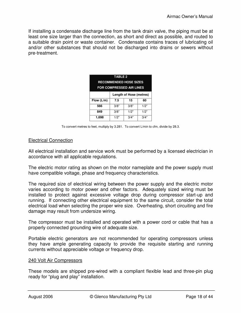
Air hose should be sized in accordance with Table 2, and again with consideration as to whether the hose is a distribution line or a branch line.
Airmac Owner’s Manual
August 2006 © Glenco Manufacturing Pty Ltd Page 18 of 44
If installing a condensate discharge line from the tank drain valve, the piping must be at least one size larger than the connection, as short and direct as possible, and routed to a suitable drain point or waste container. Condensate contains traces of lubricating oil and/or other substances that should not be discharged into drains or sewers without pre-treatment.
TABLE 2
RECOMMENDED HOSE SIZES
FOR COMPRESSED AIR LINES
Length of Hose (metres)
Flow (L/m) 7.5 15 60
566 3/8” 3/8” 1/2”
849 3/8” 1/2” 1/2”
1,698 1/2” 3/4” 3/4”
To convert metres to feet, multiply by 3.281. To convert L/min to cfm, divide by 28.3.
Electrical Connection All electrical installation and service work must be performed by a licensed electrician in accordance with all applicable regulations. The electric motor rating as shown on the motor nameplate and the power supply must have compatible voltage, phase and frequency characteristics. The required size of electrical wiring between the power supply and the electric motor varies according to motor power and other factors. Adequately sized wiring must be installed to protect against excessive voltage drop during compressor start-up and running. If connecting other electrical equipment to the same circuit, consider the total electrical load when selecting the proper wire size. Overheating, short circuiting and fire damage may result from undersize wiring. The compressor must be installed and operated with a power cord or cable that has a properly connected grounding wire of adequate size. Portable electric generators are not recommended for operating compressors unless they have ample generating capacity to provide the requisite starting and running currents without appreciable voltage or frequency drop. 240 Volt Air Compressors These models are shipped pre-wired with a compliant flexible lead and three-pin plug ready for “plug and play” installation.
Airmac Owner’s Manual
August 2006 © Glenco Manufacturing Pty Ltd Page 19 of 44
The compressor’s electrical supply lead should be plugged directly into a suitable power point. Avoid using extension leads because they can damage the electric motor due to under-voltage supply. This is the most common cause of compressor failure and is not covered by warranty. Always use additional air hose instead of an electrical extension lead. Compressors fitted with a standard three-pin 10 Amp electrical plug (on which all three pins have the same cross-section) can be connected to a standard 10 Amp socket provided that there are no other electrical appliances connected to the same branch circuit. They can also be connected to a heavy duty 15 Amp socket. Compressors fitted with a heavy duty three-pin 15 Amp plug (on which the earth pin is noticeably larger in cross-section than the other two pins) must only be connected to a heavy duty 15 Amp socket. No other electrical appliances should be connected to the same branch circuit. Under no circumstances should the 15 Amp plug be modified to fit into a 10 Amp socket. This is a dangerous practice and will void warranty on the motor. Compressors fitted with dual motors must only be connected to two separate 15 Amp sockets. No other electrical appliances should be connected to either of these branch circuits. The direction of motor rotation has been correctly preset at the factory during manufacture. If fitting a replacement motor, check that its direction of rotation is anti-clockwise when viewed looking onto the motor output shaft or compressor pump pulley. Each 240 Volt motor is fitted with its own manual reset thermal overload protection device. 415 Volt Air Compressors These models are shipped with a pre-wired four-core flexible lead that must be either terminated in a suitable four-pin plug or hard-wired for connection to a dedicated electrical supply of adequate capacity fitted with a circuit breaker or fused disconnect switch. This work must be carried out by a licensed electrician. The direction of motor rotation must be checked and properly adjusted during electrical installation. For correct compressor operation, the motor rotation must be anti-clockwise when viewed looking onto the motor output shaft. This can be readily verified by looking at the compressor pump pulley through the drive guard. When viewed looking onto the pulley side (i.e. looking onto the “rear” of the drive guard), the compressor pump’s direction of rotation must be anti-clockwise. Each 415 Volt compressor is fitted with an adjustable automatic reset thermal overload relay that is either built into the pressure switch or the star-delta starter.
Airmac Owner’s Manual
August 2006 © Glenco Manufacturing Pty Ltd Page 20 of 44
12 Volt Electric Start Petrol and Diesel Air Compressors Electric start petrol and diesel air compressors must be connected to a 12 Volt battery in order to utilize this feature. Use a 12 Volt battery of sufficient amp-hour and cold cranking amp capacity in accordance with the engine manufacturer’s instructions. Connect the battery positive (+) cable to the starter solenoid terminal. Connect the battery negative (−) cable to an engine mounting bolt, frame bolt, or other good engine ground connection. Connect the battery positive (+) cable to the battery positive (+) terminal. Connect the battery negative (−) cable to the battery negative (−) terminal. Take care not to connect the battery in reverse polarity as this may damage the battery charging system. Check the battery cable connections to be sure the cables are tight and free of corrosion. Remove any corrosion, and coat the terminals and cable ends with corrosion-preventing grease. Remove the cable from the battery negative (−) terminal before carrying out any maintenance or repairs.
Airmac Owner’s Manual
August 2006 © Glenco Manufacturing Pty Ltd Page 21 of 44
OPERATION Before operating the air compressor, always check first to ensure that it has been received, inspected and installed in accordance with the instructions herein. Rectify any discrepancies before proceeding further. Check the compressor pump oil level by looking at the sight glass. The oil level should be at the top of the red circle or at the “H” mark on the oil sight glass. Add oil, if required, through the oil fill cap and only when the unit is not operating. Do not overfill with oil. Refer to the Maintenance and Repair section for recommended oil specifications. Check that the outlet valve, if fitted, is closed. Any connected air hose(s) and/or distribution pipe(s) should not be open to the atmosphere. This is to prevent any injuries from “hose whip” and/or high pressure air discharge and also to avoid unattended compressed air discharge to the atmosphere. In the event that an air line is cut or broken, the air supply must be immediately closed off at the compressor either by shutting the discharge outlet valve or switching off the compressor. Do not attempt to “catch” the loose end of a discharging air hose. Check that the tank drain valve is closed. Take care when discharging air from the tank, i.e. from the safety valve, the drain valve or the air outlet, to ensure that it does not cause dirt, stones, metal swarf or other particles to be blown around. Any unusual noise or vibration likely indicates a problem with the compressor. Do not continue to operate the unit until the source of the problem has been identified and corrected. 240 Volt Single Pump Air Compressors Check that the electricity supply is turned off. Check that the compressor’s pressure switch is turned to the OFF position marked “0”. Plug in the compressor’s electrical supply lead. Switch on the electricity supply. Turn the compressor’s pressure switch to the ON / AUTO position marked “I”. The compressor will now start automatically whenever the air receiver pressure drops to or below the preset cut-in pressure of approximately 650 kPa (94 psi). It will also stop automatically whenever the air receiver pressure reaches approximately 870 kPa (126 psi).

Airmac Owner’s Manual
August 2006 © Glenco Manufacturing Pty Ltd Page 22 of 44
Slowly open the outlet valve, if fitted, provided that it is connected to a suitable compressed air hose(s) and/or distribution pipe(s) not open to the atmosphere. When compressor operation is no longer required, always turn the pressure switch to the OFF position marked “0” before switching off the electricity supply and/or unplugging the supply lead. Always use the pressure switch to turn the compressor on and off otherwise the electric motor may be damaged. 240 Volt Dual Pump Air Compressors Check that both electricity supplies are turned off. Check that the compressor’s isolating switch (mounted on the dual DOL starter enclosure) is turned off. Check that the compressor’s pressure switch is turned to the OFF position marked “0”. Plug in both of the compressor’s electrical supply leads. Switch on both electricity supplies. Turn on the compressor’s isolating switch. Turn the compressor’s pressure switch to the ON / AUTO position marked “I”. The compressor will now start automatically whenever the air receiver pressure drops to or below the preset cut-in pressure of approximately 650 kPa (94 psi). It will also stop automatically whenever the air receiver pressure reaches approximately 870 kPa (126 psi). The compressor is specially designed so that one pump starts approximately two seconds after the other in order to minimize total starting current. Slowly open the outlet valve, but only if it is connected to a suitable compressed air hose(s) and/or distribution pipe(s) not open to the atmosphere. When compressor operation is no longer required, always turn the pressure switch to the OFF position marked “0” before turning off the isolating switch, switching off the electricity supplies and/or unplugging the supply leads. Always use the pressure switch to turn the compressor on and off otherwise the electric motors may be damaged. 415 Volt Air Compressors Check that the electricity supply is turned off. If fitted with a star-delta starter, check that the compressor’s isolation switch is turned to the “OFF” position and that the emergency stop button is released (which can be verified by turning the stop button head clockwise one-quarter of a turn). Check that the compressor’s pressure switch is turned to the “OFF” position.
Airmac Owner’s Manual
August 2006 © Glenco Manufacturing Pty Ltd Page 23 of 44
Plug in the compressor’s electrical supply lead if it is fitted with a plug. Otherwise, check that the supply lead is permanently connected (or “hard-wired”) to the electricity supply. Switch on the electricity supply. Turn on the compressor’s isolation switch, if fitted. Turn the compressor’s pressure switch on to the “AUTO” position. The compressor will now start automatically whenever the air receiver pressure drops to or below the preset cut-in pressure of approximately 650 kPa (94 psi). It will also stop automatically whenever the air receiver pressure reaches approximately 870 kPa (126 psi). Slowly open the outlet valve, but only if it is connected to a suitable compressed air hose(s) and/or distribution pipe(s) not open to the atmosphere. When compressor operation is no longer required, always turn the pressure switch to the OFF position marked “0” before turning off the isolating switch, switching off the electricity supply and/or unplugging the supply lead. Always use the pressure switch to turn the compressor on and off otherwise the electric motor may be damaged. The compressor’s emergency stop button, if fitted, should only be used in the case of a genuine emergency. Petrol Air Compressors Turn on the engine fuel supply valve. Open the easy-start valve located to the right of the compressor pump. Move the engine choke lever to the closed position. This may not be necessary if the engine is already warm or the ambient air temperature is high. Do not touch the engine’s throttle control lever; it will operate automatically. To start using the engine’s recoil (or “rope”) starter:
• Turn on the engine control switch.
• Pull the starter handle slowly until resistance is felt and then pull it briskly. Do not allow the starter handle to snap back against the engine, but instead return it gently to prevent starter damage.
• If the engine doesn’t start, repeat the previous step. To start using the engine’s electric starter, if fitted:

Airmac Owner’s Manual
August 2006 © Glenco Manufacturing Pty Ltd Page 24 of 44
• Turn the engine control switch clockwise to the “START” position using the ignition key and hold it there until the engine starts. Release the key as soon as the engine starts. Do not use the electric starter for more than five seconds at a time.
• If the engine doesn’t start, release the key and wait 10 seconds before repeating the previous step.
As the engine warms up, gradually move the choke lever to the open position. Close the easy-start valve. The compressor will now operate automatically. Whenever the air receiver pressure drops to or below the preset cut-in pressure of approximately 765 kPa (111 psi), the engine will accelerate to full speed and the compressor will operate in normal “pumping” mode. Then, whenever the air receiver pressure reaches approximately 965 kPa (140 psi) the engine will decelerate to idle speed and the compressor will operate in “unloading” mode. When operating in unloading mode, it is normal for air to discharge in pulses from the pump’s air filter inlets. To minimize mechanical wear and tear, fuel consumption, and exhaust and noise emissions, do not operate the compressor unnecessarily for extended periods in unloading mode. Switch off the engine instead. Slowly open the outlet valve, but only if it is connected to a suitable compressed air hose(s) and/or distribution pipe(s) not open to the atmosphere. When compressor operation is no longer required, turn off the engine control switch before turning off the engine fuel supply valve. Diesel Air Compressors Turn on the engine fuel supply valve to the “O” position. Open the easy-start valve located to the left of the compressor pump. Do not touch the engine’s throttle control lever; it will operate automatically. To start using the engine’s recoil (or “rope”) starter:
• Pull the starter handle slowly until strong resistance is felt and then return it slowly.
• Push the engine decompression lever down and release it.

Airmac Owner’s Manual
August 2006 © Glenco Manufacturing Pty Ltd Page 25 of 44
• Pull the starter handle briskly with both hands. Do not allow the starter handle to snap back against the engine, but instead return it gently to prevent starter damage.
• If the engine doesn’t start, repeat the previous three steps. To start using the engine’s electric starter, if fitted:
• Turn the engine control switch clockwise to the “START” position using the ignition key and hold it there until the engine starts. Release the key as soon as the engine starts. Do not use the electric starter for more than 10 seconds at a time.
• If the engine doesn’t start, release the key and wait 15 seconds before repeating the previous step.
Allow the engine to warm up and then close the easy-start valve. The compressor will now operate automatically. Whenever the air receiver pressure drops to or below the preset cut-in pressure of approximately 765 kPa (111 psi), the engine will accelerate to full speed and the compressor will operate in normal “pumping” mode. Then, whenever the air receiver pressure reaches approximately 965 kPa (140 psi) the engine will decelerate to idle speed and the compressor will operate in “unloading” mode. When operating in unloading mode, it is normal for air to discharge in pulses from the pump’s air filter inlets. To minimize mechanical wear and tear, fuel consumption, and exhaust and noise emissions, do not operate the compressor unnecessarily for extended periods in unloading mode. Switch off the engine instead. Slowly open the outlet valve, but only if it is connected to a suitable compressed air hose(s) and/or distribution pipe(s) not open to the atmosphere. When compressor operation is no longer required:
• Locate the fuel stop lever mounted on the lower left-hand side of the engine behind the oil filler cap/dipstick and pull it forwards. Hold firmly until the engine stops. If an electric starter is fitted, turn the ignition key anticlockwise to the “OFF” position (after turning off the engine using the fuel stop lever).
• Close the engine fuel supply valve. Duty Cycle To maximize service life, the air compressor should be adequately sized for its given application.

Airmac Owner’s Manual
August 2006 © Glenco Manufacturing Pty Ltd Page 26 of 44
It should ideally operate in a repeating run-stop or pump-unload cycle, with total compressor “pumping” time not exceeding 75% or 45 minutes in every hour on average. The elapsed time between the start and finish of any given pumping cycle (i.e. the continuous duration that the electric motor operates or the continuous duration that the petrol or diesel engine runs at full speed) should not exceed 10 minutes. If the unit cannot supply the compressed air demand without exceeding the above duty cycle limits, then either the demand should be reduced or the compressor should be replaced with a unit having a larger free air delivery. The duty cycle limit is intended to protect the compressor pump valves and heads against stabilized high operating temperatures that can cause premature pump failure. In applications where multiple compressors are required to satisfy the total air demand, it is recommended that the distribution system be split into separate circuits each supplied by a single compressor operating within its recommended duty cycle limits. The parallel operation of individual compressors supplying a common air system can often result in very unbalanced duty cycles amongst the units unless they share a single controller.

Airmac Owner’s Manual
August 2006 © Glenco Manufacturing Pty Ltd Page 27 of 44
MAINTENANCE AND REPAIR Before performing any maintenance or repair work on the compressor, switch off the unit, tag and lock out the power supply or disconnect the engine spark plug, and carefully release all air pressure from the receiver tank, air hoses and/or air piping. Refer to the separate Owner’s Manual for instructions about the petrol or diesel engine, if fitted. Use only genuine spare parts for maintenance and repair of the compressor to ensure its safe and reliable operation. The maintenance tasks recommended herein can generally be undertaken by anyone with proficient mechanical ability and access to proper tools. Alternatively, your Airmac dealer can carry out this work for a fee. Maintenance Schedule The maintenance schedule shown in Table 3 has been developed for typical industrial applications in clean indoor environments. The service intervals should be shortened in harsher working conditions. Regular preventative maintenance is essential for the safety, reliability and performance of the compressor and will add years to its useful life.
TABLE 3
RECOMMENDED MAINTENANCE SCHEDULE
Time Period or Operating Hours (whichever occurs first)
Activity
1 Day
1 Week
1 Month
3 Months or
500 Hrs
1 Year or
2,000 Hrs
Check Oil Level ●
Inspect for Oil Leaks ●
Drain Air Tank ●
Test Safety Valve ●
Check Air Filter(s) ●
Inspect for Air Leaks ●
TABLE 3
RECOMMENDED MAINTENANCE SCHEDULE
Time Period or Operating Hours (whichever occurs first)
Activity
1 Day
1 Week
1 Month
3 Months or
500 Hrs
1 Year or
2,000 Hrs
Clean Unit ●
Check V-Belt(s) ●
Tighten Joints & Fasteners ●
Replace Oil ●
Replace Air Filter(s) ●
Airmac Owner’s Manual
August 2006 © Glenco Manufacturing Pty Ltd Page 28 of 44
Lubricating Oil Maintain the oil level at the top of the red circle or at the “H” mark on the oil sight glass fitted to the compressor pump. Remove the oil fill cap to add oil only when the compressor is switched off. Use premium quality engine oil with an API Service Classification of at least CG or SH, or alternatively use specialized air compressor oil meeting DIN 51506 specification. Select an oil of monograde or multigrade viscosity that is appropriate for the ambient temperature in which the compressor will be operating. The compressor pump has been filled at the factory with SAE 15W-40 mineral based engine oil that is suitable for ambient temperatures from −15°C (5°F) to over 40°C (104°F). Mineral based, semi-synthetic or fully synthetic oils may be used, but different types of oils should not be mixed together. Regular oil changes in accordance with the recommended maintenance schedule are crucial to the service life of the compressor pump. To change the oil, remove the oil fill cap and then remove the oil drain plug. Another way is to simply evacuate the oil through the oil fill hole by inserting a suction probe. Oil flows easier if the pump is warm, but do not touch the oil in case it is hot. Reinstall the oil drain plug tightly before adding the new oil and then finally screw the oil fill cap back in place. If the oil changes to a white colour, this indicates water contamination. If it changes to a dark colour, this typically indicates compressor overheating. Change the oil immediately in either case. Do not pollute the environment by improper or illegal disposal of waste oil. New or rebuilt compressor pumps will discharge higher than normal amounts of oil until the piston rings are seated in, which can take approximately 100 operating hours. Some oil may also concurrently accumulate at the crankcase breather openings and this too will diminish with run time. Air Receiver Tank To drain condensate from the air receiver tank, slowly open the drain valve and allow the condensate to discharge. Do not pollute the environment by improper or illegal disposal of condensate that may contain lubricating oil and/or other contaminants. Use extreme caution when opening the drain valve if the air receiver tank is pressurized. Thumbscrew drain cocks should not be opened more than one full turn. Lever operated drain valves can be fully opened with one quarter of a turn.
Airmac Owner’s Manual
August 2006 © Glenco Manufacturing Pty Ltd Page 29 of 44
Certified external and internal inspections of the air receiver tank should be carried out by a licensed in-service inspector at intervals of no less than two and four years, respectively, in accordance with Australian and New Zealand Standard AS/NZS 3788:2001 or as otherwise specified by your applicable Occupational or Workplace Health and Safety Regulations. Do not attempt to repair or modify an air receiver tank. Welding, drilling or any other modification will weaken the tank and may result in damage from rupture or explosion. Always replace worn, cracked, corroded or damaged tanks. Safety Valve Regularly check the safety valve to verify that it’s operating freely. While the air receiver tank is pressurized to at least 650 kPa (94 psi), pull the ring on the safety valve and allow it to snap back to its normal position. If air leaks out after the ring has been released, or the valve is stuck and cannot be actuated by pulling the ring, the safety valve is faulty and must be replaced before operating the compressor. Take care when testing the safety valve as compressed air will discharge from the valve with high velocity. Do not tamper with the safety valve. It is designed to automatically release air if the tank pressure exceeds a preset maximum. Air Filter(s) Do not operate the compressor without its air filter(s) installed or if the filter element(s) is clogged. Each air filter element can be accessed by unscrewing the wing nut on the air filter and pulling off the front cover. Remove the filter element away from the unit and use compressed air to gently blow it clean from the inside out, but do not wash or oil the element. If it cannot be blown clean or is otherwise torn or damaged, the filter element must be replaced. Cleaning Switch off the air compressor and use light air pressure to blow dust and foreign matter off the compressor pump, motor or engine, piping and air receiver tank. Oil and grease marks should be cleaned off using mild household surface cleaner and a soft rag. Do not use abrasive cleaners or strong solvents that can damage the compressor’s paint finish. V-Belt(s)
Airmac Owner’s Manual
August 2006 © Glenco Manufacturing Pty Ltd Page 30 of 44
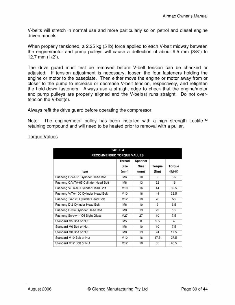
V-belts will stretch in normal use and more particularly so on petrol and diesel engine driven models. When properly tensioned, a 2.25 kg (5 lb) force applied to each V-belt midway between the engine/motor and pump pulleys will cause a deflection of about 9.5 mm (3/8”) to 12.7 mm (1/2”). The drive guard must first be removed before V-belt tension can be checked or adjusted. If tension adjustment is necessary, loosen the four fasteners holding the engine or motor to the baseplate. Then either move the engine or motor away from or closer to the pump to increase or decrease V-belt tension, respectively, and retighten the hold-down fasteners. Always use a straight edge to check that the engine/motor and pump pulleys are properly aligned and the V-belt(s) runs straight. Do not over-tension the V-belt(s). Always refit the drive guard before operating the compressor. Note: The engine/motor pulley has been installed with a high strength Loctite™ retaining compound and will need to be heated prior to removal with a puller. Torque Values
TABLE 4
RECOMMENDED TORQUE VALUES
Item
Thread
Size
(mm)
Spanner
Size
(mm)
Torque
(Nm)
Torque
(lbf-ft)
Fusheng C/VA-51 Cylinder Head Bolt M6 10 9 6.5
Fusheng C/V/TA-65 Cylinder Head Bolt M8 13 22 16
Fusheng V/TA-80 Cylinder Head Bolt M10 16 44 32.5
Fusheng V/TA-100 Cylinder Head Bolt M10 16 44 32.5
Fusheng TA-120 Cylinder Head Bolt M12 18 76 56
Fusheng D-2 Cylinder Head Bolt M6 10 9 6.5
Fusheng D-3/4 Cylinder Head Bolt M8 13 22 16
Fusheng Screw-In Oil Sight Glass M27 27 10 7.5
Standard M5 Bolt or Nut M5 8 5.5 4
Standard M6 Bolt or Nut M6 10 10 7.5
Standard M8 Bolt or Nut M8 13 24 17.5
Standard M10 Bolt or Nut M10 16 37.5 27.5
Standard M12 Bolt or Nut M12 18 55 40.5

Airmac Owner’s Manual
August 2006 © Glenco Manufacturing Pty Ltd Page 31 of 44
Air Tightness While the air receiver tank is pressurized to at least 650 kPa (94 psi) and the compressor is switched off, listen for any audible air leaks. Squirt soapy water around any suspect joint and watch for bubbles indicating a leak. De-pressurize the air receiver tank carefully and all connected air hoses and/or air piping before commencing any repairs. Disassemble the leaking joint and clean off all traces of thread tape or sealant using a wire brush. Apply PTFE thread tape or Loctite™ 243 liquid sealant to the male threaded connection before reassembling and tightening the joint. Allow approximately 30 minutes for the liquid sealant to cure, if used. Re-pressurize the air receiver tank and check that the air leak has been rectified before putting the unit back into normal operation. Pressure Switch and Pilot Valve The cut-in and cut-out pressures have been preset at the factory and should not be altered. There are no user serviceable parts within these components. 12 Volt Battery If installed, the factory fitted 12 Volt battery is a maintenance free type. Ensure correct polarity whenever charging or refitting the battery as described in the Installation section.
Airmac Owner’s Manual
August 2006 © Glenco Manufacturing Pty Ltd Page 32 of 44
TROUBLESHOOTING Before performing any inspection, test or repair work on the compressor, switch off the unit, tag and lock out the power supply or disconnect the engine spark plug, and carefully release all air pressure from the receiver tank, air hoses and/or air piping. Please refer to the troubleshooting guide shown in Table 5 for assistance with diagnosing and repairing any problem that might occur with your air compressor. Whilst many of the tasks can be undertaken by a mechanically proficient person with access to proper tools, all electrical work must by undertaken by a licensed electrician. It is recommended for your convenience and expedience that the troubleshooting guide is consulted prior to contacting an Airmac dealer or Glenco Manufacturing Pty Ltd for advice. Refer to the separate Owner’s Manual for instructions about the petrol or diesel engine, if fitted. Use only genuine spare parts for maintenance and repair of the compressor to ensure its safe and reliable operation. For best results, the following repair procedures should always be observed:
• Use new gaskets, seals and O-rings during reassembly.
• Use PTFE thread tape or Loctite™ sealant on threaded joints subject to pressure.
• Use Loctite™ retaining compound when fitting engine or motor pulleys onto their drive shafts.

Airmac Owner’s Manual
August 2006 © Glenco Manufacturing Pty Ltd Page 33 of 44
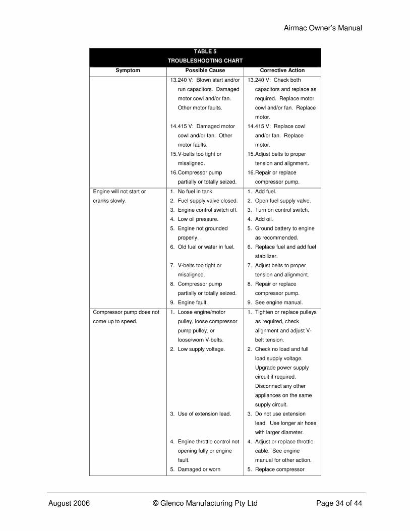
TABLE 5
TROUBLESHOOTING CHART
Symptom Possible Cause Corrective Action
Motor will not start, runs
slowly or repeatedly trips out
overload protection.
1. Pressure switch not
turned on.
2. Air receiver tank pressure
above cut-in pressure.
3. No voltage at the
pressure switch.
4. No voltage at the electric
motor (faulty pressure
switch, dual DOL starter
or star-delta starter).
5. No voltage on one or two
phases of 415 V supply.
6. Low supply voltage.
7. Use of extension lead.
8. 240 V: Thermal overload
switch on motor tripped.
9. 415 V: Thermal overload
relay in pressure switch
tripped.
10. 415 V: Thermal overload
relay in star-delta starter
tripped.
11. Faulty pressure switch
unloader valve (nil or
restricted unloading air
flow).
12. Nil or restricted discharge
air flow through non-
return valve.
1. Turn on pressure switch.
2. Nil (no fault).
3. Check electricity supply
including all fuses, circuit
breakers, switches and
wiring.
4. Repair or replace
pressure switch, dual
DOL starter or star-delta
starter.
5. Check voltage on all three
phases of 415 V supply.
6. Check no load and full
load supply voltage.
Upgrade power supply
circuit if required.
Disconnect any other
appliances on the same
supply circuit.
7. Do not use extension
lead. Use longer air hose
with larger diameter.
8. 240 V: Allow motor to
cool down and manually
reset overload switch.
9. 415 V: Allow motor to
cool down and manually
reset pressure switch to
the “AUTO” position.
10. 415 V: Allow motor to
cool down and manually
reset overload relay
(located inside the star-
delta enclosure).
11. Replace unloader valve or
complete pressure switch.
12. Repair or replace non-
return valve.
Airmac Owner’s Manual
August 2006 © Glenco Manufacturing Pty Ltd Page 34 of 44
TABLE 5
TROUBLESHOOTING CHART
Symptom Possible Cause Corrective Action
13. 240 V: Blown start and/or
run capacitors. Damaged
motor cowl and/or fan.
Other motor faults.
14. 415 V: Damaged motor
cowl and/or fan. Other
motor faults.
15. V-belts too tight or
misaligned.
16. Compressor pump
partially or totally seized.
13. 240 V: Check both
capacitors and replace as
required. Replace motor
cowl and/or fan. Replace
motor.
14. 415 V: Replace cowl
and/or fan. Replace
motor.
15. Adjust belts to proper
tension and alignment.
16. Repair or replace
compressor pump.
Engine will not start or
cranks slowly.
1. No fuel in tank.
2. Fuel supply valve closed.
3. Engine control switch off.
4. Low oil pressure.
5. Engine not grounded
properly.
6. Old fuel or water in fuel.
7. V-belts too tight or
misaligned.
8. Compressor pump
partially or totally seized.
9. Engine fault.
1. Add fuel.
2. Open fuel supply valve.
3. Turn on control switch.
4. Add oil.
5. Ground battery to engine
as recommended.
6. Replace fuel and add fuel
stabilizer.
7. Adjust belts to proper
tension and alignment.
8. Repair or replace
compressor pump.
9. See engine manual.
Compressor pump does not
come up to speed.
1. Loose engine/motor
pulley, loose compressor
pump pulley, or
loose/worn V-belts.
2. Low supply voltage.
3. Use of extension lead.
4. Engine throttle control not
opening fully or engine
fault.
5. Damaged or worn
1. Tighten or replace pulleys
as required, check
alignment and adjust V-
belt tension.
2. Check no load and full
load supply voltage.
Upgrade power supply
circuit if required.
Disconnect any other
appliances on the same
supply circuit.
3. Do not use extension
lead. Use longer air hose
with larger diameter.
4. Adjust or replace throttle
cable. See engine
manual for other action.
5. Replace compressor
Airmac Owner’s Manual
August 2006 © Glenco Manufacturing Pty Ltd Page 35 of 44
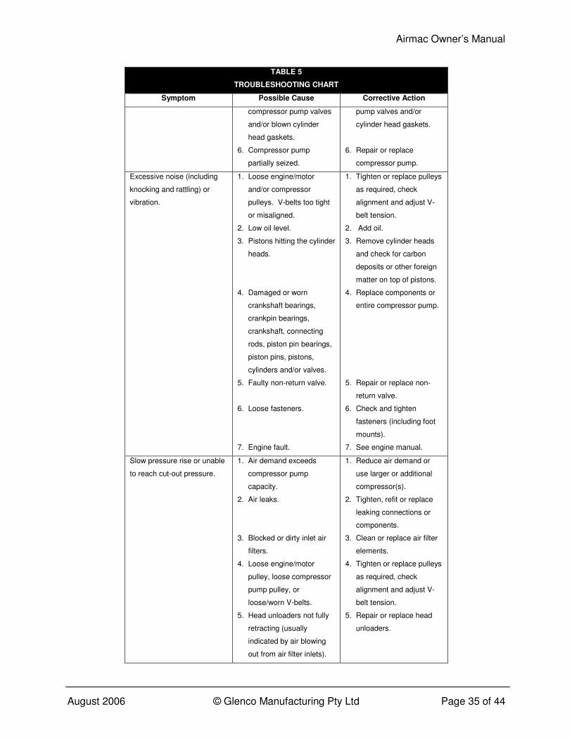
TABLE 5
TROUBLESHOOTING CHART
Symptom Possible Cause Corrective Action
compressor pump valves
and/or blown cylinder
head gaskets.
6. Compressor pump
partially seized.
pump valves and/or
cylinder head gaskets.
6. Repair or replace
compressor pump.
Excessive noise (including
knocking and rattling) or
vibration.
1. Loose engine/motor
and/or compressor
pulleys. V-belts too tight
or misaligned.
2. Low oil level.
3. Pistons hitting the cylinder
heads.
4. Damaged or worn
crankshaft bearings,
crankpin bearings,
crankshaft, connecting
rods, piston pin bearings,
piston pins, pistons,
cylinders and/or valves.
5. Faulty non-return valve.
6. Loose fasteners.
7. Engine fault.
1. Tighten or replace pulleys
as required, check
alignment and adjust V-
belt tension.
2. Add oil.
3. Remove cylinder heads
and check for carbon
deposits or other foreign
matter on top of pistons.
4. Replace components or
entire compressor pump.
5. Repair or replace non-
return valve.
6. Check and tighten
fasteners (including foot
mounts).
7. See engine manual.
Slow pressure rise or unable
to reach cut-out pressure.
1. Air demand exceeds
compressor pump
capacity.
2. Air leaks.
3. Blocked or dirty inlet air
filters.
4. Loose engine/motor
pulley, loose compressor
pump pulley, or
loose/worn V-belts.
5. Head unloaders not fully
retracting (usually
indicated by air blowing
out from air filter inlets).
1. Reduce air demand or
use larger or additional
compressor(s).
2. Tighten, refit or replace
leaking connections or
components.
3. Clean or replace air filter
elements.
4. Tighten or replace pulleys
as required, check
alignment and adjust V-
belt tension.
5. Repair or replace head
unloaders.
Airmac Owner’s Manual
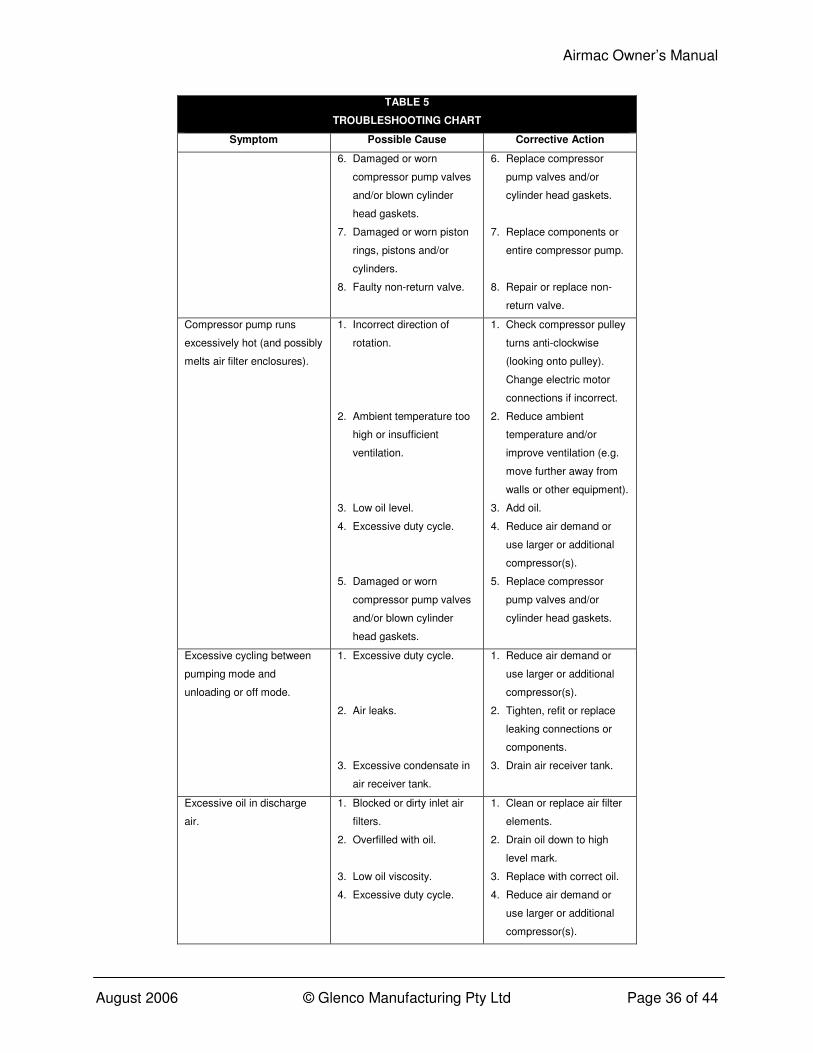
August 2006 © Glenco Manufacturing Pty Ltd Page 36 of 44
TABLE 5
TROUBLESHOOTING CHART
Symptom Possible Cause Corrective Action
6. Damaged or worn
compressor pump valves
and/or blown cylinder
head gaskets.
7. Damaged or worn piston
rings, pistons and/or
cylinders.
8. Faulty non-return valve.
6. Replace compressor
pump valves and/or
cylinder head gaskets.
7. Replace components or
entire compressor pump.
8. Repair or replace non-
return valve.
Compressor pump runs
excessively hot (and possibly
melts air filter enclosures).
1. Incorrect direction of
rotation.
2. Ambient temperature too
high or insufficient
ventilation.
3. Low oil level.
4. Excessive duty cycle.
5. Damaged or worn
compressor pump valves
and/or blown cylinder
head gaskets.
1. Check compressor pulley
turns anti-clockwise
(looking onto pulley).
Change electric motor
connections if incorrect.
2. Reduce ambient
temperature and/or
improve ventilation (e.g.
move further away from
walls or other equipment).
3. Add oil.
4. Reduce air demand or
use larger or additional
compressor(s).
5. Replace compressor
pump valves and/or
cylinder head gaskets.
Excessive cycling between
pumping mode and
unloading or off mode.
1. Excessive duty cycle.
2. Air leaks.
3. Excessive condensate in
air receiver tank.
1. Reduce air demand or
use larger or additional
compressor(s).
2. Tighten, refit or replace
leaking connections or
components.
3. Drain air receiver tank.
Excessive oil in discharge
air.
1. Blocked or dirty inlet air
filters.
2. Overfilled with oil.
3. Low oil viscosity.
4. Excessive duty cycle.
1. Clean or replace air filter
elements.
2. Drain oil down to high
level mark.
3. Replace with correct oil.
4. Reduce air demand or
use larger or additional
compressor(s).
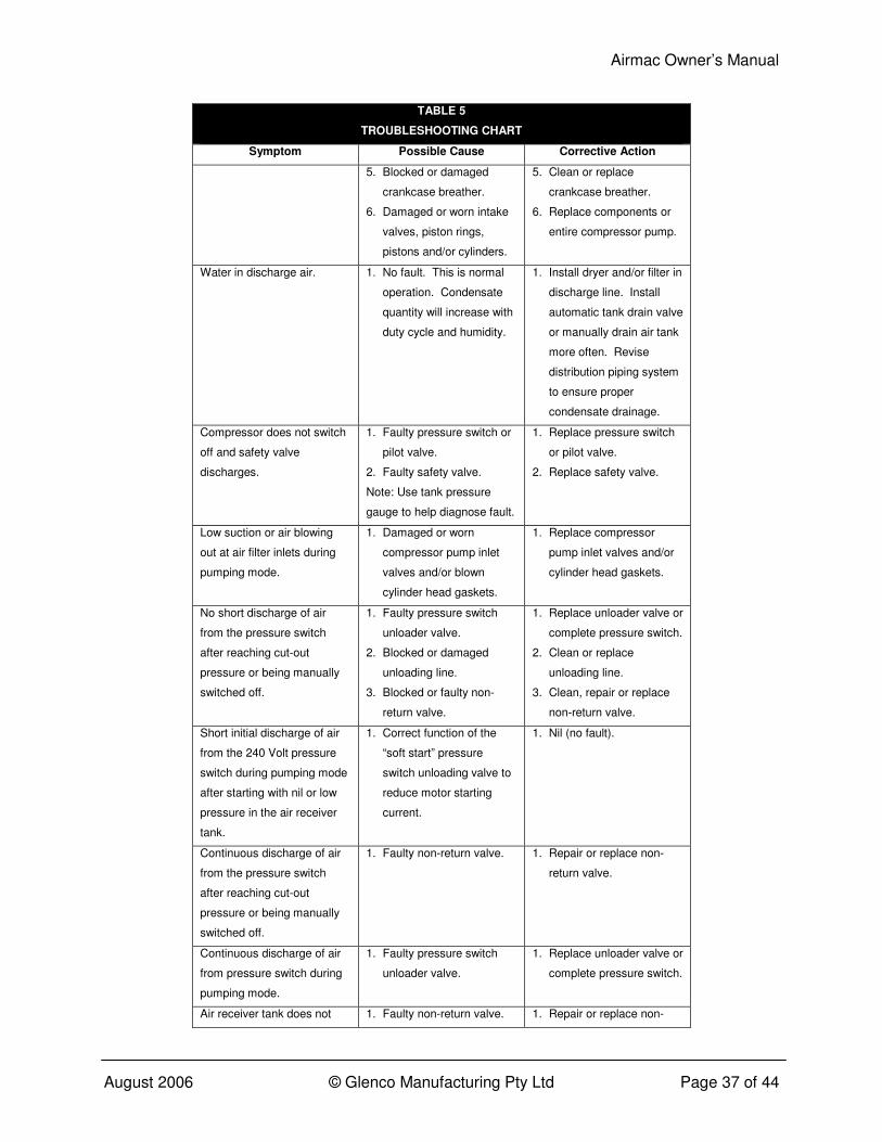
Airmac Owner’s Manual
August 2006 © Glenco Manufacturing Pty Ltd Page 37 of 44
TABLE 5
TROUBLESHOOTING CHART
Symptom Possible Cause Corrective Action
5. Blocked or damaged
crankcase breather.
6. Damaged or worn intake
valves, piston rings,
pistons and/or cylinders.
5. Clean or replace
crankcase breather.
6. Replace components or
entire compressor pump.
Water in discharge air. 1. No fault. This is normal
operation. Condensate
quantity will increase with
duty cycle and humidity.
1. Install dryer and/or filter in
discharge line. Install
automatic tank drain valve
or manually drain air tank
more often. Revise
distribution piping system
to ensure proper
condensate drainage.
Compressor does not switch
off and safety valve
discharges.
1. Faulty pressure switch or
pilot valve.
2. Faulty safety valve.
Note: Use tank pressure
gauge to help diagnose fault.
1. Replace pressure switch
or pilot valve.
2. Replace safety valve.
Low suction or air blowing
out at air filter inlets during
pumping mode.
1. Damaged or worn
compressor pump inlet
valves and/or blown
cylinder head gaskets.
1. Replace compressor
pump inlet valves and/or
cylinder head gaskets.
No short discharge of air
from the pressure switch
after reaching cut-out
pressure or being manually
switched off.
1. Faulty pressure switch
unloader valve.
2. Blocked or damaged
unloading line.
3. Blocked or faulty non-
return valve.
1. Replace unloader valve or
complete pressure switch.
2. Clean or replace
unloading line.
3. Clean, repair or replace
non-return valve.
Short initial discharge of air
from the 240 Volt pressure
switch during pumping mode
after starting with nil or low
pressure in the air receiver
tank.
1. Correct function of the
“soft start” pressure
switch unloading valve to
reduce motor starting
current.
1. Nil (no fault).
Continuous discharge of air
from the pressure switch
after reaching cut-out
pressure or being manually
switched off.
1. Faulty non-return valve. 1. Repair or replace non-
return valve.
Continuous discharge of air
from pressure switch during
pumping mode.
1. Faulty pressure switch
unloader valve.
1. Replace unloader valve or
complete pressure switch.
Air receiver tank does not 1. Faulty non-return valve. 1. Repair or replace non-
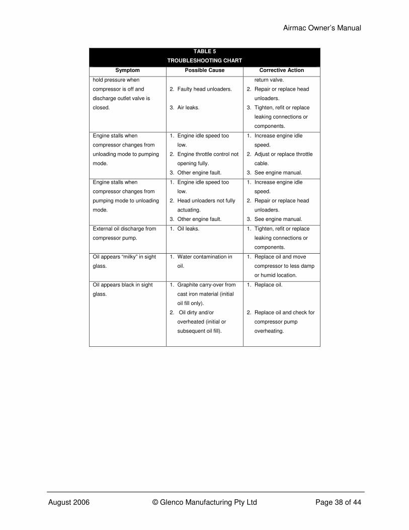
Airmac Owner’s Manual
August 2006 © Glenco Manufacturing Pty Ltd Page 38 of 44
TABLE 5
TROUBLESHOOTING CHART
Symptom Possible Cause Corrective Action
hold pressure when
compressor is off and
discharge outlet valve is
closed.
2. Faulty head unloaders.
3. Air leaks.
return valve.
2. Repair or replace head
unloaders.
3. Tighten, refit or replace
leaking connections or
components.
Engine stalls when
compressor changes from
unloading mode to pumping
mode.
1. Engine idle speed too
low.
2. Engine throttle control not
opening fully.
3. Other engine fault.
1. Increase engine idle
speed.
2. Adjust or replace throttle
cable.
3. See engine manual.
Engine stalls when
compressor changes from
pumping mode to unloading
mode.
1. Engine idle speed too
low.
2. Head unloaders not fully
actuating.
3. Other engine fault.
1. Increase engine idle
speed.
2. Repair or replace head
unloaders.
3. See engine manual.
External oil discharge from
compressor pump.
1. Oil leaks. 1. Tighten, refit or replace
leaking connections or
components.
Oil appears “milky” in sight
glass.
1. Water contamination in
oil.
1. Replace oil and move
compressor to less damp
or humid location.
Oil appears black in sight
glass.
1. Graphite carry-over from
cast iron material (initial
oil fill only).
2. Oil dirty and/or
overheated (initial or
subsequent oil fill).
1. Replace oil.
2. Replace oil and check for
compressor pump
overheating.
Airmac Owner’s Manual
August 2006 © Glenco Manufacturing Pty Ltd Page 39 of 44
TRANSPORT Always de-pressurize the air receiver tank before transporting the air compressor. Turn the engine fuel valve off, if fitted, and always keep the compressor level to prevent oil and/or fuel spillage. Ensure that adequate lifting equipment is available for moving and loading the compressor. Lifting equipment, slings, etc. must be properly rated for the weight of the compressor. Take care when attaching load restraining devices to ensure that the compressor does not tip over during transport, especially because of its high centre of gravity. Check with the carrier whether lubricating oil and/or engine fuel must be drained out prior to transport. If so, ensure that the party receiving the compressor is notified accordingly. Keep the compressor covered during transport to prevent the ingress of dust and debris.

Airmac Owner’s Manual
August 2006 © Glenco Manufacturing Pty Ltd Page 40 of 44
STORAGE Always de-pressurize and drain the air receiver tank before storing the air compressor. Turn the engine fuel valve off, if fitted, and always keep the compressor level to prevent oil and/or fuel spillage. Store the compressor in a cool, dry and shaded place and keep it covered to prevent the ingress of dust and debris. If storing the compressor for a long period, the following additional preparations should be made:
• Change the compressor pump lubricating oil and clean the entire unit in accordance with the maintenance instructions.
• Petrol air compressors: Check that the engine control switch is turned off and drain all petrol from the fuel tank and piping. Remove the spark plug and pour about a tablespoon of clean engine oil into the cylinder. Crank the engine several revolutions to distribute the oil and then reinstall the spark plug. Remove the 12 volt battery, if fitted, and recharge it once a month.
• Diesel air compressors: Check that the engine control switch is turned off and drain all diesel from the fuel tank and piping. Pull the starter handle slowly until strong resistance is felt and then return it slowly. At this point, the engine’s inlet and exhaust valves should be closed during the compression stroke and this should help to prevent rust forming inside the cylinder while the engine is not is use.

Airmac Owner’s Manual
August 2006 © Glenco Manufacturing Pty Ltd Page 41 of 44
DISMANTLING AND DISPOSAL There is no requirement for the air compressor to be dismantled during normal operation other than for major repair/overhaul or prior to final disposal at the end of its service life. Dismantling should only be carried out by a mechanically proficient person with access to proper tools or alternatively by your Airmac dealer for a fee. Before dismantling the compressor, switch off the unit, disconnect the power supply, turn off the fuel supply valve, carefully de-pressurize and drain the air receiver tank, drain out the fuel tank and piping, and drain the lubricating oil from the compressor pump and engine. Do not pollute the environment by improper or illegal disposal of the waste oil, fuel and condensate. Air receiver tanks should be rendered unusable for pressure service prior to disposal, for example by cutting or massive deformation. This is to prevent their unauthorized and unsafe use by others. Do not pollute the environment by improper or illegal disposal of the compressor either as a whole or dismantled. Take the unwanted unit or components to your local recycling centre instead. The compressor is almost entirely made of metal that can usually be sold to scrap metal recyclers.
Airmac Owner’s Manual
August 2006 © Glenco Manufacturing Pty Ltd Page 42 of 44
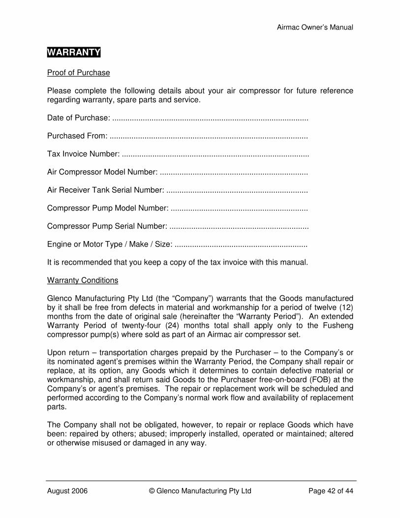
WARRANTY Proof of Purchase Please complete the following details about your air compressor for future reference regarding warranty, spare parts and service. Date of Purchase: .......................................................................................... Purchased From: ........................................................................................... Tax Invoice Number: ...................................................................................... Air Compressor Model Number: .................................................................... Air Receiver Tank Serial Number: ................................................................. Compressor Pump Model Number: ............................................................... Compressor Pump Serial Number: ................................................................ Engine or Motor Type / Make / Size: ............................................................. It is recommended that you keep a copy of the tax invoice with this manual. Warranty Conditions Glenco Manufacturing Pty Ltd (the “Company”) warrants that the Goods manufactured by it shall be free from defects in material and workmanship for a period of twelve (12) months from the date of original sale (hereinafter the “Warranty Period”). An extended Warranty Period of twenty-four (24) months total shall apply only to the Fusheng compressor pump(s) where sold as part of an Airmac air compressor set. Upon return – transportation charges prepaid by the Purchaser – to the Company’s or its nominated agent’s premises within the Warranty Period, the Company shall repair or replace, at its option, any Goods which it determines to contain defective material or workmanship, and shall return said Goods to the Purchaser free-on-board (FOB) at the Company’s or agent’s premises. The repair or replacement work will be scheduled and performed according to the Company’s normal work flow and availability of replacement parts. The Company shall not be obligated, however, to repair or replace Goods which have been: repaired by others; abused; improperly installed, operated or maintained; altered or otherwise misused or damaged in any way.
Airmac Owner’s Manual
August 2006 © Glenco Manufacturing Pty Ltd Page 43 of 44
The Company shall not be responsible for any diagnosis, communication, dismantling, packing, handling, freight, and reassembly or reinstallation charges. Freight damage, pre-delivery service, normal operating adjustments, preventative maintenance service, consumable items, cosmetic damage, corrosion, erosion, normal wear and tear, performance, merchantability, and fitness for a particular purpose are not covered under this Warranty. The Company shall not be liable for any repairs, replacements, or adjustments to the Goods or any costs of labour performed by the Purchaser without the Company’s prior written approval. Accessories or components furnished by the Company, but manufactured by others – including, but not limited to electric motors, petrol engines and diesel engines – shall carry whatever warranty the manufacturer conveyed to the Company and which can be passed on to the Purchaser. This Warranty is in lieu of all other warranties, expressed or implied. To the extent permissible by law and notwithstanding any other clause in these Warranty Conditions, the Company excludes all liability whatsoever to the Purchaser arising out of or in any way connected with a contract for any consequential or indirect losses of any kind howsoever arising and whether caused by breach of statute, breach of contract, negligence or other tort. The Company’s liability will be limited to, in the case of products, the replacement of the products, the supply of equivalent products or the payment of the cost of replacing the products or of acquiring equivalent products or, in the case of services, the supply of the services again or the payment of the cost of having the services supplied again. The choice of remedy will be at the discretion of the Company and the Purchaser acknowledges that this limitation of liability is fair and reasonable.
Airmac Owner’s Manual
August 2006 © Glenco Manufacturing Pty Ltd Page 44 of 44
MAINTENANCE AND REPAIR RECORD
Date Maintenance or Repair Activity