Embed Size (px)
Citation preview

OWNERMANUAL

FORWARD
The operating instruct ions and maintenance recommendations in this manual wi l l help you getacquainted with, and get the most satisfactory performancefrom yournew Hardin Marine Engine.How well your engine wil l del iverthe performance i t has bui l t into i t depends in the care i t receives.This manual contains a l ist ing of maintenance procedures that should be performed at recom-mended intervals. The operator orservice personnel responsible forthe care of this engine shouldbe thoroughly famil iar with these procedures.
This manual covers the ful l l ine of Hardin Gasoline Engines. These engines have many dif fer-ences, however the operation and service is the same on al l these engines. In this manual we wil lcover the basic operation and service as well as some of the differences between engine models.
Hardin Marine takes pride in producing engines of qual i ty for a wide variety of marine applica-t ions. Engines that have been created through a great deal of research using high quali ty parts toachieve the upmost in performance and durabi l i ty.
Should a need for replacement parts or service develop, contact Hardin Marine or the HardinMarine Authorized Dealer near vou.

PAGEIMPORTANT OWNER REGISTRATION . . . . . . . . . . , . . .2
INFORMATIONWarranty Form . . . . . . . . . . .2Warranty Card . . , , , . . . . . ,2Engine Ser ia l Number . . . . . . . . . . . .2
PRE DELIVERY INSPECTION . . . . . . . . . . . . , . .3
owNERS RESPONS|B|L|T|ES . . . . . . . . . . . . . .410 Hour Inspect ions . , . , . .4
ENGINE SPECIFICATIONS , . . . . . .5.9
OPERATING INSTRUCTIONS . . . . . . . . . 10-14Start ingEngine. . . . . . . . .10Operat ingTheHeader(GateValve) . . . . .11Operat ing Hints . . . . . . . . 1210 Hour Break- in Per iod . . . . . . . . 13lnstruments . . , .14
LUBRTCATION . . . . . . . . 15-17EngineOi l . . , . . . . . . . 15-16Engine Oi l Draining Prodedure . . . . . . . . . . 17Universal Dr ive Lines . . . . . . . . . . . 17Thrott le Cable. . . . . . . . . . . . . . . . . . 17Crankcase Breather Filter . . ..... . 17PCV Valve . . . . . 17MaintenanceServiceOhart . . . . . . 18
TABLE OF CONTENTS "'
. PAGE
COOLING SYSTEMSDescription . 19-20Salt Water Operat ion . . . . . . . . . . . 20Flushing Procedure . . . . .21
ELECTRICAL SYSTEMS , . . . . . , 22-23Alternator . . . . . . 22Battery. . . . . . . . .22Spark Plugs . 22-23
FUEL SYSTEM ,. . . . . . . 23.24Fuel Pumo . . . . . 23Fi l ter . . . . . . . . . . . 23Type Fuel . . . . . . 23Carburetor , . , . . 24
TROUBLE SHOOTING , . , . . . . , 25-27
WINTER STORAGE ,, 28-29
PREPARATION OF ENGINE FOR SERVICE . . . . . . . 30
WIRING DIAGRAM .. . , 31-33
WARRANTY SERVICE . . . . . Inside Back Cover
WARRANTY STATEMENT . . . . . . . .Back Cover
IMPORTANT INFORMATION ISPOINTED OUT BY BOLD RED TYPE.

IMPORTANT OWNER'FEGTSTRATTON TNFORMATTON
WARRANTY FORMIncluded with this manual is a warranty form which must be f illed oul and
mailed to Hardin Marine to iniliate the warranty on your new Hardin engineand/or drive.
This form is pre-addressed to Hardin Marine and should be f i l led out byyou and your dealer at the t ime of purchase. Please f i l l out the card com-pletely, including the engine model and serial number and mail i t within 10days of purchase date.
NOTE: The Federal Boat Safety Act of 1971 requires that registrat ionl ists of marine products sold in the United States be maintainedby the manufacturers and dealers of these products. Therefore, i tis extremely important that we receive your registrat ion formboth for warranty purposes and to comply with federal regula-t ions. This product owner information wil l also enable us to con-tact you should i t become necessary to change or improve theproduct to protect the well being of you, the owner andoperator.
WARRANTY CARDWhen the completed warranty form is received by Hardin Marine, a
plastic Owner's Warranty Card wil l be made and sent direct ly to you. Thiswarranty card is your only val id identi f icat ion for warranty work and mustbe presented to a Hardin Authorized Service Dealer for warrantv work.
FAILURE TO RETURN WARRANTY FORM CONSTITUTES AWAIVER OF ANY NOTIFICATION AS DESCRIBED IN THE 1971FEDERAL BOAT SAFETY ACT.
ENGINE SERIAL NUMBERThe serial number should be recorded on the warranty form supplied
with this manual and should be relerred to in any correspondence concern-ing your engine. This n.umber wrl l be rmprinted on your warranty cardwhich must be used whenever any warranty repairs are made on thisengine.
The engine serial number is stamped onto the engine block or head onthe port (left) side of the lronl ol the engine as indicated by the arrowsbelow. (See figure 1).
MODELH320
MODELSH20s, H225,H280, H333,H405. H425.
H260H400H430
FIGURE 1
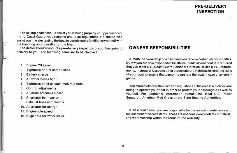
The selling dealer should assist you in being properly equipped accord-ing to Coast Guard requirements and local regulat ions. He should alsoassist you in watertesting the boat to permityou to familiarize yourself withthe handling and operation of the boat.
The dealer should conduct a pre-delivery inspiection of your boat priortodel ivery to you. The fol lowing i tems are to be checked:
1. Engine Oil Level2. Tightness of fuel and oi l l ines
3. Battery charge4. Al l water hoses t ight
5. Tightness of al l exhaust manifold nuts6. Control adjustments
7. Al l drain petcocks closed8. Alternator belt tension
9. Exhaust hose and clamps10. Alternator for charge11. Engine id le speed12. Bilge area for water leaks
PRE-DELIVERYINSPECTION
OWNERS RESPONSIBILITIES
A. With the ownership of a new boat you receive certain responsibi l i t ies.By law you are now responsible for al loccupants of your boat. l t is reguiredthat you meet U.S. Coast Guard Personal Flotat ion Device (PFD) require-ments. Instruct at least one other person aboard in the basic handling ski l lsof your boat to enable that person to operate the boat in case of an emer-gency.
You should observe the rules and regulat ions of the area in which you aregoing to operate your boat in order to protect your passengers as well asyourself. For addit ional information contact the local U.S. PowerSquadron, American Red Cross or the State Boating Authorit ies.
B. As a boat owner, you are responsible for the normal maintenance andreplacement of service items. These are not considered defects in materialand workmanship within the terms ol the warranty.

i
OWNER'SRESPONSIBILITIES
1O HOUR INSPECTIONTo insure that you receive the maximum service from your Hardin equip-
ment you should ask your Hardin Dealer about a 10 hour service and in-
spect ion af ter the f i rst 10 hours of operat ion. ALTHOUGH THE 10 HOUR
SERVICE lS NOT COVERED UNDER THE WARRANTY POLICY' the cost
to you wi l l be minimal and should a malfunct ion be found and corrected at
th is t ime. the inspect ion wi l l pay for i tsel f many t imes over.
The {ol lowing is a l ist ol i tems to check or service:
1. Check for oi l , fuel or water leaks.
2. Drain oi l and replace f i l ter . (see oi l change). pg. 15-17
3. Check and re{ ighten engine mount bol ts.
4. Check fuel l ine f i t t ings for t ightness.
5. Check hose clamPs and hoses.
6. Check the alternator belt for correct tension'
7. Check thrott le l inkage.
B. Check the f lame arrestor '
9. Check the fuel f i l ter.
10. Check al l electr ical connections for t ightness.
11. Check exhaust manifold bol ts for t ightness
12. Check the bi lge pump and blower for operation'
13. Check al l switches, l ights, and other equipment for operation'
14. Launch the boat.
15. Start the engine and check thet iming and dwel lof thedistr ibutor '
16. Check the operation of al l the instruments.
17. Check the carburetor adjustments.
18. Check for overheating at maximum RPM's, and at idle RPM's'
19. Check the operation of the steering and shif t ing system'
l f any del ic iencies, ma|funct ions or SignS of abuse exist in the 1o-hour
inspection, i t shou|d be noted, brought to your attention, and corrected at
thar t ime.
NOTE: l f defects are found in the equipment that is not supplied by
Hardin Marine, please contact that manufacturer for serv'ce
inf ormation.

ENGINE
H 205 H 225 H 260 H 280
Net Horsepower.-BoreStrokeDisplacementCompression RatioFuel RequirementsFuel Pump Pressureldle RPM In Waler Jetld le RPM l /OV or Direct DriveMax. Becommended RPMPoint DwellTiming
Spark PIugsPlug capFiring OrderNormal Oi l Pressure @ 1500 RpMOil Viscosity and TypeOi l Capaci ty wi th Fi t terOi l Fi l ter ModelTransmission OilViscosity and TypeMinimum Battery Rat ingAlternator RatingAlternator N4odelDistributor ModelNormal Water Temp.Maximum Temp.
zvc
4.0003.480262 C.t .9.3:1Reg. 87 Oct.6-7 PSI850 RPM
4600 RPM390
80 BTDC@600 RPMACMR43T.035165432
35-45 PStSAE 30 Class SF, SE5 Quart Approx.AC PF 51
See Note1ot2
73 Amp35 AmpI MR 2051 FPrestolite'1200-1800F
2000F
2253.743.48305 C.t .8.5:1Reg. 87 Oct.4-7 PSI8OO RPM750 RPM
44OO RPM26" Each8. BTDC@700 RPMMR43T.03s
18436572
30-45 PSISAE 30 Class SFSE6 QuartAC PF 25
See Note1ot2
73 Amp35 AmpI MR 2051 FYL 67OAV 21200-1800F2000F
A+r
2604.003.48350 C.l.9:1Reg. 87 Oct.4-7 PSI8OO RPM750 RPM
44OO RPM260 Each8 BTDC@700 RPMMR43T.UJC
18436572
30-45 PSISAE 30 Class SF.SE6 QuartAC PF 25
See Note1or2
73 Amp35 Amp8 MR 2051 FYL 67OAV 21200- 180"F2000F
280 I4.oo I
:,T" I9:1 |Res.87 oct. I4-7 Psr I800 RPM I800 RPM
I5000 RPM I260 Each I8 BrDC@700 RPyMR43r
I.o3s I18436572 |3o-4s PSt ISAE 30 Class SF$E6 Quart IACPF25
|See Note
I1or2 |
73 Amp I35 Amp I8MR20s1F IYL 670AV 2 |12Oo-18OoF
I200oF I
I
,\320 //q
' t ty '+.Jo V3.850 \
460 C. l .8:1Reg. 87 Oct.5-7 PSI9OO RPM750 RPM
4600 RPM31.8 BTDC@550 RPT/AHF 32.03s15426378
35-65 PSI /SAE s0 Class SFSE I6 Ouart I
ctAz 6731 ASee Note
1or2 I
73 Amp I
3s Amp I8MR20s1F iD3JL 12100 |120"-180.F I200oF
Itl
t' Horsepower Figures Are ApproximateAnd lvlay Vary With Each Installation. YM*r *' 1 Borswarner;M'#
Twin-Disc Transmission SAE 30 Deteroenl

ENGINESPECIFICATIONS
H 333 H 400 0s H 405 H 42s os H 430 0s
Net Horsepower'.
Bore
StrokeDisplacementCompression Ratio
Fuel Requirements
Fuel Pump Pressure
ldle RPM In Water Jet
ld le RPM l /O V
Or Direct Drive
I/ax. Recommended RPM
Point Dwell
TimingSpark Plugs
Spark Plug Gap
Frnng uroer
Normal Oi l Pressure @ 1500 RPM
Oil Viscosi ty and TYPe
Oil Capacity with Filter
Oi l Fi l ter Model
Transmission Oi l
Viscosity and TyPe
Minimum Battery Rat ing
Alternator Rating
Alternator Model
Distr ibutor Model
Normal Water TemP.
Maximum TemP.
3334.254.0454 c. l .
8:1Reg. 87 Oct.
4-7 PSI
850 RPM
750 FIPM
4600 RPM260 Each
I BTDC@700 RPM
MR43T.03518436572
30-45 PSI
SAE 30 Class SF.SE
6 QuartAC PF 25
See Note1or2
73 Amp35 Amp
8 MR 205'1 F
YL 67OAV 2
1200-1800F2000F
4004.254.0454 C. l .
8.8:'1Reg. 87 Oct.
4.7 PSI
850 RPM
750 RPM
5OOO RPM26" Each
I BTDC@700 RPM
MR 43 T (AC)
.03518436572
30-45 PSI
SAE 30 Class SF.SE
11 QuartFram HP '1
See Note1o(2
73 Amp35 Amp
8 lvR 2051 F
YL 67OAV 2'1200- '180'F
2000F
3604.254.O454 c. l .8.8:1Reg. 87 Oct.
4.7 PSI
850 RPM750 RPM
5OOO RPM26" Each
8 BTDC@7OO RPM
MR 43 r (Ac)
.035
1843657230-45 PSISAE 30 Class SF.SE
6 OuartAC PF 25
See Note
1or2
73 Amp35 Amp
8 MR 2051 F
YL 67OAV 2
120.- 180'F
2000F
4254.254.0454 C. l .8.8:1Reg. 87 Oct.
4.7 PSI
850 RPM
8OO RPM
52OO RPM26'Each
I ETDC@700 RPM
MH 43 T (AC)
.03518436572
30-45 PSI
SAE 30 Class SFSE
11 QuartFram HP 1
See Note1o(2
73 Amp35 Amp
8 tvlR 2051 F
YL 67OAV 2
1200-1800F2000F
4304.254.O454 C. l .
8.8:1Reg. 87 Oct.
4.7 PSI
850 RPM
8OO RPM
52OO RPM260 Each
8 BTDC@7OO RPM
MR 43 T (AC)
.03518436572
30-45 PSI
SAE 30 Class SF.SE'11 QuartFram HP 1
See Note
1ot2
73 Amp35 Amp
8 MR 2051 F
YL 67OAV 2
1200- 1 800F
2000F
"Horsepower Frgures Are Approximate
And May Vary With Each lnstal lat ion.
1. Borgwarner Tiansmission ATF Dextron.
2. Twin-Disc Tiansmission SAE 30 Detergenl5a

ENGINE SPECIFICATIONSMODELS H205,H225, H260, H28O JCt MODELS H225, H260, H280 V-Drive
14
tc
1. Flame Arrestor
2. Carburetor
3. Fuel Pump Vent
4. Fuel Fi l ter
5" Oi l Fi l ler Cap6. Fuel L ine
7. Fuel Pump Inlet
8. Fuel Pump
9. Water lnlet
10. Front Mount11. Rear Mount' t2. Oi l Fi l ter
13. Exhaust Manifold Drain14. Exhaust Riser15. Exhaust Outlet16. PCV Valve
17. Oil Pressure Sender18. Alternator
19. Engine Ser ia l Number20. Starter
21. Oi l Dipst ick
22. Trans Oil Dipstick23. Oil Drain Hose
24. Trans Oil Cooler

IENGINE SPECIFICATIONS
MODELS H333, H4O5 JEt MODELS H333, H405, V'DT|VE
1. Flame Arrestor2. Carburetor3. Fuel Pump Vent4. Fuel Fi l ter5. Oi l Fi l ler Cap6. Fuel L ine
7. Fuel Pump Inlet
8. Fuel Pump
9. Water Inlet
10. Front Mount
11. Rear Mount
12. Oi l Fi l ter
13. Exhaust Manifold14. Exhaust Riser15. Exhaust Outlet16. PCV Valve17. Oi l Pressure Sender
18. Alternator19. Engine Ser ia l Number20. Starter21. Oi l Dipst ick22. Oil Drain Hose

ENGINE SPECIFICATIONSMODELS H260, H280 Tournament Skier MODELS H225, H260, H280, H333, H405
Inboard Fresh Water Gooling
1. Flame Arrestor2. Carburetor3. Fuel Pump Vent4. Fuel Filter5. Oil Fil ler Cap6. Fuel Line
7. Fuel Pump Inlet8. Fuel Pump9. Water lnlet10. Front Mount11. Rear Mount12. Oil Filter
13. Exhaust Manifold Drain14. Exhaust Riser15. Exhaust Outlet16. PCV Valve17. Oil Pressure Sender18. Alternator19. Engine Serial Number
20. Starter21. Oil Dipstick22.Trcns Oil Cooler23. Trans Oil Dipstick24. Oil Drain Hose25. Heat Exchanger26. Radiator Cap

ENGINE
MODELS H333, H405 Inboard l ron
SPECIFICATIONS
MODELS H400, H425, H430 Off Shore
8:",-.'w
4
\
1 Flame Arrestor
2 Carburetor
i r . Fuel PumP Vent
4 Fuel Fi l ter
5 OlFi l lerCaP
6 FLrel Ltne
7 Fuel PumP lnlet
B Fuel PumP
9 Water ln let
10. Front Mount
1 1. Rear Mount
12 Oi l Fi l ter
13. Exhaust Mani lo ld
14 Exhaust Riser (PiPe)
15. Exhaust Out let
16. PCV Valve
17. Oi l Pressure Sender
18. Al ternator
19. Engrne Serral Number
20. Starter
2 '1 . Oi l DiPSt ick
i%*-15
Trans Oi l DiPSt ick
Trans Oi l Cooler
Oi l Drain Hose
Power Steer ing Unit
Oi l Cooler
Thermostat Houslng
22.
24.
25
26
27

FILLING THE FUEL TANKCAUTION: GASOLINE VAPORS ARE EXPLOSIVE. ALWAYS USESAFETY MEASURES WHEN FUELING AND STARTING YOUR ENGINE.
1. Insure that all electrical equipment is turned off.2. Extinguish all open flame and all smoking material.3. The f iller hose nozzle should be in contact with the fill pipe to prevent
sparks.
BEFORE STARTING'1 . Gheck engine, transmission or outdrive for proper oil level.2. Check fuel supply.3. Operate bilge blower for at least 4 minutes prior to cranking the
engine to remove any possible gasoline fumes lrom the enginecompartment.
4. Check that all the engine and exhaust manifold drain plugs on theengine are closed tight.
STARTINGA. Boals equlpped wlth slngle leyer control such aB Morse "MV-J"
1. Place lever in neutral detent.2. Pull button out or pull outward on lever to disengage shifter.3. Pump throttle by moving shift lever full foruard and return two or
three times to prime a cold engine. Do not pump throttle if engine ishot. Throttle should be at idle when starting engine.
4. Turn ignition key to start and as soon as engine starts, release keyand allow switch to return to run position.
OPERATINGINSTRUCTIONS
DO NOT OPERATE STARTER FOR MORE THAN 15 SECONDS WITH-OUT PAUSING TO ALLOW STARTER MOTOR TO COOL FOR 2MINUTES.
B. Boatr equlpped with Foot Throtlle
1. Place shift lever in approximate neutral and place one hand on leverwhile starting. This will enable you to keep the boat in neutral whenthe engine starts.
2. Pump throttle as in an automobile to start cold engine.3. Use starter limitation as listed previously.
AFTER ENGINE STARTS'1 . Check oil pressure - lt should be at or above 10lbs. at idle RPM on a
cold engine.2. Run engine at close to idle until a rise in temperature can be detected
on the temperature guage.3. Place throttle in neutral and push button in to engage shift cable. You
are now ready to get underway.4. Move shift lever forward to place drive in forward and as lever con-
tinues to move forward, throttle will be advanced.
JET DRIVE ENGINES MAY BE RUN WITH BOATOUTOFWATER ONLYIF WATER IS SUPPLIED TO THE INLET WATER HOSE FOR ENGINECOOLING. DO NOT RUN OVER 2OOO RPM OR FOR MORE THAN 1MINUTE OR DAMAGE MAY OCCUR IN THE SEAL AREA OF THE JETDRIVE. IF WATER IS NOT SUPPLIED TO THE ENGINE IT MAY BESTARTED, BUT SHOULD ONLY BE ALLOWED TO RUN FOR A FEWSECONDS. DO NOT START V-DRIVE, I/O OR DIRECT DRIVE ENGINESWITHOUT A WATER SUPPLY AS DAMAGE MAY BE DONE TO THEWATER PUMP.
10

OPERATINGINSTRUCTIONS
CAUTION: KEEP PASSENGERS AWAY FROM HEADER AT ALL TIMES.
ieriune ro Do so couLD RESULT lN SEVERE INJURY'
C. Boats equipped with Water lniected Headers
ln short, allow only enough water to pass through headers to keep
the rest of the chrome from blueing'
Keep belongings anct passengers away from header and engine at al
t imes.
t . The Gate Valve:fn" g"t" u"fu" (see fig. 8) is necessary so that you can regulate the
amoJnt of water that passes through the headers'
Operating the Gate Valve:
A. Turn valve clockwise to allow more water to headers'
B. Turn valve counter clockwise to restrict the amount of water
to headers.C.Generalruletolol low:Thefastertheboatspeed' themore
the valve should be turned clockwise' The slower the boat
speed, the more the valve should be turned counter clock-
wise.
3. When running boat on trai ler, make sure nose of boat is elevated'
Always fol low this Procedure:START ENGINE, TURN ON WATER. TURN OFF WATER' STOP
ENGINE ON JETS ONLY.
4. For V-Drive engines or engines equipped with an engine driven
water PumP fol low this Procedure:TURN ON WATER, START ENGINE. STOP ENGINE, TURN OFF
WATER.
Water inlected headers are DRY and HOT at idle They are also hot
the f i rst '6 inches out from the head to the water inlet f i t t ing and the
chrome wil l blue to this Point '
Fai lure to do any of above, or i f system is not working correctly could
result in SEVERE ENGINE DAMAGE'o.
Gate ValveFigure 8
11

OPERATING HINTS FOR BOAT OWNERSA. When launching your boat, do not back the trailer in at a fast pace and
"hit the brakes" to "shoot the boat off the trailer". This launching tech_nique could force water up the exhaust port and into the engine whichcould cause severe damage to the engine. The flappers in the exhaustports and the risers on the exhaust manifold are designed to preventthis from happening under normal use. (See f igure 9).
FIG. 9
NOTE: lf the engine should develop a hydro-static lock (water drawninto the cyl inder through the exhaust system) the fol lowing stepsshould be taken:
1. Loosen the connection between the exhaust r iser and the exhaustmanifold. This wil l al low any water that is trapped inside the exhaustchamber to drain out. Retighten the r iser.
2. Remove al l spark plugs, remove the center wire of the coi l , and crankengine for 15 seconds.
3. Squirt approximately 1 teaspoon of motor oi l in each cyl inder andcrank engine again for 1S seconds.
4. Replace spark plugs, re-instal l the coi l wire, and start engine.
" l f engine does not sound normal, do not continue to operate your
- ' engine unti l your Hardin Marine Dealer has checked i t out thor-oughly.
OPERATINGINSTRUCTIONS
B. l f your boat is a low prof i le type boat with an open engine compartment,you should be aware of the "fol lowing wake" of your boat when you areslowing down and the boat setiles back into the water as it comes offplane. A l i t t le nudge of power from your engine just as the wake ap_proaches the stern of your boat wi l l prevent water from splashing overthe transom and into the engine compartment.
C. Before turning your engine off, insure the fol lowing:1. The boat speed is below 2 MpH. Thiswil lhelp preventthe,,fol lowing
wake" from forcing water up the exhaust ports.2. The engine is at idle. This wil l prevent exhaust water from being
drawn into the manifolds by a coasting engine.
D. At full throttle and top boat speed a jet obtains water from 2" below thebottom of the boat. However, if full throtfle is suddenly applied at zeroboat speed, a jet is capable of pul l ing in water and debris from up to 6feet below the jet intake. This is especial ly true when operating in re-verse. Therefore when maneuvering your jet boat in shal low water (6feet or less) do not use a large burst of power (above 1500 RpM) unlessyou are gett ing underway. For propeller drive boats, be sure to maintainan adequate depth to prevent foul ing the propeller.
1T

OPERATINGINSTRUCTIONS
ENGINE 1O HOUR BREAK-IN PERIODAll Hardin engines nave been test run at the factory for a short ne1i9O.ot
t ime to make adjustments and check out al l the systems' This is not to be
considered a break-in of the engine. The proper break-in is essential to
assume minimum oi l consumptio-n and maximum engine performance and
servlce.
1. First .10 minutes - ldle RPM and check for oi l pressure' leaks' proper
cool ing, and proper control adiustment'
2. Next 15 minutes - Minimum planning RPM'
3. Next 35 minutes - Up to 4O0O RPM with no sudden accelerat ion"
4. Next 60 minutes - Varied RPM up to maximum RPM momentari ly '
with no sudden accelerat ions'
5. For the remainder ot the f irst 10 hours of your engine's l i le vary the
RPM with no ful l thrott le accelerat ions .6. Conduct 10 hour check and operate engine in accordancewith nor-
mal Procedures'
CAUTION:DO NOT PULL SKIERSOROPERATE UNDER HEAVY LOADS DURING
inr ro HouR BREAK-IN PERIoD'
OBSERVE INSTRUMENTS CAREFULLY DURING BREAK'IN PERIOD
iol.rsune PRoPER oPERATIoN oF ENGINE'
7. Also check for:a. Correct oi l levelb. ProPer cool ingc. Oil , water or fuel leaks
d. Abnormal vibrat ion or noise
e. Loose mountings, f i t t ings' bolts' nuts and clamps
8. Change oi l and f i l ter at the end of the 10 hour break in period'
9. Change fuel f i l ter '
l f (af ter in i t ia|break- inper iod)youwishtooperateyourengineatornearr;- i ; ; ; Rpru'. in rough watei iondit ions wherein the craft mav become
temporari ly air-borne, i t is recommended thata RPM Limiter be instal led on
your engine to protecl Voutinu"lt t"nt ' The RPM Limiter that is avai lable
i; ; ; ; t Hardin Dealer is set at Maximum Rated RPM' This is onlyto pre-
vent the engine from go'ng ; e*t i" te RPM's sho-uld the engine suddenly
unload under ful l thrott le- i t is not designed to be a governor and the same
RPM l imitat ions for normal operation should be observed'
CAUTION FOR HIGH RPM: AT NO TIME SHOYLD THE ENGINE BE
OPERATED BEYOND THE SPECITIED MAXIMUM RPM RATING' EN-
GINE FAILURE WHICH IJN NESUiT OF EXCESSIVELY HIGH RPM WILL
r.IOiAE REPAIRED UNDER THE WARRANTY.
MAXIMUM RECOMMENDED RPM ISAS FOLLOWS:
H205-4600 RPM n"iz-o-+'otio npM H405-5000 RPM
H225-4400 RPM nisi-aooo npN'l H425-5200 RPM
H26O-4400 RPM Ff+OO-SOOO npft'f H43O-5200 RPM
H280-5000 RPM
INSTRUMENTSA good habit to form is that of checking your engine gauge::Y:l l l " :
minutes. They are the best source of information on the performance ol
your engine.
Oil Pressure GauqeOil pressure snouto oE-cnecked each time the engine is started and at
intermittent t imes durinj operation' Normal oil pressure is between 3G40
PSI at 1500 nprr,t. rvriniirll'oiift"t"u'" at 900 RPM when the engine is
throughly warm is 10 PSI'
I13

Water Temperature GaugeThe water temperature should be observed closely during the break-in
period. Normal operating range is from 120oF to180"F. Maximum opera-t ion temperature is 195o F. During break-in period special attention shouldbe given to engine temperature at idle. lf necessary, idle the new enginehigher than normal to provide adequate cool ing during break-in period.
AmmeterThe ammeter indicatesthe diflerence between alternator output and cur-
rent "draw". Should the ammeter indicate discharge when the engine isrunning above 1000 RPM, have your dealer check the circuit as soon aspossible. Normal ammeter reading at average current draw is 20 amps at1500 RPM. Higher readings will be seen if the battery has avery low charge.
VoltmeterYour boat may be equipped with a voltmeter in place ol an ammeter. The
voltmeter indicates battery and alternator conditions. With switch on, thevoltmeter indicates battery conditions of 11to 12volts. During normal op-eration the voltmeter should indicate 12.5 to 14 volts. During starting, 9.5volts is normal. Should voltage drop to 7 while cranking or remain at 12volts during normal operation see your Hardin Dealer for an electricalcheck up.
ENGINEINSTRUMENTS
TachometerThis indicates the RPM at which the engine is running. A decrease in
maximum RPM indicates a loss of horsepower f rom the engine and may bean indication of need for a tune.up. An increase from the normal maximumRPM would be an indication that the jet drive or V-drive may not be f unc-t ioning properly.
1.2.3.
Oil PressureWator TempoaatureTachomatel
Ammeler or VoltmeterFuel Guage
4.5.
14

-lENGINE
LUBRICATION
ENGINE OILUse only SF engine oi l (SF oi l meets qual i ty standard GM-6163GM and
FMC-M2C101-C). l t is recommended that SAE 30 be used at al l t imes. Theoil change interval and the new engine warranty are based on the use of oi lwhich meets these requirements. Oil conforming to these standards con-tain detergent anti-wear addit ives.
NON DETERGENT AND LOW QUALITY OILS ARE SPECIFICALLY NOTRECOMMENDED. THE USE OF PROPER ENGINE OIL AND OILCHANGE INTERVALS IS EVEN MORE IMPORTANT IN A MARINEENGINE DUE TO THE HIGHER LOADS AND RPM THAT CAN BE AP_PLIED TO THE ENGINE FOR EXTENDED PERIODS OF TIME.
The oi l and f i l ter that were instal led at the factory should be changed atthe 10 hour inspection. Oil and f i l ter changes should be made every 50hours of operation or every 60 days thereafter, whichever occurs f irst.
ENGINE OIL DRAINING PROCEDUREThere are two basic procedures which can be used for draining or re-
moving oi l from the engine's crankcase.
Method A: Remove Oil Through the Oil Pan Drain
1. With coolant water f lowing through the engine and transmission orjet drive in neutral: start engine and al low to reach normal operatingtemperature but do not run longer than 5 minutes. Shut off engine.
2. Remove oi l drain plug located in engine crankcase oi l pan and drainoi l in suitable container. Replace drain plug.
NOTE: l f you are unable to drain the oi l through the oi l pan drain plug:remove the oi l dip st ick and pump the oi l out of the engine via aplastic tube inserted in the dip st ick tube. (See Figure 10)
NOTE: Beginning in 1985 al l Hardin Engines wi l l be equipped with an oi ldrain hose. To drain the oi l on these engines simply remove thebrass cap at the end of the hose and drain in to a suitable con-tainer.
3. Remove the oi I f i l ter. Coat seal on f ace of new l i l ter with clean engineoi l and instal l new f i l ter. Tighten 2/3turn past f inger t ight.
4. Pour fresh oi l into engine through f i l ler cap on top of engine.(sAE 30)
5. Start engine and tu rn on water. Check for oi l pressu re and run at idlefor 2 minutes. Check for leaks.
6. Stop engine and check oi l level with oi l dip st ick. Add oi l i f necessaryto bring level up to the ful l mark.
When checking oi l level, the engine should be near level, the dip st ickpushed down ful ly and suff icient t ime should be al lowed for the oi l to drainback into the oi l pan area.
15

OIL PAN PLUGS MUST BE TORQUED25 FT. LBS. TO PREVENT WATER
DILUTION OF OIL.
TO
Figure 10
Method B: Remove Oil Through Oil Pressure Fitting at Front of Engine
'1. With coolant water f lowing to engine and transmission or let drive inneutral: start engine and al low to reach normal operating tempera-ture, but not longer than 5 minutes. Shut off engine.
2. Remove oi l pressure sender from engine block.
3. Instal l a threaded nipple into the sender f i t t ing. (see Figure 11)
4. Instal l rubber hose over nipple and place other end into an oi l drainoan.
5. Start engine and run at 1000 RPM unti l oi l stops running out rubberhose. Normally, this takes about 25seconds. In al l cases, do not runengine for more than 60 seconds with oi l pressure sender removed.
NOTE: Running procedure for Jet Dr ive Engines:START ENGINE, TURN ON WATER. TURN OFFWATER, STOPENGINE.
ENGINELUBRICATION
Figure11
6. Remove oi l f i l ter. Coat seal on face of new f i l ter with clean engine oi lor grease and instal l new f i l ter. Tighten 2/3Iurn past f ingert ight. Re-instal l oi l pressure f i t t ing.
7. Pour f resh oi l into engine through f i l ler cap on top of engine(SAE 30)
B. Start engine and turn on water. Check for oi l pressure and run at id lefor 2 minutes. Check for leaks.
An opt ional o i l f i l ter re locator which aids in the removal of the oi l f i l terand an oi ldrain k i t are avai lable. Ask your Hardin Dealerforturtherdetai ls.
NOTE: Running procedure for V-Drive' Out Dr ive or Engine Driven
Water PumP Engines.TURN ON WATER, START ENGINE. SIOP ENGINE,TURN OFF
WATER.16

ENGINELUBRICATION
UNIVERSAL JOINTUse a hand grease gun at the Zerk f i t t ings on each cross of the universal
joint. Do not overgrease these as the seals may be damaged by excessgrease. Use a .l50 weight EP2 automotive chassis type grease, but do notuse a high pressure gun such as that used in a service stat ion.
Figure 12 Figure 13
THROTTLE CABLESpray WD40 or l ight weight oi l on exposed end of the th rott le cable at the
engine end and work the cable in and out to lubricate.
CRANKCASE BREATHER FILTERThe crankcase breather f i l ter is located on the left hand valve cover on
engine models H225,H260, H280, H333 and H405. (See Figure 14). On en-gine model H320 the crankcase breather f i l ter is iocated on the r ight hand
valve rocker cover. Should this f i l ter become plugged, blow-by fumeswould be condensed in the crankcase, result ing in the formation of acid,s ludge bui ld-up, oi l d i lut ion, o i l b low-by, higher oi l consumption and rust .
Any of these condit ions could shorten the l i fe of your Hardin engine. Toprevent this, remove the f i l ter at each oi l change and wash in solvent, re-oi ll ight ly with clean engine oi l and replace.
Figure 14 Figure 15
PCV ValveA posit ive crankcase venti lat ion valve is located on the r ight hand valve
rocker cover of the engine ( left side on the H320). This valve should be re-placed at least every 24 months. (See Figure 15).
17

ENGINELUBRICATION
ENGINE MAINTENANCE CHART
Maintenance Log
ServiceF i rst
10-HoursEvery
50-HoursEvery
100-HoursAt Least
Once A Year d,- / / / / / / / /)hange engine oi l X X X
lhanqe oi l f i l ter X X X
nspect for fuel , o i l orruater leaks Every t rme enqrne is used
l lean crankcase vent f i l te l X
ReplacePCV Valve X
leplace carburetor
'uel f i l ter X X X
lheck batterv X X X
llean battery cables X X
llean f lame arrestor X X
)ooling system hoses &: lamps X X X
lheck al ternator bel t tension X X
-ubr icate U- jo int X X
:ngine tune-up X X
18

COOLINGSYSTEM
Hardin engines are offered with three types of engine cool ing systems'
'1 . Free system which is standard on al l Hardin engines'
2. Recirculat ing system which is opt ional on al l Hardin engines
3. The closed system which is opt ional
FREE SYSTEMWater is suppl ied to the engine f rom the jet dr ive or f rom an engine dr lven
water pump when coupled to a t ransmlsslon'
1. Water enters the tront of the exhaust manifold and is preheated as i t
passes through the manifolds on the way to the englne'
2.Thewater isroutedfromtheexhaustmanifo|dtothetrontcoverplate of the eng ine and through the block and exits through the water
dome on top of the englne'
3. The water then passes through the r isers and is dumped into the ex-
haust hose at the rear of the engine' or direct ly into the exhaust in the
case of some V-drives.
NoTE: When the jet iS the Source of water for the engine, part icular at .
tent ion should be given tothe id le RPMoitheengine l f theidleis
set too low loerovigOO RPM in the water) the jet wi l l not develop
the pressure required to cool down an engine af ter a hard
run
Maximum temperature for th is engine is 195" F The engine should be r t rn
around 140'F under fu l l throt t le
. r ' ' - ' . \ t /
7--a $\
--': i Exit engine
\ \ \JI
- \ , \ . " From iet dr ive \
N-l
FRE€ SYSTEMFigure 16
RECIRCULATING SYSTEMWater is supplied to the engine lrom the jet drive' or from an englne
driven water pump, and is reci iculated through the engine by a recirculat-
ing pump. The temperature of the engine is control led by a thermostat lo-
caied on the upper front section of the engine'
1. Water enters the f ront of the exhaust manifold and is preheated as i t
passes through the manifolds on the way to the engine'
2. The water is routed f rom the exhaust manifold to the bottom of the
thermostat nouslng The thermostat determines what port ion of th(
water is used to cJol tne engine and the rest exits at the top of th(
thermostat housing
19

3. The water in the block is circulated through the block by the recircu-lat ing pump located below the thermostat housing.
4. Water is routed from the top of the thermostat housing through therisers and dumped into the exhaust hose at the reai of the engine.
RECIRCUI.ATING SYSTEM Figure 17
COOLINGSYSTEM
CLOSED SYSTEMWater is supplied to the engine by the jet drive or an englne driven water
pump. This water passes lhrough the heat exchanger located at the front ofthe engine and into the exhaust r isers. The manifolds and engine are cool-ed by a closed system much l ike an automotive system with the heat ex-changer working as a radiator.
This system al lows you to keep the engine protected from salt water i foperating in salt water areas and also protects from sand and dirt bui ld-upsif you are operating in extremely si l ty or shal low water.
SALT WATER OPERATINGWhen the engine is operated in salt or si l ty water, i t is recommended to
f lush engine with fresh water after each days use. l f salt water is al lowed tostay in the engine, deposits f rom salt bui ld-up and corrosion could bui ld upto the point of shutt ing off the f low of engine cool ing water which could re-sult in severe engine damage.
h20

COOLINGSYSTEM
FLUSHING PROCEDURE
1. Disconnect hose at coupling in front of drive unit or instal l an ap-
proved f lushing attachment and connect a garden hose'
a. On Free System run water through system untilwater is clear or
salt free coming out ol the exhaust ports'
b. l fRecirculat ingsystemisused,theengineshouldbestartedandrun at idle at operating temperature, whilef lushing water is being
applied. This al lows the water to pass through the thermostat
housing and recirculat ion pump for complete f lushing' Do not
run longer than 5 minutes'
2. | fenginehasbeenoperatedinsi | tywaterforsevera|hours, i t isagood practice to f lush the block for sand deposits'
a. With engine running, open petcock on the side of the block and
apply f lushing water to the engine (See Figure 18)'
b. Open drain plugs in manifold and close engine drain petcocks-
and apply more flushing water. Manitold drains are located in the
lower rear portion of the manifold (See Figure 19)'
c. t l equipped with an optional oi l cooler ortransmission oi l cooler '
remove plug in cooler and al low water to f lush through engine'
(See Figure 20)'
CAUTION: IF BOAT HAS OVER TRANSOM EXHAUST, MAKE SURE
NOSE OF BOAT IS UP. START ENGINE THEN TURN ON WATER' SHUT
OFF WATER, STOP ENGINE. (JETS ONLY)
Flgure 18
Flgure 19
21
Flgure 20

The electr ical system of your Hardin engine consists primari ly of an
alternator, transistorized voltage regulator, battery and distr ibutor.
ALTERNATORThe Hardin engine is equipped with a Motorola Marine alternator with a
bui l t in sol id-state voltage regulator which requires no adiustment. Theoutput of this alternator is 37 amperes at 1500 RPM and above. Hardin en-gines which are shipped from the factory prewired have a 35 amp circuitbreaker, which protects the electrical system. This breaker is located ontop of the engine bel lhousing and should i t tr ip, you may reset i t . Should i tcontinue to tr ip, consult your Hardin Authorized Dealer to determine thecause.
Alternator belt tension may be checked by pressing the belt down mid-way between the pul leys. Under proper tension, the belt should be dis-placed about 1/zinch. To tighten belt, loosen the top bolt on the alternator
and the bolt in the sloted bracketat the bottom and adiust to ProP-er tension and retighten bothbolts. Belt tension should bechecked after the first 10 hoursand several times a seasonthereafter.
ELECTRICALSYSTEM
BATTERY -73 AMPERE HOUR RATING
Your boat should be equipped with a 12 volt , minimum 73 ampere hourrating battery. Battery cables should be as short as possible. lf the com-bined length of the posit ive and negative cables is I feet or less, number 2gauge cables are required to enable you to crank your engine properly.
Periodical ly check water level in each cel l and use only pure dist i l ledwater when replenishing the supply. Make sure battery is ful ly chargedwhen stored below 32oF. This wil l prevent freezing.
Battery acid should be handled with care. l f i t is spi l led or splashed onany part of the body, immediately f lush the exposed area l iberal ly withwaIer.
Keep battery clean, particularly the top of the battery. Clean by washingwith a solut ion of baking soda and water, making sure neither sodasolut ionnor water get intothe battery cells. Flush with clean water. A light coat of oilwill help retard corrosion on battery posts.
When connecting a battery, insure that the negative (-) terminal isgrounded. When connecting a booster battery or charger, make certain theconnections are plus to plus and minus to minus. Fai lure to do this coulddamage the battery.
SPARK PLUGSTo obtain the maximum performance from your engine use only the r+
commended spark plugs.
illitilS
22

ELECTRICALSYSTEM
1. Refer to tune-up chart, page 5, for proper spark plugs for your Fugl Fi l ter
engine.
2. Remove and inspect each plug for broken, gtazed or blistered insu- A pleated paper filter is installed in the fuel intake fitting ol the quadraiet
lators. carburetor. This f ilter should be replaced once a season, orwhenever it be-
comes contaminated. This filter will not allow water to pass and will need
3. Replace al l plugs which are not serviceable. replacing should any water be picked up. When checking the f i l ter for dirt '
4. Be sure ai l prugs that are instai led are of the same make and number inspect the inside port ion of the f i l ter, since the fuel f lows from the inside
as other plugs in the engine. toward the outside'
A bronze f i l ter is used in the Holley carburetors. This f i l ter should be
FUEL SYSTEM washed in carburetor cleaner and blown dry, or replaced'
Fuel PumpFUEr REQUIREMEIITS
An external ly vented marine type fuel pump is instal led on Hardin
engines. A clear plastic hose is routed from the pump to the f lame arrestor. Hardin engines are designed to operate on low-lead or unleaded regular
l f fuel appears in this hose, i t indicates that a malfunction in the fuel pump iuel of 91 octane Research Method or higher'
has occurred. consult your Hardin service Dealer as soon as possible for NoTE:corrective service. Research Method Motor Method Road Method
Under no circumstances should an automotive type fuel pump be used
on any of the Harclin engines. 91 octane = 83 octane = 87 octane(Road Method rating is posted on gas pumps)'
Gasoline Containing Alcohol or Gasohol
The use of Gasohol is not recommended in your Hardin Engine
23

FUELSYSTEM
,
Garburetor AdjustmentsThe carburetor has been adjusted at the factory and should not need
adjusting. However, change in f uel, alt i tude and cl imate may make i t neces-sary to re-adjust.
ldle MixtureWith the engine at operating temperature and at idle RPM, adjust idle
mixture.Turn adjustment screw 1/t lurn al a t ime unti l the maximum RPM is indi-
cated on the tachometer.
ldle SpeedAfter both idle mixtures have been adjusted on engines coupled to jet
drive, adjust the idle RPM to 900 RPM if the boat is in thewater. On enginescoupled to transmission set idle RPM to 850 RPM in neutral. lnsurethat thechoke is ful ly open before sett ing idle RPM.
HOLLEY CARBURETORFigure 20
QUADRAJET CARBURETORFigure 21
ur ',
24

TROUBLE SHOOTING CHART
WHAT YOU CAN DOTROUBLE POSSIBLE CAUSE
A. Neutral start switch
B. Loose or corroded battery cablesand/or wiring harness Plug.
C. Low Battery
D. lgnition Switch
E. Hydrostatic Lock (water in engine
cylinder)
A. Make sure shift control lever is in neutral
B. Tighten cables on battery. lf corroded, clean as de-
scribed under Electrical System'
C. Check level of electrolyte and refer to Electrical System
D. Replace switch
E. Remove spark plugs and turn engine over by hand' See
Hardin Dealer if engine is damaged
1. Engine wil l not crank
Engine cranks trrt will notsta rt.
2. A. Empty fuel tank
B. Tank vent clogged
C. Shut off valve closed
D. Clogged fuel filter
E. Choke stuck oPen
F. Engine flooded
G. Fouled spark plugs or improper gap
H. Distributor points burned or mis-
adjusted
A. Fi l l tank
B. Free vent of obstruction
C. Open valve
D. Inspect fuel f i l ter. Replace, if
under Fuel System
E. Free choke valve and linkage
F. Open- throttle full oPen and do
engine for at least 5 minutes
necessary as outl ined
G. Inspect spark plugs, Clean or replace
H. See your Hardin Dealer for replacement of points
attempt
25

TROUBLE SHOOTING CHART
TROUBLE POSSIBLE CAUSE WHAT YOU CAN DO
ld les rough or misses whi leid l ing
A.
B.
ld le speed low
Vacuum leaks
C. Spark plugs fouled
D. Mosi ture or cracks in distr ibutor cap
E. Burned or st icking valves
F. Incorrect d istr ibutor advance or point
dwel l
G. Incorrect id le mixture
A. Adjust id le to speci f icat ions
B. Correct leaks in hoses; intakemount ing bol ts.
C. Clean or replace
D. Clean or replace
E. See Hardin Dealer
F. Adjust or see Hardin Dealer
manifold or carburetor
G. Adjust
4. E n gine hesi tates oncelerat ion or s luggish
ac- A. Fuel f i l ter d i r ty
B. Accelerator pump inoperat ive
C. Incorrect d istr ibutor advance or point
dwel l
D. lgni t ion coi l bad
E. lgni t ion wir ing crackedwire ends.
F. Spark plugs foul-d
G. Throt t le not f u l ly opened
corroded
A,
B.
D.
E.
Replace f i l ter
Have Hardin Dealer check
Adjust or see Hardin Dealer
Have Hardin Dealer check
Clean or replace
F. Clean or replace.
G. Adjust throt t le cable
26

'1 - t
TROUBLE SHOOTING CHART
TROUBLE POSSIBLE CAUSE WHAT YOU CAN DO
5. Loss of RPM under fullthrottle
A. Fuel f i l ter dirty
B. Foreign material or water in fuel
C. Spark plugs fouled
D. Incorrect dwell
E. Incorrect t iming
F. Distributor Points burned
G. Stuck power piston in carburetor
H. Partially closed choke
A. Replace
B. Replace fuel f i l ter and clean fuel system
C. Clean or replace
D. Adiust
E. Adiust
F. See Hardin Dealer
G. See Hardin Dealer
H. Free l inkage or adiust choke
6. Engine backfires A. Spark plug wires installed wrong
B. Engine starving for fuel
A. Correct wiring order
B. Check fuel suPPlY system
7. Alternator wil l not chargeor has low output.
A. Drive belt loose or broken
B. Wir ing connect ions on al ternatorloose, corroded or broken
C. Battery has no charge
D. Circuit breaker tripped (if installed)
A. Adust or replace belt
B. Clean and tighten connections and check wiring
C. Check battery conditions
D. Reset
n

L
4.
WINTER STORAGELong periods of storage can adversely effect the internal parts of your
engine unless methods of preservation are used. Your Hardin AuthorizedDealer is equipped to provide this service for you.
The fol lowing procedures wil l give you maximum protection:1. Warm up en gine to normal operati ng tem peratu re with cool ing water
f lowing throu gh engine.Change engine oi l and f i l ter - See Lubrication System.Run engine a few rninutes to distr ibute fresh oi l throughout engine.Shut off engine and check oi l level to insure i t is at the ful l nrark.Shut off fuel supply and remove and clean f lame arrestor.Start engine and run a fast idle of 100G1200 RPM whileslowly pour-ing 1 cup of SAE 20W oi l (or rust preventative for this use) into thecarburetor while the fuel in the carburetor and fuel l ine is beingburned. Stal l the engine by dumping the last few ounces rapidly intothe carburetor. Turn ignit ion off and replace f lame arrestor.
6. Drain fuel from fuel tanks to prevent gumming of the fuel.7. Loosen alternator belt .8. Flush engine - see Flushing Procedures.
l f a sand or si l t deposit is al lowed to remain in the block for an extendedperiod of t ime, i t may become important to f lush the engine prior to lay-uprather than after the lay-up period.
9. Drain engine to protect from freezing during storage. Hardin doesnot recommend draining your engine with the boat in the water. A50o/o mixture of antifreeze and water may be added to all systemsafter draining to help minimize the chance of freezing.
WINTERSTORAGE
a. Free System
1. Remove the hoses from the water inlet manifold dome on tcpof the engine. See Figure 22. This wil l prevent vacuum frorrholding water in the block.
2. Remove plugs on port and starboard manifolds. See Figure23.
Exhaust ManitoldDrain Plug
&.,-13
Figute 22
Figure 23
28

WINTERSTORAGE
3. Open pelcocks on port and starboard side of the engine'See Figure 24.
b. Recirculating SYstemSame as above plus disconnect large water pump hose and
crank engine over to empty recirculat ing pump.
c. Closed SYstem1. Drain heat exchangers.2. Add anti- treeze to system to prevent freezing'
10. Drain oi l cooler, i f instal led.1 1 . Remove the battery from the boat, clean posts, check electro-
lyte level and store in a venti lated area that is not exposed to
chi ldren. The battery should be ful ly charged when stored to
prevent damage trom freezing, and should be recharged peri-
odical ly i f stored for an extended period of t ime (over 3
months).12. Coal a l l engine electr ical connect ions wi th a l ight coat ing of
rust Preventative.13. Cover the intake area of the f lame arrestor and exhaust ports
with tape to minimize condensat ion inside the engine
NOTE:
The preceding procedure is intended for preparation ofyour boat
for dry storage. Hardin Marine does not recommend leaving a
Hardin equipped boat in thewater for an extended per iodof t ime
if you do not intend to operate the boat on a regular basis For
more in lormat ion on leaving your Hardin equipped boat in the
water, consul t the Hardin dealer in your area.
Block Drain
29

e
4.
l .,J
PREPARATION OF ENGINE FOR SERVICE
1. Close petcock drains; 1 port side and 1 starboard side of theblock.
Replace drain plugs - 1 port side and 1 starboard side ol mani-folds.
Replace plug in oi l cooler i f oi l cooler is used.
Connect water hoses and check al l hose connections.
Clean battery end of cables and instal l ful ly charged battery. In-sure positive cable is connected to positive post. Apply light coatof oil to battery post.
Fi l l fuel tank with fresh fuel and turn fuel valve on.
RETURN ENGINEFOR SERVICE
7. Remove tape from flame arrestor and exhaust ports.
8. Remove spark plugs. Clean and gap, crank engine over for 15seconds to insure all reciprocating parts are free, and fresh oil isbeing pumped throughout the engine. lnstal l spark plugs, andtake care to connect plug wires in proper order.
9. Instal l new carburetor fuel f i l ter.'10. Check engine and drive for any foreign objects; loose nuts, etc. . ,'1 1. Air out engine compartntent thoroughly and start engine. See
engine start ing procedures on page 10.
30

INSTRUMENT WIRING AMMETER
@
!ot
ACC SWITCHESI Yerw/Rr1o l - . '
lo T-
el ; i Fr" ; lFt 9 ' jus"
- [J!1 dl :1
2t ,i, - 'r ;*l r aoc 20-L_(
Fuse
AGC 1O
31

Blue#16 Instrument L
INSTRUMENT WIRING VOLT METER
Acc. Switches
NOTE:1. This diagram depicts voltmeter usage. The use of the old style ammeter is not recommended.2. Do not connect 12 volt power source to any "s" terminal.3. Do not connect any wire to voltmeter "s" terminal.4. Hardin tachs may be used for 4,6 or I cylinder engines, Insure jumper wire is connected to proper pin.5. These instruments are compatible with all Hardin engines.

WIRING DIAGRAM
Engine wilh Slave Solenoidand Circuil Breaker
ItB
-tis:
o
oc=
mxm BALLAST RESISTOB
mmzuiOvvl-ML
m
*-€2n>.
33

IMPORTANT FACTS ABOUT YOUR WARRANTY
1. AWarranlyFormissentwithlheengineand/ordr ive.This lormmustbef i l ledoutbyyouandyourdealerandsenttoHardinMarineforproduct regislralion within 10 days of purchase. A Warranty Card will then be sent to you.
2' A Warranty Card musl b€ presented to a Hardin Marine Aulhorized Dealer before any warranty service is begun.
3. The englne musl be delivered to a Hardin Marine Authorized Dealer's place of business during regular business hours for warranlyrepairs.
The following ilems are not covered by the warranty:
a. Normal tune-up (points, plugs, condenser, carburetoradjust-ments, or wir ing).
b. Malfunctions due to improper maintenance or lack of mainte-nance.
c. Addit ional service work which is requested by you that is not.necessary to repair the defect.
d. Damage from use of lower octane fuel than that specif ied oruse of contaminated fuel.
e. Damage to the engine electr ical system due to incorrectwir ing of harness, instrument panel or electr ical equipmentnot provided by Hardin Marine.
f. Damage to engine from submersion or freezing.
g. Damage from water reentering engine through exhaustsvstem.
Engine fai lure from excessive RPM.Engines used for racing, or subiect to accident neglect,alterat ions or imporper instal lat ions.
Repairs for normal wear, rust or corrosion, or fai lure of non-authorized oarts.Pick-up and del ivery of boat; mechanic 's t ravel , t ime, or haul-out charge.
Subsequent owners are not covered under the warranty.
Basically, this warranty is designed to protecl you trom bearing lhe cosl of repair of a Hardin engine, drive unil or lrans where lhat repair iscaused by Hardin's neglect. This wartanty is not deslgned to protect you if your engine is not maintained and operaled properly.

HARDIN.MARINELIMITED ENGINE WARRANTY
1. Hardin Marine warrants, to the first original retail purchaser, each new engine assembly manufaclured by Hardin Marine to be free trom delects in material and workmanship'
2 'Thewafrantyper iodsha| |commenceonthedatetheproduct isf i rstp|acedinservice,orth{dateofpurchasebytheJirstretai |purchaser 'whicheVercomesf i rst ,3 l9. .h"!continue for a period of one year from that date undei normal, non commercial use. In the Case of commercial use, this warranty shall be effective lor a period of 90 days
from the date of purchase ny the originat retail purchaser. Hardin Marine's limited warranty on engine model H425 oS shall be for a period of three months trom the datg
of original retail purchase.
3. Claims under this warranty shall be made by returning the defective part to an authorized service dealer of Hardin Marine nearest to the purchaser's residence, the address
of which will be furnlshed by Hardin Marine upon yori r"qre"t, or by returning the defective part to Hardin Marine at the address below. Hardin Marine will not pay for iabor
and/or materials furnished by other than Hardin Marine or its authorized service dealers.
4. Any product determined by Hardin Marine to be defective in either material or workmanship during the warranty period will be repaired or replaced, at Hardin Marine's option,
without charge for parts or labor. Hardin Marine's liability hereunder shall be limited to iepairing or replacing parts found to be defective during the warranty period'
5. Hardin Marine reserves the right to change or improve the design of any Hardin Marine product without assuming any obligalion to modify any such units
previously manufactured.
EXCLUSIONS AND LIMITATIONS
This warranty does not apply to:1 , Any part, accessory or produ;t not manufactured by Hardin Marine, and for which a manutacturer's warranty has been supplied to the consumer by the respective manufacturer'
2. Normal maintenance items such as tune-up, lubrication, filters and adjustments necessary as a resull of normal wear and tear.
3. Any engine assembly or part which has been modified, altered, or repaired by other than Hardin Marine;
which are not suitable for use with the engi-ne, failuie to operate and.maintai; the product in accordance with the owner's manual supplied with each new Hardin Marine
product, products used for racing, damage resulting trom water or other substances entering through the exhaust manifold or carburetor, operating the engine at RPM in
excess of the maximum rated RpM as stated in the owner's manual, or any cause other than i defeci in the manufacture, material, or assembly of a Hardin Marine Product'
5, Hardin Marine shall not be liable for any incidental, consequential or other damages whatsoever, including but not limited to: loss of use, loss of time, inconvenience, cost-
;i;;i;r;i;gfi" o"ie"iiu" proouct ro an authorized Hardin Marine service dealeior Hardin Marine, travel, lodging, or loss or damage to personal property'
6. Some states do not ailow the excluslon ot limitation of incidental or consequential damages, so the above limitations may not apply to you.
and fitness tor a parlicutar puipor.. nrt impiiio warranties are limited in duration to the minimum period required by state law. Hardin Marine neithe, assumes nor authorizes
any other person to assume for it any other liability-or warranty in connection with its products.
a Sor" states db not allow timitations on the duration of implied warranties, so the above limitation may not appl-v to you
9. This warranty gives you specilic legal rights, and you may also have other rights which may Vary frnnl state to state
HARDIN MARINE, INC.1711 S. Claudina Way, Anaheim, California 92995 o (714) 956-9100
BPI Revised 1/88Printed in U.S.A.