Embed Size (px)
Citation preview
OWN: OPTICAL AND WIRELESS NETWORK-ON-CHIP FOR KILO-CORE ARCHITECTURES
Ashif Iqbal SikderϮ, Avinash KodiϮ, Matthew KennedyϮ, Savas KayaϮ, and Ahmed Louri ‡ School of Electrical Engineering and Computer Science, Ohio UniversityϮ
Department of Electrical and Computer Engineering, George Washington University‡
E-mail: [email protected], [email protected], [email protected], [email protected], [email protected] Website: http://oucsace.cs.ohiou.edu/~avinashk/
23rd Annual Symposium on High-Performance Interconnects (HOTI) August 26 – 28, 2015
Oracle Santa Clara Campus, CA, USA

Talk Outline • Motivation & Background
• OWN: Architecture & Communication
• Performance Analysis
• Conclusions & Future Work
2

Multi-cores & Network-on-Chips
• With increasing multiple number of cores, communication-centric design paradigm (Network-on-Chips) is facing challenges due to: • Higher power dissipation: long metallic wires • Area overhead: more router components • Increased Latency: Complex multi-hop routing
3
TILE-Mx1001 MPPA-256 Kalray2 GF100 512-Core (Nvidia)3
1http://www.tilera.com/products/?ezchip=585&spage=686 2http://www.kalrayinc.com/kalray/products/ 3http://www.nvidia.com/object/IO_86775.html
=> Potential solutions: Emerging technologies such as optics, wireless

Optical Network-on-Chip
4
Optical NoC offers several advantages:
• Low power (~7.9 fJ/bit ) • Low latency (~500ps) • High Bandwidth (~40 Gbps) • CMOS compatibility
Disadvantages of optical NoC: • Optical-only crossbar is not scalable for large core networks • Multi-hop networks with smaller crossbar have increased latency for large core networks
1. Lin Xu; Wenjia Zhang; Qi Li; Chan, J.; Lira, H.L.R.; Lipson, M.; Bergman, K., "40-Gb/s DPSK Data Transmission Through a Silicon Microring Switch," Photonics Technology Letters, IEEE , vol.24, no.6, pp.473,475, March15, 2012 2. Sasikanth Manipatruni, Kyle Preston, Long Chen, and Michal Lipson, "Ultra-low voltage, ultra-small mode volume silicon microring modulator," Opt. Express 18, 18235-18242 (2010) 3. J. Cunningham, R. Ho, X. Zheng, J. Lexau, H. Thacker, J. Yao, Y. Luo, G. Li, I. Shubin, F. Liu et al., “Overview of short-reach optical interconnects: from vcsels to silicon nanophotonics.” 4. Xia, Fengnian, Lidija Sekaric, and Yurii Vlasov. "Ultracompact optical buffers on a silicon chip." Nature photonics 1.1 (2007): 65-71.

Wireless Network-on-Chip
5
• Wireless offers several advantages: • CMOS compatibility • Omnidirectional communication without wires using multicasting and broadcasting • Bandwidth extension using Frequency Division Multiplexing (FDM), Time Division Multiplexing (TDM), Space Division Multiplexing (SDM)
• Disadvantages of Wireless : • High transceiver area and energy/bit • Low wireless bandwidth at 60 GHz center frequency for CMOS technology • Latency due to resource sharing
1. D. DiTomaso, A. Kodi, D. Matolak, S. Kaya, S. Laha, and W. Rayess, “Energy-efficient adaptive wireless nocs architecture,” in Networks on Chip (NoCS), 2013 Seventh IEEE/ACM International Symposium on. IEEE, 2013, pp. 1–8.
RF-CMOS transceiver trend for WiNoC1
Multicasting Broadcasting

Optical & Wireless NoC: OWN • OWN combines the benefits of photonics and wireless to overcome the disadvantages of each technology • Smaller optical crossbar to provide one hop communication and
reduce area and power overhead • Connect the optical domains via wireless to facilitate one hop
communication between the domains
6
Optical Domain
Optical Waveguide
Wireless Antenna
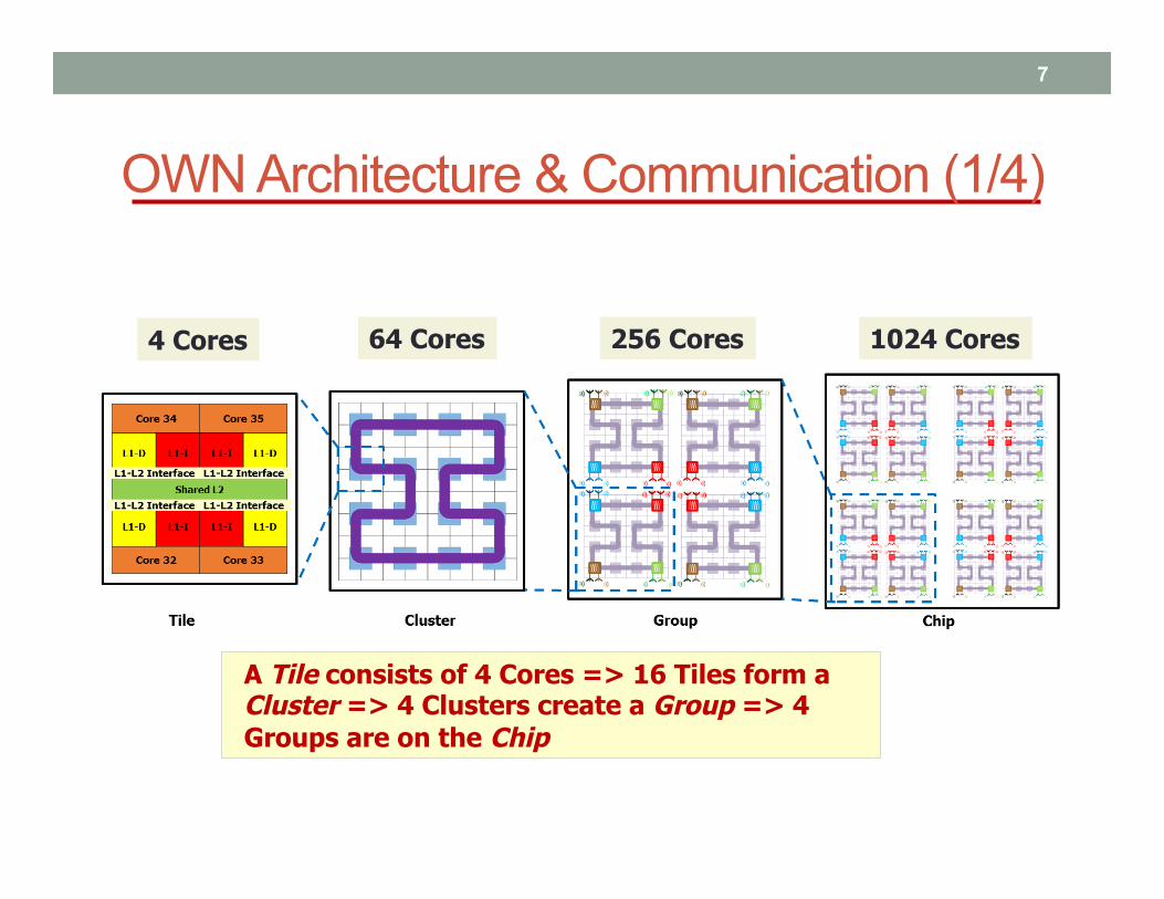
A Tile consists of 4 Cores => 16 Tiles form a Cluster => 4 Clusters create a Group => 4 Groups are on the Chip
4 Cores 64 Cores 1024 Cores 256 Cores
OWN Architecture & Communication (1/4)
7

OWN Architecture & Communication (2/4)
8
Inactive Modulators
Active Modulators
De- modulators
Cluster & Intra-cluster optical communication
Waveguide
Arbitration Waveguide
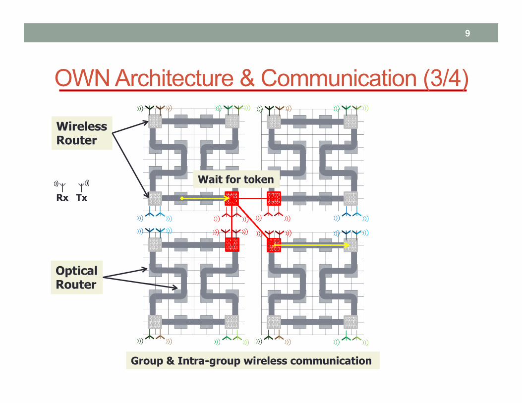
OWN Architecture & Communication (3/4)
9
Group & Intra-group wireless communication
Tx Rx
Optical Router
Wireless Router
Wait for token

OWN Architecture & Communication (4/4)
10
Chip & Inter-group wireless communication
I A
M E
A I
M E
K B
O F
B K
O F
M E
I A
M E
A I
O F
K B
O F
B K
J C
P G
C J
P G
L D
N H
D L
N H
P G
J C
P G
C J
N H
L D
N H
D L
G0 G1
G3
G2
Wait for token
Wait for token
Wait for token

OWN Deadlocks & Solution
11
C C
C C
D D
D D
G G
G G
H H
H H
L
L
L
L
J J
J J
N N
N N
P P
P P
Group 2 Group 3
Wireless Router
Cluster
Optical Link
Intra-group Wireless Link
Inter-group Wireless Link
Circular Dependency
Solution => VC allocation based on packet types which requires 4 VCs per port
Core Core
• VC0 = Intra-cluster & Intra-group • VC1 = Inter-group horizontal • VC2 = Inter-group vertical • VC3 = Inter-group diagonal
Input Output

– Architectures: OWN, Cmesh (wired only), Wcube (hybrid wireless) and ATAC (hybrid optical)
– Number of cores: 1024 – Synthetic Benchmarks: Uniform (UN), Bit-Reversal (BR),
Complement (COMP), Matrix Transpose (MT), Perfect Shuffle (PS), and Neighbor (NBR)
– Network Simulation: Optisim*
– Area and Power Analysis • Dsent# to calculate wire link and router area and power at bulk
45nm LVT • Optical link area and power (waveguide, micro-ring resonators,
laser power) • Wireless transceiver area is 0.62 mm2 and energy 1pJ/bit$
12
Performance Analysis
* A. Kodi and A. Louri, “A system simulation methodology of optical interconnects for high-performance computing systems,” J. Opt. Netw, vol. 6, no. 12, pp. 1282–1300, 2007 # C. Sun, C.-H. Chen, G. Kurian, L. Wei, J. Miller, A. Agarwal, L.-S. Peh, and V. Stojanovic, “Dsent-a tool connecting emerging photonics with electronics for opto-electronic networks-on-chip modeling,” in Networks on Chip (NoCS), 2012 Sixth IEEE/ACM International Symposium on. IEEE, 2012, pp. 201–210 $ D. DiTomaso, A. Kodi, D. Matolak, S. Kaya, S. Laha, and W. Rayess, “Energy-efficient adaptive wireless nocs architecture,” in Networks on Chip (NoCS), 2013 Seventh IEEE/ACM International Symposium on. IEEE, 2013, pp. 1–8.
13
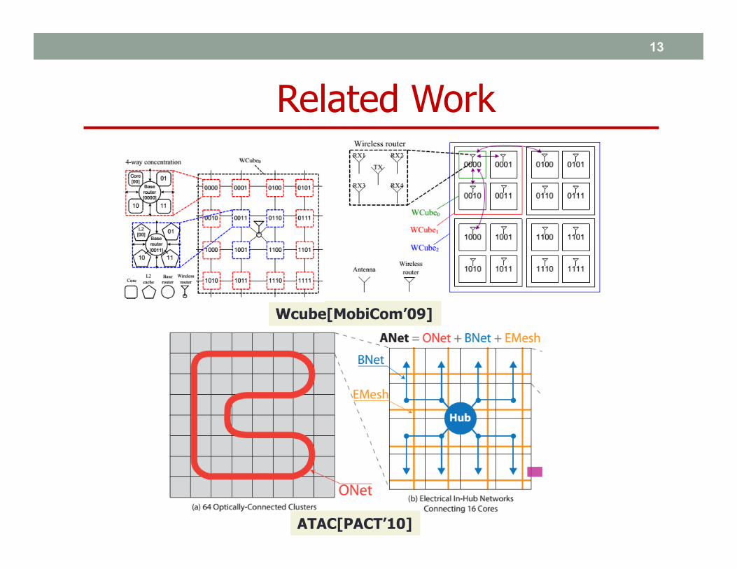
Related Work
Wcube[MobiCom’09]
ATAC[PACT’10]
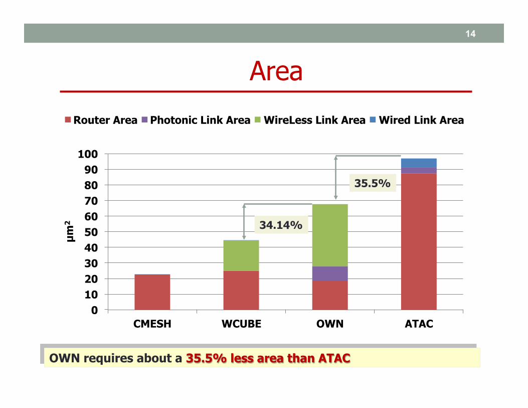
0 10 20 30 40 50 60 70 80 90
100
CMESH WCUBE OWN ATAC
µm
2
Router Area Photonic Link Area WireLess Link Area Wired Link Area
14
OWN requires about a 35.5% less area than ATAC
Area
35.5%
34.14%
15
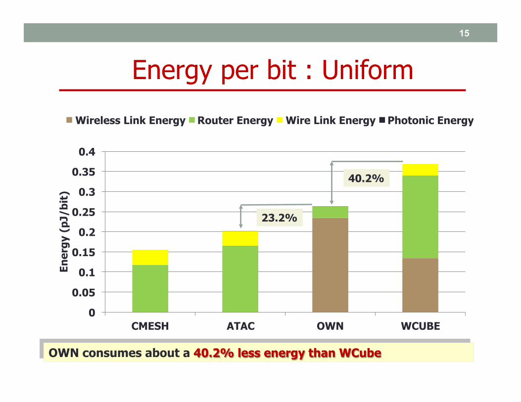
OWN consumes about a 40.2% less energy than WCube
Energy per bit : Uniform
0
0.05
0.1
0.15
0.2
0.25
0.3
0.35
0.4
CMESH ATAC OWN WCUBE
Ener
gy (
pJ/b
it)
Wireless Link Energy Router Energy Wire Link Energy Photonic Energy
40.2%
23.2%

0
0.05
0.1
0.15
0.2
0.25
0.3
CMESH ATAC OWN WCUBE
Ener
gy (
pJ/b
it)
Wireless Link Energy Router Energy Photonic Energy Wire Link Energy
16
OWN consumes about a 21.2% less energy than WCube
Energy per bit : Perfect Shuffle
21.2%
3%
17
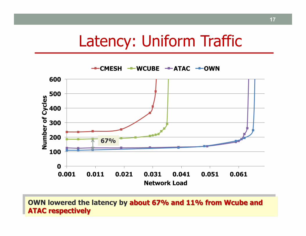
OWN lowered the latency by about 67% and 11% from Wcube and ATAC respectively
Latency: Uniform Traffic
0
100
200
300
400
500
600
0.001 0.011 0.021 0.031 0.041 0.051 0.061
Num
ber
of C
ycle
s
Network Load
CMESH WCUBE ATAC OWN
67%

18
OWN lowered the latency by about 69%, 57% and 11% from CMesh, Wcube and ATAC respectively
Latency: Bit-Reversal Traffic
0
100
200
300
400
500
600
0.001 0.026 0.051 0.076
Num
ber
of C
ycle
s
Network Load
CMESH WCUBE ATAC OWN
69%
57%

19
OWN outperforms WCube and Cmesh on average by about 8% and 28% respectively
Saturation Throughput
0
0.05
0.1
0.15
0.2
0.25
UN BR COMP MT PS NBR GM
Satu
rati
on T
hrou
ghpu
t (f
lits/
cycl
e/co
re)
CMESH WCUBE ATAC OWN

• OWN requires 35.5% less area than ATAC but 34.14% higher area than WCube
• OWN requires 30.36% less energy/bit than WCube but 13.99% higher energy/bit than ATAC
• OWN has higher saturation throughput & lower latency compared to wired, wireless and optical networks
• CMOS technology advancement will benefit OWN in both area and energy/bit
• Dynamic wireless channel allocation can be a future work
20
Conclusions & Future Work

Thank You
Questions?

Decomposed Crossbar Router
22
VC 1
VC 2
VC 3
VC 4
Input Buffers MUX
VC 1
VC 2
VC 3
VC 4
Input Buffers MUX
VC 1
VC 2
VC 3
VC 4
Input Buffers MUX
Route Computation
VC Allocator
Switch Allocator
Input 1
Output 1
Output 3
Output 2
Output 4
Input 4
Input 1
Output Unit
Crossbar Switch
Output 1
Output 15 Output
Unit
To Cores
From Cores

• Laser Power (one wavelength) = Longest Link x 1dB/cm + 1 dB (for modulation) + 1dB (for demodulation) + 0.0001 x ring modulator adjacent + 0.2dB (splitter) + 1dB (photodetector loss)
• Laser Efficiency = 15% • Receiver Sensitivity = -17dBm • Pin = 10 ^ (loss in dB / 10) x Pout • Ptotal = #WL (Pin / Laser Eff.) + (Pin / Laser Eff.) x
Arbitration Link • Ring Heating Power = 26uW/ring • Ring Modulating = 500uW/ring
23
Optical Power Calculation
• Ring Resonator diameter 12um • WG = Width (4um) x Length
24
Optical Area Calculation