Embed Size (px)
Citation preview

www.ublox.com
UBX-15021499 - R20
OWL253 and OWS451Wi-Fi SPI and UART modulesElectrical Mechanical Data Sheet
Abstract
This document describes the electrical and mechanical data of the IEEE 802.11
a/b/g/n OEM Modules developed for integration in industrial devices.

OWL253 and OWS451 - Electrical Mechanical Data Sheet
UBX-15021499 - R20 Production Information Page of 2 54
Document InformationTitle OWL253 and OWS451Subtitle Wi-Fi SPI and UART modulesDocument type Electrical Mechanical Data SheetDocument number UBX-15021499Revision and date R20 29-Nov-2016Document status Production Information
u-blox reserves all rights to this document and the information contained herein. Products, names, logos and designs described
herein may in whole or in part be subject to intellectual property rights. Reproduction, use, modification or disclosure to third
parties of this document or any part thereof without the express permission of u-blox is strictly prohibited.
The information contained herein is provided “as is” and u-blox assumes no liability for the use of the information. No
warranty, either express or implied, is given, including but not limited, with respect to the accuracy, correctness, reliability and
fitness for a particular purpose of the information. This document may be revised by u-blox at any time. For most recent
documents, visit . Copyright © 2016, u-blox AG.www.u-blox.com
u-blox® is a registered trademark of u-blox Holding AG in the EU and other countries. ARM® is the registered trademark of
ARM Limited in the EU and other countries.

OWL253 and OWS451 - Electrical Mechanical Data Sheet
UBX-15021499 - R20 Production Information Page of 3 54
Contents
1 Introduction . . . . . . . . . . . . . . . . . . . . . . . . . . . . . . . . . . . . . . . . . . . . . . . . . . . . . 51.1 Key features . . . . . . . . . . . . . . . . . . . . . . . . . . . . . . . . . . . . . . . . . . . . . . . . . . . . . . . . . . . . . . . . . 5
1.2 Product variants . . . . . . . . . . . . . . . . . . . . . . . . . . . . . . . . . . . . . . . . . . . . . . . . . . . . . . . . . . . . . . 6
1.3 Block diagram cB-0941 . . . . . . . . . . . . . . . . . . . . . . . . . . . . . . . . . . . . . . . . . . . . . . . . . . . . . . . . 7
1.3.1 OWS451 . . . . . . . . . . . . . . . . . . . . . . . . . . . . . . . . . . . . . . . . . . . . . . . . . . . . . . . . . . . . . . . . . . . 7
1.3.2 OWL253 . . . . . . . . . . . . . . . . . . . . . . . . . . . . . . . . . . . . . . . . . . . . . . . . . . . . . . . . . . . . . . . . . . . 8
2 Electrical interface and connectors . . . . . . . . . . . . . . . . . . . . . . . . . . . . . . . . . . . 82.1 Pin numbering . . . . . . . . . . . . . . . . . . . . . . . . . . . . . . . . . . . . . . . . . . . . . . . . . . . . . . . . . . . . . . . 9
2.1.1 Primary side connectors . . . . . . . . . . . . . . . . . . . . . . . . . . . . . . . . . . . . . . . . . . . . . . . . . . . . . . 9
2.1.2 Secondary side connectors . . . . . . . . . . . . . . . . . . . . . . . . . . . . . . . . . . . . . . . . . . . . . . . . . . . . 9
2.2 Pin description . . . . . . . . . . . . . . . . . . . . . . . . . . . . . . . . . . . . . . . . . . . . . . . . . . . . . . . . . . . . . . 10
2.2.1 J2, J3, J6, J8 connector description . . . . . . . . . . . . . . . . . . . . . . . . . . . . . . . . . . . . . . . . . . . . 10
2.2.2 J4 Primary external antenna connector . . . . . . . . . . . . . . . . . . . . . . . . . . . . . . . . . . . . . . . . 11
2.2.3 J5 Auxiliary external antenna connector . . . . . . . . . . . . . . . . . . . . . . . . . . . . . . . . . . . . . . . 11
2.3 Electrical characteristics . . . . . . . . . . . . . . . . . . . . . . . . . . . . . . . . . . . . . . . . . . . . . . . . . . . . . . . 12
2.3.1 Power supply . . . . . . . . . . . . . . . . . . . . . . . . . . . . . . . . . . . . . . . . . . . . . . . . . . . . . . . . . . . . . . 12
2.3.2 I/O DC characteristics . . . . . . . . . . . . . . . . . . . . . . . . . . . . . . . . . . . . . . . . . . . . . . . . . . . . . . . 13
2.3.3 UART (OWS451) . . . . . . . . . . . . . . . . . . . . . . . . . . . . . . . . . . . . . . . . . . . . . . . . . . . . . . . . . . . 14
2.3.4 SPI (OWL253) . . . . . . . . . . . . . . . . . . . . . . . . . . . . . . . . . . . . . . . . . . . . . . . . . . . . . . . . . . . . . . 14
2.4 Environmental characteristics . . . . . . . . . . . . . . . . . . . . . . . . . . . . . . . . . . . . . . . . . . . . . . . . . . 17
2.5 Mechanical characteristics . . . . . . . . . . . . . . . . . . . . . . . . . . . . . . . . . . . . . . . . . . . . . . . . . . . . . 18
2.6 Hardware reset . . . . . . . . . . . . . . . . . . . . . . . . . . . . . . . . . . . . . . . . . . . . . . . . . . . . . . . . . . . . . 18
2.7 Power control . . . . . . . . . . . . . . . . . . . . . . . . . . . . . . . . . . . . . . . . . . . . . . . . . . . . . . . . . . . . . . . 18
2.8 Software overview . . . . . . . . . . . . . . . . . . . . . . . . . . . . . . . . . . . . . . . . . . . . . . . . . . . . . . . . . . . 18
2.8.1 cB-0941 (OWL253) . . . . . . . . . . . . . . . . . . . . . . . . . . . . . . . . . . . . . . . . . . . . . . . . . . . . . . . . . . 18
2.8.2 cB-0941 (OWS451) . . . . . . . . . . . . . . . . . . . . . . . . . . . . . . . . . . . . . . . . . . . . . . . . . . . . . . . . . . 19
3 Antenna information . . . . . . . . . . . . . . . . . . . . . . . . . . . . . . . . . . . . . . . . . . . . . 203.1 Caution . . . . . . . . . . . . . . . . . . . . . . . . . . . . . . . . . . . . . . . . . . . . . . . . . . . . . . . . . . . . . . . . . . . . 20
3.2 Surface mounted antenna (internal) . . . . . . . . . . . . . . . . . . . . . . . . . . . . . . . . . . . . . . . . . . . . 21
3.2.1 Radiation patterns . . . . . . . . . . . . . . . . . . . . . . . . . . . . . . . . . . . . . . . . . . . . . . . . . . . . . . . . . 21
3.3 External antennas . . . . . . . . . . . . . . . . . . . . . . . . . . . . . . . . . . . . . . . . . . . . . . . . . . . . . . . . . . . 23
3.4 Antenna accessories . . . . . . . . . . . . . . . . . . . . . . . . . . . . . . . . . . . . . . . . . . . . . . . . . . . . . . . . . . 24
3.5 Antennas . . . . . . . . . . . . . . . . . . . . . . . . . . . . . . . . . . . . . . . . . . . . . . . . . . . . . . . . . . . . . . . . . . 25
3.5.1 Recommended antennas . . . . . . . . . . . . . . . . . . . . . . . . . . . . . . . . . . . . . . . . . . . . . . . . . . . . 25
3.5.2 Alternative antennas . . . . . . . . . . . . . . . . . . . . . . . . . . . . . . . . . . . . . . . . . . . . . . . . . . . . . . . 29
3.5.3 Customer specific antennas . . . . . . . . . . . . . . . . . . . . . . . . . . . . . . . . . . . . . . . . . . . . . . . . . . 35
4 Mounting information . . . . . . . . . . . . . . . . . . . . . . . . . . . . . . . . . . . . . . . . . . . . 36

OWL253 and OWS451 - Electrical Mechanical Data Sheet
UBX-15021499 - R20 Production Information Page of 4 54
4.1 Module dimensions . . . . . . . . . . . . . . . . . . . . . . . . . . . . . . . . . . . . . . . . . . . . . . . . . . . . . . . . . . 36
4.1.1 Mounting holes . . . . . . . . . . . . . . . . . . . . . . . . . . . . . . . . . . . . . . . . . . . . . . . . . . . . . . . . . . . . 38
4.2 Using the J2/J3 board-to-board connectors . . . . . . . . . . . . . . . . . . . . . . . . . . . . . . . . . . . . . . . 38
4.2.1 Single row connectors . . . . . . . . . . . . . . . . . . . . . . . . . . . . . . . . . . . . . . . . . . . . . . . . . . . . . . 38
4.2.2 Double row ASP-118580-01 connector . . . . . . . . . . . . . . . . . . . . . . . . . . . . . . . . . . . . . . . . . 40
4.3 Using press-fit nuts for mounting the module . . . . . . . . . . . . . . . . . . . . . . . . . . . . . . . . . . . . 41
4.4 Recommended M2 screw . . . . . . . . . . . . . . . . . . . . . . . . . . . . . . . . . . . . . . . . . . . . . . . . . . . . . 41
4.5 Using the J6 PCB solder pads . . . . . . . . . . . . . . . . . . . . . . . . . . . . . . . . . . . . . . . . . . . . . . . . . . 42
4.5.1 Host board . . . . . . . . . . . . . . . . . . . . . . . . . . . . . . . . . . . . . . . . . . . . . . . . . . . . . . . . . . . . . . . . 42
4.5.2 Mounting process . . . . . . . . . . . . . . . . . . . . . . . . . . . . . . . . . . . . . . . . . . . . . . . . . . . . . . . . . . 42
4.6 Antenna issues . . . . . . . . . . . . . . . . . . . . . . . . . . . . . . . . . . . . . . . . . . . . . . . . . . . . . . . . . . . . . . 43
5 Wireless LAN information . . . . . . . . . . . . . . . . . . . . . . . . . . . . . . . . . . . . . . . . . 445.1 Radio sensitivity OFDM . . . . . . . . . . . . . . . . . . . . . . . . . . . . . . . . . . . . . . . . . . . . . . . . . . . . . . . 44
5.2 Radio sensitivity DSSS . . . . . . . . . . . . . . . . . . . . . . . . . . . . . . . . . . . . . . . . . . . . . . . . . . . . . . . . 45
6 Regulatory information . . . . . . . . . . . . . . . . . . . . . . . . . . . . . . . . . . . . . . . . . . . 456.1 European Union Regulatory Compliance . . . . . . . . . . . . . . . . . . . . . . . . . . . . . . . . . . . . . . . . . 45
6.1.1 Declaration of conformity . . . . . . . . . . . . . . . . . . . . . . . . . . . . . . . . . . . . . . . . . . . . . . . . . . . 45
6.1.2 Equipment classes . . . . . . . . . . . . . . . . . . . . . . . . . . . . . . . . . . . . . . . . . . . . . . . . . . . . . . . . . . 46
6.2 IC and FCC compliance . . . . . . . . . . . . . . . . . . . . . . . . . . . . . . . . . . . . . . . . . . . . . . . . . . . . . . . 47
6.2.1 IC compliance . . . . . . . . . . . . . . . . . . . . . . . . . . . . . . . . . . . . . . . . . . . . . . . . . . . . . . . . . . . . . 47
6.2.2 Conformité aux normes d’IC . . . . . . . . . . . . . . . . . . . . . . . . . . . . . . . . . . . . . . . . . . . . . . . . . 47
6.2.3 FCC statement . . . . . . . . . . . . . . . . . . . . . . . . . . . . . . . . . . . . . . . . . . . . . . . . . . . . . . . . . . . . . 48
6.3 Japan Radio Equipment Compliance (TELEC) . . . . . . . . . . . . . . . . . . . . . . . . . . . . . . . . . . . . . 50
6.4 UL listing information . . . . . . . . . . . . . . . . . . . . . . . . . . . . . . . . . . . . . . . . . . . . . . . . . . . . . . . . 51
6.5 Compliance with RoHS directive . . . . . . . . . . . . . . . . . . . . . . . . . . . . . . . . . . . . . . . . . . . . . . . . 51
7 Guidelines for efficient and safe use . . . . . . . . . . . . . . . . . . . . . . . . . . . . . . . . 527.1 General . . . . . . . . . . . . . . . . . . . . . . . . . . . . . . . . . . . . . . . . . . . . . . . . . . . . . . . . . . . . . . . . . . . . 52
7.2 Product care . . . . . . . . . . . . . . . . . . . . . . . . . . . . . . . . . . . . . . . . . . . . . . . . . . . . . . . . . . . . . . . . 52
7.3 Radio frequency exposure . . . . . . . . . . . . . . . . . . . . . . . . . . . . . . . . . . . . . . . . . . . . . . . . . . . . . 52
7.4 Electronic equipment . . . . . . . . . . . . . . . . . . . . . . . . . . . . . . . . . . . . . . . . . . . . . . . . . . . . . . . . 53
7.5 Potentially explosive atmospheres . . . . . . . . . . . . . . . . . . . . . . . . . . . . . . . . . . . . . . . . . . . . . . 53
7.6 Safety compliance . . . . . . . . . . . . . . . . . . . . . . . . . . . . . . . . . . . . . . . . . . . . . . . . . . . . . . . . . . . 53

OWL253 and OWS451 - Electrical Mechanical Data Sheet
UBX-15021499 - R20 Production Information Page of 5 54
1 IntroductionThe IEEE 802.11a,b,g,n OEM Modules from u-blox has been developed for integration in industrial devices. The modules are providing state of the art low power features, compatibility, robustness, and reliability. The modules minimizes the work needed to implement IEEE 802.11 in a device as it provides, together with the driver package, all software, hardware, type approval, EMC certification etc. It is developed for reliable, high demanding industrial devices and applications and delivers high performance. The u-blox wireless LAN modules are available in different versions (see Product variants).
The wireless LAN modules are complete IEEE 802.11 implementations. The IEEE 802.11 modules has small form factors and the interface layout is the same as the Bluetooth and IEEE 802.15.4 modules from u-blox, which enables customers to prepare their device for both wireless LAN, IEEE 802.15.4, and Bluetooth.
cB-0941 (OWS451i-06) cB-0941 (OWL253i-04)
This electrical & mechanical data sheet is applicable to the following wireless LAN modules from u-blox:
cB-0941 (OWS451 and OWL253)
1.1 Key features
Dual-band operation (IEEE 802.11-2007, a,b,g, incl. single stream IEEE 802.11n)
WEP, AES, and CRC-32 hardware accelerators
WPA and WPA2 support - both personal and enterprise modes
LEAP support
PEAP support
EAP-TLS support (OWS451)
High speed UART host interface (OWS451)
SPI host interface (OWL253)
Quality of Service: 802.11e and WMM
Bluetooth co-location with PTA (Packet Traffic Arbitration) support

OWL253 and OWS451 - Electrical Mechanical Data Sheet
UBX-15021499 - R20 Production Information Page of 6 54
Ad-hoc and infrastructure mode
Radio type approved for Europe
Unlicensed Modular Transmitter Approval for US (FCC) and Canada (IC)
Radio type approved for Japan (2.4 GHz band only)
Compliant with EMC standards.
Industrial operating temperature range -40 to +85 °C (JST version limited to -25 to +85°C)
Support for low power modes.
Compatible with u-blox Bluetooth and IEEE 802.15.4 modules
Internal or external U.FL. antenna connectors
Receive diversity
1.2 Product variants
The different mounting options of cB-0941 hardware (OWS451i/x -04/06 and OWL253i/x-04) are all based on the same PCB.The module is Type Approved and referred in this document with the model name cB-0941.
Product name
Regulatory IDFCC IDIC IDMIC ID
Description
OWL253i-04
cB-0941PVH09415325A-0941204-310004
IEEE802.11a,b,g,n LAN module with internal antenna, board-to-board connector, solder-lands, high-speed SPI host interface
OWL253x-04
cB-0941PVH09415325A-0941204-310004
IEEE802.11a,b,g,n LAN module with dual external antenna U.FL. connectors, board-to-board connector, solder-lands, high-speed SPI host interface
OWS451i-04
cB-0941PVH09415325A-0941204-310005
IEEE802.11a,b,g,n Serial Port Adapter module with internal antenna, board-to-board connector, solder-lands, UART host interface
OWS451x-04
cB-0941PVH09415325A-0941204-310005
IEEE802.11a,b,g,n Serial Port Adapter module with dual external antenna U.FL. connectors, board-to-board connector, solder-lands, UART host interface
OWL253 and OWS451 - Electrical Mechanical Data Sheet
UBX-15021499 - R20 Production Information Page of 7 54
Product name
Regulatory IDFCC IDIC IDMIC ID
Description
OWS451i-06
cB-0941PVH09415325A-0941204-310005
IEEE802.11a,b,g,n Serial Port Adapter module with internal antenna, board-to-board connector, solder-lands, JST connector, UART host interface
OWS451x-06
cB-0941PVH09415325A-0941204-310005
IEEE802.11a,b,g,n Serial Port Adapter module with dual external antenna U.FL. connectors, board-to-board connector, solder-lands, JST connector, UART host interface
1.3 Block diagram cB-0941
1.3.1 OWS451

OWL253 and OWS451 - Electrical Mechanical Data Sheet
UBX-15021499 - R20 Production Information Page of 8 54
1.3.2 OWL253
2 Electrical interface and connectorsThis section describes the signals available on the module interface connectors. There are three ways of connecting:
Via J6, PCB solder lands on the edge of the PCB. For more information see sections 3.2 and 5.5.(see the figure in section 3.1.2 Secondary side connectors).
Via connectors J2 and J3, 20 x 2-pin 1mm pitch board-to-board (one piece part).The J2 and J3 connectors exist on the module only as compression pads.(see the figure in section 3.1.2 Secondary side connectors).These pads mates with the carrier board one-piece part connector.For more information see section 3.2 and 5.2.
Optional (OWS451 only):
Via J8, JST connector (see the figure in section 3.1.1 Primary side connectors).The connector is a 6 x 1 shrouded pin header, 1 mm pitch.The JST part number is SM06B-SRSS-TB and the mating part is wire connector SHR-06V-S.Other connector options are also available from JST.For more information see section J8 Connector Description.
The JST connector affects temperature range. See environmental characteristics for Note:details.

OWL253 and OWS451 - Electrical Mechanical Data Sheet
UBX-15021499 - R20 Production Information Page of 9 54
2.1 Pin numbering
2.1.1 Primary side connectors
J8 is the JST connector located on the primary side of the module. A1 is the internal antenna.J4 and J5 are U.FL connectors for external antennas. J4 is the primary antenna connector and J5 the auxiliary antenna connector.
2.1.2 Secondary side connectors
J2 and J3 is the u-blox board-to-board one piece part connector. The pin layout of the connector is compatible with all OEM Serial Port Adapters from u-blox. J6 designates the solder land connector.
The solder lands of connector (J6) have a new layout compared to cB-OWSPA311g.

OWL253 and OWS451 - Electrical Mechanical Data Sheet
UBX-15021499 - R20 Production Information Page of 10 54
2.2 Pin description
2.2.1 J2, J3, J6, J8 connector description
J2 J3 J6 J8 Signalname
Signal level
Type Module Description
1,2 8 3,25(1)
1 VSS Ground Power All GND
3,4 - 4 2 VDD 3.3 V Power All 3.3 - 5.5 VDC power supply
11 - 7 - RED/Mode CMOS/Weakpull-up
Out/In OWS451 This signal is multiplexed:RED: red LED logic signal valid 600ms after power-up, active low with internal weak pull-up.
Mode: Not used, available on u-blox products with internal RS232 transceiver to select logic level mode (disable RS232).Check the data sheet for these products to remain compatible.
12 - 6 - Switch-0 CMOS/Weakpull-up
In OWS451 Switch-0/Function switch. Used by the "Connect on external event" function, see the Wireless LAN Serial Port Adapter AT command Specification for more information.
Secondary function: If switch-0 and switch-1 is active (LOW) at power-up the module will enter boot loader mode.
13 - 8 - GREEN/Switch-1
CMOS/Weakpull-up
Out/In OWS451 This signal is multiplexed:GREEN: green-LED signal valid 500ms after power-up, active low.
Switch-1/restore switch: Switch-1 signal is valid as input only during the first 500ms during power-up, after that its function changes to green LED.If this pin is active (LOW) during power-up the unit restores all settings to factory defaults.
14 - 9 - BLUE CMOS Out OWS451 Logic Blue LED Signal (see the Operating status section). Active low.Note:Blue LED will flash when data is transferred.
15 - 10 5 UART-CTS CMOS In OWS451 UART Clear To Send, active low.
16 - 11 3 UART-TxD CMOS Out OWS451 UART Transmit Data, "0" = Low, "1" = High
17 - 12 6 UART-RTS CMOS Out OWS451 UART Request To Send, active low.
18 - 13 4 UART-RxD CMOS In OWS451 UART Receive Data, "0" = Low, "1" = High
19 - 5 - UART-DTR CMOS Out OWS451 UART Data Terminal Ready, active low.
20 - 18,30(1)
- UART-DSR CMOS In OWS451 UART Data Set Ready, active low.
- 6 28 - SPI-CS0n CMOS In OWL253 SPI chip select, active low.
- 7 27 - SPI-MOSI CMOS In OWL253 SPI Master Output Slave Input
- 9 36 - SerialSelect-0
CMOS Out OWS451 Control signal for external serial transceivers.See Appendix Serial Interface section for more info.
- 10 35 - SerialSelect-1
CMOS Out OWS451 Control signal for external serial transceivers.See Appendix Serial Interface section for more info.
- 11 26 - SPI-CLK CMOS In OWL253 SPI Clk input

OWL253 and OWS451 - Electrical Mechanical Data Sheet
UBX-15021499 - R20 Production Information Page of 11 54
J2 J3 J6 J8 Signalname
Signal level
Type Module Description
- 13 24 - SPI-MISO CMOS Out OWL253 SPI Master Input Slave Output
- 14 23 - SPI-Int CMOS Out OWL253 SPI external interrupt.
- 15 14 - PRI CMOS In All Bluetooth Priority arbitration signal. This pin indicates to a wireless LAN module that a Bluetooth module is, or will be, active to do high priority TX/RX. Wireless LAN does not transmit as long as this signal remains asserted. The pin should be left open when Bluetooth co-existence feature is not enabled.
- 17 15 - WL CMOS Out All Wireless LAN Active arbitration signal. This pin indicates to a Bluetooth module that a wireless LAN module is, or will be, active to do TX/RX. When Bluetooth co-existence feature is not enabled this pin should be left open.
- 19 1 - Reset-n CMOS In All Hardware reset. Active low.internal 270k ohm pull-up
- 20 2 - 3V3 3.3 V Out All Regulated output to supply voltage level shifting interface,max load10mA.
5-10
1-5,12,16,18
16,17;19-21,29,31-34
- Reserved, do not connect.
(1) Alternative signal pin recommended to use in new designs (both signal pins should be connected).CMOS signals characteristics: - 0.3 V < V < 0.8 V, 2 V < V < 3.6 V, V < 0.4 V, V > 2.4 VIL IH OL OH
2.2.2 J4 Primary external antenna connector
J4 is the primary external antenna connector. It is used for both transmit and receive. The port impedance to match is 50 ohm.
J4 pin nr Pin name Signal level Type Description
1 Ant-1 RF I/O Primary external antenna port (50 ohm)
This connector is only available on OWS451x and OWL253x.
2.2.3 J5 Auxiliary external antenna connector
J5 is the auxiliary external antenna connector. It is used only for receiving and if the unit is configured for receive diversity mode. The unit never transmits RF through this antenna connector. The port impedance to match is 50 ohm.
J5 pin nr Pin name Signal level Type Description
1 Ant-1 RF I Auxiliary external antenna port (50 ohm)
This connector is only available on OWS451x and OWL253x.

OWL253 and OWS451 - Electrical Mechanical Data Sheet
UBX-15021499 - R20 Production Information Page of 12 54
2.3 Electrical characteristics
The cB-0941 family is designed to be fully interchangeable with the u-blox Bluetooth product range. If the host product has space for the board, it is possible to choose freely between Bluetooth modules, e.g. cB-OEMSPA311i/x or cB-OEMSPA331i/x, or Wireless LAN modules, e.g. OWSPA311gi/x, without any change of the host product. If you design your power supply for OWS451i/x the modules will be fully interchangeable.
2.3.1 Power supply
Read the safety notes in section Guidelines for Efficient and Safe Use before using the modules.
Supply voltage
Symbol Parameter Min Typ. Max Unit
VDD Supply voltage 3.3 5.5 V
Current consumption
OWS451 (VDD = 3.3 V)
Symbol Power Mode State Band DTIM Min Typ. Max Unit
IDD Global Reset 16 mA
Start-up 130 150 mA
Peak 350 mA
Sleep Idle, no connection 22 mA
Managed, connected 2.4GHz 1 34 mA
Managed, connected 5GHz 1 29 mA
Managed, connected 2.4GHz 5 29 mA
Managed, connected 5GHz 5 25 mA
Managed, data throughput 1 Mbit/s 2.4GHz 180 mA
Managed, data throughput 1 Mbit/s 5GHz 222 mA
Online Idle, no connection 22 mA
Managed, connected 2.4GHz 1 180 mA
Managed, connected 5GHz 1 222 mA

OWL253 and OWS451 - Electrical Mechanical Data Sheet
UBX-15021499 - R20 Production Information Page of 13 54
Symbol Power Mode State Band DTIM Min Typ. Max Unit
Managed, connected 2.4GHz 5 180 mA
Managed, connected 5GHz 5 220 mA
Managed, data throughput 1 Mbit/s 2.4GHz 180 mA
Managed, data throughput 1 Mbit/s 5GHz 222 mA
Stop Idle, no connection 9 mA
Managed, connected 2.4GHz 1 34 mA
Managed, connected 5GHz 1 18 mA
Managed, connected 2.4GHz 5 26 mA
Managed, connected 5GHz 5 14 mA
Managed, data throughput UART 1 Mbit/s 2.4GHz 180 mA
Managed, data throughput UART 1 Mbit/s 5GHz 222 mA
Ad-Hoc Connected 2.4GHz - 180 mA
Data throughput 1Mbit/s 2.4GHz - 180 mA
Power consumption in sleep, online, and stop mode are measured in managed mode using firmware release 2.17.13310.
OWL253 (VDD = 3.3 V)
Symbol Power Mode State Band DTIM Min Typ. Max Unit
IDD Global Reset 16 mA
Start-up 130 150 mA
Peak 350 mA
Power save Idle, no connection 11 mA
Managed, connected 2.4GHz 1 20 mA
Managed, connected 5.0GHz 1 20 mA
Managed, data throughput UDP 1Mbit/s 2.4GHz 1 230 mA
Managed, data throughput UDP 1Mbit/s 5.0GHz 1 240 mA
Power consumption in power save mode (standard IEEE802.11 power save) is measured using firmware release 2.10.1. was used for throughput measurements. Configuration: iperf -IPerfc 192.168.0.1 -u -b 1M
2.3.2 I/O DC characteristics

OWL253 and OWS451 - Electrical Mechanical Data Sheet
UBX-15021499 - R20 Production Information Page of 14 54
2.3.2 I/O DC characteristics
Symbol Parameter Min Typ Max Unit
VIL LOW level input voltage -0.3 0.8 V
VIH HIGH level input voltage 2 3.6 V
VOL LOW level output voltage 0.4 V
VOH HIGH level output voltage 2.4 V
I GPIO Sink and source current 4.0 mA
C GPIO Input capacitance 8 pF
2.3.3 UART (OWS451)
Parameter Values
Standard baud rates 1200, 2400, 4800, 9600, 19200, 38400, 57600, 115200, 230400, 460800, 921600
High speed baud rates 1382400, 2764800
Data bits 8
Stop bits 1 or 2
Parity none, odd, even
Hardware flow control off or CTS/RTS
2.3.4 SPI (OWL253)
The SPI master should use polarity falling to rising with phase sampling on rising edge, shift on falling edge. Bit order is MSB to LSB.
The SPI slave has the possibility to use both normal SPI mode, with shift and sample on rising and falling edges respectively, and an enhanced high speed mode where the shift and sample are both done on the rising edge. Since this moves the shift half a SPI cycle forward, the clock frequency can approximately be increased by a factor of two given that the signal path can handle this.
Using the high speed mode does not change the setup for the master.
In order to determine the SPI clock frequency that can be used, the signal propagation delay also need to be taken into consideration. These propagation delays has to be measured for each individual setup. The clock frequency can then be approximated according to the following formulas.
Tclk = (Tod + Tprop + Tfall) * 2 Tclk_high = Tod + Tprop + Trise
Values measured on u-blox development board cb-0940-02 with a Cheetah SPI master in room temperature can be seen in table below.

OWL253 and OWS451 - Electrical Mechanical Data Sheet
UBX-15021499 - R20 Production Information Page of 15 54
Parameter Symbol Typ. Units
SPI_CLK, Clock rise time Trise 4.0 ns
SPI_CLK, Clock fall time Tfall 4.0 ns
SPI_MISO, MISO propagation delay Tprop 4.0 ns
SPI_CLK, Max clock freq. normal mode Fmax 40.0 MHz
SPI_CLK, Max clock freq. high speed mode Fhigh_max 50.0 (limited by Cheetah) MHz
SPI_CLK, Max clock freq. high speed mode Fhigh_max 75.0 (theoretical) MHz
Note that the measured F is very close to the limit of what is possible with respect to electrical maxproperties and propagation delays on this particular setup and there is a significant risk for bit errors. A reasonable limit using the above formula with the T from the chip specification below gives F od maxas follows:
Tclk = (Tod_max + Tprop + Tfall) * 2 = (9.0 + 4.0 + 4.0) * 2 => Fmax = ~29.4 MHz Tclk_high = Tod_max + Tprop + Trise = 9.5 + 4.0 + 4.0 => Fmax = ~57.1 MHz
SPI chip specifications - Normal mode
Parameter Symbol Min Max Units
SPI_CLK Tspi 0 25 MHz
SPI_CS, to output valid Tcs 3.5 7.5 ns
SPI_CS, input setup time Tcst 5.5 ns
SPI_MOSI, input setup time Tsd 1 ns
SPI_MOSI, input hold time Thd 1.5 ns
SPI_MISO, clock to output valid Tod 4 9 ns

OWL253 and OWS451 - Electrical Mechanical Data Sheet
UBX-15021499 - R20 Production Information Page of 16 54
SPI chip specifications - High speed mode
Parameter Symbol Min Max Units
SPI_CLK Tspi 25 75 MHz
SPI_CS, to output valid Tcs 3.5 7.5 ns
SPI_CS, input setup time Tcst 5.5 ns
SPI_MOSI, input setup time Tsd 1 ns
SPI_MOSI, hold time Thd 1.5 ns
SPI_MISO, clock to output valid Tod 4 9.5 ns

OWL253 and OWS451 - Electrical Mechanical Data Sheet
UBX-15021499 - R20 Production Information Page of 17 54
2.4 Environmental characteristics
Parameter Product variant Min Typ Max Unit
Storage temperature OWL253 -40 +125 °C
OWS451i-04OWS451x-04
-40 +125 °C
OWS451i-06OWS451x-06
-25 +85 °C
Operating temperature OWL253 -40 +85 °C
OWS451i-04OWS451x-04
-40 +85 °C
OWS451i-06OWS451x-06
-25 +85 °C
When OWS451 is equipped with J8 (JST connector) the temperature range is reduced to -25 to +85 °C.

OWL253 and OWS451 - Electrical Mechanical Data Sheet
UBX-15021499 - R20 Production Information Page of 18 54
2.5 Mechanical characteristics
Parameter Product variant Value Unit
Weight cB-OWL253-04 Typ 3.5 g
cB-OWS451-04 Typ 3.5 g
cB-OWS451-06 Typ 3.8 g
Dimension cB-OWL253-04 Typ 36 x 23 x 3.1 mm
cB-OWS451-04 Typ 36 x 23 x 3.1 mm
cB-OWS451-06 Typ 36 x 23 x 4.1 mm
2.6 Hardware reset
A hardware-reset input is available on J1 and J3 connectors. An external reset source must be open drain or collector. The RESET-n pin is pulled-up internally with 220 kOhm (OWL253) or 56 kOhm (OWS451).
2.7 Power control
The wireless LAN modules can be operated in several different power modes.
Standard IEEE802.11 power save
UAPSD/WMM Power Save Support
2.8 Software overview
2.8.1 cB-0941 (OWL253)
Wireless LAN driver for OWL253 consists of a host driver in binary format or source code, and target firmware in binary format. In the overview picture below these two software parts are represented by the yellow boxes.

OWL253 and OWS451 - Electrical Mechanical Data Sheet
UBX-15021499 - R20 Production Information Page of 19 54
1.
2.
3.
The host needs to be able to hold the target firmware since targets does not have on-board non-volatile memory. At startup, and at every reset or power cycle, the host driver will download firmware binaries to target before any wireless LAN operations can begin.
OS support
Software and drivers are available for the following operating systems:
Linux 2.6
WinCE 6.0
Embedded RTOS
Customized drivers for use in embedded systems are available upon request. Contact u-blox for more information.
2.8.2 cB-0941 (OWS451)
The OWS451 is a serial port adapter with an UART interface and fully embedded TCP/IP stack and driver. The module is presented as a serial port/UART to the host. Raw serial data is sent to the module, which will package the data into TCP/UDP packages and transmit via Wireless LAN.

OWL253 and OWS451 - Electrical Mechanical Data Sheet
UBX-15021499 - R20 Production Information Page of 20 54
3 Antenna informationThis chapter gives a quality overview of the different antenna options.
There are 2 different antenna options available:
An internal surface mounted (SMD) dual band antenna.
Two U.FL connectors for external antennas. Different types of external antennas are available.
3.1 Caution
This radio transmitter IC: 5325A-0941 cB-0941 has been approved by Industry Canada to operate with the antenna types listed below with the maximum permissible gain and required antenna impedance for each antenna type indicated. Antenna types not included in this list, having a gain greater than the maximum gain indicated for that type, are strictly prohibited for use with this device.
Cet émetteur radio IC: 5325A-0941 cB-0941 a été approuvé par Industry Canada pour fonctionner avec les types d’antenne énumérés ci-dessous avec le gain maximum autorisé et l’impédance nécessaire pour chaque type d’antenne indiqué. Les types d’antenne ne figurant pas dans cette liste et ayant un gain supérieur au gain maximum indiqué pour ce type-là sont strictement interdits d’utilisation avec cet appareil.

OWL253 and OWS451 - Electrical Mechanical Data Sheet
UBX-15021499 - R20 Production Information Page of 21 54
3.2 Surface mounted antenna (internal)
Part number cB-0941 (OWL253i / OWS451i)
Antenna FR05-S1-NO-1-004
Manufacturer Fractus
Gain 0 dBi @ 2.4GHz3 dBi @ 5GHz
avg. VSWR 3.1 @ 2.4GHz2.3 @ 5GHz
avg. Efficiency 22% @ 2.4GHz39% @ 5GHz
Antenna size (LxWxH) 7 x 3 x 2 mm
Comments The antenna gain is very dependent of the mounting of the module.The unit cannot be mounted in a metal-shielded enclosure with this antenna.
3.2.1 Radiation patterns

OWL253 and OWS451 - Electrical Mechanical Data Sheet
UBX-15021499 - R20 Production Information Page of 22 54
Radiation Pattern Cuts @2450 MHz – Free Space

OWL253 and OWS451 - Electrical Mechanical Data Sheet
UBX-15021499 - R20 Production Information Page of 23 54
Radiation Pattern Cuts @5400 MHz – Free Space
3.3 External antennas
The external antennas are connected to the module with the on board U.FL connectors. Some antennas are connected directly to the U.FL connector and some are connected via a U.FL to SMA (cB-ACC-18 or cB-ACC-48) or U.FL to reversed polarity SMA (cB-ACC-38) adapter cable.
The sections below lists the antennas that are included in the radio type approvals of the module. For each antenna the "Approvals" field defines in what country/region the antenna is allowed to use. Definitions of the "Approvals" field are:

OWL253 and OWS451 - Electrical Mechanical Data Sheet
UBX-15021499 - R20 Production Information Page of 24 54
FCC - The antenna is included in the FCC test reports, and thus approved for use in countries that accept the FCC radio approvals, primarily US.
IC - The antenna is included in the IC (Industrie Canada) test reports, and thus approved for use in countries that accept the IC radio approvals, primarily Canada.
R&TTE - The antenna is included in the R&TTE test reports, and thus approved for use in countries that accept the R&TTE radio approvals, primarily the European countries.
TELEC - The antenna is included in the Japanese government affiliated TELEC test reports, and thus approved for use in the Japanese market.
In general, antennas with Reverse Polarity SMA connector or U.FL connector are included in FCC, IC and R&TTE radio tests.Antennas with SMA connector are not allowed to be used in Canada and USA due to FCC/IC regulations but are in general included in R&TTE radio tests.
Antennas with a part number in the form "cB-ACC-XX" used to be available for orders via the connectBlue distribution network. Since the acquisition of connectBlue by u-blox antennas can not be ordered from u-blox. To order antennas please contact the manufacturer or the manufacturer distribution network.
For information about other antennas please contact u-blox.
3.4 Antenna accessories
Part Number cB-ACC-18 / cB-ACC-48
Name U.FL to SMA adapter cable
cB-ACC-18 manufacturer part number: K123249002cB-ACC-48 manufacturer part number: K1994/01
Manufacture/supplier cB-ACC-18: Stig WahlströmcB-ACC-48: IMS Connector Systems
Connector U.FL and SMA jack (outer thread and pin receptacle)
Cable length 120 mm
Cable loss Less than 0.5 dB
Comment The SMA connector can be mounted in a panel
Approval R&TTE, TELEC
Part Number cB-ACC-38
Name U.FL to Reverse Polarity SMA adapter cable
Manufacturer part number: K123743001

OWL253 and OWS451 - Electrical Mechanical Data Sheet
UBX-15021499 - R20 Production Information Page of 25 54
Part Number cB-ACC-38
Manufacture/supplier
Stig Wahlström
Connector U.FL and Reverse Polarity SMA jack (outer thread and pin)
Cable length 120 mm
Cable loss Less than 0.5 dB
Comment The Reverse Polarity SMA connector can be mounted in a panel
Approval FCC, IC, R&TTE, TELEC
3.5 Antennas
3.5.1 Recommended antennas
Part Number cB-ACC-53
Name Ex-IT WLAN RP-SMA(dual-band)
Manufacture ProAnt
Polarization Vertical
Gain / Imp. +3.0 dBi / 50ohm @ 2.4 GHz+3.0 dBi / 50ohm @ 5 GHz
Size Ø 10 x 107 mm
Connector Reverse Polarity SMA plug (inner thread and pin receptacle)
Comment To be used together with the U.FL to RP-SMA adapter cable (cB-ACC-38)
Approval FCC, IC, R&TTE, TELEC

OWL253 and OWS451 - Electrical Mechanical Data Sheet
UBX-15021499 - R20 Production Information Page of 26 54
Part Number cB-ACC-63
Name Ex-IT 2400-MHF 28-001
Manufacture ProAnt
Polarization Vertical
Gain / Imp. +2.0 dBi / 50ohm @ 2.4 GHz
Size Ø 12 x 28 mm
Cable length 100 mm
Connector U.FL
Comment To be connected to the U.FL connector on the PCB
Approval FCC, IC, R&TTE, TELEC
Part Number cB-ACC-61
Name Ex-IT 2400-RP-SMA 28-001
Manufacture ProAnt
Polarization Vertical
Gain / Imp. +2.0 dBi / 50ohm @ 2.4 GHz
Size Ø 12 x 28 mm
Connector Reverse Polarity SMA plug (inner thread and pin receptacle)
Comment To be used together with the U.FL to RP-SMA adapter cable (cB-ACC-38)
Approval FCC, IC, R&TTE, TELEC
Part Number cB-ACC-64
Name Ex-IT 2400-RP-SMA 70-002

OWL253 and OWS451 - Electrical Mechanical Data Sheet
UBX-15021499 - R20 Production Information Page of 27 54
Manufacture ProAnt
Polarization Vertical
Gain / Imp. +3.0 dBi / 50ohm @ 2.4 GHz
Size Ø 10 x 86 mm
Connector Reverse Polarity SMA plug (inner thread and pin receptacle)
Comment To be used together with the U.FL to RP-SMA adapter cable (cB-ACC-38)
Approval FCC, IC, R&TTE, TELEC
Part Number cB-ACC-60
Name Ex-IT 2400-MHF 70-001
Manufacture ProAnt
Polarization Vertical
Gain / Imp. +3.0 dBi / 50ohm @ 2.4 GHz
Size Ø 10 x 70 mm
Cable length 100 mm
Connector U.FL
Comment To be connected to the U.FL connector on the PCB
Approval FCC, IC, R&TTE, TELEC
Part Number cB-ACC-55
Name InSide WLAN(dual band)

OWL253 and OWS451 - Electrical Mechanical Data Sheet
UBX-15021499 - R20 Production Information Page of 28 54
Manufacture ProAnt
Polarization Vertical
Gain / Imp. +3.0 dBi / 50ohm @ 2.4 GHz+3.0 dBi / 50ohm @ 5 GHz
Size 27 x 12 mm (triangular)
Cable length 100 mm
Connector U.FL
Comment To be connected to the U.FL connector on the PCB
Approval FCC, IC, R&TTE, TELEC
Part Number cB-ACC-67
Name OutSide-2400
Manufacture ProAnt
Polarization Vertical
Gain / Imp. +3.0 dBi / 50ohm @ 2.4 GHz
Size 36 x 18 x 16 mm
Cable length 70 mm
Connector U.FL
Comment To be connected to the U.FL connector on the PCB
Approval FCC, IC, R&TTE, TELEC
Part Number cB-ACC-66
Name FlatWhip 2400

OWL253 and OWS451 - Electrical Mechanical Data Sheet
UBX-15021499 - R20 Production Information Page of 29 54
Part Number cB-ACC-66
Manufacture ProAnt
Gain / Imp. +3.0 dBi / 50ohm @ 2.4 GHz
Size Ø 50.0 x 30.0 mm
Connector SMA plug (inner thread and pin)
Comment To be used together with the U.FL to SMA adapter cable (cB-ACC-18 or cB-ACC-48)
Approval R&TTE, TELEC
3.5.2 Alternative antennas
The alternative antennas are available for backward compability but not recommended for new designs.
Part Number cB-ACC-27
Name WCR-2400-IP04
Manufacture Centurion
Polarization Vertical
Gain / Imp. +2.0 dBi / 50ohm @ 2.4 GHz
Size Ø 12 x 76 mm
Cable length 100 mm
Connector U.FL
Comment To be connected to the U.FL connector on the PCB
Approval FCC, IC, R&TTE, TELEC
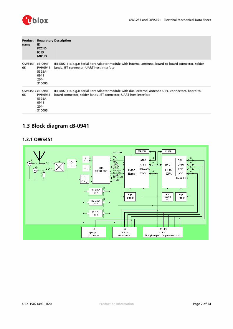
Part Number cB-ACC-54
Name Ex-IT WLAN SMA(dual-band)
OWL253 and OWS451 - Electrical Mechanical Data Sheet
UBX-15021499 - R20 Production Information Page of 30 54
Part Number cB-ACC-54
Manufacture ProAnt
Polarization Vertical
Gain / Imp. +3.0 dBi / 50ohm @ 2.4 GHz+3.0 dBi / 50ohm @ 5 GHz
Size Ø 10 x 107 mm
Connector SMA plug (inner thread and pin)
Comment To be used together with the U.FL to SMA adapter cable (cB-ACC-18 or cB-ACC-48)
Approval R&TTE, TELEC
Part Number cB-ACC-36
Name WCR-2400-RP-SMRP
Manufacture Centurion
Polarization Vertical
Gain / Imp. +2.0 dBi / 50ohm @ 2.4 GHz
Size Ø 12 x 76 mm
Connector Reverse Polarity SMA plug (inner thread and pin receptacle)
Comment To be used together with the U.FL to RP-SMA adapter cable (cB-ACC-38)
Approval FCC, IC, R&TTE, TELEC

OWL253 and OWS451 - Electrical Mechanical Data Sheet
UBX-15021499 - R20 Production Information Page of 31 54
Part Number —
Name PSTG0-2400HS
Manufacture MobileMark
Polarization Vertical
Gain / Imp. +0 dBi / 50ohm @ 2.4 GHz
Size Ø 12 x 32 mm
Connector Reverse Polarity SMA plug (inner thread and pin receptacle)
Comment To be used together with the U.FL to RP-SMA adapter cable (cB-ACC-38)
Approval FCC, IC, R&TTE, TELEC
Part Number cB-ACC-21
Name R380.500.127
Manufacture Pulse
Polarization Vertical
Gain / Imp. +2.0 dBi / 50ohm @ 2.4 GHz
Size Ø 14.3 x 61.4 mm
Connector SMA plug (inner thread and pin)
Comment To be mounted on the U.FL to SMA adapter cable (cB-ACC-18 or cB-ACC-48)
Approval R&TTE, TELEC

OWL253 and OWS451 - Electrical Mechanical Data Sheet
UBX-15021499 - R20 Production Information Page of 32 54
Part Number —
Name R380.500.125
Manufacture Pulse
Polarization Vertical
Gain / Imp. +2.0 dBi / 50ohm @ 2.4 GHz
Size Ø 14.3 x 61.4 mm
Connector Reverse Polarity SMA plug (inner thread and pin receptacle)
Comment To be used together with the U.FL to RP-SMA adapter cable (cB-ACC-38)
Approval FCC, IC, R&TTE, TELEC
Part Number —
Name R380.500.124
Manufacture Pulse
Polarization Vertical
Gain / Imp. +2.0 dBi / 50ohm @ 2.4 GHz
OWL253 and OWS451 - Electrical Mechanical Data Sheet
UBX-15021499 - R20 Production Information Page of 33 54
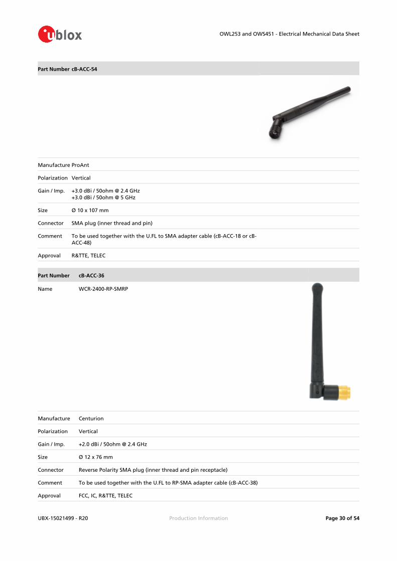
Part Number —
Size Ø 14.3 x 61.1 mm
Connector SMA plug (inner thread and pin)
Comment The difference compared to the R380.500.127 antenna is that the R380.500.124 antenna has a seal ring.To be mounted on the U.FL to SMA adapter cable (cB-ACC-18 or cB-ACC-48)
Approval R&TTE, TELEC
Part Number —
Name R380.500.139
Manufacture Pulse
Polarization Vertical
Gain / Imp. +2.0 dBi / 50ohm @ 2.4 GHz
Size Ø 14.3 x 61.1 mm
Connector Reverse Polarity SMA plug (inner thread and pin receptacle)
Comment The difference compared to the R380.500.125 antenna is that the R380.500.139 antenna has a seal ring.To be used together with the U.FL to RP-SMA adapter cable (cB-ACC-38)
Approval FCC, IC, R&TTE, TELEC
Part Number cB-ACC-28
Name NanoBlue-IP04
Manufacture Centurion

OWL253 and OWS451 - Electrical Mechanical Data Sheet
UBX-15021499 - R20 Production Information Page of 34 54
Part Number cB-ACC-28
Polarization Vertical
Gain / Imp. +2.0 dBi / 50ohm @ 2.4 GHz
Size 47.8 x 12.7 mm
Cable length 100 mm
Connector U.FL
Comment To be connected to the U.FL connector on the PCB
Approval FCC, IC, R&TTE, TELEC
Part Number cB-ACC-17
Name PlanTec m70cxr
Manufacture Reel
Polarization Vertical
Gain / Imp. +1.0 dBi / 50ohm @ 2.4 GHz
Size Ø 76.0 x 20.7 mm
Cable length 20/100/300 cm
Connector SMA plug (inner thread and pin receptacle)
Comment To be used together with the U.FL to SMA adapter cable (cB-ACC-18 or cB-ACC-48)
Approval R&TTE, TELEC
Part Number cB-ACC-37
Name PlanTec m70cxr
Manufacture Reel
Polarization Vertical

OWL253 and OWS451 - Electrical Mechanical Data Sheet
UBX-15021499 - R20 Production Information Page of 35 54
Part Number cB-ACC-37
Gain / Imp. +1.0 dBi / 50ohm @ 2.4 GHz
Size Ø 76.0 x 20.7 mm
Cable length 20/100/300 cm
Connector Reverse Polarity SMA plug (inner thread and pin receptacle)
Comment To be used together with the U.FL to RP-SMA adapter cable (cB-ACC-38)
Approval FCC, IC, R&TTE, TELEC
3.5.3 Customer specific antennas
Part Number —
Name InSide EPA WLAN
Manufacture ProAnt
Polarization Circular
Gain / Imp. +3.0 dBi / 50 ohm @ 5 GHz
Size 66 x 90 x 36 mm
Connector U.FL-R-SMT
Comment Frequency 5150 - 5350 MHz (5.0 - 6.0 GHz)
Approval FCC, IC, R&TTE
Part Number —
Name Inside EPA 2400
Manufacture ProAnt
Polarization Mixed horizontal and vertical
Gain / Imp. +3.0 dBi / 50 ohm @ 2.4 GHz
Size 66 x 90 x 36 mm
Connector U.FL-RSMT
Comment Frequency 2400 - 2485 MHz
Approval FCC, IC, R&TTE, TELEC
Part Number —
Name SDM2-2400 / 1575
Manufacture Mobile Mark
Polarization Vertical
Gain / Imp. +2.0 dBi / 50 ohm @ 2.4 GHz

OWL253 and OWS451 - Electrical Mechanical Data Sheet
UBX-15021499 - R20 Production Information Page of 36 54
Part Number —
Size Ø 65.0 x 28.6 mm
Cable length 200 mm
Connector U.FL
Comment Frequency 2400 - 2500 MHz
Approval FCC, IC, R&TTE, TELEC
4 Mounting information
4.1 Module dimensions

OWL253 and OWS451 - Electrical Mechanical Data Sheet
UBX-15021499 - R20 Production Information Page of 37 54

OWL253 and OWS451 - Electrical Mechanical Data Sheet
UBX-15021499 - R20 Production Information Page of 38 54
1.
2.
Tolerances:
Outline dimensions +/- 0.1mm
Drilled hole to outline: +/- 0.05mm
4.1.1 Mounting holes
There are 2 x 2.3mm mounting holes on cB-0941. The reasons for the 2.3mm holes are that the threaded M2 holes on the single and double row connectors are not aligned. The outer tangents of the 2.3mm holes align the module if the single row connectors are used and the inner if double row connectors are used (see Figure 11).Choose the outer tangent (CC distance 27.24mm) if the module is aligned and mounted with some other technique based on M2 screws (e.g. press-fit nuts), see Figure 12.
4.2 Using the J2/J3 board-to-board connectors
The board-to-board connector should be a 1 mm pitch one-piece part connector. The recommended manufacture is Samtec with many connector options available.Chapter 3 contains more information about the connector and the electrical interface.
4.2.1 Single row connectors

OWL253 and OWS451 - Electrical Mechanical Data Sheet
UBX-15021499 - R20 Production Information Page of 39 54
The single row connector SEI-120-02 can be used if only J2 is needed.This connector has a profile height of 1.65 mm and this has to be considered if components are to be mounted on the motherboard under the OEM Serial Port Adapter board.There are alignment pins on the bottom side of the connector.The connector is available with M2 threaded inserts that fit the mounting holes on the board (see section ). You may screw the OEM Serial Port Adapter board Suitable One-Piece Part Connectorsdirectly into these inserts. If you want to have a tighter and more secure mounting, you may use longer screws and secure it using a nut on the backside of the motherboard.Another way to mount the module is to use press-fit nuts on the motherboard and skip the M2 threads on the connector, see section for more Using Press-Fit Nuts for Mounting the Moduleinformation about press-fit nuts.
Table 8: Single row connectors from Samtec.
Samtec order number
Quote number
Equivalent part Package Remark
ASP-118645-01 55392 SEI-120-02-GF-S-AB Tube Align pin on bottom side only
ASP-118645-02 55392 SEI-120-02-GF-S-AB-TR Tape-n-Reel
Align pin on bottom side only
ASP-118579-01 55392 SEI-120-02-GF-S-M-AB Tube With M2 threaded inserts and align pin on bottom side only
ASP-118579-02 55392 SEI-120-02-GF-S-M-AB-TR Tape-n-Reel
With M2 threaded inserts and align pin on bottom side only
For technical questions regarding the Samtec connectors please contact u-blox or Samtec at [email protected]
See Figure 10 for more information about the connector and necessary measurements on the motherboard. The large mounting holes on the motherboard are designed for press-fit nuts and could be smaller if press-fit nuts are not used. The mounting holes are aligned with the outer tangent of the 2.3mm mounting holes of the module (see section #Mounting Holes).

OWL253 and OWS451 - Electrical Mechanical Data Sheet
UBX-15021499 - R20 Production Information Page of 40 54
Host PCB layout [mm] for single row connector.
4.2.2 Double row ASP-118580-01 connector
This connector is a double row connector and connects both J2 and J3. It connector has a height of 3.0 mm and this has to be considered if components are to be mounted on the motherboard under the board. The connector is also available with a height of 6.0 mm and 10.0 mm (The FSI-120 serie from Samtec).There are alignment pins on the bottom side of the connector.The connector is available with M2 threaded inserts (ASP-118580-01) that fit the mounting holes on the board. You may screw the board directly into these inserts. If you want to have a tighter and more secure mounting you may use longer screws and secure it using a nut on the backside of the motherboard.
Samtec order number
Quote number
Equivalent part Package Remark
REF-120018-01 55392 FSI-120-03-G-D-M-AB Tube With M2 threaded inserts and align pin on bottom side only
REF-120018-02 55392 FSI-120-03-G-D-M-AB-K-TR Tape-n-Reel
With M2 threaded inserts and align pin on bottom side only
For technical questions regarding the Samtec connectors please contact u-blox or Samtec at [email protected]

OWL253 and OWS451 - Electrical Mechanical Data Sheet
UBX-15021499 - R20 Production Information Page of 41 54
See figure below for more information about the connector and necessary measurements on the motherboard. The large mounting holes on the motherboard are designed for press-fit nuts and could be smaller if press-fit nuts are not used.
4.3 Using press-fit nuts for mounting the module
A press-fit nut is pressed into the PCB from the bottom side with a special press tool. M2 sized press-fit nuts are suitable for the modules (see Figure 10 and Figure 11) and are manufactured by PEM Fastening Systems ( ), part no KFS2-M2 (see Figure 12). Be careful with the distance www.pemnet.combetween the nuts regarding alignment, see the section.#Mounting Holes
Spacer-pipes are recommended to use between the PCBs when press-fit nuts are used.
4.4 Recommended M2 screw
If a double-row connector with threaded inserts or press-fit nuts are used, then recommended for mounting of modules is a ISO 7380 M2 compatible screw. A suitable screw is the BN6404 from Bossard,
, with TORX T6 head cap. See figure below.www.bossard.com

OWL253 and OWS451 - Electrical Mechanical Data Sheet
UBX-15021499 - R20 Production Information Page of 42 54
Parameter Value Unit
d2 3.5 mm
k max 1.3 mm
t max 0.8 mm
A 2.0 mm
If other type of screw is used please ensure that d2 is less than 3.8 mm otherwise components near the mounting holes can be damaged.
4.5 Using the J6 PCB solder pads
4.5.1 Host board
The host PCB footprint should not contain any traces or vias under the module except the pads interfacing the J6 pads to avoid contact with traces/vias on the module. The host pads which are soldered to the J6 pads should reach 0.5-1.0mm under the PCB and some mm outside the module. No other pads than the J6 should be soldered to the host PCB. See section for #Secondary side connectorsmore info about the J6 pads.
4.5.2 Mounting process
We strongly recommend the modules not being soldered more than 1 time after shipping from u-blox and that the modules are mounted just before the host product is being soldered the last time. Although, u-blox devices will withstand up to two reflows to an absolute maximum temperature of 250°C.
The PCB in our modules is made of Isola PCL-FRP-370HR with Chemical Gold Pads.
The modules are produced in a lead-free process with a lead-free soldering paste.
It is recommended that the customers make their own electrical, climate, stress and vibration tests on the final assembled product to secure that the manufacturing process hasn't damaged or affected the module in any way.

OWL253 and OWS451 - Electrical Mechanical Data Sheet
UBX-15021499 - R20 Production Information Page of 43 54
The modules are delivered without labels on each module when packaged on tape-and-reel. However, if they are delivered with labels on each module, the labels should be removed before the module is processed since the labels do not withstand the heat of soldering.
The device recommended maximum re-flow temperature is 245°C for 10 sec.
The device absolute maximum re-flow temperature is 250°C for 3 sec.
4.6 Antenna issues
To ensure not to cause negative influence on the RF-performance of the unit it cannot be arbitrarily mounted. This concerns the choice of enclosure material and objects in the vicinity of the unit.
A unit with an internal surface mounted antenna cannot be mounted in a metal enclosure. This restriction also includes the use of plastic with metal flakes and metallic based paint or lacquer.
The Antenna keep out Area in the picture below marks a recommended area of 10 mm clearance around the antenna that should be kept free from metal and Cu-wiring.If a metal enclosure is required, one of the external antenna options has to be used.
See section 3.2 for more information on the antenna options available.

OWL253 and OWS451 - Electrical Mechanical Data Sheet
UBX-15021499 - R20 Production Information Page of 44 54
5 Wireless LAN informationIn the tables below you can find information about wireless LAN properties.
Parameter Data
Radio Redpine Signals RS9110 + Airoha 8230
RF output power 2.4 GHz 802.11b (DSSS): +17dBm (typ.)802.11g (OFDM): +15dBm (typ.)802.11n (OFDM): +15dBm (typ.)
RF output power 5 GHz 802.11a (OFDM): +9dBm (typ.)802.11n (OFDM): +9dBm (typ.)
Receiver sensitivity See table below
Receive input level (max) -10 dBm
Output frequency 2.4 GHz 2.412 - 2.462 GHz, channel 1 - 11 (FCC domain)2.412 - 2.472 GHz, channel 1 - 13 (ETSI, TELEC domain)5 MHz channel separation
Output frequency 5 GHz 5.180 - 5.240 GHz, U-NII-1Channel 36, 40, 44, 48 (FCC, IC, ETSI domain)
5.260 - 5.320 GHz, U-NII-2Channel 52, 56, 60, 64 (FCC, IC, ETSI domain)
5.500 - 5.700 GHz, U-NII-2eChannel 100, 104, 108,112, 116, 120, 124, 128, 132, 136, 140 (FCC, ETSI domain)
5.500 - 5.700 GHz, U-NII-2eChannel 100, 104, 108,112, 116, 132, 136, 140 (IC domain)
- 5.825 GHz, U-NII-3*5.745 Channel 149, 153, 157, 161, 165 (FCC domain)
TPC and DFS slave/client operation on 5.260 - 5.320 GHz, 5.500 - 5.700 GHz20 MHz channel separation
Bluetooth co-existence Basic 2-wire
- 5.825 GHz, U-NII band-3, are only supported by modules shipped after * Frequencies 5.745 September 1, 2013.
Due to FCC rules it is not possible to upgrade modules shipped prior to the date above to get the additional channels.
5.1 Radio sensitivity OFDM
Data rate 802.11gn (channel 6, 2437MHz, dBm) 802.11an (channel 36, 5180MHz, dBm)
MCS7 -69 -68
MCS6 -70 -70

OWL253 and OWS451 - Electrical Mechanical Data Sheet
UBX-15021499 - R20 Production Information Page of 45 54
Data rate 802.11gn (channel 6, 2437MHz, dBm) 802.11an (channel 36, 5180MHz, dBm)
MCS5 -72 -72
MCS4 -76 -76
MCS3 -79 -79
MCS2 -82 -82
MCS1 -84 -83
MCS0 -87 -86
54 -73 -72
48 -75 -73
36 -78 -78
24 -83 -80
18 -85 -83
12 -87 -85
9 -88 -86
6 -89 -87
5.2 Radio sensitivity DSSS
Data rate 802.11b (channel 6, 2437MHz, dBm)
11 -86
5.5 -89
2 -91
1 -94
6 Regulatory information
6.1 European Union Regulatory Compliance
6.1.1 Declaration of conformity
Information about the regulatory compliance of the European Union for OWS451 and OWL253 is available in the available at OWS451 OWL253 Declaration of Conformity (UBX-15015229) www.u-blox.
.com

OWL253 and OWS451 - Electrical Mechanical Data Sheet
UBX-15021499 - R20 Production Information Page of 46 54
6.1.2 Equipment classes
Depending on which frequency bands this WLAN module can operate in it is defined as either class-1 or class-2 radio equipment.The End-product that utilise the module inherits the equipment class of the module.
Class-1 radio equipment can be placed on the market and put into service without restrictions.(article 1 of Commission Decision 2000/299/EC of April 6 2000)
Class-2 radio equipment is equipment for which Member States apply restrictions as indicated in Article 1(2) of the Decision, which also assigns the “Alert Sign” as “Equipment Class Identifier” for this class.
This WLAN module is defined as class-1 radio equipment when it is restricted to operate in the following frequency band
WLAN, ISM band 2400 – 2483.5 MHz
WLAN, U-NII band-2e 5470 – 5725 MHz
If the end product allows the WLAN module to be operated in the band 5150 – 5350 MHz (WLAN channel: 36 – 64) it is defined as class-2 radio equipment and must be marked accordingly.
Class-2 radio equipment must have the "alert" sign affixed on the equipment, packaging and printed in the user instruction manual.
Guidance on how the End product that utilise this module is marked in accordance with the R&TTE directive is found in the following links:
http://ec.europa.eu/enterprise/sectors/rtte/documents/index_en.htm#h2-5http://ec.europa.eu/enterprise/sectors/rtte/documents/guidance/index_en.htm
A direct link to the quick guide to the marking requirements can be found here:http://ec.europa.eu/enterprise/sectors/rtte/files/guidance/guidance_en.pdf
The WLAN module uses harmonised frequency bands thus it is comprised by subclass H01 of class 2 equipment, for which notification in accordance with article 6(4) of the R&TTE directive is not necessary.
A definition of subclasses of Class 2 equipment can be found in the following link:
http://ec.europa.eu/enterprise/sectors/rtte/files/rtte-subclass2_en.pdf
The table below shows the restrictions when operating the module within the European countries
band Channel number Channel frequency Indoor Use allowed Outdoor Use allowed Radio Equipment Class
ISM 1 - 11 2412 - 2462 MHz Yes Yes 1
U-NII 1 36 - 48 5180 - 5240 MHz Yes No 2
U-NII 2 52 - 64 5260 - 5320 MHz Yes No 2
U-NII 2e 100 - 140 5500 - 5700 MHz Yes Yes 1
U-NII 3 149 - 165 5745 - 5825 MHz No No -

OWL253 and OWS451 - Electrical Mechanical Data Sheet
UBX-15021499 - R20 Production Information Page of 47 54
1.
2.
1.
2.
For U-NII band-2 (5.260 - 5.320 GHz) and U-NII band-2e (5.500 - 5.700 GHz) the module is only allowed to operate as a DFS slave/client device.
6.2 IC and FCC compliance
See for information about the different product variants.#Product variants
To be allowed to refer to the u-blox FCC ID / IC certification number for products integrating the OWL253 module the integrator must sign the u-blox Software Configuration Control Declaration to confirm that the requirements of FCC OET KDB 594280 are fulfilled. Contact
to request the [email protected]
6.2.1 IC compliance
This device complies with Industry Canada licence-exempt RSS standard(s).Operation is subject to the following two conditions:
this device may not cause interference, and
this device must accept any interference, including interference that may cause undesired operation of the device.
Under Industry Canada regulations, this radio transmitter may only operate using an antenna of a type and maximum (or lesser) gain approved for the transmitter by Industry Canada. To reduce potential radio interference to other users, the antenna type and its gain should be so chosen that the equivalent isotropically radiated power (e.i.r.p.) is not more than that necessary for successful communication.
The device for operation in the band 5150-5250 MHz is only for indoor use to reduce the potential for harmful interference to co-channel mobile satellite systems; the maximum antenna gain permitted for devices in the bands 5250-5350 MHz and 5470-5725 MHz shall comply with the e.i.r.p. limit; and the maximum antenna gain permitted for devices in the band 5725-5825 MHz shall comply with the e.i.r.p. limits specified for point-to-point and non point-to-point operation as appropriate.
Operation in the 5600-5650 MHz band is not allowed in Canada. High-power radars are allocated as primary users (i.e. priority users) of the bands 5250-5350 MHz and 5650-5850 MHz and that these radars could cause interference and/or damage to LE-LAN devices.
This equipment complies with IC RSS-102 radiation exposure limits set forth for an uncontrolled environment. This equipment should be installed and operated with minimum distance 20 cm between the radiator & your body.
6.2.2 Conformité aux normes d’IC
Cet appareil est conforme à la(aux) norme(s) RSS sans licence d’Industry Canada.Son utilisation est soumise aux deux conditions suivantes :
Cet appareil ne doit pas causer d’interférences et
il doit accepter toutes interférences reçues, y compris celles susceptibles d’avoir des effets indésirables sur son fonctionnement.

OWL253 and OWS451 - Electrical Mechanical Data Sheet
UBX-15021499 - R20 Production Information Page of 48 54
1.
2.
Conformément aux réglementations d’Industry Canada, cet émetteur radio ne peut fonctionner qu’à l’aide d’une antenne dont le type et le gain maximal (ou minimal) ont été approuvés pour cet émetteur par Industry Canada. Pour réduire le risque d’interférences avec d’autres utilisateurs, il faut choisir le type d’antenne et son gain de telle sorte que la puissance isotrope rayonnée équivalente (p.i.r.e) ne soit pas supérieure à celle requise pour obtenir une communication satisfaisante.
Le dispositif de fonctionnement dans la bande 5150-5250 MHz est réservé à une utilisation en intérieur pour réduire le risque d'interférences nuisibles à la co-canal systèmes mobiles par satellite, le gain d'antenne maximal autorisé pour les appareils dans les bandes 5250-5350 MHz et 5470-5725 MHz doit se conformer à la pire limite, et le gain d'antenne maximal autorisé pour les appareils dans la bande 5725-5825 MHz doivent être conformes avec le pire limites spécifiées à point-à-ponctuelles et non point-à-point de fonctionnement selon qu'il convient.
Opération dans la bande 5600-5650 MHz n'est pas autorisée au Canada. Haute puissance radars sont désignés comme utilisateurs principaux (c.-àutilisateurs prioritaires) des bandes 5250-5350 MHz et 5650-5850 MHz et que ces radars pourraient causer des interférences et / ou des dommages à dispositifs LAN-EL.
Cet équipement respecte les limites d’exposition aux rayonnements IC RSS-102 définies pour un environnement non contrôlé. Il doit être installé et utilisé en maintenant une distance minimum de 20 cm entre le radiateur et votre corps.
6.2.3 FCC statement
This device complies with Part 15 of the FCC Rules. Operation is subject to the following two conditions:
this device may not cause harmful interference, and
this device must accept any interference received, including interference that may cause undesired operation.
This equipment has been tested and found to comply with the limits for a Class B digital device, pursuant to Part 15 of the FCC Rules. These limits are designed to provide reasonable protection against harmful interference in a residential installation. This equipment generates, uses and can radiate radio frequency energy and, if not installed and used in accordance with the instructions, may cause harmful interference to radio communications. However, there is no guarantee that interference will not occur in a particular installation. If this equipment does cause harmful interference to radio or television reception, which can be determined by turning the equipment off and on, the user is encouraged to try to correct the interference by one or more of the following measures:
Reorient or relocate the receiving antenna
Increase the separation between the equipment and receiver
Connect the equipment into an outlet on a circuit different from that to which the receiver is connected
Consult the dealer or an experienced radio/TV technician for help.
End product labelling requirements
For an end product using the product cB-0941 there MUST be a label containing, at least, the following information:

OWL253 and OWS451 - Electrical Mechanical Data Sheet
UBX-15021499 - R20 Production Information Page of 49 54
1.
2.
1.
2.
1.
2.
This device containsFCC ID: PVH0941IC: 5325A-0941
The label must be affixed on an exterior surface of the end product such that it will be visible upon inspection in compliance with the modular approval guidelines developed by the FCC.
FCC end product labelling
In accordance with 47 CFR § 15.19 the end product shall bear the following statement in a conspicuous location on the device:
"This device complies with Part 15 of the FCC Rules. Operation is subject to the following two conditions:
this device may not cause harmful interference, and
this device must accept any interference received, including interference that may cause undesired operation."
When the device is so small or for such use that it is not practicable to place the statementabove on it, the information shall be placed in a prominent location in the instruction manual or pamphlet supplied to the user or, alternatively, shall be placed on the container in which the device is marketed. However, the FCC ID label must be displayed on the device.
In case, where the final product will be installed in locations where the end-consumeris not able to see the FCC ID and/or this statement, the FCC ID and the statement shall also be included in the end-product manual.
IC end product labelling
User manuals for licence-exempt LPDs shall contain the following or equivalent statements in a conspicuous position:
Operation is subject to the following two conditions:
this device may not cause interference, and
this device must accept any interference, including interference that may cause undesired operation of the device.
Étiquetage du produit final conforme à IC
Les manuels d’utilisation d’appareils de faible puissance, sans licence, feront figurer à un endroit bien visible les mentions suivantes ou équivalentes:
Son utilisation est soumise aux deux conditions suivantes:
Cet appareil ne doit pas causer d’interférences et
il doit accepter toutes interférences reçues, y compris celles susceptibles d’avoir des effets indésirables sur son fonctionnement.
Antenna
Our module cB-0941 are for OEM integrations only. In the end-user product the module shall be professionally installed in such a manner that only the authorized antennas can be used.

OWL253 and OWS451 - Electrical Mechanical Data Sheet
UBX-15021499 - R20 Production Information Page of 50 54
Caution
Any changes or modifications NOT explicitly APPROVED by u-blox could cause the module to cease to comply with FCC rules part 15, and thus void the user's authority to operate the equipment.
Within the 5150 to 5250 MHz band (5 GHz radio channels 34 to 48) the module type cB-0941 is restricted to indoor operations to reduce any potential for harmful interference to co-channel MSS operation.
§15.407 statement; in case of absence of information to transmit or operational failure the module types cB-0941 will automatically discontinue transmission.
Ad-hoc frequencies
Module cB-0941 when operating under the definition of a client in 47 CFR §15.202 is preconfigured to use the most restrictive regulatory domain. For this reason the available operating frequency range is limited to channel 1 - 11 (2412 - 2462 MHz) for IEEE802.11b/g. For IEEE802.11a the available operating frequency range is limited to channels 36 - 48 (5180 - 5240 MHz).
RF-exposure statement
This equipment complies with FCC radiation exposure limits set forth for an uncontrolled environment. This equipment should be installed and operated with minimum distance 20 cm between the radiator & your body.
This equipment complies with IC RSS-102 radiation exposure limits set forth for an uncontrolled environment. This equipment should be installed and operated with minimum distance 20 cm between the radiator & your body.
Cet équipement est conforme aux limites d'exposition de rayonnement d'IC RSS-102 déterminées pour un environnement non contrôlé. Cet équipement devrait être installé et actionné avec la distance minimum 20 cm entre le radiateur et votre corps.
Any notification to the end user of installation or removal instructions about the integrated radio module is NOT allowed.
6.3 Japan Radio Equipment Compliance (TELEC)
The cB-0941 module complies with the Japanese Technical Regulation Conformity Certification of Specified Radio Equipment (ordinance of MPT N°. 37, 1981), Article 2, Paragraph 1, Item 19, "2.4GHz band wide band low power data communication system".
OWL253 and OWS451 - Electrical Mechanical Data Sheet
UBX-15021499 - R20 Production Information Page of 51 54
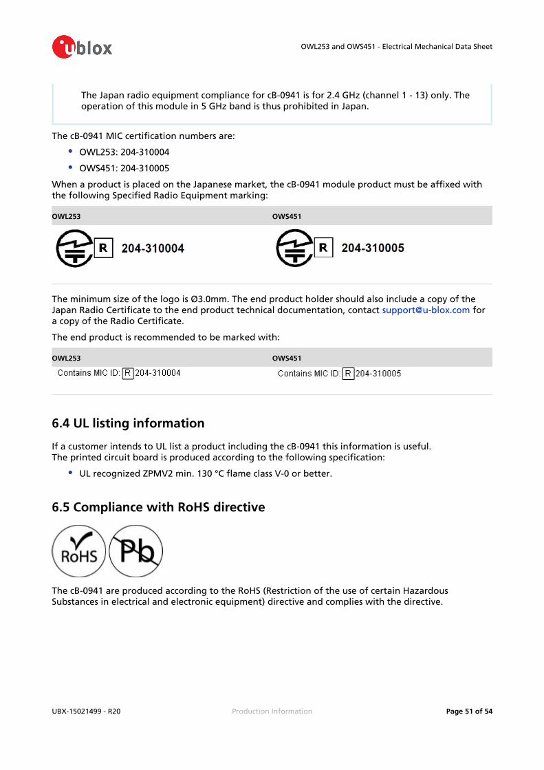
The Japan radio equipment compliance for cB-0941 is for 2.4 GHz (channel 1 - 13) only. The operation of this module in 5 GHz band is thus prohibited in Japan.
The cB-0941 MIC certification numbers are:
OWL253: 204-310004
OWS451: 204-310005
When a product is placed on the Japanese market, the cB-0941 module product must be affixed with the following Specified Radio Equipment marking:
OWL253 OWS451
The minimum size of the logo is Ø3.0mm. The end product holder should also include a copy of the Japan Radio Certificate to the end product technical documentation, contact for [email protected] copy of the Radio Certificate.
The end product is recommended to be marked with:
OWL253 OWS451
6.4 UL listing information
If a customer intends to UL list a product including the cB-0941 this information is useful.The printed circuit board is produced according to the following specification:
UL recognized ZPMV2 min. 130 °C flame class V-0 or better.
6.5 Compliance with RoHS directive
The cB-0941 are produced according to the RoHS (Restriction of the use of certain Hazardous Substances in electrical and electronic equipment) directive and complies with the directive.
OWL253 and OWS451 - Electrical Mechanical Data Sheet
UBX-15021499 - R20 Production Information Page of 52 54
7 Guidelines for efficient and safe use
7.1 General
Read this information before using your cB-0941 module.For any exceptions, due to national requirements or limitations, when using your wireless LAN module cB-0941, please contact u-blox.
Changes or modifications to the product not expressly approved by u-blox will void the user's authority to operate the equipment.
7.2 Product care
Do not expose your product to liquid or moisture.
Do not expose you product to extreme hot or cold temperature.
Do not expose your product to lit candles, cigarettes, cigars, open flames, etc.
Do not drop, throw or try to bend your product since rough treatment could damage your product.
Do not attempt to disassemble your product. Doing so will void warranty. The product does not contain consumer serviceable or replaceable components. Service should only be performed by u-blox.
Do not paint your product as the paint could prevent normal use.
If you will not be using your product for a while, store it in a place that is dry, free from damp, dust and extreme heat and cold.
The clearance and creepage distances required by the end product must be withheld when the module is installed.
The cooling of the end product shall not negatively be influenced by the installation of the module when the module is installed.
The package type of the host MCU is Wafer Level Chip Size Package (WLCSP). WLCSP components must be handled with extra care as active silicon substrate is not protected against aggressive mechanical actions. WLCSP components must also be protected from light exposure when operating. The use of a no-clean flux is highly recommended to avoid any cleaning operation, including ultrasonic cleaning methods.
Do not store the module in direct sunlight, IR- or UV light.
7.3 Radio frequency exposure
The cB-0941 wireless LAN module contains a small radio transmitter and receiver.During communication with other wireless LAN products the cB-0941 module transmits and receives radio frequency (RF) electromagnetic fields (microwaves) in the frequency range 2412 - 2462 MHz and 5180 - 5825 MHz.

OWL253 and OWS451 - Electrical Mechanical Data Sheet
UBX-15021499 - R20 Production Information Page of 53 54
The output power of the radio transmitter is very low.When using the cB-0941, you will be exposed to some of the transmitted RF energy. This exposure is well below the prescribed limits in all national and international RF safety standards and regulations.
7.4 Electronic equipment
Most modern electronic equipment, for example, in hospitals and cars, is shielded from RF energy. However, certain electronic equipment is not. Therefore:
This equipment emits RF energy in the ISM (Industrial, Scientific, Medical) band. Please insure that all medical devices used in proximity to this device meet appropriate susceptibility specifications for this type of RF energy.
7.5 Potentially explosive atmospheres
Turn off your electronic device before entering an area with potentially explosive atmosphere. It is rare, but your electronic device could generate sparks. Sparks in such areas could cause an explosion or fire resulting in bodily injury or even death.Areas with a potentially explosive atmosphere are often, but not always, clearly marked. They include fuelling areas, such as petrol station, below deck on boats, fuel or chemical transfer or storage facilities, and areas where the air contains chemicals or particles, such as grain, dust, or metal powders.
7.6 Safety compliance
In order to fulfil the safety standard EN 60950-1:2006 the wireless LAN module cB-0941 must be supplied by a Class-2 Limited Power Source.

OWL253 and OWS451 - Electrical Mechanical Data Sheet
UBX-15021499 - R20 Production Information Page of 54 54
Contact
For complete contact information visit us at www.u-blox.com
u-box Offices
North, Central and South America
u-blox America, Inc.Phone: +1 703 483 3180E-mail: [email protected]
Regional Office West Coast:Phone: +1 408 573 3640E-mail: [email protected]
Technical Support:Phone: +1 703 483 3185E-mail: [email protected]
Headquarters Europe, Middle East, Africa
u-blox AGPhone: +41 44 722 74 44E-mail: [email protected]: [email protected]
Asia, Australia, Pacific
u-blox Singapore Pte. Ltd.Phone: +65 6734 3811E-mail: [email protected]: [email protected]
Regional Office Australia:Phone: +61 2 8448 2016E-mail: [email protected]: [email protected]
Regional Office China (Beijing):Phone: +86 10 68 133 545E-mail: [email protected]: [email protected]
Regional Office China (Shenzhen):Phone: +86 755 8627 1083E-mail: [email protected]: [email protected]
Regional Office India:Phone: +91 959 1302 450E-mail: [email protected]: [email protected]
Regional Office Japan:Phone: +81 3 5775 3850E-mail: [email protected]: [email protected]
Regional Office Korea:Phone: +82 2 542 0861E-mail: [email protected]: [email protected]
Regional Office Taiwan:Phone: +886 2 2657 1090E-mail: [email protected]: [email protected]