Embed Size (px)
Citation preview

Overview of theMechanisms of Failurein Heat Treated Steel ComponentsScott MacKenzie, Houghton International, Inc.
“Primum non nocere” — “First do no harm,” attributed to the ancient Romanphysician Galen. “Declare the past, diagnose the present, foretell the future;practice these acts . . . make a habit of two things — to help, or at least to do noharm” (Ref 1).
FAILURES IN STEEL components, like anyother material, may have various consequences,such as:
� Making the device or component completelyinoperable
� Preventing an operable device from func-tioning satisfactorily
� Making the device or component unsafe orunreliable, with immediate removal fromservice required
Many aspects may also be involved in tracingback to the possible sources of failure of acomponent. Some of these sources include:
� Design� Material issues, such as improper materials
selection or material imperfections (laps,seams, inclusions, porosity, etc.)
� Fabrication and processing� Rework� Assembly� Inspection� Storage and shipment� Service conditions� Maintenance� Unanticipated service conditions
Many times, more than one factor contributes toa part failure. Rarely is it only one factor.
General Sources of Failure
Design deficiencies are a common source ofcomponent failure. Examples include the pre-sence of a sharp notch in regions of high stress ora fillet radii that is too sharp. Using a componentdesign for a new application can also lead to
unanticipated failures. Higher stresses or unan-ticipated service conditions can cause unfore-seen failure because of complex or increasedstress fields. Stress concentrations may becomemore critical because of the increase in loadingfor the new application.
Insufficient design criteria can also be thecause of unforeseen failures. Inadequateknowledge of the stress state in the componentor inadequate stress calculations can contributeto failures. Much higher stress states than initi-ally assumed or improper stress assumptions canresult in premature service failures. Lack ofconsideration of severe environmental, fatigue,or impact conditions may contribute to failure.
Material issues can usually be attributed toeither selection of material or material imper-fections rendering it unsuitable for service. In-adequate material data can also result inconditions that may contribute to failure. Forexample, adequate fatigue data, elevated-tem-perature tensile data, or creep or corrosion datamay not be available, and the designer may haveto extrapolate or estimate the effects or theseproperties.
Other sources of failure can be attributed tomaterial imperfections. For wrought products,this could be related to segregation, inclusions,porosity, laps, and seams. For castings, theseimperfections could be cold shuts, inclusions,shrinkage, voids, and porosity. Forgings canhave laps, seams, segregation, and anisotropy inproperties from forging flow lines.
In one example (Fig. 1), a large roll was heattreated, and several large cracks were observedafter inspection. This was originally attributed toquench cracking. On further examination, it wasdetermined that a lap was present in the forging,
Name ///sr-nova/Dclabs_wip/Failure_Analysis/5113_43-86.pdf/Chap_02/ 18/8/2008 2:54PM Plate # 0 pg 43
© 2008 ASM International. All Rights Reserved. Failure Analysis of Heat Treated Steel Component (#05113G) www.asminternational.org

indicated by the presence of high-temperatureoxides in the crack along the crack faces.
Manufacture and Processing. Processingcan have a large influence on properties and theresulting residual stresses. Typically, this isrelated to wrong procedures or improperly spe-cified procedures. Ambiguous processes orspecifications can also contribute to failures dueto interpretation or application. Simple thingslike improper selection of processing sequencesor procedures or specifications that were notfollowed can also contribute to failure.
Cold forming, such as stretching or deepdrawing, can develop highly localized residualstresses. Local changes in microstructure canoccur. Because of the changes in reduction, alarge anisotropy in material properties also re-sults. Due to the drawing operation, cracks ormicrocracking can occur. This could be due toimproper lubrication or improper die design.The localized changes in ductility can also con-tribute to failure.
Machining and grinding can create highresidual stresses from either machining practice(feeds and speeds) or improper cutting toolselection, material, or geometry. Grinding, if
abusive, can cause large temperature gradientsand localized overheating. This overheating cancause changes in microstructure—either loca-lized softening of the material or localizedtransformation to martensite and other trans-formation products—resulting in hard spots.
In Fig. 2, a large gear was ground after heattreatment. Because of abusive grinding, localtemperatures exceeded the austenitization tem-perature, and transformation to martensiteoccurred upon cooling. This transformation andthe resulting residual stresses caused cracking ofthe gear. Temper etch examination of the gearusing dilute nitric acid in water in the regions ofcracking showed evidence of localized abusivegrinding.
Identification of parts can also cause failure toinitiate. This is from localized impact or electro-etching. Localized mechanical stress concen-trations or changes in microstructure can occur.This creates either a mechanical or micro-structural notch or stress concentration.
Heat treatment can cause a variety of differentroot causes for failures. Overheating, decarbur-ization, quenching, tempering, annealing, andother heat treatments can cause failure to occur.
Fig. 1 A large roll was found to have cracks on the outer and inner surfaces of the forging. These cracks were found during finalinspection. During examination of metallographic sections taken from the roll, high-temperature oxides were found on the
crack faces, strongly suggesting forging laps.
44 / Failure Analysis of Heat Treated Steel Components
Name ///sr-nova/Dclabs_wip/Failure_Analysis/5113_43-86.pdf/Chap_02/ 18/8/2008 2:54PM Plate # 0 pg 44
© 2008 ASM International. All Rights Reserved. Failure Analysis of Heat Treated Steel Component (#05113G) www.asminternational.org

This could also include improper austenitizationtemperatures and times. Decarburization is theresult of a low-carbon surface from improperatmosphere control. Typically, there is a deple-ted carbon layer at the surface that, whenquenched, is softer than the core material. Thissoft layer can be completely devoid of carbon(complete decarburization) or only partiallydepleted in carbon (partial decarburization).This decarburized layer can contribute to pre-mature fatigue failures, because the surfacematerial is different than the designer expected,or failure can result from high residual stressescreated at the surface from the quenchingoperation. The low-carbon surface area can alsoresult in distortion—again, high residual tensilestresses at the surface with low surface hardness.Carburization is similar to the effects of de-carburization. In this case, there is a higher sur-face carbon than expected. High residual tensilestresses can result as well as increased distortion.
Quenching can also contribute to high resi-dual stresses or the formation of cracks ormicrocracking. Transformation stresses fromquenching cause the high residual stresses.These high residual tensile stresses can drasti-cally reduce the fatigue strength or have otherramifications in service.
Overheating can cause excessive graingrowth, with resulting increases in hardenabilityand increased embrittlement. Underheating cancause poor mechanical properties, because therewas an incomplete transformation to austeniteand therefore an incomplete transformation tomartensite. Poor mechanical properties, such aslow tensile and yield stress, and poor impactproperties may occur.
There are also several embrittlement mech-anisms caused by the use of improper temperingtemperatures. Temper embrittlement and bluebrittleness are just two of the common mech-anisms that can occur from improper heattreatment and tempering operations.
Cleaning, pickling, and electroplating op-erations can also cause potential failures orcontribute to them. Hydrogen charging of high-strength steels from the dissociation of hydro-gen on the surface of high-strength steel canoccur from cleaning operations in acids. Char-ging of hydrogen from high current densitiesin electroplating can cause hydrogen embrittle-ment unless proper baking procedures are usedto allow the hydrogen to diffuse out. Electro-plating can also cause high residual tensilestresses, which can contribute to crack initiation.
Welding can cause many different problems.These problems can be cracks that are initiatedfrom improper welding procedures, high resi-dual stresses, porosity from inadequately driedweld rods, or dirty workpieces. Microstructuralnotches or stress concentrations from the heat-affected zone and the transition to the basematerial can be the result of improper preheatand postheat. Improper weld penetration, weldgeometry, and excessive weld current (under-cutting) can also cause mechanical stress con-centrations (Fig. 3).
The mast arm failure shown in Fig. 3 (Ref 2)was the result of weld bead undercutting andpoor weldment design. Fatigue cracking initi-ated at the site of the weld toe undercut. Thislocation was a highly stressed area and the loca-tion of a large mechanical stress-concentrationfactor because of the weld toe undercut. Typical
Fig. 2 Large gear that cracked during grinding operations. Localized thermal gradients during grinding resulted in high residualstresses and eventual cracking. Temper etching (dilute nitric acid in water) revealed the presence of abusive grinding.
Overview of the Mechanisms of Failure in Heat Treated Steel Components / 45
Name ///sr-nova/Dclabs_wip/Failure_Analysis/5113_43-86.pdf/Chap_02/ 18/8/2008 2:54PM Plate # 0 pg 45
© 2008 ASM International. All Rights Reserved. Failure Analysis of Heat Treated Steel Component (#05113G) www.asminternational.org

causes of undercutting include excessive weldcurrent.
The assembly of a group of components canalso cause eventual failure. Force-fitting a com-ponent creates high residual stresses or damageand causes premature failure to occur. Incorrectplacement of a component or incorrect assemblyorder can also cause high residual stresses orfailure to occur. Improper specifications or tor-que requirements can also cause prematurefailure. Misalignment of components within theassembly could also result in inadequate servicelife, because the stresses are not what thedesigner had anticipated.
Service conditions obviously can have alarge role in the failure of a component. Theservice conditions could be normal operationsbut unanticipated by the designer. It could alsobe abnormal operations, such as speed, tem-perature (high or low), or a chemical environ-ment, that were also unanticipated. The lack ofproper scheduled maintenance can be a majorcontributor to premature failure. Maintenanceprocedures are often reduced as a cost-savingsmeasure. Inadequate lubrication or improperlubrication can also play a role in failure (Fig. 4).In the case of Fig. 4 (Ref 3), the lubricationschedule was extended to reduce aircraft
Fig. 3 Failure of a mast arm due to fatigue that initiated at a weld toe undercut. Source: Ref 2
Fig. 4 The probable cause of this accident was a loss of air-plane pitch control resulting from the in-flight failure of
the acme nut threads on the horizontal stabilizer trim systemjackscrew assembly. The thread failure was caused by excessivewear resulting from insufficient lubrication of the jackscrewassembly. Source: Ref 3
46 / Failure Analysis of Heat Treated Steel Components
Name ///sr-nova/Dclabs_wip/Failure_Analysis/5113_43-86.pdf/Chap_02/ 18/8/2008 2:54PM Plate # 0 pg 46
© 2008 ASM International. All Rights Reserved. Failure Analysis of Heat Treated Steel Component (#05113G) www.asminternational.org

downtime. This, and other contributing factors,resulted in the loss of 88 lives.
Stresses from startup can also contribute,along with rapid temperature gradients and rapidlocalized changes in the environment. Start-upprocedures and maintenance are critical forintermittent operations. Shut-down proceduresand resulting stresses are just as critical as properstartup. Inspection procedures to prevent failureare also important. Failure to properly inspectfor problems or cracking can be catastrophic(Fig. 5), (Ref 4). In this case, maintenance andinspection personnel failed to detect a fatiguecrack in the compressor stage of an aircraftengine. Upon application of power, the com-pressor stage ruptured, with shrapnel severingfuel lines and igniting the fuel, ultimately lead-ing to the loss of the aircraft.
General Practice Conductinga Failure Analysis
The primary objective of any failure analysisis to determine the primary root cause of failureand to establish the appropriate correctiveaction. There are several stages of an analysis,which can proceed one after the other or occur atthe same time. There is no set “fixed-in-stone”procedure, because it is highly dependent on thepart and procedures/capabilities of the specificlaboratory.
These stages of analysis are:
� Collection of background data� Preliminary visual examination
� Nondestructive testing� Selection and preservation of specimens� Mechanical testing� Macroexamination� Microexamination� Metallographic examination� Determination of the fracture mechanism� Chemical analysis (bulk and microanalysis)� Exemplar testing� Analysis and writing the report
These stages are described as follows, and ad-ditional information on failure analysis proce-dures is given in the chapter “General Aspects ofFailure Analysis” in this book.
Collection of Background Information
During the collection of background data, theengineer is trying to gather an understanding ofthe purpose of the part. The engineer is attem-pting to discern the design criteria, serviceconditions, and failure conditions. In the back-ground information, the operating details andmanufacturing history should be examined andcollected. This manufacturing history shouldinclude all the mechanical processing, thermalhistory or processing, and any chemical processperformed on the part.
The service history should include all themaintenance records of the part. It should alsoinclude the expected environment and loading atthe time of failure, as well as the normal environ-ment and loading. Any quality records should beexamined for discrepancies. Unfortunately,these records are not always available, and it isoften up to the experience of the engineer todetermine the quality of the part.
Preliminary Visual Examination
Documenting the failure or fracture is extre-mely important. There can never be too manydrawings or photographs. The cost of photo-graphs (especially digital) is cheap compared toanalysis. A high-quality camera with macro-capability is very important and is one of thebest tools that a failure analysis laboratory canhave. The use of gray cards to ensure propercolor rendition is also very important, becausethe color of scale or oxides can often give anindication of the temperatures that the part hasexperienced.
Sample selection is also very important. Allassociated debris should be collected and iden-tified. Similar parts should also be collected for
Fig. 5 The probable cause of this accident was the failure ofmaintenance and inspection personnel to perform a
proper inspection of a seventh-stage high compressor disk, thusallowing the detectable crack to grow to a length at which the diskruptured under normal operating conditions, propelling enginefragments into the fuselage. The fragments severed the rightengine main fuel line, which resulted in a fire that rapidlyengulfed the cabin area. Source: Ref 4
Overview of the Mechanisms of Failure in Heat Treated Steel Components / 47
Name ///sr-nova/Dclabs_wip/Failure_Analysis/5113_43-86.pdf/Chap_02/ 18/8/2008 2:54PM Plate # 0 pg 47
© 2008 ASM International. All Rights Reserved. Failure Analysis of Heat Treated Steel Component (#05113G) www.asminternational.org

comparison. In the case of a fastener failure, it isimportant that the nut and washer be collected,too. All mating pieces should be gathered forsubsequent analysis.
Any abnormal conditions should be observedand compared with new and used components.Any discoloration or debris should be noted andcollected. Any distortion of the part should benoted, along with dimensions of the part.Weather conditions at the time of failure shouldbe collected, as well as all bearing and lubrica-tion conditions and records.
During the initial wreckage analysis, thedetermination of all wreckage should be identi-fied and located on a map or grid before any istouched or moved. Photograph each piece ofwreckage and its surroundings. Inventory theparts present or missing. Determine the operat-ing conditions at time of failure. This shouldinclude the position of control surfaces, powersettings, position of throttles, and any lights orannunciations that occurred.
As best as possible during the initial exam-ination of the wreckage, the sequence of failureshould be determined. This can be accomplishedby examining chevron markings and crackorder. The parts should then be closely examinedand reassembled. DO NOT allow the fracturesurfaces to touch each other, because this cancause potential damage to the delicate surfaces.This analysis can also help determine thesequence of events leading up to failure. Pre-liminary examination of the part should note anypaint, debris, or deposits present. Alwaysremember to “do no harm.”
The visual examination should be detailed.Fracture surface crack directions should benoted, identified, and documented. Any abuse ordiscoloration should be identified, and a generalassessment of the workmanship should bedetermined. Document all findings with photo-graphy, with multiple photographs taken fromdifferent directions. The incorporation of rulersor scales is important to determine the size anddirection of fracture.
Nondestructive Testing
Nondestructive testing is very useful fordetermining the extent of cracking. Magneticparticle inspection is useful for ferrous alloys,with dye-penetrant and ultrasonic inspectionas additional methods available for initialinspection.
Magnetic particle inspection uses discon-tinuities in the magnetic field to identify cracksor discontinuities. Fluorescent dyes with smallmagnetic particles are used. These magneticparticles gather at the discontinuities in themagnetic field, indicating flaws or indications. Itis a common, sensitive, and reliable method thatis simple to learn and use. This method has nolimitation in part size but is limited to magneticmaterials. No elaborate precleaning of the sur-faces is necessary. Detection is limited to thesurface of the part or section examined. Caremust be exercised to prevent local arcing.
The dye-penetrant method is useful forexamining surface flaws or cracks. It is usedprimarily for nonferrous alloys but is used forexamining ferrous weldments for cracks andporosity. In this method, a high-wetting liquid isspread on the surface of the part. Excess liquidis wiped off. A developer is applied to the partsurface. Any cracks, flaws, or other indicationswill appear. Limitations of this method are thenecessity of cleaning the surface prior to andafter application of the indication fluid anddeveloper solution. Surface features may alsomask indications. It is simple to use, but anunderstanding of the limitations must beunderstood prior to application to a part.
Eddy-current methods depend on the princi-ple that all metals conduct electricity. An alter-nating current is applied, and eddy currentsoccur by electromagnetic induction. Cracks orother flaws cause distortions in the electro-magnetic fields, with a result of changing thefield impedance. The advantage of this methodis that subsurface discontinuities can be detec-ted. No special skill is required to use thismethod, and the method can be automated.Probe contact with the part is not needed. Lim-itations of this method are that the depth pene-tration is limited, and the part must be capable ofconducting electricity. Reference standards areneeded for specific flaw sizes and materials.Many things can influence readings, includingsegregation, carburized layers, and changes inprofile.
Ultrasonic testing uses high-frequency soundwaves transmitted through a conducting med-ium. Any discontinuous boundary can cause adeflection. This method is very sensitive and hashigh penetration. It is possible to get accuratemeasurements of flaw position and size, butreference standardsmust be used. Shape and sizecan cause errors in interpretation. Experiencedoperators are required to properly interpret the
48 / Failure Analysis of Heat Treated Steel Components
Name ///sr-nova/Dclabs_wip/Failure_Analysis/5113_43-86.pdf/Chap_02/ 18/8/2008 2:54PM Plate # 0 pg 48
© 2008 ASM International. All Rights Reserved. Failure Analysis of Heat Treated Steel Component (#05113G) www.asminternational.org

results of testing. Effects of grain size, porosity,and inclusions can also hinder interpretation.
Radiography, using x-rays, neutrons, orgamma rays, is also often used to examinestructures. Film or sensors (charge-coupled de-vices) pick up the emitting radiation, with theintensity proportional to the density of thesample. Light areas indicate a dense region, anddark areas indicate a greater exposure or lessdense region. Advantages of radiography are thedetection of subsurface and internal features atvarious depths and the documentation of thesefeatures by filmor other imaging techniques. Theprimary disadvantage is that reference standardsmust be used, and the area for testing must beenclosed to prevent radiation from leaking out.
Mechanical Testing
Mechanical testing is useful to determine theproperties of the part and to verify that it meetsexpected properties and specifications. There aremany types of mechanical testing available,including hardness, tensile testing, and impactfracture testing.
Hardness testing is probably the most versa-tile and widely used. It is often used to evaluateheat treatment and can be used as an approx-imation for tensile strength. It can be used todetect the presence of work hardening or soft-ening and hardening or softening from localizedthermal events such as grinding. For the mostpart, it is a nondestructive test. For microhard-ness testing, it is necessary to use a metallo-graphic specimen.
Tensile testing is used more to establish con-formance to specification. It is not necessary toshow inadequate ductility because of serviceloads. Because of the size of the tensile speci-men, it may not be possible to excise an appro-priately sized sample from the part. Anisotropyof properties can be expected to lower measuredtensile and yield strength properties.
Impact and fracture toughness testing istypically used to determine conformance tospecifications. Charpy impact testing has a highvariability in results and may be temperaturerelated. Results must be taken with temperaturein mind and may not correlate with real resultsbecause of size limitations. Fracture toughnesstesting and the results from KIc testing can beused in design, and the results are useful forcalculating critical flaw sizes. It can also beused to examine estimated crack growth rates;however, samples are difficult to prepare and
test. These methods also do not incorporate theeffects of residual stresses.
Selection and Preservation of Specimens
The selection and preservation of fracturesurfaces is vital to prevent the destruction ofevidence. Unprotected, the fracture surfaces orparts can become mechanically or chemicallydamaged. This damage can obliterate evidenceand make the determination of fracture difficultor impossible. Both sides of the fracture must beprotected. This is in the event that if one surfaceis damaged, the other side can be examined.Protection of the specimens during shipment isalso very important, because evidence could bedestroyed. Avoid touching surfaces with thehands, because the chemicals and acids presentcan cause artifacts or destroy data. NEVER fitsurfaces together, because the delicate fracturefeatures can be destroyed. Since both surfaceswould be damaged, it could destroy the chancesfor determining the fracture mechanism.
Cleaning of specimens is to be done onlywhen absolutely necessary. For the most part,it is required to prepare the sample for thescanning electron microscope (SEM). Dry airblasts or soft artist brushes are typically all thatis needed. Rinsing in organic solvents thenevaporating the solvent with dry air is useful forpreparing specimens for the SEM.
Chemical cleaning is generally not recom-mended under any circumstance. Foreign sub-stances such as scale or debris should bepreserved. Do not use rust inhibitors, because ofthe inevitable damage to the part and fracturesurfaces. These rust inhibitors are also extremelydifficult to remove. Avoid washing the sample orparts with water unless seawater or other che-mical is present. In this case, gently wash withdistilled water and follow that with high-qualityalcohol or acetone. Allow to dry and place in adessicator.
Plastic replicas are useful in preservingfracture surfaces and removing debris for fur-ther analysis. Softening replica tape (availableat transmission electron microscope supplyhouses) with small amounts of acetone formsplastic replicas. The softened tape is pressedgently onto the fracture surface. Additionallayers of tape, softened with acetone, are appliedto the fracture surface. After multiple layershave been applied, the entire replica is allowedto dry and then is placed in a dessicator. Whenthe part is ready to be examined, the replica is
Overview of the Mechanisms of Failure in Heat Treated Steel Components / 49
Name ///sr-nova/Dclabs_wip/Failure_Analysis/5113_43-86.pdf/Chap_02/ 18/8/2008 2:54PM Plate # 0 pg 49
© 2008 ASM International. All Rights Reserved. Failure Analysis of Heat Treated Steel Component (#05113G) www.asminternational.org

carefully removed using tweezers. Any debrison the surface is also preserved for furtheranalysis in the replica. Multiple plastic replicascan be used to clean a surface of a part. This canbe repeated as necessary.
Sectioning of Specimens
Sectioning is very important, because it cap-tures the portion of the fracture surface forexamination or the appropriate metallographicspecimen. The biggest limitation is size. It isimportant that the portion to be removed is docu-mented by photographs and sketches, showingthe location of the specimen to be removed.Preserve any fracture surface by plastic replicasor other method to prevent damage or attack.Regions adjacent to cracks are also to be pre-served and protected. Cutting the specimensshould be done very carefully so as not to causeany heat damage. Coolants are not recommen-ded, unless the material cannot be cut withoutheat generation. The use of plastic replicas isuseful for protecting surfaces and preserving anydebris present.
Opening secondary cracks is useful when theprimary fracture surface is damaged. These sec-ondary cracks may provide better information,because they are tightly closed, and the fracturesurfaces are not exposed to surface contaminantsand corrosion. Care must be taken not to damagethe primary fracture surface. Bending to openthe crack is preferable, to expose the crack face.Often, the use of a sawcut to the back of the partwill reduce the amount of force necessary toopen the secondary crack. Another method isto use a tensile machine to open the crack face.The crack opening should be measured prior toopening, and the crack opening displacementcan also be measured as the crack is slowlyopened and exposed. One technique is to im-merse the specimen in liquid nitrogen andimpact the part so that the fracture surfaces arerapidly opened. One problemwith this method isthat it is very easy to damage the fracture surfacefrom a misapplied hammer hit.
Macroscopic Examination
The macroscopic examination is conductedby a detailed examination at 1 to 100 · by eye orbinocular microscope. High-quality optics withexcellent depth of field are required to properlyexamine the fracture surfaces. This detailedmacroscopic examination can reveal a wealth of
information on the location of fracture origins,direction of cracking, configuration of the stressstate, and the last region to fail (shear lip). Thepresence of chevron marks can indicate thedirection of rapid crack growth, and the differenttextures of the fracture can differentiate betweenfast final fracture and the initiating mechanismof fracture. Different textures from the region offast fracture can indicate a different mechanism,such as fatigue, stress-corrosion cracking, orhydrogen embrittlement.
Microscopic Examination
The microscopic examination is usually con-ducted with an SEM (Fig. 6). This instrumentis probably the most useful of all instrumentsfor determining the mechanism of failure. It iscapable of a large depth of field, with magnifi-cations of 10 to 300,000 · . It allows for directexamination of specimens, and when coupledwith an energy-dispersive spectrometer, verysmall regions can be examined and analyzed forchemistry. It is very easy to use and requires verylittle training to take quality images.
Interpretation of the images requires experi-ence and understanding of the four basic modesof failure: dimpled rupture, cleavage, brittleintergranular, and fatigue. From these four basicmodes, the detailed mode can be examined, andthe failure mechanism is fit to the evidence.A greater discussion of the mechanisms of fail-ure is found later in this chapter and elsewhere inthis book.
Metallography
Metallography is a vital part of a failureanalysis investigation. It can examine crack
Fig. 6 Typical scanning electron microscope used formicroscopic analysis of a fracture surface
50 / Failure Analysis of Heat Treated Steel Components
Name ///sr-nova/Dclabs_wip/Failure_Analysis/5113_43-86.pdf/Chap_02/ 18/8/2008 2:54PM Plate # 0 pg 50
© 2008 ASM International. All Rights Reserved. Failure Analysis of Heat Treated Steel Component (#05113G) www.asminternational.org

morphology and its relationship with themicrostructure present. It can help determine thethermal history of a component or region of apart and can show if work hardening was pre-sent. There can never be too many photographsand metallographic sections. Metallographicsections should be taken away from the crackand near the determined origins of cracking.Because this method is destructive, it is under-taken last. Typically, the crack face and edgesare protected from rounding by applying sup-port. This support can be electroless nickel plateor the use of alumina beads or steel shot in themetallographic specimen, adjacent to the sur-face.
Metallographic specimens are prepared usingan epoxy or phenolic resin. The sample is placedinto a small press, and phenolic resin is pouredover the section. The press compacts the resinand forms a small, round sample that is thenpolished, etched, and examined under a metal-lographic microscope. When the specimen hascooled, it is taken out of the press and groundthrough a sequence of sandpapers. Typically, thesequence is 240, 320, 400, and 600 grit. Thespecimen is ground very flat before polishing.During polishing, the metallographic specimenis polished using a flat platen and 3 mm aluminaslurries. Final polish is accomplished using0.15 mm alumina slurry. Other polishing agentscan be used, with diamond being a very commonpolishing agent. A finished metallographicsample used for the determination of the fracturemechanism in a steel weldment is shown inFig. 7.
Examination of the metallographic specimenreveals surface imperfections, inclusions, andmicrostructural details. It can reveal the pre-sence of decarburization and improper heat
treatment. It often provides the needed docu-mentation and support for the fracture analysisand determination of the root cause of failure.
Determination of the FractureMechanism
Examination of the fracture surface andmetallography are used to determine the cause offailure. First, it is necessary to determine thefracture mode. Unfortunately, there is no clearor logical classification of fracture. Generally,classification is based on the crack growthmech-anism (see also the chapter “General Aspects ofFailure Analysis” in this book).
Ductile Fracture
On a macroscopic scale, a ductile fracture isaccompanied by a relatively large amount ofplastic deformation before the part fails. Afterfailure, the cross section is reduced or distorted.Shear lips are observed at the latter part ofthe fracture and indicate the final failure of thepart. The fracture surface is dull, with a fibrousappearance. Microscopically, ductile fractureis characterized by several distinct stages(Ref 5–8); an example is shown in Fig. 8. In thiscase, an ISO 12.9 low-alloy bolt failed by ductiletorsional overload. The fracture was smooth,with fracture initiating from the threads. Thefracture mode was microvoid coalescence(Ref 9), which occurs by the following process:
� A free surface is created from a small parti-cle. This particle can be a second-phaseparticle, dispersoid, or inclusion. The separ-ation of the metal matrix from the smallparticle at the matrix/particle interface canform this free surface, or the fracturingof the small particle can form the free sur-face.
� The free surface around the small particlecreates a void. This void grows by plasticstrain and hydrostatic stress.
� Finally, the voids grow to a size that they joinor coalescence with adjacent voids.
This process of void formation, growth, andcoalescence is shown schematically in Fig. 9. Ifthe particles are well matched to the matrix andform a strong interface between the matrix andthe particle, then the initial formation of voids isthe critical step. Fracture occurs shortly after
Fig. 7 Typical metallographic specimen. This specimen wasused to examine microstructures in a failed weldment.
Overview of the Mechanisms of Failure in Heat Treated Steel Components / 51
Name ///sr-nova/Dclabs_wip/Failure_Analysis/5113_43-86.pdf/Chap_02/ 18/8/2008 2:54PM Plate # 0 pg 51
© 2008 ASM International. All Rights Reserved. Failure Analysis of Heat Treated Steel Component (#05113G) www.asminternational.org

void formation (Ref 10). If the interface betweenthe particles and the matrix is weak, then voidsform and grow readily. Substantial plasticdeformation occurs. Fracture occurs when thevoids reach a critical size. These voids sub-stantially reduce the cross section, with theresulting local plastic instability (Ref 11). Thesevoids coalesce to form a central crack perpen-dicular to the applied tensile stress. Dependingon the applied stresses, the shape and config-uration of the dimple shape can be changed(Fig. 10). This fact is important in determiningthe type of loading during a postfracture inves-tigation. Dimples are small and can only bedetected by using electron microscopy (Fig. 11).
The presence of inclusions in steel plays amajor role in the ductility of steel. As indicatedpreviously, the inclusions fracture and separatefrom the matrix during decohesion. Therefore,the deformability of these inclusions is impor-tant to determine the ductility of steel.
Nearly all steels have nonmetallic inclusions.The size and frequency of these inclusions isdetermined by the methods described in ASTME45 (Ref 12). The cleanliness of the steel is
Fig. 8 Fracture of an ISO 12.9 bolt by ductile torsional overload. (a) Overall view of fracture. (b) Smooth and fibrous fracture as seenthrough the SEM. (c) Microvoid coalescence (dimples)
Fig. 9 Schematic showing the formation of microvoid coal-escence
Fig. 10 Schematic representation of the creation of dimplesin a loaded member by (a) simple tension, (b) shear
loading, and (c) tearing
Fig. 11 Microvoid coalescence as seen through the SEM
52 / Failure Analysis of Heat Treated Steel Components
Name ///sr-nova/Dclabs_wip/Failure_Analysis/5113_43-86.pdf/Chap_02/ 18/8/2008 2:54PM Plate # 0 pg 52
© 2008 ASM International. All Rights Reserved. Failure Analysis of Heat Treated Steel Component (#05113G) www.asminternational.org

important to the ductility of the steel. All otherthings being equal, the steel with the lowerinclusion size, shape, and frequency will have agreater ductility than another steel with a greaterinclusion count. Modern steelmaking practicesgenerally produce low inclusion content. Often,steels for aerospace applications require a fre-quency/severity determination of inclusions inaccordance with AMS 2300, AMS 2301, AMS2303, or AMS 2304 (Ref 13–16). A specific-sized test specimen must be heat treated andexamined using magnetic particle inspection.The procedures are outlined in the aforemen-tioned specifications.
The inclusions found in steels have beendivided into five categories related to theirdeformation behavior (Ref 17):
� The inclusions Al2O3 and calcium alumi-nates are produced during deoxidation ofsteel during the production of molten steel.They are brittle at practically all tempera-tures.
� Spinel-type oxides are not deformable up to1200 �C but may be deformed above thistemperature.
� Silicates of calcium, manganese, iron, andaluminum in various proportions are brittleinclusions at room temperature but becomemore deformable at higher temperatures.The formability increases as the meltingtemperature of the silicate decreases. There-fore, aluminum silicate has much less form-ability than the lower-melting manganesesilicates.
� FeO and (FeMn)O are deformable at roomtemperature but gradually become morebrittle at temperatures above 400 �C.
� Manganese sulfide (MnS) is the most com-mon inclusion found in steel, and it isincreasingly deformable as the temperaturefalls. The morphology of theMnS inclusionschanges, depending on how they wereformed.
Ductile failure can occur with any of thetypes of inclusions. This is true whether it isthe brittle alumina-type inclusions or the moreductile sulfide-type inclusions. Inclusions gen-erally initiate ductile cracking above a criticalsize. Coarser inclusion sizes tend to have a largerlocal stress-concentration factor, which cancause local decohesion and microcrack forma-tion. Work by Maropoulos and Ridley (Ref 18)has shown the effect of volume fraction of iron-alumina on the ductility of steel. Increasing
amounts of inclusions reduce the ductility of thesteel. A reduction in the yield stress, due to thestress concentrations around the inclusions, isevident at low volume concentrations of inclu-sions.
The presence of inclusions in the size range of1 to 30 mm reduces the energy absorbed duringductile fracture. Fine dispersions of ductileinclusions will delay the onset of cleavage-typefracture by localized relaxation of stresses. Atthe same time, the yield stress also increases.
During deformation, forming, or forging, theductile inclusionMnS has a marked effect on theductility of the final product. Types 1 and 2MnSinclusions will elongate on deformation, whiletype 3 MnS inclusions will rotate into the rollingplane. This will reduce toughness and ductilityin the transverse direction. Type 2 inclusions arethe most harmful to ductility and toughness, sosome effort is being made to eliminate theseinclusions by ladle additions of other strongsulfide formers, such as titanium, zirconium, andcalcium.
Ductility is also influenced by the fact thatMnS contracts more than the iron matrix uponcooling. The bond between the MnS inclusionand the matrix is not strong enough to preventmicrovoid formation. Because MnS inclusionstend to form as strings or stringers along therolling direction, the toughness and ductilityare strongly influenced in the rolling direction.Transverse to the rolling direction, ductility andtoughness are much worse.
In a similar fashion to that of inclusions, thedistribution of carbides can also influence thetoughness and ductility of the steel. The strainneeded for void formation decreases withincreasing carbide volume fraction. Spheroidalcarbides will not crack at small strains andexhibit decohesion. Spheroidized steel is muchmore ductile than similar steel of the samehardness containing only ferrite and pearlite.Pearlite has a lower critical strain for void for-mation. In addition, when a crack or void formsin a pearlitic matrix, it will tend to run alongthe length of a pearlite lamella. Examining thistype of fracture under the SEM reveals that thebase of the dimples contain fractured pearlitelamella.
Brittle Fracture
Very little plastic deformation and a shinyfracture surface characterize brittle fractures.Often, chevron patterns point back to the origin
Overview of the Mechanisms of Failure in Heat Treated Steel Components / 53
Name ///sr-nova/Dclabs_wip/Failure_Analysis/5113_43-86.pdf/Chap_02/ 18/8/2008 2:54PM Plate # 0 pg 53
© 2008 ASM International. All Rights Reserved. Failure Analysis of Heat Treated Steel Component (#05113G) www.asminternational.org

of failure (Fig. 12) (Ref 19). It can occur at lowstress and propagate with rapidity, often atspeeds approaching the speed of sound in thefailed material.
Since the early 1940s, there has been tre-mendous growth in the number of large weldedstructures. Many of these structures have failedcatastrophically in service, most notably the“Liberty ships” (Ref 20) used to transport warmaterial during World War II. Analysis of thefracture surfaces of the failures (Ref 21) indi-cated that they initiated at a notch and propa-gated with no plastic deformation. Thesenotches were of three types:
� Design features: Structural members wererigidly joined at angles less than 90� andthen welded.
� Fabrication details: Procedures used duringthe manufacture of the part caused theformation of notches. Welding arc strikes,gouges, and fitting procedures createdphysical notches. Welding procedures and
heat treatment caused metallurgical ormicrostructural notches to occur from abruptchanges in microstructure or the productionof microstructures that were brittle. Featuressuch as porosity fromwelding or casting alsocaused brittle fracture initiation.
� Material flaws: These flaws resulted frommelt practice at the mill and appeared aslarge inclusions, internal oxidation, porosity,or segregation.
In brittle fractures, limited energy is absorbedby the fracture. Energy is absorbed throughregions of small plastic deformation. Individualgrains separate by cleavage along specificcrystallographic planes. This is shown in Fig. 13.
Visually, little or no plastic deformation ordistortion of the shape of the part characterizesbrittle fractures. The fracture is usually flat andperpendicular to the stress axis. The fracturesurface is shiny, with a grainy appearance.Failure occurs rapidly, often with a loud report.Because the brittle cleavage is crystallographicin nature, the fracture appearance is faceted.Often, other features are present, such as riverpatterns (Ref 23). These are shown schemati-cally in Fig. 14.
There are three basic factors that contribute toa cleavage type of fracture in steels. They are:
� Triaxial stress state that forms at a notch,similar to that described previously
� Low temperature� High strain rate or rapid loading rate
These three factors do not have to be presentfor cleavage-type fracture to occur. Most brittle,cleavage-type fractures occur when there is atriaxial stress state and low temperature. This isFig. 12 Chevron markings point back to the origin of failure
in brittle steels. Source: Ref 19
Fig. 13 Cleavage fracture in a low-carbon steel, seen through an SEM. Cleavage fracture in a notched impact specimen of hot-rolled1040 steel broken at �196 �C (�320 �F), shown at three magnifications. The specimen was tilted at an angle of 40� to the
electron beam. The cleavage planes followed by the crack show various alignments, as influenced by the orientations of the individualgrains. Grain A, at center in fractograph (a), shows two sets of tongues (see arrowheads in fractograph b) as a result of local cleavage alongthe {112} planes of microtwins created by plastic deformation at the tip of the main crack on {100} planes. Grain B and many other facetsshow the cleavage steps of river patterns. The junctions of the steps point in the direction of crack propagation from grain A through grainB, at approximately 22� to the horizontal plane. The details of these forks are clear in fractograph (c). Source: Ref 22
54 / Failure Analysis of Heat Treated Steel Components
Name ///sr-nova/Dclabs_wip/Failure_Analysis/5113_43-86.pdf/Chap_02/ 18/8/2008 2:54PM Plate # 0 pg 54
© 2008 ASM International. All Rights Reserved. Failure Analysis of Heat Treated Steel Component (#05113G) www.asminternational.org

actuated by a high rate of loading. Many types oftests have been developed to determine thesusceptibility of steels to brittle behavior. Thesetests include the Charpy impact test (ASTME23) (Ref 24) and the fracture toughness test(ASTM E399) (Ref 25). Others include the nil-ductility test (ASTM E208) (Ref 26) anddynamic tear test (ASTM E604) (Ref 27).
The notch toughness of low- and medium-strength steels is highly dependent on tempera-ture. There is a transition from ductile fracture tobrittle fracture as the temperature decreases.One criterion for the transition temperature is thenil-ductility temperature (NDT). The NDT is thetemperature where fracture becomes 100%cleavage, and there is essentially no plasticdeformation.
Changes in the NDT can be produced bychanges in microstructure and chemistry. Thelargest change can be effected by changes in theamount of carbon and manganese. The NDT islowered by approximately 6 �C (10 �F) forevery 0.1% increase in the manganese con-centration. Increasing the carbon content alsolowers the NDT. The manganese-carbon ratioshould be approximately 3 to 1 for good notchtoughness.
Decreasing the concentration of phosphorusalso decreases the NDT. Nitrogen causes theNDT to increase (more brittle). However,because of the interaction with other alloyingelements in steel, it is difficult to quantify theincrease of NDT with increasing nitrogen con-centration.
Fig. 14 Schematic of river patterns formed in brittle materials. (a) Tilt boundary. (b) Twist boundary. Source: Ref 23
Overview of the Mechanisms of Failure in Heat Treated Steel Components / 55
Name ///sr-nova/Dclabs_wip/Failure_Analysis/5113_43-86.pdf/Chap_02/ 18/8/2008 2:54PM Plate # 0 pg 55
© 2008 ASM International. All Rights Reserved. Failure Analysis of Heat Treated Steel Component (#05113G) www.asminternational.org

Nickel is beneficial for increasing ductility.Up to 2% Ni is effective in lowering the NDT.Increasing concentrations of silicon have theeffect of increasing the NDT. Chromium hasnearly no effect, while molybdenum is extre-mely effective in increasing the ductility ofsteels and drastically decreasing the NDT.Oxygen strongly decreases the ductility. It canalso cause an increased propensity for inter-granular fracture by creating brittle oxides at thegrain boundaries. Decreasing the grain size has astrong effect on increasing the ductility andnotch toughness.
Section thickness can also influence ductileand brittle behavior (Ref 28). The results showedthat there was considerable variation of tough-ness with the thickness of the specimen (Ref 29,30). Further, at large thickness, the toughnessappeared to reach a constant value (Fig. 15)(Ref 31). Within this curve, there are threeapparent regions. First, there is the region wheremaximum toughness is obtained (thin sections).Second, there is the region of intermediatetoughness, and lastly, a region with relativelyconstant toughness (thick sections).
In the first region, the fracture appears toconsist entirely of a shear lip, or, in other words,the fracture surface is inclined at an angleof approximately 45� to the tensile axis. In thissituation, the stress in the direction of thethickness of the specimen tends toward zero,and a state of plane stress is achieved. As thespecimen is pulled, it experiences buckling. Be-cause of this buckling, yielding occurs on thethrough-thickness planes at an angle of 45� tothe tensile axis. Crack extension occurs bysliding. This sliding motion is achieved by themovement of a number of screw dislocations(Ref 32, 33) on the 45� plane, as shown inFig. 16.
In the intermediate range, the fracture beha-vior is complicated. The fracture does not con-sist of entirely slant-type fracture, nor does itcontain entirely a flat plane-strain-type fracture.Instead, the regions of flat and slant fracture areapproximately equal. At the thin end of thethickness range, the slant ligaments on eitherside of the testpiece carry most of the load. Atthe thick end of the range, the side ligamentscarry a much smaller percentage of the load. Theamount of flat fracture increases. This is shownschematically in Fig. 17. It has been found (Ref28) that the amount of flat fracture depends onlyon the thickness of the test specimen and wasindependent of crack length.
In the third region, the fracture consists ofpredominantly flat fracture. Some evidence ofvery small shear lips may be present at the laterpart of fracture. Fracture is catastrophic andrapid. No plastic deformation is evident. In thisthird region, any increase in the thickness of thetestpiece causes no further decrease in thetoughness.
These fracture patterns are useful in deter-mining the state of stress within a failed com-ponent and can help to understand themechanism of failure.
One famous failure involving brittle fracturewas the “Great Boston Molasses Disaster”
Fig. 15 Variation of toughness with thickness Fig. 16 Mode of separation in a thin sheet
56 / Failure Analysis of Heat Treated Steel Components
Name ///sr-nova/Dclabs_wip/Failure_Analysis/5113_43-86.pdf/Chap_02/ 18/8/2008 2:55PM Plate # 0 pg 56
© 2008 ASM International. All Rights Reserved. Failure Analysis of Heat Treated Steel Component (#05113G) www.asminternational.org

(Ref 34). In this failure, the United StatesAlcohol Company fabricated a large cast ironmolasses tank in Boston in December 1915. Thistank was 27 m (90 ft) wide and 17.7 m (58 ft)tall, with a head of 15 m (49.5 ft) of molasses. Itwas fabricated of cast iron plates riveted toge-ther. It held 8.7 · 106 L (2.3 million gal) ofmolasses, ostensibly used for the fermentation ofethanol used for liquor. The man who oversawconstruction could not read blueprints, nor did
he have any technical training. No engineers orarchitects were consulted to ensure that the tankwas constructed safely. On January 15, 1919, thetank exploded with great force, and the streets ofBoston were flooded with waves of molassesfrom 2 to over 4 m (8 to 15 ft) tall (Fig. 18). Thisgreat wall of molasses was reported to havemoved at speeds up to 35 miles (56 km) perhour and devastated a large section of Bostonalong Commercial Street between Copps Hilland the playground of North End Park. Half-inchsteel plates were torn apart, and these plateswere thrown with enough force to cut girders ofthe elevated railway. This explosion, and thesubsequent wave of molasses, resulted in 21people killed, 150 people injured, many build-ings destroyed, and an entire area devastated.The elevated train trestles were knocked over.Early accounts of the disaster included reportsthat the tank was destroyed by anarchists. In atrial, it was found that the company was liablefor $628,000 in damages (in 2007 dollars,approximately $7,000,000). Investigation manyyears later indicated that the probable cause wasbrittle fracture of the tank at the rivets, with thetemperature below the ductile-to-brittle transi-tion temperature. One interesting result of thisdisaster was that Massachusetts and many otherstates created laws to certify engineers and toregulate construction. It also required stampeddrawings certifying that an engineer hadreviewed the plans. It was this failure that wasthe origin of the professional engineer’s licenseand stamp, as it is known today (2007). As a sidenote, the 18th Amendment was ratified andProhibition signed into law on January 16, 1919.
In another example of brittle fracture, an AISI4330V hook-point, used for the arrestment ofFig. 17 Schematic of fracture in the intermediate range
Fig. 18 The Great Boston Molasses Disaster. Twenty-one people were killed and over 150 buildings destroyed as the result of2.3 million gal of molasses flooding North Boston.
Overview of the Mechanisms of Failure in Heat Treated Steel Components / 57
Name ///sr-nova/Dclabs_wip/Failure_Analysis/5113_43-86.pdf/Chap_02/ 18/8/2008 2:55PM Plate # 0 pg 57
© 2008 ASM International. All Rights Reserved. Failure Analysis of Heat Treated Steel Component (#05113G) www.asminternational.org

naval aircraft on landing, failed during fieldtrials during the 13th arrestment. The landingconfiguration was severe, with high aircraft sinkrates, high aircraft gross weight, and landing at alarge angle to the cable. The hook-point failed atthe inner fillet radius of the right-hand lug(Fig. 19). The hook-point successfully engagedthe arrestment cable, with no other aircraftdamage. The part was forged, machined, heattreated, and hard surfaced in the cable groove,using a high-velocity oxyfuel coating for wearresistance. Examination showed that the micro-structure of the hook-point was quenched andtempered martensite. Hardness measurementsshowed that the hook-point had a substantiallyhigher hardness (HRC 54) than the specifiedhardness of HRC 46 to 48. The chemistry of thehook-point indicated that it was at the high sideof the specification, increasing the hardenabilityof the steel and increasing the resistance totempering. Hydrogen measurements indicatedthat the hydrogen content was 0.2 ppm. Thehigh strain rate during landing and the lowconcentration of hydrogen precluded failure byhydrogen embrittlement. An SEM examinationof the fracture surface showed that the fracturecontained microvoid coalescence and quasi-cleavage, suggestive of brittle failure (Fig. 20).Charpy impact testing showed that the impacttoughness of the as-received part was sig-nificantly lower than a part of the same chem-istry properly tempered to HRC 46. Finiteelement analysis showed a high localized stressconcentration at the lug inside fillet radius.It also showed that the stresses were highlytriaxial. Based on the analysis, it was determinedthat the hook-point lug failed by quasi-cleavage,
and that the failure was aggravated by high localstress concentration at the fillet radius, improperheat treatment (making the material more
Fig. 19 Arresting gear hook-point, manufactured from AISI 4330V, that failed during landing. Failure occurred at the inner filletradius of the right-hand lug
Fig. 20 SEM fractographs showing (a) location of origin at theinner fillet radius and (b) quasi-cleavage evident on
the fracture surface
58 / Failure Analysis of Heat Treated Steel Components
Name ///sr-nova/Dclabs_wip/Failure_Analysis/5113_43-86.pdf/Chap_02/ 18/8/2008 2:55PM Plate # 0 pg 58
© 2008 ASM International. All Rights Reserved. Failure Analysis of Heat Treated Steel Component (#05113G) www.asminternational.org

brittle), and extremely high dynamic loading. Itwas recommended that the radius be made largerto reduce the stress concentration and also toretemper the hook-points to meet specification.
Intergranular Brittle Fracture
Another form of brittle fracture is calledintergranular cracking. In this fracture mechan-ism, failure occurs by decohesion along grainboundaries and not on specific crystallographicplanes, such as in cleavage fracture. Inter-granular cracking can have several differentcauses. Typical causes of intergranular crackingin steel alloys include:
� Quench-age embrittlement: Cooling of car-bon steels and low-alloy steels from sub-critical temperatures can precipitate carbideswithin the microstructure. The strength israised, but toughness is lost.
� Quench cracking: During quenching, thetransformational and residual stressesdeveloped during quenching of steels cancause cracking during heat treatment.
� Tempered martensite embrittlement: Withinthe range where blue-purple oxides can formon steels (230 to 370 �C, or 450 to 700 �F),precipitates can form that increase the tensilestrength and hardness while reducing theductility and toughness.
� Temper embrittlement: Quenched steelscontaining appreciable amounts of manga-nese, silicon, nickel, or chromium are sus-ceptible to temper embrittlement if theycontain even trace amounts of antimony, tin,or arsenic. Embrittlement of susceptiblesteels can occur after heating in the range of370 to 575 �C (700 to 1070 �F) but occursmost rapidly at approximately 450 to 475 �C(840 to 885 �F).
� Graphitization: This happens when thepearlite in steels begins to decompose intoferrite and graphite following very long,high-temperature service, for example, insteam power stations. For these applications,a few steels turn out to be satisfactory, whilemany others are subject to graphitization.
� Internal oxidation: This is one of the com-mon failures in high-temperature, oxidizingconditions.
� Liquid metal embrittlement or solid metalembrittlement: Intermetallic compoundsform at grain boundaries when low-melting-temperature metals (cadmium, zinc, etc.)
penetrate by diffusion. An example would begalvanized steel where the zinc has diffusedinto the steel in the vicinity of 420 �C(787 �F).
� Hydrogen embrittlement: The presence ofhydrogen and static loads or a low strain ratecan result in hydrogen embrittlement.
� Stress-corrosion cracking� Grain-boundary decohesion at elevated
temperatures (creep rupture)
The fracture surface appearance of inter-granular cracking is generally shiny and faceted.It has a “rock-candy” appearance. Often, whenthe mechanism is from corrosion, the corrosionproduct is present. This can dull the appearanceof the facets. The appearance of intergranularfracture is most clearly seen in the electronmicroscope, and an example is shown in Fig. 21.
Quench cracking is the limiting case ofexcessive residual stresses exceeding the tensilestrength of the material. Two processes con-tribute to quench cracking, as well as distortionand residual stresses. The first process is thestress from the volume expansion of martensiteduring transformation from austenite to mar-tensite. The second source is from thermal stressdue to differential contraction due to differentcooling rates in the steel. The transformationalstress from the formation of martensite is pri-marily responsible for cracking during quench-ing, and thermal stresses from differentialcooling are usually from subcritical heat treat-ments such as annealing.
During quenching, the volume expands fromthe close-packed face-centered cubic structureof austenite to the body-centered tetragonalstructure of martensite. This volume expansion
Fig. 21 Intergranular fracture from hydrogen embrittlement,as seen through the SEM
Overview of the Mechanisms of Failure in Heat Treated Steel Components / 59
Name ///sr-nova/Dclabs_wip/Failure_Analysis/5113_43-86.pdf/Chap_02/ 18/8/2008 2:55PM Plate # 0 pg 59
© 2008 ASM International. All Rights Reserved. Failure Analysis of Heat Treated Steel Component (#05113G) www.asminternational.org

is approximately 4% and is related to the carboncontent of the steel. During quenching, the outersurface of the part cools first and transforms tomartensite. There is an attendant volumeexpansion at the surface, and the untransformedand still hot interior surface usually has suffi-cient plasticity to accommodate the changes inthe part volume. The outside surface is in com-pression. Upon cooling, the interior of the partalso transforms to martensite but is constrainedby the hard outside surface layer of previouslytransformed martensite. On the transformationof the inner core, a volume expansion occurs inthe interior of the part, and the outer surface isplaced in tension. If quenching is severe, theresulting tensile residual stresses can exceed theultimate tensile stress of the surface untemperedmartensite. Cracking is intergranular and oftenexhibits an oxide scale on the fracture surface. Ifcracking occurred during quenching, remnantsof quench oil can be found on the surface of thecrack, and often, elevated-temperature scale isapparent. Cracking can be delayed due to thetransformation of retained austenite. This is onereason why it is recommended to temper partsimmediately after quenching. Should delayedquench cracking occur, then the temper scaleis thinner and often shows the characteristictemper colors, indicative of the temper tem-perature. High-carbon steels and steels with highhardenability are the most prone to quenchcracking.
Surface features such as sharp radii, largechanges in section, or the presence of laps, burrs,rough-machined surfaces, and other surfacediscontinuities increase the constraint duringquenching and increase the propensity towardquench cracking.
Quench cracking can be mitigated byimproved surface condition and the removalof scale, burrs, and sharp edges. Geometrychanges, by increasing transitions from thinto thick sections, and generous radii can alsohelp reduce quench cracking. The use of higher-hardenability alloys will also reduce the pro-pensity for cracking, because it will allow areduced quench rate to achieve the same prop-erties. Reducing the austenitizing temperatureor reducing the temperature differential betweenthe austenitizing temperature and the quenchanttemperaturewill reduce the propensity for crack-ing. Often, the geometry is set, as is the alloy ofthe part. In this case, the heat treater can reducethe quench rate or use martempering to reducequench cracking.
Martempering is the process of using high-temperature quench oils and quench oil tem-peratures of 90 to approximately 200 �C (200 to400 �F). The part is quenched into the high-temperature oil, and the parts are allowed toequilibrate or at least minimize the temperaturegradient across the interior of the part. The partis then removed from the oil and allowed to coolin any convenient manner. This method hasproven to be very effective in reducing quenchcracking as well as distortion from quenching.
A long pinion gear failed in service near themidlength of the shaft (Fig. 22). One gear toothfractured during service, resulting in the gearbeing removed from service and sent to thelaboratory for failure analysis. Magnetic particleinspection, using a fluorescent dye, revealedthe presence of multiple linear indications oncracking of the gear tooth faces (Fig. 23).Examination of the fracture surface showed adiscolored region at the origin of cracking(Fig. 24). This discolored region was attributed
Fig. 22 As-received pinion gear that failed in service
Fig. 23 Magnetic particle inspection of the failed pinion gearshowed arc-shaped cracks on the gear tooth faces.
60 / Failure Analysis of Heat Treated Steel Components
Name ///sr-nova/Dclabs_wip/Failure_Analysis/5113_43-86.pdf/Chap_02/ 18/8/2008 2:55PM Plate # 0 pg 60
© 2008 ASM International. All Rights Reserved. Failure Analysis of Heat Treated Steel Component (#05113G) www.asminternational.org

to oxidation that occurred during heat treat-ment. The coloration of the oxide scale sug-gested that the oxidation occurred during
tempering (Fig. 25, 26). If the crack was pre-existing prior to heat treatment, it would bedarker and thicker.
Examination of the tooth faces showed sec-ondary cracking at regions of tearing andsmearing along the tooth face (Fig. 27), sug-gestive of abusive machining practice, includingthe use of a tool that was dull or excessive feedsand cutting speeds.
Region of Cracking
Fig. 24 Overall view of the cracked pinion showing the location of the fracture and the presence of a discolored region
FractureOrigins
Region of Discoloration
Fig. 25 Closeup of the fracture region showing the dis-colored region. The color of the oxidation indicated
that the crack occurred after quenching and during the temperingoperation.
Region of Discoloration
Smeared surface showing
secondary cracking
Fig. 26 Roughmachining at the surface of the tooth showingsmearing and tearing of themachined surface. This is
suggestive of abusive machining, due to dull cutting tools,inadequate coolant, or excessive speeds and feeds.
Overview of the Mechanisms of Failure in Heat Treated Steel Components / 61
Name ///sr-nova/Dclabs_wip/Failure_Analysis/5113_43-86.pdf/Chap_02/ 18/8/2008 2:55PM Plate # 0 pg 61
© 2008 ASM International. All Rights Reserved. Failure Analysis of Heat Treated Steel Component (#05113G) www.asminternational.org

Metallography of the teeth showed no evi-dence of burning or excessive temperature. Theroot of the tooth showed little evidence of properhardening or case (Fig. 28). The microstructurein the root consisted of ferrite and pearlite, withlightly tempered martensite, further suggestinginadequate heat treatment. The tooth tip showeda fine-grainedmartensitic structure. No evidenceof overheating was present. Examination ofthe tooth surface showed tears and smearing.Microhardness of the hardened regions of thetooth showed a hardness of HRC 58, while theroot of the tooth was HRC 29, consistent withthe observed microstructure.
Investigation of the induction heat treatingconditions revealed that the concentration of thequenchant used was approximately 5%, while6 to 10% was specified. The concentration wascontrolled solely by refractometer. Contamina-tion of the quenchant was unknown.
Based on the evidence, it was determined thatfracture and failure of the pinion gear tooth was
caused by quench cracking, aggravated byimproper concentration control and induction-hardening parameters. The situation was furtheraggravated by poor machining practice, creatingtearing and smearing at the surface.
Often, quench cracking can result not fromheat treating operations but from other sources,such as abusive grinding (Fig. 29). In this case, alarge gear was found to be cracked. As is usuallythe case, the heat treater was blamed. Temperetching of the region of cracking showed a dar-kened region, suggesting overtempering of thepart in a localized region.
Localized overheating during service can alsoresult in quench cracking. A hook-point, usedfor catching the large cable on an aircraft carrier,showed evidence of cracking in the cable groove(Fig. 30) after a carrier landing. The hook-pointwas manufactured from AMS 6411 (AISI4330V), heat treated, and a high-velocity oxy-fuel (HVOF) coating was applied. Imprints ofthe arresting cable were left in the cable groove.
Fig. 27 Secondary cracking evident at regions of abusivemachining
Fig. 28 Metallographic specimen of the pinion showinginadequate case at the root of the tooth. Etched in
0.5% nital
Fig. 29 Large gear that showed evidence of cracking. (a) As-received gear. (b) Crack evident on gear face. (c) Region after temperetching showing evidence of abusive grinding
62 / Failure Analysis of Heat Treated Steel Components
Name ///sr-nova/Dclabs_wip/Failure_Analysis/5113_43-86.pdf/Chap_02/ 18/8/2008 2:55PM Plate # 0 pg 62
© 2008 ASM International. All Rights Reserved. Failure Analysis of Heat Treated Steel Component (#05113G) www.asminternational.org

The vertical cracks were exposed using liquidnitrogen and impact loading. The crack faceswere discolored with a golden tint; they weresubsequently examined using the SEM(Fig. 31). The cracks were intergranular along
prior-austenite grains. The laboratory fractureshowed microvoid coalescence. The cracksshowed three distinct regions: incipient meltingat the surface, intergranular regions, andlaboratory-induced ductile fracture (Fig. 32).
A metallographic section (Fig. 33) throughthe vertical cracks showed untempered marten-site at the surface, a transition region of over-tempered martensite, and finally, a region oftempered martensite. No evidence of the HVOFcoating was observed at the crack initiation site.Hardness in the core was KHN 460. Hardness inthe transition region was KHN 390, and thesurface had a hardness of KHN 620. Themicrostructure is similar to a weldment heat-affected zone and shows that a significant heatevent occurred.
Chemical analysis showed that the materialconformed to AMS 6411, with alloying ele-ments at the top of the range increasing thesensitivity to quench cracking. Hydrogen ana-lysis indicated 0.8 ppm hydrogen. The levels ofhydrogen present and the high strain rate of
Fig. 31 SEM examination of the vertical cracking. “A” indicates the presence of intergranular cracking along prior-austenite grainboundaries. “B” indicates microvoid coalescence from the laboratory fracture during the exposure of the crack face.
Fig. 30 Arresting gear hook-point showing vertical crackingin the cable groove and evidence of localized heat-
ing (from the temper colors in the cable groove)
Overview of the Mechanisms of Failure in Heat Treated Steel Components / 63
Name ///sr-nova/Dclabs_wip/Failure_Analysis/5113_43-86.pdf/Chap_02/ 18/8/2008 2:55PM Plate # 0 pg 63
© 2008 ASM International. All Rights Reserved. Failure Analysis of Heat Treated Steel Component (#05113G) www.asminternational.org

loading precludes hydrogen embrittlement as apossible failure mechanism.
Based on the analysis, it was determined thatthe vertical cracking in the cable groove was the
result of transformational stresses from fric-tional heating during capture of the arrestingcable by the hook-point. The mechanism issimilar to quench cracking and was aggravated
Fig. 33 Metallographic section through the vertical crack showing (from right to left) a lightly etching region of fine-graineduntempered martensite, a transition region of overtempered martensite, and a region of nominally tempered martensite.
Hardness in the untempered martensite was KHN 620. The transition region showed a hardness of 390 KHN, and the nominal corehardness was KHN 460
Fig. 32 Exposed crack face showing two distinct regions on the crack face. “A,” region of incipient melting. “B,” intergranularfracture
64 / Failure Analysis of Heat Treated Steel Components
Name ///sr-nova/Dclabs_wip/Failure_Analysis/5113_43-86.pdf/Chap_02/ 18/8/2008 2:55PM Plate # 0 pg 64
© 2008 ASM International. All Rights Reserved. Failure Analysis of Heat Treated Steel Component (#05113G) www.asminternational.org

by the higher-than-normal hardenability of thealloy. Recommendations included the applica-tion of a different HVOF coating to better resistthe frictional heating of the cable during carrierarrestments.
Tempered martensite embrittlement(TME) may not be associated with impurityatoms segregating to prior-austenite grain boun-daries. The most common factor in TME isthe formation of cementite during tempering(Ref 35). When a given steel has a low impuritycontent, the source of TME is the decompositionof retained austenite during the second stage oftempering. Thomas first proposed this mech-anism (Ref 36). This was found when transmis-sion electron microscopy showed the presenceof thin regions of retained austenite betweenmartensite in as-quenched steels, which subse-quently transformed to cementite on temperingin the range of 230 to 470 �C (450 to 700 �F).
The presence of phosphorus also plays a role.If two steels are compared, one containing ahigher concentration of phosphorus, the steelwith the higher phosphorus content will havepoorer impact properties than an identical steelwith a lower phosphorus level. This will remaintrue through the entire range of tempering tem-perature up to approximately 500 �C (932 �F).The fracture mode is intergranular along prior-austenite grain boundaries (Ref 37). It is likelythat phosphorus is present at the prior-austenitegrain boundaries. It is only after cementite pre-cipitates in the tempered martensite that TME isfully present. Often, the presence of molybde-num at concentrations up to approximately 0.5%will reduce the effect of TME.
On June 19, 1974, during a cold start after along shutdown for repairing the TennesseeValley Authority Gallatin No. 2 unit, the inter-mediate-pressure/low-pressure rotor burst atapproximately 3400 rpm. The rotor had been inoperation for 106,000 h from its operationalstart in May 1957 (Ref 38). The burst rotor wasforged from an air-melted ingot. This ingot wasproduced by a large region of MnS segregationzone that was present at the center of the ingot,which was subsequently bored by machiningduring fabrication of the rotor. The steamtemperature was 566 �C (1050 �F). Temperedmartensite embrittlement occurred over the longperiod of operation and substantially reduced thetoughness of the rotor. The presence of the MnSinclusions initiated fracture by creep-fatigueinteraction and was enhanced by the presence ofTME (Ref 39).
Rail steels have been documented to failbecause of TME (Ref 40). This was especiallytrue of older rails manufactured in open-hearthfurnaces with high phosphorus content. Thisoccurred because of slow cooling through the500 �C (930 �F) range or from isothermal hold-ing at 500 �C. Figure 34 shows a representativeSEM fractograph of an Fe-0.26C-2.11Si-2.27Mn-1.59Cr wt% carbide-free bainitic railsteel that has been temper embrittled by heattreatment at 500 �C for 5 h (Ref 40).
Temper embrittlement is only now becom-ing understood with regard to its mechanism.However, the conditions of temper embrittle-ment are well known (Ref 41, 42).
Steels must be heat treated or cooled throughthe range of 375 to 575 �C (706 to 1070 �F) inorder to become temper embrittled. Temper em-brittlement is typically detected by an increasein the ductile-to-brittle transition temperature.This is shown in Fig. 35 for AISI 3140 steeltemper embrittled by furnace cooling throughthe critical range and holding at 550 �C(1020 �F) (Ref 35). The embrittlement reactionfollows a typical C-curve, with the minimum inembrittling time at approximately 1 h at 550 �C(1020 �F) and several hundred hours at 375 �C(706 �F) (Ref 43). By heating to approximately575 �C (1070 �F), temper embrittlement isreversible and can be eliminated after holdingfor only a few minutes at temperature.
For temper embrittlement to occur, specificembrittling impurities must be present. Theseinclude antimony, phosphorus, tin, and arsenic.Quantities of less than 0.01% are enough tocause temper embrittlement. For the most part,simple plain carbon steels are not consideredto be susceptible to temper embrittlement
Fig. 34 SEM fractograph of Fe-0.26C-2.11Si-2.27Mn-1.59Cr wt% carbide-free bainitic rail steel that has
been temper embrittled by heat treatment at 500 �C for 5 h
Overview of the Mechanisms of Failure in Heat Treated Steel Components / 65
Name ///sr-nova/Dclabs_wip/Failure_Analysis/5113_43-86.pdf/Chap_02/ 18/8/2008 2:55PM Plate # 0 pg 65
© 2008 ASM International. All Rights Reserved. Failure Analysis of Heat Treated Steel Component (#05113G) www.asminternational.org

as long as manganese concentrations are heldto below 0.5%. Alloy steels containing chro-mium and nickel are the most prone; however,additions of molybdenum at a concentrationof up to 0.5% are effective in reducing thesusceptibility of these steels to temper embrit-tlement.
Large forgings have been prone to temperembrittlement because of the slow cooling thatoccurs during fabrication. These large forgingsare also prone because of the operatingtemperatures applied, especially in large turbinerotors.
Liquid Metal Embrittlement or Solid MetalEmbrittlement. Exposure of steels to liquidmetals has been observed to result in brittlefracture along prior-austenite grain boundaries(Ref 44). Steels may be embrittled by exposureto any of the low-melting metals shown inTable 1 (Ref 45). Embrittlement occurs bywetting of the prior-austenite grain boundarieswith a thin film of the molten metal. Usually,very low tensile stresses are required to fail partsthat are liquid metal embrittled.
In general, three conditions are necessary forliquid metal embrittlement. First, the embrittlingmetal must be present, either externally as acoating or internally. Internal sources caninclude lead used to enhance machinability.Second, temperatures that the part is exposed to
must be high enough that the embrittling metalcan melt. Lastly, tensile stresses must be presentas externally applied or internal residual stres-ses. Should any of these conditions not be met,then it is unlikely that the steel will fail by liquidmetal embrittlement.
Liquid metal embrittlement has been knownto embrittle gun tubes. In 1977, during themanufacture of a 105 mm M68 gun tube, leadwas electroplated to the tube and used as alubricant during the autofrettage process. Duringthe postautofrettage thermal treatment, the leadmelted and embrittled the gun tube. A completetransverse brittle failure occurred. The axialtensile residual stresses from the autofrettageprocess were adequate to completely fracture thetube, even though the hoop stresses were muchgreater (Ref 46).
In another example, an ISO 8.8 low-alloysteel bolt that was electroplated with cadmiumwas used for an extended time at an elevatedtemperature of 230 �C (455 �F). The resultingfailure showed intergranular fracture, with cad-mium penetration along grain boundaries. Thiscadmium penetration was detected by x-raydiffraction (Fig. 36) (Ref 9).
On April 28, 1997, United Flight 1210, aBoeing 737–222 equipped with Pratt andWhitney JT8D-7B engines, experienced an un-contained failure of the No. 2 engine (right side,facing forward) high-pressure compressorstage disk during takeoff. Takeoff was aborted,and the aircraft was evacuated. Only two pas-sengers were slightly injured during evacuation.Postincident examination of the engine revealedthat two-fragments (approximately 50 by100 mm, or 2 by 4 in.) separated from the disk.Examination of the disk revealed a 100 mm(4 in.) circumferential fracture around the dia-meter, with three additional fractures emanatingdiagonally outward toward the rim. Also, cracks
120(160)
100(130)
80(100)
60(80)
Ene
rgy
abso
rbed
, ft-
lbf (
J)
40(50)
20(30)
0
Fig. 35 Shift in ductile-brittle transition temperature curve toa higher temperature for AISI 3140 steel by holding at
500 �C and continuous cooling through the temper embrittle-ment critical range. Source: Ref 35
Table 1 Melting temperatures of metals knownto embrittle high-strength steels
Metal
Melting temperature
�C �F
Mercury �39 �38Gallium 29 85Indium 156 313Lithium 180 356Cadmium 321 610Tin 232 449Lead 327 620Zinc 419 787Antimony 642 1187
Source: Ref 45
66 / Failure Analysis of Heat Treated Steel Components
Name ///sr-nova/Dclabs_wip/Failure_Analysis/5113_43-86.pdf/Chap_02/ 18/8/2008 2:55PM Plate # 0 pg 66
© 2008 ASM International. All Rights Reserved. Failure Analysis of Heat Treated Steel Component (#05113G) www.asminternational.org

emanated radially outward from two tie-rodholes, one of which bisected the fracture at thediameter. No cracks were detected on any of theother high-pressure compressor disks in theengine.
On further examination by the NationalTransportation Safety Board, the fractures werefound to have large intergranular areas in thesteel compressor disk (Ref 47). Solid moltencadmium was detected along the prior-austenitegrain boundaries, indicative of liquid metal(cadmium) embrittlement. Inadequate nickelplating prestrike thickness was observed at thesurface of the disk. The failed disk was plated bya trainee and inadequately plated with nickel. Itwas found that the nickel plating was approxi-mately 0.003 mm (0.00012 in.) in thickness,which is below the Pratt and Whitney specifiedthickness of 0.015 to 0.02 mm (0.0006 to0.0008 in.). This thickness was inadequate toprevent migration of cadmium into the steelgrain boundaries.
This was not the first time that liquid metalembrittlement occurred in a compressor disk. OnJuly 23, 1990, the crew of a JT8D-9-equippedBoeing 737–100 reported that they heard amuffled explosion during climb, followed bya loss of rpm of the No. 1 (left) engine. The crewreturned to Houston, Texas, without incident.Engine examination revealed a failure of adisk spacer due to liquid metal embrittlement(Ref 48).
An AISI 4330V hook-point failed during fieldtrials. This hook-point is used to grab the cableon aircraft carriers and arrest the forwardmovement of the aircraft during landing. Pre-vious hook-points failed because of excessivehardness and high triaxial stresses during impactloading. These hook-points were evaluated, and
discrepant parts were segregated. A series ofparts were then retempered to the specifiedhardness of HRC 46 from HRC 51. The lugradius was enlarged, and a new HVOF coatingwas applied. During field trials, multiple hook-points were identified by magnetic particleinspection as having cracks in the lug radius(Fig. 37). No through cracks were found. Thecracks were exposed, and a narrow uniformregion of intergranular fracture (approximately200 mm) was observed (Fig. 38). Metallographyindicated that the microstructure was quenchedand tempered martensite, and the hardness waswithin the specification of 46 to 48 HRC.Metallography revealed that no decarburizationor precipitates were found at the prior-austenitegrain boundaries. Hydrogen analysis showed aconcentration of 0.2 ppm of hydrogen. The lowconcentration of hydrogen and the rapid rate ofloading eliminated hydrogen embrittlement as acause of cracking. Auger analysis of the grainboundaries within the intergranular regionshowed the presence of cadmium at the grainboundaries. The concentration of cadmium alsodecreased as the grain boundaries were ionmilled away. This analysis indicated that thefracture occurred because of liquid metalembrittlement or solid metal embrittlement.Solid metal embrittlement is similar to liquidmetal embrittlement, except that temperaturesare not high enough to cause melting of thecadmium. For cadmium, solid metal embrittle-ment can occur at temperatures above 230 �C(450 �F). A review of the planning showed thatthe work order release did not include removalof the cadmium plating prior to retemperingof the hook-points. Tempering to bring the hook-points to the proper hardness was above 320 �C(610 �F). Based on this, it was determined that
Fig. 36 Liquid metal embrittlement of a low-alloy bolt plated with cadmium that failed during service. Cadmium was found to havepenetrated at the grain boundaries due to service above 230 �C. (a) Overall fracture surface. (b) SEM examination of fracture
showing intergranular fracture. (c) X-ray diffraction spectrum at grain boundaries showing cadmium penetration
Overview of the Mechanisms of Failure in Heat Treated Steel Components / 67
Name ///sr-nova/Dclabs_wip/Failure_Analysis/5113_43-86.pdf/Chap_02/ 18/8/2008 2:55PM Plate # 0 pg 67
© 2008 ASM International. All Rights Reserved. Failure Analysis of Heat Treated Steel Component (#05113G) www.asminternational.org

the cracking observed in the hook-points wasdue to liquid metal embrittlement caused byfailure to remove the cadmium plating prior totempering.
Hydrogen embrittlement is a particularlyinsidious form of failure. Often, failure is de-layed for hours, months, and possibly years afterthe component has been fabricated. The resultsmay be catastrophic and unpredictable. Thefailure mode is typically intergranular alongprior-austenite grain boundaries (Fig. 21).
Hydrogen can come from either external orinternal sources. One common source of
hydrogen is the steelmaking process (Ref 49),and it is a significant problem in large sections(Ref 50), where hydrogen embrittlement isobserved as flakes or a reduction in ductility (Ref51). These flakes or blisters are regions wherehydrogen collects, until a bubble of hydrogen isadequate to deform the surrounding region.
External sources of hydrogen are from manu-facturing processes such as pickling (Ref 52, 53)and plating (Ref 54–56). Additional sources ofhydrogen can be the result of galvanic couplingin an aqueous medium, in a similar fashion toelectroplating.
One of the particularly serious characteristicsof hydrogen embrittlement is the incubationtime required for it to occur. As a general rule,the higher the hydrogen concentration, theshorter the time to failure. For a given hydrogenconcentration, as the stress is increased, theincubation time is decreased.
In quenched and tempered steels, there are anumber of sites that can trap hydrogen. Theseinclude martensite interlath interfaces, highdensity of dislocations, and the carbide-matrixinterface. All of these sites can act as trapsfor hydrogen (Ref 57). Once present, hydrogendiffuses to traps, such as dislocation cores, and istransported by dislocation motion (Ref 58).Hydrogen can also collect at inclusions andcarbides, which are also good hydrogen traps.The incubation time is dependent on the hydro-gen diffusion rate in steel to the point of crackinitiation.
Quenched and tempered steels that have ahardness above HRC 38 are generally given ahydrogen embrittlement relief at 135 �C(275 �F) for 24 h. This enables the hydrogen inthe part to diffuse out. This is based on thestudy by Johnson, Morlet, and Troiano (Fig. 39)(Ref 59). This hydrogen embrittlement relief isusually mandated whenever parts are plated,cleaned, or exposed in some fashion to aqueoussolutions such as coolants or acid. Alkalinesolutions are not generally prone to causinghydrogen embrittlement.
Fasteners are prone to hydrogen embrittle-ment. In this example, an ISO 10.9 low-alloysteel bolt grade that was zinc plated failed duringservice. Multiple fracture initiation sites wereevident along the bolt head transition, withintergranular fracture morphology and heavysecondary cracking. A hydrogen source wassuggested from manufacturing (pickling stage)and/or cathodic hydrogen charging due to ano-dic zinc plating (Fig. 40) (Ref 9).
Fig. 37 AISI 4330V cadmium-plated hook-point used toarrest landings of naval aircraft. Overall view of the
part, showing location of cracks observed using nondestructivetesting
68 / Failure Analysis of Heat Treated Steel Components
Name ///sr-nova/Dclabs_wip/Failure_Analysis/5113_43-86.pdf/Chap_02/ 18/8/2008 2:55PM Plate # 0 pg 68
© 2008 ASM International. All Rights Reserved. Failure Analysis of Heat Treated Steel Component (#05113G) www.asminternational.org

To verify that the baking process after chro-mium plating was adequate, a plating shop tes-ted four chromium-plated 4340 notched tensile
specimens. These test specimens were heattreated to 1515 MPa (220 ksi) and chromiumplated. During a sustained load test, one of the
Fig. 38 SEM examination of the hook-point showing a narrow region of intergranular fracture along prior-austenite grain boundaries
300
275
250
225
200
175
150
125
100
75
50
(2070)
(1895)
(1725)
(1550)
(1380)
(1205)
(1035)
(860)
(690)
(520)
(345)0.01 0.1 1
Fracture Time, hrs
Bake 0.5 hr
Bake 3 hr
Bake 17 hr
Bake 12 hr
Bake 18 hr
Bake 24 hr
Uncharged
Normal Notch Strength = 300,000 psi (2070 MPa)
App
lied
Str
ess,
100
0 ps
i (M
Pa)
10 100 1000
Fig. 39 Baking AISI 4340 steel at 300 �F for different times, showing the effect of baking on the incubation of failure
Overview of the Mechanisms of Failure in Heat Treated Steel Components / 69
Name ///sr-nova/Dclabs_wip/Failure_Analysis/5113_43-86.pdf/Chap_02/ 18/8/2008 2:56PM Plate # 0 pg 69
© 2008 ASM International. All Rights Reserved. Failure Analysis of Heat Treated Steel Component (#05113G) www.asminternational.org

specimens failed prematurely (Fig. 41). Thefracture was located at the notch. The fracturesurface (Fig. 42) was examined, and the originshowed a shiny, faceted surface. At the origin,the fracture was intergranular, while away fromthe origin, near the center of the fracture surface,the fracture mechanism was microvoid coales-cence. Hydrogen analysis on the notchedtensile specimen yielded an average hydrogenconcentration of 12 ppm hydrogen. This isconsidered very high and is sufficient to causehydrogen embrittlement. Metallography of thetest specimen showed a normal quenched andtempered microstructure, typical of a steel heattreated to this hardness.
During a routine wheel and tire change, a newjack pad for a military aircraft failed, causing anaircraft to drop prematurely onto the new wheel.No damage occurred to the aircraft. The jack padwas machined from 300M steel that was heattreated to HRC 54 to 55. The jack pad waschromium plated.
The as-received jack pad (Fig. 43) wasexamined, and two fracture surfaces were iden-tified (Fig. 44). These were identified as origins1 and 2. Ridges emanated away from a distinctorigin location on each of the fracture surfaces.
Evidence of light corrosion products was foundat the fracture origin of origin 2. SEM exam-ination of each of the origins (Fig. 45, 46)revealed that the fracture was intergranular. At adistance away from the origin, the fractureconsisted of microvoid coalescence, consistentwith rapid ductile rupture.
A metallographic specimen was removedfrom the largest origin location and examined(Fig. 47). The microstructure of the steel wasquenched and tempered martensite, typical of300M heat treated to HRC 54 to 55. Chromiumplating was found to be intact at the fractureorigin.
Hydrogen analysis conducted on the jack padshowed hydrogen concentrations of 4 and6 ppm, which is considered adequate hydrogento cause hydrogen embrittlement in 300M steelheat treated to this hardness.
Based on this investigation, it was concludedthat the jack pad most likely failed fromhydrogen embrittlement.
Stress-corrosion cracking is the attack of amaterial by the combined action of tensile stresson a part, either externally from an applied forceor internally from residual stresses, and a spe-cific corrosive environment. Common featuresare brittle fracture with little ductility, localizedcorrosive attack, and a specific environmental-alloy system. Failure by stress-corrosion crack-ing (SCC) is characterized by exposure to aspecific chemical environment and the simulta-neous application of a tensile stress.Without oneor the other, SCC will not occur. Fine cracks canpenetrate deeply into the part without obvioussigns of attack. Impending failure can occurwithout warning.
The applied tensile stresses can be fromthe service environment or from any of the
Fig. 40 Hydrogen embrittlement failure of an ISO 10.9 low-alloy steel bolt grade. (a) As-received bolt. (b) Multiple initiation siteswith secondary cracks evident. (c) Intergranular fracture along prior-austenite grain boundaries
Fig. 41 As-received notched tensile specimen showinglocation of fracture. Tensile specimenwas fabricated
from 4340 steel, heat treated to 1515 MPa (220 ksi), and chro-mium plated.
70 / Failure Analysis of Heat Treated Steel Components
Name ///sr-nova/Dclabs_wip/Failure_Analysis/5113_43-86.pdf/Chap_02/ 18/8/2008 2:56PM Plate # 0 pg 70
© 2008 ASM International. All Rights Reserved. Failure Analysis of Heat Treated Steel Component (#05113G) www.asminternational.org

(a)
(b)
(c)
Fig. 42 Overall view of the fracture surface, showing loca-tion and results of SEM examinations. (a) Overall
fracture surface and location of origin. (b) Intergranular fracture atthe origin of cracking (location A). Original magnification:1000 · . (b) Microvoid coalescence at location B
Fig. 43 As-received jack pad showing the locations of thetwo distinct origins on the inside bore of the hole for a
pressed-in pin
Fig. 44 Fracture surfaces of the jack pad showing location ofthe origins. Original magnification: 2 ·
Overview of the Mechanisms of Failure in Heat Treated Steel Components / 71
Name ///sr-nova/Dclabs_wip/Failure_Analysis/5113_43-86.pdf/Chap_02/ 18/8/2008 2:56PM Plate # 0 pg 71
© 2008 ASM International. All Rights Reserved. Failure Analysis of Heat Treated Steel Component (#05113G) www.asminternational.org

numerous sources of residual stresses frommanufacturing (thermal processing, machining,grinding, surface finishing, fabrication, orassembly). The tensile stress is important inthe rupture of any protective film during initia-tion and subsequent propagation of the crack.There appears to be a threshold tensile stressintensity, KISCC, below which SCC does notoccur. This stress intensity is dependent on
the alloy, the heat treated condition, and theenvironment.
The site of initiation of SCC may be micro-scopic. This could be from local differences inmetal composition or stress concentrations. Apre-existing mechanical flaw or discontinuitymay act as a stress raiser and serve as a site forSCC initiation.
Stress corrosion cracking usually exhibits ex-tensive branching and propagates in a direction
(a)
(b)
(c)
Fig. 45 SEM examination of origin 1. (a) Location of thefracture origin. Original magnification: 20· . (b)
Location A showing a region of intergranular fracture along prior-austenite grain boundaries. Original magnification: 1000 · . (c)Location B, at a distance away from origin 1, showing microvoidcoalescence. Original magnification: 2000 ·
(a)
(b)
(c)
Fig. 46 SEM examination of origin 2. (a) Location of thefracture origin. Original magnification: 100 · .
(b) Location C showing a region of intergranular fracture alongprior-austenite grain boundaries. Originalmagnification: 1000 · .(c) Location D, at a distance away from origin 2, showingmicrovoid coalescence. Original magnification: 2000 ·
72 / Failure Analysis of Heat Treated Steel Components
Name ///sr-nova/Dclabs_wip/Failure_Analysis/5113_43-86.pdf/Chap_02/ 18/8/2008 2:56PM Plate # 0 pg 72
© 2008 ASM International. All Rights Reserved. Failure Analysis of Heat Treated Steel Component (#05113G) www.asminternational.org

perpendicular to the tensile stresses contributingto propagation and initiation. However, this isnot always the case. Structural steels exposed toagricultural ammonia may exhibit nonbranchedcracking.
Stress-corrosion cracking has several specialcharacteristics that differentiate it from otherforms of cracking:
� Only certain specific environments for aspecific alloy system cause SCC. There isno general pattern regarding the corrodingenvironments or alloy systems.
� Pure metals are much less susceptible toSCC.
� Cathodic protection has been successful inpreventing the initiation of SCC or in stop-ping the propagation of SCC.
� Addition of certain soluble salts effectivelycan “poison” the environment and either re-duce or stop the propagation of SCC cracks.
� Certain metallurgical features, such as grainsize, can influence the susceptibility of analloy system to SCC attack.
Macroscopically, fractures produced by SCCshow little ductility and nearly always appearbrittle. The fracture surfaces usually contain re-gions that are identifiable as the crack initiationsite, slow crack propagation, and final failure.The regions containing the slow propagationoften contain corrosion products or arediscolored. This region extends to the region offinal fast fracture. However, this can alsobe misleading, because the fracture could havecorroded before inspection, or the environmentmay not be conducive to straining the fracture.
It is often difficult to differentiate betweenSCC and hydrogen-induced damage solely fromthe fracture surface. Fractures of both typesexhibit intergranular features and tend to followprior-austenite grain boundaries. Metallographyis important to determine if branched crackinghas occurred. Even so, the absence of branchedcracking may not preclude SCC. In general, theenvironment that the part was exposed to can bethe deciding factor of whether it is SCC orhydrogen embrittlement (Fig. 48).
Low-carbon steels generally become moresusceptible to SCC as the carbon concentrationincreases. Decarburized steels and pure iron areresistant to SCC. Microstructure plays a greaterrole in susceptibility to SCC than does thealloying elements. High-alloy steels in a varietyof environments show that the heat treatedstrength of the alloy is more important thanstrictly the concentration. Steels that have beenheat treated to 1240 MPa (180 ksi) or higher areespecially susceptible to SCC. Typical envir-onments that can cause SCC in steels are shownin Table 2.
Caustic cracking in boilers is a serious SCCproblem and has caused many failures in steamboilers. These failures usually initiate in rivetedand welded structures, where small leaks allowbuildup of caustic soda and silica. Cracking isusually intergranular. Failures of this type haveoccurred with concentrations of NaOH as low as5% in water. Failures take place when theoperating temperature is in the range of 200 to250 �C (390 to 480 �F). The concentration ofNaOH needed to cause cracking initiationdecreases as the temperature is increased.
Cracking of low-carbon steels and low-alloysteels in nitrate solutions occurs in tubing andcouplings in high-pressure condensate wells.Cracking in nitrate solutions is intergranular,following prior-austenite grain boundaries.Generally, acidic solutions cause this type ofcracking. Raising the pH of the solution enhan-ces resistance to SCC, while increasing theconcentration of nitrate-containing solutionstends to increase the susceptibility to SCC.
Carbon steel tanks containing ammonia havealso developed leaks because of SCC. Both plaincarbon steels and quenched and tempered steelplate have shown a susceptibility to SCC inammonia. Failures occurred in ammonia mixedwith air and carbon dioxide. The presence ofwater vapor delayed cracking.
Halide-containing environments, such asseawater, are particularly severe for alloy steels
Fig. 47 Micrograph showing quenched and tempered mar-tensite, typical of 300Mheat treated toHRC 54 to 55.
Note that the chromium plating is intact.
Overview of the Mechanisms of Failure in Heat Treated Steel Components / 73
Name ///sr-nova/Dclabs_wip/Failure_Analysis/5113_43-86.pdf/Chap_02/ 18/8/2008 2:56PM Plate # 0 pg 73
© 2008 ASM International. All Rights Reserved. Failure Analysis of Heat Treated Steel Component (#05113G) www.asminternational.org

heat treated to above 1380 MPa (200 ksi).The use of cadmium plating, low-hydrogenpractices, and adequate baking are helpful
in preventing SCC in steels such as 300Mor 4340.
On August 22, 2003, an empty cargo tankerpulled upto a tank containing anhydrousammonia. Approximately 1 hour after beingfilled, the front head cracked open (Fig. 49)and started to release anhydrous ammonia.Approximately 100 workers were evacuatedfrom the building. Five people were treatedfor inhalation injuries and released. Thecost to repair the trailer was approximately$25,000.
Examination revealed a 40 cm (16 in.) longthrough-wall crack next to the radial weld in thefront head at the 1 o’clock position (Fig. 50).Internal examination using magnetic particleinspection found two additional cracks that hadnot yet propagated through the wall of the tan-ker. SEM examination of the cracks (Ref 60)found that the fracture was branched and inter-granular, with extensive surface corrosion on thecrack faces.
Table 2 Environments that producestress-corrosion failures in carbon andlow-alloy steels
Medium
Type offracture
(a) Comments
Aqueous chlorideenvironments
I,T Prevalent in high-strength steels heattreated to 1380 MPa (200 ksi) orgreater
Caustic solutions I Well known as caustic embrittlementNitrates I Examples of bridge cable failures in
ammonium nitrate or sodiumnitrate solutions
HNO3 I . . .HCN I . . .Seacoast andindustrialenvironments
I High-strength steels heat treated to1380 MPa (200 ksi) or greater areespecially prone.
Water, humid air,and gas
I High-strength steels heat treated to1380 MPa (200 ksi) or greater areespecially prone.
(a) I, intergranular failure; T, transgranular failure
σ σ σ σ
Direction of advancing cracking into metal
Anodic StressCorrosion Cracking
Region of AnodicStress Corrosion Cracking
Region ofImmunity
Region ofHydrogen Embrittlement
Anodic Current Cathodic Current
M M++ + 2e
M++
M++
M++
H+ + e H
2e + 2H+ –2H
Time to Cracking HydrogenEmbrittlement
Fig. 48 Schematic differentiation of anodic stress-corrosion cracking and cathodic hydrogen embrittlement
74 / Failure Analysis of Heat Treated Steel Components
Name ///sr-nova/Dclabs_wip/Failure_Analysis/5113_43-86.pdf/Chap_02/ 18/8/2008 2:56PM Plate # 0 pg 74
© 2008 ASM International. All Rights Reserved. Failure Analysis of Heat Treated Steel Component (#05113G) www.asminternational.org

In the 1950s, the Agricultural AmmoniaInstitute determined that caustic cracking ofammonia-containing tanks was the reason that anumber of carbon steel tanks had failed (Ref 61).They further determined that the addition of0.1% water to anhydrous ammonia inhibitedSCC in carbon steel. The committee recom-mended that at least 0.2% water be added toinhibit cracking. Further cracking occurred inthe 1960s in quenched and tempered ASTMA517 steel, because purity levels had increasedand water was no longer being added. In 1975,the Department of Transportation adopted regu-lations (Title 49 Code of Federal Regulations,Parts 171 to 180) that required cargo tanksfabricated from quenched and tempered steelshould only be used for anhydrous ammoniaif the solution contained 0.2% water. The
regulation further required tankers to beplacarded with signs indicating “QT” or “NQT,”for quenched and tempered or not quenched andtempered.
The National Transportation Safety Boarddetermined that the failure of the tank and thesubsequent release of anhydrous ammonia weredue to caustic cracking (SCC) of the tank fromthe transport of anhydrous ammonia containingless than 0.2% water.
A Boeing 757–2008 was parked at a gate atCopenhagen, Denmark, and boarding of pas-sengers was nearly completed when the right-hand main landing gear truck beam failed (Ref62). As the beam failed, the right side of theaircraft rested on the shock strut instead of on thewheels. Figure 51 shows the failed truck beamand the aircraft resting on the shock strut. A
Fig. 49 Accident cargo tank with “QT” designation, which indicates quenched and tempered steel
Overview of the Mechanisms of Failure in Heat Treated Steel Components / 75
Name ///sr-nova/Dclabs_wip/Failure_Analysis/5113_43-86.pdf/Chap_02/ 18/8/2008 2:56PM Plate # 0 pg 75
© 2008 ASM International. All Rights Reserved. Failure Analysis of Heat Treated Steel Component (#05113G) www.asminternational.org

sketch of the main landing gear assembly of aB-757 is shown in Fig. 52. The fracture surface,showing evidence of corrosion, is shown inFig. 53.
Metallurgical analysis indicated that thefracture mode was due to SCC. Examination ofthe finish on the inner diameter showed that theplating on the inside diameter was thin or non-existent, and that it did not receive the requiredshot peening. Because the truck beam wasoverhauled and the original plating was retainedand worn during service, it was likely that theoverhaul was inadequate or improper. This hadthe result of minimal cadmium protection on theinner diameter surface of the truck beam. Sub-sequent loss of the plating led to premature andsevere corrosion in service and eventual fracturedue to SCC.
Creep Rupture The effects of temperatureon mechanical properties and material behavior
are commonplace in everyday living. Examplesinclude pipes bursting in the middle of winter,the expansion of a bridge in the middle of sum-mer, and the sagging of a fireplace grate. Each ofthese examples is an indication that propertieschange with temperature. In addition, the pre-vious discussion indicated that steels becomemore brittle as the temperature is decreased.There are many other effects of temperature thathave been cited (Ref 63). Even the concept ofelevated temperature is relative (Ref 64). Whatis considered hot for one material may be con-sidered cold for another; for example, galliumhas a melting point of 30 �C, while tungsten hasa melting point of approximately 3400 �C.
Creep is the continuous deformation of amaterial as a function of time and temperature.This topic is treated very thoroughly in Ref 65.The creep of amaterial is shown in Fig. 54. It canbe seen from the figure that creep in a materialoccurs in three stages:
� Stage I, where a rapid creep rate is seen at theonset of load application, then graduallydecreases
� Stage II, where creep remains at a steady-state rate
� Stage III, where the creep rate shows anincreasing rate until failure occurs
The behavior and creep rate are sensitive tothe temperature to which the material is
Fig. 50 Through-the-wall crack on accident tanker
Fig. 51 Boeing 757-2008 truck beam failure occurring onIcelandic Air, aircraft registration TF-FIJ.
Fig. 52 Schematic of the assembly of a Boeing 757 mainlanding gear showing the location of fracture
76 / Failure Analysis of Heat Treated Steel Components
Name ///sr-nova/Dclabs_wip/Failure_Analysis/5113_43-86.pdf/Chap_02/ 18/8/2008 2:56PM Plate # 0 pg 76
© 2008 ASM International. All Rights Reserved. Failure Analysis of Heat Treated Steel Component (#05113G) www.asminternational.org

exposed, the surrounding atmosphere, and theprior strain history. Andrade and Chalmers (Ref66) were pioneers in the study of creep andproposed that creep followed the equation:
e=e0(1+bt1=3)ekt
where b and k are material constants that can beevaluated by several different methods (Ref 67).A better fit for the creep of materials wasproposed by Garofalo (Ref 68). He indicatedthat:
e=e0+et(17e7n)+de
dtt
where de/dt is the steady-state creep rate, e0 isthe strain on loading, n is the ratio of the tran-sient creep rate to the transient creep strain, andet is the transient creep strain.
Very early, it was recognized that fracturesat elevated temperatures occurred along grainfacets (Ref 69). In stage III creep, intergranularwedge cracks and cavities form. Wedge-shapedcracks and creep cavities usually initiate at ornear grain-boundary triple points and propagatealong grain boundaries normal to the appliedtensile stress. Creep cavities form at highertemperatures and lower working stresses. Thesestructural features are shown in Fig. 55.
Creep testing is usually performed for 1000to 10,000 h with strains of up to 0.5%. Stress-rupture testing, or testing to failure, uses muchhigher loads and temperatures, and the test isusually terminated after 1000 h. In stress-rupture
testing, the time to failure is measured at a con-stant stress and constant temperature. This testhas gained acceptance for elevated-temperaturetesting of turbine blade materials in jet engines.
Using a tensile machine and high-temperaturefurnace, the strain is measured in creep testingby special extensometers suited for elevatedtemperatures. In stress-rupture testing, a simpleapparatus such as a dial calipers is used, sinceonly the overall strain at constant time andtemperature is needed.
Fatigue
Parts are subject to varying stresses duringservice. These stresses are often in the form ofrepeated or cyclic loading. After enough appli-cations of load or stress, the components fail atstresses significantly less than their yieldstrength. Fatigue is a measure of the decrease inresistance to repeated stresses.
Fatigue failures appear brittle, with no grossdeformation. The fracture surface is usuallynormal to the main principal tensile stress. Fati-gue failures are recognized by the appearance ofa smooth, rubbed type of surface, generally in asemicircular pattern. The progress of the fracture(and crack propagation) is generally suggestedby beach marks. This is illustrated in Fig. 56and 57. The initiation site of fatigue failures isgenerally at a stress-concentration site or stressraiser. A typical fracture appearance is shownschematically in Fig. 58.
Three factors are necessary for fatigue tooccur. First, the stress must be high enough that acrack is initiated. Second, the variation in thestress application must be large enough that thecrack can propagate. Third, the number of stressapplications must be sufficiently large that thecrack can propagate a significant distance. The
Fig. 53 Fracture surface of Boeing 757 main landing geartruck beam on Icelandic Air aircraft TF-FIJ Fig. 54 Schematic representation of creep
Overview of the Mechanisms of Failure in Heat Treated Steel Components / 77
Name ///sr-nova/Dclabs_wip/Failure_Analysis/5113_43-86.pdf/Chap_02/ 18/8/2008 2:56PM Plate # 0 pg 77
© 2008 ASM International. All Rights Reserved. Failure Analysis of Heat Treated Steel Component (#05113G) www.asminternational.org

fatigue life of a component is affected by a num-ber of variables, including stress concentration,corrosion, temperature, microstructure, residualstresses, and combined stresses.
The structural features of fatigue failures aregenerally divided into four distinct areas(Ref 70):
� Crack initiation, the early development offatigue damage
� Slip band crack growth, the early stages ofcrack propagation. This is often called stageI crack growth.
� Stable crack growth, which is usually normalto the applied tensile stress. This is calledstage II crack growth.
� Unstable crack growth, with final failurefrom overload. This is called stage III crackgrowth.
Fatigue usually occurs at a free surface, withthe initial features of stage I growth, fatiguecracks, being initiated at slip band extrusions andintrusions (Ref 71, 72). Cottrell andHull (Ref 73)proposed amechanism for the formation of theseextrusions and intrusions (shown schematicallyin Fig. 59) that depends on the presence of slip,with slip systems at 45� angles to each otheroperating sequentially on loading and unloading.Wood (Ref 74) suggested that the formation ofthe intrusions and extrusions was the result offine slip and buildup of notches (Fig. 60). Thenotch created on a microscopic scale wouldbe the initiation site of stable fatigue crackgrowth.
In stage II, stable fatigue crack growth, stria-tions (Fig. 61) often show the successive posi-tion of the crack front at each cycle of stress.Fatigue striations are usually detected usingelectron microscopy and are visual evidence thatfatigue occurred. However, the absence of fati-gue striations does not preclude the occurrenceof fatigue.
Striations are formed by a plastic bluntingprocess (Ref 75). At the end of the stage I cracktip, there exists sharp notches due to the presenceof slip. These sharp notches cause stress to beconcentrated at the crack tip. The application ofa tensile load opens the crack along slip planesby plastic shearing, eventually blunting thecrack tip. When the load is released, the slipdirection reverses, and the crack tip is com-pressed and sharpened. This provides a sharpnotch at the new crack tip where propagation
Fig. 55 Creep cavities and creep wedges forming at grainboundaries
Fig. 56 Actual fatigue failure of a crankshaft showingcharacteristic beach marks. Fatigue initiated at the
radius of the journal and exhibits classic bending fatigue.Fig. 57 Fatigue failure of a fastener, with initiation of fatigue
occurring at the threads
78 / Failure Analysis of Heat Treated Steel Components
Name ///sr-nova/Dclabs_wip/Failure_Analysis/5113_43-86.pdf/Chap_02/ 18/8/2008 2:57PM Plate # 0 pg 78
© 2008 ASM International. All Rights Reserved. Failure Analysis of Heat Treated Steel Component (#05113G) www.asminternational.org
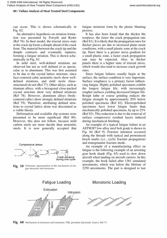
Fig. 58 Schematic illustration of simple fatigue failures
Overview of the Mechanisms of Failure in Heat Treated Steel Components / 79
Name ///sr-nova/Dclabs_wip/Failure_Analysis/5113_43-86.pdf/Chap_02/ 18/8/2008 2:57PM Plate # 0 pg 79
© 2008 ASM International. All Rights Reserved. Failure Analysis of Heat Treated Steel Component (#05113G) www.asminternational.org

can occur. This is shown schematically inFig. 62.
An alternative hypothesis on striation forma-tion was presented by Forsyth and Ryder(Ref 76). In their model, the triaxial stress stateat the crack tip forms a dimple ahead of the crackfront. The material between the crack tip and thedimple contracts and eventually ruptures,forming a fatigue striation. This is shown sche-matically in Fig. 63.
In mild steel, well-defined striations areobserved but not as well defined or as specta-cular as in aluminum. This was first assumedto be due to the crystal lattice structure, sinceface-centered cubic austenitic steels show well-defined striations, and mild steels (base-structured) do not (Ref 77). Other alloys, such astitanium alloys, with a hexagonal close-packedcrystal structure show very defined striations(Ref 78). However, aluminum alloys (body-centered cubic) show strongly defined striations(Ref 79). Therefore, attributing defined stria-tions to crystal lattice alone was discounted asa viable theory.
Deformation and available slip systems werepresumed to be more significant (Ref 80).However, this does not follow, because mildcarbon steels are more ductile than austeniticsteels. It is now generally accepted that
fatigue striations form by the plastic bluntingprocess.
It has also been found that the thicker thetestpiece, the faster the crack propagation rate(Ref 81). It is likely that the propagation rates forthicker pieces are due to increased plane-strainconditions, with a small plastic zone at the cracktip. Since there is a greater stress gradient fora small plastic zone, a faster crack propagationrate may be expected. Also, in thickerpanels there is a higher state of triaxial stress,which would also tend to increase crack growthrates.
Since fatigue failures usually begin at thesurface, the surface condition is very important.Surface roughness is a primary factor influen-cing fatigue. Highly polished specimens exhibitthe longest fatigue life, with increasinglyrougher surfaces yielding decreased fatigue life.Rough lathe or coarse grinding reduces thefatigue strength by approximately 20% belowpolished specimens (Ref 82). Electropolishedspecimens have lower fatigue limits thanmechanically polished specimens, by up to 25%(Ref 83). This reduction is due to the removal ofsurface compressive residual layers inducedduring mechanical finishing.
An example of a typical fatigue failure in anASTM B7 low-alloy steel bolt grade is shown inFig. 64 (Ref 9). Fracture initiation occurredalong the threads with typical and pronouncedbeach marks (i.e., cyclic fracture propagation)and transgranular fracture mode.
An example of a manufacturing effect onfatigue is the following example of an arrestinggear hook shank (Fig. 65) used to slow downaircraft when landing on aircraft carriers. In thisexample, the hook failed after 1361 simulatedarrestments, which was below the lifetime of2250 arrestments. The part is designed to last
Fig. 59 Schematic representation of the mechanism of fati-gue intrusions and extrusions
Fig. 60 Mechanism of intrusions and extrusions. PSB, persistent slip bands. Source: Ref 74
80 / Failure Analysis of Heat Treated Steel Components
Name ///sr-nova/Dclabs_wip/Failure_Analysis/5113_43-86.pdf/Chap_02/ 18/8/2008 2:57PM Plate # 0 pg 80
© 2008 ASM International. All Rights Reserved. Failure Analysis of Heat Treated Steel Component (#05113G) www.asminternational.org

two lifetimes, or 4500 arrestments, withoutcracking (0.25 mm, or 0.010 in. detectibleflaw). The arresting shank was fatigue tested in afixture, with hydraulic cylinders providing loadsat the vertical damper and hook-point cablegroove. The maximum applied load was 90 mg(200,000 lb). A schematic of the arresting hookshank is shown in Fig. 65.
The arresting hook shank was fabricated froman AerMet 100 rotary forging. It is rough turnedon a lathe on the outside, then gun drilled tocreate a pilot hole down the length of the for-ging. The outer surface is turned to the final
diameter. The bore is then injection drilled to thefinal dimensions. A follower supported theinjection drill. This is not a method that iscommonly used for final machining operations.It is heat treated in vacuum to 1930 MPa(280 ksi) ultimate tensile strength. The part isinspected using dye-penetrant and magneticparticle nondestructive testing methods. Thebore is visually inspected using a bore scope.This is a difficult inspection because of the longlength and narrow bore.
Examination of the fracture surface showedthat cracking initiated at the hook-point side,on the inner diameter, at a location approxi-mately 26.5 cm (10.5 in.) aft of the uplockretainer. The fracture had characteristics offatigue fracture, with multiple origins observed.Surface roughness measurements varied acrossthe inner bore, from approximately 1 to 5 mm(40 to 180 min.). The drawing requirement was3 mm (125 min.). Circumferential machiningmarks were found at the fracture origin(Fig. 66). SEM examination (Fig. 67) showedfatigue striations emanating away from theidentified origin. Cracking was found to haveinitiated at circumferential machining marks.Machining marks were observed at 4.3 mm(0.17 in.) intervals. Many secondary crackswere observed at the machining marks. Fatiguewas found to initiate subsurface to the innerbore, adjacent to the machining marks. A well-defined surface layer was observed. This layerhad the appearance of mechanical working ordamage. This observed layer followed the feedsand speeds of the injection drill. Metallographyshowed that the material was quenched andtempered martensite and was typical for thismaterial heat treated to this hardness. At the
Fig. 62 Mechanism for fatigue striation formation
Fig. 61 Typical fatigue striations in 7075 aluminum
Fig. 63 Striation formation from ductile dimple formationahead of a crack front
Overview of the Mechanisms of Failure in Heat Treated Steel Components / 81
Name ///sr-nova/Dclabs_wip/Failure_Analysis/5113_43-86.pdf/Chap_02/ 18/8/2008 2:57PM Plate # 0 pg 81
© 2008 ASM International. All Rights Reserved. Failure Analysis of Heat Treated Steel Component (#05113G) www.asminternational.org

origin, the presence of well-defined subsurfacecracking was observed. This layer had theappearance of smeared metal and base metalpullout. Flat cracking, suggestive of fatiguecracking, was observed to emanate from theflaw (Fig. 68). The flaws were located at4.3 mm (0.017 in.) intervals, identical to thefeed rate of the injection drilling process.
During the injection drilling process, threecutters are used. Coolant is forced through acentral hole to cool the cutting tools and to flushthe chips. AerMet 100 tends to form long strandsof material during machining and does not wantto form chips. Hot chips can contact the freshlymachined surface. These chips or long strandsare under pressure at the cutter or followerand can be forced onto the newly machinedsurface by the follower. If the temperature andpressures are high enough, solid-state welding ofthe chips and bore surface can occur. As thecutter boring bar moves, pullout can occur. The
Fig. 64 ASTM B7 low-alloy steel bolt grade. Fracture initiated along threads, with typical and pronounced beach marks (i.e., cyclicfracture propagation) and transgranular fracture mode. (a) Location of bolts in pump coupling. (b) Beach marks showing
asymmetrical bending with initiation at high stress-concentration factor at bolt threads. (c) Transgranular fracture morphology
Fig. 65 Schematic of the failed arresting hook shank showing location of loads
Fig. 66 Machining marks found on the inside of the bore, atthe origin of cracking
82 / Failure Analysis of Heat Treated Steel Components
Name ///sr-nova/Dclabs_wip/Failure_Analysis/5113_43-86.pdf/Chap_02/ 18/8/2008 2:57PM Plate # 0 pg 82
© 2008 ASM International. All Rights Reserved. Failure Analysis of Heat Treated Steel Component (#05113G) www.asminternational.org

examined flaws matched the machining feedsand speeds.
The arresting hook failed by fatigue,initiating at flaws created during the finalmachining process. The defect morphologysuggested localized solid-state welding andpullout from chip contact with the freshlymachined surface. The surface roughness andfinish of the inner bore did not meet drawingrequirements.
Summary
In this short overview of the possiblemechanisms of failure for steels, the followingwere discussed:
� Techniques for examining fractures� Ductile and brittle failures� Intergranular failure mechanisms� Fatigue
The previous discussion has shown that it isimportant to look at not only the fracture surfacebut at all the factors (manufacturing history,service conditions, and loading). All the toolsavailable to the metallurgist should be used—these include photography, fractography, and
Fig. 67 SEM examination of the fracture surface. (a) Fatiguestriations emanating from the fracture origin. (b)
Machining marks found on the surface of the inner bore. (c) Well-defined layer showing fatigue emanating from the damagedmaterial at the surface of the inner bore
Fig. 68 Metallography of the arresting hook shank. (a) Typi-cal quenched and temperedmartensite found. This is
typical for the hardness of the arresting hook shank. (b) Pulledmaterial at 4.3 mm (0.17 in.) intervals along the inner bore of thearresting hook shank. Origin is to the left. (c) Secondary crackingobserved at the location of pulled material
Overview of the Mechanisms of Failure in Heat Treated Steel Components / 83
Name ///sr-nova/Dclabs_wip/Failure_Analysis/5113_43-86.pdf/Chap_02/ 18/8/2008 2:57PM Plate # 0 pg 83
© 2008 ASM International. All Rights Reserved. Failure Analysis of Heat Treated Steel Component (#05113G) www.asminternational.org

metallography—to understand the sources androot cause of failure.
REFERENCES
1. Hippocrates, Epidemics, Book I, Section XI2. D.S. MacKenzie, G. Chen, M. Barker,
C. Ramsay, J. Alderson, L. Dharani, andJ. Yu, Forensic Investigation of Failed MastArms of Traffic Signal Supported Struc-tures, Transport. Res. Record, Des. Struc.2002, 2002, p 9–16
3. “Loss of Control and Impact with PacificOcean Alaska Airlines Flight 261 McDon-nell Douglas MD-83, N963AS about 2.7Miles North of Anacapa Island, California,January 31, 2000,” NTSB/AAR-02/01,National Transportation Safety Board,Adopted Dec 30, 2002, Notation 7263E
4. “Uncontained Engine Failure/Fire ValujetAirlines Flight 597 Douglas DC-9-32,N908VJ, Atlanta, Georgia, June 8, 1995,”NTSB/AAR-96/03, National Transporta-tion Safety Board, Adopted July 30, 1996,Notation 6579A
5. W.M. Garrison and N.R. Moody, J. Phys.Chem. Solids, Vol 48, 1987 p 1035
6. J.F. Knott, Advances in Fracture Research,Proc. Seventh International Conference onFracture (Oxford, U.K.) 1989, p 125
7. J.F. Knott, Fracture 1977, Vol 1, Proc.Fourth International Conference on Frac-ture, June 1977 (Waterloo Canada), p 61
8. H.G. Wilsforf, Mater. Sci. Eng., Vol 59,1983, p 1
9. B. Bøgner, G. Rørvik, and L. Marken, BoltFailures—Case Histories from the Nor-wegianPetroleumIndustry,Microsc. Micro-anal., Vol 11 (Suppl. 2), 2005, p 1604–1605
10. T.L. Anderson, Fracture Mechanics, CRCPress, New York, 1995
11. C. Ruggieri, Numerical Investigation ofConstraint Effects on Ductile Fracture inTensile Specimens, J. Braz. Soc. Mech. Sci.Eng., Vol 26 (No. 2), 2004
12. “Standard Test Methods for Determiningthe Inclusion Content of Steel,” E45–05,ASTM International
13. “Premium Aircraft-Quality Steel Clean-liness: Magnetic Particle Inspection Proce-dure,” AMS 2300
14. “Aircraft-Quality Steel Cleanliness:Magnetic Particle Inspection Procedure,”AMS 2301
15. “Aircraft-Quality Steel Cleanliness: Mart-ensitic Corrosion-Resistant Steels MagneticParticle Inspection Procedure,” AMS 2303
16. “Special Aircraft-Quality Steel Cleanliness:Magnetic Particle Inspection Procedure,”AMS 2304
17. R. Kiessling and N. Lange, Non-MetallicInclusions in Steel, Part I–IV, Iron and SteelInstitute, London, 1978
18. S. Maropoulos and N. Ridley, Inclusionsand Fracture Characteristics of HSLA SteelForgings, Mater. Sci. Eng. A, Vol 384 (No.1–2), Oct 25, 2004, p 64–69
19. “Railway Investigation Report, Derailmentand Collision Canadian National TrainNo. U-783-21-30 and Train No. M-306-31-30Mile 50.84, Saint-Hyacinthe SubdivisionMont-Saint-Hilaire, Quebec, December 301999,” Report R99H0010, TransportationSafety Board of Canada
20. M.L. Williams, STP 158, ASTM, 1954,p 11–44
21. M.E. Shank, STP 158, ASTM, 1954, p45–110
22. Fractography, Vol 12, Metals Handbook,9th ed., ASM International, 1987
23. J. McCall and P. French, Metallography inFailure Analysis, Plenum, New York, 1978,p 6
24. “Standard Test Methods for NotchedBar Impact Testing of Metallic Methods,”E23–88, American Society for Testing andMaterials
25. “Standard Test Method for Plane StrainFracture Toughness, KIc, of Metallic Mate-rials,” E399–74, American Society forTesting and Materials
26. “Standard Test Method for ConductingDrop-Weight Test to Determine Nil-Ductility Transition Temperature of FerriticSteels,” E208–95A, American Society forTesting and Materials, 1983
27. “Standard Test Method for Dynamic TearTesting of Metallic Materials,” E604–83,American Society for Testing and Materi-als, 1983
28. J.M. Kraft, A.M. Sullivan, and R.W. Boyle,Proc. Symp. Crack Propagation, Cranfield,U.K., 1961
29. W.F. Brown and J.E. Strawley, STP 381,American Society for Testing and Materi-als, 1965, p 133
30. A.S. Tetelman and A.J. McEvily, Fractureof Structural Materials, Wiley, New York,1967
84 / Failure Analysis of Heat Treated Steel Components
Name ///sr-nova/Dclabs_wip/Failure_Analysis/5113_43-86.pdf/Chap_02/ 18/8/2008 2:57PM Plate # 0 pg 84
© 2008 ASM International. All Rights Reserved. Failure Analysis of Heat Treated Steel Component (#05113G) www.asminternational.org
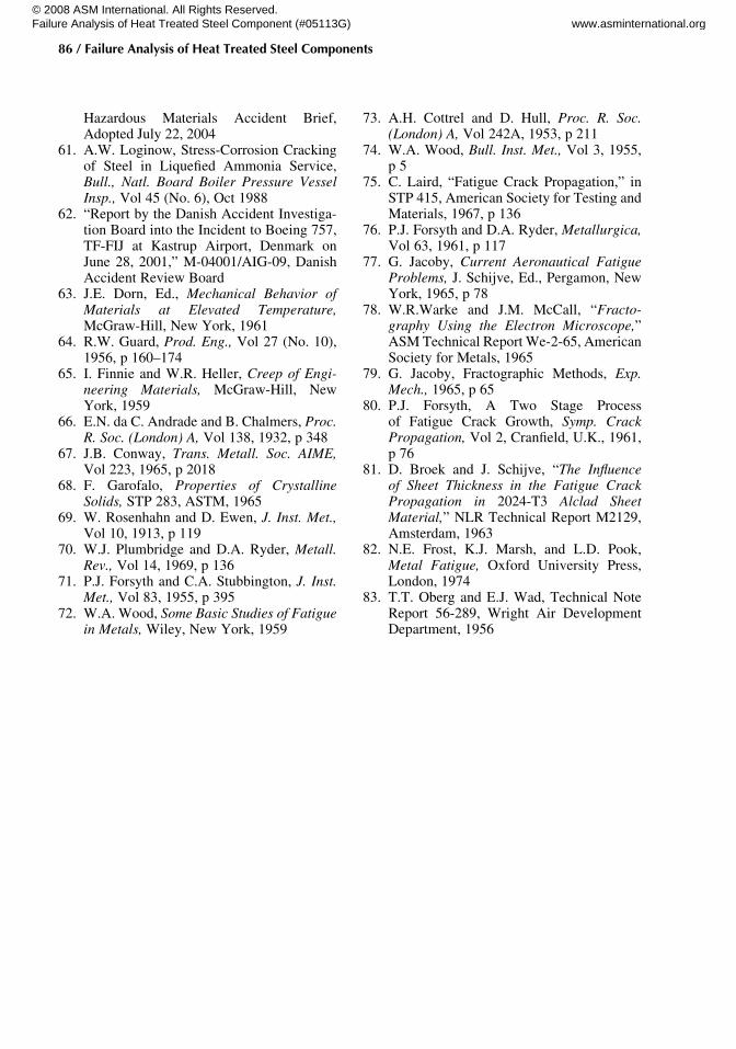
31. J.F. Knott, Fundamentals of FractureMechanics, Wiley, New York, 1973
32. A.H. Cottrell, Proc. R. Soc. A, Vol 276(No. 1), 1963
33. A.H. Knott, Mater. Sci. Eng., Vol 7 (No. 1),1971
34. J.S. Colton, Class notes, “Great BostonMolasses Disaster, Jan 15, 1919,” ME6222Manufacturing Processes and Systems,Georgia Institute of Technology
35. G. Krauss, Steels: Heat Treatment andProcessing Principles, ASM International,1990, p 231, 237
36. G. Thomas, Retained Austenite and Tem-pered Martensite Embrittlement, Metall.Trans. A, Vol 10, 1979, p 1643–1651
37. S. Banerji, C. McMahon, and H.Feng, Intergranular Fracture in 4340-Type Steels: Effects of Impurities andHydrogen, Metall. Trans. A, Vol 9, 1978,p 237–247
38. D. Kalderon, Steam Turbine Failure atHinkley Point ‘A’, Proc. Inst. Mech. Eng.,Vol 186, 1972, p 341–377
39. L.D. Kramer and D. Randolph, Analysisof TVA Gallatin No. 2 Rotor Burst: Part1—Metallurgical Considerations, Proc.1976 ASME-MPC Symposium on Creep-Fatigue Interaction, p 1–24
40. H.K.D.H. Bhadeshia, High PerformanceBainitic Steels, Mater. Sci. Forum, Vol 500,2005, p 63–74
41. I. Olefjord, Temper Embrittlement, Re-view 231, Int. Met. Rev., Vol 23, 1978, p149–163
42. B.Woodfine, Temper Brittleness, A CriticalReview of the Literature, JISI, Vol 173,1953, p 229–240
43. F. Carr, M. Golman, L. Jaffee, and D. Buf-fum, Isothermal Temper Embrittlement ofSAE 3140 Steel, Trans. TMS-AIME, Vol197, 1953, p 998
44. Liquid Metal Embrittlement, Failure Ana-lysis and Prevention, Vol 10, MetalsHandbook, 8th Ed., American Society forMetals, 1975, p 228–229
45. P. Fernandez, R. Clegg, and D. Jones,Failure by Liquid Metal Induced Embrit-tlement, Eng. Fail. Anal., Vol 1 (No. 1),1994, p 51–63
46. G. Vilganlte, G. Troiano, and C. Mossey,“Liquid Metal Embrittlement of ASTMA723 Gun Steel by Indium and Gallium,”ARCCB-TR-99011, Army Research,Development and Development Center,
Benet Laboratories, Watervliet Arsenal,June 1999
47. NTSB CHI97IA117, National Trans-portation Safety Board, adopted June 28,1998
48. NTSB Safety Recommendation, in memo toJ. Garvy, Administrator A-97-83, FAA,Aug 29, 1997
49. S.F. Carter, Effect of Melting Practice onHydrogen, J. Met. (AIME), Vol 188,Jan 1950, p 30–40 and J. Met. (AIME), Vol188, Feb 1950, p 245–255
50. F.B. Foley, Flakes and Cooling Cracksin Forgings, Met. Alloys, Vol 12, 1940,p 442–445
51. F.J. Shortsleeve and A.R. Troiano, “A Lit-erature Survey on the Mechanism of FlakeFormation,” Interim Technical Report 1,Contract DA 33-019-ORD-897
52. C.A. Edwards, Pickling or the Actionof Acid Solution on Mild Steel and theDiffusion of Hydrogen Through the Metal,J. Iron Steel Inst., Vol 110, 1924, p 9–60
53. C.A. Zapffe and M.E. Haslem, Acid Com-position, Concentration Temperature andPickling Time as Factors in the HydrogenEmbrittlement of Mild Steel and StainlessSteel Wire, Trans. ASM, Vol 39, 1947,p 213–236
54. J.R. Gustafson, Some of the Effects ofCadmium, Zinc, and Tin Plating on Springs,Proc. ASTM, Vol 47, 1947, p 782
55. K.B. Valentine, Stress Cracking ofElectroplated Lockwashers, Trans. ASM,Vol 38, 1947, p 488–504
56. C.A. Zapffe and M.E. Haslem, Measure-ment of Embrittlement during Chromiumand Cadmium Electroplating and the Natureof Recovery of Plated Articles, Trans. ASM,Vol 39, 1947, p 241–258
57. G. Nagu and T. Namboodhiri, Effect ofHeat Treatments on the Hydrogen Embrit-tlement Susceptibility of API X-65 GradeLine-Pipe Steel, Bull. Mater. Sci., Vol 26(No. 4), June 2003, p 435–439
58. A. Thompson and I. Berstein, Ed., Effectof Hydrogen on Behavior of Materials,TMS-AIME, 1976
59. H. Johnson, J. Morlet, and A. Troiano,Hydrogen Crack Initiation and DelayedFailure in Steel, Trans. TMS-AIME, Vol212, 1958, p 528–536
60. “Release of Hazardous Materials fromCargoTank inMiddletown,Ohio, onAugust22, 2003,” Accident DCA03MZ002, NTSB
Overview of the Mechanisms of Failure in Heat Treated Steel Components / 85
Name ///sr-nova/Dclabs_wip/Failure_Analysis/5113_43-86.pdf/Chap_02/ 18/8/2008 2:57PM Plate # 0 pg 85
© 2008 ASM International. All Rights Reserved. Failure Analysis of Heat Treated Steel Component (#05113G) www.asminternational.org

Hazardous Materials Accident Brief,Adopted July 22, 2004
61. A.W. Loginow, Stress-Corrosion Crackingof Steel in Liquefied Ammonia Service,Bull., Natl. Board Boiler Pressure VesselInsp., Vol 45 (No. 6), Oct 1988
62. “Report by the Danish Accident Investiga-tion Board into the Incident to Boeing 757,TF-FIJ at Kastrup Airport, Denmark onJune 28, 2001,” M-04001/AIG-09, DanishAccident Review Board
63. J.E. Dorn, Ed., Mechanical Behavior ofMaterials at Elevated Temperature,McGraw-Hill, New York, 1961
64. R.W. Guard, Prod. Eng., Vol 27 (No. 10),1956, p 160–174
65. I. Finnie and W.R. Heller, Creep of Engi-neering Materials, McGraw-Hill, NewYork, 1959
66. E.N. da C. Andrade and B. Chalmers, Proc.R. Soc. (London) A, Vol 138, 1932, p 348
67. J.B. Conway, Trans. Metall. Soc. AIME,Vol 223, 1965, p 2018
68. F. Garofalo, Properties of CrystallineSolids, STP 283, ASTM, 1965
69. W. Rosenhahn and D. Ewen, J. Inst. Met.,Vol 10, 1913, p 119
70. W.J. Plumbridge and D.A. Ryder, Metall.Rev., Vol 14, 1969, p 136
71. P.J. Forsyth and C.A. Stubbington, J. Inst.Met., Vol 83, 1955, p 395
72. W.A. Wood, Some Basic Studies of Fatiguein Metals, Wiley, New York, 1959
73. A.H. Cottrel and D. Hull, Proc. R. Soc.(London) A, Vol 242A, 1953, p 211
74. W.A. Wood, Bull. Inst. Met., Vol 3, 1955,p 5
75. C. Laird, “Fatigue Crack Propagation,” inSTP 415, American Society for Testing andMaterials, 1967, p 136
76. P.J. Forsyth and D.A. Ryder, Metallurgica,Vol 63, 1961, p 117
77. G. Jacoby, Current Aeronautical FatigueProblems, J. Schijve, Ed., Pergamon, NewYork, 1965, p 78
78. W.R.Warke and J.M. McCall, “Fracto-graphy Using the Electron Microscope,”ASM Technical Report We-2-65, AmericanSociety for Metals, 1965
79. G. Jacoby, Fractographic Methods, Exp.Mech., 1965, p 65
80. P.J. Forsyth, A Two Stage Processof Fatigue Crack Growth, Symp. CrackPropagation, Vol 2, Cranfield, U.K., 1961,p 76
81. D. Broek and J. Schijve, “The Influenceof Sheet Thickness in the Fatigue CrackPropagation in 2024-T3 Alclad SheetMaterial,” NLR Technical Report M2129,Amsterdam, 1963
82. N.E. Frost, K.J. Marsh, and L.D. Pook,Metal Fatigue, Oxford University Press,London, 1974
83. T.T. Oberg and E.J. Wad, Technical NoteReport 56-289, Wright Air DevelopmentDepartment, 1956
86 / Failure Analysis of Heat Treated Steel Components
Name ///sr-nova/Dclabs_wip/Failure_Analysis/5113_43-86.pdf/Chap_02/ 18/8/2008 2:57PM Plate # 0 pg 86
© 2008 ASM International. All Rights Reserved. Failure Analysis of Heat Treated Steel Component (#05113G) www.asminternational.org

ASM International is the society for materials engineers and scientists, a worldwide network dedicated to advancing industry, technology, and applications of metals and materials. ASM International, Materials Park, Ohio, USA www.asminternational.org
This publication is copyright © ASM International®. All rights reserved.
Publication title Product code Failure Analysis of Heat Treated Steel Components 05113G
To order products from ASM International:
Online Visit www.asminternational.org/bookstore
Telephone 1-800-336-5152 (US) or 1-440-338-5151 (Outside US) Fax 1-440-338-4634
Mail Customer Service, ASM International 9639 Kinsman Rd, Materials Park, Ohio 44073-0002, USA
Email [email protected]
In Europe
American Technical Publishers Ltd. 27-29 Knowl Piece, Wilbury Way, Hitchin Hertfordshire SG4 0SX, United Kingdom Telephone: 01462 437933 (account holders), 01462 431525 (credit card) www.ameritech.co.uk
In Japan Neutrino Inc. Takahashi Bldg., 44-3 Fuda 1-chome, Chofu-Shi, Tokyo 182 Japan Telephone: 81 (0) 424 84 5550
Terms of Use. This publication is being made available in PDF format as a benefit to members and customers of ASM International. You may download and print a copy of this publication for your personal use only. Other use and distribution is prohibited without the express written permission of ASM International. No warranties, express or implied, including, without limitation, warranties of merchantability or fitness for a particular purpose, are given in connection with this publication. Although this information is believed to be accurate by ASM, ASM cannot guarantee that favorable results will be obtained from the use of this publication alone. This publication is intended for use by persons having technical skill, at their sole discretion and risk. Since the conditions of product or material use are outside of ASM's control, ASM assumes no liability or obligation in connection with any use of this information. As with any material, evaluation of the material under end-use conditions prior to specification is essential. Therefore, specific testing under actual conditions is recommended. Nothing contained in this publication shall be construed as a grant of any right of manufacture, sale, use, or reproduction, in connection with any method, process, apparatus, product, composition, or system, whether or not covered by letters patent, copyright, or trademark, and nothing contained in this publication shall be construed as a defense against any alleged infringement of letters patent, copyright, or trademark, or as a defense against liability for such infringement.