Embed Size (px)
Citation preview

Overview on in-Vivo Verification,
including 4D Capabilities
4D Treatment Planning Workshop 2015 Dresden, November 27, 2015
Wolfgang Enghardt
OncoRay – National Center for Radiation Research in OncologyTechnische Universität Dresden, Germany
University Hospital Carl Gustav Carus Dresden, GermanyDept. of Radiation Therapy
Helmholtz-Zentrum Dresden-Rossendorf, Dresden, GermanyInstitute of Radiooncology

Outline
1. State of the art
2. In-room imaging: X-rays
3. Magnetic resonance imaging and radiotherapy
4. Particle beams: The in-vivo range problem
5. Summary

Obtain exact knowledge on
- patient position- anatomy
in real time during dose delivery for
- reducing treatment margins
- interactive adaption of treatment on the basis of daily• assessment of changes in tumour volume• general response to therapy (e.g. loss of weight)
D. Verellen et al.: Nature Reviews Cancer 7 (2007) 949 C. Gillham et al. Radiother. Oncol. 88 (2008) 335
PET PET • Tumour volumereduction: 49.2 %
• Potential fortumour dose escalation
Before treatment
1. State of the artRequirements to in-room imaging
After dose delivery of 50 Gy

The sniperThe observer
US Marine Corps, ID 001117-M-OW241-002
is blind is outstanding
1. State of the artRadiation therapy and imaging: The situation before 2000
What you do not see, you cannot hit, and what you do not hit, you cannot cure. Wolfgang Schlegel, DKFZ Heidelberg

1. State of the artCT: Spatial and time resolution
� 64 … 320 detector rows (2 × 192)
� Slice thickness 0.33 … 0.6 mm
� In-plane resolution: ≤ 2.3 lp/mm, pixel: 0.22 mm (0.24 mm)
� Tube rotation time ≥ 0.25 s, time resolution ≥ 66 ms
dual source (180° → 90°), two 120 kW generators
� Volume coverage with one rotation: 4 … 16 cm
� Maximum scan speed: 730 mm/s
www.healthcare.siemens.com/computed-tomography/computed-tomography/, Med. Faculty Mannheim at Heidelberg University
Example: Thoracicimaging w/o breathhold(dyspnea)� Scan time: 0.7 s� Rotation time: 0.25 s� Scan length: 294 mm� Spatial resol.: 0.24 mm� Eff. dose: 1.2 mSv

1. State of the artMR: Soft tissue contrast and function
www.healthcare.philips.com/main/products/mri/..., www.healthcare.siemens.com/computed-tomography/computed-tomography/...
� B ≤ 3 T
� Imaging volume: axial: ≤ 400 mm, transax: ≤ 550 mm
� Slice thickness: ≥ 0.3 mm
� In-plane resolution, pixel: 0.5 mm
� Time resolution: ≥ 10 ms(single planes, MR “fluoroscopy“)
� Time and spatialresolution at MRI:SNR dependent(5 µm in plane)
MRI: mDiXONsequence36 s
CT: 727 mm scan1.44 s
BonemetastasesDWIBS4.5 × 4.7 × 5.0 mm3

The problem of daily patient positioning is multiplied by target movement
Intrafractional Interfractional
M. van Herk et al., Netherlands Cancer Institute, Amsterdam, NLF. Pönisch et al., OncoRay, Dresden, Germany
Reduce the errors means:Imaging, imaging, imaging, but how?
Challenge: precise positioning over ~ 30 daily fractions
2. In-room imaging: X-raysPatient positioning: steep dose gradients, selective RBE

e--linac
MV cone beam CT
In-r
oom
CT
on r
ails
kV X-rayposition control,
flouroscopy
IR m
ovem
ent
trackin
g
Radiotherapy Department,University Hospital Dresden
2. In-room imaging: X-raysElectron linacs – state of the art in IGRT
Radiotherapy J. Distler,Bautzen
kV cone beam CT

Planning CT
CT after 2 w. RT
Chordoma, 12C, GSI Darmstadt
W. Enghardt et al.: Radiother. Oncol 73 (2004) S96
2. In-room imaging: X-raysError sensitivity of particle therapy: The Lomax (Di)Lemma
Photons: Ultrahard (15 MV) bremsstrahlung
Protons: 90–120 MeV
2 4 6 8 10 120
20
40
60
80
100
Rela
tive e
ffektive D
ose / %
Penetration depth in water / cm
*Tony Lomax, Paul Scherrer Institut, Villigen, CH:
The biggest advantage of protons is that they stop.
The biggest disadvantage of protons isthat we do not always know where they stop.

2. In-room imaging: X-raysIGRT at particle facilities
Orthogonal planarX-ray imaging
Present situation(2014)
UPTD HIT
New developments(2014)
UPTDIBA
kV CBCT at the gantry
CT on rails in thetreatment room

2. In-room imaging: X-raysDose considerations (I)
R.A. Hälg et al.: Med. Phys. 39 (2012) 7650-7661, M.J. Murphy et al.: Med. Phys. 34 (2007) 4041-4063
IGRT dose values outside the target relative to scatter- and leakage doseDleakage ≤ 0.2 % Dtarget, NCRP 102 (1989), Dleakage ≤ 4 mSv/fraction :
• Treatment planning (3D CT): 1 %
• Treatment planning (4D CT): 10 %
• CBCT (kV, MV): 5 – 30 %
• EPID (MV): 3 – 25 %
• Tomotherapy MV-CT: < 1 %
• Planar kV-radiography: < 1 %
Image based motion compensation:
• Breathing period: 6 s
• CT sampling frequency: 1/3 Hz
• Irradiation time: 2 min for 2 Gy
• Effective dose per fraction: 48 mSv
• Total effective dose per treatment:1.5 Sv
Example: Thoracicimaging w/o breathhold(dyspnea)� Scan time: 0.7 s� Eff. dose: 1.2 mSv
�
CT-Linac
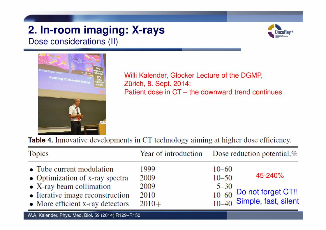
2. In-room imaging: X-raysDose considerations (II)
W.A. Kalender. Phys. Med. Biol. 59 (2014) R129–R150
Willi Kalender, Glocker Lecture of the DGMP,Zürich, 8. Sept. 2014:Patient dose in CT – the downward trend continues
Do not forget CT!!Simple, fast, silent
45-240%

3. MRI and RTReal-time MRI
… with an ordinary 1.5 T MRI scanner: time resolution 643 ms
Single plane imaging, not volumetric
Courtesy: N. Abolmaali, OncoRay Dresden

3. MRI and RTThe MRI-Linac: The Utrecht approach
University Medical Center, Utrecht, NLPhilips Research, Hamburg, GERElekta Oncology Systems, Crawley, UKRaySearch Laboratories, Stockholm, S
Apr. 5, 2014: Start of 1st clinical installationAt University Medical Center, Utrecht, NL
B.W.Raaymakers et al.: PMB 56 (2011) N207; B.W.Raaymakers et al.: PMB 54 (2009) N229, Courtesy: J. Lagendijk
6 M
V lin
ac
1.5
T d
iagnostic M
RI

3. MRI and RTMRI combined with an 60Co source: The ViewRay approach
ViewRay, Inc. Gainsville . FL , www.viewray.com, C. Fox et al.: Phys. Med. Biol. 53 (2008) 3175
Prostate: 7 beams, dose distributions• 0,35 T split magnet MRI scanner
• 3 sources of 60Co: - 500 TBq 750 cGy/min.- avoids RF interference
• Adaptive treatment planning
• Motion management
60Co6 MV

4. Particle beams: The in-vivo range problemNuclear methods for range assessment: Overview
1. Positron emitting radionuclides (15O, 14O, 11C, 10C)Particle Therapy Positron Emission Tomography (PT-PET)
2. Prompt γ-raysPrompt γ-ray imaging (PGI)Prompt γ-ray timing (PGT)Prompt γ-ray spectroscopy (PGS)
3. Light charged particlesInteraction vertex imaging (IVI)
Nucleons
and clusters
Projectile
Target
Projectile fragment
Target fragment
Fireball
Prompt γ-rays
Radioactive
nuclides
K. Gunzert-Marx, et al.: New J. Phys. 10 (2008) 075003
Nuclear reactions: an unavoidable byproduct of particle therapy

52
4. Particle beams: The in-vivo range problemThe time scales
Time after collision/s
10-21 10-18 10-15 10-12 10-9 10-6 10-3 100 103
Particles
Prompt γ-rays
β+-decay
Nucleons
and clusters
Projectile
Target
Projectile fragment
Target fragment
Fireball
Prompt γ-rays
Radioactive
nuclides
Consequences:
1. Washout: No No Yes
2. Signal (motion)Time tprod ≈ tmeas tprod ≈ tmeas tprod << tmeas
Localization rprod ≈ rmeas rprod ≈ rmeas rprod ≠ rmeas (4D!)

4. Particle beams: The in-vivo range problemβ+-emitting radionuclides
J. Pawelke et al.: PMB 1996; W. Enghardt et al.: NIM A 2004; K. Parodi et al.: IJROBP 2007; C.H. Min et al.: IJROBP 2013
In-beam: GSI In-room: MGH Off-line: HITFurther:
• Univ. of Florida• HIMAC, Chiba, J• NCC, Kashiwa, J • HIBMC, Hyogo, J• MDACC, Houston• CNAO, Pavia
• Technology: �
• Research: Clinical appl.Moving targets
Nucleons
and clusters
Projectile
Target
Projectile fragment
Target fragment
Fireball
Prompt γ-rays
Radioactive
nuclides

4. Particle beams: The in-vivo range problemPrompt γ-rays
Nucleonsand clusters
Prompt γ-rays
Pro
mpt
γ-ra
yim
agin
g(p
assiv
e c
olli
mation)
Pro
mpt
γ-ra
ytim
ing
Decreasing complexity
T. Kormoll et al.: NIM A 2011; J. Verburg et al.: PMB 2014; J. Smeets et al.: PMB 2012, C. Golnik et al.: PMB 2014
Pro
mpt
γ-ra
yim
agin
g(e
lectr
onic
colli
mation)

4. Particle beams: The in-vivo range problemLight charged particles
Nucleonsand clusters
Prompt γ-rays
E. Haettner: M.Sc. Thesis, KTH Stockholm, 2006; P. Henriquet et al.: PMB 2012; M. Martisikova, 2012 IEEE NSS/MIC, N37-4
12C: E = 400 AMeV
R = 27.5 g/cm2
on water
Interaction vertex imaging:
, θ = 0°
( )
( )cm 40
MeV 260
MeV 260
≈
= AR
Rp
α
Ion beam
PSD
+ High detection efficiency ofcharged particles
- Beam position has to be known
- Light charged particles are forwarddirected ⇒ inferior range resolution
- Not applicable to proton beams
°≈∆
°=
5
0
FWHMθ
θ

4. Particle beams: The in-vivo range problemGeneral workflow of nuclear range assessment methods
W. Enghardt et al.: Radiother. Oncol. 2004; F. Pönisch et al.: PMB 2004; K. Stützer: Thesis, TU Dresden, 2013
Dose
Monte Carlo
β+-activity
β+-activityDose
Evaluation, reaction
Moving targets: 4D-CT (TP, Monte Carlo); motion tracking (irradiation and measurement);PBS: beam recording (time and localization)

5. Summary
„Linear accelerators produce radiation distributions which are only slightly better than60Co. They are complicated and require back up services of well trained technicians orphysicists. Their increased complexity over 60Co will prevent them from beinguniversally accepted.“In H.E. Johns, J.R. Cunningham (1971) Physics of Radiology,3rd ed., Thomas, Springfield, IL
• Real-time IGRT will be the future in RT:integration of irradiation and imaging
• X-ray IGRT delivers additional doseoutside the target volume
• The basis of future real time IGRT will bemagnetic resonance imaging
• Particle therapy requires range control:- in-beam PET- prompt γ-ray imaging- prompt γ-ray spectroscopy- prompt γ-ray timing

Thank you