Embed Size (px)
Citation preview

Overview of the current TDR system
• Introduction• Electronics for instrumentation• TDR core : Metronome, ADC, Merge• Data Handling
Pete Jones, University of JyväskyläSAGE / LISA Kick-Off Meeting
Daresbury Laboratory, 2nd September 2005

TDR(Total Data Readout)
• Collects data from all detectors (over 500 channels and timestamps arrival to 10ns accuracy) and keeps it synchronised
• Timestamping ADCs : Measure energy + time of arrival of signal.
• All possible data is therefore collected

Electronics• Each detector pre-amp output to electronics racks• Amplifier : TFA / CFD combination – ADC Gate• Amplifier : Shaping amp – ADC input
– Logic signals to user electronics, TACS• 4 free channels (x16) w/o JUROGAM
AMP
CFD
ADC

Electronics• Linear amplifer suffer decreased resolution for counting rates > 3kHz
• CFD/TFA gives good response at counting rates 0-100kHz
• Large number of high count rate spectroscopy channels
AMP
CFD
ADC
AMP
0
50
100
150
200
250
300
350
0 100 200 300 400
Beam Current (enA)
Co
un
t R
ate
Total Ge
Trig Rate
ADC Rate

TDR ADC• VXI Card with 32 independent channels (analogue input + gate)• 14 bit, 0-8V, 4.5us conversion time, sliding-scale : 16k spectra• Flexible gating conditions can be programmed / Veto inputs• Generates timestamp from gate and converts • Output of data via SHARC link• JUROGAM uses 2 cards -> 64 channels available
T1 T2
E
Detect and measure ”pileup” by second pulse : two timestampsFast Decays / Ge pileup - TDR
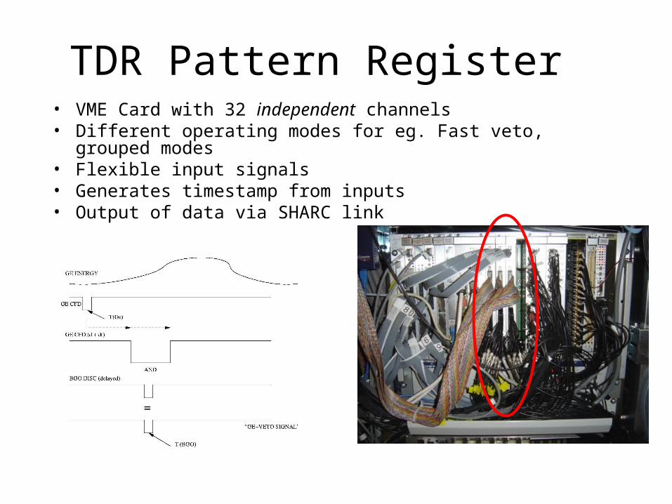
TDR Pattern Register• VME Card with 32 independent channels• Different operating modes for eg. Fast veto, grouped modes• Flexible input signals• Generates timestamp from inputs • Output of data via SHARC link

TDR Metronome• Heart of the TDR system• Master 100MHz clock for ALL TDR components• Generates SYNC pulses (every 655us) + fast starts whole system• Battery backup of clock counter• 8 outputs, currently 3 free
100 MhZ Distribution through cables
SYNC Pulse Distribution

DATA COLLATE
Data from each ADC card is time ordered, but COLLATE these together to produce time ordered data per SHARC & Over all sharcs
ADC
ADC
ADC
SHARC
SHARC
TIME ORDERED DATA

How TDR works : DATA MERGE
Data from all COLLATORS are MERGED together and time ordered.
COLLATOR
COLLATOR
COLLATOR
COLLATOR
MERGE

Collate / Merge• VME Based 3 processor system• Merge CPU takes data from 2 collate CPUs, time orders,
histograms• Output via Gbit ethernet to Event Builder• Processes up to 2Mevents/s, or 16MByte/s

Overview

Event Builder• Once data are correlated by Event Builder, data selections can
be processed in flexible way.• Data can be output to several destinations• Data Selection Reduce raw singles data to useful coincidence
data
GASSi Si2us
JUROGAM PU / BGO supression

Data Storage / Analysis• Selected data (i.e. anything with GREAT) sent to DataStore
– 2TB Raid 1 array + redundancy – accessable from Gbit network
• Data also available by online & offline workstations• User decides how to store data : Disc, Tape, etc.

Overview of the current TDR system
• ~400 channels of electronics• Over 500 channels of analogue / digital inputs into TDR• Stable metronome with master 100MHz clock• VXI / VME based core of acquisition• PC based Merge / Online / Offline systems
• Stable environment for electronics & acquisition
• Extremely stable for experiments, over 3 months continual running without fault