Embed Size (px)
Citation preview

Overview of Packet Capturing Tools in Cisco Switches and Routers
BRKARC-2011
Andy Gossett, Technical Leader, Cisco Services [email protected]
Yogesh Ramdoss, Technical Leader, Cisco Services [email protected]

© 2014 Cisco and/or its affiliates. All rights reserved. BRKARC-2011 Cisco Public
Agenda
• Introduction
• Capturing Packets at the Control Plane
• Capturing Packets at the Data Plane
• Tips and Tricks
• Putting it All Together
• Q&A
3

© 2014 Cisco and/or its affiliates. All rights reserved. BRKARC-2011 Cisco Public
Agenda
• Introduction
• Capturing Packets at the Control Plane
• Capturing Packets at the Data Plane
• Tips and Tricks
• Putting it All Together
• Q&A
4
© 2014 Cisco and/or its affiliates. All rights reserved. BRKARC-2011 Cisco Public
Goal of this Session…
5
Create awareness of the packet capturing tools available in Cisco switching and routing platforms
Provide an overview of these tools, with real-world examples
Discuss how these tools are different from each other in terms of capabilities and functionalities
© 2014 Cisco and/or its affiliates. All rights reserved. BRKARC-2011 Cisco Public
Defining the Problem, Impact, and Scope
6
Choppy
Video
Application
Slowness Call Drops Webpage
Won’t Load
Impact/Scope
Network-Wide Assessment
Problem Isolation
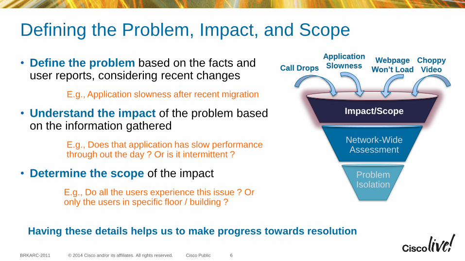
• Define the problem based on the facts and user reports, considering recent changes
E.g., Application slowness after recent migration
• Understand the impact of the problem based on the information gathered
E.g., Does that application has slow performance through out the day ? Or is it intermittent ?
• Determine the scope of the impact
E.g., Do all the users experience this issue ? Or only the users in specific floor / building ?
Having these details helps us to make progress towards resolution
© 2014 Cisco and/or its affiliates. All rights reserved. BRKARC-2011 Cisco Public
Assess the problem at a network-wide level
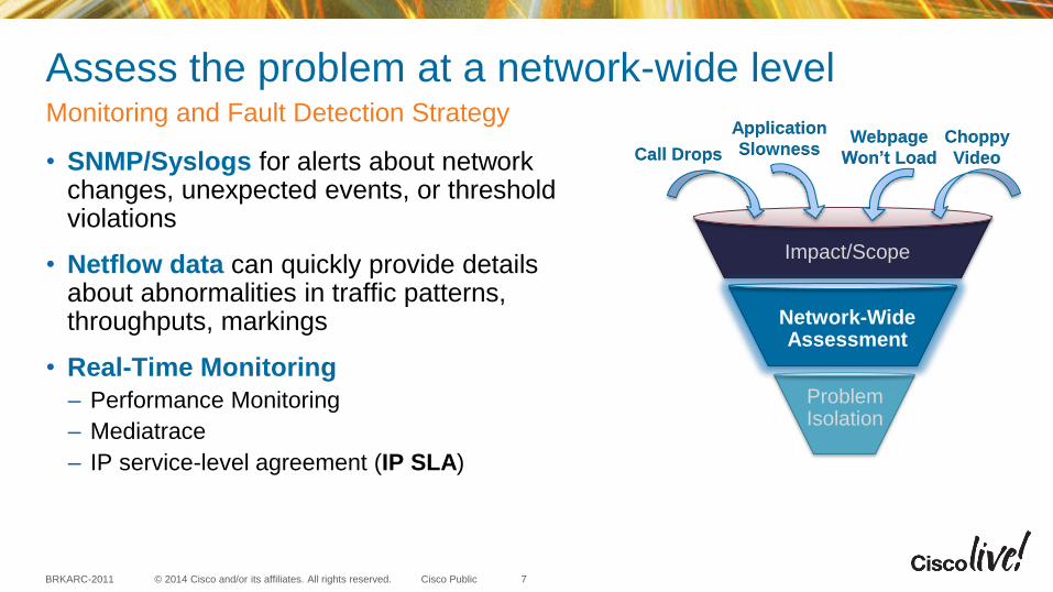
• SNMP/Syslogs for alerts about network changes, unexpected events, or threshold violations
• Netflow data can quickly provide details about abnormalities in traffic patterns, throughputs, markings
• Real-Time Monitoring
– Performance Monitoring
– Mediatrace
– IP service-level agreement (IP SLA)
Monitoring and Fault Detection Strategy
7
Choppy
Video
Application
Slowness Call Drops Webpage
Won’t Load
Impact/Scope
Network-Wide Assessment
Problem Isolation
© 2014 Cisco and/or its affiliates. All rights reserved. BRKARC-2011 Cisco Public
Real-Time Monitoring
• Performance Monitoring provides performance statistics based on analysis of user traffic
– Configurable thresholds and alerts based on performance reported through Netflow and SNMP
• Mediatrace collects critical information on specific media streams on a per-hop basis to pinpoint source of degradation
– can dynamically configure performance monitor policy on discovered devices on path between endpoints
• IP SLA stress/test network with realistic application-specific media streams
8
For more info… BRKARC-2002 Network Diagnosis: Prevent Prepare Repair
BRKNMS 3132 Advanced NetFlow
BRKCDN-1113 Enhanced Management of Video with Media Monitoring
BRKEVT-2807 Enterprise Video Network Performance Analysis with Medianet
BRKARC-2019 Operating an ASR1000
BRKARC-2021 IOS XE Advanced Troubleshooting
© 2014 Cisco and/or its affiliates. All rights reserved. BRKARC-2011 Cisco Public
Isolating the problem further
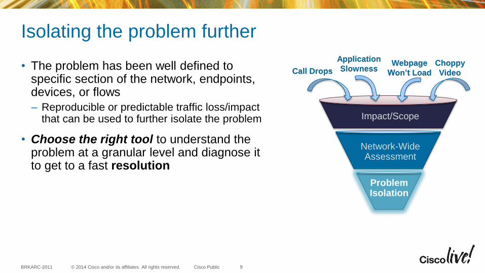
• The problem has been well defined to specific section of the network, endpoints, devices, or flows
– Reproducible or predictable traffic loss/impact that can be used to further isolate the problem
• Choose the right tool to understand the problem at a granular level and diagnose it to get to a fast resolution
9
Choppy
Video
Application
Slowness Call Drops Webpage
Won’t Load
Impact/Scope
Network-Wide Assessment
Problem Isolation
© 2014 Cisco and/or its affiliates. All rights reserved. BRKARC-2011 Cisco Public
Taxonomy of the Troubleshooting Tools
10
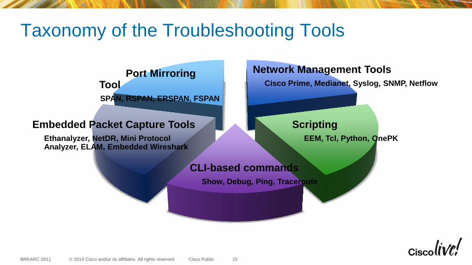
Port Mirroring Tool
SPAN, RSPAN, ERSPAN, FSPAN
CLI-based commands
Show, Debug, Ping, Traceroute
Embedded Packet Capture Tools
Ethanalyzer, NetDR, Mini Protocol Analyzer, ELAM, Embedded Wireshark
Scripting
EEM, Tcl, Python, OnePK
Network Management Tools
Cisco Prime, Medianet, Syslog, SNMP, Netflow
© 2014 Cisco and/or its affiliates. All rights reserved. BRKARC-2011 Cisco Public
Our Focus ….
11
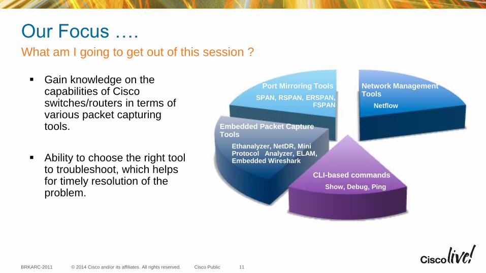
Embedded Packet Capture Tools
Ethanalyzer, NetDR, Mini Protocol Analyzer, ELAM, Embedded Wireshark
Port Mirroring Tools
SPAN, RSPAN, ERSPAN, FSPAN
CLI-based commands
Show, Debug, Ping
Network Management Tools
Netflow
Gain knowledge on the capabilities of Cisco switches/routers in terms of various packet capturing tools.
Ability to choose the right tool to troubleshoot, which helps for timely resolution of the problem.
What am I going to get out of this session ?
© 2014 Cisco and/or its affiliates. All rights reserved. BRKARC-2011 Cisco Public
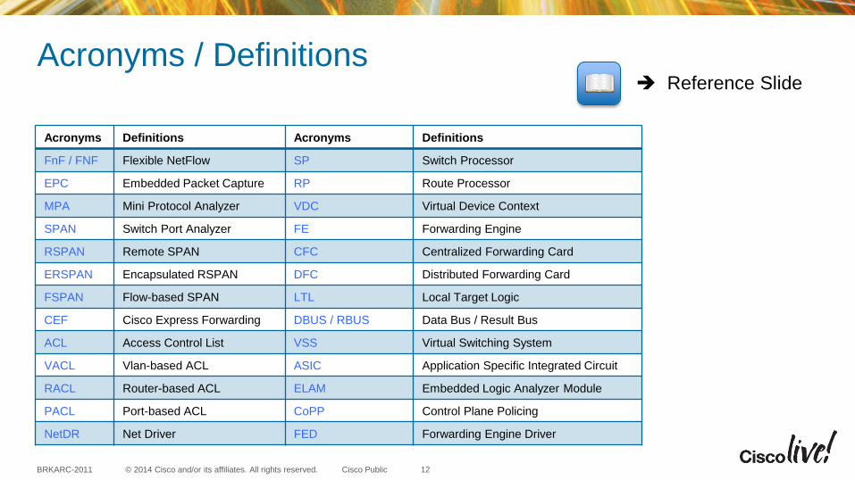
Acronyms / Definitions
Acronyms Definitions Acronyms Definitions
FnF / FNF Flexible NetFlow SP Switch Processor
EPC Embedded Packet Capture RP Route Processor
MPA Mini Protocol Analyzer VDC Virtual Device Context
SPAN Switch Port Analyzer FE Forwarding Engine
RSPAN Remote SPAN CFC Centralized Forwarding Card
ERSPAN Encapsulated RSPAN DFC Distributed Forwarding Card
FSPAN Flow-based SPAN LTL Local Target Logic
CEF Cisco Express Forwarding DBUS / RBUS Data Bus / Result Bus
ACL Access Control List VSS Virtual Switching System
VACL Vlan-based ACL ASIC Application Specific Integrated Circuit
RACL Router-based ACL ELAM Embedded Logic Analyzer Module
PACL Port-based ACL CoPP Control Plane Policing
NetDR Net Driver FED Forwarding Engine Driver
12
Reference Slide
© 2014 Cisco and/or its affiliates. All rights reserved. BRKARC-2011 Cisco Public
Agenda
• Introduction
• Capturing Packets at the Control Plane
• Capturing Packets at the Data Plane
• Tips and Tricks
• Putting it All Together
• Q&A
13
Platform Independent Tools (Flexible NetFlow, Show and Debug commands)
© 2014 Cisco and/or its affiliates. All rights reserved. BRKARC-2011 Cisco Public
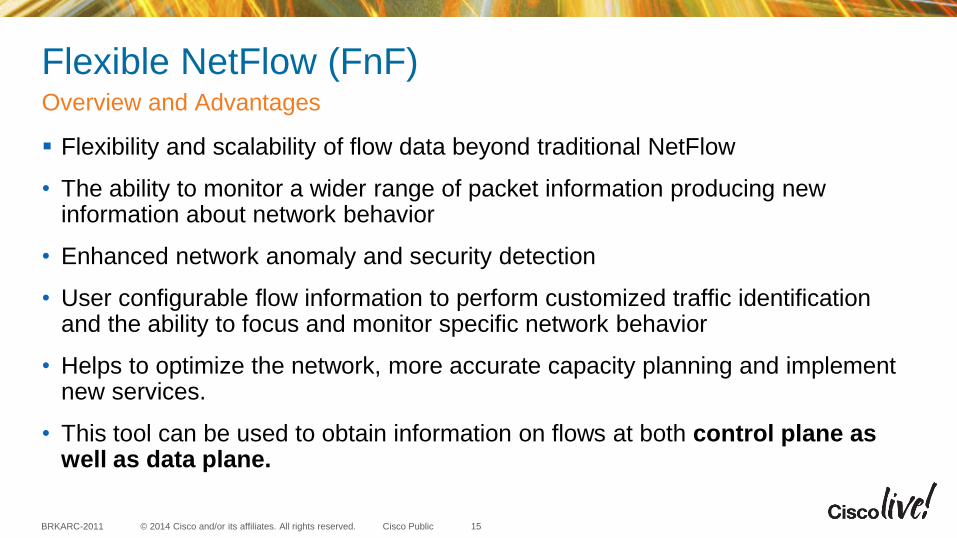
Flexible NetFlow (FnF)
Flexibility and scalability of flow data beyond traditional NetFlow
• The ability to monitor a wider range of packet information producing new information about network behavior
• Enhanced network anomaly and security detection
• User configurable flow information to perform customized traffic identification and the ability to focus and monitor specific network behavior
• Helps to optimize the network, more accurate capacity planning and implement new services.
• This tool can be used to obtain information on flows at both control plane as well as data plane.
Overview and Advantages
15
© 2014 Cisco and/or its affiliates. All rights reserved. BRKARC-2011 Cisco Public
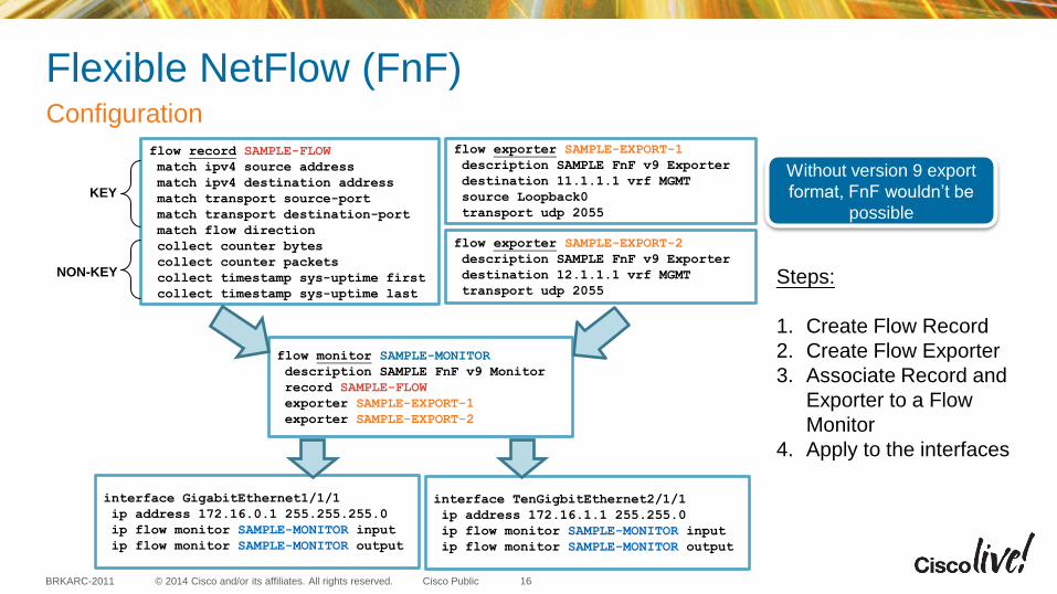
Flexible NetFlow (FnF) Configuration
16
flow record SAMPLE-FLOW
match ipv4 source address
match ipv4 destination address
match transport source-port
match transport destination-port
match flow direction
collect counter bytes
collect counter packets
collect timestamp sys-uptime first
collect timestamp sys-uptime last
flow exporter SAMPLE-EXPORT-1
description SAMPLE FnF v9 Exporter
destination 11.1.1.1 vrf MGMT
source Loopback0
transport udp 2055
flow exporter SAMPLE-EXPORT-2
description SAMPLE FnF v9 Exporter
destination 12.1.1.1 vrf MGMT
transport udp 2055
flow monitor SAMPLE-MONITOR
description SAMPLE FnF v9 Monitor
record SAMPLE-FLOW
exporter SAMPLE-EXPORT-1
exporter SAMPLE-EXPORT-2
interface GigabitEthernet1/1/1
ip address 172.16.0.1 255.255.255.0
ip flow monitor SAMPLE-MONITOR input
ip flow monitor SAMPLE-MONITOR output
interface TenGigbitEthernet2/1/1
ip address 172.16.1.1 255.255.0
ip flow monitor SAMPLE-MONITOR input
ip flow monitor SAMPLE-MONITOR output
NON-KEY
KEY
Steps:
1. Create Flow Record
2. Create Flow Exporter
3. Associate Record and
Exporter to a Flow
Monitor
4. Apply to the interfaces
Without version 9 export
format, FnF wouldn’t be
possible
© 2014 Cisco and/or its affiliates. All rights reserved. BRKARC-2011 Cisco Public
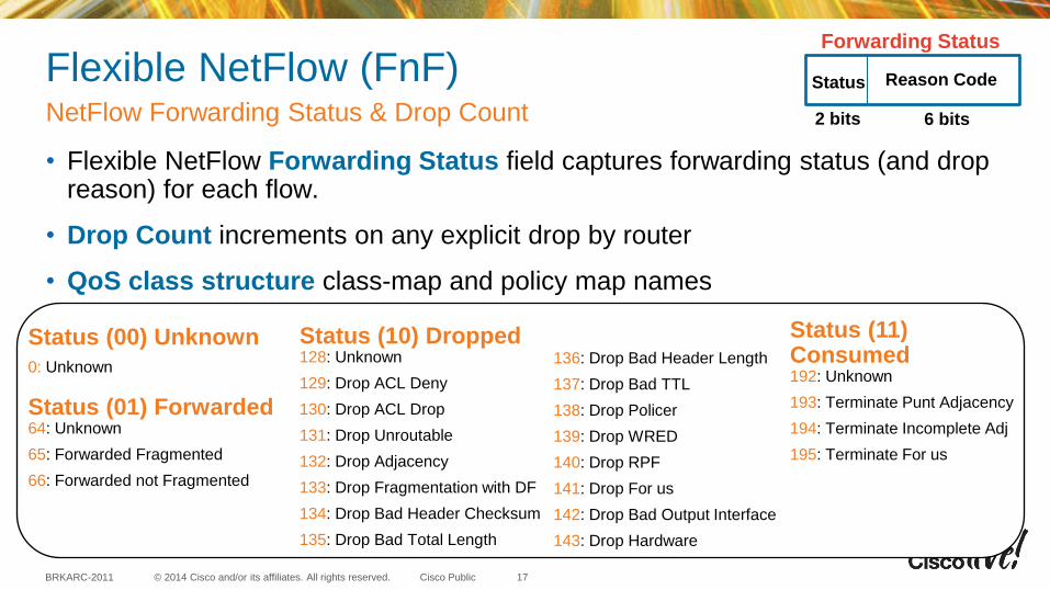
Flexible NetFlow (FnF)
• Flexible NetFlow Forwarding Status field captures forwarding status (and drop reason) for each flow.
• Drop Count increments on any explicit drop by router
• QoS class structure class-map and policy map names
NetFlow Forwarding Status & Drop Count
17
Reason Code Status
6 bits 2 bits
Forwarding Status
Status (00) Unknown
0: Unknown
Status (01) Forwarded 64: Unknown
65: Forwarded Fragmented
66: Forwarded not Fragmented
Status (10) Dropped 128: Unknown
129: Drop ACL Deny
130: Drop ACL Drop
131: Drop Unroutable
132: Drop Adjacency
133: Drop Fragmentation with DF
134: Drop Bad Header Checksum
135: Drop Bad Total Length
136: Drop Bad Header Length
137: Drop Bad TTL
138: Drop Policer
139: Drop WRED
140: Drop RPF
141: Drop For us
142: Drop Bad Output Interface
143: Drop Hardware
Status (11) Consumed 192: Unknown
193: Terminate Punt Adjacency
194: Terminate Incomplete Adj
195: Terminate For us
© 2014 Cisco and/or its affiliates. All rights reserved. BRKARC-2011 Cisco Public
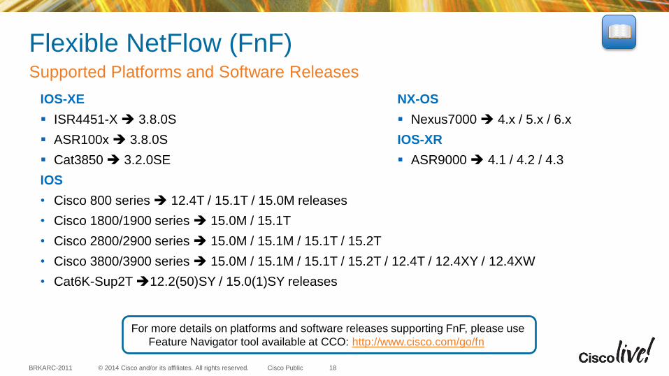
Flexible NetFlow (FnF) Supported Platforms and Software Releases
18
IOS-XE
ISR4451-X 3.8.0S
ASR100x 3.8.0S
Cat3850 3.2.0SE
IOS
• Cisco 800 series 12.4T / 15.1T / 15.0M releases
• Cisco 1800/1900 series 15.0M / 15.1T
• Cisco 2800/2900 series 15.0M / 15.1M / 15.1T / 15.2T
• Cisco 3800/3900 series 15.0M / 15.1M / 15.1T / 15.2T / 12.4T / 12.4XY / 12.4XW
• Cat6K-Sup2T 12.2(50)SY / 15.0(1)SY releases
For more details on platforms and software releases supporting FnF, please use
Feature Navigator tool available at CCO: http://www.cisco.com/go/fn
NX-OS
Nexus7000 4.x / 5.x / 6.x
IOS-XR
ASR9000 4.1 / 4.2 / 4.3
© 2014 Cisco and/or its affiliates. All rights reserved. BRKARC-2011 Cisco Public
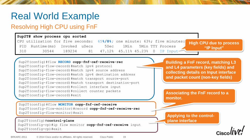
Sup2T(config)#control-plane
Sup2T(config-cp)#ip flow monitor copp-fnf-cef-receive input
Sup2T(config-cp)#exit
Sup2T(config)#flow MONITOR copp-fnf-cef-receive
Sup2T(config-flow-monitor)#record copp-fnf-cef-receive-rec
Sup2T(config-flow-monitor)#exit
Sup2T(config)#flow RECORD copp-fnf-cef-receive-rec
Sup2T(config-flow-record)#match ipv4 protocol
Sup2T(config-flow-record)#match ipv4 source address
Sup2T(config-flow-record)#match ipv4 destination address
Sup2T(config-flow-record)#match transport source-port
Sup2T(config-flow-record)#match transport destination-port
Sup2T(config-flow-record)#collect interface input
Sup2T(config-flow-record)#collect counter packets
Sup2T(config-flow-record)#exit
Real World Example Resolving High CPU using FnF
19
Sup2T# show process cpu sorted
CPU utilization for five seconds: 65%/8%; one minute: 63%; five minutes: 61%
PID Runtime(ms) Invoked uSecs 5Sec 1Min 5Min TTY Process
310 30544 189234 81 47.12% 45.11% 45.23% 0 IP Input
High CPU due to process
“IP Input”
Building a FnF record, matching L3
and L4 parameters (key fields) and
collecting details on Input interface
and packet count (non-key fields)
Associating the FnF record to a
monitor.
Applying to the control-
plane interface
© 2014 Cisco and/or its affiliates. All rights reserved. BRKARC-2011 Cisco Public
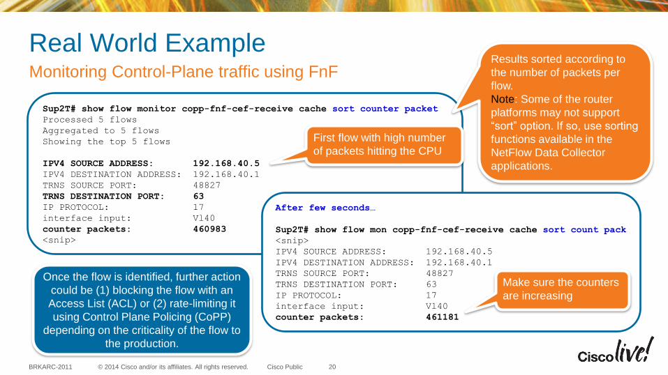
Real World Example Monitoring Control-Plane traffic using FnF
20
Sup2T# show flow monitor copp-fnf-cef-receive cache sort counter packet
Processed 5 flows
Aggregated to 5 flows
Showing the top 5 flows
IPV4 SOURCE ADDRESS: 192.168.40.5
IPV4 DESTINATION ADDRESS: 192.168.40.1
TRNS SOURCE PORT: 48827
TRNS DESTINATION PORT: 63
IP PROTOCOL: 17
interface input: Vl40
counter packets: 460983
<snip>
After few seconds…
Sup2T# show flow mon copp-fnf-cef-receive cache sort count pack
<snip>
IPV4 SOURCE ADDRESS: 192.168.40.5
IPV4 DESTINATION ADDRESS: 192.168.40.1
TRNS SOURCE PORT: 48827
TRNS DESTINATION PORT: 63
IP PROTOCOL: 17
interface input: Vl40
counter packets: 461181
First flow with high number
of packets hitting the CPU
Make sure the counters
are increasing
Once the flow is identified, further action
could be (1) blocking the flow with an
Access List (ACL) or (2) rate-limiting it
using Control Plane Policing (CoPP)
depending on the criticality of the flow to
the production.
Results sorted according to
the number of packets per
flow.
Note: Some of the router
platforms may not support
“sort” option. If so, use sorting
functions available in the
NetFlow Data Collector
applications.
© 2014 Cisco and/or its affiliates. All rights reserved. BRKARC-2011 Cisco Public
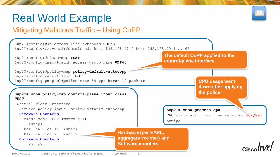
Real World Example Mitigating Malicious Traffic – Using CoPP
21
Sup2T(config)#ip access-list extended UDP63
Sup2T(config-ext-nacl)#permit udp host 192.168.40.5 host 192.168.40.1 eq 63
Sup2T(config)#class-map TEST
Sup2T(config-cmap)#match access-group name UDP63
Sup2T(config)#policy-map policy-default-autocopp
Sup2T(config-pmap)#class TEST
Sup2T(config-pmap-c)#police rate 50 pps burst 10 packets
The default CoPP applied to the
control-plane interface
Sup2T# show process cpu
CPU utilization for five seconds: 10%/8%;
<snip>
Sup2T# show policy-map control-plane input class
TEST
Control Plane Interface
Service-policy input: policy-default-autocopp
Hardware Counters:
class-map: TEST (match-all)
<snip>
Earl in Slot 1: <snip>
Earl in Slot 2: <snip>
Software Counters:
<snip>
Hardware (per EARL,
aggregate counter) and
Software counters
CPU usage went
down after applying
the policer
© 2014 Cisco and/or its affiliates. All rights reserved. BRKARC-2011 Cisco Public
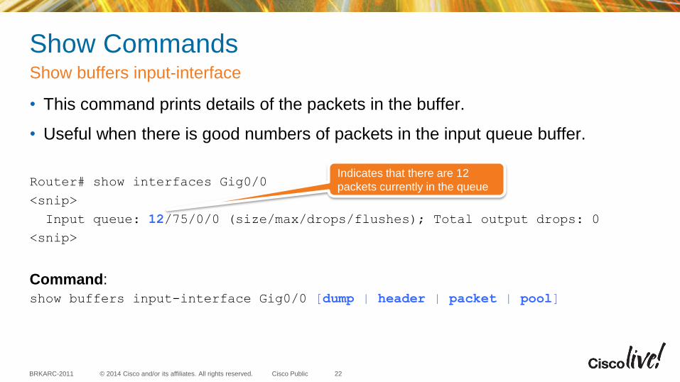
Show Commands
• This command prints details of the packets in the buffer.
• Useful when there is good numbers of packets in the input queue buffer.
Router# show interfaces Gig0/0
<snip>
Input queue: 12/75/0/0 (size/max/drops/flushes); Total output drops: 0
<snip>
Command:
show buffers input-interface Gig0/0 [dump | header | packet | pool]
Show buffers input-interface
22
Indicates that there are 12
packets currently in the queue
© 2014 Cisco and/or its affiliates. All rights reserved. BRKARC-2011 Cisco Public
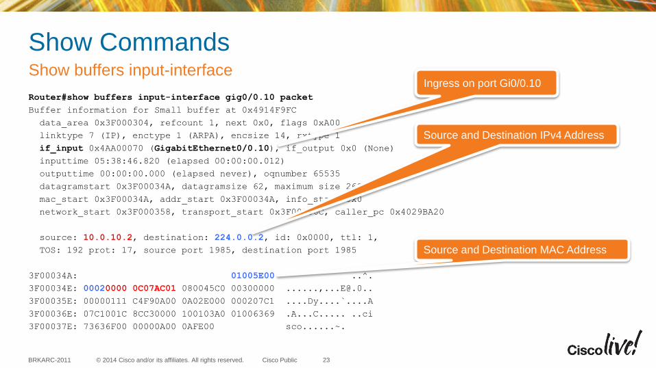
Show Commands
Router#show buffers input-interface gig0/0.10 packet
Buffer information for Small buffer at 0x4914F9FC
data_area 0x3F000304, refcount 1, next 0x0, flags 0xA00
linktype 7 (IP), enctype 1 (ARPA), encsize 14, rxtype 1
if_input 0x4AA00070 (GigabitEthernet0/0.10), if_output 0x0 (None)
inputtime 05:38:46.820 (elapsed 00:00:00.012)
outputtime 00:00:00.000 (elapsed never), oqnumber 65535
datagramstart 0x3F00034A, datagramsize 62, maximum size 260
mac_start 0x3F00034A, addr_start 0x3F00034A, info_start 0x0
network_start 0x3F000358, transport_start 0x3F00036C, caller_pc 0x4029BA20
source: 10.0.10.2, destination: 224.0.0.2, id: 0x0000, ttl: 1,
TOS: 192 prot: 17, source port 1985, destination port 1985
3F00034A: 01005E00 ..^.
3F00034E: 00020000 0C07AC01 080045C0 00300000 ......,[email protected]..
3F00035E: 00000111 C4F90A00 0A02E000 000207C1 ....Dy....`....A
3F00036E: 07C1001C 8CC30000 100103A0 01006369 .A...C..... ..ci
3F00037E: 73636F00 00000A00 0AFE00 sco......~.
Show buffers input-interface
23
Ingress on port Gi0/0.10
Source and Destination IPv4 Address
Source and Destination MAC Address
© 2014 Cisco and/or its affiliates. All rights reserved. BRKARC-2011 Cisco Public
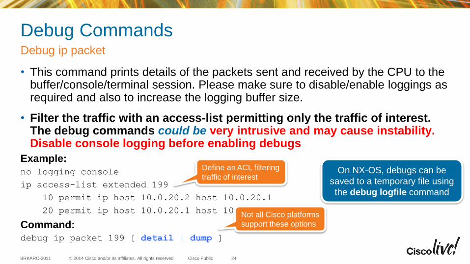
Debug Commands
• This command prints details of the packets sent and received by the CPU to the buffer/console/terminal session. Please make sure to disable/enable loggings as required and also to increase the logging buffer size.
• Filter the traffic with an access-list permitting only the traffic of interest. The debug commands could be very intrusive and may cause instability. Disable console logging before enabling debugs
Example:
no logging console
ip access-list extended 199
10 permit ip host 10.0.20.2 host 10.0.20.1
20 permit ip host 10.0.20.1 host 10.0.20.2
Command:
debug ip packet 199 [ detail | dump ]
Debug ip packet
24
Define an ACL filtering
traffic of interest
Not all Cisco platforms
support these options
On NX-OS, debugs can be
saved to a temporary file using
the debug logfile command
© 2014 Cisco and/or its affiliates. All rights reserved. BRKARC-2011 Cisco Public
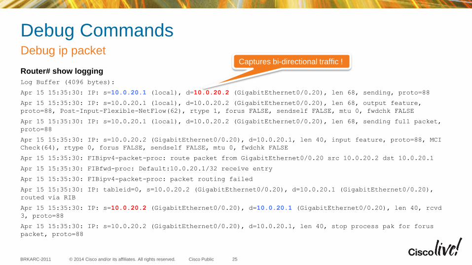
Debug Commands
Router# show logging
Log Buffer (4096 bytes):
Apr 15 15:35:30: IP: s=10.0.20.1 (local), d=10.0.20.2 (GigabitEthernet0/0.20), len 68, sending, proto=88
Apr 15 15:35:30: IP: s=10.0.20.1 (local), d=10.0.20.2 (GigabitEthernet0/0.20), len 68, output feature,
proto=88, Post-Input-Flexible-NetFlow(62), rtype 1, forus FALSE, sendself FALSE, mtu 0, fwdchk FALSE
Apr 15 15:35:30: IP: s=10.0.20.1 (local), d=10.0.20.2 (GigabitEthernet0/0.20), len 68, sending full packet,
proto=88
Apr 15 15:35:30: IP: s=10.0.20.2 (GigabitEthernet0/0.20), d=10.0.20.1, len 40, input feature, proto=88, MCI
Check(64), rtype 0, forus FALSE, sendself FALSE, mtu 0, fwdchk FALSE
Apr 15 15:35:30: FIBipv4-packet-proc: route packet from GigabitEthernet0/0.20 src 10.0.20.2 dst 10.0.20.1
Apr 15 15:35:30: FIBfwd-proc: Default:10.0.20.1/32 receive entry
Apr 15 15:35:30: FIBipv4-packet-proc: packet routing failed
Apr 15 15:35:30: IP: tableid=0, s=10.0.20.2 (GigabitEthernet0/0.20), d=10.0.20.1 (GigabitEthernet0/0.20),
routed via RIB
Apr 15 15:35:30: IP: s=10.0.20.2 (GigabitEthernet0/0.20), d=10.0.20.1 (GigabitEthernet0/0.20), len 40, rcvd
3, proto=88
Apr 15 15:35:30: IP: s=10.0.20.2 (GigabitEthernet0/0.20), d=10.0.20.1, len 40, stop process pak for forus
packet, proto=88
Debug ip packet
25
Captures bi-directional traffic !
Platform Dependent Tools (CPU Queue Debug, FED Tracing, Ethanalyzer and NetDR)
© 2014 Cisco and/or its affiliates. All rights reserved. BRKARC-2011 Cisco Public
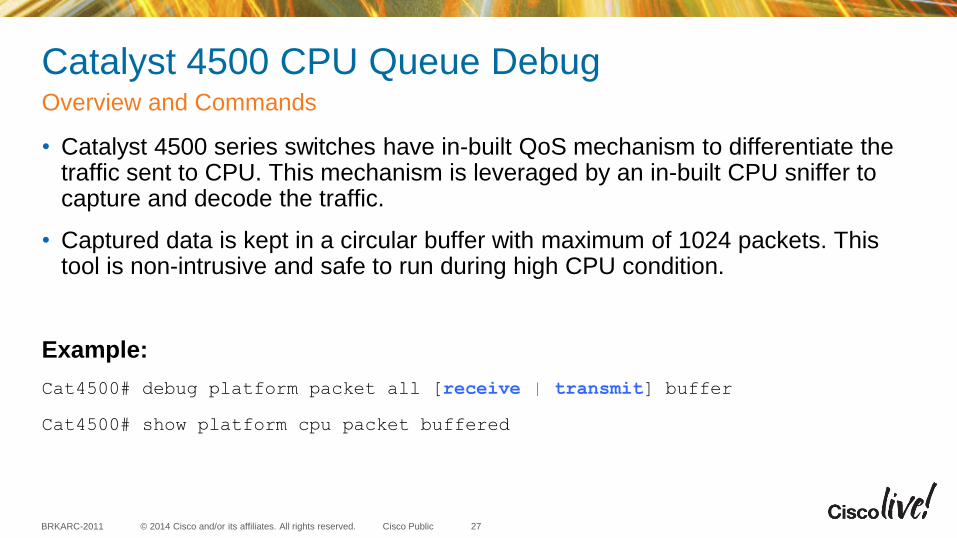
Catalyst 4500 CPU Queue Debug
• Catalyst 4500 series switches have in-built QoS mechanism to differentiate the traffic sent to CPU. This mechanism is leveraged by an in-built CPU sniffer to capture and decode the traffic.
• Captured data is kept in a circular buffer with maximum of 1024 packets. This tool is non-intrusive and safe to run during high CPU condition.
Example:
Cat4500# debug platform packet all [receive | transmit] buffer
Cat4500# show platform cpu packet buffered
Overview and Commands
27
© 2014 Cisco and/or its affiliates. All rights reserved. BRKARC-2011 Cisco Public
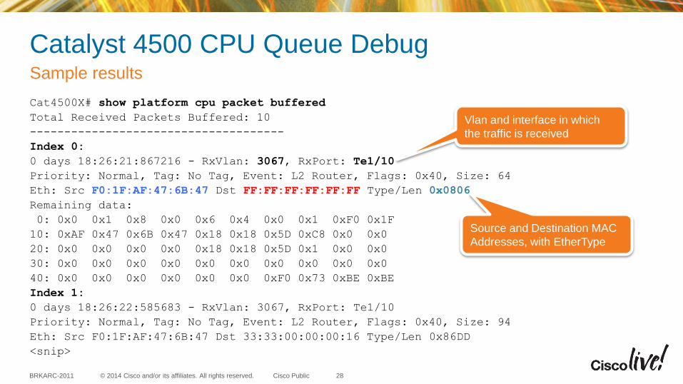
Catalyst 4500 CPU Queue Debug
Cat4500X# show platform cpu packet buffered
Total Received Packets Buffered: 10
-------------------------------------
Index 0:
0 days 18:26:21:867216 - RxVlan: 3067, RxPort: Te1/10
Priority: Normal, Tag: No Tag, Event: L2 Router, Flags: 0x40, Size: 64
Eth: Src F0:1F:AF:47:6B:47 Dst FF:FF:FF:FF:FF:FF Type/Len 0x0806
Remaining data:
0: 0x0 0x1 0x8 0x0 0x6 0x4 0x0 0x1 0xF0 0x1F
10: 0xAF 0x47 0x6B 0x47 0x18 0x18 0x5D 0xC8 0x0 0x0
20: 0x0 0x0 0x0 0x0 0x18 0x18 0x5D 0x1 0x0 0x0
30: 0x0 0x0 0x0 0x0 0x0 0x0 0x0 0x0 0x0 0x0
40: 0x0 0x0 0x0 0x0 0x0 0x0 0xF0 0x73 0xBE 0xBE
Index 1:
0 days 18:26:22:585683 - RxVlan: 3067, RxPort: Te1/10
Priority: Normal, Tag: No Tag, Event: L2 Router, Flags: 0x40, Size: 94
Eth: Src F0:1F:AF:47:6B:47 Dst 33:33:00:00:00:16 Type/Len 0x86DD
<snip>
Sample results
28
Source and Destination MAC
Addresses, with EtherType
Vlan and interface in which
the traffic is received

© 2014 Cisco and/or its affiliates. All rights reserved. BRKARC-2011 Cisco Public
Catalyst 3850 FED Tracing
• Forwarding Engine Driver (FED) is the heart of Cisco Unified Access switching platforms (like Catalyst 3850), and responsible for hardware programming and forwarding.
• FED tracing is a mechanism to capture packets sent by FED towards the CPU.
Example:
Cat3850# set trace control fed-punject-detail [ enable | disable | clear ]
Cat3850# set trace fed-punject-detail direction [ rx | tx ] <filters>
Cat3850# set trace control fed-punject-detail buffer-size <bytes>
Overview and Commands
29
© 2014 Cisco and/or its affiliates. All rights reserved. BRKARC-2011 Cisco Public
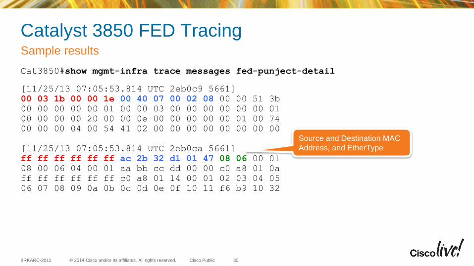
Catalyst 3850 FED Tracing
Cat3850#show mgmt-infra trace messages fed-punject-detail
[11/25/13 07:05:53.814 UTC 2eb0c9 5661]
00 03 1b 00 00 1e 00 40 07 00 02 08 00 00 51 3b
00 00 00 00 00 01 00 00 03 00 00 00 00 00 00 01
00 00 00 00 20 00 00 0e 00 00 00 00 00 01 00 74
00 00 00 04 00 54 41 02 00 00 00 00 00 00 00 00
[11/25/13 07:05:53.814 UTC 2eb0ca 5661]
ff ff ff ff ff ff ac 2b 32 d1 01 47 08 06 00 01
08 00 06 04 00 01 aa bb cc dd 00 00 c0 a8 01 0a
ff ff ff ff ff ff c0 a8 01 14 00 01 02 03 04 05
06 07 08 09 0a 0b 0c 0d 0e 0f 10 11 f6 b9 10 32
Sample results
30
Source and Destination MAC
Address, and EtherType
© 2014 Cisco and/or its affiliates. All rights reserved. BRKARC-2011 Cisco Public
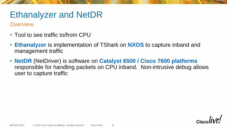
Ethanalyzer and NetDR
• Tool to see traffic to/from CPU
• Ethanalyzer is implementation of TShark on NXOS to capture inband and management traffic
• NetDR (NetDriver) is software on Catalyst 6500 / Cisco 7600 platforms responsible for handling packets on CPU inband. Non-intrusive debug allows user to capture traffic
Overview
31
© 2014 Cisco and/or its affiliates. All rights reserved. BRKARC-2011 Cisco Public
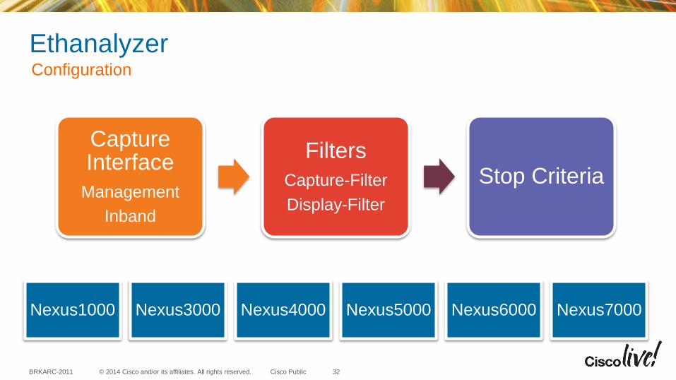
Ethanalyzer Configuration
32
Nexus1000 Nexus3000 Nexus4000 Nexus5000 Nexus6000 Nexus7000
Capture Interface
Management
Inband
Filters
Capture-Filter
Display-Filter
Stop Criteria
© 2014 Cisco and/or its affiliates. All rights reserved. BRKARC-2011 Cisco Public
Ethanalyzer
Nexus devices have multiple capture interfaces depending on platform
1. Mgmt – Captures traffic on the mgmt0 interface of the switch
2. Inbound-Hi – Captures high-priority control packets on the inband such as STP, LACP, CDP, Data Center Bridging Exchange (DCBX), Fiber Channel, and FCOE
3. Inbound-Lo – Captures low-priority control packets on the inband such as IGMP, TCP, UDP, IP, and ARP traffic.
Note, Nexus7000 and Nexus4000 each have only a single inband interface that captures all inband traffic.
Configuration - Capture Interface
33
© 2014 Cisco and/or its affiliates. All rights reserved. BRKARC-2011 Cisco Public
Ethanalyzer
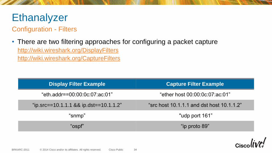
• There are two filtering approaches for configuring a packet capture
http://wiki.wireshark.org/DisplayFilters
http://wiki.wireshark.org/CaptureFilters
Configuration - Filters
34
Display Filter Example Capture Filter Example
“eth.addr==00:00:0c:07:ac:01” “ether host 00:00:0c:07:ac:01”
“ip.src==10.1.1.1 && ip.dst==10.1.1.2” “src host 10.1.1.1 and dst host 10.1.1.2”
“snmp” "udp port 161”
“ospf” “ip proto 89”
© 2014 Cisco and/or its affiliates. All rights reserved. BRKARC-2011 Cisco Public
Ethanalyzer
• Which filter is best to use?
• More robust filtering available via display-filter and any proprietary shim headers do not interfere with filter. This is generally the best filter to use.
• On Nexus7000, frames not matching display-filter are still captured but not displayed. Ethanalyzer may end before matching any frames in display-filter, as the capture stops once limit-capture-frames threshold is met.
• On Nexus7000, use capture-filter and only frames matching the filter are captured. Alternatively, use display-filter with high limit-capture-frames threshold.
Configuration - Filters
35
© 2014 Cisco and/or its affiliates. All rights reserved. BRKARC-2011 Cisco Public
Ethanalyzer
• By default, Ethanalyzer stops after capturing 10 frames. This can be changed by updating limit-captured-frames (0 means no limit).
• This can be used in conjunction with a capture-ring-buffer to create multiple files. New files can be created based on duration or filesize. The total number of files written can be control with the files parameter.
• autostop can be used to stop the capture after a certain duration, filesize, or total number of files.
Configuration - Stop Criteria
36
© 2014 Cisco and/or its affiliates. All rights reserved. BRKARC-2011 Cisco Public
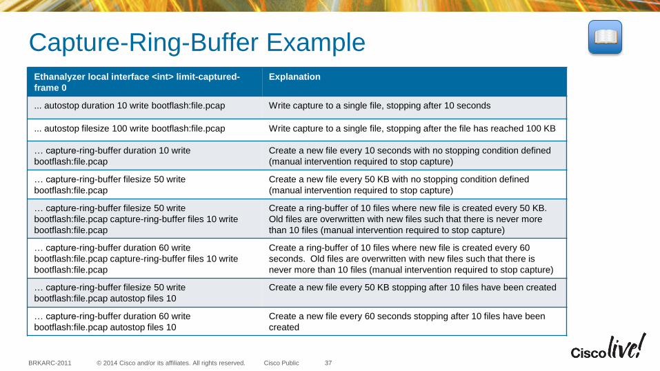
Capture-Ring-Buffer Example
37
Ethanalyzer local interface <int> limit-captured-
frame 0
Explanation
... autostop duration 10 write bootflash:file.pcap Write capture to a single file, stopping after 10 seconds
... autostop filesize 100 write bootflash:file.pcap Write capture to a single file, stopping after the file has reached 100 KB
… capture-ring-buffer duration 10 write
bootflash:file.pcap
Create a new file every 10 seconds with no stopping condition defined
(manual intervention required to stop capture)
… capture-ring-buffer filesize 50 write
bootflash:file.pcap
Create a new file every 50 KB with no stopping condition defined
(manual intervention required to stop capture)
… capture-ring-buffer filesize 50 write
bootflash:file.pcap capture-ring-buffer files 10 write
bootflash:file.pcap
Create a ring-buffer of 10 files where new file is created every 50 KB.
Old files are overwritten with new files such that there is never more
than 10 files (manual intervention required to stop capture)
… capture-ring-buffer duration 60 write
bootflash:file.pcap capture-ring-buffer files 10 write
bootflash:file.pcap
Create a ring-buffer of 10 files where new file is created every 60
seconds. Old files are overwritten with new files such that there is
never more than 10 files (manual intervention required to stop capture)
… capture-ring-buffer filesize 50 write
bootflash:file.pcap autostop files 10
Create a new file every 50 KB stopping after 10 files have been created
… capture-ring-buffer duration 60 write
bootflash:file.pcap autostop files 10
Create a new file every 60 seconds stopping after 10 files have been
created

© 2014 Cisco and/or its affiliates. All rights reserved. BRKARC-2011 Cisco Public
Ethanalyzer
• Captures on inbound-hi interface
• Uses a display-filter searching for “stp” frames
• Sets limit-captured-frames to zero to allow continuous capturing of frames
• Uses a capture-ring-buffer to create a new file every 200 KB
• autostop after 5 files have been created
Putting it all together
38
NxOS# ethanalyzer local interface inbound-hi display-filter "stp" limit-captured-
frames 0 capture-ring-buffer filesize 200 write bootflash:stp_ring.pcap autostop
files 5
© 2014 Cisco and/or its affiliates. All rights reserved. BRKARC-2011 Cisco Public
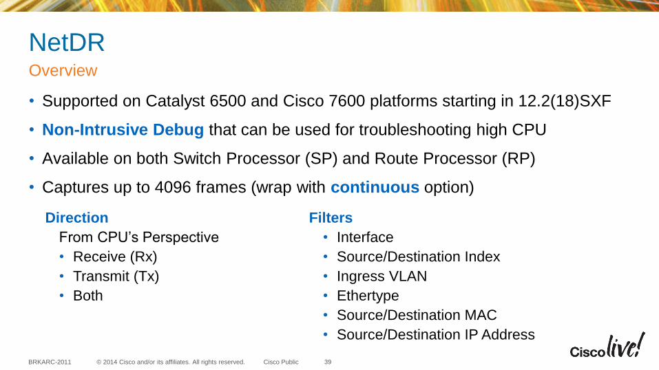
NetDR
• Supported on Catalyst 6500 and Cisco 7600 platforms starting in 12.2(18)SXF
• Non-Intrusive Debug that can be used for troubleshooting high CPU
• Available on both Switch Processor (SP) and Route Processor (RP)
• Captures up to 4096 frames (wrap with continuous option)
Overview
39
Direction
From CPU’s Perspective
• Receive (Rx)
• Transmit (Tx)
• Both
Filters
• Interface
• Source/Destination Index
• Ingress VLAN
• Ethertype
• Source/Destination MAC
• Source/Destination IP Address
© 2014 Cisco and/or its affiliates. All rights reserved. BRKARC-2011 Cisco Public
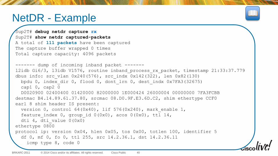
NetDR - Example
40
Sup2T# debug netdr capture rx
Sup2T# show netdr captured-packets
A total of 111 packets have been captured
The capture buffer wrapped 0 times
Total capture capacity: 4096 packets
------- dump of incoming inband packet -------
l2idb Gi6/3, l3idb Vl576, routine inband_process_rx_packet, timestamp 21:33:37.779
dbus info: src_vlan 0x240(576), src_indx 0x142(322), len 0x82(130)
bpdu 0, index_dir 0, flood 0, dont_lrn 0, dest_indx 0x7FA3(32675)
cap1 0, cap2 0
D0020900 02400400 01420000 82000000 1E000424 26000004 00000000 7FA3FCBB
destmac B4.14.89.61.37.80, srcmac 08.D0.9F.E3.6D.C2, shim ethertype CCF0
earl 8 shim header IS present:
version 0, control 64(0x40), lif 576(0x240), mark_enable 1,
feature_index 0, group_id 0(0x0), acos 0(0x0), ttl 14,
dti 4, dti_value 0(0x0)
ethertype 0800
protocol ip: version 0x04, hlen 0x05, tos 0x00, totlen 100, identifier 5
df 0, mf 0, fo 0, ttl 255, src 14.2.36.1, dst 14.2.36.11
icmp type 8, code 0
© 2014 Cisco and/or its affiliates. All rights reserved. BRKARC-2011 Cisco Public
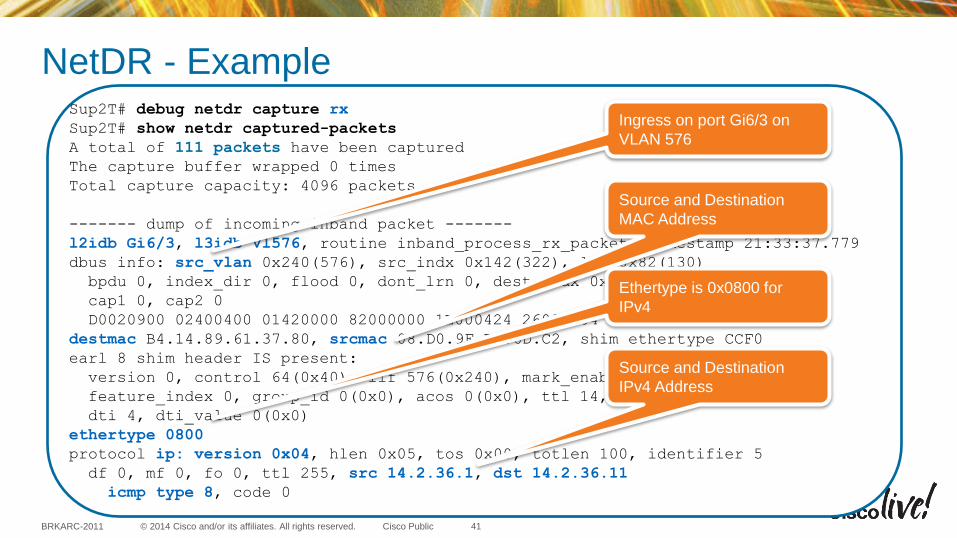
NetDR - Example
41
Sup2T# debug netdr capture rx
Sup2T# show netdr captured-packets
A total of 111 packets have been captured
The capture buffer wrapped 0 times
Total capture capacity: 4096 packets
------- dump of incoming inband packet -------
l2idb Gi6/3, l3idb Vl576, routine inband_process_rx_packet, timestamp 21:33:37.779
dbus info: src_vlan 0x240(576), src_indx 0x142(322), len 0x82(130)
bpdu 0, index_dir 0, flood 0, dont_lrn 0, dest_indx 0x7FA3(32675)
cap1 0, cap2 0
D0020900 02400400 01420000 82000000 1E000424 26000004 00000000 7FA3FCBB
destmac B4.14.89.61.37.80, srcmac 08.D0.9F.E3.6D.C2, shim ethertype CCF0
earl 8 shim header IS present:
version 0, control 64(0x40), lif 576(0x240), mark_enable 1,
feature_index 0, group_id 0(0x0), acos 0(0x0), ttl 14,
dti 4, dti_value 0(0x0)
ethertype 0800
protocol ip: version 0x04, hlen 0x05, tos 0x00, totlen 100, identifier 5
df 0, mf 0, fo 0, ttl 255, src 14.2.36.1, dst 14.2.36.11
icmp type 8, code 0
Ingress on port Gi6/3 on
VLAN 576
Source and Destination
MAC Address
Ethertype is 0x0800 for
IPv4
Source and Destination
IPv4 Address
© 2014 Cisco and/or its affiliates. All rights reserved. BRKARC-2011 Cisco Public
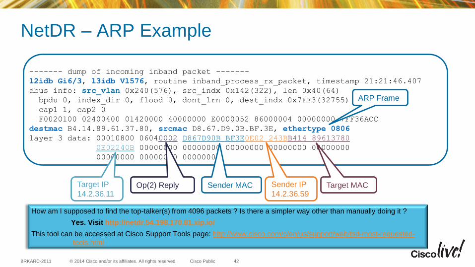
NetDR – ARP Example
42
------- dump of incoming inband packet -------
l2idb Gi6/3, l3idb Vl576, routine inband_process_rx_packet, timestamp 21:21:46.407
dbus info: src_vlan 0x240(576), src_indx 0x142(322), len 0x40(64)
bpdu 0, index_dir 0, flood 0, dont_lrn 0, dest_indx 0x7FF3(32755)
cap1 1, cap2 0
F0020100 02400400 01420000 40000000 E0000052 86000004 00000000 7FF36ACC
destmac B4.14.89.61.37.80, srcmac D8.67.D9.0B.BF.3E, ethertype 0806
layer 3 data: 00010800 06040002 D867D90B BF3E0E02 243BB414 89613780
0E02240B 00000000 00000000 00000000 00000000 00000000
00000000 00000000 00000000
Sender MAC Op(2) Reply Sender IP
14.2.36.59 Target MAC Target IP
14.2.36.11
ARP Frame
How am I supposed to find the top-talker(s) from 4096 packets ? Is there a simpler way other than manually doing it ?
Yes. Visit http://netdr.54.198.170.81.xip.io/
This tool can be accessed at Cisco Support Tools page: http://www.cisco.com/c/en/us/support/web/tsd-most-requested-
tools.html
© 2014 Cisco and/or its affiliates. All rights reserved. BRKARC-2011 Cisco Public
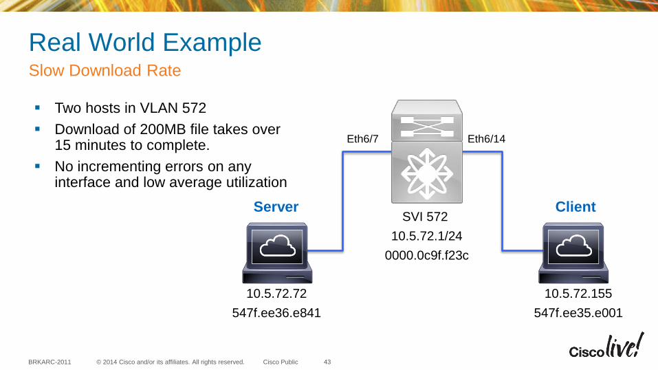
Real World Example Slow Download Rate
43
Two hosts in VLAN 572
Download of 200MB file takes over 15 minutes to complete.
No incrementing errors on any interface and low average utilization
10.5.72.155
547f.ee35.e001
10.5.72.72
547f.ee36.e841
Server Client
Eth6/14 Eth6/7
SVI 572
10.5.72.1/24
0000.0c9f.f23c

© 2014 Cisco and/or its affiliates. All rights reserved. BRKARC-2011 Cisco Public
Real World Example
44
10.5.72.155
547f.ee35.e001
10.5.72.72
547f.ee36.e841
Server Client
Eth6/14 Eth6/7
n7k-dc-dist1# show mac add vlan 572
Legend:
* - primary entry, G - Gateway MAC, (R) - Routed MAC, O - Overlay MAC
age - seconds since last seen,+ - primary entry using vPC Peer-Link
VLAN MAC Address Type age Secure NTFY Ports/SWID.SSID.LID
---------+-----------------+--------+---------+------+----+------------------
G 572 0000.0c9f.f23c static - F F sup-eth1(R)
G 572 64a0.e745.cb41 static - F F sup-eth1(R)
* 572 547f.ee35.e001 dynamic 0 F F Eth6/14
* 572 547f.ee36.e841 dynamic 0 F F Eth6/7
n7k-dc-dist1# show interface e6/7 , e6/14 | i Ethernet6|duplex|rate
Ethernet6/7 is up
full-duplex, 10 Gb/s, media type is 10G
30 seconds input rate 1894904 bits/sec, 490 packets/sec
30 seconds output rate 3015136 bits/sec, 5444 packets/sec
input rate 1.88 Mbps, 402 pps; output rate 3.01 Mbps, 5.38 Kpps
Ethernet6/14 is up
full-duplex, 10 Gb/s, media type is 10G
30 seconds input rate 118224 bits/sec, 189 packets/sec
30 seconds output rate 4500688 bits/sec, 5365 packets/sec
input rate 119.01 Kbps, 66 pps; output rate 4.47 Mbps, 5.31 Kpps
© 2014 Cisco and/or its affiliates. All rights reserved. BRKARC-2011 Cisco Public
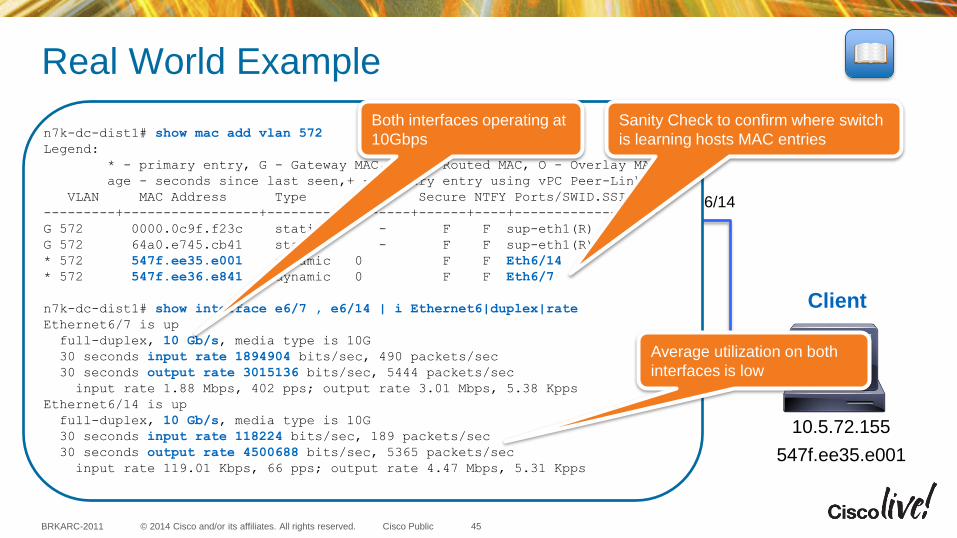
Real World Example
45
10.5.72.155
547f.ee35.e001
10.5.72.72
547f.ee36.e841
Server Client
Eth6/14 Eth6/7
n7k-dc-dist1# show mac add vlan 572
Legend:
* - primary entry, G - Gateway MAC, (R) - Routed MAC, O - Overlay MAC
age - seconds since last seen,+ - primary entry using vPC Peer-Link
VLAN MAC Address Type age Secure NTFY Ports/SWID.SSID.LID
---------+-----------------+--------+---------+------+----+------------------
G 572 0000.0c9f.f23c static - F F sup-eth1(R)
G 572 64a0.e745.cb41 static - F F sup-eth1(R)
* 572 547f.ee35.e001 dynamic 0 F F Eth6/14
* 572 547f.ee36.e841 dynamic 0 F F Eth6/7
n7k-dc-dist1# show interface e6/7 , e6/14 | i Ethernet6|duplex|rate
Ethernet6/7 is up
full-duplex, 10 Gb/s, media type is 10G
30 seconds input rate 1894904 bits/sec, 490 packets/sec
30 seconds output rate 3015136 bits/sec, 5444 packets/sec
input rate 1.88 Mbps, 402 pps; output rate 3.01 Mbps, 5.38 Kpps
Ethernet6/14 is up
full-duplex, 10 Gb/s, media type is 10G
30 seconds input rate 118224 bits/sec, 189 packets/sec
30 seconds output rate 4500688 bits/sec, 5365 packets/sec
input rate 119.01 Kbps, 66 pps; output rate 4.47 Mbps, 5.31 Kpps
Sanity Check to confirm where switch
is learning hosts MAC entries
Both interfaces operating at
10Gbps
Average utilization on both
interfaces is low
© 2014 Cisco and/or its affiliates. All rights reserved. BRKARC-2011 Cisco Public
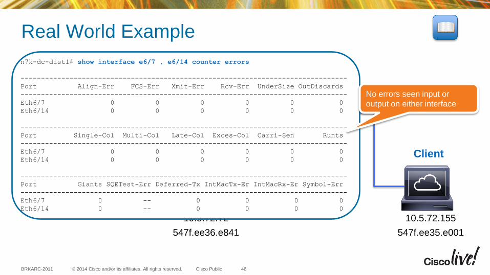
Real World Example
46
10.5.72.155
547f.ee35.e001
10.5.72.72
547f.ee36.e841
Server Client
Eth6/14 Eth6/7
n7k-dc-dist1# show interface e6/7 , e6/14 counter errors
--------------------------------------------------------------------------------
Port Align-Err FCS-Err Xmit-Err Rcv-Err UnderSize OutDiscards
--------------------------------------------------------------------------------
Eth6/7 0 0 0 0 0 0
Eth6/14 0 0 0 0 0 0
--------------------------------------------------------------------------------
Port Single-Col Multi-Col Late-Col Exces-Col Carri-Sen Runts
--------------------------------------------------------------------------------
Eth6/7 0 0 0 0 0 0
Eth6/14 0 0 0 0 0 0
--------------------------------------------------------------------------------
Port Giants SQETest-Err Deferred-Tx IntMacTx-Er IntMacRx-Er Symbol-Err
--------------------------------------------------------------------------------
Eth6/7 0 -- 0 0 0 0
Eth6/14 0 -- 0 0 0 0
No errors seen input or
output on either interface
© 2014 Cisco and/or its affiliates. All rights reserved. BRKARC-2011 Cisco Public
Real World Example Slow Download Rate
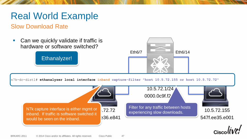
47
Can we quickly validate if traffic is hardware or software switched?
10.5.72.155
547f.ee35.e001
10.5.72.72
547f.ee36.e841
Server Client
Eth6/14 Eth6/7
SVI 572
10.5.72.1/24
0000.0c9f.f23c
Ethanalyzer!
n7k-dc-dist1# ethanalyzer local interface inband capture-filter "host 10.5.72.155 or host 10.5.72.72"
N7k capture interface is either mgmt or
inband. If traffic is software switched it
would be seen on the inband.
Filter for any traffic between hosts
experiencing slow downloads.
© 2014 Cisco and/or its affiliates. All rights reserved. BRKARC-2011 Cisco Public
Real World Example Slow Download Rate
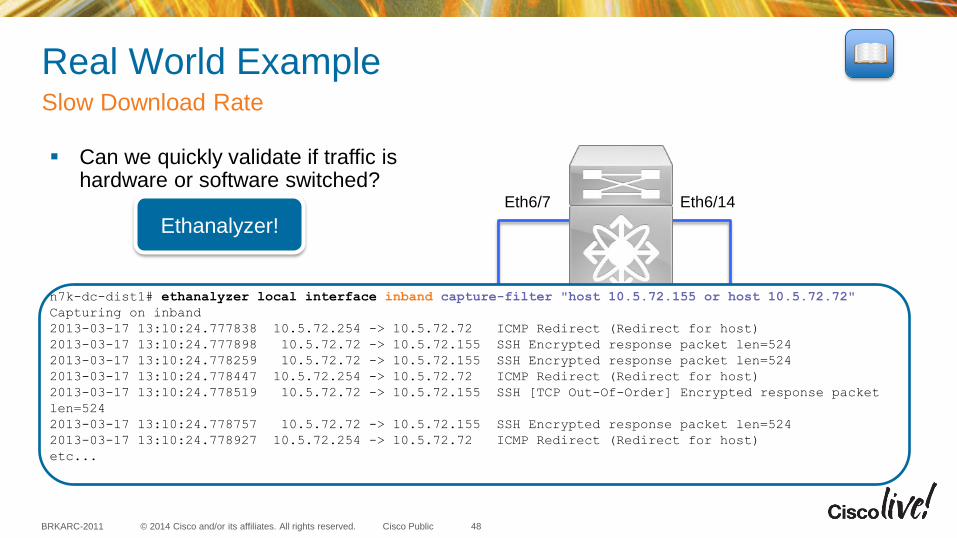
48
Can we quickly validate if traffic is hardware or software switched?
10.5.72.155
547f.ee35.e001
10.5.72.72
547f.ee36.e841
Server Client
Eth6/14 Eth6/7
SVI 572
10.5.72.1/24
0000.0c9f.f23c
Ethanalyzer!
n7k-dc-dist1# ethanalyzer local interface inband capture-filter "host 10.5.72.155 or host 10.5.72.72"
Capturing on inband
2013-03-17 13:10:24.777838 10.5.72.254 -> 10.5.72.72 ICMP Redirect (Redirect for host)
2013-03-17 13:10:24.777898 10.5.72.72 -> 10.5.72.155 SSH Encrypted response packet len=524
2013-03-17 13:10:24.778259 10.5.72.72 -> 10.5.72.155 SSH Encrypted response packet len=524
2013-03-17 13:10:24.778447 10.5.72.254 -> 10.5.72.72 ICMP Redirect (Redirect for host)
2013-03-17 13:10:24.778519 10.5.72.72 -> 10.5.72.155 SSH [TCP Out-Of-Order] Encrypted response packet
len=524
2013-03-17 13:10:24.778757 10.5.72.72 -> 10.5.72.155 SSH Encrypted response packet len=524
2013-03-17 13:10:24.778927 10.5.72.254 -> 10.5.72.72 ICMP Redirect (Redirect for host)
etc...
© 2014 Cisco and/or its affiliates. All rights reserved. BRKARC-2011 Cisco Public
Real World Example Slow Download Rate
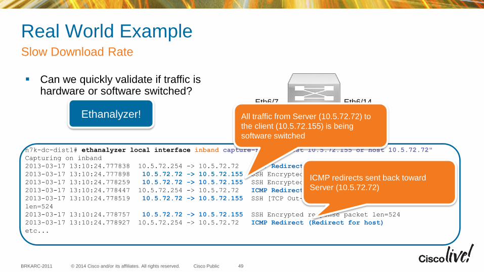
49
Can we quickly validate if traffic is hardware or software switched?
10.5.72.155
547f.ee35.e001
10.5.72.72
547f.ee36.e841
Server Client
Eth6/14 Eth6/7
SVI 572
10.5.72.1/24
0000.0c9f.f23c
Ethanalyzer!
n7k-dc-dist1# ethanalyzer local interface inband capture-filter "host 10.5.72.155 or host 10.5.72.72"
Capturing on inband
2013-03-17 13:10:24.777838 10.5.72.254 -> 10.5.72.72 ICMP Redirect (Redirect for host)
2013-03-17 13:10:24.777898 10.5.72.72 -> 10.5.72.155 SSH Encrypted response packet len=524
2013-03-17 13:10:24.778259 10.5.72.72 -> 10.5.72.155 SSH Encrypted response packet len=524
2013-03-17 13:10:24.778447 10.5.72.254 -> 10.5.72.72 ICMP Redirect (Redirect for host)
2013-03-17 13:10:24.778519 10.5.72.72 -> 10.5.72.155 SSH [TCP Out-Of-Order] Encrypted response packet
len=524
2013-03-17 13:10:24.778757 10.5.72.72 -> 10.5.72.155 SSH Encrypted response packet len=524
2013-03-17 13:10:24.778927 10.5.72.254 -> 10.5.72.72 ICMP Redirect (Redirect for host)
etc...
All traffic from Server (10.5.72.72) to
the client (10.5.72.155) is being
software switched
ICMP redirects sent back toward
Server (10.5.72.72)

© 2014 Cisco and/or its affiliates. All rights reserved. BRKARC-2011 Cisco Public
Real World Example Slow Download Rate
50
Can we quickly validate if traffic is hardware or software switched?
10.5.72.155
547f.ee35.e001
10.5.72.72
547f.ee36.e841
Server Client
Eth6/14 Eth6/7
SVI 572
10.5.72.1/24
0000.0c9f.f23c
Ethanalyzer!
n7k-dc-dist1# ethanalyzer local interface inband capture-filter "host 10.5.72.72" limit-captured-frames 1
detail | i Ethernet|Internet
Capturing on inband
1 packet captured
Ethernet II, Src: 54:7f:ee:36:e8:41 (54:7f:ee:36:e8:41), Dst: 00:00:0c:9f:f2:3c (00:00:0c:9f:f2:3c)
Internet Protocol, Src: 10.5.72.72 (10.5.72.72), Dst: 10.5.72.155 (10.5.72.155)
These hosts are in the same VLAN yet the
Server (10.5.72.72) is sending traffic
destined to the gateway’s MAC address
© 2014 Cisco and/or its affiliates. All rights reserved. BRKARC-2011 Cisco Public
Real World Example Slow Download Rate
51
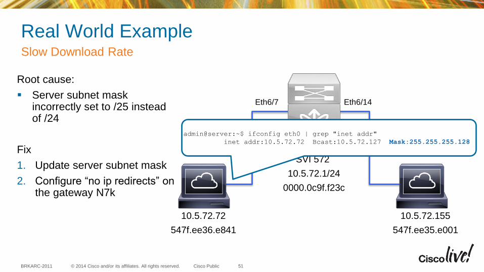
Root cause:
Server subnet mask incorrectly set to /25 instead of /24
Fix
1. Update server subnet mask
2. Configure “no ip redirects” on the gateway N7k
10.5.72.155
547f.ee35.e001
10.5.72.72
547f.ee36.e841
Server Client
Eth6/14 Eth6/7
SVI 572
10.5.72.1/24
0000.0c9f.f23c
admin@server:~$ ifconfig eth0 | grep "inet addr"
inet addr:10.5.72.72 Bcast:10.5.72.127 Mask:255.255.255.128
© 2014 Cisco and/or its affiliates. All rights reserved. BRKARC-2011 Cisco Public
Agenda
• Introduction
• Capturing Packets at the Control Plane
• Capturing Packets at the Data Plane
• Tips and Tricks
• Putting it All Together
• Q&A
52
SPAN – Switch Port Analyzer
© 2014 Cisco and/or its affiliates. All rights reserved. BRKARC-2011 Cisco Public
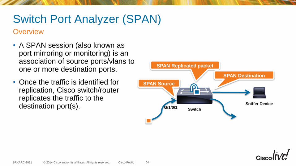
Switch Port Analyzer (SPAN)
• A SPAN session (also known as port mirroring or monitoring) is an association of source ports/vlans to one or more destination ports.
• Once the traffic is identified for replication, Cisco switch/router replicates the traffic to the destination port(s).
Overview
54
Switch Gi1/0/1
SPAN Source
Sniffer Device
SPAN Replicated packet
SPAN Destination
© 2014 Cisco and/or its affiliates. All rights reserved. BRKARC-2011 Cisco Public
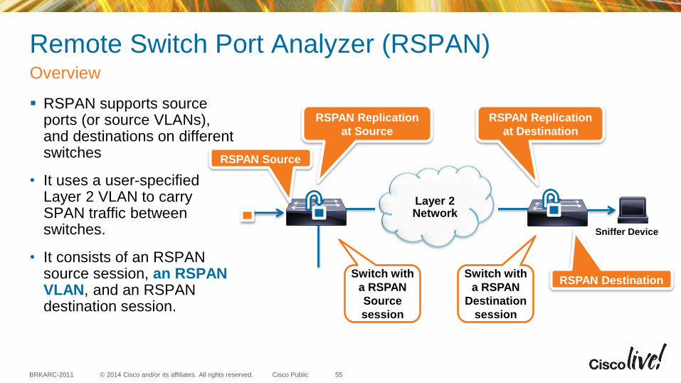
Remote Switch Port Analyzer (RSPAN)
RSPAN supports source ports (or source VLANs), and destinations on different switches
• It uses a user-specified Layer 2 VLAN to carry SPAN traffic between switches.
• It consists of an RSPAN source session, an RSPAN VLAN, and an RSPAN destination session.
Overview
55
RSPAN Source
Sniffer Device
RSPAN Replication
at Source
RSPAN Destination Switch with
a RSPAN
Source
session
Switch with
a RSPAN
Destination
session
RSPAN Replication
at Destination
Layer 2 Network
© 2014 Cisco and/or its affiliates. All rights reserved. BRKARC-2011 Cisco Public
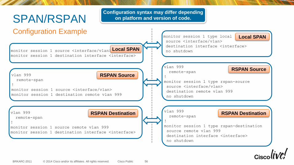
SPAN/RSPAN Configuration Example
monitor session 1 source <interface/vlan>
monitor session 1 destination interface <interface>
monitor session 1 type local
source <interface/vlan>
destination interface <interface>
no shutdown
vlan 999
remote-span
!
monitor session 1 source <interface/vlan>
monitor session 1 destination remote vlan 999
vlan 999
remote-span
!
monitor session 1 source remote vlan 999
monitor session 1 destination interface <interface>
vlan 999
remote-span
!
monitor session 1 type rspan-source
source <interface/vlan>
destination remote vlan 999
no shutdown
vlan 999
remote-span
!
monitor session 1 type rspan-destination
source remote vlan 999
destination interface <interface>
no shutdown
Configuration syntax may differ depending
on platform and version of code.
Local SPAN
Local SPAN
RSPAN Destination RSPAN Destination
RSPAN Source
RSPAN Source
56
© 2014 Cisco and/or its affiliates. All rights reserved. BRKARC-2011 Cisco Public
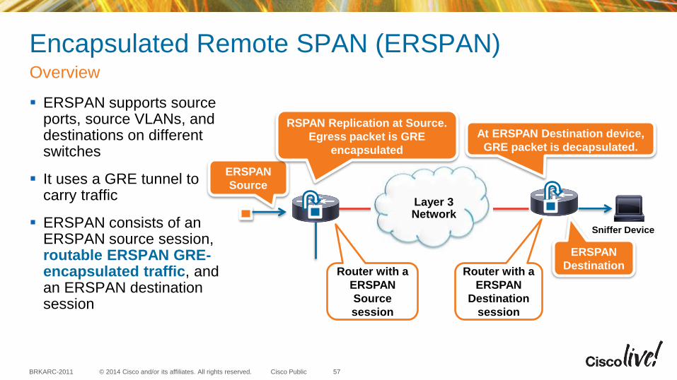
Encapsulated Remote SPAN (ERSPAN)
ERSPAN supports source ports, source VLANs, and destinations on different switches
It uses a GRE tunnel to carry traffic
ERSPAN consists of an ERSPAN source session, routable ERSPAN GRE-encapsulated traffic, and an ERSPAN destination session
Overview
57
ERSPAN
Source
Sniffer Device
RSPAN Replication at Source.
Egress packet is GRE
encapsulated
ERSPAN
Destination
Layer 3 Network
Router with a
ERSPAN
Source
session
Router with a
ERSPAN
Destination
session
At ERSPAN Destination device,
GRE packet is decapsulated.
© 2014 Cisco and/or its affiliates. All rights reserved. BRKARC-2011 Cisco Public
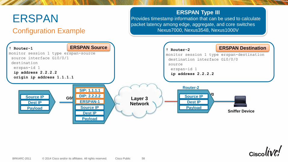
ERSPAN Configuration Example
! Router-2
monitor session 1 type erspan-destination
destination interface Gi0/0/0
source
erspan-id 1
ip address 2.2.2.2
ERSPAN Destination
Sniffer Device
Layer 3 Network
G0/0/1 G0/0/0
Router-1 Router-2
! Router-1
monitor session 1 type erspan-source
source interface Gi0/0/1
destination
erspan-id 1
ip address 2.2.2.2
origin ip address 1.1.1.1
ERSPAN Source
Source IP
Dest IP
Payload
Source IP
Dest IP
Payload Source IP
Dest IP
Payload
SIP: 1.1.1.1
DIP: 2.2.2.2
ERSPAN-1
58
ERSPAN Type III Provides timestamp information that can be used to calculate
packet latency among edge, aggregate, and core switches
Nexus7000, Nexus3548, Nexus1000V
© 2014 Cisco and/or its affiliates. All rights reserved. BRKARC-2011 Cisco Public
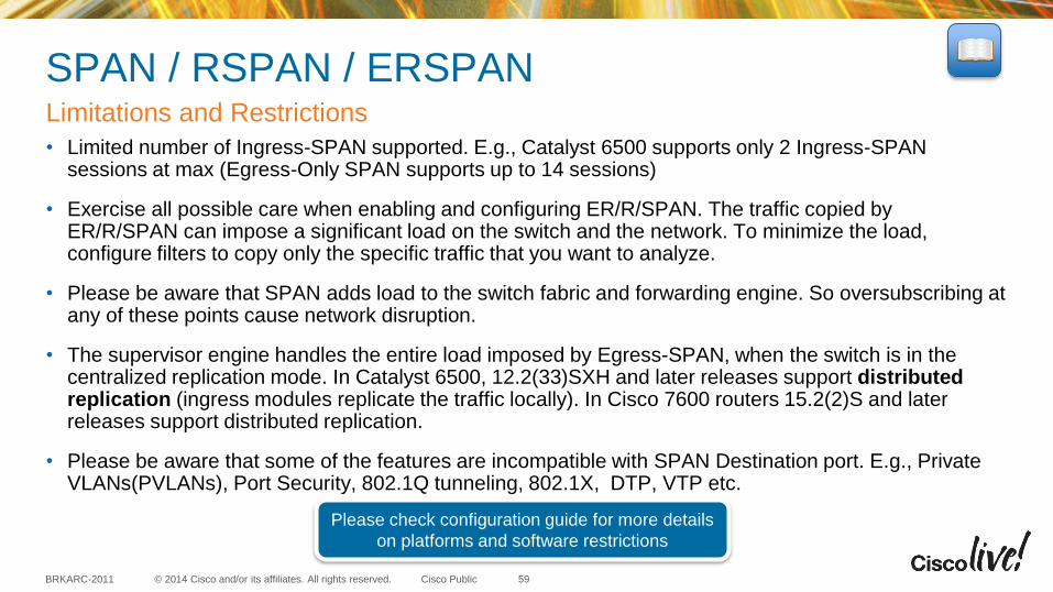
SPAN / RSPAN / ERSPAN
• Limited number of Ingress-SPAN supported. E.g., Catalyst 6500 supports only 2 Ingress-SPAN sessions at max (Egress-Only SPAN supports up to 14 sessions)
• Exercise all possible care when enabling and configuring ER/R/SPAN. The traffic copied by ER/R/SPAN can impose a significant load on the switch and the network. To minimize the load, configure filters to copy only the specific traffic that you want to analyze.
• Please be aware that SPAN adds load to the switch fabric and forwarding engine. So oversubscribing at any of these points cause network disruption.
• The supervisor engine handles the entire load imposed by Egress-SPAN, when the switch is in the centralized replication mode. In Catalyst 6500, 12.2(33)SXH and later releases support distributed replication (ingress modules replicate the traffic locally). In Cisco 7600 routers 15.2(2)S and later releases support distributed replication.
• Please be aware that some of the features are incompatible with SPAN Destination port. E.g., Private VLANs(PVLANs), Port Security, 802.1Q tunneling, 802.1X, DTP, VTP etc.
Limitations and Restrictions
59
Please check configuration guide for more details
on platforms and software restrictions
EPC, Embedded Wireshark, and MPA

© 2014 Cisco and/or its affiliates. All rights reserved. BRKARC-2011 Cisco Public
Embedded Packet Capture Tools
• Embedded Packet Capture (EPC)
• Embedded Wireshark
• Mini Protocol Analyzer (MPA)
61
These tools can also be used to capture
traffic at the control-plane level
© 2014 Cisco and/or its affiliates. All rights reserved. BRKARC-2011 Cisco Public
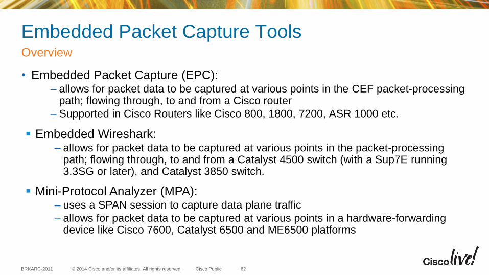
Embedded Packet Capture Tools
• Embedded Packet Capture (EPC): – allows for packet data to be captured at various points in the CEF packet-processing
path; flowing through, to and from a Cisco router
– Supported in Cisco Routers like Cisco 800, 1800, 7200, ASR 1000 etc.
Overview
62
Mini-Protocol Analyzer (MPA): – uses a SPAN session to capture data plane traffic
– allows for packet data to be captured at various points in a hardware-forwarding device like Cisco 7600, Catalyst 6500 and ME6500 platforms
Embedded Wireshark: – allows for packet data to be captured at various points in the packet-processing
path; flowing through, to and from a Catalyst 4500 switch (with a Sup7E running 3.3SG or later), and Catalyst 3850 switch.
© 2014 Cisco and/or its affiliates. All rights reserved. BRKARC-2011 Cisco Public
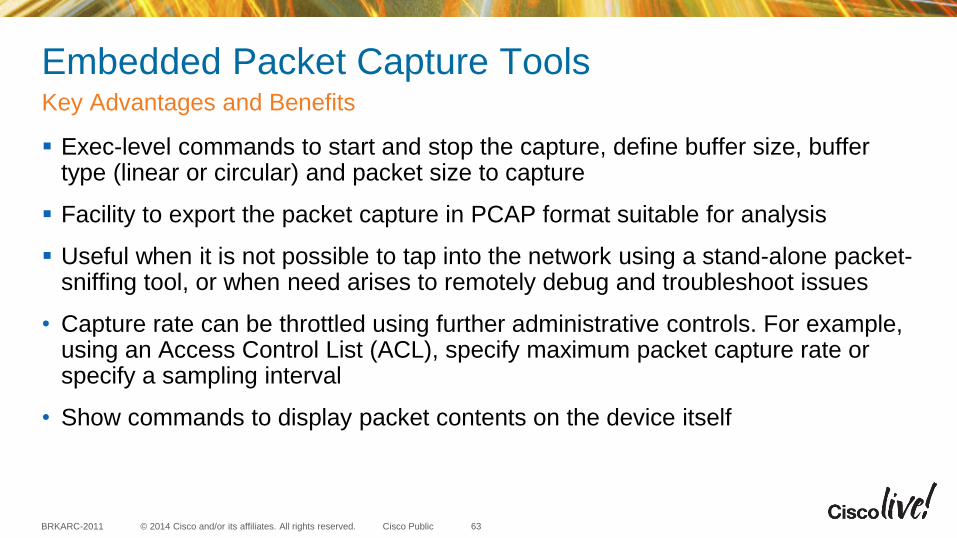
Embedded Packet Capture Tools
Exec-level commands to start and stop the capture, define buffer size, buffer type (linear or circular) and packet size to capture
Facility to export the packet capture in PCAP format suitable for analysis
Useful when it is not possible to tap into the network using a stand-alone packet-sniffing tool, or when need arises to remotely debug and troubleshoot issues
• Capture rate can be throttled using further administrative controls. For example, using an Access Control List (ACL), specify maximum packet capture rate or specify a sampling interval
• Show commands to display packet contents on the device itself
Key Advantages and Benefits
63

© 2014 Cisco and/or its affiliates. All rights reserved. BRKARC-2011 Cisco Public
Embedded Packet Capture (EPC) Configuration Steps
64
Steps to Configure:
1. Define capture buffer
2. Define capture point
3. Associate capture buffer and point (depends on the platform and OS ver)
4. Capture data
5. Export / display captured data
Capture point
Router# monitor capture MYCAP buffer circular packets 10000
Router# monitor capture MYCAP buffer size 10
Router# monitor capture MYCAP interface Gig0/0/1 in
Router# monitor capture MYCAP access-list MYACL
Router# monitor capture MYCAP start
Router# monitor capture MYCAP stop
Router# monitor capture MYCAP export bootflash:EPC1.pcap
Router# mon cap buffer MYBUF size 128 max-size 256 circular
Router# mon cap buffer MYBUF filter access-list MYACL
Router# mon cap point ip cef IPCEFCAP Gig0/0/1 both
Router# mon cap point associate IPCEFCAP MYBUF
Router# mon cap point start IPCEFCAP
Router# mon cap point stop IPCEFCAP
Router# mon cap buffer MYBUF export tftp://1.1.1.1/EPC1.pcap
In ASR 1002 running IOS-XE 15.3(2)S / 3.9(0)S release:
TFTP Server
Router
Capture Buffer
Gi0/0/1
Export Data
Capture point
older IOS versions on ISR platforms
Gi0/0/2
© 2014 Cisco and/or its affiliates. All rights reserved. BRKARC-2011 Cisco Public
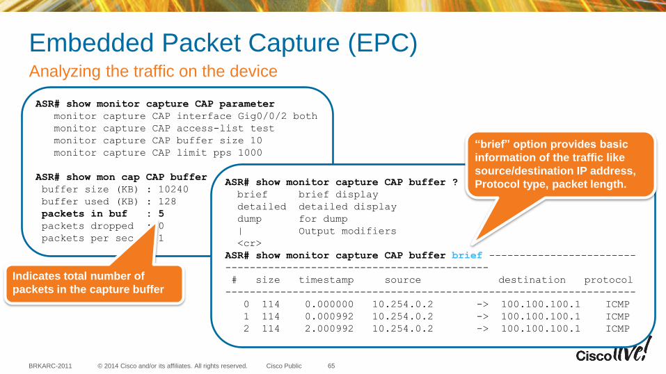
Embedded Packet Capture (EPC) Analyzing the traffic on the device
65
ASR# show monitor capture CAP parameter
monitor capture CAP interface Gig0/0/2 both
monitor capture CAP access-list test
monitor capture CAP buffer size 10
monitor capture CAP limit pps 1000
ASR# show mon cap CAP buffer
buffer size (KB) : 10240
buffer used (KB) : 128
packets in buf : 5
packets dropped : 0
packets per sec : 1
Indicates total number of
packets in the capture buffer
ASR# show monitor capture CAP buffer ?
brief brief display
detailed detailed display
dump for dump
| Output modifiers
<cr>
ASR# show monitor capture CAP buffer brief ------------------------
-------------------------------------------
# size timestamp source destination protocol
-------------------------------------------------------------------
0 114 0.000000 10.254.0.2 -> 100.100.100.1 ICMP
1 114 0.000992 10.254.0.2 -> 100.100.100.1 ICMP
2 114 2.000992 10.254.0.2 -> 100.100.100.1 ICMP
“brief” option provides basic
information of the traffic like
source/destination IP address,
Protocol type, packet length.
© 2014 Cisco and/or its affiliates. All rights reserved. BRKARC-2011 Cisco Public
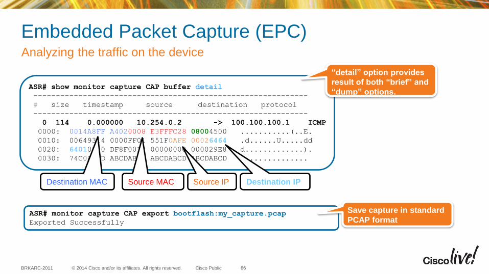
Embedded Packet Capture (EPC) Analyzing the traffic on the device
66
ASR# show monitor capture CAP buffer detail
-------------------------------------------------------------
# size timestamp source destination protocol
-------------------------------------------------------------
0 114 0.000000 10.254.0.2 -> 100.100.100.1 ICMP
0000: 0014A8FF A4020008 E3FFFC28 08004500 ...........(..E.
0010: 00649314 0000FF01 551F0AFE 00026464 .d......U.....dd
0020: 64010800 DF8F0012 00000000 000029E8 d.............).
0030: 74C0ABCD ABCDABCD ABCDABCD ABCDABCD t..............
“detail” option provides
result of both “brief” and
“dump” options.
Destination MAC Source MAC Source IP Destination IP
ASR# monitor capture CAP export bootflash:my_capture.pcap
Exported Successfully
Save capture in standard
PCAP format
© 2014 Cisco and/or its affiliates. All rights reserved. BRKARC-2011 Cisco Public
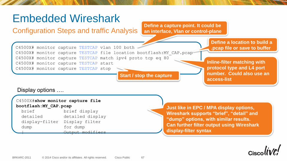
Embedded Wireshark Configuration Steps and traffic Analysis
67
C4500X# monitor capture TESTCAP vlan 100 both
C4500X# monitor capture TESTCAP file location bootflash:MY_CAP.pcap
C4500X# monitor capture TESTCAP match ipv4 proto tcp eq 80
C4500X# monitor capture TESTCAP start
C4500X# monitor capture TESTCAP stop
Define a capture point. It could be
an interface, Vlan or control-plane
Define a location to build a
.pcap file or save to buffer
Inline-filter matching with
protocol type and L4 port
number. Could also use an
access-list Start / stop the capture
C4500X#show monitor capture file
bootflash:MY_CAP.pcap
brief brief display
detailed detailed display
display-filter Display filter
dump for dump
| Output modifiers
Display options ….
Just like in EPC / MPA display options,
Wireshark supports “brief”, “detail” and
“dump” options, with similar results.
Can further filter output using Wireshark
display-filter syntax
© 2014 Cisco and/or its affiliates. All rights reserved. BRKARC-2011 Cisco Public
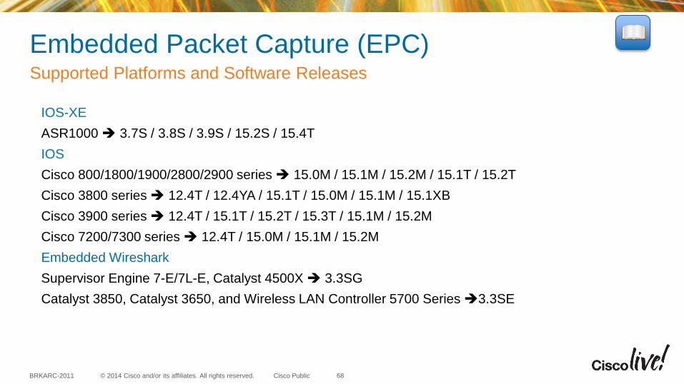
Embedded Packet Capture (EPC) Supported Platforms and Software Releases
68
IOS-XE
ASR1000 3.7S / 3.8S / 3.9S / 15.2S / 15.4T
IOS
Cisco 800/1800/1900/2800/2900 series 15.0M / 15.1M / 15.2M / 15.1T / 15.2T
Cisco 3800 series 12.4T / 12.4YA / 15.1T / 15.0M / 15.1M / 15.1XB
Cisco 3900 series 12.4T / 15.1T / 15.2T / 15.3T / 15.1M / 15.2M
Cisco 7200/7300 series 12.4T / 15.0M / 15.1M / 15.2M
Embedded Wireshark
Supervisor Engine 7-E/7L-E, Catalyst 4500X 3.3SG
Catalyst 3850, Catalyst 3650, and Wireless LAN Controller 5700 Series 3.3SE
© 2014 Cisco and/or its affiliates. All rights reserved. BRKARC-2011 Cisco Public
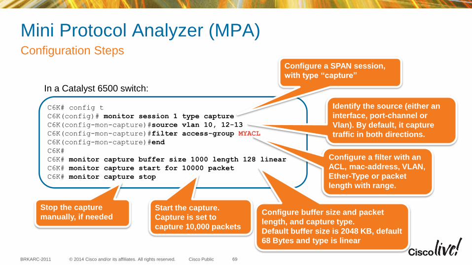
Mini Protocol Analyzer (MPA) Configuration Steps
69
C6K# config t
C6K(config)# monitor session 1 type capture
C6K(config-mon-capture)#source vlan 10, 12-13
C6K(config-mon-capture)#filter access-group MYACL
C6K(config-mon-capture)#end
C6K#
C6K# monitor capture buffer size 1000 length 128 linear
C6K# monitor capture start for 10000 packet
C6K# monitor capture stop
Configure a SPAN session,
with type “capture”
Identify the source (either an
interface, port-channel or
Vlan). By default, it capture
traffic in both directions.
Configure buffer size and packet
length, and capture type.
Default buffer size is 2048 KB, default
68 Bytes and type is linear
Configure a filter with an
ACL, mac-address, VLAN,
Ether-Type or packet
length with range.
Start the capture.
Capture is set to
capture 10,000 packets
Stop the capture
manually, if needed
In a Catalyst 6500 switch:
© 2014 Cisco and/or its affiliates. All rights reserved. BRKARC-2011 Cisco Public
Mini Protocol Analyzer (MPA) Analyzing the traffic on the device
70
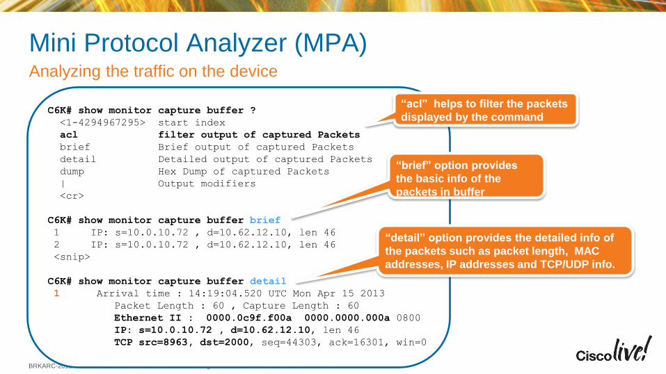
C6K# show monitor capture buffer ?
<1-4294967295> start index
acl filter output of captured Packets
brief Brief output of captured Packets
detail Detailed output of captured Packets
dump Hex Dump of captured Packets
| Output modifiers
<cr>
C6K# show monitor capture buffer brief
1 IP: s=10.0.10.72 , d=10.62.12.10, len 46
2 IP: s=10.0.10.72 , d=10.62.12.10, len 46
<snip>
C6K# show monitor capture buffer detail
1 Arrival time : 14:19:04.520 UTC Mon Apr 15 2013
Packet Length : 60 , Capture Length : 60
Ethernet II : 0000.0c9f.f00a 0000.0000.000a 0800
IP: s=10.0.10.72 , d=10.62.12.10, len 46
TCP src=8963, dst=2000, seq=44303, ack=16301, win=0
“brief” option provides
the basic info of the
packets in buffer
“detail” option provides the detailed info of
the packets such as packet length, MAC
addresses, IP addresses and TCP/UDP info.
“acl” helps to filter the packets
displayed by the command
© 2014 Cisco and/or its affiliates. All rights reserved. BRKARC-2011 Cisco Public
Mini Protocol Analyzer (MPA) Analyzing the traffic on the device
71
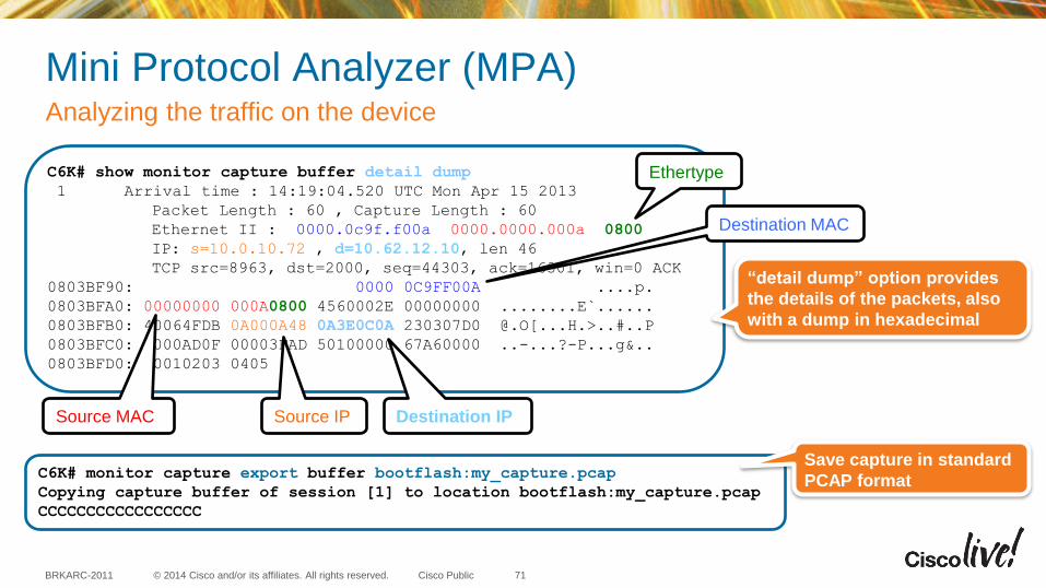
C6K# show monitor capture buffer detail dump
1 Arrival time : 14:19:04.520 UTC Mon Apr 15 2013
Packet Length : 60 , Capture Length : 60
Ethernet II : 0000.0c9f.f00a 0000.0000.000a 0800
IP: s=10.0.10.72 , d=10.62.12.10, len 46
TCP src=8963, dst=2000, seq=44303, ack=16301, win=0 ACK
0803BF90: 0000 0C9FF00A ....p.
0803BFA0: 00000000 000A0800 4560002E 00000000 ........E`......
0803BFB0: 40064FDB 0A000A48 0A3E0C0A 230307D0 @.O[...H.>..#..P
0803BFC0: 0000AD0F 00003FAD 50100000 67A60000 ..-...?-P...g&..
0803BFD0: 00010203 0405
Destination MAC
Source MAC
Ethertype
Source IP Destination IP
“detail dump” option provides
the details of the packets, also
with a dump in hexadecimal
C6K# monitor capture export buffer bootflash:my_capture.pcap
Copying capture buffer of session [1] to location bootflash:my_capture.pcap
CCCCCCCCCCCCCCCCC
Save capture in standard
PCAP format
© 2014 Cisco and/or its affiliates. All rights reserved. BRKARC-2011 Cisco Public
Mini Protocol Analyzer (MPA) Supported Platforms and Software Releases
72
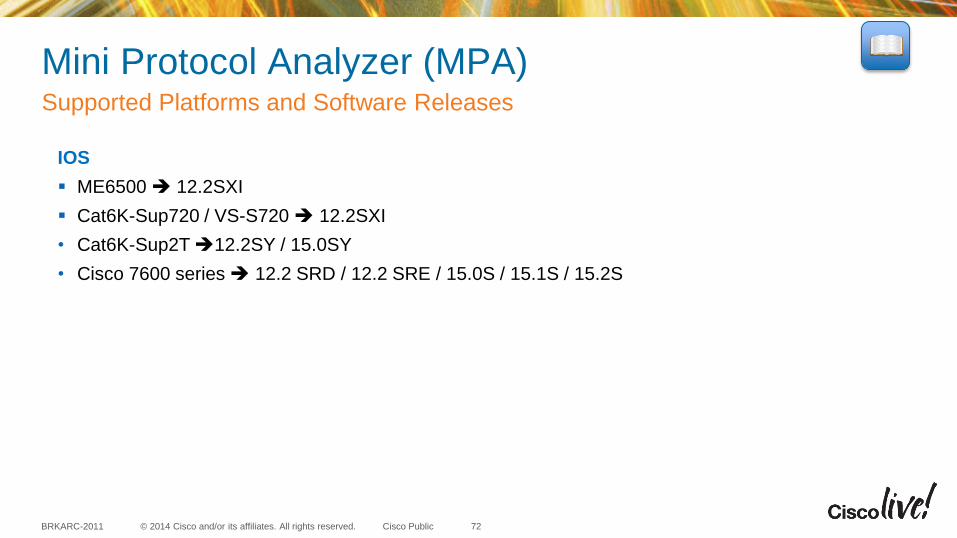
IOS
ME6500 12.2SXI
Cat6K-Sup720 / VS-S720 12.2SXI
• Cat6K-Sup2T 12.2SY / 15.0SY
• Cisco 7600 series 12.2 SRD / 12.2 SRE / 15.0S / 15.1S / 15.2S

© 2014 Cisco and/or its affiliates. All rights reserved. BRKARC-2011 Cisco Public
Embedded Packet Capture Tools
EPC:
This feature captures multicast traffic only on ingress, not the replicated packets on egress
In some of the Cisco platforms, EPC can be done only on one interface at a given time.
Mini Protocol Analyzer:
Only one session possible at any given time, and uses a SPAN session
To control the CPU usage, it is strongly recommended to use filters to limit the traffic to the CPU
Limitations and Restrictions – EPC / MPA
73
© 2014 Cisco and/or its affiliates. All rights reserved. BRKARC-2011 Cisco Public
Embedded Packet Capture Tools
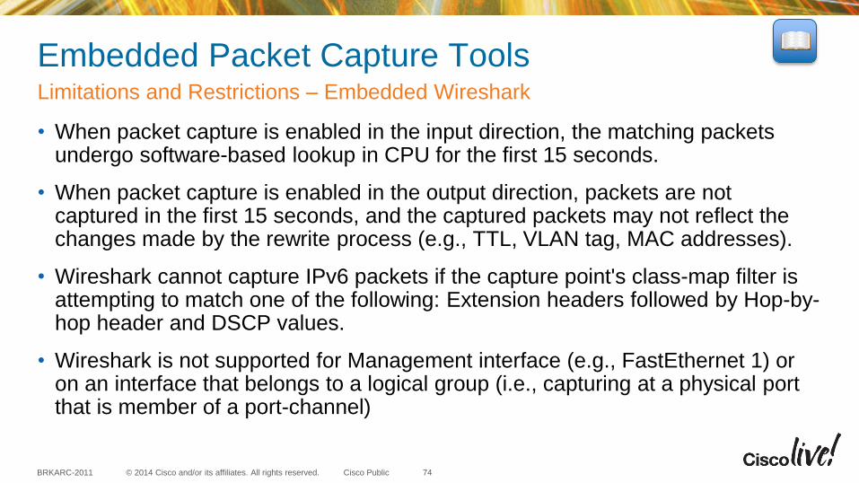
• When packet capture is enabled in the input direction, the matching packets undergo software-based lookup in CPU for the first 15 seconds.
• When packet capture is enabled in the output direction, packets are not captured in the first 15 seconds, and the captured packets may not reflect the changes made by the rewrite process (e.g., TTL, VLAN tag, MAC addresses).
• Wireshark cannot capture IPv6 packets if the capture point's class-map filter is attempting to match one of the following: Extension headers followed by Hop-by-hop header and DSCP values.
• Wireshark is not supported for Management interface (e.g., FastEthernet 1) or on an interface that belongs to a logical group (i.e., capturing at a physical port that is member of a port-channel)
Limitations and Restrictions – Embedded Wireshark
74
© 2014 Cisco and/or its affiliates. All rights reserved. BRKARC-2011 Cisco Public
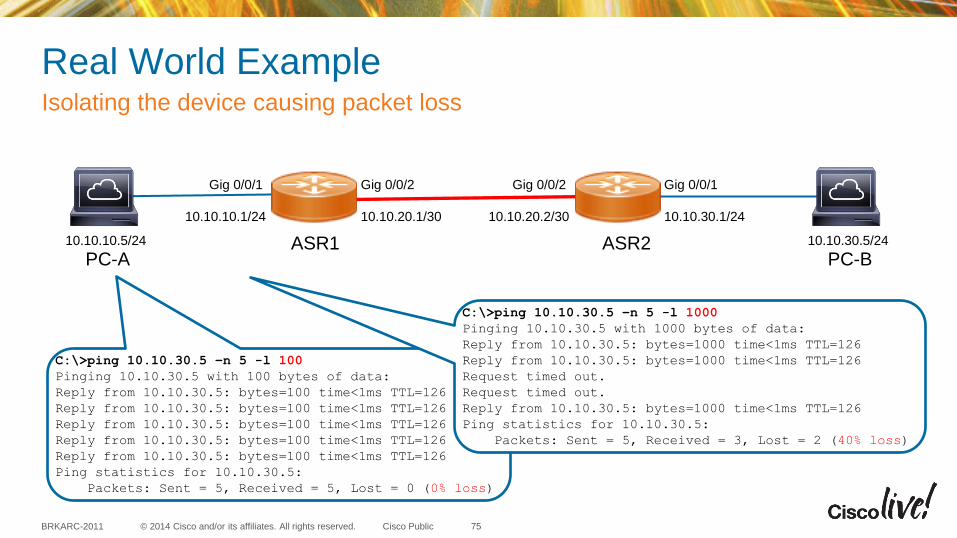
Real World Example Isolating the device causing packet loss
75
10.10.10.5/24
10.10.10.1/24 10.10.20.1/30 10.10.20.2/30 10.10.30.1/24
10.10.30.5/24 ASR1 ASR2 PC-A PC-B
C:\>ping 10.10.30.5 –n 5 -l 100
Pinging 10.10.30.5 with 100 bytes of data:
Reply from 10.10.30.5: bytes=100 time<1ms TTL=126
Reply from 10.10.30.5: bytes=100 time<1ms TTL=126
Reply from 10.10.30.5: bytes=100 time<1ms TTL=126
Reply from 10.10.30.5: bytes=100 time<1ms TTL=126
Reply from 10.10.30.5: bytes=100 time<1ms TTL=126
Ping statistics for 10.10.30.5:
Packets: Sent = 5, Received = 5, Lost = 0 (0% loss)
C:\>ping 10.10.30.5 –n 5 -l 1000
Pinging 10.10.30.5 with 1000 bytes of data:
Reply from 10.10.30.5: bytes=1000 time<1ms TTL=126
Reply from 10.10.30.5: bytes=1000 time<1ms TTL=126
Request timed out.
Request timed out.
Reply from 10.10.30.5: bytes=1000 time<1ms TTL=126
Ping statistics for 10.10.30.5:
Packets: Sent = 5, Received = 3, Lost = 2 (40% loss)
Gig 0/0/1 Gig 0/0/2 Gig 0/0/2 Gig 0/0/1
© 2014 Cisco and/or its affiliates. All rights reserved. BRKARC-2011 Cisco Public
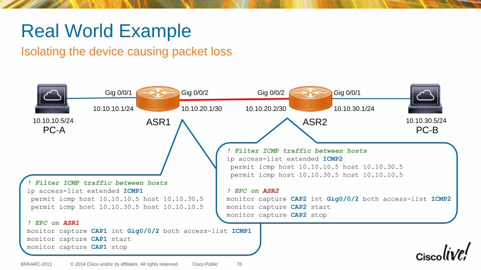
Real World Example Isolating the device causing packet loss
76
10.10.10.5/24
10.10.10.1/24 10.10.20.1/30 10.10.20.2/30 10.10.30.1/24
10.10.30.5/24 ASR1 ASR2 PC-A PC-B
Gig 0/0/1 Gig 0/0/2 Gig 0/0/2 Gig 0/0/1
! Filter ICMP traffic between hosts
ip access-list extended ICMP1
permit icmp host 10.10.10.5 host 10.10.30.5
permit icmp host 10.10.30.5 host 10.10.10.5
! EPC on ASR1
monitor capture CAP1 int Gig0/0/2 both access-list ICMP1
monitor capture CAP1 start
monitor capture CAP1 stop
! Filter ICMP traffic between hosts
ip access-list extended ICMP2
permit icmp host 10.10.10.5 host 10.10.30.5
permit icmp host 10.10.30.5 host 10.10.10.5
! EPC on ASR2
monitor capture CAP2 int Gig0/0/2 both access-list ICMP2
monitor capture CAP2 start
monitor capture CAP2 stop
© 2014 Cisco and/or its affiliates. All rights reserved. BRKARC-2011 Cisco Public
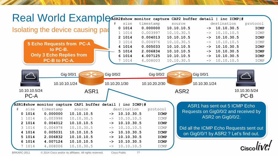
Real World Example Isolating the device causing packet loss
77
10.10.10.5/24
10.10.10.1/24 10.10.20.1/30 10.10.20.2/30 10.10.30.1/24
10.10.30.5/24 ASR1 ASR2 PC-A PC-B
Gig 0/0/1 Gig 0/0/2 Gig 0/0/2 Gig 0/0/1
ASR1#show monitor capture CAP1 buffer detail | inc ICMP|#
# size timestamp source destination protocol
0 1014 0.000000 10.10.10.5 -> 10.10.30.5 ICMP
1 1014 0.003998 10.10.30.5 -> 10.10.10.5 ICMP
2 1014 0.004012 10.10.10.5 -> 10.10.30.5 ICMP
3 1014 0.004978 10.10.30.5 -> 10.10.10.5 ICMP
4 1014 0.005031 10.10.10.5 -> 10.10.30.5 ICMP
5 1014 2.006832 10.10.10.5 -> 10.10.30.5 ICMP
6 1014 4.007124 10.10.10.5 -> 10.10.30.5 ICMP
7 1014 4.008006 10.10.30.5 -> 10.10.10.5 ICMP
ASR2#show monitor capture CAP2 buffer detail | inc ICMP|#
# size timestamp source destination protocol
0 1014 0.000000 10.10.10.5 -> 10.10.30.5 ICMP
1 1014 0.003997 10.10.30.5 -> 10.10.10.5 ICMP
2 1014 0.004013 10.10.10.5 -> 10.10.30.5 ICMP
3 1014 0.004976 10.10.30.5 -> 10.10.10.5 ICMP
4 1014 0.005033 10.10.10.5 -> 10.10.30.5 ICMP
5 1014 2.006834 10.10.10.5 -> 10.10.30.5 ICMP
6 1014 4.007125 10.10.10.5 -> 10.10.30.5 ICMP
7 1014 4.008003 10.10.30.5 -> 10.10.10.5 ICMP
ASR1 has sent out 5 ICMP Echo
Requests on Gig0/0/2 and received by
ASR2 on Gig0/0/2.
Did all the ICMP Echo Requests sent out
on Gig0/0/1 by ASR2 ? Let’s find out.
5 Echo Requests from PC-A
to PC-B.
Only 3 Echo Replies from
PC-B to PC-A.
© 2014 Cisco and/or its affiliates. All rights reserved. BRKARC-2011 Cisco Public
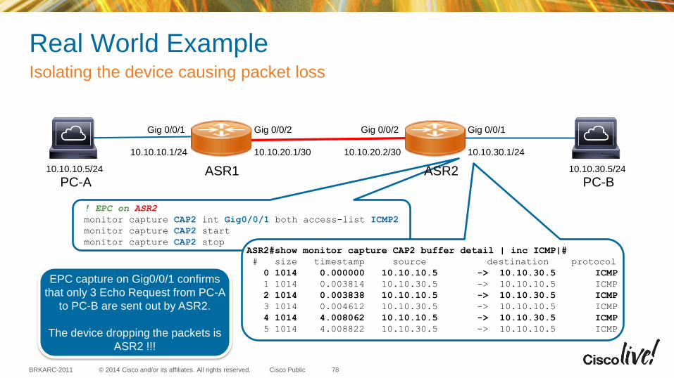
Real World Example Isolating the device causing packet loss
78
10.10.10.5/24
10.10.10.1/24 10.10.20.1/30 10.10.20.2/30 10.10.30.1/24
10.10.30.5/24 ASR1 PC-A PC-B
Gig 0/0/1 Gig 0/0/2 Gig 0/0/2 Gig 0/0/1
! EPC on ASR2
monitor capture CAP2 int Gig0/0/1 both access-list ICMP2
monitor capture CAP2 start
monitor capture CAP2 stop ASR2#show monitor capture CAP2 buffer detail | inc ICMP|#
# size timestamp source destination protocol
0 1014 0.000000 10.10.10.5 -> 10.10.30.5 ICMP
1 1014 0.003814 10.10.30.5 -> 10.10.10.5 ICMP
2 1014 0.003838 10.10.10.5 -> 10.10.30.5 ICMP
3 1014 0.004612 10.10.30.5 -> 10.10.10.5 ICMP
4 1014 4.008062 10.10.10.5 -> 10.10.30.5 ICMP
5 1014 4.008822 10.10.30.5 -> 10.10.10.5 ICMP
EPC capture on Gig0/0/1 confirms
that only 3 Echo Request from PC-A
to PC-B are sent out by ASR2.
The device dropping the packets is
ASR2 !!!
ASR2
© 2014 Cisco and/or its affiliates. All rights reserved. BRKARC-2011 Cisco Public
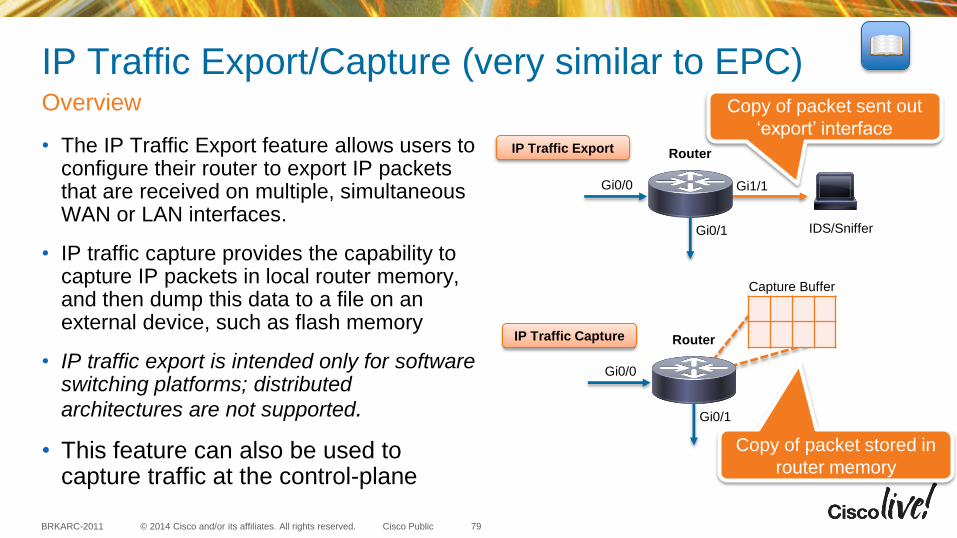
IP Traffic Export/Capture (very similar to EPC)
• The IP Traffic Export feature allows users to configure their router to export IP packets that are received on multiple, simultaneous WAN or LAN interfaces.
• IP traffic capture provides the capability to capture IP packets in local router memory, and then dump this data to a file on an external device, such as flash memory
• IP traffic export is intended only for software switching platforms; distributed
architectures are not supported.
• This feature can also be used to capture traffic at the control-plane
Overview
79
Router
Gi0/0
IDS/Sniffer Gi0/1
Router
Gi0/0
Gi0/1
Capture Buffer
Copy of packet sent out
‘export’ interface
Copy of packet stored in
router memory
IP Traffic Export
IP Traffic Capture
Gi1/1
© 2014 Cisco and/or its affiliates. All rights reserved. BRKARC-2011 Cisco Public
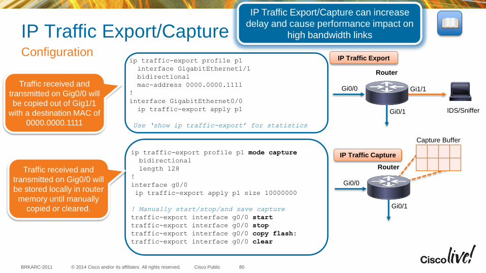
IP Traffic Export/Capture Configuration
80
Router
Gi0/0
IDS/Sniffer Gi0/1
Router
Gi0/0
Gi0/1
Capture Buffer
IP Traffic Export/Capture can increase
delay and cause performance impact on
high bandwidth links
ip traffic-export profile p1
interface GigabitEthernet1/1
bidirectional
mac-address 0000.0000.1111
!
interface GigabitEthernet0/0
ip traffic-export apply p1
Use ‘show ip traffic-export’ for statistics
Gi1/1
ip traffic-export profile p1 mode capture
bidirectional
length 128
!
interface g0/0
ip traffic-export apply p1 size 10000000
! Manually start/stop/and save capture
traffic-export interface g0/0 start
traffic-export interface g0/0 stop
traffic-export interface g0/0 copy flash:
traffic-export interface g0/0 clear
IP Traffic Export
IP Traffic Capture
Traffic received and
transmitted on Gig0/0 will
be copied out of Gig1/1
with a destination MAC of
0000.0000.1111
Traffic received and
transmitted on Gig0/0 will
be stored locally in router
memory until manually
copied or cleared.
FSPAN, VACL and ACL Capture
© 2014 Cisco and/or its affiliates. All rights reserved. BRKARC-2011 Cisco Public
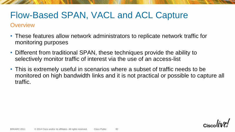
Flow-Based SPAN, VACL and ACL Capture
• These features allow network administrators to replicate network traffic for monitoring purposes
• Different from traditional SPAN, these techniques provide the ability to selectively monitor traffic of interest via the use of an access-list
• This is extremely useful in scenarios where a subset of traffic needs to be monitored on high bandwidth links and it is not practical or possible to capture all traffic.
Overview
82
© 2014 Cisco and/or its affiliates. All rights reserved. BRKARC-2011 Cisco Public
Flow-Based SPAN
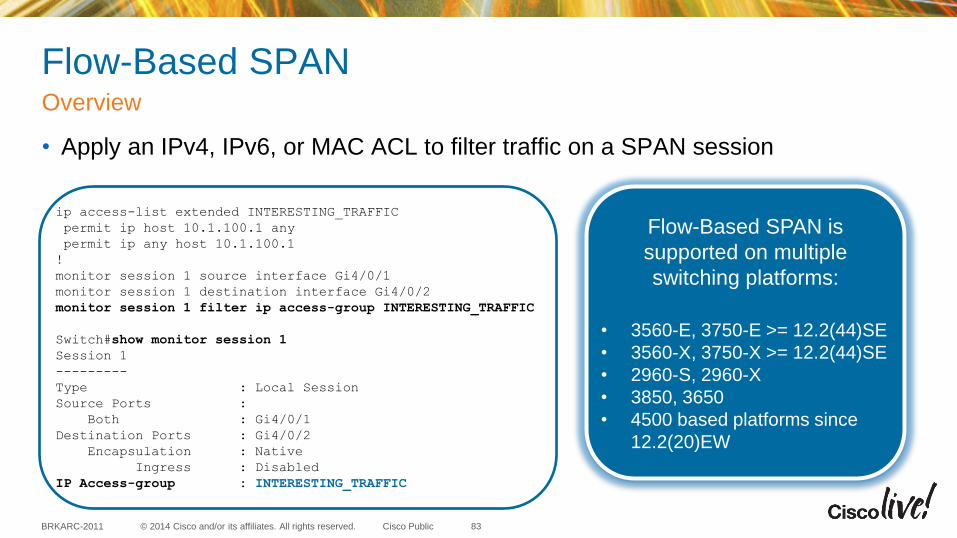
• Apply an IPv4, IPv6, or MAC ACL to filter traffic on a SPAN session
Overview
ip access-list extended INTERESTING_TRAFFIC
permit ip host 10.1.100.1 any
permit ip any host 10.1.100.1
!
monitor session 1 source interface Gi4/0/1
monitor session 1 destination interface Gi4/0/2
monitor session 1 filter ip access-group INTERESTING_TRAFFIC
Switch#show monitor session 1
Session 1
---------
Type : Local Session
Source Ports :
Both : Gi4/0/1
Destination Ports : Gi4/0/2
Encapsulation : Native
Ingress : Disabled
IP Access-group : INTERESTING_TRAFFIC
Flow-Based SPAN is
supported on multiple
switching platforms:
• 3560-E, 3750-E >= 12.2(44)SE
• 3560-X, 3750-X >= 12.2(44)SE
• 2960-S, 2960-X
• 3850, 3650
• 4500 based platforms since
12.2(20)EW
83
© 2014 Cisco and/or its affiliates. All rights reserved. BRKARC-2011 Cisco Public
VACL Capture
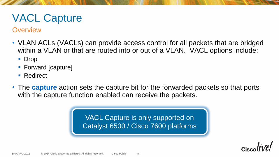
• VLAN ACLs (VACLs) can provide access control for all packets that are bridged within a VLAN or that are routed into or out of a VLAN. VACL options include:
Drop
Forward [capture]
Redirect
• The capture action sets the capture bit for the forwarded packets so that ports with the capture function enabled can receive the packets.
Overview
84
VACL Capture is only supported on
Catalyst 6500 / Cisco 7600 platforms
© 2014 Cisco and/or its affiliates. All rights reserved. BRKARC-2011 Cisco Public
VACL Capture Configuration
85
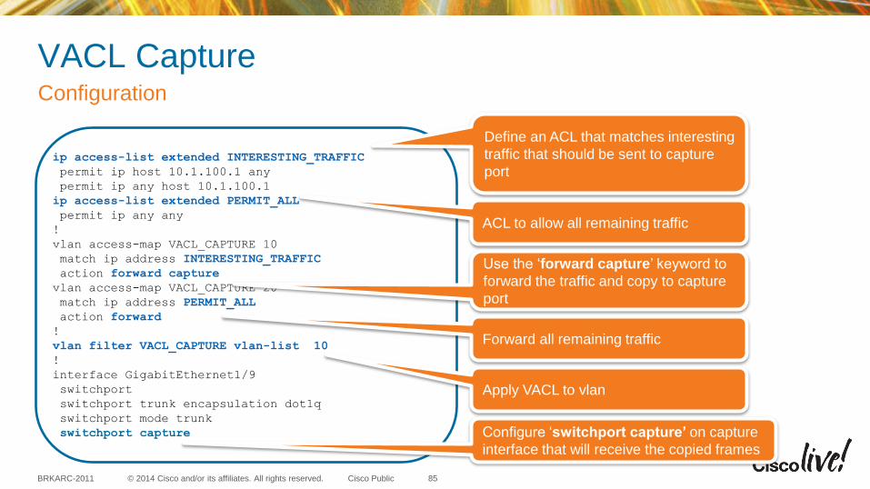
ip access-list extended INTERESTING_TRAFFIC
permit ip host 10.1.100.1 any
permit ip any host 10.1.100.1
ip access-list extended PERMIT_ALL
permit ip any any
!
vlan access-map VACL_CAPTURE 10
match ip address INTERESTING_TRAFFIC
action forward capture
vlan access-map VACL_CAPTURE 20
match ip address PERMIT_ALL
action forward
!
vlan filter VACL_CAPTURE vlan-list 10
!
interface GigabitEthernet1/9
switchport
switchport trunk encapsulation dot1q
switchport mode trunk
switchport capture
Define an ACL that matches interesting
traffic that should be sent to capture
port
ACL to allow all remaining traffic
Use the ‘forward capture’ keyword to
forward the traffic and copy to capture
port
Forward all remaining traffic
Apply VACL to vlan
Configure ‘switchport capture’ on capture
interface that will receive the copied frames
© 2014 Cisco and/or its affiliates. All rights reserved. BRKARC-2011 Cisco Public
ACL Capture
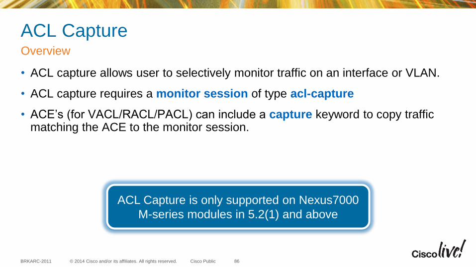
• ACL capture allows user to selectively monitor traffic on an interface or VLAN.
• ACL capture requires a monitor session of type acl-capture
• ACE’s (for VACL/RACL/PACL) can include a capture keyword to copy traffic matching the ACE to the monitor session.
Overview
86
ACL Capture is only supported on Nexus7000
M-series modules in 5.2(1) and above
© 2014 Cisco and/or its affiliates. All rights reserved. BRKARC-2011 Cisco Public
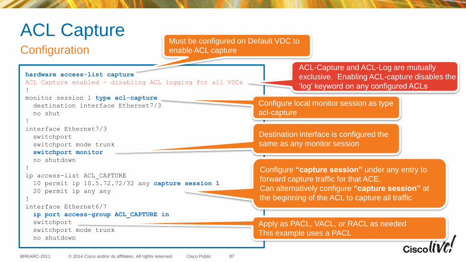
ACL Capture Configuration
87
hardware access-list capture
ACL Capture enabled - disabling ACL logging for all VDCs
!
monitor session 1 type acl-capture
destination interface Ethernet7/3
no shut
!
interface Ethernet7/3
switchport
switchport mode trunk
switchport monitor
no shutdown
!
ip access-list ACL_CAPTURE
10 permit ip 10.5.72.72/32 any capture session 1
20 permit ip any any
!
interface Ethernet6/7
ip port access-group ACL_CAPTURE in
switchport
switchport mode trunk
no shutdown
Must be configured on Default VDC to
enable ACL capture
Configure local monitor session as type
acl-capture
Destination interface is configured the
same as any monitor session
Configure “capture session” under any entry to
forward capture traffic for that ACE.
Can alternatively configure “capture session” at
the beginning of the ACL to capture all traffic
Apply as PACL, VACL, or RACL as needed
This example uses a PACL
ACL-Capture and ACL-Log are mutually
exclusive. Enabling ACL-capture disables the
‘log’ keyword on any configured ACLs
© 2014 Cisco and/or its affiliates. All rights reserved. BRKARC-2011 Cisco Public
ACL Capture
• ACL Capture is only supported on Nexus7000 M-series modules in 5.2(1) and above
• Enabling ACL Capture disables ACL Logging
• Multiple ACL Capture SPAN sessions can be configured but only one ACL Capture session will be active at a time on the system across all VDCs.
• The ACL policy with capture rules can be applied in ingress direction on all interfaces
• The ACL policy with capture rules can be applied in egress direction on all L3 interfaces
Limitations and Restrictions
88
© 2014 Cisco and/or its affiliates. All rights reserved. BRKARC-2011 Cisco Public
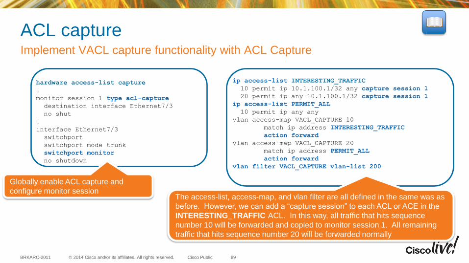
ACL capture Implement VACL capture functionality with ACL Capture
89
hardware access-list capture
!
monitor session 1 type acl-capture
destination interface Ethernet7/3
no shut
!
interface Ethernet7/3
switchport
switchport mode trunk
switchport monitor
no shutdown
ip access-list INTERESTING_TRAFFIC
10 permit ip 10.1.100.1/32 any capture session 1
20 permit ip any 10.1.100.1/32 capture session 1
ip access-list PERMIT_ALL
10 permit ip any any
vlan access-map VACL_CAPTURE 10
match ip address INTERESTING_TRAFFIC
action forward
vlan access-map VACL_CAPTURE 20
match ip address PERMIT_ALL
action forward
vlan filter VACL_CAPTURE vlan-list 200
Globally enable ACL capture and
configure monitor session The access-list, access-map, and vlan filter are all defined in the same was as
before. However, we can add a “capture session” to each ACL or ACE in the
INTERESTING_TRAFFIC ACL. In this way, all traffic that hits sequence
number 10 will be forwarded and copied to monitor session 1. All remaining
traffic that hits sequence number 20 will be forwarded normally
© 2014 Cisco and/or its affiliates. All rights reserved. BRKARC-2011 Cisco Public
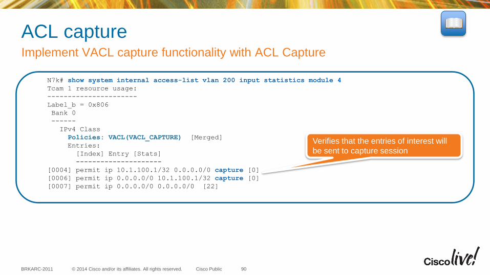
ACL capture Implement VACL capture functionality with ACL Capture
90
N7k# show system internal access-list vlan 200 input statistics module 4
Tcam 1 resource usage:
----------------------
Label_b = 0x806
Bank 0
------
IPv4 Class
Policies: VACL(VACL_CAPTURE) [Merged]
Entries:
[Index] Entry [Stats]
---------------------
[0004] permit ip 10.1.100.1/32 0.0.0.0/0 capture [0]
[0006] permit ip 0.0.0.0/0 10.1.100.1/32 capture [0]
[0007] permit ip 0.0.0.0/0 0.0.0.0/0 [22]
Verifies that the entries of interest will
be sent to capture session
ELAM – Embedded Logic Analyzer Module

© 2014 Cisco and/or its affiliates. All rights reserved. BRKARC-2011 Cisco Public
ELAM
• Embedded Logic Analyzer Module (ELAM) is an engineering tool that is used to look inside Cisco ASICs.
• ELAM is architecture specific and therefore will have different capabilities and different CLI syntax across different forwarding engines (FE).
• Identifying the appropriate FE, creating triggers, and interpreting ELAM data for complex flows requires full architectural and forwarding knowledge
Overview and Challenges
92
ELAM is NOT a supported feature. It is a diagnostic tool designed for
internal use. Anything and everything about it may change from version to
version without any notice
© 2014 Cisco and/or its affiliates. All rights reserved. BRKARC-2011 Cisco Public
ELAM
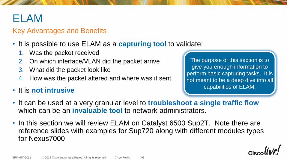
• It is possible to use ELAM as a capturing tool to validate:
1. Was the packet received
2. On which interface/VLAN did the packet arrive
3. What did the packet look like
4. How was the packet altered and where was it sent
• It is not intrusive
• It can be used at a very granular level to troubleshoot a single traffic flow which can be an invaluable tool to network administrators.
• In this section we will review ELAM on Catalyst 6500 Sup2T. Note there are reference slides with examples for Sup720 along with different modules types for Nexus7000
Key Advantages and Benefits
93
The purpose of this section is to
give you enough information to
perform basic capturing tasks. It is
not meant to be a deep dive into all
capabilities of ELAM.
© 2014 Cisco and/or its affiliates. All rights reserved. BRKARC-2011 Cisco Public
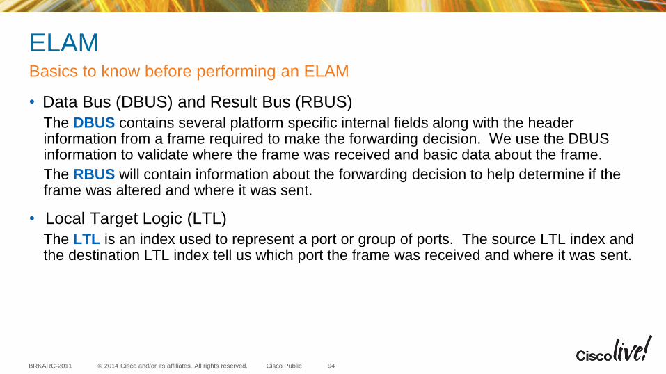
ELAM
• Data Bus (DBUS) and Result Bus (RBUS)
The DBUS contains several platform specific internal fields along with the header information from a frame required to make the forwarding decision. We use the DBUS information to validate where the frame was received and basic data about the frame.
The RBUS will contain information about the forwarding decision to help determine if the frame was altered and where it was sent.
• Local Target Logic (LTL)
The LTL is an index used to represent a port or group of ports. The source LTL index and the destination LTL index tell us which port the frame was received and where it was sent.
Basics to know before performing an ELAM
94
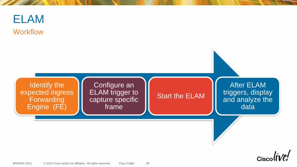
© 2014 Cisco and/or its affiliates. All rights reserved. BRKARC-2011 Cisco Public
ELAM Workflow
95
Identify the expected ingress
Forwarding Engine (FE)
Configure an ELAM trigger to capture specific
frame
Start the ELAM
After ELAM triggers, display and analyze the
data
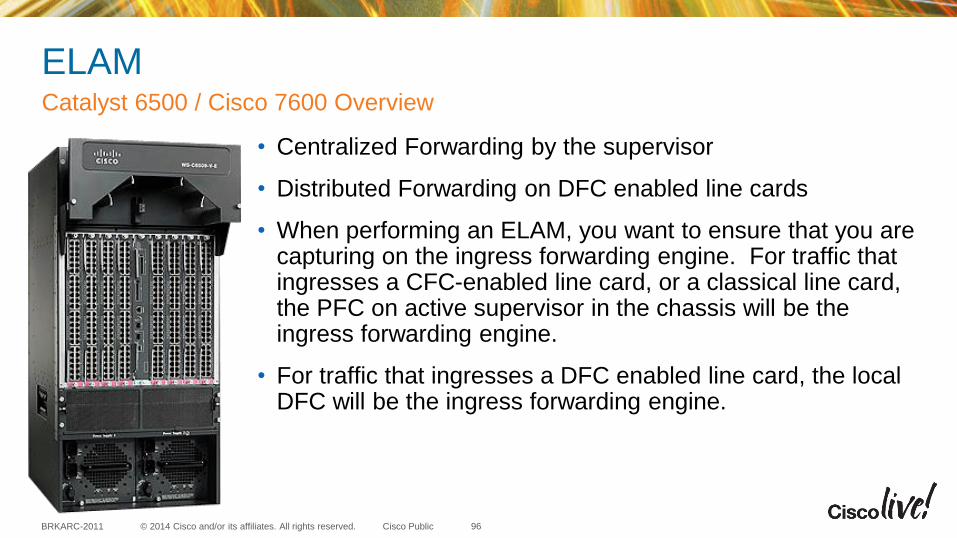
© 2014 Cisco and/or its affiliates. All rights reserved. BRKARC-2011 Cisco Public
ELAM
• Centralized Forwarding by the supervisor
• Distributed Forwarding on DFC enabled line cards
• When performing an ELAM, you want to ensure that you are capturing on the ingress forwarding engine. For traffic that ingresses a CFC-enabled line card, or a classical line card, the PFC on active supervisor in the chassis will be the ingress forwarding engine.
• For traffic that ingresses a DFC enabled line card, the local DFC will be the ingress forwarding engine.
Catalyst 6500 / Cisco 7600 Overview
96
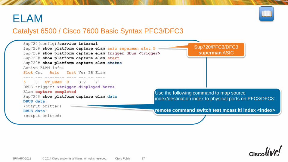
© 2014 Cisco and/or its affiliates. All rights reserved. BRKARC-2011 Cisco Public
ELAM Catalyst 6500 / Cisco 7600 Basic Syntax PFC3/DFC3
97
Sup720(config)#service internal
Sup720# show platform capture elam asic superman slot 5
Sup720# show platform capture elam trigger dbus <trigger>
Sup720# show platform capture elam start
Sup720# show platform capture elam status
Active ELAM info:
Slot Cpu Asic Inst Ver PB Elam
---- --- -------- ---- --- -- ----
5 0 ST_SMAN 0 3.2 Y
DBUS trigger: <trigger displayed here>
Elam capture completed
Sup720# show platform capture elam data
DBUS data:
(output omitted)
RBUS data:
(output omitted)
Sup720/PFC3/DFC3
superman ASIC
Use the following command to map source
index/destination index to physical ports on PFC3/DFC3:
remote command switch test mcast ltl index <index>
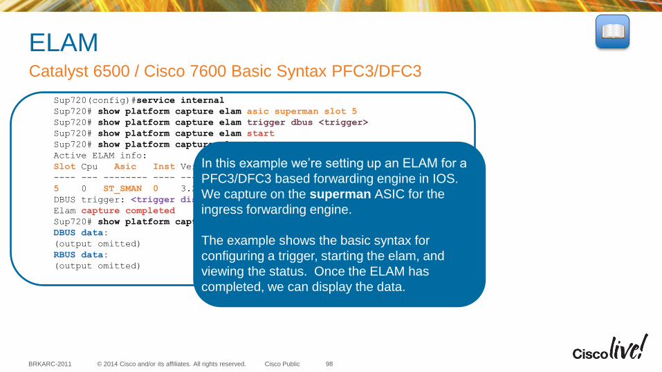
© 2014 Cisco and/or its affiliates. All rights reserved. BRKARC-2011 Cisco Public
ELAM Catalyst 6500 / Cisco 7600 Basic Syntax PFC3/DFC3
98
Sup720(config)#service internal
Sup720# show platform capture elam asic superman slot 5
Sup720# show platform capture elam trigger dbus <trigger>
Sup720# show platform capture elam start
Sup720# show platform capture elam status
Active ELAM info:
Slot Cpu Asic Inst Ver PB Elam
---- --- -------- ---- --- -- ----
5 0 ST_SMAN 0 3.2 Y
DBUS trigger: <trigger displayed here>
Elam capture completed
Sup720# show platform capture elam data
DBUS data:
(output omitted)
RBUS data:
(output omitted)
In this example we’re setting up an ELAM for a
PFC3/DFC3 based forwarding engine in IOS.
We capture on the superman ASIC for the
ingress forwarding engine.
The example shows the basic syntax for
configuring a trigger, starting the elam, and
viewing the status. Once the ELAM has
completed, we can display the data.
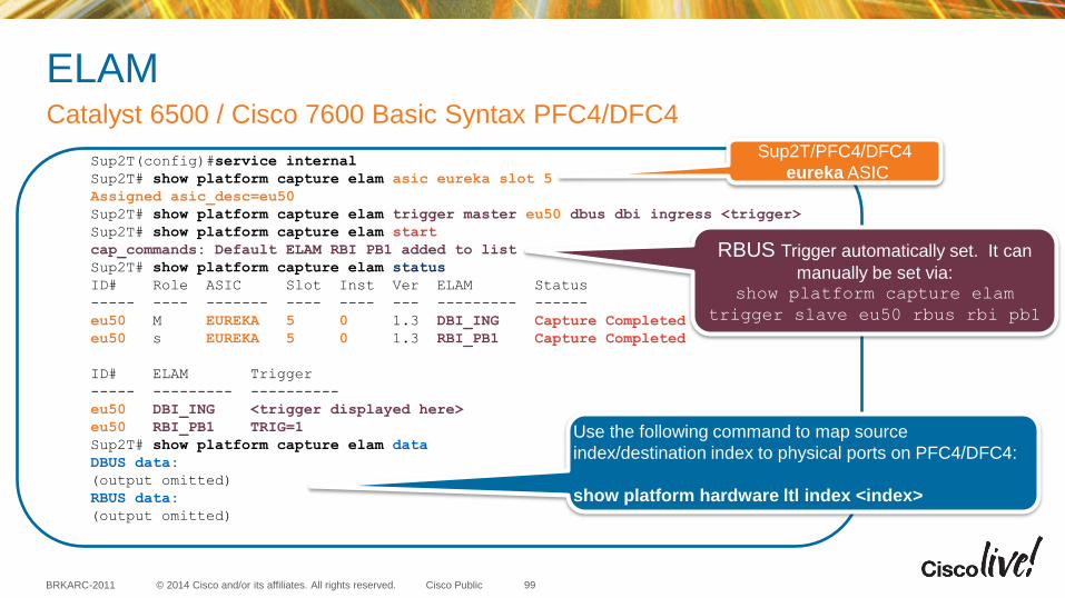
© 2014 Cisco and/or its affiliates. All rights reserved. BRKARC-2011 Cisco Public
ELAM Catalyst 6500 / Cisco 7600 Basic Syntax PFC4/DFC4
99
Sup2T(config)#service internal
Sup2T# show platform capture elam asic eureka slot 5
Assigned asic_desc=eu50
Sup2T# show platform capture elam trigger master eu50 dbus dbi ingress <trigger>
Sup2T# show platform capture elam start
cap_commands: Default ELAM RBI PB1 added to list
Sup2T# show platform capture elam status
ID# Role ASIC Slot Inst Ver ELAM Status
----- ---- ------- ---- ---- --- --------- ------
eu50 M EUREKA 5 0 1.3 DBI_ING Capture Completed
eu50 s EUREKA 5 0 1.3 RBI_PB1 Capture Completed
ID# ELAM Trigger
----- --------- ----------
eu50 DBI_ING <trigger displayed here>
eu50 RBI_PB1 TRIG=1
Sup2T# show platform capture elam data
DBUS data:
(output omitted)
RBUS data:
(output omitted)
RBUS Trigger automatically set. It can
manually be set via: show platform capture elam
trigger slave eu50 rbus rbi pb1
Sup2T/PFC4/DFC4
eureka ASIC
Use the following command to map source
index/destination index to physical ports on PFC4/DFC4:
show platform hardware ltl index <index>
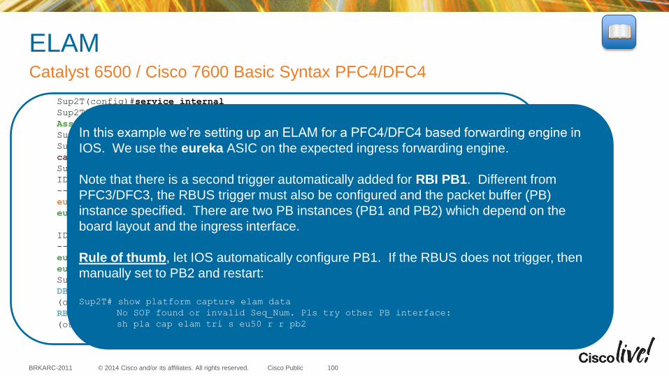
© 2014 Cisco and/or its affiliates. All rights reserved. BRKARC-2011 Cisco Public
ELAM Catalyst 6500 / Cisco 7600 Basic Syntax PFC4/DFC4
100
Sup2T(config)#service internal
Sup2T# show platform capture elam asic eureka slot 5
Assigned asic_desc=eu50
Sup2T# show platform capture elam trigger master eu50 dbus dbi ingress <trigger>
Sup2T# show platform capture elam start
cap_commands: Default ELAM RBI PB1 added to list
Sup2T# show platform capture elam status
ID# Role ASIC Slot Inst Ver ELAM Status
----- ---- ------- ---- ---- --- --------- ------
eu50 M EUREKA 5 0 1.3 DBI_ING Capture Completed
eu50 s EUREKA 5 0 1.3 RBI_PB1 Capture Completed
ID# ELAM Trigger
----- --------- ----------
eu50 DBI_ING <trigger displayed here>
eu50 RBI_PB1 TRIG=1
Sup2T# show platform capture elam data
DBUS data:
(output omitted)
RBUS data:
(output omitted)
In this example we’re setting up an ELAM for a PFC4/DFC4 based forwarding engine in
IOS. We use the eureka ASIC on the expected ingress forwarding engine.
Note that there is a second trigger automatically added for RBI PB1. Different from
PFC3/DFC3, the RBUS trigger must also be configured and the packet buffer (PB)
instance specified. There are two PB instances (PB1 and PB2) which depend on the
board layout and the ingress interface.
Rule of thumb, let IOS automatically configure PB1. If the RBUS does not trigger, then
manually set to PB2 and restart:
Sup2T# show platform capture elam data
No SOP found or invalid Seq_Num. Pls try other PB interface:
sh pla cap elam tri s eu50 r r pb2
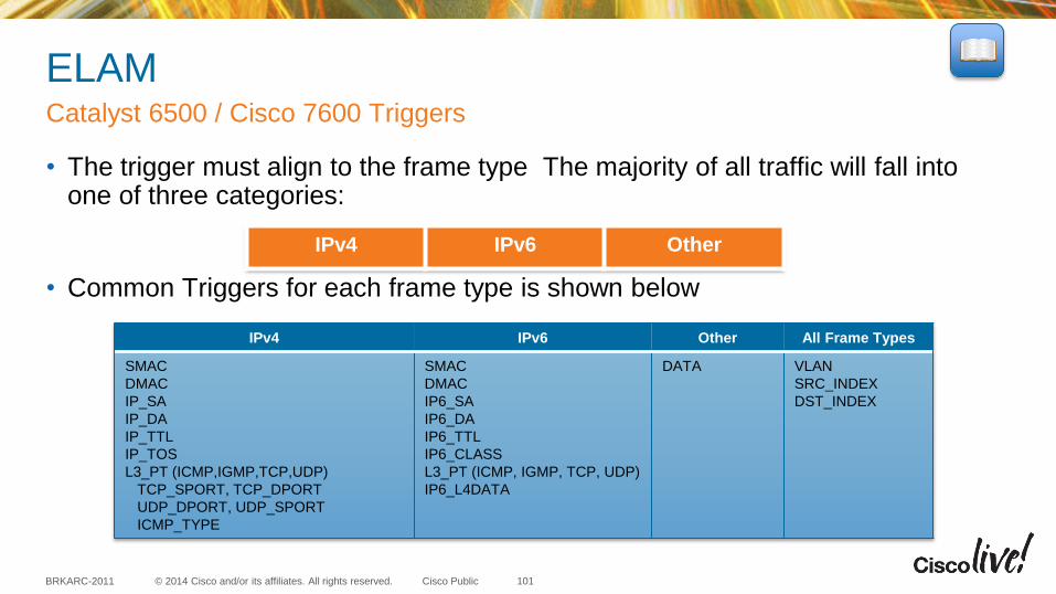
© 2014 Cisco and/or its affiliates. All rights reserved. BRKARC-2011 Cisco Public
ELAM
• The trigger must align to the frame type The majority of all traffic will fall into one of three categories:
• Common Triggers for each frame type is shown below
Catalyst 6500 / Cisco 7600 Triggers
101
IPv4 IPv6 Other All Frame Types
SMAC
DMAC
IP_SA
IP_DA
IP_TTL
IP_TOS
L3_PT (ICMP,IGMP,TCP,UDP)
TCP_SPORT, TCP_DPORT
UDP_DPORT, UDP_SPORT
ICMP_TYPE
SMAC
DMAC
IP6_SA
IP6_DA
IP6_TTL
IP6_CLASS
L3_PT (ICMP, IGMP, TCP, UDP)
IP6_L4DATA
DATA VLAN
SRC_INDEX
DST_INDEX
IPv4 IPv6 Other
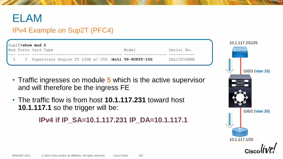
© 2014 Cisco and/or its affiliates. All rights reserved. BRKARC-2011 Cisco Public
ELAM
• Traffic ingresses on module 5 which is the active supervisor and will therefore be the ingress FE
• The traffic flow is from host 10.1.117.231 toward host 10.1.117.1 so the trigger will be:
IPv4 if IP_SA=10.1.117.231 IP_DA=10.1.117.1
IPv4 Example on Sup2T (PFC4)
102
Gi5/3 (vlan 10)
Gi5/2 (vlan 20)
10.1.117.1/25
10.1.117.231/25 Sup2T#show mod 5
Mod Ports Card Type Model Serial No.
--- ----- -------------------------------------- ------------------ -----------
5 5 Supervisor Engine 2T 10GE w/ CTS (Acti VS-SUP2T-10G SAL15056BKR
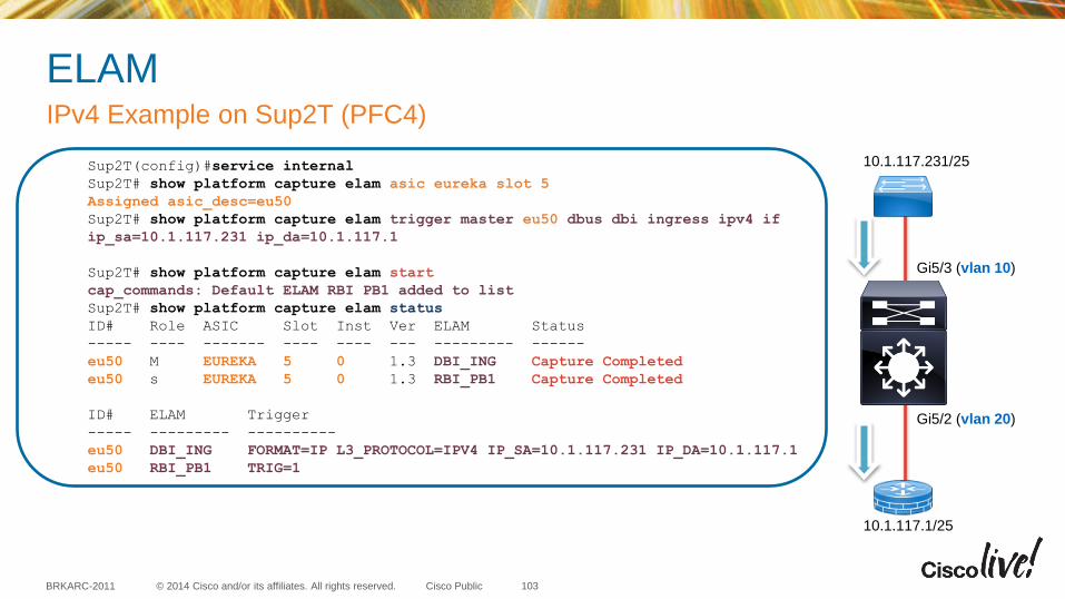
© 2014 Cisco and/or its affiliates. All rights reserved. BRKARC-2011 Cisco Public
ELAM IPv4 Example on Sup2T (PFC4)
103
Gi5/3 (vlan 10)
Gi5/2 (vlan 20)
10.1.117.1/25
10.1.117.231/25 Sup2T(config)#service internal
Sup2T# show platform capture elam asic eureka slot 5
Assigned asic_desc=eu50
Sup2T# show platform capture elam trigger master eu50 dbus dbi ingress ipv4 if
ip_sa=10.1.117.231 ip_da=10.1.117.1
Sup2T# show platform capture elam start
cap_commands: Default ELAM RBI PB1 added to list
Sup2T# show platform capture elam status
ID# Role ASIC Slot Inst Ver ELAM Status
----- ---- ------- ---- ---- --- --------- ------
eu50 M EUREKA 5 0 1.3 DBI_ING Capture Completed
eu50 s EUREKA 5 0 1.3 RBI_PB1 Capture Completed
ID# ELAM Trigger
----- --------- ----------
eu50 DBI_ING FORMAT=IP L3_PROTOCOL=IPV4 IP_SA=10.1.117.231 IP_DA=10.1.117.1
eu50 RBI_PB1 TRIG=1
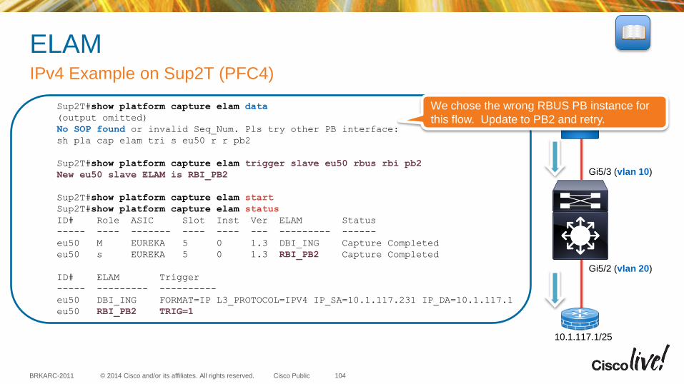
© 2014 Cisco and/or its affiliates. All rights reserved. BRKARC-2011 Cisco Public
ELAM IPv4 Example on Sup2T (PFC4)
104
Gi5/3 (vlan 10)
Gi5/2 (vlan 20)
10.1.117.1/25
10.1.117.231/25 Sup2T#show platform capture elam data
(output omitted)
No SOP found or invalid Seq_Num. Pls try other PB interface:
sh pla cap elam tri s eu50 r r pb2
Sup2T#show platform capture elam trigger slave eu50 rbus rbi pb2
New eu50 slave ELAM is RBI_PB2
Sup2T#show platform capture elam start
Sup2T#show platform capture elam status
ID# Role ASIC Slot Inst Ver ELAM Status
----- ---- ------- ---- ---- --- --------- ------
eu50 M EUREKA 5 0 1.3 DBI_ING Capture Completed
eu50 s EUREKA 5 0 1.3 RBI_PB2 Capture Completed
ID# ELAM Trigger
----- --------- ----------
eu50 DBI_ING FORMAT=IP L3_PROTOCOL=IPV4 IP_SA=10.1.117.231 IP_DA=10.1.117.1
eu50 RBI_PB2 TRIG=1
We chose the wrong RBUS PB instance for
this flow. Update to PB2 and retry.
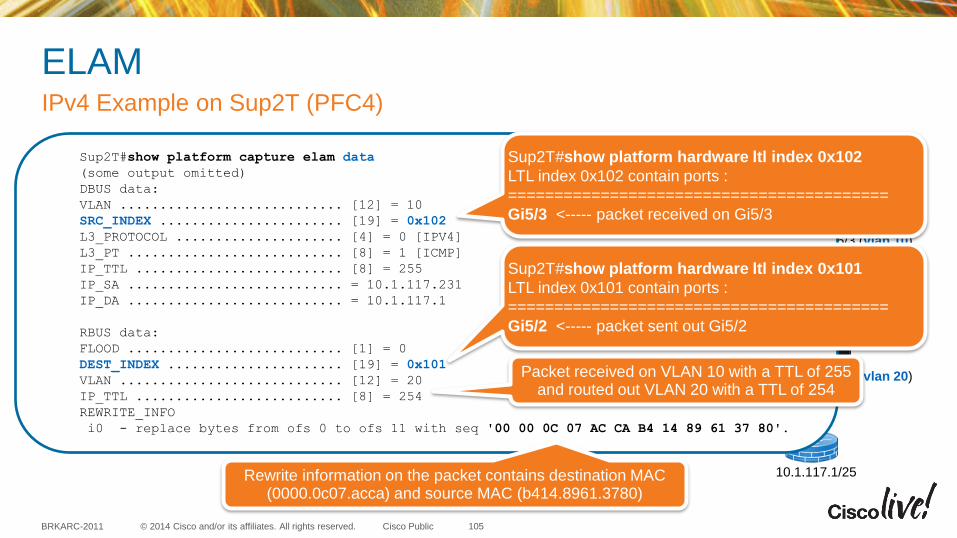
© 2014 Cisco and/or its affiliates. All rights reserved. BRKARC-2011 Cisco Public
ELAM IPv4 Example on Sup2T (PFC4)
105
Gi5/3 (vlan 10)
Gi5/2 (vlan 20)
10.1.117.1/25
10.1.117.231/25 Sup2T#show platform capture elam data
(some output omitted)
DBUS data:
VLAN ............................ [12] = 10
SRC_INDEX ....................... [19] = 0x102
L3_PROTOCOL ..................... [4] = 0 [IPV4]
L3_PT ........................... [8] = 1 [ICMP]
IP_TTL .......................... [8] = 255
IP_SA ........................... = 10.1.117.231
IP_DA ........................... = 10.1.117.1
RBUS data:
FLOOD ........................... [1] = 0
DEST_INDEX ...................... [19] = 0x101
VLAN ............................ [12] = 20
IP_TTL .......................... [8] = 254
REWRITE_INFO
i0 - replace bytes from ofs 0 to ofs 11 with seq '00 00 0C 07 AC CA B4 14 89 61 37 80'.
Sup2T#show platform hardware ltl index 0x102
LTL index 0x102 contain ports :
=========================================
Gi5/3 <----- packet received on Gi5/3
Sup2T#show platform hardware ltl index 0x101
LTL index 0x101 contain ports :
=========================================
Gi5/2 <----- packet sent out Gi5/2
Packet received on VLAN 10 with a TTL of 255 and routed out VLAN 20 with a TTL of 254
Rewrite information on the packet contains destination MAC (0000.0c07.acca) and source MAC (b414.8961.3780)
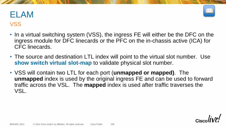
© 2014 Cisco and/or its affiliates. All rights reserved. BRKARC-2011 Cisco Public
ELAM
• In a virtual switching system (VSS), the ingress FE will either be the DFC on the ingress module for DFC linecards or the PFC on the in-chassis active (ICA) for CFC linecards.
• The source and destination LTL index will point to the virtual slot number. Use show switch virtual slot-map to validate physical slot number.
• VSS will contain two LTL for each port (unmapped or mapped). The unmapped index is used by the original ingress FE and can be used to forward traffic across the VSL. The mapped index is used after traffic traverses the VSL.
VSS
106
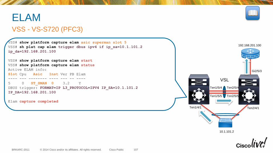
© 2014 Cisco and/or its affiliates. All rights reserved. BRKARC-2011 Cisco Public
ELAM VSS - VS-S720 (PFC3)
107
VSL
Ten1/5/4
Ten1/5/5
Ten2/5/4
Ten2/5/5
Gi2/5/3
Ten2/4/1 Ten1/4/1
10.1.101.2
192.168.201.100 VSS# show platform capture elam asic superman slot 5
VSS# sh plat cap elam trigger dbus ipv4 if ip_sa=10.1.101.2
ip_da=192.168.201.100
VSS# show platform capture elam start
VSS# show platform capture elam status
Active ELAM info:
Slot Cpu Asic Inst Ver PB Elam
---- --- -------- ---- --- -- ----
5 0 ST_SMAN 0 3.2 Y
DBUS trigger: FORMAT=IP L3_PROTOCOL=IPV4 IP_SA=10.1.101.2
IP_DA=192.168.201.100
Elam capture completed
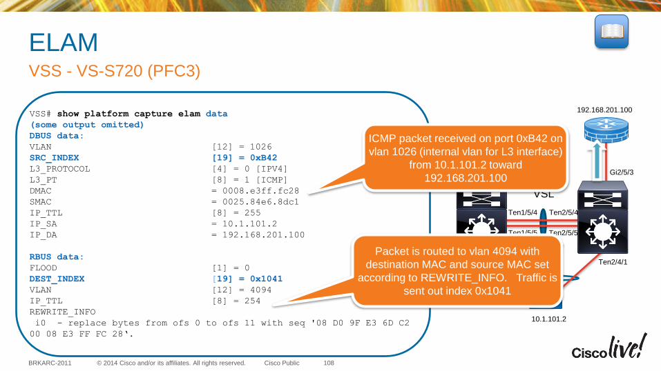
© 2014 Cisco and/or its affiliates. All rights reserved. BRKARC-2011 Cisco Public
ELAM VSS - VS-S720 (PFC3)
108
VSL
Ten1/5/4
Ten1/5/5
Ten2/5/4
Ten2/5/5
Gi2/5/3
Ten2/4/1 Ten1/4/1
10.1.101.2
192.168.201.100 VSS# show platform capture elam data
(some output omitted)
DBUS data:
VLAN [12] = 1026
SRC_INDEX [19] = 0xB42
L3_PROTOCOL [4] = 0 [IPV4]
L3_PT [8] = 1 [ICMP]
DMAC = 0008.e3ff.fc28
SMAC = 0025.84e6.8dc1
IP_TTL [8] = 255
IP_SA = 10.1.101.2
IP_DA = 192.168.201.100
RBUS data:
FLOOD [1] = 0
DEST_INDEX [19] = 0x1041
VLAN [12] = 4094
IP_TTL [8] = 254
REWRITE_INFO
i0 - replace bytes from ofs 0 to ofs 11 with seq '08 D0 9F E3 6D C2
00 08 E3 FF FC 28‘.
ICMP packet received on port 0xB42 on
vlan 1026 (internal vlan for L3 interface)
from 10.1.101.2 toward
192.168.201.100
Packet is routed to vlan 4094 with
destination MAC and source MAC set
according to REWRITE_INFO. Traffic is
sent out index 0x1041
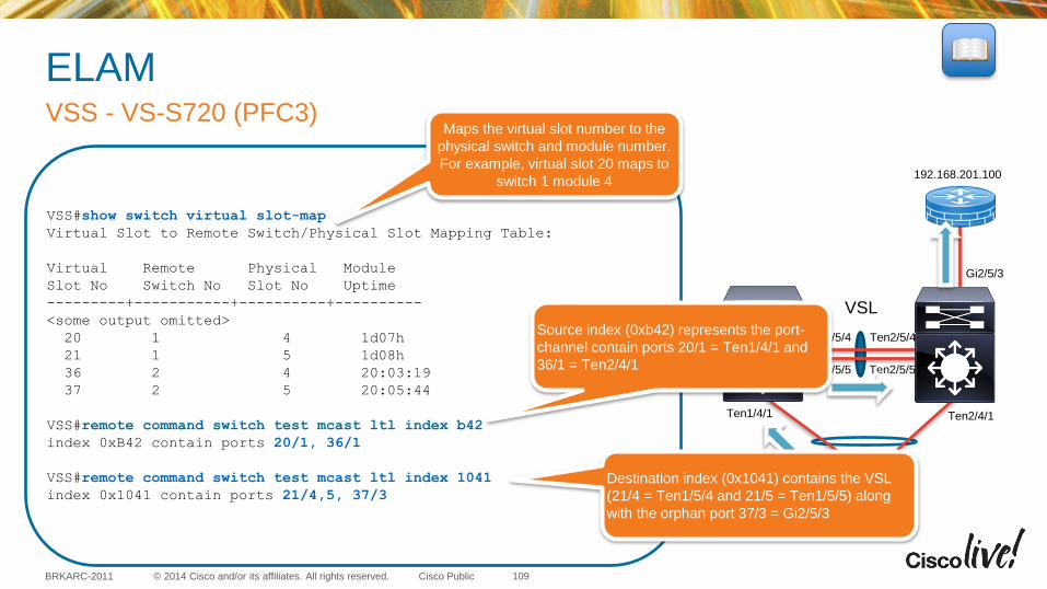
© 2014 Cisco and/or its affiliates. All rights reserved. BRKARC-2011 Cisco Public
ELAM VSS - VS-S720 (PFC3)
109
VSL
Ten1/5/4
Ten1/5/5
Ten2/5/4
Ten2/5/5
Gi2/5/3
Ten2/4/1 Ten1/4/1
10.1.101.2
192.168.201.100
VSS#show switch virtual slot-map
Virtual Slot to Remote Switch/Physical Slot Mapping Table:
Virtual Remote Physical Module
Slot No Switch No Slot No Uptime
---------+-----------+----------+----------
<some output omitted>
20 1 4 1d07h
21 1 5 1d08h
36 2 4 20:03:19
37 2 5 20:05:44
VSS#remote command switch test mcast ltl index b42
index 0xB42 contain ports 20/1, 36/1
VSS#remote command switch test mcast ltl index 1041
index 0x1041 contain ports 21/4,5, 37/3
Source index (0xb42) represents the port-
channel contain ports 20/1 = Ten1/4/1 and
36/1 = Ten2/4/1
Maps the virtual slot number to the
physical switch and module number.
For example, virtual slot 20 maps to
switch 1 module 4
Destination index (0x1041) contains the VSL
(21/4 = Ten1/5/4 and 21/5 = Ten1/5/5) along
with the orphan port 37/3 = Gi2/5/3

© 2014 Cisco and/or its affiliates. All rights reserved. BRKARC-2011 Cisco Public
ELAM VSS - VS-S720 (PFC3)
110
VSL
Ten1/5/4
Ten1/5/5
Ten2/5/4
Ten2/5/5
Gi2/5/3
Ten2/4/1 Ten1/4/1
10.1.101.2
192.168.201.100 VSS#remote login switch-id 2 module 5
VSS-sdby-sp# show platform capture elam asic superman slot 5
VSS-sdby-sp# sh plat cap elam trigger dbus ipv4 if ip_sa=10.1.101.2
ip_da=192.168.201.100
VSS-sdby-sp# show platform capture elam start
VSS-sdby-sp# show platform capture elam status
Active ELAM info:
Slot Cpu Asic Inst Ver PB Elam
---- --- -------- ---- --- -- ----
5 0 ST_SMAN 0 3.2 Y
DBUS trigger: FORMAT=IP L3_PROTOCOL=IPV4 IP_SA=10.1.101.2
IP_DA=192.168.201.100
Elam capture completed
VSS-sdby-sp#show platform capture elam data | i VLAN|INDEX|BUS
DBUS data:
VLAN [12] = 4094
SRC_INDEX [19] = 0xB42
RBUS data:
DEST_INDEX [19] = 0x2841
VLAN [12] = 4094
First capture verified that traffic was received
on Switch 1 with destination containing VSL.
This traffic should be switched across the
VSL so we can perform another capture on
Switch2 to verify the frame was received and
decision still points to G2/5/3
VSS#remote command switch test mcast ltl index 2841
index 0x2841 contain ports 37/3
Mapped Index contains only 37/3 = Gi2/5/3, so this frame
will be switched on VLAN 4094 from the VSL link out
G2/5/3.
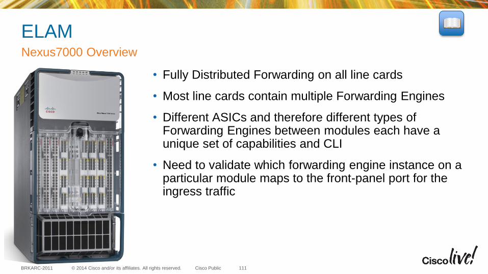
© 2014 Cisco and/or its affiliates. All rights reserved. BRKARC-2011 Cisco Public
ELAM
• Fully Distributed Forwarding on all line cards
• Most line cards contain multiple Forwarding Engines
• Different ASICs and therefore different types of Forwarding Engines between modules each have a unique set of capabilities and CLI
• Need to validate which forwarding engine instance on a particular module maps to the front-panel port for the ingress traffic
Nexus7000 Overview
111
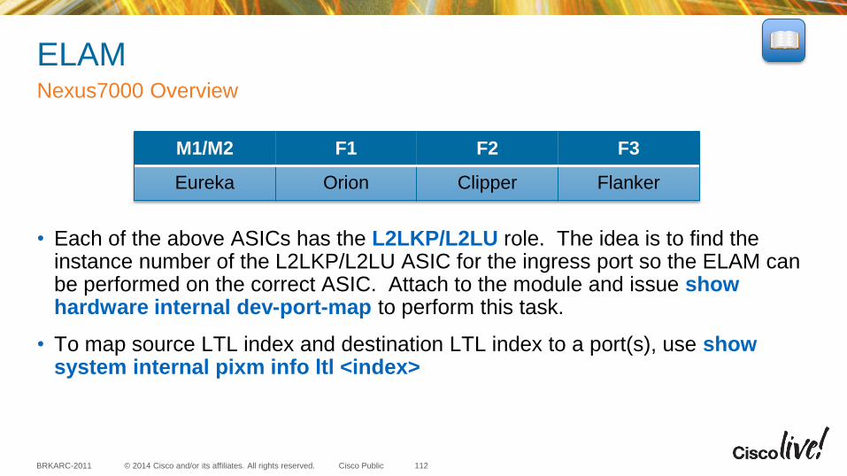
© 2014 Cisco and/or its affiliates. All rights reserved. BRKARC-2011 Cisco Public
ELAM
• Each of the above ASICs has the L2LKP/L2LU role. The idea is to find the instance number of the L2LKP/L2LU ASIC for the ingress port so the ELAM can be performed on the correct ASIC. Attach to the module and issue show hardware internal dev-port-map to perform this task.
• To map source LTL index and destination LTL index to a port(s), use show system internal pixm info ltl <index>
Nexus7000 Overview
112
M1/M2 F1 F2 F3
Eureka Orion Clipper Flanker
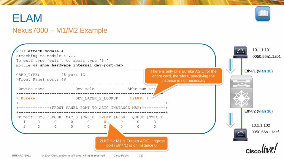
© 2014 Cisco and/or its affiliates. All rights reserved. BRKARC-2011 Cisco Public
ELAM Nexus7000 – M1/M2 Example
113
Eth4/1 (vlan 10)
Eth4/2 (vlan 10)
N7k# attach module 4
Attaching to module 4 ...
To exit type 'exit', to abort type '$.'
module-4# show hardware internal dev-port-map
--------------------------------------------------------------
CARD_TYPE: 48 port 1G
>Front Panel ports:48
--------------------------------------------------------------
Device name Dev role Abbr num_inst:
--------------------------------------------------------------
> Eureka DEV_LAYER_2_LOOKUP L2LKP 1
+--------------------------------------------------------------+
+-----------+++FRONT PANEL PORT TO ASIC INSTANCE MAP+++--------+
+--------------------------------------------------------------+
FP port|PHYS |SECUR |MAC_0 |RWR_0 |L2LKP |L3LKP |QUEUE |SWICHF
1 0 0 0 0 0 0 0 0
2 0 0 0 0 0 0 0 0
L2LKP for M1 is Eureka ASIC. Ingress port (Eth4/1) is on instance 0
10.1.1.101
0050.56a1.1a01
10.1.1.102
0050.56a1.1aef
There is only one Eureka ASIC for the
entire card, therefore, specifying the instance is not necessary
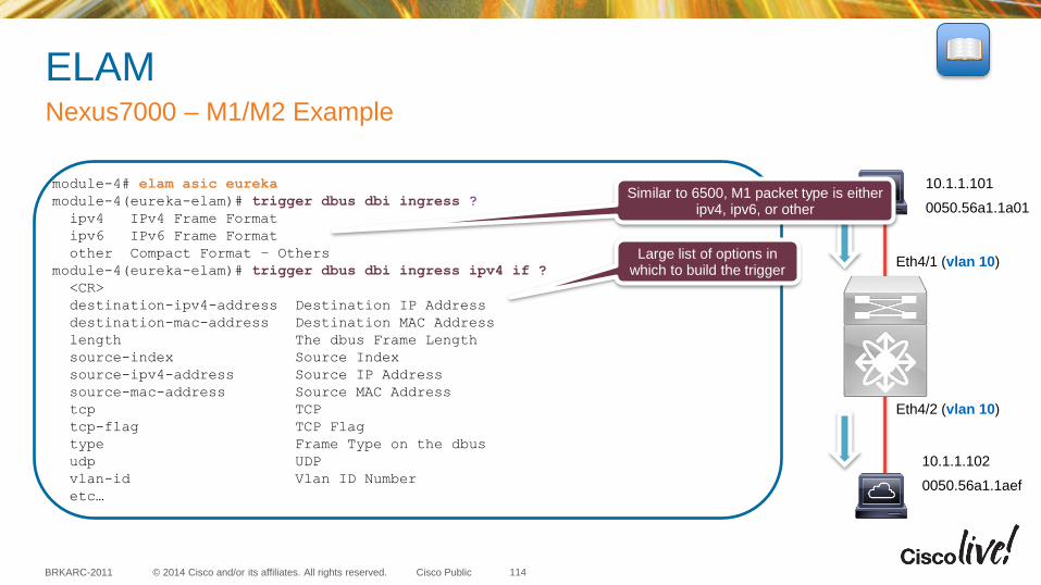
© 2014 Cisco and/or its affiliates. All rights reserved. BRKARC-2011 Cisco Public
ELAM Nexus7000 – M1/M2 Example
114
Eth4/1 (vlan 10)
Eth4/2 (vlan 10)
module-4# elam asic eureka
module-4(eureka-elam)# trigger dbus dbi ingress ?
ipv4 IPv4 Frame Format
ipv6 IPv6 Frame Format
other Compact Format – Others
module-4(eureka-elam)# trigger dbus dbi ingress ipv4 if ?
<CR>
destination-ipv4-address Destination IP Address
destination-mac-address Destination MAC Address
length The dbus Frame Length
source-index Source Index
source-ipv4-address Source IP Address
source-mac-address Source MAC Address
tcp TCP
tcp-flag TCP Flag
type Frame Type on the dbus
udp UDP
vlan-id Vlan ID Number
etc…
Similar to 6500, M1 packet type is either ipv4, ipv6, or other
Large list of options in which to build the trigger
10.1.1.101
0050.56a1.1a01
10.1.1.102
0050.56a1.1aef
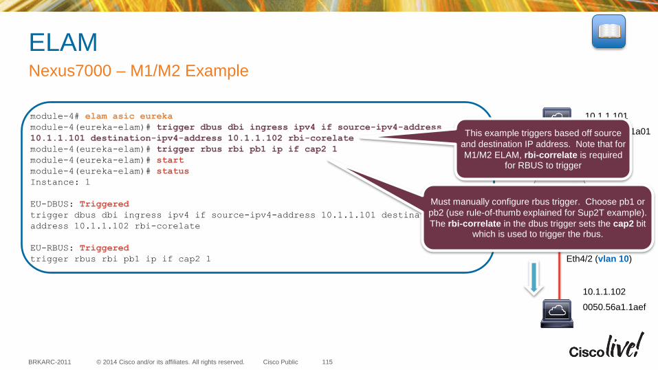
© 2014 Cisco and/or its affiliates. All rights reserved. BRKARC-2011 Cisco Public
10.1.1.101
0050.56a1.1a01
ELAM Nexus7000 – M1/M2 Example
115
Eth4/1 (vlan 10)
Eth4/2 (vlan 10)
module-4# elam asic eureka
module-4(eureka-elam)# trigger dbus dbi ingress ipv4 if source-ipv4-address
10.1.1.101 destination-ipv4-address 10.1.1.102 rbi-corelate
module-4(eureka-elam)# trigger rbus rbi pb1 ip if cap2 1
module-4(eureka-elam)# start
module-4(eureka-elam)# status
Instance: 1
EU-DBUS: Triggered
trigger dbus dbi ingress ipv4 if source-ipv4-address 10.1.1.101 destination-ipv4-
address 10.1.1.102 rbi-corelate
EU-RBUS: Triggered
trigger rbus rbi pb1 ip if cap2 1
This example triggers based off source
and destination IP address. Note that for
M1/M2 ELAM, rbi-correlate is required for RBUS to trigger
Must manually configure rbus trigger. Choose pb1 or
pb2 (use rule-of-thumb explained for Sup2T example).
The rbi-correlate in the dbus trigger sets the cap2 bit which is used to trigger the rbus.
10.1.1.102
0050.56a1.1aef
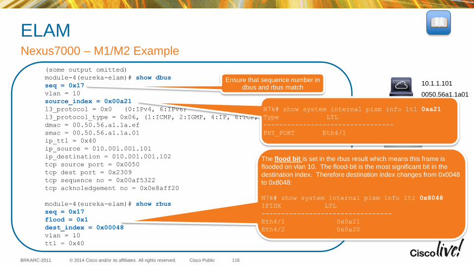
© 2014 Cisco and/or its affiliates. All rights reserved. BRKARC-2011 Cisco Public
10.1.1.102
0050.56a1.1aef
ELAM Nexus7000 – M1/M2 Example
116
Eth4/1 (vlan 10)
Eth4/2 (vlan 10)
(some output omitted)
module-4(eureka-elam)# show dbus
seq = 0x17
vlan = 10
source_index = 0x00a21
l3_protocol = 0x0 (0:IPv4, 6:IPv6)
l3_protocol_type = 0x06, (1:ICMP, 2:IGMP, 4:IP, 6:TCP, 17:UDP)
dmac = 00.50.56.a1.1a.ef
smac = 00.50.56.a1.1a.01
ip_ttl = 0x40
ip_source = 010.001.001.101
ip_destination = 010.001.001.102
tcp source port = 0x0050
tcp dest port = 0x2309
tcp sequence no = 0x00af5322
tcp acknoledgement no = 0x0e8aff20
module-4(eureka-elam)# show rbus
seq = 0x17
flood = 0x1
dest_index = 0x00048
vlan = 10
ttl = 0x40
Ensure that sequence number in dbus and rbus match
N7k# show system internal pixm info ltl 0xa21
Type LTL
---------------------------------
PHY_PORT Eth4/1
The flood bit is set in the rbus result which means this frame is
flooded on vlan 10. The flood-bit is the most significant bit in the
destination index. Therefore destination index changes from 0x0048
to 0x8048:
N7k# show system internal pixm info ltl 0x8048
IFIDX LTL
---------------------------------
Eth4/1 0x0a21
Eth4/2 0x0a20
10.1.1.101
0050.56a1.1a01

© 2014 Cisco and/or its affiliates. All rights reserved. BRKARC-2011 Cisco Public
ELAM Nexus7000 – F1 Example
117
Eth3/18 (vlan 10)
Eth3/26 (vlan 10)
10.1.1.101
0050.56a1.1a01
10.1.1.102
0050.56a1.1aef
N7k# attach module 3
Attaching to module 3 ...
To exit type 'exit', to abort type '$.'
module-3# show hardware internal dev-port-map
--------------------------------------------------------------
CARD_TYPE: DCE 32 port 10G
>Front Panel ports:32
--------------------------------------------------------------
Device name Dev role Abbr num_inst:
--------------------------------------------------------------
> Orion Fwding Driver DEV_LAYER_2_LOOKUP L2LKP 16
+--------------------------------------------------------------+
+-----------+++FRONT PANEL PORT TO ASIC INSTANCE MAP+++--------+
+--------------------------------------------------------------+
FP port | PHYS | MAC_0 | L2LKP | QUEUE |SWICHF
...
18 8 8 8 8 1
...
26 12 12 12 12 1
16 different FE on F1 module
Ingress port 18 is on FE 8
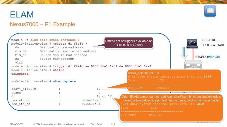
© 2014 Cisco and/or its affiliates. All rights reserved. BRKARC-2011 Cisco Public
ELAM Nexus7000 – F1 Example
118
Eth3/18 (vlan 10)
Eth3/26 (vlan 10)
10.1.1.101
0050.56a1.1a01
10.1.1.102
0050.56a1.1aef
module-3# elam asic orion instance 8
module-3(orion-elam)# trigger di field ?
da Destination mac-address
mim_da Destination mac-in-mac-address
mim_sa Source mac-in-mac-address
sa Source mac-address
vlan
module-3(orion-elam)# trigger di field sa 0050.56a1.1a01 da 0050.56a1.1aef
module-3(orion-elam)# status
Triggered
module-3(orion-elam)# show capture
...
dc3v4_si[11:0] : 17
vlanx : a
di : 1e or 1f
res_eth_da : 5056a11aef
res_eth_sa : 5056a11a01
Limited set of triggers available on
F1 since it is L2 only
Orion ELAM parser cannot read least significant bit in destination index,
therefore two values are printed. In this case, 0x1f is the correct index N7k# show system internal pixm info ltl 0x1f
Type LTL
---------------------------------
PHY_PORT Eth3/26
dc3v4_si is source LTL. N7k# show system internal pixm info ltl 0x17
Type LTL
---------------------------------
PHY_PORT Eth3/18
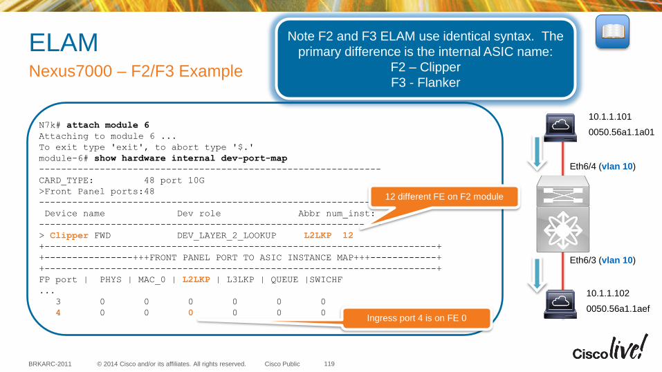
© 2014 Cisco and/or its affiliates. All rights reserved. BRKARC-2011 Cisco Public
ELAM Nexus7000 – F2/F3 Example
Eth6/4 (vlan 10)
Eth6/3 (vlan 10)
10.1.1.101
0050.56a1.1a01
10.1.1.102
0050.56a1.1aef
N7k# attach module 6
Attaching to module 6 ...
To exit type 'exit', to abort type '$.'
module-6# show hardware internal dev-port-map
--------------------------------------------------------------
CARD_TYPE: 48 port 10G
>Front Panel ports:48
--------------------------------------------------------------
Device name Dev role Abbr num_inst:
--------------------------------------------------------------
> Clipper FWD DEV_LAYER_2_LOOKUP L2LKP 12
+-----------------------------------------------------------------------+
+----------------+++FRONT PANEL PORT TO ASIC INSTANCE MAP+++------------+
+-----------------------------------------------------------------------+
FP port | PHYS | MAC_0 | L2LKP | L3LKP | QUEUE |SWICHF
...
3 0 0 0 0 0 0
4 0 0 0 0 0 0
12 different FE on F2 module
Ingress port 4 is on FE 0
Note F2 and F3 ELAM use identical syntax. The
primary difference is the internal ASIC name:
F2 – Clipper
F3 - Flanker
119
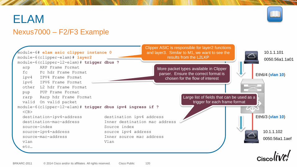
© 2014 Cisco and/or its affiliates. All rights reserved. BRKARC-2011 Cisco Public
ELAM Nexus7000 – F2/F3 Example
Eth6/4 (vlan 10)
Eth6/3 (vlan 10)
10.1.1.101
0050.56a1.1a01
10.1.1.102
0050.56a1.1aef
module-6# elam asic clipper instance 0
module-6(clipper-elam)# layer2
module-6(clipper-l2-elam)# trigger dbus ?
arp ARP Frame Format
fc Fc hdr Frame Format
ipv4 IPV4 Frame Format
ipv6 IPV6 Frame Format
other L2 hdr Frame Format
pup PUP Frame Format
rarp Rarp hdr Frame Format
valid On valid packet
module-6(clipper-l2-elam)# trigger dbus ipv4 ingress if ?
<CR>
destination-ipv4-address destination ipv4 address
destination-mac-address Inner destination mac address
source-index Source index
source-ipv4-address source ipv4 address
source-mac-address Inner source mac address
vlan Vlan
etc…
Clipper ASIC is responsible for layer2 functions
and layer3. Similar to M1, we want to see the results from the L2LKP
More packet types available in Clipper
parser. Ensure the correct format is chosen for the flow of interest
Large list of fields that can be used as a trigger for each frame format
120
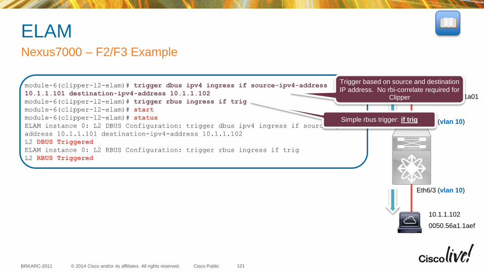
© 2014 Cisco and/or its affiliates. All rights reserved. BRKARC-2011 Cisco Public
ELAM Nexus7000 – F2/F3 Example
Eth6/4 (vlan 10)
Eth6/3 (vlan 10)
10.1.1.101
0050.56a1.1a01
10.1.1.102
0050.56a1.1aef
module-6(clipper-l2-elam)# trigger dbus ipv4 ingress if source-ipv4-address
10.1.1.101 destination-ipv4-address 10.1.1.102
module-6(clipper-l2-elam)# trigger rbus ingress if trig
module-6(clipper-l2-elam)# start
module-6(clipper-l2-elam)# status
ELAM instance 0: L2 DBUS Configuration: trigger dbus ipv4 ingress if source-ipv4-
address 10.1.1.101 destination-ipv4-address 10.1.1.102
L2 DBUS Triggered
ELAM instance 0: L2 RBUS Configuration: trigger rbus ingress if trig
L2 RBUS Triggered
Trigger based on source and destination
IP address. No rbi-correlate required for Clipper
Simple rbus trigger: if trig
121
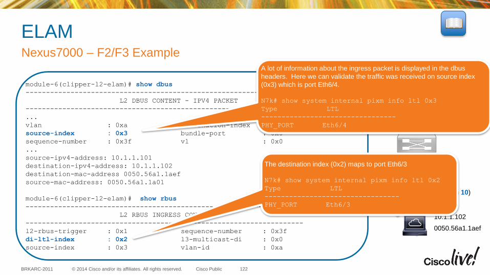
© 2014 Cisco and/or its affiliates. All rights reserved. BRKARC-2011 Cisco Public
ELAM Nexus7000 – F2/F3 Example
Eth6/4 (vlan 10)
Eth6/3 (vlan 10)
10.1.1.101
0050.56a1.1a01
10.1.1.102
0050.56a1.1aef
module-6(clipper-l2-elam)# show dbus
--------------------------------------------------------------------
L2 DBUS CONTENT - IPV4 PACKET
--------------------------------------------------------------------
...
vlan : 0xa destination-index : 0x0
source-index : 0x3 bundle-port : 0x0
sequence-number : 0x3f vl : 0x0
...
source-ipv4-address: 10.1.1.101
destination-ipv4-address: 10.1.1.102
destination-mac-address 0050.56a1.1aef
source-mac-address: 0050.56a1.1a01
module-6(clipper-l2-elam)# show rbus
--------------------------------------------------------------------
L2 RBUS INGRESS CONTENT
--------------------------------------------------------------------
l2-rbus-trigger : 0x1 sequence-number : 0x3f
di-ltl-index : 0x2 l3-multicast-di : 0x0
source-index : 0x3 vlan-id : 0xa
A lot of information about the ingress packet is displayed in the dbus
headers. Here we can validate the traffic was received on source index
(0x3) which is port Eth6/4.
N7k# show system internal pixm info ltl 0x3
Type LTL
---------------------------------
PHY_PORT Eth6/4
The destination index (0x2) maps to port Eth6/3
N7k# show system internal pixm info ltl 0x2
Type LTL
---------------------------------
PHY_PORT Eth6/3
122

© 2014 Cisco and/or its affiliates. All rights reserved. BRKARC-2011 Cisco Public
Agenda
• Introduction
• Capturing Packets at the Control Plane
• Capturing Packets at the Data Plane
• Tips and Tricks
• Putting it All Together
• Q&A
123
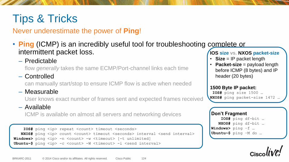
© 2014 Cisco and/or its affiliates. All rights reserved. BRKARC-2011 Cisco Public
Tips & Tricks
• Ping (ICMP) is an incredibly useful tool for troubleshooting complete or intermittent packet loss.
– Predictable flow generally takes the same ECMP/Port-channel links each time
– Controlled can manually start/stop to ensure ICMP flow is active when needed
– Measurable User knows exact number of frames sent and expected frames received
– Available ICMP is available on almost all servers and networking devices
Never underestimate the power of Ping!
124
IOS# ping <ip> repeat <count> timeout <seconds>
NXOS# ping <ip> count <count> timeout <seconds> interval <send interval>
Windows> ping <ip> -n <count> -w <timeout> [-t unlimited]
Ubuntu~$ ping <ip> -c <count> -W <timeout> -i <send interval>
IOS size vs. NXOS packet-size
• Size = IP packet length
• Packet-size = payload length
before ICMP (8 bytes) and IP
header (20 bytes)
1500 Byte IP packet: IOS# ping size 1500 …
NXOS# ping packet-size 1472 …
Don’t Fragment IOS# ping df-bit …
NXOS# ping df-bit …
Windows> ping –f …
Ubuntu~$ ping –M do …
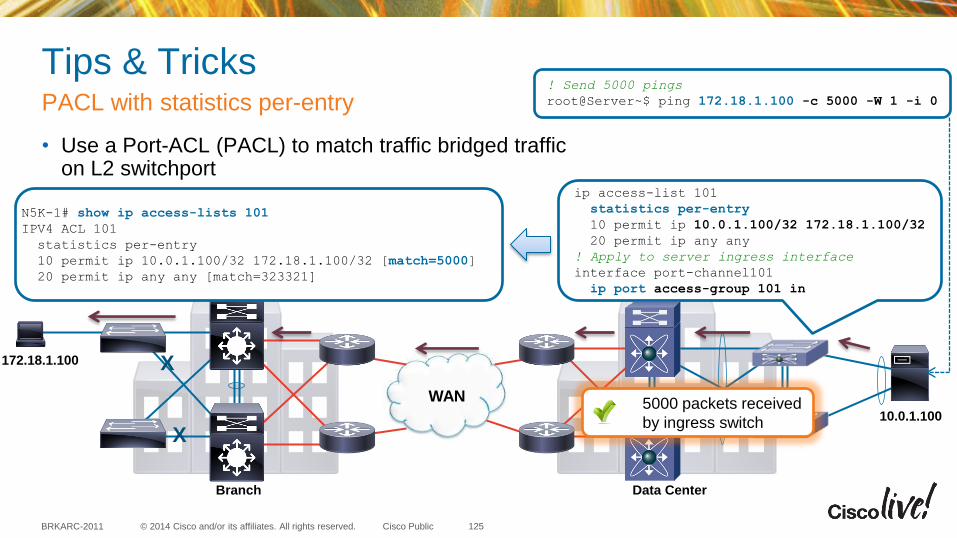
© 2014 Cisco and/or its affiliates. All rights reserved. BRKARC-2011 Cisco Public
Tips & Tricks
• Use a Port-ACL (PACL) to match traffic bridged traffic on L2 switchport
PACL with statistics per-entry
125
WAN
Data Center Branch
X
X
172.18.1.100
10.0.1.100
! Send 5000 pings
root@Server~$ ping 172.18.1.100 -c 5000 -W 1 -i 0
ip access-list 101
statistics per-entry
10 permit ip 10.0.1.100/32 172.18.1.100/32
20 permit ip any any
! Apply to server ingress interface
interface port-channel101
ip port access-group 101 in
N5K-1# show ip access-lists 101
IPV4 ACL 101
statistics per-entry
10 permit ip 10.0.1.100/32 172.18.1.100/32 [match=5000]
20 permit ip any any [match=323321]
5000 packets received
by ingress switch
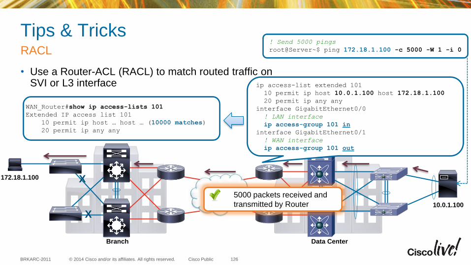
© 2014 Cisco and/or its affiliates. All rights reserved. BRKARC-2011 Cisco Public
Tips & Tricks
• Use a Router-ACL (RACL) to match routed traffic on SVI or L3 interface
RACL
126
WAN
Data Center Branch
X
X
172.18.1.100
10.0.1.100
! Send 5000 pings
root@Server~$ ping 172.18.1.100 -c 5000 -W 1 -i 0
WAN_Router#show ip access-lists 101
Extended IP access list 101
10 permit ip host … host … (10000 matches)
20 permit ip any any
5000 packets received and
transmitted by Router
ip access-list extended 101
10 permit ip host 10.0.1.100 host 172.18.1.100
20 permit ip any any
interface GigabitEthernet0/0
! LAN interface
ip access-group 101 in
interface GigabitEthernet0/1
! WAN interface
ip access-group 101 out
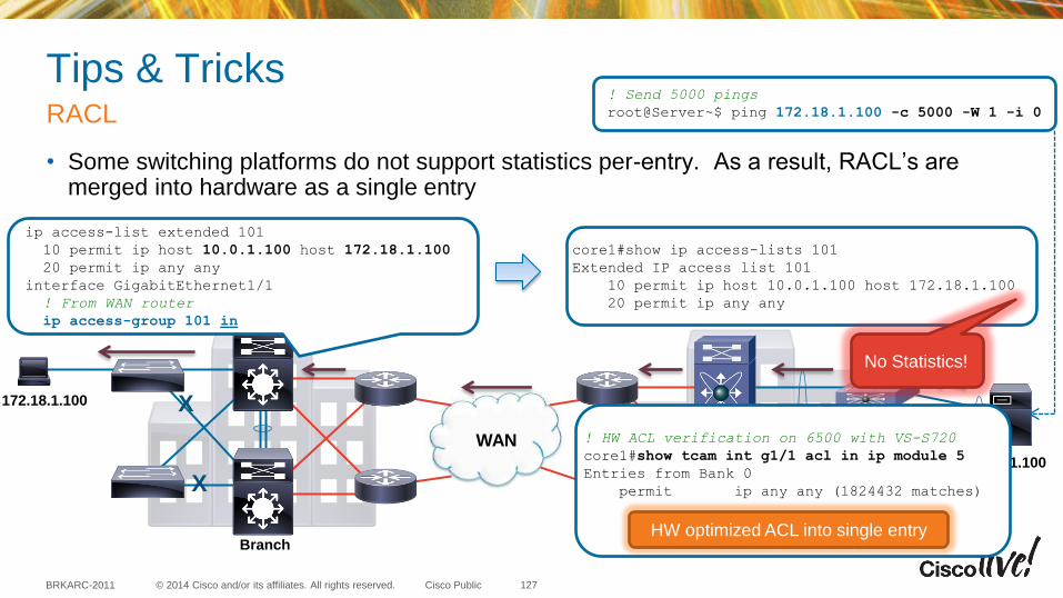
© 2014 Cisco and/or its affiliates. All rights reserved. BRKARC-2011 Cisco Public
Tips & Tricks
• Some switching platforms do not support statistics per-entry. As a result, RACL’s are merged into hardware as a single entry
RACL
127
WAN
Data Center Branch
X
X
172.18.1.100
10.0.1.100
! Send 5000 pings
root@Server~$ ping 172.18.1.100 -c 5000 -W 1 -i 0
ip access-list extended 101
10 permit ip host 10.0.1.100 host 172.18.1.100
20 permit ip any any
interface GigabitEthernet1/1
! From WAN router
ip access-group 101 in
core1#show ip access-lists 101
Extended IP access list 101
10 permit ip host 10.0.1.100 host 172.18.1.100
20 permit ip any any
! HW ACL verification on 6500 with VS-S720
core1#show tcam int g1/1 acl in ip module 5
Entries from Bank 0
permit ip any any (1824432 matches)
HW optimized ACL into single entry
No Statistics!
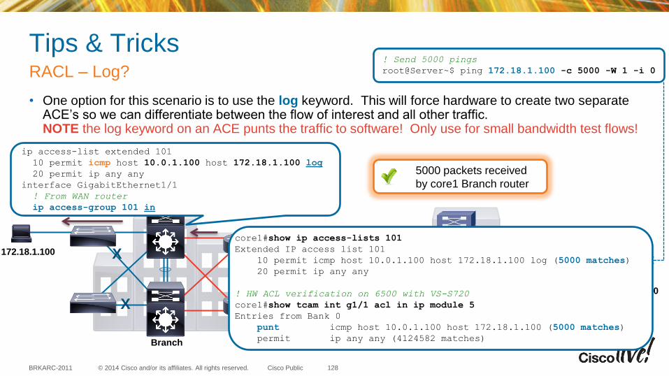
© 2014 Cisco and/or its affiliates. All rights reserved. BRKARC-2011 Cisco Public
Tips & Tricks
• One option for this scenario is to use the log keyword. This will force hardware to create two separate ACE’s so we can differentiate between the flow of interest and all other traffic. NOTE the log keyword on an ACE punts the traffic to software! Only use for small bandwidth test flows!
RACL – Log?
128
WAN
Data Center Branch
X
X
172.18.1.100
10.0.1.100
! Send 5000 pings
root@Server~$ ping 172.18.1.100 -c 5000 -W 1 -i 0
ip access-list extended 101
10 permit icmp host 10.0.1.100 host 172.18.1.100 log
20 permit ip any any
interface GigabitEthernet1/1
! From WAN router
ip access-group 101 in
5000 packets received
by core1 Branch router
core1#show ip access-lists 101
Extended IP access list 101
10 permit icmp host 10.0.1.100 host 172.18.1.100 log (5000 matches)
20 permit ip any any
! HW ACL verification on 6500 with VS-S720
core1#show tcam int g1/1 acl in ip module 5
Entries from Bank 0
punt icmp host 10.0.1.100 host 172.18.1.100 (5000 matches)
permit ip any any (4124582 matches)
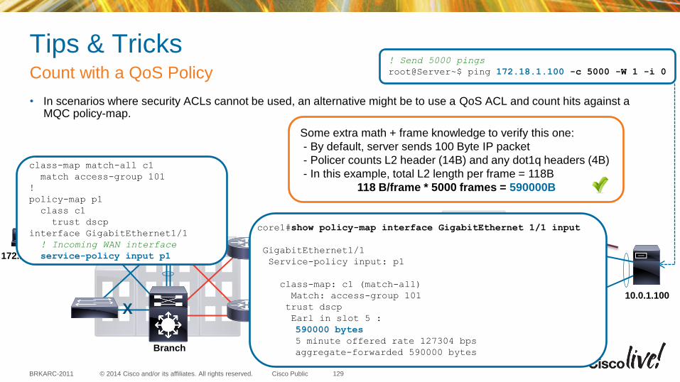
© 2014 Cisco and/or its affiliates. All rights reserved. BRKARC-2011 Cisco Public
Tips & Tricks
• In scenarios where security ACLs cannot be used, an alternative might be to use a QoS ACL and count hits against a MQC policy-map.
Count with a QoS Policy
129
WAN
Data Center Branch
X
X
172.18.1.100
10.0.1.100
! Send 5000 pings
root@Server~$ ping 172.18.1.100 -c 5000 -W 1 -i 0
Some extra math + frame knowledge to verify this one:
- By default, server sends 100 Byte IP packet
- Policer counts L2 header (14B) and any dot1q headers (4B)
- In this example, total L2 length per frame = 118B
118 B/frame * 5000 frames = 590000B
class-map match-all c1
match access-group 101
!
policy-map p1
class c1
trust dscp
interface GigabitEthernet1/1
! Incoming WAN interface
service-policy input p1
core1#show policy-map interface GigabitEthernet 1/1 input
GigabitEthernet1/1
Service-policy input: p1
class-map: c1 (match-all)
Match: access-group 101
trust dscp
Earl in slot 5 :
590000 bytes
5 minute offered rate 127304 bps
aggregate-forwarded 590000 bytes
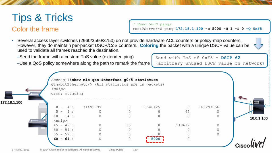
© 2014 Cisco and/or its affiliates. All rights reserved. BRKARC-2011 Cisco Public
Tips & Tricks
• Several access layer switches (2960/3560/3750) do not provide hardware ACL counters or policy-map counters. However, they do maintain per-packet DSCP/CoS counters. Coloring the packet with a unique DSCP value can be used to validate all frames reached the destination.
–Send the frame with a custom ToS value (extended ping)
–Use a QoS policy somewhere along the path to remark the frame
Color the frame
130
WAN
Data Center Branch
X
X
172.18.1.100
10.0.1.100
! Send 5000 pings
root@Server~$ ping 172.18.1.100 -c 5000 -W 1 -i 0 –Q 0xF8
Send with ToS of 0xF8 = DSCP 62
(arbitrary unused DSCP value on network)
Access-1#show mls qos interface g0/5 statistics
GigabitEthernet0/5 (All statistics are in packets)
<snip>
dscp: outgoing
-------------------------------
0 - 4 : 71492999 0 16546425 0 102297056
5 - 9 : 0 0 0 65 0
10 - 14 : 0 0 0 0 0
<snip>
45 - 49 : 0 15 0 218612 0
50 - 54 : 0 0 0 0 0
55 - 59 : 0 0 0 0 0
60 - 64 : 0 0 5000 0
© 2014 Cisco and/or its affiliates. All rights reserved. BRKARC-2011 Cisco Public
Agenda
• Introduction
• Capturing Packets at the Control Plane
• Capturing Packets at the Data Plane
• Tips and Tricks
• Putting it All Together
• Q&A
131
Putting It All Together
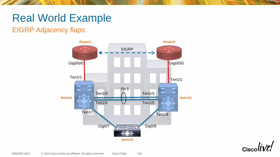
© 2014 Cisco and/or its affiliates. All rights reserved. BRKARC-2011 Cisco Public
Real World Example EIGRP Adjacency flaps
Router1 Router2
Switch1 Switch2
Switch3
Gig0/7 Gig0/8
Ten1/7 Ten1/8
Ten1/1
Gig0/0/0 Gig0/0/0
Ten1/1
Ten1/3
Ten1/5
Po 1
Ten1/3
Ten1/5
EIGRP
133
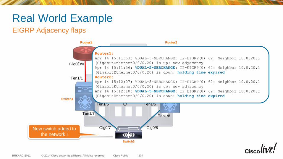
© 2014 Cisco and/or its affiliates. All rights reserved. BRKARC-2011 Cisco Public
Router1 Router2
Switch1 Switch2
Switch3
Gig0/7 Gig0/8
Ten1/7 Ten1/8
Ten1/1
Gig0/0/0 Gig0/0/0
Ten1/1
Ten1/3
Ten1/5
Po 1
Ten1/3
Ten1/5
EIGRP
Real World Example EIGRP Adjacency flaps
Switch 2
New switch added to
the network !
Router1:
Apr 14 15:11:53: %DUAL-5-NBRCHANGE: IP-EIGRP(0) 62: Neighbor 10.0.20.1
(GigabitEthernet0/0/0.20) is up: new adjacency
Apr 14 15:11:56: %DUAL-5-NBRCHANGE: IP-EIGRP(0) 62: Neighbor 10.0.20.1
(GigabitEthernet0/0/0.20) is down: holding time expired
Router2:
Apr 14 15:12:07: %DUAL-5-NBRCHANGE: IP-EIGRP(0) 62: Neighbor 10.0.20.1
(GigabitEthernet0/0/0.20) is up: new adjacency
Apr 14 15:12:10: %DUAL-5-NBRCHANGE: IP-EIGRP(0) 62: Neighbor 10.0.20.1
(GigabitEthernet0/0/0.20) is down: holding time expired
134
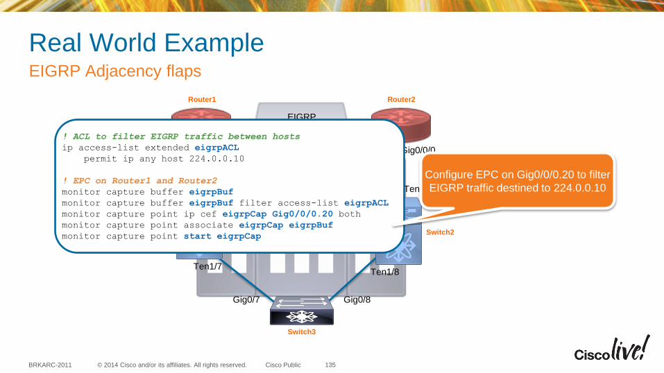
© 2014 Cisco and/or its affiliates. All rights reserved. BRKARC-2011 Cisco Public
Router1 Router2
Switch1 Switch2
Switch3
Gig0/7 Gig0/8
Ten1/7 Ten1/8
Ten1/1
Gig0/0/0 Gig0/0/0
Ten1/1
Ten1/3
Ten1/5
Po 1
Ten1/3
Ten1/5
EIGRP
Real World Example EIGRP Adjacency flaps
! ACL to filter EIGRP traffic between hosts
ip access-list extended eigrpACL
permit ip any host 224.0.0.10
! EPC on Router1 and Router2
monitor capture buffer eigrpBuf
monitor capture buffer eigrpBuf filter access-list eigrpACL
monitor capture point ip cef eigrpCap Gig0/0/0.20 both
monitor capture point associate eigrpCap eigrpBuf
monitor capture point start eigrpCap
Configure EPC on Gig0/0/0.20 to filter
EIGRP traffic destined to 224.0.0.10
135
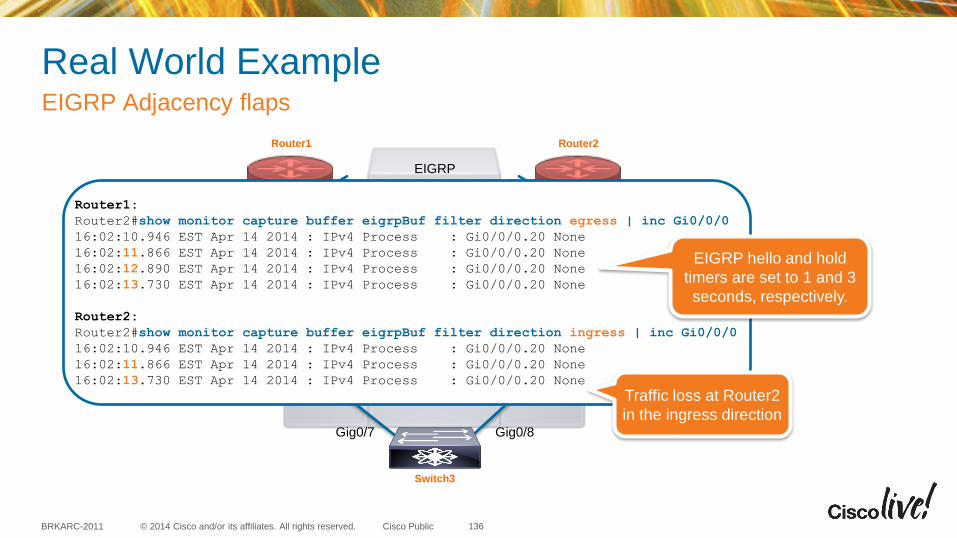
© 2014 Cisco and/or its affiliates. All rights reserved. BRKARC-2011 Cisco Public
Real World Example EIGRP Adjacency flaps
136
Router1 Router2
Switch1 Switch2
Switch3
Gig0/7 Gig0/8
Ten1/7 Ten1/8
Ten1/1
Gig0/0/0 Gig0/0/0
Ten1/1
Ten1/3
Ten1/5
Po 1
Ten1/3
Ten1/5
EIGRP
Router1:
Router2#show monitor capture buffer eigrpBuf filter direction egress | inc Gi0/0/0
16:02:10.946 EST Apr 14 2014 : IPv4 Process : Gi0/0/0.20 None
16:02:11.866 EST Apr 14 2014 : IPv4 Process : Gi0/0/0.20 None
16:02:12.890 EST Apr 14 2014 : IPv4 Process : Gi0/0/0.20 None
16:02:13.730 EST Apr 14 2014 : IPv4 Process : Gi0/0/0.20 None
Router2:
Router2#show monitor capture buffer eigrpBuf filter direction ingress | inc Gi0/0/0
16:02:10.946 EST Apr 14 2014 : IPv4 Process : Gi0/0/0.20 None
16:02:11.866 EST Apr 14 2014 : IPv4 Process : Gi0/0/0.20 None
16:02:13.730 EST Apr 14 2014 : IPv4 Process : Gi0/0/0.20 None
Traffic loss at Router2
in the ingress direction
EIGRP hello and hold
timers are set to 1 and 3
seconds, respectively.
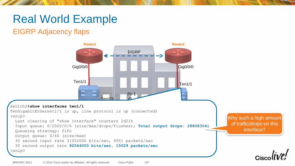
© 2014 Cisco and/or its affiliates. All rights reserved. BRKARC-2011 Cisco Public
Real World Example EIGRP Adjacency flaps
Switch 3
137
Router1 Router2
Switch1 Switch2
Switch3
Gig0/7 Gig0/8
Ten1/7 Ten1/8
Ten1/1
Gig0/0/0 Gig0/0/0
Ten1/1
Ten1/3
Ten1/5
Po 1
Ten1/3
Ten1/5
EIGRP
Switch2#show interfaces ten1/1
TenGigabitEthernet1/1 is up, line protocol is up (connected)
<snip>
Last clearing of "show interface" counters 2d21h
Input queue: 0/2000/0/0 (size/max/drops/flushes); Total output drops: 288083041
Queueing strategy: fifo
Output queue: 0/40 (size/max)
30 second input rate 31052000 bits/sec, 9951 packets/sec
30 second output rate 92544000 bits/sec, 15029 packets/sec
<snip>
Why such a high amount
of traffic/drops on this
interface?
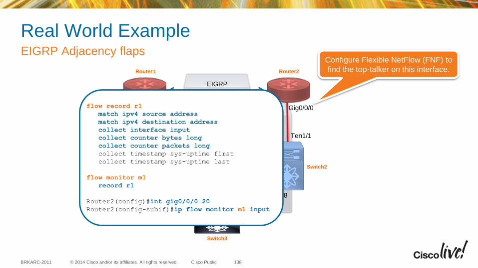
© 2014 Cisco and/or its affiliates. All rights reserved. BRKARC-2011 Cisco Public
Real World Example EIGRP Adjacency flaps
Switch 1
138
Router1 Router2
Switch1 Switch2
Switch3
Gig0/7 Gig0/8
Ten1/7 Ten1/8
Ten1/1
Gig0/0/0 Gig0/0/0
Ten1/1
Ten1/3
Ten1/5
Po 1
Ten1/3
Ten1/5
EIGRP
flow record r1
match ipv4 source address
match ipv4 destination address
collect interface input
collect counter bytes long
collect counter packets long
collect timestamp sys-uptime first
collect timestamp sys-uptime last
flow monitor m1
record r1
Router2(config)#int gig0/0/0.20
Router2(config-subif)#ip flow monitor m1 input
Configure Flexible NetFlow (FNF) to
find the top-talker on this interface.

© 2014 Cisco and/or its affiliates. All rights reserved. BRKARC-2011 Cisco Public
Real World Example EIGRP Adjacency flaps
Switch 1 Switch2
139
Router1 Router2
Switch1 Switch2
Switch3
Gig0/7 Gig0/8
Ten1/7 Ten1/8
Ten1/1
Gig0/0/0 Gig0/0/0
Ten1/1
Ten1/3
Ten1/5
Po 1
Ten1/3
Ten1/5
EIGRP
Router2#show flow monitor m1 cache format record
IPV4 SOURCE ADDRESS: 10.0.20.178
IPV4 DESTINATION ADDRESS: 10.0.10.178
interface input: Gi0/0/0.20
counter bytes long: 99676416
counter packets long: 292492
timestamp first: 127966104
timestamp last: 129744816
IPV4 SOURCE ADDRESS: 169.254.12.101
IPV4 DESTINATION ADDRESS: 169.254.15.1
interface input: Gi0/0/0.10
counter bytes long: 882653170
counter packets long: 1801333
timestamp first: 128214340
timestamp last: 129747640
This traffic is not normal !!
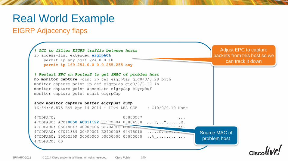
© 2014 Cisco and/or its affiliates. All rights reserved. BRKARC-2011 Cisco Public
Real World Example EIGRP Adjacency flaps
140
Router1 Router2
Switch1 Switch2
Switch3
Gig0/7 Gig0/8
Ten1/7 Ten1/8
Ten1/1
Gig0/0/0 Gig0/0/0
Ten1/1
Ten1/3
Ten1/5
Po 1
Ten1/3
Ten1/5
EIGRP ! ACL to filter EIGRP traffic between hosts
ip access-list extended eigrpACL
permit ip any host 224.0.0.10
permit ip 169.254.0.0 0.0.255.255 any
! Restart EPC on Router2 to get SMAC of problem host
no monitor capture point ip cef eigrpCap gig0/0/0.20 both
monitor capture point ip cef eigrpCap gig0/0/0.10 in
monitor capture point associate eigrpCap eigrpBuf
monitor capture point start eigrpCap
show monitor capture buffer eigrpBuf dump
16:34:46.875 EST Apr 14 2014 : IPv4 LES CEF : Gi0/0/0.10 None
47CDFA70: 00000C07 ....
47CDFA80: AC010050 AC011122 8100000A 08004500 ,..P,.."......E.
47CDFA90: 05D48B43 0000FE06 BC7DA9FE 0C65A9FE .T.C..~.<})~.e)~
47CDFAA0: 0F011389 004F0001 E2400003 94475010 [email protected].
47CDFAB0: 1000255F 00000000 00000000 00000000 ..%_............
47CDFAC0: 00
Adjust EPC to capture
packets from this host so we
can track it down
Source MAC of
problem host

© 2014 Cisco and/or its affiliates. All rights reserved. BRKARC-2011 Cisco Public
Real World Example EIGRP Adjacency flaps
Switch3
Traffic flow
STP ROOT !!
Begin tracking down the location
of the problem hosts and find
some interesting changes in the
L2 topology
141
Router1 Router2
Switch1 Switch2
Switch3
Gig0/7 Gig0/8
Ten1/7 Ten1/8
Ten1/1
Gig0/0/0 Gig0/0/0
Ten1/1
Ten1/3
Ten1/5
Po 1
Ten1/3
Ten1/5
EIGRP
STP Blocking port !!
X
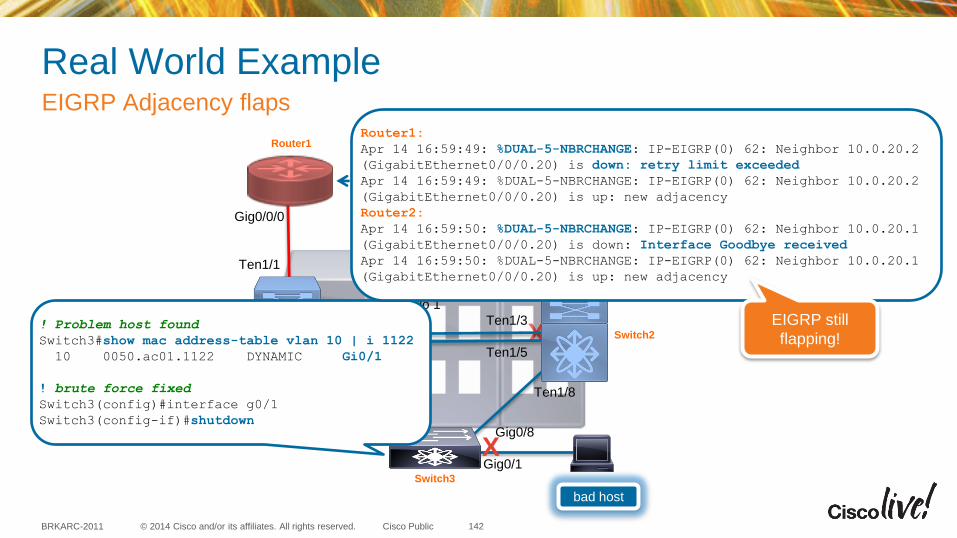
© 2014 Cisco and/or its affiliates. All rights reserved. BRKARC-2011 Cisco Public
Real World Example EIGRP Adjacency flaps
Router 1
Switch 1
142
X
bad host
X Gig0/1
Router1 Router2
Switch1 Switch2
Switch3
Gig0/7 Gig0/8
Ten1/7 Ten1/8
Ten1/1
Gig0/0/0 Gig0/0/0
Ten1/1
Ten1/3
Ten1/5
Po 1
Ten1/3
Ten1/5
EIGRP
! Problem host found
Switch3#show mac address-table vlan 10 | i 1122
10 0050.ac01.1122 DYNAMIC Gi0/1
! brute force fixed
Switch3(config)#interface g0/1
Switch3(config-if)#shutdown
Router1:
Apr 14 16:59:49: %DUAL-5-NBRCHANGE: IP-EIGRP(0) 62: Neighbor 10.0.20.2
(GigabitEthernet0/0/0.20) is down: retry limit exceeded
Apr 14 16:59:49: %DUAL-5-NBRCHANGE: IP-EIGRP(0) 62: Neighbor 10.0.20.2
(GigabitEthernet0/0/0.20) is up: new adjacency
Router2:
Apr 14 16:59:50: %DUAL-5-NBRCHANGE: IP-EIGRP(0) 62: Neighbor 10.0.20.1
(GigabitEthernet0/0/0.20) is down: Interface Goodbye received
Apr 14 16:59:50: %DUAL-5-NBRCHANGE: IP-EIGRP(0) 62: Neighbor 10.0.20.1
(GigabitEthernet0/0/0.20) is up: new adjacency
EIGRP still
flapping!
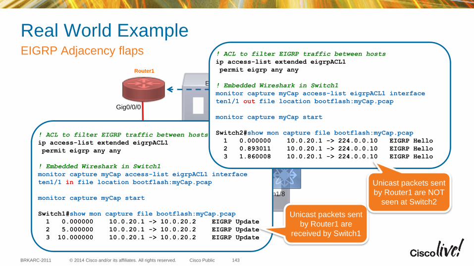
© 2014 Cisco and/or its affiliates. All rights reserved. BRKARC-2011 Cisco Public
Router1 Router2
Switch1 Switch2
Switch3
Gig0/7 Gig0/8
Ten1/7 Ten1/8
Ten1/1
Gig0/0/0 Gig0/0/0
Ten1/1
Ten1/3
Ten1/5
Po 1
Ten1/3
Ten1/5
EIGRP
Real World Example EIGRP Adjacency flaps
Router 1
Switch 1 Switch2
Gig2/1 ! ACL to filter EIGRP traffic between hosts
ip access-list extended eigrpACL1
permit eigrp any any
! Embedded Wireshark in Switch1
monitor capture myCap access-list eigrpACL1 interface
ten1/1 in file location bootflash:myCap.pcap
monitor capture myCap start
Switch1#show mon capture file bootflash:myCap.pcap
1 0.000000 10.0.20.1 -> 10.0.20.2 EIGRP Update
2 5.000000 10.0.20.1 -> 10.0.20.2 EIGRP Update
3 10.000000 10.0.20.1 -> 10.0.20.2 EIGRP Update
! ACL to filter EIGRP traffic between hosts
ip access-list extended eigrpACL1
permit eigrp any any
! Embedded Wireshark in Switch1
monitor capture myCap access-list eigrpACL1 interface
ten1/1 out file location bootflash:myCap.pcap
monitor capture myCap start
Switch2#show mon capture file bootflash:myCap.pcap
1 0.000000 10.0.20.1 -> 224.0.0.10 EIGRP Hello
2 0.893011 10.0.20.1 -> 224.0.0.10 EIGRP Hello
3 1.860008 10.0.20.1 -> 224.0.0.10 EIGRP Hello
Unicast packets sent
by Router1 are
received by Switch1
Unicast packets sent
by Router1 are NOT
seen at Switch2
143
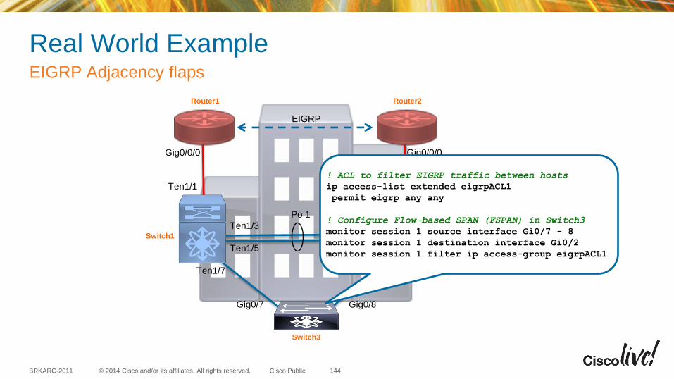
© 2014 Cisco and/or its affiliates. All rights reserved. BRKARC-2011 Cisco Public
Real World Example EIGRP Adjacency flaps
144
Router1 Router2
Switch1 Switch2
Switch3
Gig0/7 Gig0/8
Ten1/7 Ten1/8
Ten1/1
Gig0/0/0 Gig0/0/0
Ten1/1
Ten1/3
Ten1/5
Po 1
Ten1/3
Ten1/5
EIGRP
! ACL to filter EIGRP traffic between hosts
ip access-list extended eigrpACL1
permit eigrp any any
! Configure Flow-based SPAN (FSPAN) in Switch3
monitor session 1 source interface Gi0/7 - 8
monitor session 1 destination interface Gi0/2
monitor session 1 filter ip access-group eigrpACL1
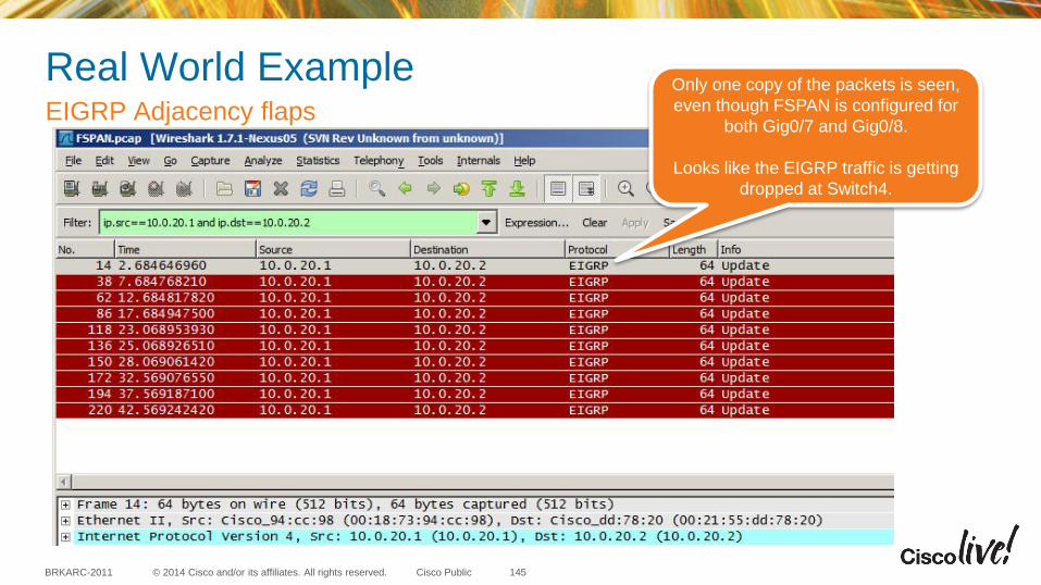
© 2014 Cisco and/or its affiliates. All rights reserved. BRKARC-2011 Cisco Public
Real World Example EIGRP Adjacency flaps
Router 1 Router 1
Switch 1 Switch 2
Switch 3
Gig0/7 Gig0/8
Gig2/7 Gig1/8
Gig2/1
Gig0/0 Gig0/0
Gig1/1
Gig2/3
Gig2/5
Po 1
Gig1/3
Gig1/5
EIGRP
Only one copy of the packets is seen,
even though FSPAN is configured for
both Gig0/7 and Gig0/8.
Looks like the EIGRP traffic is getting
dropped at Switch4.
145
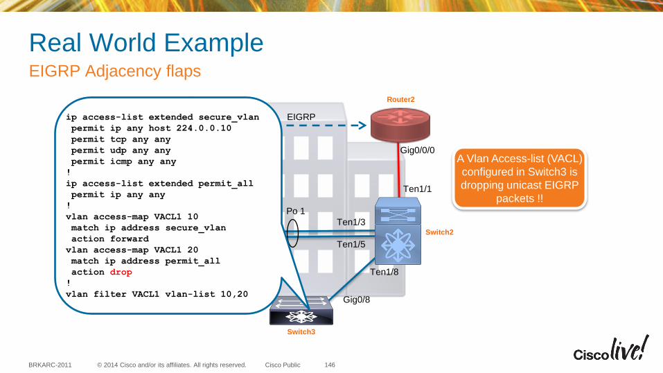
© 2014 Cisco and/or its affiliates. All rights reserved. BRKARC-2011 Cisco Public
Real World Example EIGRP Adjacency flaps
146
Router1 Router2
Switch1 Switch2
Switch3
Gig0/7 Gig0/8
Ten1/7 Ten1/8
Ten1/1
Gig0/0/0 Gig0/0/0
Ten1/1
Ten1/3
Ten1/5
Po 1
Ten1/3
Ten1/5
EIGRP ip access-list extended secure_vlan
permit ip any host 224.0.0.10
permit tcp any any
permit udp any any
permit icmp any any
!
ip access-list extended permit_all
permit ip any any
!
vlan access-map VACL1 10
match ip address secure_vlan
action forward
vlan access-map VACL1 20
match ip address permit_all
action drop
!
vlan filter VACL1 vlan-list 10,20
A Vlan Access-list (VACL)
configured in Switch3 is
dropping unicast EIGRP
packets !!

Summary and Take Away
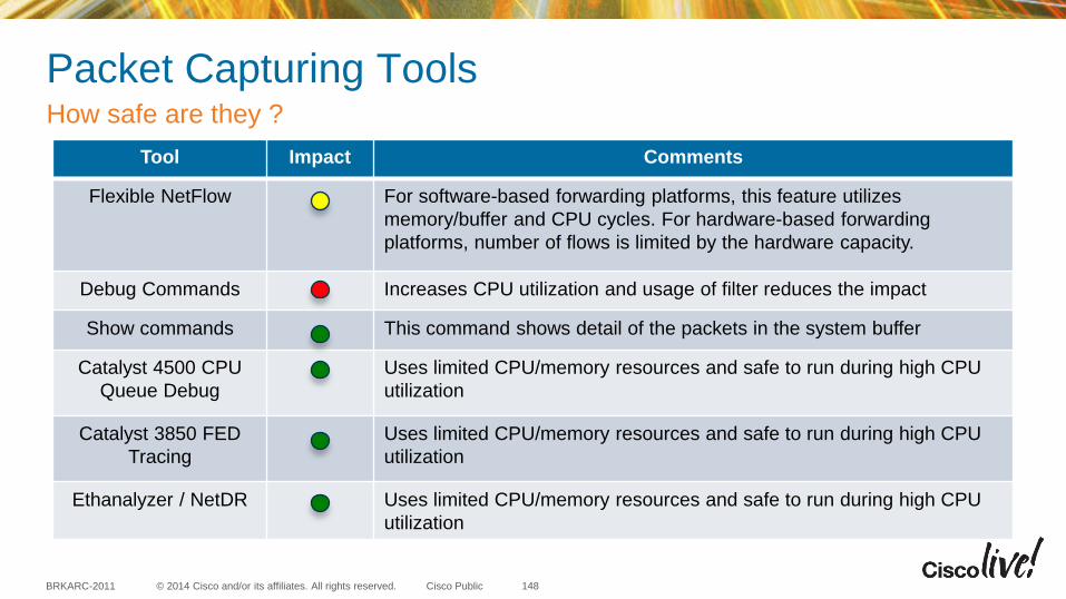
© 2014 Cisco and/or its affiliates. All rights reserved. BRKARC-2011 Cisco Public
Packet Capturing Tools How safe are they ?
Tool Impact Comments
Flexible NetFlow For software-based forwarding platforms, this feature utilizes
memory/buffer and CPU cycles. For hardware-based forwarding
platforms, number of flows is limited by the hardware capacity.
Debug Commands Increases CPU utilization and usage of filter reduces the impact
Show commands This command shows detail of the packets in the system buffer
Catalyst 4500 CPU
Queue Debug
Uses limited CPU/memory resources and safe to run during high CPU
utilization
Catalyst 3850 FED
Tracing
Uses limited CPU/memory resources and safe to run during high CPU
utilization
Ethanalyzer / NetDR Uses limited CPU/memory resources and safe to run during high CPU
utilization
148
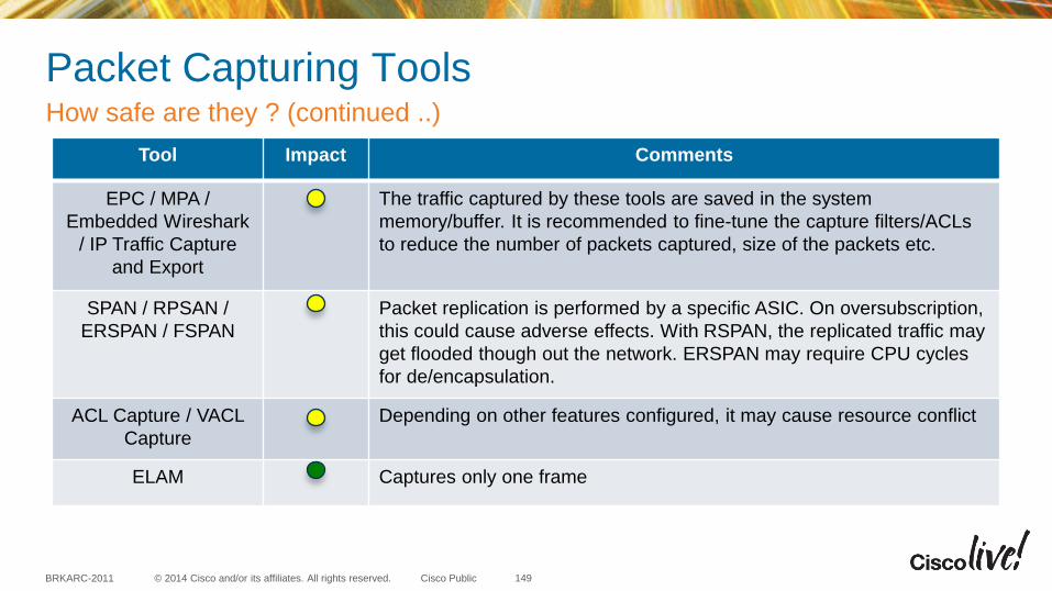
© 2014 Cisco and/or its affiliates. All rights reserved. BRKARC-2011 Cisco Public
Packet Capturing Tools How safe are they ? (continued ..)
Tool Impact Comments
EPC / MPA /
Embedded Wireshark
/ IP Traffic Capture
and Export
The traffic captured by these tools are saved in the system
memory/buffer. It is recommended to fine-tune the capture filters/ACLs
to reduce the number of packets captured, size of the packets etc.
SPAN / RPSAN /
ERSPAN / FSPAN
Packet replication is performed by a specific ASIC. On oversubscription,
this could cause adverse effects. With RSPAN, the replicated traffic may
get flooded though out the network. ERSPAN may require CPU cycles
for de/encapsulation.
ACL Capture / VACL
Capture
Depending on other features configured, it may cause resource conflict
ELAM Captures only one frame
149
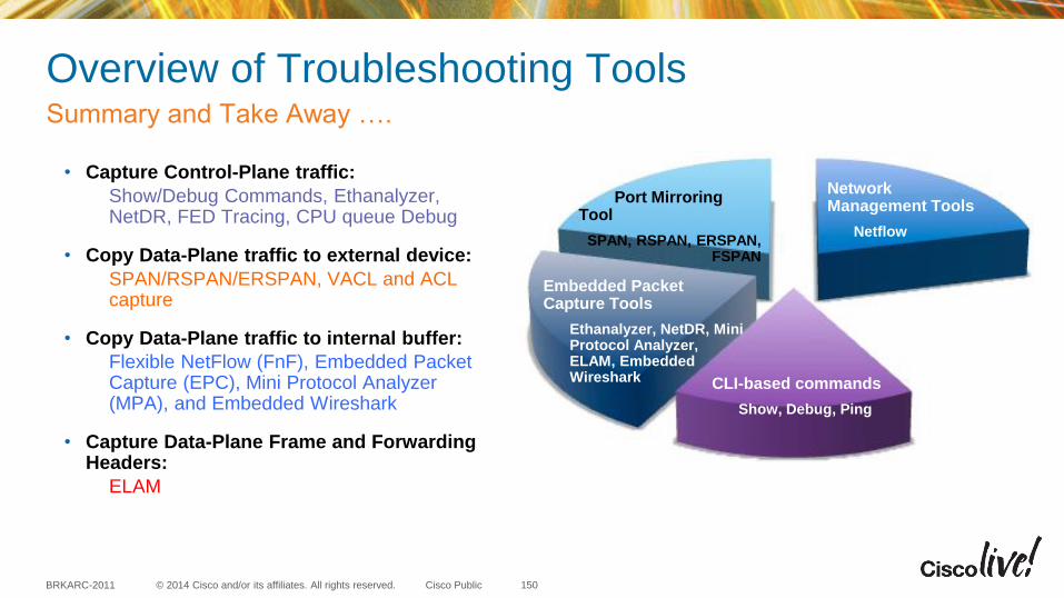
© 2014 Cisco and/or its affiliates. All rights reserved. BRKARC-2011 Cisco Public
Overview of Troubleshooting Tools
• Capture Control-Plane traffic:
Show/Debug Commands, Ethanalyzer, NetDR, FED Tracing, CPU queue Debug
• Copy Data-Plane traffic to external device:
SPAN/RSPAN/ERSPAN, VACL and ACL capture
• Copy Data-Plane traffic to internal buffer:
Flexible NetFlow (FnF), Embedded Packet Capture (EPC), Mini Protocol Analyzer (MPA), and Embedded Wireshark
• Capture Data-Plane Frame and Forwarding Headers:
ELAM
Summary and Take Away ….
150
Embedded Packet Capture Tools
Ethanalyzer, NetDR, Mini Protocol Analyzer, ELAM, Embedded Wireshark
Port Mirroring Tool
SPAN, RSPAN, ERSPAN, FSPAN
CLI-based commands
Show, Debug, Ping
Network Management Tools
Netflow
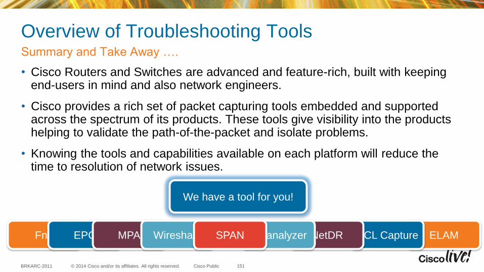
© 2014 Cisco and/or its affiliates. All rights reserved. BRKARC-2011 Cisco Public
Overview of Troubleshooting Tools
• Cisco Routers and Switches are advanced and feature-rich, built with keeping end-users in mind and also network engineers.
• Cisco provides a rich set of packet capturing tools embedded and supported across the spectrum of its products. These tools give visibility into the products helping to validate the path-of-the-packet and isolate problems.
• Knowing the tools and capabilities available on each platform will reduce the time to resolution of network issues.
Summary and Take Away ….
151
FnF
We have a tool for you!
EPC MPA Wireshark ELAM ACL Capture NetDR Ethanalyzer SPAN

© 2014 Cisco and/or its affiliates. All rights reserved. BRKARC-2011 Cisco Public
References
• ELAM Overview: (has links to ELAM examples for 5 different modules) http://www.cisco.com/c/en/us/support/docs/switches/nexus-7000-series-switches/116648-technote-product-00.html
• Catalyst 6500 Series Switches NetDR Tool for CPU-Bound Packet Captures: http://www.cisco.com/c/en/us/support/docs/switches/catalyst-6500-series-switches/116475-technote-product-00.html
• High CPU Troubleshooting in Catalyst 3850 with “FED Tracing”: http://www.cisco.com/c/en/us/support/docs/switches/catalyst-3850-series-switches/117594-technote-hicpu3850-00.html
• Troubleshooting High CPU in Catalyst 4500 switches – with CPU Queue Debug:http://www.cisco.com/c/en/us/support/docs/switches/catalyst-4000-series-switches/65591-cat4500-high-cpu.html
ELAM, NetDR, FED Tracing and CPU Queue Debug
152
© 2014 Cisco and/or its affiliates. All rights reserved. BRKARC-2011 Cisco Public
References
• Flexible NetFlow - Data Sheets, Q&A and White Paper http://www.cisco.com/en/US/products/ps6965/products_ios_protocol_option_home.html
• Migrating from Traditional to Flexible NetFlow http://www.cisco.com/en/US/prod/collateral/iosswrel/ps6537/ps6555/ps6601/ps6965/white_paper_c11-545581.html
• NetFlow Version 9 http://www.cisco.com/en/US/products/ps6645/products_ios_protocol_option_home.html
• Flexible NetFlow - Data Sheets and Literature http://www.cisco.com/en/US/products/ps6601/prod_literature.html
• Cisco IOS Performance Monitor and Mediatrace Whitepaper: http://www.cisco.com/en/US/solutions/collateral/ns340/ns856/ns156/ns1094/whitepaper_c11-653899.html
Flexible NetFlow
153

© 2014 Cisco and/or its affiliates. All rights reserved. BRKARC-2011 Cisco Public
References
• Cisco IOS Embedded Packet Capture – Data Sheet: http://www.cisco.com/en/US/prod/collateral/iosswrel/ps6537/ps6555/ps9913/datasheet_c78-502727.html
• Utilizing the New Packet Capture Feature – Cisco Support Community: https://supportforums.cisco.com/docs/DOC-5799
• Embedded Wireshark – Configuration Guide: http://www.cisco.com/en/US/docs/switches/lan/catalyst4500/15.1/XE_330SG/configuration/guide/wireshrk.html
• Mini Protocol Analyzer – Configuration Guide for 12.2SX release: http://www.cisco.com/en/US/docs/switches/lan/catalyst6500/ios/12.2SX/configuration/guide/mpa.html
Embedded Packet Capture Tools
154
© 2014 Cisco and/or its affiliates. All rights reserved. BRKARC-2011 Cisco Public
Overview of Troubleshooting Tools
• Cisco Medianet offers a set of tools to monitor the network, its performance and business applications. It is highly encouraged to know Medianet Architecture and usage. http://www.cisco.com/web/solutions/trends/medianet/index.html
• Cisco Prime delivers next-gen management infrastructure by simplifying network management, improving operational efficiency and delivering predictable services. http://www.cisco.com/en/US/prod/netmgtsw/prime.html
• Cisco IOS Embedded Event Manager (EEM) provides a real-time network event detection and onboard automation. http://www.cisco.com/en/US/products/ps6815/products_ios_protocol_group_home.html
• Cisco IP Service Level Agreements (SLAs) assures network service levels and proactively monitors network health and performance. http://www.cisco.com/en/US/products/ps6602/products_ios_protocol_group_home.html
More to know and learn ….
155
© 2014 Cisco and/or its affiliates. All rights reserved. BRKARC-2011 Cisco Public
Overview of Troubleshooting Tools
• To learn more about troubleshooting with the Support Automation CLI shown in the “EIGRP Adjacency flaps - Netflow Top Talkers” demo. Please visit us in the Services area: World of Solutions – “Personalize Your Support” booth http://tools.cisco.com/squish/D6a55
More to know and learn ….
156
© 2014 Cisco and/or its affiliates. All rights reserved. BRKARC-2011 Cisco Public
Relevant Sessions at CiscoLive 2014 Breakout Sessions:
• BRKNMS-2030 - Onboard Automation with Cisco IOS Embedded Event Manager
• BRKNMS-3021 - Advanced Cisco IOS Device Instrumentation
• BRKCOL-2343 - Implementing Optimal Video Collaboration with Medianet
• BRKCDN-1113 - Enhanced Management of Video with Media Monitoring
• BRKEVT-2815 - Medianet Traffic and Device awareness for intelligent services
• BRKEVT-2807 - Enterprise Video Network Performance Analysis with Medianet
• BRKRST-2512 - Validating QoS using Medianet Media Awareness
8-Hour Instructor-Led Lab:
• LTREVT-2300 - Enterprise Medianet: Video Applications and Network Design Lab
• LTRNMS-2001 - Advanced Network Automation and Solutions using Cisco IOS EEM
8-Hour Technical Seminar:
• TECCRS-3000 - Smart Operations with Embedded Event Manager + Lab
• TECNMS-3043 - Getting Network Visibility via Cisco IP SLA
157
© 2014 Cisco and/or its affiliates. All rights reserved. BRKARC-2011 Cisco Public
Table Topic: Experiences with Cisco Services Abstract: Services will play a key role in Cisco's goal to be the #1 IT company. This Table Topic session offers our customers and partners the opportunity to have a candid discussion with a Distinguished Engineer from Cisco’s Services organization regarding their interactions with Cisco Services (e.g., opening a case with TAC, obtaining an assessment from Advanced Services, using a Smart Service [e.g., SMARTNet Total Care], using the Cisco Support Communities, and etc.). Cisco Services would like you, our customers and partners, to help us answer the following questions. What are we missing? What are your expectations of us? What could we do that would help make Cisco your #1 IT partner?
Join us for a discussion over lunch to explore and partner in future exciting opportunities
Session 1: 05/19/2014 – Noon to 1PM – Moscone Center West - 3rd Floor Lobby
Session 2: 05/20/2014 – Noon to 1PM – Moscone Center West - 3rd Floor Lobby
158
© 2014 Cisco and/or its affiliates. All rights reserved. BRKARC-2011 Cisco Public
Participate in the “My Favorite Speaker” Contest
• Promote your favorite speaker through Twitter and you could win $200 of Cisco Press products (@CiscoPress)
• Send a tweet and include
– Your favorite speaker’s Twitter handle @YogiCisco and @agossettCCIE
– Two hashtags: #CLUS #MyFavoriteSpeaker
• You can submit an entry for more than one of your “favorite” speakers
• Don’t forget to follow @CiscoLive and @CiscoPress
• View the official rules at http://bit.ly/CLUSwin
Promote Your Favorite Speaker and You Could be a Winner
159
© 2014 Cisco and/or its affiliates. All rights reserved. BRKARC-2011 Cisco Public
Complete Your Online Session Evaluation
• Give us your feedback and you could win fabulous prizes. Winners announced daily.
• Complete your session evaluation through the Cisco Live mobile app or visit one of the interactive kiosks located throughout the convention center.
Don’t forget: Cisco Live sessions will be available for viewing on-demand after the event at CiscoLive.com/Online
160
© 2014 Cisco and/or its affiliates. All rights reserved. BRKARC-2011 Cisco Public
Continue Your Education
• Demos in the Cisco Campus
• Walk-in Self-paced Labs
• Table Topics
• Meet the Engineer 1:1 meetings
161


![[8] BRKARC-2003](https://img.pdfslide.us/doc/110x75/55cf970f550346d0338f88e5/8-brkarc-2003.jpg)