Embed Size (px)
Citation preview

INERUMSTraining
Overview of NAC-MPC Amendment Application Docket No. 72-1025
October 27, 2008NAC International is a Wholly Owned Subsidiary of USEC Inc., the World's Leading Supplier of Enriched Uranium Fuel for Commercial Nuclear Power Plants

INERUMSTraining
page 2
Presentation Overview
Introduction / Meeting Objectives
Dairyland Power La Crosse BWR Project Schedule
NAC-MPC Amendment–
Structural and Thermal Evaluations
–
Nuclear Evaluations
Licensing Considerations
Questions
INERUMSTraining
page 3
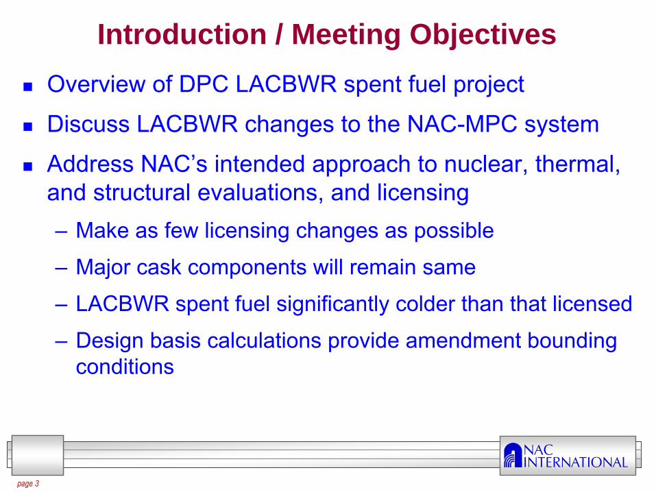
Introduction / Meeting Objectives
Overview of DPC LACBWR spent fuel project
Discuss LACBWR changes to the NAC-MPC system
Address NAC’s intended approach to nuclear, thermal, and structural evaluations, and licensing–
Make as few licensing changes as possible
–
Major cask components will remain same
–
LACBWR spent fuel significantly colder than that licensed
–
Design basis calculations provide amendment bounding conditions

INERUMSTraining
page 4
Dairyland Power Cooperative - La Crosse BWR Spent Fuel Storage Schedule
LACBWR operation 1967 to 1987
1996-2006 limited dismantlement, including RPV removal
2007-2010:–
ISFSI
–
5 NAC-MPC systems loaded in 3rd Quarter of 2010–
DPC June 19, 2008 letter to NRC addressing schedule importance
2011 Full scale dismantlement and license termination plan development

INERUMSTraining
page 5
MPC Amendment Schedule
72 Application–
Pre-application meeting (Meeting in June 2008)
–
Pre-submittal meeting (Current meeting)
–
Amendment request (December 2008)
–
Post-submittal meeting (January 2009)
–
Draft CoC (November 30, 2009)
71 CoC Amendment Application filed in 4th
Quarter 2009 for NAC-STC

INERUMSTraining
page 6
MPC-LACBWR Design Overview
LACBWR—333 assemblies, 155 Allis-Chalmers and 178 Exxon
LACBWR bounded by YR and CY
32 DFC capacity per canister / TSC (160 total)
All AC assemblies in DFCs
Fuel debris in one DFC
Four additional DFCs available
INERUMSTraining
page 7
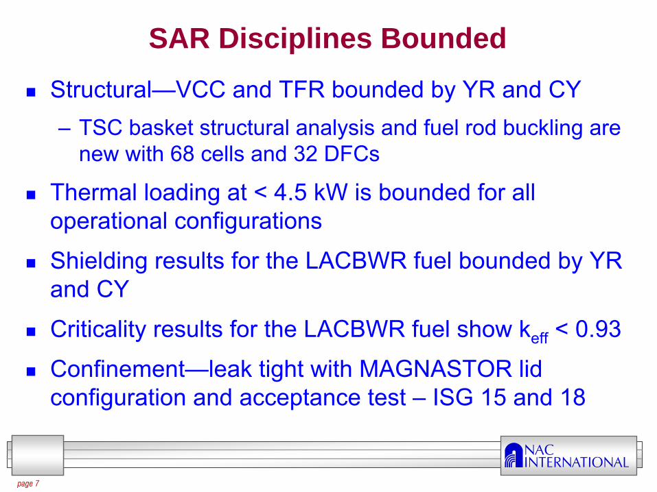
SAR Disciplines Bounded
Structural—VCC and TFR bounded by YR and CY–
TSC basket structural analysis and fuel rod buckling are new with 68 cells and 32 DFCs
Thermal loading at < 4.5 kW is bounded for all operational configurations
Shielding results for the LACBWR fuel bounded by YR and CY
Criticality results for the LACBWR fuel show keff
< 0.93
Confinement—leak tight with MAGNASTOR lid configuration and acceptance test –
ISG 15 and 18

INERUMSTraining
page 8
MPC-LACBWR Design Overview
Actual MPC-YR transfer cask
MPC VCC design with minor modifications
Tube and disk basket with design features and materials the same as MPC basket
Amendment scope limited to expedite NRC’s technical review, certification, and rulemaking

INERUMSTraining
Structural and Thermal Evaluations for the NAC-MPC Amendment
NAC International is a Wholly Owned Subsidiary of USEC Inc., the World's Leading Supplier of Enriched Uranium Fuel for Commercial Nuclear Power Plants.

INERUMSTraining
page 10
Structural Evaluation-Overview
LACBWR will employ the existing
YR transfer cask
Bounding YR canister weight precludes the need for additional evaluation of transfer cask
Yankee Rowe LACBWR
Canister OD (in) 70.64 70.64
Canister length (in) 122.5 116.05
Lid thickness (in) 3 / 5 7
Liner ID (in) 79 79
VCC OD (in) 128 128
VCC length (in) 160 160
Liner thickness (in) 3.5 2.5
Number of assemblies 36 68
Assembly weight (lb) 850 400
Total fuel weight (lb) 30,600 27,200
Loaded canister weight 54,700 53,700
No re-analysis of transfer cask

INERUMSTraining
page 11
Structural Evaluation— Vertical Concrete Cask (VCC)
LACBWR storage system will employ the existing
YR concrete cask
reinforcement / pedestal design
YR heat load of 12.5 kW bounds the largest expected value of < 4.5 kW per canister and bounds thermal stresses
YR design basis calculations provide bounding conditions for LACBWR–
Tornado missiles, seismic, 6-inch drop, extreme heat, air pad lift
No re-analysis of concrete cask

INERUMSTraining
page 12
LACBWR Canister Design
Canister model will be combined with basket model to load the canister shell in tip over evaluation to comply with current license methodology–
Multiple basket orientations considered
Back fill pressure is atmospheric pressure
Weld design follow NAC Magnastor canister design
Yankee Rowe LACBWR
Canister OD (in) 70.64 70.64
Canister length (in) 122.5 116.05
Canister shell thickness (in) 0.625 0.50
Base plate thickness (in) 1.00 1.00
Canister material Type 304L Dual certified 304L 304
Lid thickness (in)Two lids
Structural: 3Shield: 5
Single lid 7
Lid Weld thickness (in) 0.875 0.50

INERUMSTraining
page 13
LACBWR Basket Design
Basket is tube and disk design (NAC-STC, NAC-
MPC, NAC-UMS)
LACBWR contains 32 over sized cells for damaged fuel cans
Ultimate strength for 17-4 PH stainless steel is 135 ksi
Yankee Rowe LACBWR
Disk OD (in) 69.15 69.40
Disk material 17- 4 PH 17- 4 PH
Number of support disks 22 24
Support disk thickness (in) 0.50 0.625
Support disk pitch (in) 4.41 3.83
Number of DFCs 4 32
Ligament thickness (in) 0.88 0.61
Load (lb) per disk per cell 38.6 18.8
Basket Analysis is Structural Focus of Amendment

INERUMSTraining
page 14
Tip Over Evaluation
Determination of peak accelerations used Yankee Rowe LS-Dyna analysis model
Analysis soil properties consisted of 20,000 elastic modulus. Site testing reflected soil modulus of 9,000 psi
Maximum acceleration at basket top is 22.4g’s
The basket DLF was computed to be 1.13 using MPC-CY methodology
5-foot thick Soil model
3-foot thick Concrete pad model
No New Methodologies

INERUMSTraining
page 15
Basket and Canister Tip Over Evaluation
Detailed model of each disk
coarse model of each disk
Axis of rotation
Only one-half of canister is shown
Expanded Model Used to Improve Accuracy
ANSYS 3-D model of the full length basket and canister
Acceleration applied by angular acceleration
Full model captures loading condition of basket on the canister wall
Canister is included in the model
Top stainless steel (304) weldment is included with DFC loading
Multiple basket orientations are to be evaluated

INERUMSTraining
page 16
Basket and Canister Tip Over Evaluation Results
Detailed sectional stresses are computed for 271 sections
SAR shows the 271 sectional stresses for the bounding disks and disk angular orientations
Analysis results in calculation contain all sectional stresses for all disks for all angles
1
23
45
10
6 7
11812
19
9
13 1814 1716
138
136135
134133132131130129128127126125124 123
122
15
121120119
118117
40
4847464544434241
393837363534
33323130292827
26252423222120
80797877
7675
747372706968
676665646362616059
585756555450 535251
49
1021011009998
97969594939291
9089888784 8685
71
116
115
114113112111110
109108107106105
104103
83
139
8281
140 141 142 143 144 145 147
165 166 167 168
172
212209
137
156154
153
152150149148146
163162161160159
232231
158157
182181180179178177176174
164
195194193191
192
173 189188187186185184183
155
210
206205204203202201200199198297296
252
151
222221220219
208207
190175171
170169
218217216215214213211
235234233230229228227226
225
223224
244243242241239
240
238237
236
254253
251
250249
248247246
245
264263
262261
260259
258257
256255
268267266
265
270
269
271
x
z
Table : Support Disk Primary Membrane + Primary Bending Stresses (Pm + Pb), 0° Tip Orientation
Minimum disk margin is +0.30
Minimum top weldment margin is +0.38
SectionSx
(ksi)Sy
(ksi)Sxy (ksi)
Stress Intensity
(ksi)Allowable
Stress (ksi)Margin of
Safety
265 -64.77 -42.32 -26.43 82.26 128.6 0.56
268 -64.77 -42.32 26.43 82.26 128.6 0.56
112 17.11 -26.05 1.31 43.24 128.6 1.97
241 28.59 -17.22 -3.5 43.22 128.6 1.98
242 28.59 -17.22 3.5 43.22 128.6 1.98

INERUMSTraining
page 17
Fuel Rod Buckling Evaluation—Fuel Properties
Yield (Sy) and ultimate (Su) strengths are needed for the irradiated condition
Extensive fuel rod testing documented in “Post Irradiation Evaluation of Fuel Rods from the Lacrosse Boiling Water Reactor,”
June 1976–
Test temperature of 700F envelopes clad normal storage temperature of 443F
Radiation shows increased Sy and Su and loss of ductility
Stress criteria limits fuel rod stresses to Su at unirradiated conditions
Fast Fluence
Sy (ksi) Su (ksi)
0 37 680.4 75 810.5 83 87
1.25 140 141
INERUMSTraining
page 18
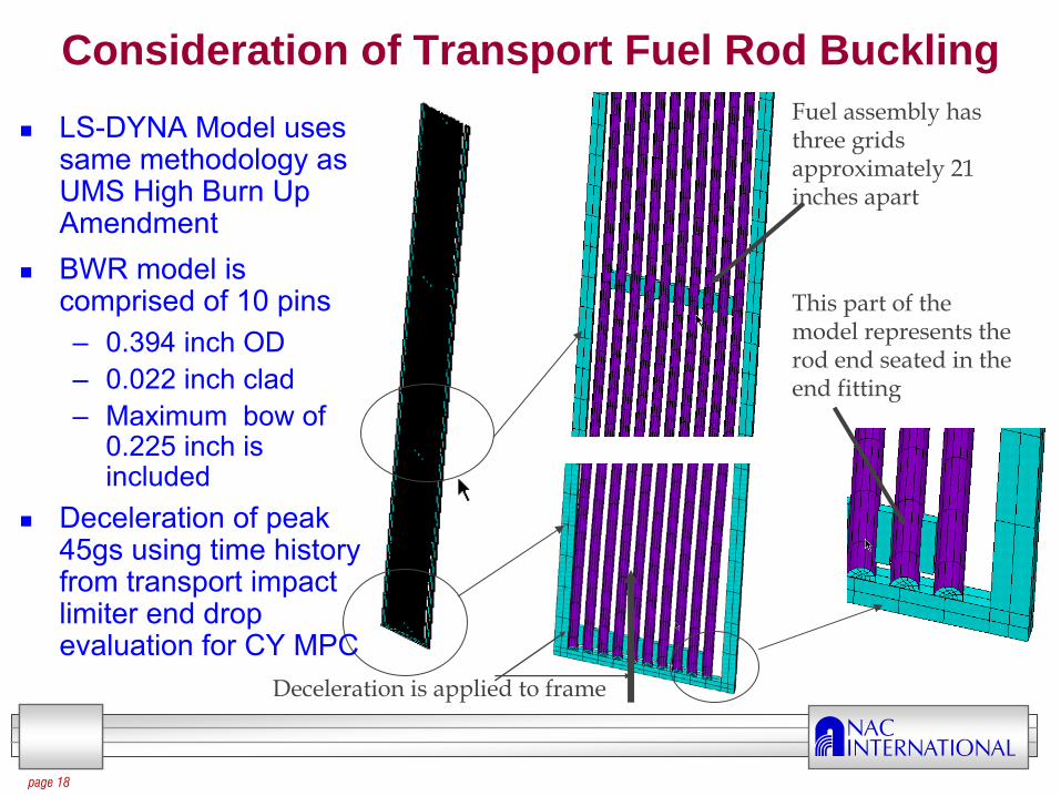
Consideration of Transport Fuel Rod BucklingFuel assembly has three grids approximately 21 inches apart
LS-DYNA Model uses same methodology as UMS High Burn Up Amendment
BWR model is comprised of 10 pins–
0.394 inch OD–
0.022 inch clad–
Maximum bow of 0.225 inch is included
Deceleration of peak 45gs using time history from transport impact limiter end drop evaluation for CY MPC
This part of the model represents the rod end seated in the end fitting
Deceleration is applied to frame

INERUMSTraining
page 19
Fuel Rod Buckling Evaluation—Results
Bilinear properties were modeled using unirradiated material
Maximum stress intensities are determined from LS-DYNA transient analysis
Maximum stresses occurred at the base of the fuel rod at the brick elements representing the end fitting
The stresses of the fuel rods remain in the elastic region
Minimum M.S. (to Su) is +1.75
Analysis confirms undamaged fuel will remain undamaged

INERUMSTraining
page 20
Thermal Evaluation Overview
Maximum canister heat load < 4.5 kW (vs. 12 kW YR)
Steady state analyses were performed without
convection in the annulus region
Due to Low Heat Load, Credit forAnnulus Convection Cooling Not Required

INERUMSTraining
page 21
Details of the Storage Condition Thermal Analysis
Previous license amendments (MPC) have used a series of effective properties (radiation & conduction) for the–
Fuel assembly
–
Damaged fuel can–
Neutron absorber
LACBWR VCC thermal analysis model used a 3-D model comprised of the fuel, fuel tubes, damaged fuel can, basket, canister, and VCC–
Radiation is modeled from canister to inner liner of VCC
Power curve has a peaking factor of 1.36

INERUMSTraining
page 22
Fuel Assembly Thermal Model
Effective properties are determined using a detailed model of the 10x10
Radiation is incorporated using radiation matrix
In-plane and axial properties are computed being temperature dependent
Properties for the fuel tube are also computed using simpler models
X
Y
Z

INERUMSTraining
page 23
Canister-VCC Thermal Model for Storage Condition
Fuel assemblies are modeled as homogeneous using properties from the detailed fuel assembly model
Maximum heat load is 4.5 kW
Effective properties for the fuel tubes are also included
Only radiation is simulated between the canister and VCC inner liner
Solar insolance and film coefficients are applied to VCC exterior surfaces
X
Y
Z
VCC

INERUMSTraining
page 24
Detailed Basket Thermal Model
Each support disk and aluminum disk are modeled
Top end weldment is also included
Gaps between the disks and the canister shell include radiation and conduction in helium
Following conditions are evaluated as steady state:-40F, 75F, 105F, 125F
X
Y
Z

INERUMSTraining
page 25
Thermal Results for Storage Condition
System design and heat load does not challenge fuel clad allowables
Time limit for fuel clad/basket for the all vents blocked
condition is unlimited
Fire condition is bounded by the Yankee Rowe MPC condition
ConditionSupport
Disks(°F)
HeatTransfer
Disks(°F)
TopWeld.(°F)
BottomWeld.(°F)
FuelTubes/DFC(°F)
CanisterShell(°F)
FuelClad(°F)
Avg. Helium
(°F)
75F 437 436 388 352 438/404 349 443 359
Allowable 650 650 800 800 800 800 808 N/A
-40F 370 368 313 293 371/336 280 377 289
105F 454 452 405 368 454/420 365 459 375
133F 465 463 416 379 465/431 377 470 387
Allowable 800 700 800 800 800 800 1058 N/A

INERUMSTraining
page 26
3-D ANSYS LACBWR Transfer Cask Model
3-D ANSYS canister-basket model will be used–
Heat transfer through water in the annulus between canister and cask is by conduction only
–
Transfer cask model contains separate elements for each layer (lead, NS4, shells)
For the vacuum drying condition, the effective material properties for the fuel, neutron absorber and gaps will include the conductivity of helium–
Minimum pressure of 10 Torr (13 millibar) > 1 millibar implies the gas has the same conductivity as gas with 1 bar pressure (Poling, Prausnitz, O’Connell, 2001)
INERUMSTraining
page 27
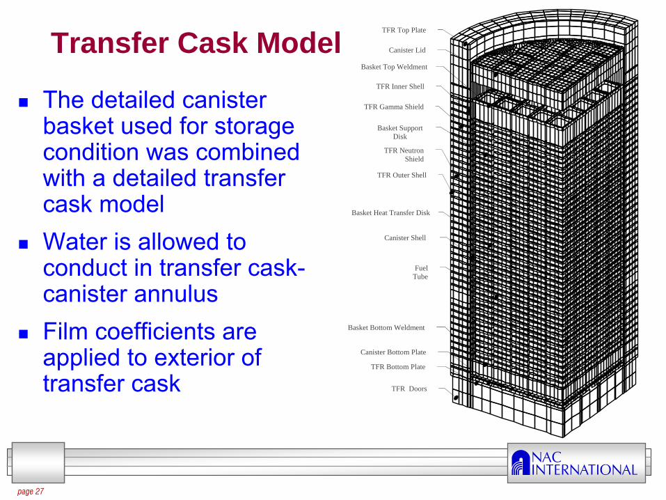
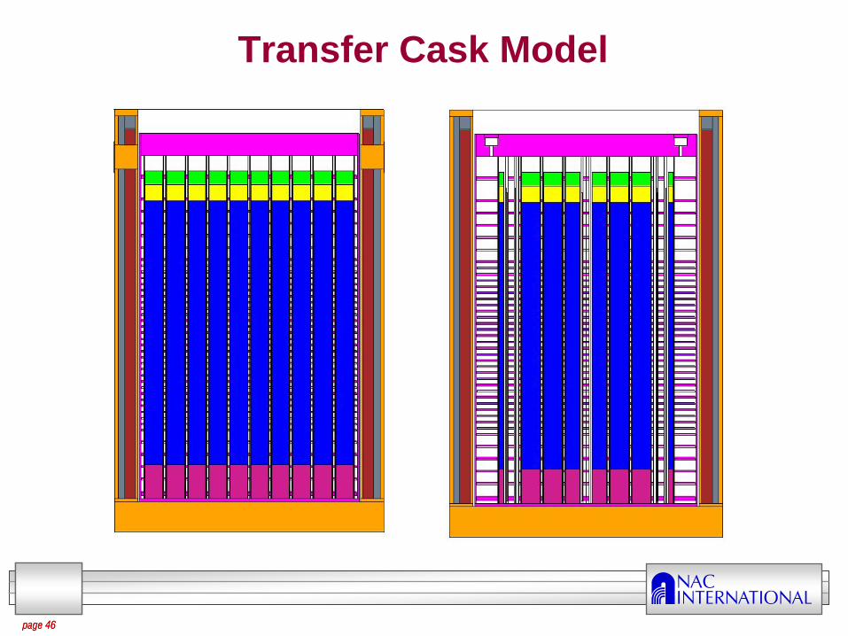
Transfer Cask Model
The detailed canister basket used for storage condition was combined with a detailed transfer cask model
Water is allowed to conduct in transfer cask-
canister annulus
Film coefficients are applied to exterior of transfer cask
XY
Z
TFR Top Plate
Basket Top Weldment
TFR Inner Shell
TFR Gamma Shield
Basket Support Disk
Basket Heat Transfer Disk
TFR Neutron Shield
TFR Outer Shell
Canister Shell
TFR Doors
TFR Bottom Plate
Canister Bottom Plate
Basket Bottom Weldment
Canister Lid
Fuel Tube
INERUMSTraining
page 28
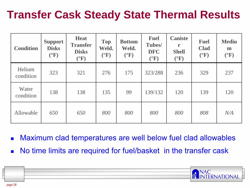
Transfer Cask Steady State Thermal Results
Maximum clad temperatures are well below fuel clad allowables
No time limits are required for fuel/basket in the transfer cask
ConditionSupport
Disks(°F)
HeatTransfer
Disks(°F)
TopWeld.(°F)
BottomWeld.(°F)
FuelTubes/DFC(°F)
Caniste r
Shell(°F)
FuelClad(°F)
Mediu m
(°F)
Heliumcondition 323 321 276 175 323/288 236 329 237
Watercondition 138 138 135 99 139/132 120 139 120
Allowable 650 650 800 800 800 800 808 N/A

INERUMSTraining
page 29
Nuclear Evaluations for the NAC-MPC Amendment
NAC International is a Wholly Owned Subsidiary of USEC Inc., the World's Leading Supplier of Enriched Uranium Fuel for Commercial Nuclear Power Plants.

INERUMSTraining
page 30page 30
Shielding Analysis Method
Codes–
MCNP5: 3-D Monte Carlo Evaluations•
Continuous energy cross-sections –
ENDF/B-VI libraries•
Benchmarked to literature and against previous NAC cask models
–
SCALE 4.3: SAS2H Source Term Evaluations•
27-Group ENDF/B-IV libraries
–
SKYSHINE (NAC-CASC): Site Boundary Analysis
Assemblies Grouped by Type: AC and Exxon
MPC Licensed Source Term MethodNRC Accepted Shielding Method

INERUMSTraining
page 31page 31
Method (continued)
Determine maximum system dose rates by:–
Maximizing source for each fuel group by setting•
Minimum cool time •
Maximum burnup•
Minimum enrichment•
Maximum hardware source
No channels or non-fuel hardware

INERUMSTraining
page 32page 32
Overall source extremely low:–
Maximum burnup –
22 GWd/MTU
(low burnup fuel)–
Minimum cool time –
23 years
–
Minimum enrichment –
3.6 wt% 235U (assembly avg.)
Licensing basis canister heat load ≈
4.2 kW
As loaded heat load expected at 2-3 kW per canister
Source Determination
Fuel (Uranium Oxide) Source < ¼
MPC-YR Level

INERUMSTraining
page 33
Source Term Results
page 33
Parameter AC ExxonLatest Discharge 1982 1987Max. Burnup (MWd/MTU) 22,000 21,000Min. Initial Enrichment (wt % 235U)
3.6 3.6
Min. Cool Time (years) 28 23Decay Heat (W/assembly) 63 61Neutron Source (n/sec) 2.13E+06 1.54E+06Gamma Source (γ/sec) 2.79E+12 2.81E+12Hardware Source (γ/sec/kg) 3.08E+11 5.72E+11Cobalt impurity in steel/inconel
(ppm)
2000 2000

INERUMSTraining
page 34
Source Profile
Axial burnup profile based on site-specific data provided in 10 axial nodes–
Nodes from LACBWR data
–
Low burnup fuel with burnup peak of 1.36
Source profile determination–
Photon source equal to relative burnup
–
Neutron source equal to relative burnup raised to 4.22 power
page 34

INERUMSTraining
page 35
Source Profile (continued)
page 35
0.0
0.5
1.0
1.5
2.0
2.5
3.0
3.5
4.0
0% 10% 20% 30% 40% 50% 60% 70% 80% 90% 100%
Relative
Axial Sou
rce
Fraction of Active Fuel Height
Gamma
Neutron

INERUMSTraining
page 36
Hardware Source Activation Fractions
Activation ratios for upper plenum and end fittings based on PNL-6906–
Upper end fitting: 0.1
–
Upper plenum: 0.2
–
Lower end fitting: 0.15
In-core hardware flux factor at 1.0
page 36

INERUMSTraining
page 37page 37
Shielding Evaluations
Discrete shielding evaluations for storage and transfer casks with undamaged and damaged fuel
Consider fuel debris
Transfer cask evaluations for:–
Dry system (bounding)
–
Wet system
Storage cask always dry
Mixed loading of 36 Exxon and 32 AC assemblies–
32 DFCs in outer fuel tubes
–
Exxon fuel may be located in 8 DFC locations “shielded” by AC fuel

INERUMSTraining
page 38page 38
Shielding Evaluations (continued)
Shielding / radiation protection evaluations to be completed–
Transfer cask occupational exposure
–
Storage cask occupational exposure–
ISFSI dose (skyshine) calculations•
Based on a 5 cask array
–
Cask and canister activation evaluations–
Surface contamination release evaluation

INERUMSTraining
page 39
Storage Cask Model
page 39

INERUMSTraining
page 40
Storage Cask Model (continued)
page 40

INERUMSTraining
page 41
Storage Cask Results
Undamaged fuel
Damaged fuel (uranium oxide collects in lower end fitting void space)–
No increase in side surface maximum
–
Increase in air inlet average (approximately double)–
No effect on top or air outlet dose rates due to gravity
Accident condition (loss of 6" of concrete)–
Side 1m maximum: 105 mrem/hr
page 41
LACBWR-MPC CY/YR-MPC (Inc. DFC)Side surface maximum 30 mrem/hr 167 mrem/hrTop surface maximum 19 mrem/hr 76 mrem/hrAir outlet average 38 mrem/hr 191 mrem/hrAir inlet average 2 mrem/hr 117 mrem/hr

INERUMSTraining
page 42
Storage Cask Side Dose Rate Profile
page 42
0
5
10
15
20
25
30
-100 -50 0 50 100 150 200 250 300 350 400
Dos
e R
ate
[mre
m/h
r]
Axial Position [cm]
Fuel Neutron
Fuel Gamma
Fuel N-Gamma
All Hardware
Total

INERUMSTraining
page 43
Storage Cask Top Dose Rate Profile
page 43
0
2
4
6
8
10
12
14
16
18
20
0 20 40 60 80 100 120 140 160 180
Dos
e R
ate
[mre
m/h
r]
Radial Position [cm]
Fuel Neutron
Fuel Gamma
Fuel N-Gamma
All Hardware
Total

INERUMSTraining
page 44
Storage Cask Air Inlet Dose Rate Profile
page 44
0
5
10
15
20
25
30
35
405
1525
3545
55
65
75
85
95
105
115
125
135
145155
165175
185195
205215
225
235
245
255
265
275
285
295
305
315
325335
345355
Total [mrem/hr]

INERUMSTraining
page 45
Storage Cask Air Outlet Dose Rate Profile
page 45
0.0
0.5
1.0
1.5
2.0
2.59
27
45
63
81
99
117
135
153
171189
207
225
243
261
279
297
315
333
351
Total [mrem/hr]
INERUMSTraining
page 46
Transfer Cask Model
page 46

INERUMSTraining
page 47
Transfer Cask Model (continued)
page 47

INERUMSTraining
page 48
Transfer Cask Results
Undamaged fuel
Damaged fuel (uranium oxide collects in lower end fitting void space)–
No increase in side surface maximum–
No effect on top dose rates due to gravity–
Increase in bottom dose rates (76 mrem/hr maximum for dry conditions)
page 48
LACBWR-MPC CY/YR-MPC (Inc. DFC)Side surface maximum 68 mrem/hr (wet)
102 mrem/hr (dry)
455 mrem/hr (dry)
Top surface maximum 471 mrem/hr (wet)
599 mrem/hr (dry)
2179 mrem/hr (dry)
Bottom surface maximum 24 mrem/hr (wet)
54 mrem/hr (dry)
436 mrem/hr (dry)

INERUMSTraining
page 49
Transfer Cask Side Dose Rate Profile (Dry)
page 49
0
20
40
60
80
100
120
-50 0 50 100 150 200 250 300 350
Dos
e R
ate
[mre
m/h
r]
Axial Position [cm]
Fuel Neutron
Fuel Gamma
Fuel N-Gamma
All Hardware
Total

INERUMSTraining
page 50
Transfer Cask Top Dose Rate Profile (Dry)
page 50
0
100
200
300
400
500
600
700
0 20 40 60 80 100 120
Dos
e R
ate
[mre
m/h
r]
Radial Position [cm]
Fuel Neutron
Fuel Gamma
Fuel N-Gamma
All Hardware
Total

INERUMSTraining
page 51
Transfer Cask Bottom Dose Rate Profile (Dry)
page 51
0
10
20
30
40
50
60
0 20 40 60 80 100 120
Dos
e R
ate
[mre
m/h
r]
Radial Position [cm]
Fuel Neutron
Fuel Gamma
Fuel N-Gamma
All Hardware
Total

INERUMSTraining
page 52
Skyshine Model & Results
page 52
-50
-40
-30
-20
-10
0
10
20
30
40
50
-50 -30 -10 10 30 50
y (f
t)
x (ft)
Pad
Casks
-800
-600
-400
-200
0
200
400
600
800
-800
-600
-400
-200 0
200
400
600
800
y (f
t)
x (ft)
Interpolated 25 mrem/yr Footprint
ISFSI Pad
Rectangular Controlled Area Boundary

INERUMSTraining
page 53page 53
Criticality Analysis Method
Code –
MCNP5–
ENDF-B/VI cross section set
Analysis Steps–
Construct detailed 3-D model
–
Most reactive basket configuration–
Optimum moderator determination
–
Inclusion of damaged fuel•
Including preferential flooding and optimum debris configuration
Revised Basket Requires Detailed Evaluation

INERUMSTraining
page 54page 54
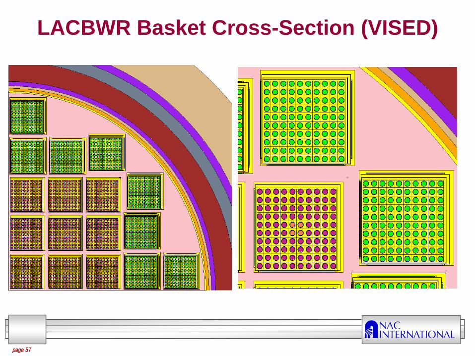
3-D Models
Complete basket detail
Simplified cask structure (primary shields modeled)
Criticality control by flux traps in combination with fixed absorber panels
Absorber panels are attached to outside of tubes
Storage and transfer systems evaluated in vertical configuration only–
Transport to consider axial payload shift

INERUMSTraining
page 55page 55
LACBWR Basket Cross-Section

INERUMSTraining
page 56page 56
LACBWR Basket Cross-Section (VISED)
INERUMSTraining
page 57page 57
LACBWR Basket Cross-Section (VISED)

INERUMSTraining
page 58page 58
LACBWR Basket Cross-Section (VISED)

INERUMSTraining
page 59page 59
LACBWR – Unclad Rod Array (VISED)

INERUMSTraining
page 60page 60
Assembly Information
LACBWR used two primary steel clad assembly types–
AC and Exxon
Exxon fuel assembly –
Max. 3.71 wt% 235U average enrichment•
Radial discrete enrichment pattern
•
Evaluated to demonstrate adequacy of evaluating an “average”
enrichment assembly
–
Maximum 96 fuel rods (4 inert rods)–
AC fuel has 2 types•
Max. 3.64 wt% 235U and 3.94 wt% 235U
•
100 fuel rods (no inert rods)•
Larger diameter pellet than Exxon Nuclear fuel

INERUMSTraining
page 61page 61
Assembly Information
Based on reactor primary coolant chemistry and sipping evaluations, all AC assemblies are considered to be damaged for placement in the dry storage and transport system (note: not all AC assemblies are characterized as having clad breaches)
Exxon assemblies undamaged based on preliminary review–
Evaluated for potential insertion into DFC
–
Less reactive than AC assemblies

INERUMSTraining
page 62
Baseline Reactivity Comparisons
Transfer cask analysis at stacked disk basket design maximum reactivity configuration
AC fuel assembly most reactive when considering full cask load of any one fuel type–
EX 3.71 wt% 235U keff
+2
= 0.854–
AC 3.64 wt% 235U keff
+2
= 0.881–
AC 3.94 wt% 235U keff
+2
= 0.903
Due to assignment to DFCs, AC fuel not permitted in center 36 fuel tubes
page 62
Steel Clad Low Reactivity Fuel

INERUMSTraining
page 63page 63
Tolerance and Shift Analysis Method
Evaluated basket tolerances on primary components–
Fuel tube width and thickness
–
Absorber width and thickness–
Disk opening location and size (maximum flux trap)
–
Disk thickness and spacing
Shifting evaluated for fuel assembly within tube and tubes within basket
Components evaluated individually and in combination
Duplicate/Augment YR/CY Analysis Method for LACBWR

INERUMSTraining
page 64page 64
Tolerance and Shift Analysis Results
Evaluated basket tolerances with full load of undamaged EX or AC fuel types –
wet (0.9982 g/cc)
TSC Cavity–
Limited statistically significant information from centered or shifted manufacturing tolerance studies
–
Combination of tolerance characteristics minimizing flux traps increases reactivity significantly (k/>10 over base case)
–
Shifted components increase system reactivity, k/>10

INERUMSTraining
page 65page 65
Damaged Fuel Studies
Within DFCs–
Assemblies with as-built rod configuration (breached)
–
Unclad rod array•
Removal of stainless steel clad parasitic absorber increases reactivity
•
Provides additional space for otherwise under-moderated fuel rod lattice
–
Fuel / Water Mixture
Maximum reactivity for increased pitch unclad rod array of AC Type 2 (3.94 wt% 235U) fuel in DFCs–
keff
+2
= 0.874

INERUMSTraining
page 66page 66
Optimum Moderator / Fuel Studies
Determine maximum reactivity moderator in the canister, outside the cask, while considering preferential flooding of the damaged fuel canisters
Optimum moderator for undamaged contents is full density TSC moderator (0.9982 g/cc)
Optimum moderator for DFC configuration is a wet (0.9982 g/cc) DFC with a dry (0.001 g/cc) TSC (i.e., preferential flooding of TSC)–
Due to the large number of high reactivity DFCs and the low efficiency of the neutron absorbers in the dry TSC reactivity of
the EX undamaged and AC damaged configuration increases substantially (k ~ 0.06)

INERUMSTraining
page 67page 67
DFC Optimum Moderator Study
0.30
0.35
0.40
0.45
0.50
0.55
0.60
0.65
0.70
0.75
0.80
0.85
0.90
0.95
1.00
0.00 0.10 0.20 0.30 0.40 0.50 0.60 0.70 0.80 0.90 1.00
k eff
Moderator Density (g/cm3)
Variable DFC & TSC Cavity Moderator Density (Simultaneous)
Vary TSC Cavity ‐ Wet (0.9982 g/cc) DFC
Wet (0.9982 g/cc) TSC Cavity ‐ Variable Density DFC Cavity
Dry (0.0001 g/cc) TSC Cavity ‐ Variable Density DFC Cavity

INERUMSTraining
page 68page 68
Criticality Conclusion
Maximum reactivity for EX undamaged and 3.94 wt% 235U AC at k
of 0.931 versus USL of 0.937
To increase system margin a revised loading pattern preferentially loads AC Type 1 (3.64 wt% 235U) and AC Type 2 Fuel (3.94 wt% 235U)
keff
+2
= 0.9205
Loading of EX fuel assemblies (16) into DFC slots along system x-y
plane axis increases system reactivity
slightly
keff
+2
= 0.9244
Maximum reactivity of system is below USL of 0.9372 under the conservative assumption set–
In particular preferential flooding of the DFCs with loose fuel (no clad)

INERUMSTraining
page 69page 69
Confinement
Revised lid design –
No credible leakage (leak-tight)–
MAGNASTOR configuration–
Single lid with closure ring
ISG-18 compatible closure – Stainless steel TSC and lid
Redundant weld seal design
TSC shell leak tested at fabrication
Lid weld not field leak tested
Port covers field helium leak tested
Final assembly hydro tested
ALARA based design
Drain or VentPort (Typical)
RedundantPort Covers
ConfinementBoundary
ClosureRing
Closure Lid

INERUMSTraining
Licensing Considerations for the NAC-MPC Amendment
NAC International is a Wholly Owned Subsidiary of USEC Inc., the World's Leading Supplier of Enriched Uranium Fuel for Commercial Nuclear Power Plants.

INERUMSTraining
page 71
Licensing Summary NAC Multi-Purpose Canister (NAC-MPC)
Licensing Basis: CoC No. 1025, Amendment 5, July 24, 2007 and NAC-MPC FSAR, Revision 7
LACBWR Amendment Request (FSAR Rev. MPC-08A) to be submitted in December 2008
Desired draft CoC/SER date November 2009
Desired draft final effective date for CoC 1025, Amendment 6 is March 2010
DPC June 19 letter to NRC addressing importance of amendment schedule
INERUMSTraining
page 72
Amendment Request to be Submitted in December 2008
Electronic submittal planned
NAC-MPC FSAR, with “Revision 08A”
on all changed pages and rev bars added to mark changes/additions
All chapters supplemented by MPC-LACBWR Appendix cross-referencing applicable information in base document text
Upon approval, changes to be incorporated into NAC- MPC FSAR, Revision 8

INERUMSTraining
page 73
Conclusion
NAC is committed to the submission of a quality amendment
NAC requests the NRC provide reviewers that have experience with the NAC-MPC or NAC-UMS systems
NAC anticipates limited NRC review because:–
Non-aggressive fuel
–
Only criticality and structural changes are significant–
Thermal and shielding amended to confirm LACBWR bounded by previously licensed MPC designs
–
Changes to other disciplines minor
RIS 2005-27-Rev. 1 would allow for a 7-month completion time (one –
three disciplines) for NRC
review

INERUMSTraining
Questions?