Embed Size (px)
Citation preview

1
Overview of Microbial Fuel Cell (MFC) Recent Advancement
from Fundamentals to Applications: MFC Designs, Major Elements,
and Scalability
Sami G. A. Flimban*1, Taeyoung KimϮ2, Iqbal M.I. Ismail3, and Sang-Eun Oh*1
1Department of Biological Environment, Kangwon National University, Gangwon-do,
Chuncheon, South Korea
2School of Environmental Science and Engineering, Gwangju Institute of Science and
Technology (GIST), 261 Cheomdan-gwagiro, Buk-gu, Gwangju 61005, Republic of
Korea
3Center of Excellence in Environmental Studies, Department of Chemistry, College of
Science, King Abdulaziz University, Jeddah, Saudi Arabia
*Corresponding authors:
[email protected] Phone No: +82-33-250-6449
[email protected] Phone No: +966567358445
ϮSecond first author.
Preprints (www.preprints.org) | NOT PEER-REVIEWED | Posted: 2 November 2018 doi:10.20944/preprints201810.0763.v1
© 2018 by the author(s). Distributed under a Creative Commons CC BY license.

2
Abstract: Fossil fuels and carbon origin resources are affecting our environment. Therefore,
alternative energy sources have to be established to co-produce energy along with fossil fuels
and carbon origin resources until it is the right time to replace them. Microbial Fuel Cell (MFC)
is a promising technology in the field of energy production. Compared to the conventional power
sources it is more efficient and not controlled by Carnot cycle. Its high efficiencies, low noise,
and less pollutant output could make it revolutionize in the power generation industry with a
shift from centrally located generating stations and long-distance transmission lines to dispersed
power generation at load sites.
In this review, several characteristics of the MFC technology will be highlighted. First, a
brief history of abiotic to biological fuel cells and subsequently, microbial fuel cells is presented.
Second, the focus is then shifted to elements responsible for the making MFC working with
effeciency. Setup of the MFC system for every element and their assymbly is then introduced,
followed by an explanation of the working machinary principle. Finally, microbial fuel cell
designs and types of main configurations used are presented along with scalability of the
technology for the proper application.
Keywords: Microbial fuel cell (MFC); fuel cell elements; design; energy generation; Scaling up;
configuration.
Table of Contents
1. Introduction ............................................................................................................................. 3
2. Microbial fuel cell revolution ................................................................................................. 4
3. MFC Elements, Setup, and Working machinery Principle ................................................ 7
Preprints (www.preprints.org) | NOT PEER-REVIEWED | Posted: 2 November 2018 doi:10.20944/preprints201810.0763.v1
3
4. Design of MFCs ..................................................................................................................... 14
4.1 Design and Development of Microbial Fuel Cells ................................................................. 15
4.2 Double-chambered fuel cells .................................................................................................. 16
4.3 Single Chambered Fuel cells .................................................................................................. 20
4.4 Stacked Microbial fuel cell ..................................................................................................... 22
5. Scalability of MFC ................................................................................................................ 31
6. Picturing the difficulties when designing and scaling up .................................................. 34
7. Conclusions ............................................................................................................................ 36
8. References .............................................................................................................................. 38
1. Introduction
Conventional waste and wastewater treatment systems need high-energy requirement
depending on the alternative treatment technology, which will consume less energy for efficient
operation. Moreover, with the insufficient use of fossil fuels and their products, global energy
environmental concerns and crises urge the world to find out renewable/sustainable and clean
energy sources [1, 2]. Employing the microorganisms to convert biodegradable waste materials
(substrates), and whatever considered once as expensive organic wastes to dispose of, into
electricity [3-5], grab the attention to MFC and made it the technology of choice [6]. With this
technology, bacteria are attached to the surface of anode electrode forming a biofilm, which is
then used as an electrochemical reaction catalyst to produce electricity. When used for waste and
wastewater treatment, treatment using MFC is effective as it is clean energy, safe, quiet in
performance, low in emissions, highly efficient, and has direct electricity recovery.
Preprints (www.preprints.org) | NOT PEER-REVIEWED | Posted: 2 November 2018 doi:10.20944/preprints201810.0763.v1

4
Herein, the issue of designing and scaling-up MFCs will be addressed, especially with
regard to their prospective configuration. In addition, the history of MFC evolution and
mechanism of how does it work were mentioned briefly. Lastly, some recommendations and
suggestions were listed and discussed with some detals.
2. Microbial fuel cell revolution
On the year 1790, Italian physician and physicist called Luigi Galvani who investigated
the nature and effects of electricity in animal tissue was the first to observe the bioelectric
phenomenon when he noticed twitching of isolated frog leg upon passing a brief electrical
discharge through it, and the term bioelectricity was coined after that observation. On the year
1910, Michael Cresse Potter, a professor of botany at the University of Durham, UK,
demonstrated that organisms could generate a voltage and deliver current when he was
researching how microorganisms degrade organic compounds. Later in 1911, Potter discovered
electrical energy from cell cultures of Escherichia coli and Saccharomyces using platinum
electrodes. This discovery led him to construct a basic microbial fuel cell [7]. In 1931, Cohen at
Cambridge, UK, revived Potter’s idea when he described how a batch of biological fuel cells
produced more than 35V. On the 1960s, the idea of fuel cell became popular when the National
Aeronautics and Space Administration exhibited interest in turning organic waste into electricity
on its long-haul space flights. Algae and bacteria were among the first organisms used in
biological fuel cells. During this period, Rohrback et al. designed the first biological fuel cell in
which Clostridium butyricum was used as a biological material to generate hydrogen by glucose
fermentation [8]. Right after that, biological fuel cells were already commercially available for
use as a power source, but they were unsuccessful. Therefore, they disappeared from the market.
Preprints (www.preprints.org) | NOT PEER-REVIEWED | Posted: 2 November 2018 doi:10.20944/preprints201810.0763.v1

5
On 1966, Williams showed that rice husk is a potential source of lignocellulose as it can produce,
up on fermentation, many useful enzymes and biofuels resulting in 40 mA at 6 V using
biological fuel cells [9]. Also, few more attempts have been done to follow William’s
demonstration [10, 11]. However, the fuel cell revolution started when M. J. Allen and H. Peter
Bennetto from Kings College in London, UK, have developed and demonstrated improved
biological fuel cells using various microorganisms to enhance both the efficiency of electron-
transfer and the reaction rate using mediator systems [12]. Hence, they combined an
understanding of the electron transport chain and significant advancements in technology.
Moreover, to answer the question of how do the electrons get from the electron transport chain to
the anode? Certain electrochemically active bacterial species using no mediator molecules were
discovered by Byung Hong Kim group, (Korean Institute of Science and Technology, South
Korea) to transport electrons to the electrodes [13]. Later, Chaudhuri and Lovely have confirmed
the finding by Byung Hong Kim group by demonstrating that R. ferrireducens microorganism
can recover up to 83% of electrons from glucose oxidation in the presence of Fe3+ without a
mediator.
Preprints (www.preprints.org) | NOT PEER-REVIEWED | Posted: 2 November 2018 doi:10.20944/preprints201810.0763.v1

6
Table 1: MFC History.
Scientist Country Year
Contribution
Luigi Galvani (Physician and
physicist)
Italy 1790 Observe the bioelectric phenomenon
when he noticed twitching of isolated
frog leg upon passing a brief electrical
discharge through it, and the term
bioelectricity was coined after that
observation. Potter, M.C., (Professor of
botany at the
University of
Durham)
Durham, UK 1910
-
1912
Demonstrated that organisms could
generate a voltage and deliver current. Discovered electrical energy from cell
cultures of Escherichia coli and
Saccharomyces using platinum electrodes Cohen, B., Cambridge,
UK 1931 Described how a batch of biological fuel
cells produced more than 35V. Rohrback, G. H.,
Scott, W. R.
and canfield, J.
H.
1962 Designed the first biological fuel cell in
which Clostridium butyricum was used as
a biological material to generate
hydrogen by glucose fermentation Williams, K. R.
1966 Showed that rice husk is a potential
source of lignocellulose as it can produce,
up on fermentation, many useful enzymes
and biofuels resulting in 40mA at 6 V
using biological fuel cells Allen, R. M. &
Bennetto, H. P.
from kings
college in
London, UK
London, UK 1993 Developed and demonstrated improved
biological fuel cells using various
microorganisms to enhance both the
efficiency of electron-transfer and the
reaction rate using mediator systems Chang, I. S.,
Moon, H.,
Bretschger, O.,
Jang, J. K., Park,
H. I., Nealson, K.
H. & Kim, B. H.
from Korean
institute of
science and
technology
(KIST)
South Korea 2006 Discovered that certain electrochemically
active bacterial species using no mediator
molecules transport electrons to the
electrodes.
Preprints (www.preprints.org) | NOT PEER-REVIEWED | Posted: 2 November 2018 doi:10.20944/preprints201810.0763.v1

7
3. MFC Elements, Setup, and Working machinery Principle
Typically, MFC apparatus (Figure 1) consists of two chambers (anodic and cathodic)
made up of glass, polycarbonate or Plexiglas, with a respective electrode of graphite, graphite
felt, carbon paper, carbon-cloth, Pt, Pt black or reticulated vitreous carbon (RVC). These two
chambers are separated by a proton exchange membrane (PEM) (Nafion or Ultrex) [14]. The
anodic chamber contains organic substrates that are metabolized by microbes for growth and
energy production while generating electron and proton. Cathode chamber contains a high
potential electron acceptor to complete the circuit. To increase power density, an ideal electron
acceptor is needed and it must be sustainable with no interference or toxic effect to microbial
community or any other elements of the system in any way. Oxygen worked as an ideal electron
acceptor due to its non-toxic effect and preferred as an oxidizing agent as it simplifies MFC
operation. Instead, a standard oxidizing agent with a suitable electron acceptor such as
ferricyanide can be used [15, 16]. Since microorganisms can produce electrochemically active
substances that may be either metabolic intermediaries or final products of anaerobic respiration
[17], MFC can be defined as a device using microorganisms to convert chemicals into electrical
energy in a catalytic reaction [18]. MFCs are exceptional in using microorganisms to oxidize the
organic matters biologically and to produce and transfer electrons to the anode electrode surface
to form a biofilm. This biofilm is used as a biocatalyst instead of precious metal catalysts such as
platinum (Pt) to perform the required electrochemical redox reaction (catalytic oxidation at the
anode and chemical reduction at the cathode).
At the anode chamber, organic matter is the fuel of MFCs and microorganisms carry out
the degradation of organic compounds by oxidizing (reduces other substances and loses
Preprints (www.preprints.org) | NOT PEER-REVIEWED | Posted: 2 November 2018 doi:10.20944/preprints201810.0763.v1

8
electrons; electron donor) biodegradable substrates to produce CO2, protons, and electrons. The
generated electrons produced from the metabolic activity of microorganisms are transferred to
and collected on the anode electrode surface by redox-active proteins or cytochromes and then
passed to the cathode, thus reacting with the electronic acceptor (usually oxygen) through
electrical circuit (copper wire) [19, 20]. Simultaneously, protons are transferred internally
through the membrane to form water molecule at the cathode. Due to the difference in solution
concentrations, a potential difference is produced between the anode and cathode. The electron
flow through the external electric circuit is responsible for the electric power generation.
At the cathode chamber, usually, an electron acceptor is provided, e.g., oxygen or
ferricyanide, for the reduction of electrons to take place, and among other possible reactions
electrons combine with protons and oxygen forming water molecules, i.e., oxygen is reduced to
water [15, 21].
Usually, the oxygen reduction is catalyzed by a precious metal, such as platinum, and
non-precious metal, such as palladium catalyst [22, 23]. Furthermore, the microorganisms
contain true catalysts because the energy they gained is from the fuel oxidation at the anode.
Thus, this oxidation is not an actual catalysis step, where overall energy loss is created.
Depending on the energy (the bacterial energy gain at the anode and the loss at the cathode), 0.3–
0.5 volts is usually obtained for fuels such as acetic acid or glucose. Almost any substrate of any
biodegradable organic matter and complex organic matter mix, present in human, animal, and
food processing wastewaters, could be used to generate electricity in MFC. Technically,
microorganisms are ideal catalysts and self-regenerating systems that can to produce electrical
energy from a variety of renewable chemical sources. These chemicals are the carbon source for
Preprints (www.preprints.org) | NOT PEER-REVIEWED | Posted: 2 November 2018 doi:10.20944/preprints201810.0763.v1
9
bacteria in MFCs and they could be either simple carbohydrate sources, such as sucrose, glucose
[24], acetate [25], alcohols [26, 27], grape juice [28]; or complex carbon sources such as
wastewaters from different origins [29], starch [30, 31], chocolate industry [32], food processing
[33], beer brewery [34], and sewage sludge [35]; and food industry wastes [36]. As a result of
microorganism’s flexibility in consuming a broad range of fuels harnessed from waste, the MFC
considered globally to be an ideal technology for bioelectricity generation from renewable
biomass.
According to how electrons are transferred from the bacteria to the anode, MFCs can be
classified into two types: mediator and mediatorless MFCs. In mediator type of MFCs,
microorganisms have no electrochemically-active-surface-proteins for transferring electrons to
the anode electrode. As a result, they need agents to help them increase the availability of the
transferred electrons and, to transfer these electrons between the microorganisms and the
electrode at relatively higher concentrations. These agents are called electroactive metabolites (or
mediators). Nevertheless, depending on the microorganism species involved, mediators may be
synthetic, like neutral red; or natural, like sulfate/sulfide [37, 38]. However, the cells are set to
enter the cell electron transport chain and to accept the electrons that are produced using
inorganic mediators under anaerobic conditions. At this point, the mediators cross the outer cell
lipid membranes and plasma wall, and start liberating electrons from the electron transport chain,
which is usually taken up by oxygen and other intermediates. Afterward, the reduced mediator
exits the electron-loaded cell and deposits the carried electrons on the surface of the anode
electrode. Hence, anode electrode becomes negatively charged. Upon releasing the electrons, the
mediator returns to its original oxidized state prepared to repeat the process. By contrast, under
aerobic condition, oxygen (has a higher electronegativity than the mediator) will collect all the
Preprints (www.preprints.org) | NOT PEER-REVIEWED | Posted: 2 November 2018 doi:10.20944/preprints201810.0763.v1

10
electrons. Some mediators have been suggested to be used in microbial fuel cells including
methylene blue, natural red, resorufin or thionine [39]. The reduced mediator is oxidized when it
deposits the carried electrons from the cell to the anode electrode. Through the external circuit,
the electrons are then flow to the cathode electrode (acts as an electron sink) and passes to an
oxidizing material to complete the process. It should be noted that these electrons are consumed
as electric current to power electronic devices before they ultimately get to oxygen at the cathode,
which is what is required for bacterial optimal growth. Due to high costs and toxicity of these
mediators, it is necessary to develop alternatives to improve the power production and decrease
the capital cost making it suitable for wastewater treatment process; mediator-less MFCs.
Furthermore, there are many drawbacks when using exogenous mediators such as short lifetime,
high cost, and toxicity to both the microorganisms and the natural environmental-eco systems.
Nevertheless, when the bacteria produce their own mediators or directly transfer electrons to the
electrode, the system can operate at a high-sustained activity level.
On the other hand, electricity can be generated without mediators using some
microorganisms. The mediator-less type of MFCs has an advantage over the former type, as it is
less costly and non-toxic. They function without exogenous electron carriers, and they mostly
rely on metal-reducing bacteria such as Shewanella [4, 5, 40] including Shewanella putrefaciens
[41]; Rhodoferax [42]; Geobacteraceae [43] [44] including Geobacter sulfuurreducens [4],
Geobacter metalli reducens [45]; Aeromonas hydrophila [46]; and Klebsiella pneumoniae [47].
Nonetheless, when mediatorless MFC is operated, some factors such as presence of
electrochemically active redox enzymes for efficient electron transfer to the anode, fuel
oxidation at the anode, the circuit external resistance, oxygen reduction at the cathode, and
proton transfer through the membrane to the cathode have to be considered as they are limiting
Preprints (www.preprints.org) | NOT PEER-REVIEWED | Posted: 2 November 2018 doi:10.20944/preprints201810.0763.v1

11
the generation of electricity. However, when the membrane proton permeability is poor, the
cathode chamber proton transfer can be a limiting factor. Under these limitations, microbial
activity and electron transfer to the electrode in anode chamber can be reduced due to change in
pH, besides the slow cathode reaction due to limited proton supply [30].
Geobacteraceae sp. transfer electrons directly to the anode via redox enzymes in the
outer membrane. Nevertheless, this mediator-less MFCs, capture monosaccharides and methanol
from food leftovers converting them into hydrogen and food for the bacteria.
For using the bacterial electron flow for electricity generation, this process has to be
apprehended in a fuel cell, and to create a useful current; it is necessary to create a fast, complete,
and non-stoppable circuit. Furthermore, for the microorganisms to feed on a suitable substrate
such as glucose or wastewater, the mediator and the microorganism have to be mixed in one
solution. This solution mix has to be contained in a sealed chamber (the Anode) under an
anaerobic environment in the absence of oxygen (normally slows down bacterial growth)
enforcing the microorganism to use anaerobic respiration. Usually, when substrates are
metabolized in an aerobic environment, electrons in the substrate-containing monosaccharides,
fats, proteins, or other bio-available molecules are biodegraded by the bacteria and electrons are
transferred using bacterial metabolic pathways for cell energy. During this process, oxygen is the
driving force and the ultimate electron acceptor owing to its electrons-high-affinity. Since MFCs
operate under anaerobic environment, none of this electron transfer called aerobic respiration
will occur. Moreover, in an anaerobic environment, cells act differently in using the waste as
substrate molecules, and the amount of energy they receive is greatly reduced with limited
growth. To solve this limitation problem, microorganisms should transfer their electrons to an
Preprints (www.preprints.org) | NOT PEER-REVIEWED | Posted: 2 November 2018 doi:10.20944/preprints201810.0763.v1

12
electrode in the anode solution and, hence, facilitate fuel electrochemical oxidation. Any
electrically conductive path such as copper wire in the presence of a resistor (acts as a break in a
car to slowdown the speed of electron flow not to be quickly depleted) connects this negatively
charged anode creating an external circuit toward another electrode in the cathode chamber. In
the presence of oxygen, the cathode electrode sank in the solution-containing oxidizing agent,
such as oxygen. This agent, in turn, picks up the electrons on the electrode surface to promote the
electrochemical reduction of the oxidant. However, the cathode is positively charged
representing the oxygen sink equivalent at the end of the electron transport chain, the process of
which involves a large volume of circulating gas, which is not practical. Henceforth, a solution
of a solid oxidizing agent, potassium ferricyanide (K3Fe(CN)6), is used. To connect the two
chambers and complete the circuit, there has to be a salt bridge (or electrolytes) or an ion or
proton exchange membrane (PEM) that allows the passage of the produced protons only in one
direction; from the anode toward the cathode chamber.
In principle, the electrons released in MFCs after microbial oxidation of a substrate are
transferred to the anode. Then leave the anode and flow through an external electrical circuit
before reaching the cathode to produce electricity. Finally, these electrons react with protons and
oxygen at the cathode (in the case of an oxygen reduction reaction), producing water as the final
and clean product. Moreover, as long as the current flows over a potential difference, power will
directly be generated from microbial fuel via bacterial catalytic activity [44].
Preprints (www.preprints.org) | NOT PEER-REVIEWED | Posted: 2 November 2018 doi:10.20944/preprints201810.0763.v1

13
Figure 1: Major elements of MFC reactor: 1. Proton Exchange Membrane (PEM)
selective to H+ cation only separating the two chambers; 2. Anode chamber under
anaerobic conditions; 3. Cathode chamber under aerobic (open air) conditions; 4.
Substrate or Biomass for bacteria to feed on; 5. Pure or mixed bacterial culture (a) and
biofilm (b); 6. Nitrogen gas to remove oxygen and maintain the anaerobic condition; 7.
Anode electrode, on which bacterial attachment occurs; 8. Copper wire for transferring
electrons to the cathode; 9. Ω resistor; 10. Cathode electrode to receive the electrons
from the anode; 11. Air oxygen; 12. Electrons reducing agent (Taken from [48]).
Preprints (www.preprints.org) | NOT PEER-REVIEWED | Posted: 2 November 2018 doi:10.20944/preprints201810.0763.v1
14
4. Design of MFCs
Reactor size, shape, and configuration vary widely, it is entirely up to the designer, and
there is no standard design to recommend. Reactor configurations with different volumes,
oxygen supply, membrane area, and electrode spacing can control the MFC overall performance.
Among variously available configurations, double chamber “H” type MFCs have been
typically used due to the existence of ion exchange membrane, which helps in protons diffusion
and in limiting the substrate and oxygen crossover [49]. However, the designs depend merely on
research planning and the aim of the project findings. To date, reactors have been cube-shaped,
cylindrical, horseshoe-shaped, two chamber and single chamber, and H-type configured and
made of glass and various types of plastic, even buckets. Sizes also vary widely with some
reactors having volumes of a few square centimeters and others of up to a square meter with
volumes ranging from microlitres to thousands of liters. Fuel cell design is a significant key
element in the success of a microbial fuel cell (MFC)/microbial electrolysis cell (MEC).
Single-chamber cells have evolved from the original two-chamber design in an attempt to
eliminate the need for a membrane [50]. Moreover, single chamber reactors may show the most
promising results, but this has not discouraged people from using two chamber types. Regarding
construction difficulties, a single chamber reactor can be the harder of the two options. Based
upon assembly of anode and cathode chambers, a simple MFC prototype can either be a double
chambered or single chambered. Besides these two common designs, several adaptations have
been made in a prototype of MFC design and structure [51].
Preprints (www.preprints.org) | NOT PEER-REVIEWED | Posted: 2 November 2018 doi:10.20944/preprints201810.0763.v1

15
Table 2: MFC performance based on configuration.
4.1 Design and Development of Microbial Fuel Cells
Design and construction are one if not the most important elements in MFC. There are
fundamental components of MFCs, which are important in constructions. Electrodes, wire
connection, glass cell and salt bridge have an important role. The salt bridge is replaced with
proton exchange membrane in PEM fuel cell. However, the cost, handling, and the power
generation get enhanced, thus increasing the portability and efficiency of the system. However,
MFC usually consists of an anodic chamber and a cathodic chamber separated by a PEM as
Configuration Inoculum Substrates Electrode Electron
acceptor
Power
Density Ref.
Anode Cathode
Single chamber
Primary clarifier
overflow (mixed
culture)
Glucose
Graphite
carbon fiber
brush treated
with
ammonia
Gas
30% wet-
proofing pt
coated carbon
cloth (type b-
1b)
----------- 2400
mWm-2 [52]
Single-chamber
Domestic
wastewater (14 ml,
∼300 mg-cod/l)
Glucose
Plain toray
carbon paper
(without wet
proofing
30% wet-
proofing pt
coated carbon
paper
----------- 1330
mWm-2 [53]
Two-chamber Anaerobic sludge Glucose Carbone
paper Carbone cloth permanganate
115.60
mWm-2 [54]
Two-chamber
Anaerobic,
Granular,
methanogenic
sludge
Glucose Graphite
plate Graphite plate hexacynoferrate
4310
mWm-2 [55]
Stacked
Mixture of
anaerobic and
aerobic sludge
Sterile
synthetic
influent
containing
sodium acetate
Graphite
granules Graphite rod hexacynoferrate
258
Wm-3 [56]
Stacked
50% Of fresh
activated sewage
Sludge and 50%
Of fresh urine
Neat
Undiluted
Urine
.
Untreated
Carbon
fibre Veil
Coating
activated
Carbon (AC)
paste on
polytetrafluooe
thylene
(PTFE)
----------- 0.8
Wm-3 [57]
Preprints (www.preprints.org) | NOT PEER-REVIEWED | Posted: 2 November 2018 doi:10.20944/preprints201810.0763.v1

16
shown in Figure 1 using a one-chamber MFC by exposing the cathode directly to the air
eliminates the need for the cathodic part. Generally, the two-chamber MFC is operated in water-
cathode mode and single-chamber MFC is operated in air-cathode mode. The major advantage of
two-chamber MFC over the single-chamber MFC is that the performance of cathode can be
improved by controlling pH, purging pure oxygen, increasing flow rate, and adding electron-
mediators in cathode, leading to total enhancement of the MFCs performance.
4.2 Double-chambered fuel cells
In general, this configuration has an anodic and a cathodic chamber separated by a PEM
that facilitates proton transfer from the anode to cathode with simultaneous prevention of oxygen
diffusion into the anode. Therefore, this configuration is generally used for waste treatment with
simultaneous power generation. Both the anode and cathode are different compartments
separated but also connected to each other through a proton exchange membrane (PEM) [58],
which mainly acts as a proton transfer medium to complete the circuit between the two chambers
(Figure 2b). This completes the reaction process and prevents anode from coming into direct
contact with oxygen or any other oxidizers. They typically run in batch mode often with a
chemically defined medium such as glucose or acetate solution to produce higher energy power
output and can be utilized to give power in many inaccessible conditions.
Moreover, in the double chamber, MFC, the relatively longer distance of electrodes can
decrease MFC performance due to an elevation of internal resistance. Choi et al. demonstrated
that for to decrease internal resistance from 672 Ω (103 mW m-2) [59] to 93 Ω (57 mW m-2 ),
electrodes have to be clamped along with membranes with closer electrodes spacing [60]. As a
consequence of this closer of the electrode to the membrane, higher oxygen diffusions from the
Preprints (www.preprints.org) | NOT PEER-REVIEWED | Posted: 2 November 2018 doi:10.20944/preprints201810.0763.v1

17
cathode to anode will eventually occur, which will directly affect the power production and
power density.
Furthermore, Figure 2a illustrates a cubed mini square-shaped compact flat plate MFC
(FPMFC) resembles that of a conventional chemical fuel cell with only a single electrode/PEM
assembly, where the cathode is hot pressed to a Nafion PEM and in contact with an anode to
form an electrode/PEM assembly. The FPMFC with two non-conductive polycarbonate plates is
bolted together. The PEM links the anodic and the cathodic chambers as shown in Figure 2a. The
anodic chamber can be fed with wastewater or other organic biomass, and dry air can be pumped
through the cathodic chamber without any liquid catholyte, both in a continuous flow mode [61].
Nonetheless, Kim et al. have tested the cube type MFCs against the bottle type MFC and they
found that the former produced about 14 times higher power generation (214 mWm-2 power
density with 84 Ω internal resistance) than that of the latter (38 mWm-2 power density with 1272
Ω internal resistance) [62]
The A miniature microbial fuel cell (mini-MFC) of about 2 cm in diameter shown in
Figure 2c, provide a high volume power density of 24 and 10 mWm-2 using reticulated vitreous
carbon (RVC) and graphite felt (GF) electrodes respectively without the addition of exogenous
mediators in the anolyte as reported by [40]. Therefore, they can be useful in powering self-
directed sensors for long-term operations in less accessible regions. The compartments can take
various practical shapes.
Upflow MFC (UMFC) configuration (Figure 2d and 2e) can be suitably designed to scale
up to treat a large volume of wastewater and another carbon source. He et. al. employed two
different UMFC configuration in their experiments and they manage to get a maximum power
Preprints (www.preprints.org) | NOT PEER-REVIEWED | Posted: 2 November 2018 doi:10.20944/preprints201810.0763.v1
18
density of 170 mW m-2 with 84 Ω internal resistance (Figure 2d) [63] and the other one
generated a power density of 29.2 W m-3 with 17.13 Ω internal resistance (Figure 2e) [64].
Although fluid pumping and recirculation are used in both configurations, it costs much greater
energy than their power outputs. Therefore, the primary function of Upflow configuration is
wastewater treatment, not power generation. However, this configuration falls between the single
chambered and double chambered MFCs. They are mediators and sometimes membranes and
can be used for large-scale electricity production from the wastes. Nonetheless, the configuration
in Figure 2e offers a low internal resistance of 4 Ω because the anode and cathode are nearby
over a large PEM surface area. Furthermore, one significant disadvantage of the two-chamber
system is that the cathode part needs a regular solution replacement with aeration to provide
oxygen to the cathode [65].
Eom, H. et al. proposed a new MFC system, which they named as M2FC as shown in Figure 3,
which consists of two compartments; a ferric-based MFC and a ferrous-based fuel cell (FC). In
this reactor, the FC system efficient regeneration of ferric ion (the catholyte in the MFC
compartment) with the generation of additional electricity has been successfully accomplished.
In this system, ferric ion, a cathodic TEA, is converted to ferrous ion in the MFC cathode
chamber, and ferrous ion, an FC fuel, is oxidized to ferric ion in the FC anode chamber. When
both compartments were operated separately, depletion of ferric ion in the catholyte was
observed in about four days resulting in a decrease of power production. However, when
combing the two units together and with continuous restocking from ferrous ion in the FC unit,
the ferric ion from ferric-based MFC unit can be continuously operated with the production of
additional electricity. Moreover, M2FC system yielded a power density of up to 2 W m−2 (up to
20 times higher than air-cathode based MFC system). Furthermore, they found that the types of
Preprints (www.preprints.org) | NOT PEER-REVIEWED | Posted: 2 November 2018 doi:10.20944/preprints201810.0763.v1

19
catholytes and chelating agents as anolyte were found to play essential roles in the reduction of
ferric ions and oxidation of ferrous ion [66].
Figure 2: Schematic design of microbial fuel cell configuration.
Preprints (www.preprints.org) | NOT PEER-REVIEWED | Posted: 2 November 2018 doi:10.20944/preprints201810.0763.v1

20
Figure 3: Schematic design of M2FC configuration.
4.3 Single Chambered Fuel cells
Hydrogen fuel cells consist of a cathode directly attached to a PEM allowing air oxygen
to react directly at the electrode [65, 67]. This principle used for designing a single chamber
MFC where the anodic chamber is linked to a porous air exposed cathode separated from each
other by a gas diffusion layer (GDL) or a PEM leading to a passive oxygen transfer to the
cathode. Electrons are then transferred to the porous cathode through the electrically conductive
wire to complete the circuit. Un-necessity to aerate the cathode when using oxygen as final
electron acceptor led to the development of single chamber MFCs with air cathode assembly.
This type of MFC configuration attracted researchers’ attention due to several advantages such as
simple nature of the operation, decrease in internal resistance, enhanced oxygen reduction rate on
Preprints (www.preprints.org) | NOT PEER-REVIEWED | Posted: 2 November 2018 doi:10.20944/preprints201810.0763.v1

21
the cathode, increased proton diffusion and reduced electrode spacing. The limited requirement
of regular changing of oxidative media and aeration makes this configuration more adaptable.
Furthermore, Logan et al. compared between single chamber cube MFC and bottle type MFC
and they found that the former produced higher power generation (2400 mW m-2 power density
with 8 Ω internal resistance) than with latter (1200 mW m-2 power density with 20 Ω internal
resistance) [52].
These fuel cells are simple anode compartment without any definitive cathode
compartment and may not contain proton exchange membranes as shown in Figure 4. Porous
cathodes form one side of the cathode chamber wall utilizing oxygen from the atmosphere and
allow protons to diffuse through them. This configuration is quite simple to scale up than the
double-chambered fuel cells and thus have extensively utilized in research recently. While
anodes are normal carbon electrodes, the cathodes are either porous carbon electrodes, or PEM
bonded with flexible carbon cloth electrodes. However, cathodes are frequently covered with
graphite in which electrolytes are poured into a steady state that behaves as catholyte and
prevents the membrane and cathode from drying. Thus, water management or better fluid
management is an important issue in such single chambered fuel cells.
Moreover, one of the major cons of using a single chamber MFC is liquid leakage,
evaporation, and high oxygen diffusion. Cheng et al. solved this problem using polytetra
fluroethylene (PTFE) diffusion layers on the cathode to improve oxygen diffusion and water loss
and this, in turn, will increase the Columbic efficiency and maximum power density [68].
Preprints (www.preprints.org) | NOT PEER-REVIEWED | Posted: 2 November 2018 doi:10.20944/preprints201810.0763.v1

22
Figure 4: Single chamber microbial fuel cell.
4.4 Stacked Microbial fuel cell
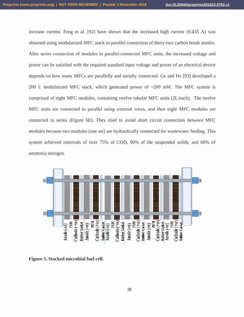
It is a type of configuration where fuel cells are stacked to form a battery of fuel cell.
This kind of construction does not affect each cell’s distinct Coulombic efficiency, but together it
increases the output of the overall battery to be comparable to conventional power sources as
shown in Figure 5. These can be either stacked in series or stacked in parallel. Both have their
importance and are high in power efficiency and can be practically utilized as a power source.
Stack yields higher voltage and current by the series connection and parallel connection,
respectively; accordingly, the required voltage, current, and power in electronic devices can be
satisfied. MFC can be connected in series, and parallel circuits hence called stacked MFC.
Designing stacked MFC efficiently is a critical issue. The type of electrode, stack direction
Preprints (www.preprints.org) | NOT PEER-REVIEWED | Posted: 2 November 2018 doi:10.20944/preprints201810.0763.v1

23
(horizontal or vertical type), shape of the reactor, determination of connection methods, and
modulation should be considered.
4.4.1 Bipolar electrode stack
Initial MFC reactors for stacking consist of anode chamber, a bipolar electrode,
membrane, a cathode chamber, and end plates that were externally similar with proton exchange
membrane (PEM) fuel cell stack (Figure 6A). The bipolar electrode for fuel cell stack has several
advantages such as 1) minimizing resistive losses (good electrical contacts), 2) minimizing iR
losses in current collectors, and 3) ease of fabrication. Shin et al. [69] used five bipolar plates
stacked MFCs in series, resulted in total voltage equal to the sum of individual MFCs and no
electrical degradation in performance. The bipolar stacked MFC is composed of an H-beam
shape of bipolar graphite that has two compartments at each side (anodic and cathodic
compartment), a Pt/C catalyst coated Nafion membrane at one side (positioned between each
bipolar plate), and end plates. The titanium (Ti) plate functioned as both anode and cathode can
also be used for MFC stack [70]. However, the bipolar stacked MFC in series has often observed
in voltage reversal [70-72], wherein the polarity of voltages of some MFCs among the stacked
MFC are suddenly reversed (from a positive value to a negative value), while the voltages of the
other MFCs still remain positive values. When the reversed MFCs operate for long-term, the
carbon corrosion makes the biofilm on the anode damage; therefore, the whole MFC system fails
[73]. This compact design of bipolar electrode would be difficult to separate and maintain
individually [71]. In addition, even if the bipolar electrode is separated from whole stacked MFC,
it cannot be guaranteed that the voltage reversal phenomenon will not appear in the other bipolar
stacked MFCs. An et al. [72] suggested membrane-less single-chambered MFC using a bipolar
Preprints (www.preprints.org) | NOT PEER-REVIEWED | Posted: 2 November 2018 doi:10.20944/preprints201810.0763.v1

24
plate-electrode assembly (BEA) that can easily be separated and stackable in series (Figure 6B).
An individual MFC unit was made of a cylindrical acrylic body, an anode (graphite felt) at the
bottom, a cathode (graphite felt) at the top, and a rigid graphite plate under the anode to protect
water leakage and air exposure. When two individual MFCs (MFC 1 unit and MFC 2 unit) are
stacked in series, for example, the anode in MFC 1 unit with the graphite plate directly connect
the cathode in MFC 2 unit without external wires. Whenever some MFCs show reversed polarity,
the MFCs using BEA can easily be detached, and then other MFCs can be connected. Though
the bipolar electrode distributes to reduce the internal resistance during series stack, shortcut
assembly and disassembly should be considered due to voltage reversal phenomenon. The stack
using external metal wires such as copper (Cu) and Ti wire would be a better choice for easy
connection of MFC units in series and in parallel rather than bipolar electrode stack.
4.4.2 Horizontal stack & vertical stack
The MFC can be stacked horizontally and vertically. Many researchers have used a
rectangular parallelepiped two-chamber MFC for the horizontal stack. Initial MFC stacks are
containing bipolar electrode MFC stack were also arranged in the horizontal direction [70, 71,
74]. Individual MFC unit for horizontal stack without bipolar electrode consists of anode and
cathode in the rectangular frames that have two ports (one for inlet and other for an outlet), and a
CEM or PEM between two frames (anode chamber and cathode chamber) [71, 75-79]. The MFC
units are horizontally stacked with each other by connecting electrically metal wires to current
collectors for making series or parallel circuits. The MFC units are also divided by rubber sheets
or acryl sheets for not sharing anolyte and/or catholyte from other MFC units. All the MFC units
with end plates and the sheets for separation of each MFC units are strongly tightened via several
Preprints (www.preprints.org) | NOT PEER-REVIEWED | Posted: 2 November 2018 doi:10.20944/preprints201810.0763.v1

25
long screws, such called horizontal MFC stack. Aelterman et al. [71] reported a maximum power
density of 308 W m-3 for series connection and 263 W m-3 for parallel connection based on the
polarization curves using horizontal stacked MFC system consisting six individual MFC units.
Recently, similar shape for pilot-scale horizontal MFC stack has been constructed and then
operated. Wu et al. showed that the maximum power density of 51 W m-3 and a COD removal
efficiency of 97% were achieved using the scaled-up stacked MFC in parallel connection (total
volume of 72 L) [75]. Vilajeliu-Pons et al. [76] presented the power density of between 2-4 W m-
3 using a couple of six stacked MFC in a combination of series and parallel connection from
swine manure as a substrate for more than six months. The total volume of the six stacked MFC
was 115 L.
The tubular air-cathode MFC design has also been used for the horizontal stack. Zhuang
and Zhou reported the tubular air-cathode MFC stack horizontally [80]. The tubular MFC unit
(void volume of 0.75 L) is constructed with polyvinyl chloride (PCV) plastic tube serving as the
frame of anode chamber and tubular membrane cathode assembly by hot-pressing carbon fiber
cloth to CEM. The substrate hydraulically flows between anode chambers. They used Ti wires to
serially connect each cell. This design could be adaptable for a drain pipe in the wastewater
treatment processes, have continuous plug flow. Zhuang et al. [81] constructed 10-liter
serpentine-type MFC stack using forty tubular air-cathode MFC units and then operated it for
180 days (Figure 6C). The OCV of 23.0 V and maximum power density of 4.1 W m-3 were
obtained from brewery wastewater by the series stack. They concluded that the serpentine-type
air-cathode MFC stack has the potential for application in wastewater treatment process due to
reduced capital costs, easy modulation, high scalability, and a simple wastewater distribution
system. However, each MFC unit would have different electrical performances due to different
Preprints (www.preprints.org) | NOT PEER-REVIEWED | Posted: 2 November 2018 doi:10.20944/preprints201810.0763.v1

26
concentration of organic matter and ion conductivity faced with biofilm on the anode in
continuous operation [82]. The low COD concentration near end MFC unit can reduce electrical
performances or even produce negligible power compared to the initial MFC near inlet. In long-
term operation, organic matter depletion near end MFC would result in extreme power loss and
then may fail to operation due to inactivate microorganisms in the biofilm. Also, when multiple
MFC units are connected in series, the voltage reversal could occur due to imbalance of substrate
loading, causing a kinetic imbalance between MFC units or between anode and cathode [83-85].
The vertical cascade stacked MFC system (Figure 6D) can also be confronted with the
voltage reversal phenomenon because of the substrate imbalances. However, the cascade stacked
MFC can be used as inexpensive way because the fluid flow of electrolytes was mostly gravity
driven without pumps. The horizontally stacked MFC system usually require extra pumps for
supplying substrate, e.g., wastewater, for microbes metabolism to anode chamber and oxidized
catholyte, i.e., air-saturated solution, for reduction reaction to the cathode chamber. It has been
reported that the first self-sustainable MFC stack capable of self-maintenance using vertical
cascade single-chamber MFC stacks consisting of 40 identical 20mL units (total volume of 0.8
L) [86]. Feeding, hydration, sensing, and reporting were performed by using the power from
MFC stack, and even the MFC stack produced extra energy, demonstrating net energy excess.
Also, the researchers achieved a COD removal of over 95% from artificial wastewater
(containing 5 mM acetate) during 5.7 h using six continuous-flow cascades MFCs by connection
in parallel [87]. Recently, the smartphone was successfully charged by scaled-up cascade MFC
stack (10.5 L of whole stack volume) employing urine as substrate [88]though the MFC stack
produced a low power of near 110 mW (maximum power density of ~10 W m-3). The phone call
was allowed for 1 h 45 min after 3 h of charge using the MFC stack. However, still, the methods
Preprints (www.preprints.org) | NOT PEER-REVIEWED | Posted: 2 November 2018 doi:10.20944/preprints201810.0763.v1

27
for maintaining flow rate, reduced organic concentration near end MFC, the volume of the
reactor, and height of the whole system would be considered for vertical cascade MFC stack to
maintain electrical and biological performances (i.e., power generation and wastewater
treatment) of MFC stack.
4.4.3 Modularized multiple electrodes MFC stack
The electrolyte has been not shared from other electrolytes by rubber sheets [71], bipolar
plate [70, 72, 74], thin inter-connecting tubes [81], and overflow [89] to prevent ionic cross-
conduction, causing voltage reversal of stacked MFC in series connection. The ionic cross-
conduction occurs when the same electrolyte (anolyte or catholyte) is shared by different MFC in
series connection [80]. These designs for separation of individual MFC reactors would require
additional materials, leading to the complex structure of reactor and increase of capital costs for
construction and maintenance. Modulation of MFC stack would be an efficient way to construct
a stacked MFC system simply and reduce construction costs. He et al. [90] developed the
stackable MFC with the anode and dual-cathode modules for simple construction, easy access,
and maintenance of the electrodes. The highest power density (11.0 W m-3) was achieved using
raw domestic wastewater with the MFC module. After that, a larger MFC module (6.1 L) using
four anode modules and three cathode modules were constructed and then operated, resulting in
the maximum power density of 6.0 W m-3 and COD removal of between 40-60% [91], but the
researchers were not conducted to stack operation by electrical series and parallel connection. A
promising development direction for the modularized MFC stack is to combine electrical arrays
with series connection and parallel connection of MFC units and/or MFC module. The MFC
units in a module are connected in parallel first to be capable to prevent voltage reversal and
Preprints (www.preprints.org) | NOT PEER-REVIEWED | Posted: 2 November 2018 doi:10.20944/preprints201810.0763.v1
28
increase current. Feng et al. [92] have shown that the increased high current (0.435 A) was
obtained using modularized MFC stack in parallel connection of thirty-two carbon brush anodes.
After series connection of modules in parallel-connected MFC units, the increased voltage and
power can be satisfied with the required standard input voltage and power of an electrical device
depends on how many MFCs are parallelly and serially connected. Ge and He [93] developed a
200 L modularized MFC stack, which generated power of ~200 mW. The MFC system is
comprised of eight MFC modules, containing twelve tubular MFC units (2L/each). The twelve
MFC units are connected in parallel using external wires, and then eight MFC modules are
connected in series (Figure 6E). They tried to avoid short circuit connection between MFC
modules because two modules (one set) are hydraulically connected for wastewater feeding. This
system achieved removals of over 75% of COD, 90% of the suspended solids, and 68% of
ammonia nitrogen.
Figure 5. Stacked microbial fuel cell.
Preprints (www.preprints.org) | NOT PEER-REVIEWED | Posted: 2 November 2018 doi:10.20944/preprints201810.0763.v1

29
Figure 6. The schematic diagrams of stacked MFCs configuration. A. a bipolar plate
two-chamber MFC horizontal stack; B. a tubular bipolar plate membrane-less two-
chamber MFC vertical stack; C. a tubular air-cathode MFC horizontal stack; D. a
cascade air-cathode MFC vertical stack; E. the module MFC stack in combination of
series and parallel connection.
Preprints (www.preprints.org) | NOT PEER-REVIEWED | Posted: 2 November 2018 doi:10.20944/preprints201810.0763.v1

30
Table 3. Summary of configuration, operational condition, and performance of MFC stack reported in literatures.
1) (s): series connection, 2) (p): parallel connection, 3) (s-p): series and parallel connection, 4) G-F-S: glucose-fructose-sucrose, 5) : Carbon brushes of
the number of 32 were parallel connected in a MFC.
Configuration Reactor
No.
Total
volum
e (L)
Electrode Connection Internal
resistance (Ω)
OCV
(V)
Maximum
power density
(W m-3)
Maximum
current density
(A m-3)
Organic conc.
or OLR Ref.
Two-chamber MFC
stack 6 0.936
Graphite
granules Cu wire 6.5 (s)1)
4.16 (s)
0.67 (p)
308 (s)
263 (p) 2)
0.085 A (s)
0.425 A (p) 1.62 g COD L-1 d-1 [56]
Bipolar two-
chamber MFC stack 4 20 Ti plates Ti plates 1.2 mΩ m-3 (s) 4.06 (s) 144 (s) 2.8 A m-2 - [94]
Two-chamber MFC
stack 3 1.8 Graphite Cu wire
11.5 Ω m-2 (s)
1 Ω m-2 (p)
1.042
(s)
0.687
(p)
0.11 W m-2 (s)
0.13 W m-2 (p)
0.098 A m-2 (s)
0.381 A m-2 (p) 30 g L-1 of G-F-S4) [95]
Two chamber MFC
stack 4 - Carbon cloth - -
3.27 (s)
0.82 (p)
2.22 W m-2 (s)
1.98 W m-2 (p)
16.9 A m-2 (s)
4.45 A m-2 (p) 0.5 g COD L-1 [96]
Single-chamber
MFC stack 10 0.063
Carbon fibre
veil - - 3.6 (s) 0.97 (p) ~7.1 (p) 5 mM of acetate [97]
Tubular type of
single-chamber
MFC stack
5 1.475
A: Graphite
felt
C: Carbon
fiber cloth
Ti wire 10-15 (p) 2.1 (s)
67.5 W m-2 (s)
175.7 W m-2
(p)
0.128 A m-2 (s)
0.675 A m-2 (p) 4.9 g COD L-1 d-1 [98]
Tubular type of
single-chamber
MFC stack
40 10
A; Graphite
felt
C: Metal
catalyst
Ti wire 800 (s)
15 (s-p) 3)
23 (s)
3.25 (s-
p)
4.1 (s)
6.0 (s-p)
2.1 (s)
13.8 (s-p) 1.06 g COD L-1 d-1 [99]
Cascade type of
single-chamber 3D-
printed MFC stack
40 0.8 Carbon veil - -
13 (20
units
used)
- - 25 mM of acetate [100]
Horizontally
stackable type of
single-chamber
MFC
1 (32) 5) 250
A: Carbon
brush
C: Carbon
mesh
Ti wire 2.3×10⁸ Ω m-2 0.8 (p) 0.116 W 0.435 A ~0.32 g COD L-1 [101]
Bipolar plate single-
chamber MFC stack 3 0.35 Graphite felt
Graphite
plate 634 1.58 (s)
0.023 W m-2
(s) 0.037 A m-2 10 mM of acetate [102]
Preprints (www.preprints.org) | NOT PEER-REVIEWED | Posted: 2 November 2018 doi:10.20944/preprints201810.0763.v1

31
5. Scalability of MFC
Compared to other renewable energy sources, MFC is still considered as a low energy
producing system because of its thermodynamic limitations and different voltage losses
associated with redox reactions. The theoretical maximum voltage that could be achieved from
the best MFC configurations mentioned so far is about 1V using acetate as a carbon source in
anodic chamber and oxygen as the cathodic electron acceptor [103]. Still, the actual voltage
obtained from an MFC is always lower than the theoretical maximum voltage due to several
voltage losses, often called as overpotential losses [14, 103]. The major problems restricts the
application of this technique from commercialization is the technology application (restricted by
design aspects, and technological, electrochemical and microbiological limitations), cathodic
electron transfer limitation, slower Coulombic efficiency (CE), lower power production and high
capital cost compared to other conventional wastewater treatment processes [104]. Although
improvement in power and the current density was reported from the scalable design of MFC,
this increase in electrical output is disproportional with the corresponding increase in anodic
chamber volume [105]. Microbes are relatively slow electron transformers even at its fastest
growth rate and have to compete with other non-electrogens for food as in case of mixed
inoculum. Another limitation is represented by substrate diffusion towards anode in anodic
chamber of larger volume MFC, which is not at sufficient rate to reach acceptable levels of
current and cell potential (to minimize the diffusion losses) and it needs proper mixing condition
for better proton transfer and to maintain homogenous condition throughout the electrolyte
solution [106].
Preprints (www.preprints.org) | NOT PEER-REVIEWED | Posted: 2 November 2018 doi:10.20944/preprints201810.0763.v1
32
Before thinking of commercial manufacturing, bioreactor and the processes within are
required to scale-up. This involves many steps of volume increase in bioreactors. Proportional
volumetric power generation decreased with increase in the volume of MFC. The MFCs real
applications scalability is decisive, concerning not only increased fuel utilization efficiency and
capacity, but also concerning increasing electricity power generation. Hence, this concept has
always been a critical issue that affects their practical applications. Scale-up of MFCs from the
laboratory to pilot scale is a challenging step in the development of the process. The challenges
for bringing MFC technologies for practical applications underlying the fact the factors that
might influence the MFC performance have to be considered. The primary challenge is scaling
the energy production along with reactor liquid volume. Total power generation can be improved
either by increasing the reactor volume or by electrically connecting some MFCs in series or
parallel. Nonetheless, any scale-up work made from the bench-scale bioreactor of one to
thousand liters of volume is not an easy task [107-109]. Therefore, it is challenging when one
considers all the added difficulty in operational complexity, logistic supports, utility supplies,
regulatory and safety compliance besides already broad technical issues have to be addressed.
With the limited information and knowledge available, the researcher must integrate many
different approaches and tailor them to the specific or general situation.
For MFC system better optimization and to improve its efficiency, different aspects have
to be considered. These include inoculums, the substrate (fuel), proton exchange membrane
material, fuel cell internal and external resistance, the ionic strength of the solution, electrode
materials, and electrode spacing [110]. In addition, interesting factors that could influence the
overall performance of the system such as mode of operation [111], effects of gravity and
Preprints (www.preprints.org) | NOT PEER-REVIEWED | Posted: 2 November 2018 doi:10.20944/preprints201810.0763.v1
33
geometric flow [112], effect of culture time [113, 114], and chaotic application for stimulation of
microbial activity [115] have to be considered.
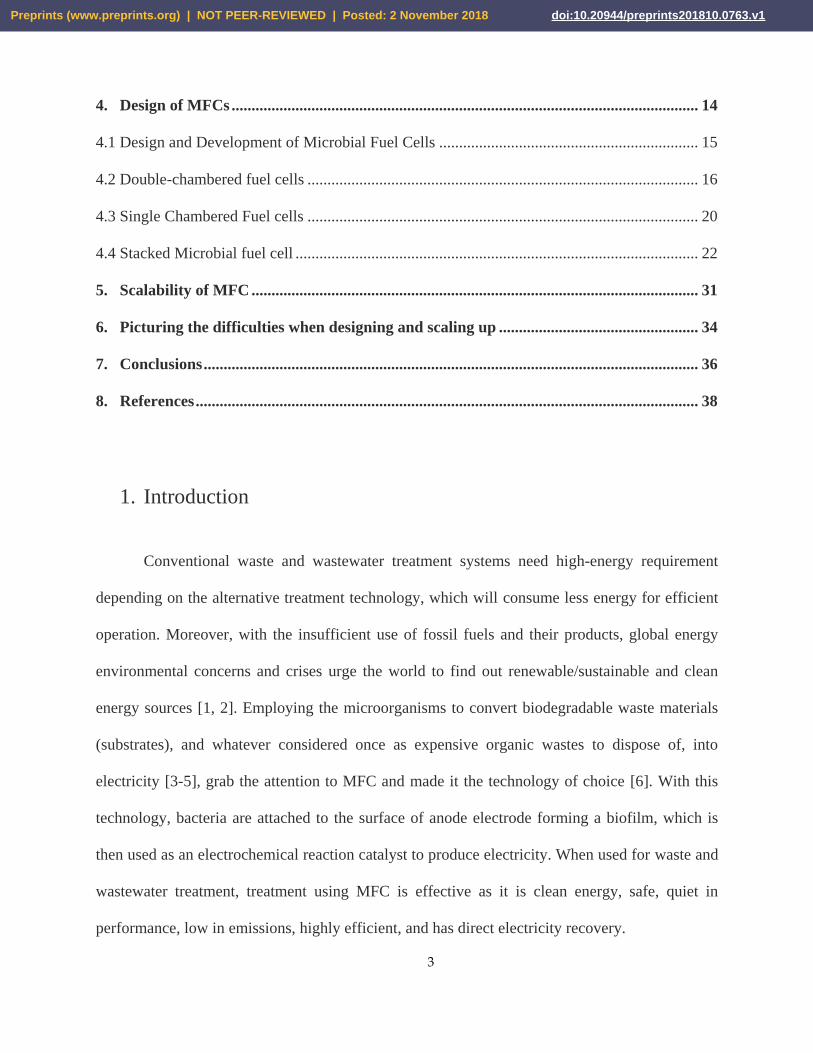
Finally yet importantly, based on internet news posts, conference presentations, and
researchers discussion forums, there are very few large-scale tests of microbial fuel cells. The
largest of all was conducted at Foster's brewery in Yatala, Queensland (Australia), by the
Advanced Water Management Center at the University of Queensland. The reactor consisted of
12 modules, each 3 m high, with a total volume of approximately 1 m3 (Figure 7). The reactor
contained carbon fiber brush anodes inside tubular reactors covered with graphite fiber brush
cathodes, with flow up through the tubes and out over the outside of the reactor. This design was
similar to one tested in the laboratory with a ferricyanide catholyte [116]. Little is known about
MFC performance at the site, other than solution conductivity was low, limiting current
generation, and that excess biochemical oxygen demand in the wastewater leaving the anode
chamber resulted in the build-up of excessive biofilm on the cathodes as the wastewater was
exposed to air.
Preprints (www.preprints.org) | NOT PEER-REVIEWED | Posted: 2 November 2018 doi:10.20944/preprints201810.0763.v1

34
Figure 7: Brewery in Yatala, Queensland (Australia) at the University of Queensland,
conducted a large scale MFC under the direction of Jurg Keller and Korneel Rabaey
(www.microbialfuelcell.org).
6. Picturing the difficulties when designing and scaling up
When we think of the designing and its importance to solve the problem of MFC, we
have to picture the process and what calculations and planning steps involved to constructing a
building and try to do the same when designing the MFC reactors. Either it is of one floor or
hundred-floor building, it does not matter because both will have the same process and same
steps with different volumes and proportions but what matters is the perfect design to serve the
cause with whatever budget available.
Preprints (www.preprints.org) | NOT PEER-REVIEWED | Posted: 2 November 2018 doi:10.20944/preprints201810.0763.v1

35
The first step in the plan to construct a ten-floor building is to plan everything on paper
from the foundation to the tenth floor and have your blueprint ready for that. Drawing a blueprint
and make it ready is not an easy task because it involves planning for the general and specific
details of the building depending on the cause. Whoever preparing the blue print should ask
themselves many questions, and the answers should be clear before they start sketching how the
building will look like. The first big question should be what is the cause of this building? Is this
building for personal use or public use? Is it for individuals or the government? Is it like a
shopping mall and hospitals with different entrances and exits leading to different parking lots or
it is like a private or company building with one or two entrance and one or two exits leading to
one reasonably big parking lot? and so on. Answers to these questions will lead to the next step
in the designing and drawing of the blue print, which how much funding and space are available
to proceed and make this project to happen. Accordingly, the designer will start thinking about
what the design should look like and what are the materials should be used with whatever cost
included within the budget. At this point, the designer should have a broad and unstoppable
imagination about the interior and exterior design and what it should look like to serve the cause?
However, part of the process of designing is to make a prototype (small scale) of the design to
view what is going to be real and try to think of any pros and cons that this design might have
after consulting with other expertise. The prototype design would help the designer to think more
about some details and experimental testing what should go wrong with the design if this
prototype brought to scale up to face the real daily life problems.
Moreover, to perfictionize the process, one crucial issue should carefully be considered;
engineering mathematical calculations. Every single detail such the volume and ratio of cement
versus water, size of doors and hinges, electrical and plumbing layouts, health measures against
Preprints (www.preprints.org) | NOT PEER-REVIEWED | Posted: 2 November 2018 doi:10.20944/preprints201810.0763.v1
36
rodents and insects, and safety measures in case of fire should be calculated and considered.
Nevertheless, any issue that we might think it is insignificant should not be ignored or
underestimated as it might help to serve the case, but sometimes we need to dig in little more to
be able to picture the real problem and find a solution for it.
7. Conclusions
For the microbial fuel cells to function appropriately with the highest production and
efficiency possible, all the elements involved in the reaction have to be considered. A better
understanding of these elements, how they function, what factors that could affect them, and the
impact of these factors is the key part of the puzzle or what and this impact is it due to multiple
or due to one individual effect. Therefore, more and better understanding of the system and its
components will be useful in controlling the power efficiency and the type of energy produced.
The development of MFC technology needs a selection of suitable and cost-effective
electrode materials and separator, and engineering design of scalable architecture to find its
feasibility for wastewater treatment under optimum operating conditions.
Unfortunately, with the current publications, no one ever has the accurate study that
integrated various science and engineering scale-up approaches and applied them correctly to the
industrial situations with a case study as a demonstration.
Furthermore, compared to what researchers have started with, the amount of progress
made to date is impressive with the small amount of funding available in this field of research.
Many companies are now looking into commercialization of these systems with promising future.
Preprints (www.preprints.org) | NOT PEER-REVIEWED | Posted: 2 November 2018 doi:10.20944/preprints201810.0763.v1

37
It is hoped that with more funding and continuous progress in research using cost-effective
materials and designs, such systems could be soon commercially available.
Moreover, if researchers start to think using the strategy recommended in this review,
there should not be any problem in scaling up or even scaling down. As per group opinion, the
key point why most researchers somehow failed to scale up their successful experiments using
whatever reactor design, because they do not fully understand not only the engineering
mathematics behind scaling up but also other fields. Therefore, it is recommended to collaborate
as a team with a variety of expertise in different fields like architecture engineering, civil
engineering, environmental, artists and designers, electrochemical engineering, materials science,
electrical and electronic engineering, fluid and thermodynamics, biology and microbiology,
environmental science, and so on.
Acknowledgments
This research project was supported by Korea Ministry of Environment (The SEM project:
2018002450001).
Preprints (www.preprints.org) | NOT PEER-REVIEWED | Posted: 2 November 2018 doi:10.20944/preprints201810.0763.v1

38
8. References
[1] Bishoge O, Zhang L, Mushi W. The Potential Renewable Energy for Sustainable
Development in Tanzania: A Review. Clean Technologies 2018;1:6.
[2] Owusu PA, Asumadu-Sarkodie S. A review of renewable energy sources, sustainability
issues and climate change mitigation. Cogent Engineering 2016;3.
[3] Allen R, Bennetto HP. Microbial fuel-cells. Applied Biochemistry and Biotechnology
1993;39-40:27.
[4] Bond DR, Lovley DR. Electricity Production by Geobacter sulfurreducens Attached to
Electrodes. Applied and Environmental Microbiology 2003;69:1548.
[5] Kim HJ, Park HS, Hyun MS, Chang IS, Kim M, Kim BH. A mediator-less microbial fuel
cell using a metal reducing bacterium, Shewanella putrefaciens. Enzyme and Microbial
Technology 2002;30:145.
[6] Bose D, Kandpal V, Dhawan H, Vijay P, Gopinath M. Energy Recovery with Microbial
Fuel Cells: Bioremediation and Bioelectricity. In: Varjani SJ, Gnansounou E, Gurunathan B,
Pant D, Zakaria ZA, editors. Waste Bioremediation. Singapore: Springer Singapore; 2018, p. 7.
[7] Potter MC. Electrical effects accompanying the decomposition of organic compounds.
Proceedings of the Royal Society of London Series B, Containing Papers of a Biological
Character 1911;84:260.
[8] Rohrback GH, Scott, W. R. and Canfield, J. H. Biochemical fuel cells. Biological
Fuel Cells and Their Applications: in Proceedings of the 16th Annual Power Sources Conference
1962;19:18.
[9] Williams KR. An Introduction to Fuel Cells. Elsevier, Amsterdam 1966.
[10] Yao SJ, Appleby, A. J., Geise, A., Cash, H. R. and Wolfson, S. K. Anodic oxidation of
carbohydrates and their derivatives in neutral saline solution. . Nature 1969;224:921.
[11] Karube I, Ikemoto, H., Kajiwara, K., Tamiya, E. and Matsuok, H. Photochemical
energy conversion using immobilized blue-green algae. J Biotechnol 1986;4:73.
[12] Allen RM, Bennetto HP. Microbial fuel-cells-electricity production from carbohydrates.
Applied Biochemistry and Biotechnology 1993;39:27.
[13] Chang IS, Moon H, Bretschger O, Jang JK, Park HI, Nealson KH, et al.
Electrochemically active bacteria (EAB) and mediator-less microbial fuel cells. Journal of
Microbiology and Biotechnology 2006;16:163.
Preprints (www.preprints.org) | NOT PEER-REVIEWED | Posted: 2 November 2018 doi:10.20944/preprints201810.0763.v1

39
[14] Du Z, Li, H. and Gu, T. A state of the art review on microbial fuel cells: A promising
technology for wastewater treatment and bioenergy. Biotech Advances 2007;25 464.
[15] Logan BE, Hamelers B, Rozendal R, Schröder U, Keller J, Freguia S, et al. Microbial
Fuel Cells: Methodology and Technology†. Environmental Science & Technology
2006;40:5181.
[16] Watanabe K. Recent Developments in Microbial Fuel Cell Technologies for Sustainable
Bioenergy. Journal of Bioscience and Bioengineering 2008;106:528.
[17] Katz E, Shipway AN, Willner I. Biochemical fuel cells. Handbook of Fuel Cells: John
Wiley & Sons, Ltd; 2010.
[18] Allen RMaB, H.P.,. Microbial Fuel Cells—Electricity Production from Carbohydrates.
Appl Biochem Biotechnol 1993;39/40:27.
[19] Borole A, Reguera, G., Ringeisen, B., Wang, ZW., Feng, Y., and Kim, BH. Electroactive
biofilms: current status and future research needs. Energy Environ Sci 2011;4:4813.
[20] Kumar R, Singh, L., Wahid, ZA., and Fadhil, M. Exoelectrogens in microbial fuel cells
towards bioelectricity generation: a review. Int Journal Energy Res 2015;39:1048.
[21] Hamelers HM, Ter Heijne A, Sleutels TJA, Jeremiasse A, Strik DBTB, Buisman CN.
New applications and performance of bioelectrochemical systems. Applied Microbiology and
Biotechnology 2010;85:1673.
[22] Zhao F, Harnisch F, Schroder U, Scholz F, Bogdanoff P, Herrmann I. Application of
pyrolysed iron(II) phthalocyanine and CoTMPP based oxygen reduction catalysts as cathode
materials in microbial fuel cells. Electrochemistry Communications 2005;7:1405.
[23] Cheng S, Liu H, Logan BE. Power Densities Using Different Cathode Catalysts (Pt and
CoTMPP) and Polymer Binders (Nafion and PTFE) in Single Chamber Microbial Fuel Cells.
Environmental Science & Technology 2006;40:364.
[24] Chen T, Barton SC, Binyamin G, Gao Z, Zhang Y, Kim H-H, et al. A Miniature Biofuel
Cell. Journal of the American Chemical Society 2001;123:8630.
[25] Habermann W, Pommer EH. Biological fuel cells with sulphide storage capacity. Applied
Microbiology and Biotechnology 1991;35:128.
[26] Kim JR, Jung SH, Regan JM, Logan BE. Electricity generation and microbial community
analysis of alcohol powered microbial fuel cells. Bioresource Technology 2007;98:2568.
[27] Catal T, Xu S, Li K, Bermek H, Liu H. Electricity generation from polyalcohols in
single-chamber microbial fuel cells. Biosensors and Bioelectronics 2008;24:849.
Preprints (www.preprints.org) | NOT PEER-REVIEWED | Posted: 2 November 2018 doi:10.20944/preprints201810.0763.v1

40
[28] Liu Y, Dong S. A biofuel cell with enhanced power output by grape juice.
Electrochemistry Communications 2007;9:1423.
[29] Velasquez-Orta SB, Head IM, Curtis TP, Scott K. Factors affecting current production in
microbial fuel cells using different industrial wastewaters. Bioresource Technology
2011;102:5105.
[30] Gil G-C, Chang I-S, Kim BH, Kim M, Jang J-K, Park HS, et al. Operational parameters
affecting the performannce of a mediator-less microbial fuel cell. Biosensors and Bioelectronics
2003;18:327.
[31] Lu N, Zhou S-g, Zhuang L, Zhang J-t, Ni J-r. Electricity generation from starch
processing wastewater using microbial fuel cell technology. Biochemical Engineering Journal
2009;43:246.
[32] Patil SA, Surakasi VP, Koul S, Ijmulwar S, Vivek A, Shouche YS, et al. Electricity
generation using chocolate industry wastewater and its treatment in activated sludge based
microbial fuel cell and analysis of developed microbial community in the anode chamber.
Bioresource Technology 2009;100:5132.
[33] Oh S, Logan BE. Hydrogen and electricity production from a food processing wastewater
using fermentation and microbial fuel cell technologies. Water Research 2005;39:4673.
[34] Wen Q, Wu Y, Cao D, Zhao L, Sun Q. Electricity generation and modeling of microbial
fuel cell from continuous beer brewery wastewater. Bioresource Technology 2009;100:4171.
[35] Jiang J, Zhao Q, Zhang J, Zhang G, Lee D-J. Electricity generation from bio-treatment of
sewage sludge with microbial fuel cell. Bioresource Technology 2009;100:5808.
[36] Cercado-Quezada B, Delia M-L, Bergel A. Testing various food-industry wastes for
electricity production in microbial fuel cell. Bioresource Technology 2010;101:2748.
[37] Park DH, Zeikus JG. Electricity Generation in Microbial Fuel Cells Using Neutral Red as
an Electronophore. Applied and Environmental Microbiology 2000;66:1292.
[38] Ieropoulos IA, Greenman J, Melhuish C, Hart J. Comparative study of three types of
microbial fuel cell. Enzyme and Microbial Technology 2005;37:238.
[39] Bennetto HP, Stirling JL, Tanaka K, Vega CA. Anodic reactions in microbial fuel cells.
Biotechnology and Bioengineering 1983;25:559.
[40] Ringeisen BR, Henderson E, Wu PK, Pietron J, Ray R, Little B, et al. High Power
Density from a Miniature Microbial Fuel Cell Using Shewanella oneidensis DSP10.
Environmental Science & Technology 2006;40:2629.
Preprints (www.preprints.org) | NOT PEER-REVIEWED | Posted: 2 November 2018 doi:10.20944/preprints201810.0763.v1
41
[41] Kim B, Ikeda T, Park H, Kim H, Hyun M, Kano K, et al. Electrochemical activity of an
Fe(III)-reducing bacterium, Shewanella putrefaciens IR-1, in the presence of alternative electron
acceptors. Biotechnology Techniques 1999;13:475.
[42] Chaudhuri SK, Lovley DR. Electricity generation by direct oxidation of glucose in
mediatorless microbial fuel cells. Nat Biotech 2003;21:1229.
[43] Shantaram A, Beyenal H, Veluchamy RRA, Lewandowski Z. Wireless Sensors Powered
by Microbial Fuel Cells. Environmental Science & Technology 2005;39:5037.
[44] Rabaey K, Verstraete W. Microbial fuel cells: novel biotechnology for energy generation.
Trends in Biotechnology 2005;23:291.
[45] Chaudhuri SK, Lovley DR. Electricity generation by direct oxidation of glucose in
mediatorless microbial fuel cells. Nature Biotechnology 2003;21:1229.
[46] Pham CA, Jung SJ, Phung NT, Lee J, Chang IS, Kim BH, et al. A novel
electrochemically active and Fe(III)-reducing bacterium phylogenetically related to Aeromonas
hydrophila, isolated from a microbial fuel cell. FEMS Microbiology Letters 2003;223:129.
[47] Zhang L, Zhou S, Zhuang L, Li W, Zhang J, Lu N, et al. Microbial fuel cell based on
Klebsiella pneumoniae biofilm. Electrochemistry Communications 2008;10:1641.
[48] Flimban SGA, Hassan SHA, Rahman MM, Oh S-E. The effect of Nafion membrane
fouling on the power generation of a microbial fuel cell. International Journal of Hydrogen
Energy 2018.
[49] Kondaveeti S, Lee, J., Kakarla, R., Kim, H. S., & Min, B. Low-cost separators for
enhanced power production and field application of MFCs (MFCs). Electrochimica Acta
2014;132:434.
[50] Call D, Logan BE. Hydrogen Production in a Single Chamber Microbial Electrolysis Cell
Lacking a Membrane. Environmental Science & Technology 2008;42:3401.
[51] Pant D, Bogaert, G. V., Diels, L. and Vanbroekhoven, K. A review of the substrates used
in microbial fuel cells (MFCs) for sustainable energy production. Biores Technol 2010;101 1533.
[52] Logan B, Cheng S, Watson V, Estadt G. Graphite Fiber Brush Anodes for Increased
Power Production in Air-Cathode Microbial Fuel Cells. Environmental Science & Technology
2007;41:3341.
[53] Liu H, Cheng S, Logan BE. Power Generation in Fed-Batch Microbial Fuel Cells as a
Function of Ionic Strength, Temperature, and Reactor Configuration. Environmental Science &
Technology 2005a;39:5488.
Preprints (www.preprints.org) | NOT PEER-REVIEWED | Posted: 2 November 2018 doi:10.20944/preprints201810.0763.v1
42
[54] You S, Zhao Q, Zhang J, Jiang J, Zhao S. A microbial fuel cell using permanganate as the
cathodic electron acceptor. Journal of Power Sources 2006;162:1409.
[55] Rabaey K, Boon N, Siciliano SD, Verhaege M, Verstraete W. Biofuel Cells Select for
Microbial Consortia That Self-Mediate Electron Transfer. Applied and Environmental
Microbiology 2004;70:5373.
[56] Aelterman P, Rabaey K, Pham HT, Boon N, Verstraete W. Continuous Electricity
Generation at High Voltages and Currents Using Stacked Microbial Fuel Cells. Environmental
Science & Technology 2006;40:3388.
[57] Tremouli A, Greenman J, Ieropoulos I. Investigation of ceramic MFC stacks for urine
energy extraction. Bioelectrochemistry 2018;123:19.
[58] Asensio Y, Montes IB, Fernandez-Marchante CM, Lobato J, Cañizares P, Rodrigo MA.
Selection of cheap electrodes for two-compartment microbial fuel cells. Journal of
Electroanalytical Chemistry 2017;785:235.
[59] Sun J, Hu, Y., Bi, Z., & Cao, Y. Improved performance of air-cathode single-chamber
MFC for wastewater treatment using microfiltration membranes and multiple sludge inoculation. .
Journal of Power Sources 2009;187:471.
[60] Choi S, Kim, J. R., Cha, J., Kim, Y., Premier, G. C., & Kim, C. Enhanced power
production of a membrane electrode assembly MFC (MFC) using a cost effective
poly[2,5-benzimidazole] (ABPBI) impregnated non-woven fabric filter. Bioresource Technology
2013;128:14.
[61] Min B, Logan BE. Continuous Electricity Generation from Domestic Wastewater and
Organic Substrates in a Flat Plate Microbial Fuel Cell. Environmental Science & Technology
2004;38:5809.
[62] Kim JR, Cheng, S., Oh, S.-E., & Logan, B. E. Power generation using different cation,
anion, and ultrafiltration membranes in MFCs. . Environmental Science & Technology
2007;41:1004.
[63] He Z, Minteer SD, Angenent LT. Electricity Generation from Artificial Wastewater
Using an Upflow Microbial Fuel Cell. Environmental Science & Technology 2005;39:5262.
[64] He Z, Wagner N, Minteer SD, Angenent LT. An Upflow Microbial Fuel Cell with an
Interior Cathode: Assessment of the Internal Resistance by Impedance Spectroscopy.
Environmental Science & Technology 2006;40:5212.
[65] Liu H, and Logan, Bruce E. Electricity Generation Using an Air-Cathode Single
Chamber Microbial Fuel Cell in the Presence and Absence of a Proton Exchange Membrane.
Environmental Science & Technology 2004;38:4040.
Preprints (www.preprints.org) | NOT PEER-REVIEWED | Posted: 2 November 2018 doi:10.20944/preprints201810.0763.v1

43
[66] Eom H, Chung, K., Kim, I., & Han, J.I. Development of a hybrid microbial fuel cell
(MFC) and fuel cell (FC) system for improved cathodic efficiency and sustainability: the
M2FC reactor. chemosphere 2011;85:672.
[67] Gottesfeld S, and Zawodzinski, T.A. Polymer electrolyte fuel cell. Adv. . Electrochem
Sci 1997;5:195.
[68] Cheng S, Liu, H., & Logan, B. E. Increased performance of single-chamber MFCs using
an improved cathode structure. Electrochemistry Communications 2006a;8:489.
[69] Shin S-H, Choi Y-j, Na S-H, Jung S-h, Kim S-h. Development of bipolar plate stack type
microbial fuel cells. Bulletin of the Korean Chemical Society 2006;27:281.
[70] Dekker AH, A. T.; Saakes, M.; Hamelers, H. V.; Buisman, C. J. Analysis and
improvement of a scaled-up and stacked microbial fuel cell. Environmental science &
technology 2009;43:9038.
[71] Aelterman PR, K.; Pham, H. T.; Boon, N.; Verstraete, W. Continuous electricity
generation at high voltages and currents using stacked microbial fuel cells. Environmental
science & technology 2006;40:3388.
[72] An JK, B.; Jang, J. K.; Lee, H.-S.; Chang, I. S. New architecture for modulization of
membraneless and single-chambered microbial fuel cell using a bipolar plate-electrode assembly
(BEA). Biosensors and Bioelectronics 2014;59:28.
[73] Li JL, H.; Fu, Q.; Liao, Q.; Zhu, X.; Kobayashi, H.; Ye, D. Voltage reversal causes
bioanode corrosion in microbial fuel cell stacks. International Journal of Hydrogen Energy 2017.
[74] Shin S-HC, Y.-j.; Na, S.-H.; Jung, S.-h.; Kim, S.-h. Development of bipolar plate stack
type microbial fuel cells. Bulletin of the Korean Chemical Society 2006;27:281.
[75] Wu SL, H.; Zhou, X.; Liang, P.; Zhang, X.; Jiang, Y.; Huang, X. A novel pilot-scale
stacked microbial fuel cell for efficient electricity generation and wastewater treatment. Water
Research 2016;98:396.
[76] Vilajeliu-Pons AP, S.; Salcedo-Dávila, I.; Balaguer, M.; Colprim, J. Long-term
assessment of six-stacked scaled-up MFCs treating swine manure with different electrode
materials. Environmental Science: Water Research & Technology 2017;3:947.
[77] Rahimnejad MG, A.; Najafpour, G.; Younesi, H.; Shakeri, M. A novel microbial fuel cell
stack for continuous production of clean energy. International Journal of Hydrogen Energy
2012;37:5992.
[78] Jafary TR, M.; Ghoreyshi, A. A.; Najafpour, G.; Hghparast, F.; Daud, W. R. W.
Assessment of bioelectricity production in microbial fuel cells through series and parallel
connections. Energy conversion and management 2013;75:256.
Preprints (www.preprints.org) | NOT PEER-REVIEWED | Posted: 2 November 2018 doi:10.20944/preprints201810.0763.v1

44
[79] Zhang LL, J.; Zhu, X.; Ye, D.-d.; Fu, Q.; Liao, Q. Response of stacked microbial fuel
cells with serpentine flow fields to variable operating conditions. International Journal of
Hydrogen Energy 2017;42:27641.
[80] Zhuang LZ, S. Substrate cross-conduction effect on the performance of serially
connected microbial fuel cell stack. Electrochemistry communications 2009;11:937.
[81] Zhuang LY, Y.; Wang, Y.; Zhou, S. Long-term evaluation of a 10-liter serpentine-type
microbial fuel cell stack treating brewery wastewater. Bioresource Technology 2012;123:406.
[82] Gurung AK, J.; Jung, S.; Jeon, B.-H.; Yang, J. E.; Oh, S.-E. Effects of substrate
concentrations on performance of serially connected microbial fuel cells (MFCs) operated in a
continuous mode. Biotechnology Letters 2012;34:1833.
[83] Oh S-EL, B. E. Voltage reversal during microbial fuel cell stack operation. Journal of
Power Sources 2007;167:11.
[84] An JL, H. S. Occurrence and Implications of Voltage Reversal in Stacked Microbial Fuel
Cells. ChemSusChem 2014;7:1689.
[85] An JS, J.; Lee, H.-S. Control of voltage reversal in serially stacked microbial fuel cells
through manipulating current: Significance of critical current density. Journal of Power Sources
2015;283:19.
[86] Ledezma PS, A.; Greenman, J.; Ieropoulos, I. The first self-sustainable microbial fuel cell
stack. Physical chemistry chemical physics : PCCP 2013;15:2278.
[87] Ledezma PG, J.; Ieropoulos, I. MFC-cascade stacks maximise COD reduction and avoid
voltage reversal under adverse conditions. Bioresource Technology 2013;134:158.
[88] Walter XAS, A.; Greenman, J.; Ieropoulos, I. Urine transduction to usable energy: a
modular MFC approach for smartphone and remote system charging. Applied Energy
2017;192:575.
[89] Tremouli AG, J.; Ieropoulos, I. Investigation of ceramic MFC stacks for urine energy
extraction. Bioelectrochemistry 2018;123:19.
[90] He WZ, X.; Liu, J.; Zhu, X.; Feng, Y.; Logan, B. E. Microbial fuel cells with an
integrated spacer and separate anode and cathode modules. Environmental Science: Water
Research & Technology 2016;2:186.
[91] He WW, M. J.; Kim, K.-Y.; Zhang, X.; Yang, W.; Zhu, X.; Feng, Y.; Logan, B. E. The
effect of flow modes and electrode combinations on the performance of a multiple module
microbial fuel cell installed at wastewater treatment plant. Water Research 2016;105:351.
Preprints (www.preprints.org) | NOT PEER-REVIEWED | Posted: 2 November 2018 doi:10.20944/preprints201810.0763.v1
45
[92] Feng YH, W.; Liu, J.; Wang, X.; Qu, Y.; Ren, N., A. horizontal plug flow and stackable
pilot microbial fuel cell for municipal wastewater treatment. Bioresource Technology
2014;156:132.
[93] Ge ZH, Zhen. Long-term performance of a 200 liter modularized microbial fuel cell
system treating municipal wastewater: treatment, energy, and cost. Environmental Science:
Water Research & Technology 2016;2:274.
[94] Dekker A, Heijne AT, Saakes M, Hamelers HV, Buisman CJ. Analysis and improvement
of a scaled-up and stacked microbial fuel cell. Environmental science & technology
2009;43:9038.
[95] Jafary T, Rahimnejad M, Ghoreyshi AA, Najafpour G, Hghparast F, Daud WRW.
Assessment of bioelectricity production in microbial fuel cells through series and parallel
connections. Energy conversion and management 2013;75:256.
[96] Zhang L, Li J, Zhu X, Ye D-d, Fu Q, Liao Q. Response of stacked microbial fuel cells
with serpentine flow fields to variable operating conditions. International Journal of Hydrogen
Energy 2017;42:27641.
[97] Ieropoulos I, Greenman J, Melhuish C. Microbial fuel cells based on carbon veil
electrodes: stack configuration and scalability. International Journal of Energy Research
2008;32:1228.
[98] Zhuang L, Zheng Y, Zhou S, Yuan Y, Yuan H, Chen Y. Scalable microbial fuel cell
(MFC) stack for continuous real wastewater treatment. Bioresource Technology 2012;106:82.
[99] Zhuang L, Yuan Y, Wang Y, Zhou S. Long-term evaluation of a 10-liter serpentine-type
microbial fuel cell stack treating brewery wastewater. Bioresource Technology 2012;123:406.
[100] Ledezma P, Stinchcombe A, Greenman J, Ieropoulos I. The first self-sustainable
microbial fuel cell stack. Physical chemistry chemical physics : PCCP 2013;15:2278.
[101] Feng Y, He W, Liu J, Wang X, Qu Y, Ren N. A horizontal plug flow and stackable pilot
microbial fuel cell for municipal wastewater treatment. Bioresource Technology 2014;156:132.
[102] An J, Kim B, Jang JK, Lee H-S, Chang IS. New architecture for modulization of
membraneless and single-chambered microbial fuel cell using a bipolar plate-electrode assembly
(BEA). Biosensors and Bioelectronics 2014;59:28.
[103] Logan BE. Microbial fuel cells. 2008.
[104] Jadhav DA, Ghadge, A. N., & Ghangrekar, M. M. Simultaneous organic matter removal
and disinfection of wastewater with enhanced power generation in microbial fuel cell. .
Bioresource Technology 2014;163:328.
Preprints (www.preprints.org) | NOT PEER-REVIEWED | Posted: 2 November 2018 doi:10.20944/preprints201810.0763.v1

46
[105] Feng Y, He, W., Liu, J., Wang, X., Qu, Y., & Ren, N. A horizontal plug flow & stackable
pilot microbial fuel cell for municipal wastewater treatment. Bioresource Technology
2014;156:132.
[106] Rabaey K, Lissens, G. & Verstraete, W. Microbial fuel cells: Performances and
perspectives. In: Piet Lens PW, Marianne Haberbauer and Angelo Moreno, editor. Biofuels for
fuel cells: Renewable energy from biomass fermentation. London, UK: IWA Publishing; 2012, p.
377.
[107] Janicek A, Fan, Y., & Liu, H. Design of microbial fuel cells for practical application: A
review and analysis of scale-up studies. Biofuels 2014;5:79.
[108] Logan B. Scaling up microbial fuel cells and other bioelectrochemical systems. Applied
Microbiology and Biotechnology 2010;85:1665.
[109] Ghadge AN, Jadhav, D. A., & Ghangrekar, M. M. Wastewater treatment in pilot-scale
microbial fuel cell using multi-electrode assembly with ceramic separator suitable for field
applications. Environmental Progress & Sustainable Energy 2016.
[110] Cheng S, H. Liu, and B. E. Logan. Increased performance of single-chamber
microbial fuel cells using an improved cathode structure. Electrochemistry Communications
2006;8 489.
[111] Surajbhan S, Dominguez-Benetton X, Graichen FHM, Vanbroekhoven K, Wever Hd,
Sreekrishnan TR, et al. Shift to continuous operation of an air-cathode microbial fuel cell long-
running in fed-batch mode boosts power generation. International Journal of Green Energy
2016;13:71.
[112] Lan T-H, C.-T. Wang, Y.-C. Yang, and C. Wen-Tong. Multieffects of gravity and
geometric flow channel on the performance of continuous microbial fuel cells. International
Journal of Green Energy 2016;13:1483.
[113] Tsan WC, C. W. Jung, and H. R. Yao. Effect of culture time on the growth curve and
power performance in microbial fuel cell at a fixed amount of liquid culture. International
Journal of Green Energy 2015;13:695.
[114] Sevda S, X. Dominguez-Benetton, F. H. M. Graichen, K. Vanbroekhoven, H. de Wever,
T. R. Sreekrishnan, and D. Pant. Shift to continuous operation of an air-cathode microbial fuel
cell long-running in fed-batch mode boosts power generation. International Journal of
Green Energy 2016;13 71.
[115] Lee Y-C, C.-T. Wang, Y.-C. Yang, and W.-T. Chong. Effects of chaotic acclimation
applied on performance of microbial fuel cells. International Journal of Green Energy 2016;13.
[116] Rabaey K CP, Aelterman P, & Verstraete W. Tubular microbial fuel cells for efficient
electricity generation. Environ Sci Technol 2005;39:8077.
Preprints (www.preprints.org) | NOT PEER-REVIEWED | Posted: 2 November 2018 doi:10.20944/preprints201810.0763.v1

47
FIGURE 1: MAJOR ELEMENTS OF MFC REACTOR: 1. PROTON EXCHANGE MEMBRANE (PEM) SELECTIVE TO
H+ CATION ONLY SEPARATING THE TWO CHAMBERS; 2. ANODE CHAMBER UNDER ANAEROBIC
CONDITIONS; 3. CATHODE CHAMBER UNDER AEROBIC (OPEN AIR) CONDITIONS; 4. SUBSTRATE OR
BIOMASS FOR BACTERIA TO FEED ON; 5. PURE OR MIXED BACTERIAL CULTURE (A) AND BIOFILM (B); 6.
NITROGEN GAS TO REMOVE OXYGEN AND MAINTAIN THE ANAEROBIC CONDITION; 7. ANODE
ELECTRODE, ON WHICH BACTERIAL ATTACHMENT OCCURS; 8. COPPER WIRE FOR TRANSFERRING
ELECTRONS TO THE CATHODE; 9. Ω RESISTOR; 10. CATHODE ELECTRODE TO RECEIVE THE ELECTRONS
FROM THE ANODE; 11. AIR OXYGEN; 12. ELECTRONS REDUCING AGENT (TAKEN FROM [48]). .......... 13
FIGURE 2: SCHEMATIC DESIGN OF MICROBIAL FUEL CELL CONFIGURATION. ...................................................... 19
FIGURE 3: SCHEMATIC DESIGN OF M2FC CONFIGURATION.................................................................................. 20
FIGURE 4: SINGLE CHAMBER MICROBIAL FUEL CELL.............................................................................................. 22
FIGURE 5. STACKED MICROBIAL FUEL CELL. ........................................................................................................... 28
FIGURE 6. THE SCHEMATIC DIAGRAMS OF STACKED MFCS CONFIGURATION. A. A BIPOLAR PLATE TWO-
CHAMBER MFC HORIZONTAL STACK; B. A TUBULAR BIPOLAR PLATE MEMBRANE-LESS TWO-CHAMBER
MFC VERTICAL STACK; C. A TUBULAR AIR-CATHODE MFC HORIZONTAL STACK; D. A CASCADE AIR-
CATHODE MFC VERTICAL STACK; E. THE MODULE MFC STACK IN COMBINATION OF SERIES AND
PARALLEL CONNECTION. ................................................................................................................................... 29
FIGURE 7: BREWERY IN YATALA, QUEENSLAND (AUSTRALIA) AT THE UNIVERSITY OF QUEENSLAND,
CONDUCTED A LARGE SCALE MFC UNDER THE DIRECTION OF JURG KELLER AND KORNEEL RABAEY
(WWW.MICROBIALFUELCELL.ORG). ................................................................................................................ 34
Preprints (www.preprints.org) | NOT PEER-REVIEWED | Posted: 2 November 2018 doi:10.20944/preprints201810.0763.v1

48
TABLE 1: MFC HISTORY. ............................................................................................................................................. 6
TABLE 2: MFC PERFORMANCE BASED ON CONFIGURATION. ................................................................................ 15
TABLE 3. SUMMARY OF CONFIGURATION, OPERATIONAL CONDITION, AND PERFORMANCE OF MFC STACK
REPORTED IN LITERATURES. ............................................................................................................................ 30
Preprints (www.preprints.org) | NOT PEER-REVIEWED | Posted: 2 November 2018 doi:10.20944/preprints201810.0763.v1