Embed Size (px)
Citation preview
1
Overview of Lightweight Structures for Rotorcraft Engines & Drivetrains
This is an overview presentation of research being performed in the Advanced Materials Task within
the NASA Subsonic Rotary Wing Project. This research is focused on technology areas that address
both national goals and project goals for advanced rotorcraft. Specific technology areas discussed are:
(1) high temperature materials for advanced turbines in turboshaft engines; (2) polymer matrix
composites for lightweight drive system components; (3) lightweight structure approaches for noise
and vibration control; and (4) an advanced metal alloy for lighter weight bearings and more reliable
mechanical components. An overview of the technology in each area is discussed, and recent
accomplishments are presented.
https://ntrs.nasa.gov/search.jsp?R=20110008762 2019-01-04T12:27:54+00:00Z
2
National Aeronautics and Space Administration
www.nasa.gov
Fundamental Aeronautics Program
Dr. Gary D. Roberts
Technical Lead, Advanced Materiials (GRC)
Subsonic Rotary Wing Project
Subsonic Rotary Wing Project
Overview of Lightweight Structures for Rotorcraft Engines & Drivetrains
2011 Technical Conference
March 15-17, 2011
Cleveland, OH
3
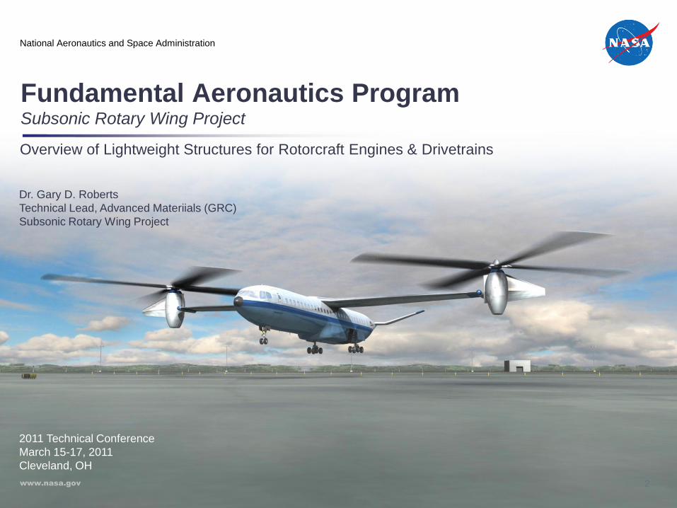
SRW Project Organization
10/01/2010
Project Manager: Susan Gorton
Deputy Project Manager: Isaac López
Additional Functions as Needed
Deputy Project
Manager For
ARC: Bob Kufeld
Deputy Project
Manager For
GRC: TBD
Deputy Project
Manager For
LaRC: Odilyn Luck
Aero (AUA, TH, TNF) Aero (RTI)
Engines (RTT, RXN,
RX)
Aero (D301, D302,
D303, D308, D502)
FD&C (AUA, TH, TI)
MDATD (RTM)
Experimental Capabilities: L. Jenkins
Aeromechanics: T. Norman
Engines: J. Welch; G. Roberts
Drive Trains: R. Handschuh
PR
OJE
CT
LE
VE
LS
UB
-PR
OJE
CT
LE
VE
L
Flight Dynamics and Control: C. Theodore
Multi-disciplinary Concepts: G. Yamauchi
Business Support Team(Lead Analyst: D. Findley)
Scheduler: J. Moran
Business Support Team(Center Analyst: P. Stacy)
Structures: K. Jackson; K. O’Brien
Acoustics: D. Boyd; R. Cabell
ExCap (AUA, AOX) ExCap (D303, D304)
Drive Train (RX,
RXN)
MDATD (AUA)
STR (D309, D312,
D313, D322)
Acoustics (D314,
D321, D307)
AR
C
GR
C
LaR
C
Technical
Challenges
01/31/2011
Business Support Team(Center Analyst: B.
Bertsch)
4
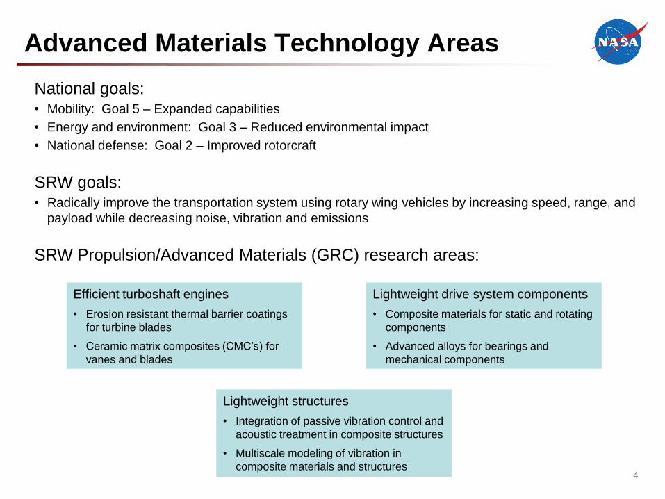
Advanced Materials Technology Areas
National goals:• Mobility: Goal 5 – Expanded capabilities
• Energy and environment: Goal 3 – Reduced environmental impact
• National defense: Goal 2 – Improved rotorcraft
SRW goals:• Radically improve the transportation system using rotary wing vehicles by increasing speed, range, and
payload while decreasing noise, vibration and emissions
SRW Propulsion/Advanced Materials (GRC) research areas:
Efficient turboshaft engines
• Erosion resistant thermal barrier coatings
for turbine blades
• Ceramic matrix composites (CMC’s) for
vanes and blades
Lightweight structures
• Integration of passive vibration control and
acoustic treatment in composite structures
• Multiscale modeling of vibration in
composite materials and structures
Lightweight drive system components
• Composite materials for static and rotating
components
• Advanced alloys for bearings and
mechanical components
5
Erosion resistant thermal barrier coatings
Technology description: (POC: Bob Miller)
• Develop advanced erosion resistant thermal barrier coatings for turbine blades
• Optimize coating composition and deposition conditions for blade geometries
• Develop physics based erosion model
Technical challenges:
• Optimize coating composition and microstructure for erosion resistance under the combined effects of
temperature and oxidation
• Develop a laboratory test rig that replicates the erosion damage observed in engines
• Fully understand and model effects of microstructure, environment, and particulates on TBC erosion
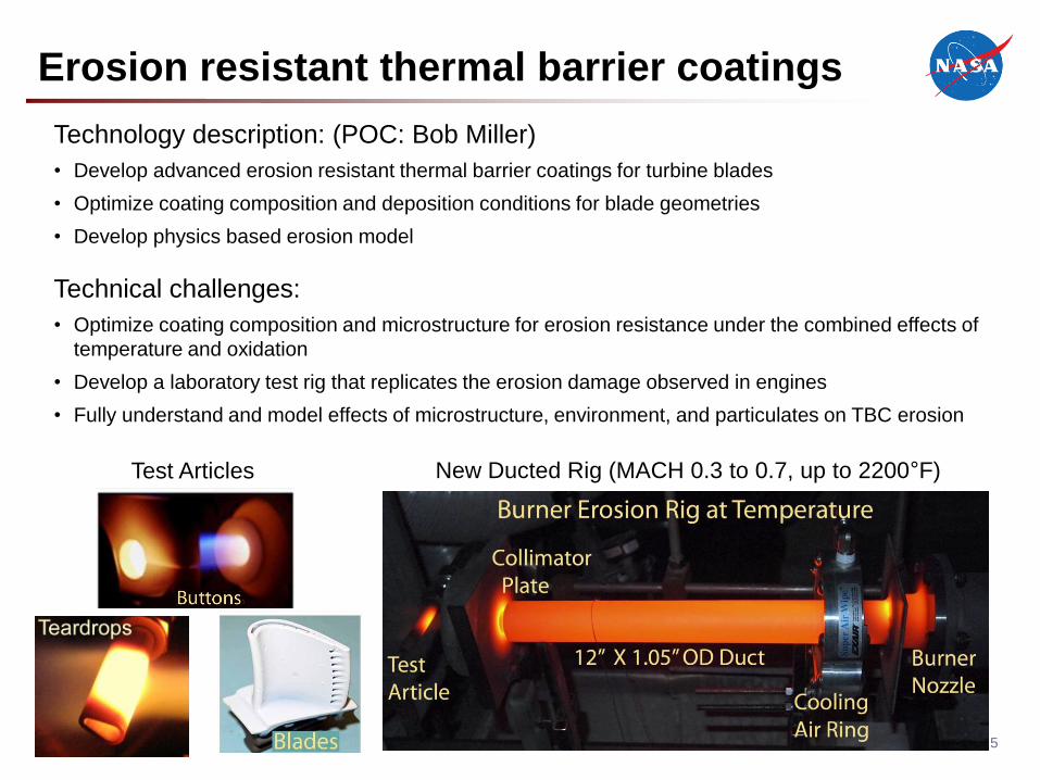
Test Articles New Ducted Rig (MACH 0.3 to 0.7, up to 2200°F)
6
Erosion resistant thermal barrier coatings
Rotorcraft applications:
• Coatings for turbine blades in turboshaft engines
Benefits:
• Coatings with improved erosion resistance at higher temperatures enable engine operation at higher
power density (higher temperature and pressure)
• Reduced fuel burn, reduced emissions, and lower weight
• Improved sintering and erosion resistance results in greater reliability and reduced maintenance
Contracts and external agreements:
• Improved coating technology is ready for engine testing if an opportunity becomes available
7
Erosion resistant thermal barrier coatings
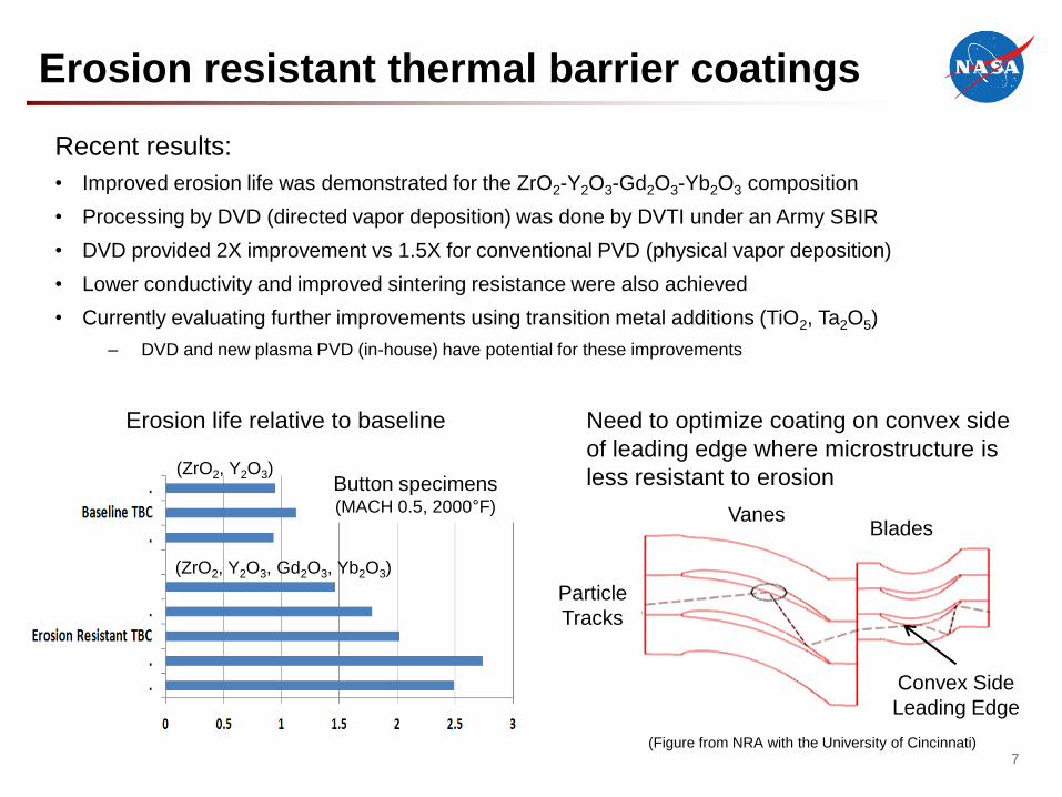
Recent results:
• Improved erosion life was demonstrated for the ZrO2-Y2O3-Gd2O3-Yb2O3 composition
• Processing by DVD (directed vapor deposition) was done by DVTI under an Army SBIR
• DVD provided 2X improvement vs 1.5X for conventional PVD (physical vapor deposition)
• Lower conductivity and improved sintering resistance were also achieved
• Currently evaluating further improvements using transition metal additions (TiO2, Ta2O5)
– DVD and new plasma PVD (in-house) have potential for these improvements
(ZrO2, Y2O3, Gd2O3, Yb2O3)
(ZrO2, Y2O3)Button specimens(MACH 0.5, 2000°F)
Erosion life relative to baseline Need to optimize coating on convex side
of leading edge where microstructure is
less resistant to erosion
Convex Side
Leading Edge
Particle
Tracks
VanesBlades
(Figure from NRA with the University of Cincinnati)
8
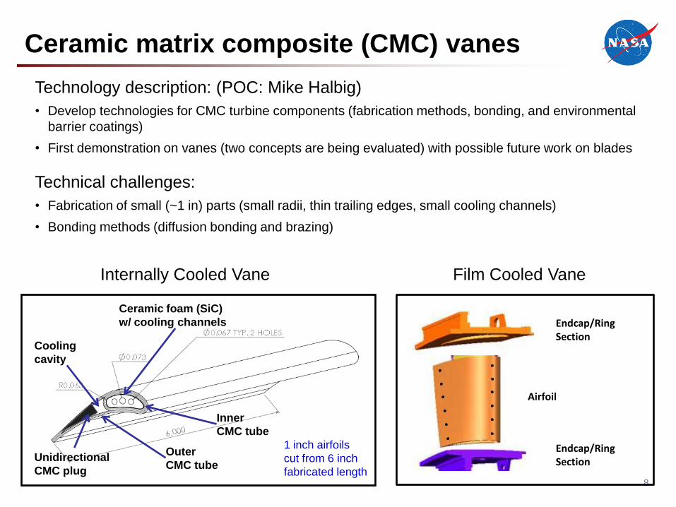
Ceramic matrix composite (CMC) vanes
Film Cooled Vane
Airfoil
Endcap/Ring Section
Endcap/Ring Section
Internally Cooled Vane
Unidirectional
CMC plug
Inner
CMC tube
Ceramic foam (SiC)
w/ cooling channels
Cooling
cavity
Outer
CMC tube
1 inch airfoils
cut from 6 inch
fabricated length
Technology description: (POC: Mike Halbig)
• Develop technologies for CMC turbine components (fabrication methods, bonding, and environmental
barrier coatings)
• First demonstration on vanes (two concepts are being evaluated) with possible future work on blades
Technical challenges:
• Fabrication of small (~1 in) parts (small radii, thin trailing edges, small cooling channels)
• Bonding methods (diffusion bonding and brazing)
9
Ceramic matrix composite (CMC) vanes
Rotorcraft applications:• HPT vanes in turboshaft engines
• Combustor liners, shrouds, blades of the HPT, and blades and vanes of the low pressure turbine
(LPT) stages
Benefits:
• Higher temperature capability of CMC vanes enables engine operation at higher power density
(higher temperature and pressure)
• Reduced fuel burn, reduced emissions, and lower weight
• Reduced cooling results in improved efficiency
Contracts and external agreements:• N&R Engineering (Phase 2 SBIR)
– Investigation of cooling schemes and stress analysis in the airfoil
10
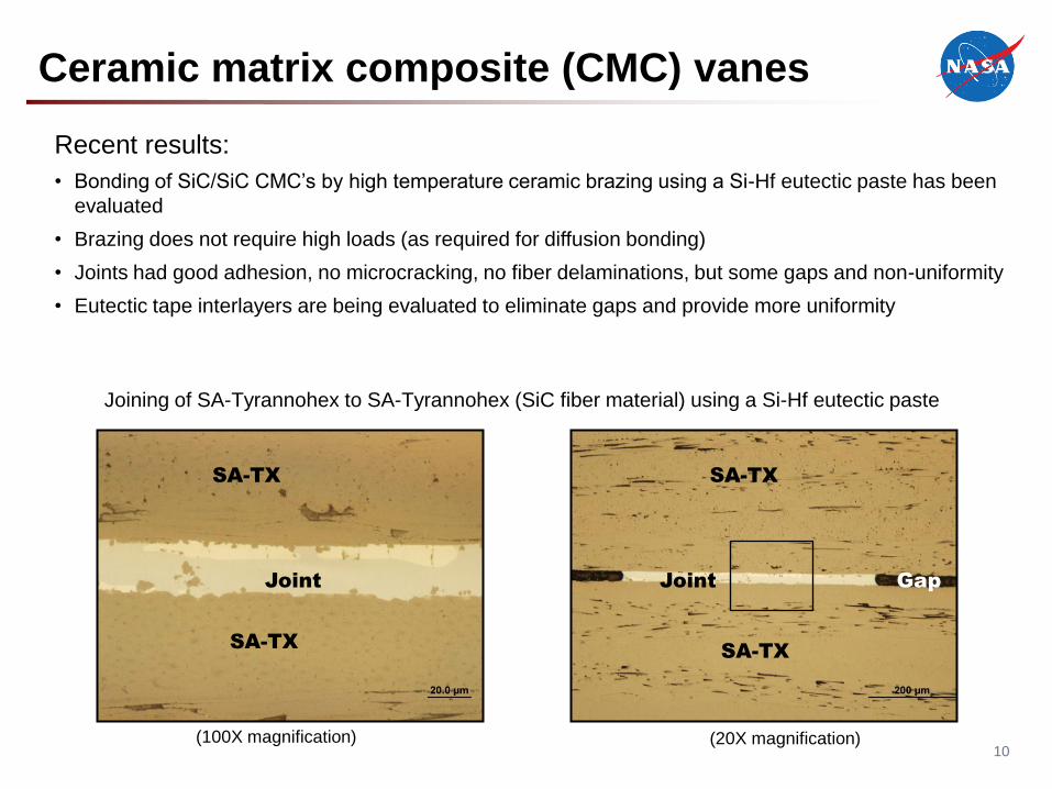
Ceramic matrix composite (CMC) vanes
Joining of SA-Tyrannohex to SA-Tyrannohex (SiC fiber material) using a Si-Hf eutectic paste
Recent results:
• Bonding of SiC/SiC CMC’s by high temperature ceramic brazing using a Si-Hf eutectic paste has been
evaluated
• Brazing does not require high loads (as required for diffusion bonding)
• Joints had good adhesion, no microcracking, no fiber delaminations, but some gaps and non-uniformity
• Eutectic tape interlayers are being evaluated to eliminate gaps and provide more uniformity
Joint
SA-TX
SA-TX
Joint Gap
SA-TX
SA-TX
(100X magnification) (20X magnification)
11
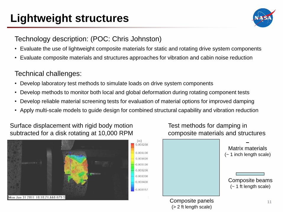
Lightweight structures
Technology description: (POC: Chris Johnston)
• Evaluate the use of lightweight composite materials for static and rotating drive system components
• Evaluate composite materials and structures approaches for vibration and cabin noise reduction
Technical challenges:
• Develop laboratory test methods to simulate loads on drive system components
• Develop methods to monitor both local and global deformation during rotating component tests
• Develop reliable material screening tests for evaluation of material options for improved damping
• Apply multi-scale models to guide design for combined structural capability and vibration reduction
Surface displacement with rigid body motion
subtracted for a disk rotating at 10,000 RPM
Test methods for damping in
composite materials and structures
Matrix materials(~ 1 inch length scale)
Composite beams(~ 1 ft length scale)
Composite panels(> 2 ft length scale)
12
Lightweight structures
Rotorcraft applications:• Lightweight shafts, couplings, housings, gears
• Passive approaches for control of vibration close to the source (gearbox)
• Airframe structure with integrated passive vibration and noise control
Benefits:• Significant weight reduction for future heavy lift and high speed vehicles
• Cabin noise and vibration reduction with minimum addition of parasitic weight
Partnerships:• Exploring possibilities for partnerships in these areas
13
Lightweight structures (vibration reduction)
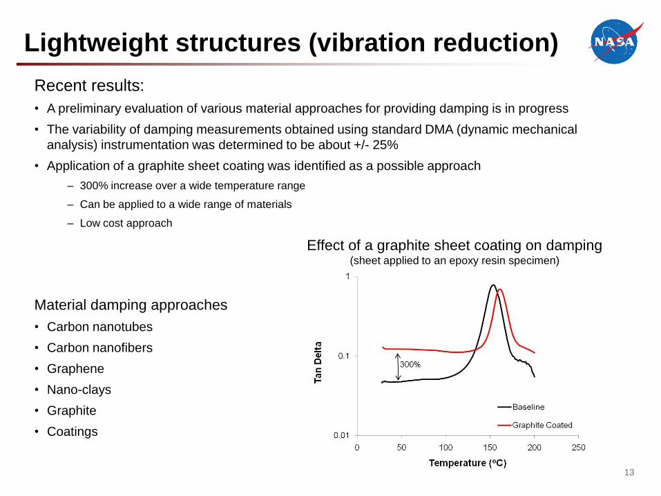
Recent results:
• A preliminary evaluation of various material approaches for providing damping is in progress
• The variability of damping measurements obtained using standard DMA (dynamic mechanical
analysis) instrumentation was determined to be about +/- 25%
• Application of a graphite sheet coating was identified as a possible approach
– 300% increase over a wide temperature range
– Can be applied to a wide range of materials
– Low cost approach
Material damping approaches
• Carbon nanotubes
• Carbon nanofibers
• Graphene
• Nano-clays
• Graphite
• Coatings
Effect of a graphite sheet coating on damping(sheet applied to an epoxy resin specimen)
14
60-NiTiNOL Metal Alloy
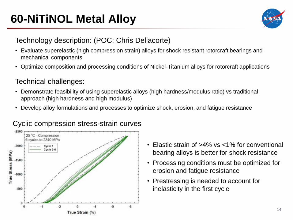
Technology description: (POC: Chris Dellacorte)
• Evaluate superelastic (high compression strain) alloys for shock resistant rotorcraft bearings and
mechanical components
• Optimize composition and processing conditions of Nickel-Titanium alloys for rotorcraft applications
Technical challenges:
• Demonstrate feasibility of using superelastic alloys (high hardness/modulus ratio) vs traditional
approach (high hardness and high modulus)
• Develop alloy formulations and processes to optimize shock, erosion, and fatigue resistance
• Elastic strain of >4% vs <1% for conventional
bearing alloys is better for shock resistance
• Processing conditions must be optimized for
erosion and fatigue resistance
• Prestressing is needed to account for
inelasticity in the first cycle
Cyclic compression stress-strain curves
15
60-NiTiNOL Metal Alloy
Rotorcraft applications:• Bearings, gears, main and tail rotor mechanisms, and driveline components
Benefits:• 60NiTi compared to conventional steel alloys:
• 15% lighter
• Can endure 10X higher concentrated shock-impact loads
• Immune to corrosion
• These capabilities offer the potential for smaller/lighter weight components and more robust and
reliable mechanical systems
Partnerships:• Pathfinder project to design and fabricate 50mm ball bearing for aerospace use. Team includes
bearing manufacturers, multiple NASA Centers and support from both ARMD and the NESC.
16
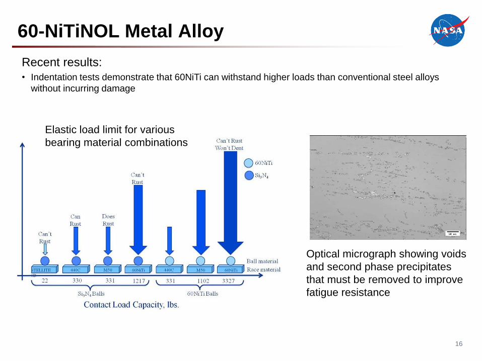
60-NiTiNOL Metal Alloy
Recent results:• Indentation tests demonstrate that 60NiTi can withstand higher loads than conventional steel alloys
without incurring damage
Optical micrograph showing voids
and second phase precipitates
that must be removed to improve
fatigue resistance
Elastic load limit for various
bearing material combinations

1717Your Title Here 17