Embed Size (px)
Citation preview
Overview of Disc Brakes and Related Phenomena - a review
Asim Rashid
Linköping University Post Print
N.B.: When citing this work, cite the original article.
Original Publication:
Asim Rashid , Overview of Disc Brakes and Related Phenomena - a review, 2014, International Journal of Vehicle Noise and Vibration, 10(4), pp. 257-301. http://dx.doi.org/10.1504/IJVNV.2014.065634 Copyright: Inderscience Publishers
URL: http://www.inderscience.com/
Postprint available at: Linköping University Electronic Press http://urn.kb.se/resolve?urn=urn:nbn:se:liu:diva-124566
Int.
J.Veh
icle
Nois
ean
dV
ibra
tion
,Vol.
10,N
o.4
,pp
.257..301
Overview of Disc Brakes and Related Phenomena - a review 1
Overview of Disc Brakes and Related Phenomena - a
review
Asim Rashid
Department of Mechanical Engineering,Jönköping University,SE-55111 Jönköping, SwedenE-mail: [email protected]
Abstract: Disc brakes have evolved over time to be a reliable method ofdecelerating and stopping a vehicle. There have been different designs ofdisc brake systems for different applications. This review gives a detaileddescription of different geometries of the components and the materials usedin a disc brake system. In spite of all the improvements, there are stillmany operational issues related to disc brakes that need to be understoodin a greater detail and resolved. There has been a lot of research going onabout these issues and at the same time different methods are being proposedto eliminate or reduce them. There has also been an intensive fundamentalresearch going on about the evolution of tribological interface of disc-padsystem. One major purpose of the present paper is to give a comprehensiveoverview of all such developments.
Keywords: disc brake, disc geometry, pad geometry, disc-pad tribology, brakefade, brake noise.
Biographical notes: Asim Rashid is a PhD candidate at School ofEngineering, Jönköping University. His research interests include non-linearfinite element analysis and contact mechanics.
1 Introduction
A vehicle requires a brake system to stop or adjust its speed with changing road andtraffic conditions. The basic principle used in braking systems is to convert the kineticenergy of a vehicle into some other form of energy. For example, in friction brakingit is converted into heat, and in regenerative braking it is converted into electricity orcompressed air etc. During a braking operation not all the kinetic energy is convertedinto the desired form, e.g. in friction braking some energy might be dissipated in theform of vibrations. In [1] a brief description of different brake systems used in a vehicleis given.
Two type of friction brakes, drum brakes and disc brakes, are widely used. Discbrakes as compared to drum brakes cool faster, due to larger swept area and relativelyhigher exposure to air flow, and show self cleaning ability due to centrifugal forces [2].Due to these reasons and some other advantages disc brakes have become the universal
Int.
J.Veh
icle
Nois
ean
dV
ibra
tion
,Vol.
10,N
o.4
,pp
.257..301
2 A. Rashid
Leading edge Trailing edge
Outboard cheek Inboard cheek
Inner padOuter pad
Disc
Axle
Direction of rotation
Inner edgeOuter edge
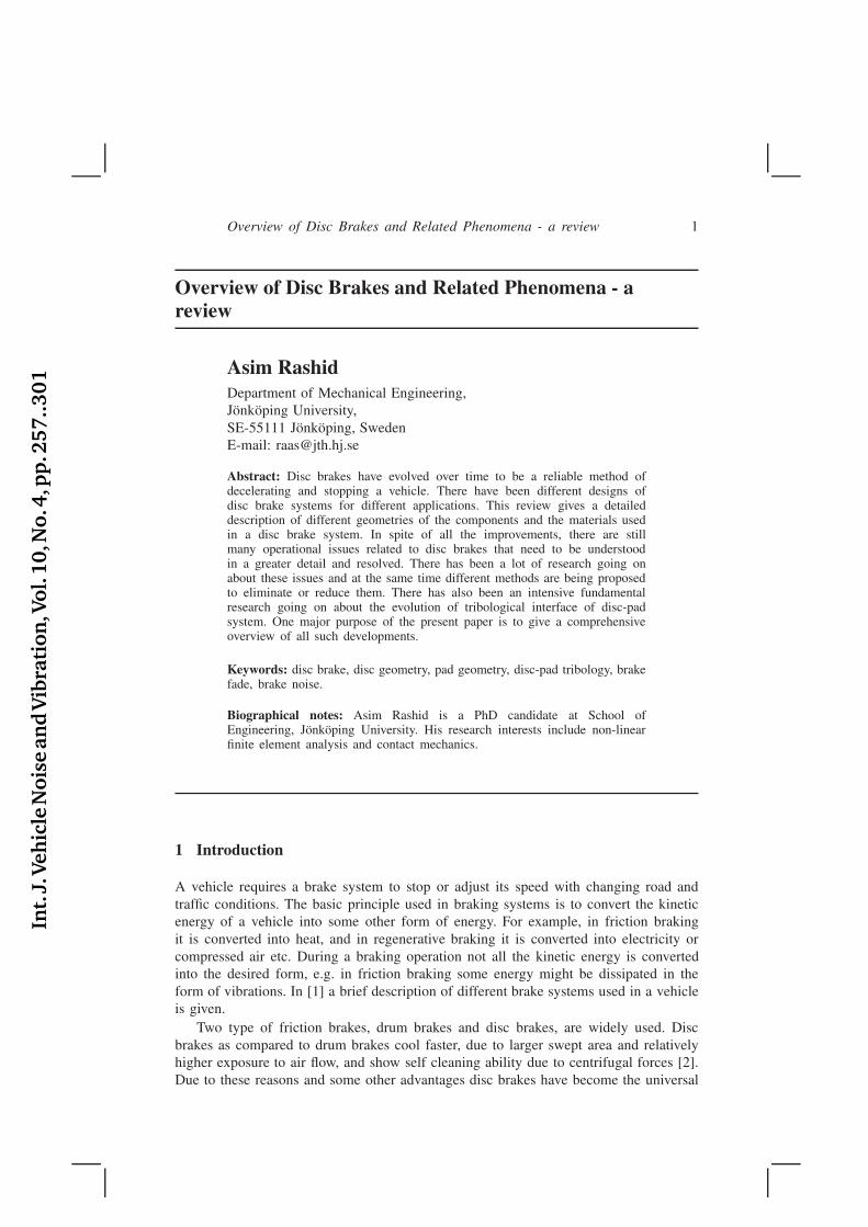
Figure 1: A simplified disc brake with the terminology in common use.
choice for front brakes on cars [2] and are also expected to dominate the truck marketin the near future [1].
This review paper consists of five major sections: Introduction, Disc brakes,Tribology, Operational issues and Conclusions. In the ’Disc brakes’ section, differentparts of a disc brake system are presented. Various configurations of parts, and materialare also discussed. In the ’Tribology’ section, changes happening at the contact interfaceare described. In the ’Operational issues’ section, the issues related to disc brakesencountered during brake application e.g. fade and noise will be described. Finally, in’Conclusion’ section, some concluding remarks are given.
2 Disc brakes
In a disc brake system, a set of pads is pressed against a rotating disc and due to friction,heat is generated at the disc-pad interface. This heat ultimately transfers to the vehicleand environment and the disc cools down. A simplified disc brake is shown in figure 1with the terminology which is in common use. The pad which is nearer to the center ofthe vehicle is called the inboard pad while the one that is away is called the outboardpad. Similarly friction surface of the disc which faces towards vehicle is called inboardcheek and the one which faces away is called outboard cheek. The edge of the padwhich comes into contact with a point on disc surface first is called leading edge whilethe edge which touches that point last is called trailing edge. The edge of the pad withsmaller radius is called inner edge while the one with larger radius is called outer edge.
A disc brake assembly consists of following major components: brake disc, pad,underlayer, back plate, shim and caliper. Now these components will be described inmore detail.
Int.
J.Veh
icle
Nois
ean
dV
ibra
tion
,Vol.
10,N
o.4
,pp
.257..301
Overview of Disc Brakes and Related Phenomena - a review 3
2.1 Brake disc
Brake disc, also called brake rotor, is fixed to the axle, so it rotates with the same speedas the wheel. Braking power of a disc brake is determined by the rate at which kineticenergy is converted into heat due to frictional forces between the pad and the disc.For an efficient brake design, it is also important that heat is dissipated as quickly aspossible otherwise the temperature of a disc might rise and affect the performance ofa disc brake. So to get an optimum performance in demanding applications, ventilationis introduced in the brake discs which increases the cooling rate. Brake discs could bedivided in two categories:
1. Solid brake discs
2. Ventilated brake discs
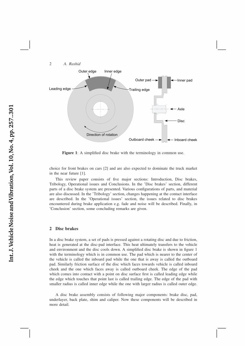
A solid brake disc is the simplest form and consists of a single solid disc. In aventilated disc, vanes or pillars or both separate two annular discs and provide a passagefor the air to flow. Ventilated brake discs increase the cooling rate and result in lowersurface temperature. This lower temperature reduces the risk of brake fade and alsohelps in reducing wear of the disc and pad. Both of these designs are constructed with orwithout a mounting bell. A mounting bell increases the distance from the friction surfaceto axle and the surface area of the disc which improves cooling [3] and therefore ithelps to protect the wheel bearings from the high temperature generated due to brakingoperation. A schematic description of these two types of discs is given in figure 2.
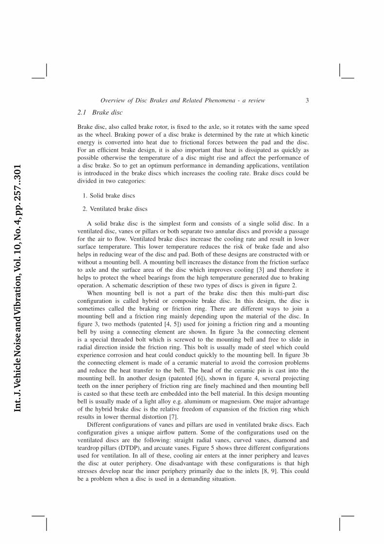
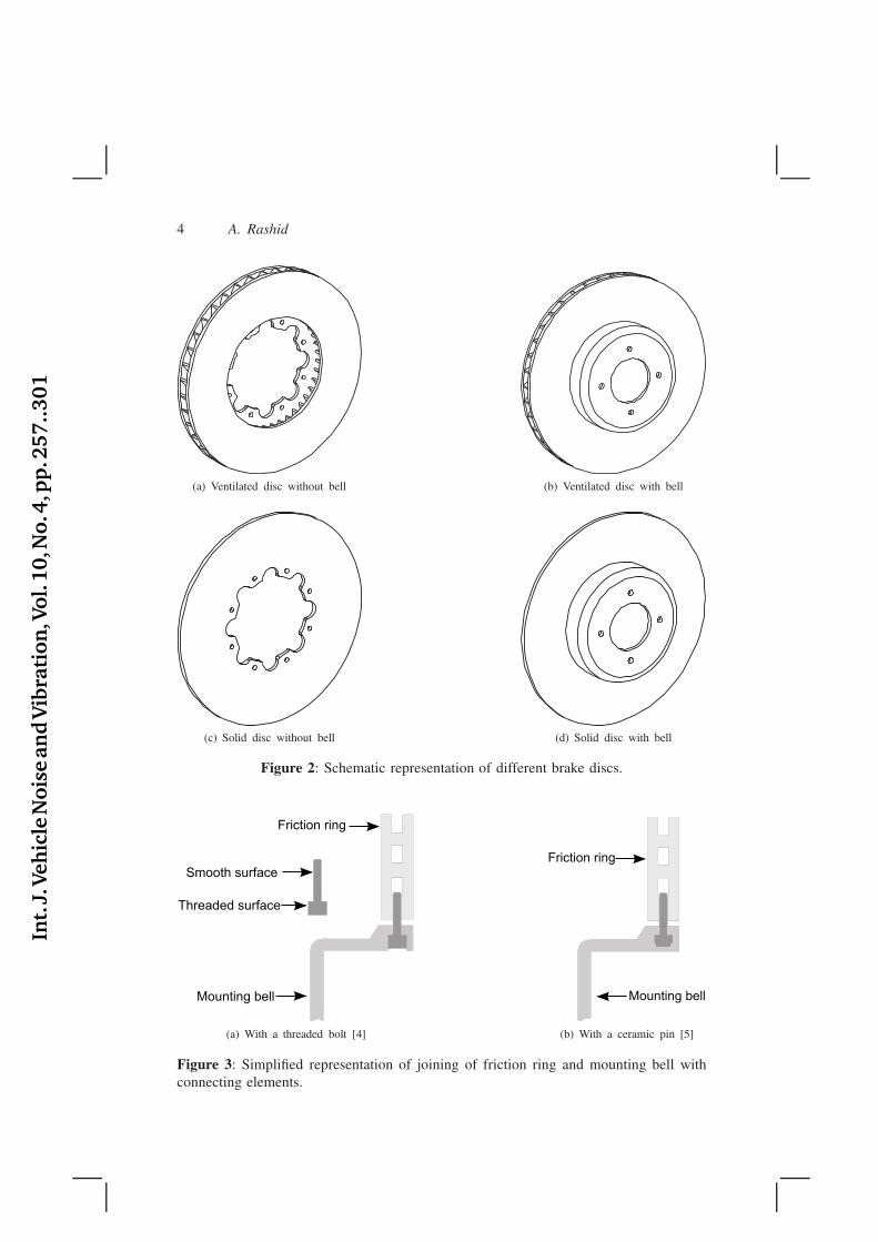
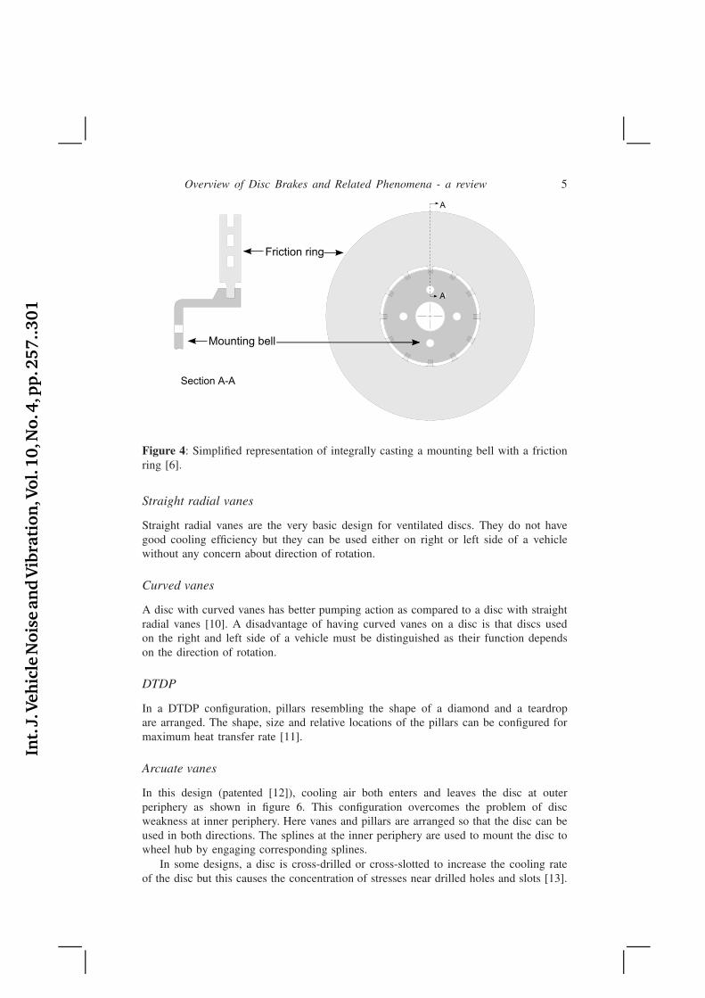
When mounting bell is not a part of the brake disc then this multi-part discconfiguration is called hybrid or composite brake disc. In this design, the disc issometimes called the braking or friction ring. There are different ways to join amounting bell and a friction ring mainly depending upon the material of the disc. Infigure 3, two methods (patented [4, 5]) used for joining a friction ring and a mountingbell by using a connecting element are shown. In figure 3a the connecting elementis a special threaded bolt which is screwed to the mounting bell and free to slide inradial direction inside the friction ring. This bolt is usually made of steel which couldexperience corrosion and heat could conduct quickly to the mounting bell. In figure 3bthe connecting element is made of a ceramic material to avoid the corrosion problemsand reduce the heat transfer to the bell. The head of the ceramic pin is cast into themounting bell. In another design (patented [6]), shown in figure 4, several projectingteeth on the inner periphery of friction ring are finely machined and then mounting bellis casted so that these teeth are embedded into the bell material. In this design mountingbell is usually made of a light alloy e.g. aluminum or magnesium. One major advantageof the hybrid brake disc is the relative freedom of expansion of the friction ring whichresults in lower thermal distortion [7].
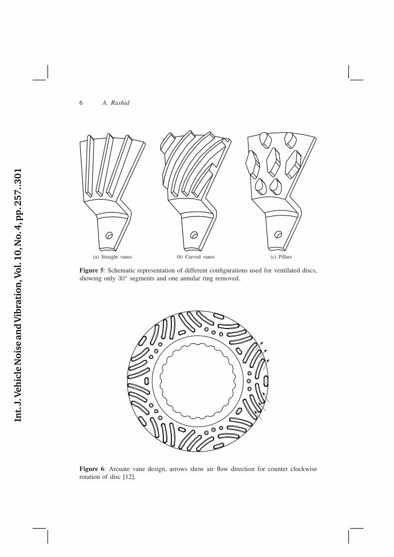
Different configurations of vanes and pillars are used in ventilated brake discs. Eachconfiguration gives a unique airflow pattern. Some of the configurations used on theventilated discs are the following: straight radial vanes, curved vanes, diamond andteardrop pillars (DTDP), and arcuate vanes. Figure 5 shows three different configurationsused for ventilation. In all of these, cooling air enters at the inner periphery and leavesthe disc at outer periphery. One disadvantage with these configurations is that highstresses develop near the inner periphery primarily due to the inlets [8, 9]. This couldbe a problem when a disc is used in a demanding situation.
Int.
J.Veh
icle
Nois
ean
dV
ibra
tion
,Vol.
10,N
o.4
,pp
.257..301
4 A. Rashid
(a) Ventilated disc without bell (b) Ventilated disc with bell
(c) Solid disc without bell (d) Solid disc with bell
Figure 2: Schematic representation of different brake discs.
Friction ring
Threaded surface
Smooth surface
Mounting bell
(a) With a threaded bolt [4]
Mounting bell
Friction ring
(b) With a ceramic pin [5]
Figure 3: Simplified representation of joining of friction ring and mounting bell withconnecting elements.
Int.
J.Veh
icle
Nois
ean
dV
ibra
tion
,Vol.
10,N
o.4
,pp
.257..301
Overview of Disc Brakes and Related Phenomena - a review 5
Mounting bell
Friction ring
A
A
Section A-A
A
Figure 4: Simplified representation of integrally casting a mounting bell with a frictionring [6].
Straight radial vanes
Straight radial vanes are the very basic design for ventilated discs. They do not havegood cooling efficiency but they can be used either on right or left side of a vehiclewithout any concern about direction of rotation.
Curved vanes
A disc with curved vanes has better pumping action as compared to a disc with straightradial vanes [10]. A disadvantage of having curved vanes on a disc is that discs usedon the right and left side of a vehicle must be distinguished as their function dependson the direction of rotation.
DTDP
In a DTDP configuration, pillars resembling the shape of a diamond and a teardropare arranged. The shape, size and relative locations of the pillars can be configured formaximum heat transfer rate [11].
Arcuate vanes
In this design (patented [12]), cooling air both enters and leaves the disc at outerperiphery as shown in figure 6. This configuration overcomes the problem of discweakness at inner periphery. Here vanes and pillars are arranged so that the disc can beused in both directions. The splines at the inner periphery are used to mount the disc towheel hub by engaging corresponding splines.
In some designs, a disc is cross-drilled or cross-slotted to increase the cooling rateof the disc but this causes the concentration of stresses near drilled holes and slots [13].
Int.
J.Veh
icle
Nois
ean
dV
ibra
tion
,Vol.
10,N
o.4
,pp
.257..301
6 A. Rashid
(a) Straight vanes (b) Curved vanes (c) Pillars
Figure 5: Schematic representation of different configurations used for ventilated discs,showing only 30◦ segments and one annular ring removed.
Figure 6: Arcuate vane design, arrows show air flow direction for counter clockwiserotation of disc [12].
Int.
J.Veh
icle
Nois
ean
dV
ibra
tion
,Vol.
10,N
o.4
,pp
.257..301
Overview of Disc Brakes and Related Phenomena - a review 7
Pad
Back plate Shim
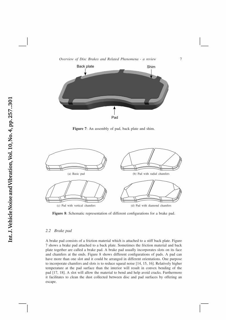
Figure 7: An assembly of pad, back plate and shim.
(a) Basic pad (b) Pad with radial chamfers
(c) Pad with vertical chamfers (d) Pad with diamond chamfers
Figure 8: Schematic representation of different configurations for a brake pad.
2.2 Brake pad
A brake pad consists of a friction material which is attached to a stiff back plate. Figure7 shows a brake pad attached to a back plate. Sometimes the friction material and backplate together are called a brake pad. A brake pad usually incorporates slots on its faceand chamfers at the ends. Figure 8 shows different configurations of pads. A pad canhave more than one slot and it could be arranged in different orientations. One purposeto incorporate chamfers and slots is to reduce squeal noise [14, 15, 16]. Relatively highertemperature at the pad surface than the interior will result in convex bending of thepad [17, 18]. A slot will allow the material to bend and help avoid cracks. Furthermoreit facilitates to clean the dust collected between disc and pad surfaces by offering anescape.
Int.
J.Veh
icle
Nois
ean
dV
ibra
tion
,Vol.
10,N
o.4
,pp
.257..301
8 A. Rashid
ShimUnderlayer
Friction material
Back plate
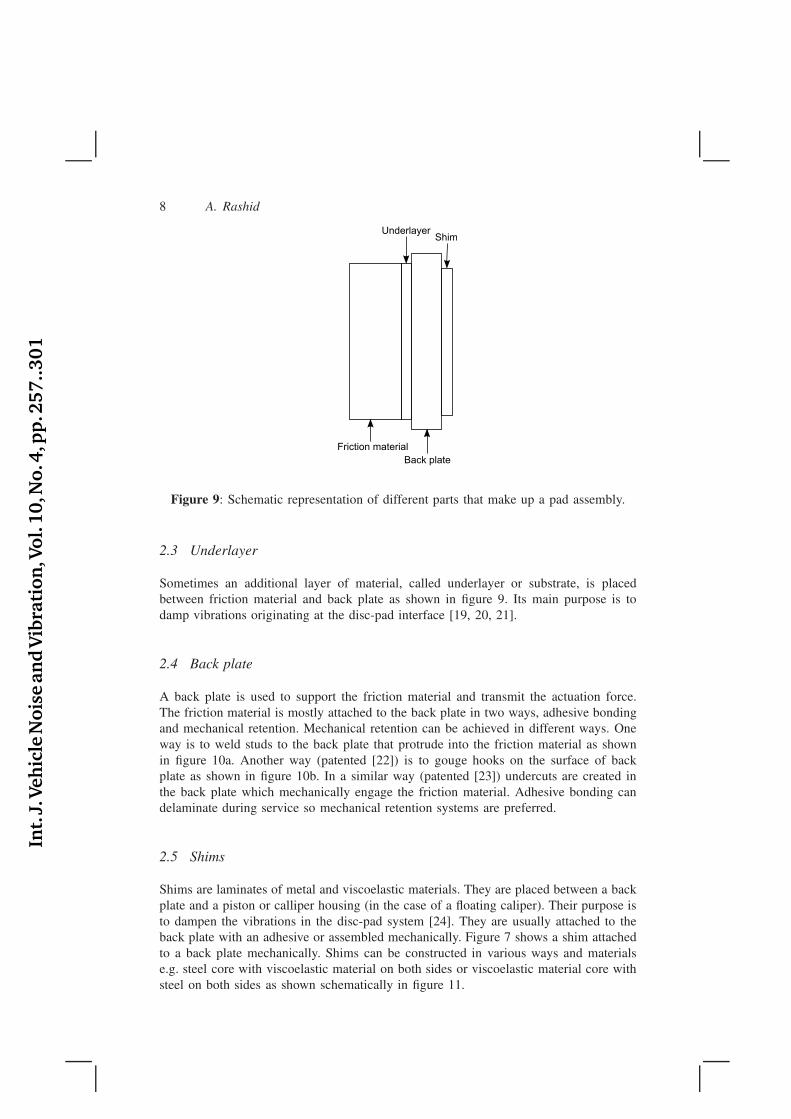
Figure 9: Schematic representation of different parts that make up a pad assembly.
2.3 Underlayer
Sometimes an additional layer of material, called underlayer or substrate, is placedbetween friction material and back plate as shown in figure 9. Its main purpose is todamp vibrations originating at the disc-pad interface [19, 20, 21].
2.4 Back plate
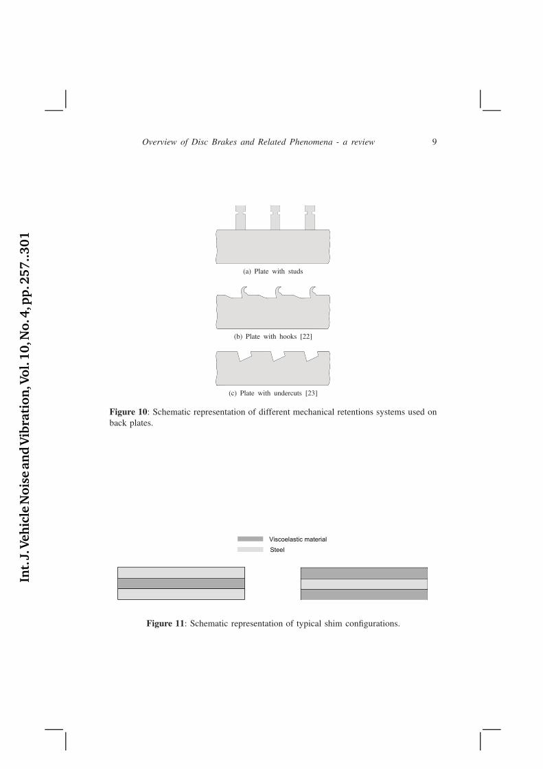
A back plate is used to support the friction material and transmit the actuation force.The friction material is mostly attached to the back plate in two ways, adhesive bondingand mechanical retention. Mechanical retention can be achieved in different ways. Oneway is to weld studs to the back plate that protrude into the friction material as shownin figure 10a. Another way (patented [22]) is to gouge hooks on the surface of backplate as shown in figure 10b. In a similar way (patented [23]) undercuts are created inthe back plate which mechanically engage the friction material. Adhesive bonding candelaminate during service so mechanical retention systems are preferred.
2.5 Shims
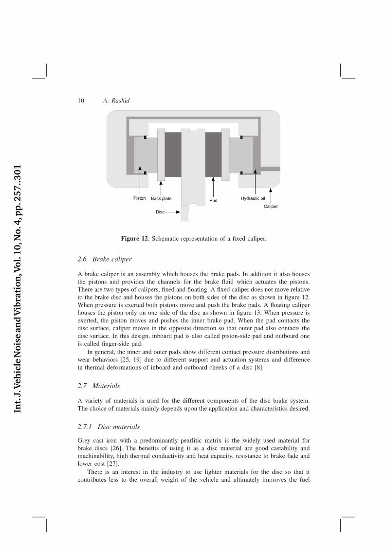
Shims are laminates of metal and viscoelastic materials. They are placed between a backplate and a piston or calliper housing (in the case of a floating caliper). Their purpose isto dampen the vibrations in the disc-pad system [24]. They are usually attached to theback plate with an adhesive or assembled mechanically. Figure 7 shows a shim attachedto a back plate mechanically. Shims can be constructed in various ways and materialse.g. steel core with viscoelastic material on both sides or viscoelastic material core withsteel on both sides as shown schematically in figure 11.
Int.
J.Veh
icle
Nois
ean
dV
ibra
tion
,Vol.
10,N
o.4
,pp
.257..301
Overview of Disc Brakes and Related Phenomena - a review 9
(a) Plate with studs
(b) Plate with hooks [22]
(c) Plate with undercuts [23]
Figure 10: Schematic representation of different mechanical retentions systems used onback plates.
Steel
Viscoelastic material
Figure 11: Schematic representation of typical shim configurations.
Int.
J.Veh
icle
Nois
ean
dV
ibra
tion
,Vol.
10,N
o.4
,pp
.257..301
10 A. Rashid
Hydraulic oil
Disc
Back platePiston
Caliper
Pad
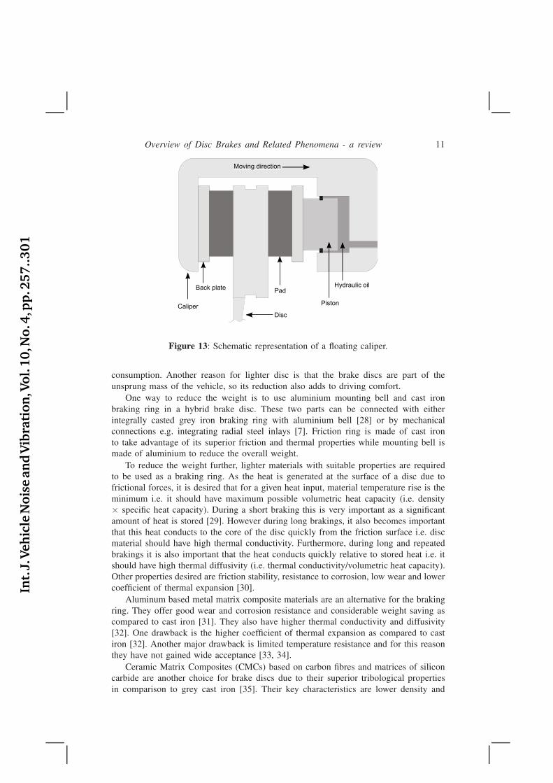
Figure 12: Schematic representation of a fixed caliper.
2.6 Brake caliper
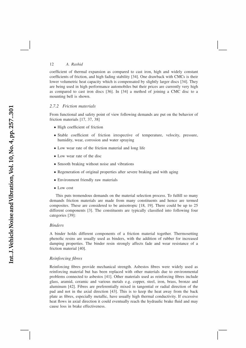
A brake caliper is an assembly which houses the brake pads. In addition it also housesthe pistons and provides the channels for the brake fluid which actuates the pistons.There are two types of calipers, fixed and floating. A fixed caliper does not move relativeto the brake disc and houses the pistons on both sides of the disc as shown in figure 12.When pressure is exerted both pistons move and push the brake pads. A floating caliperhouses the piston only on one side of the disc as shown in figure 13. When pressure isexerted, the piston moves and pushes the inner brake pad. When the pad contacts thedisc surface, caliper moves in the opposite direction so that outer pad also contacts thedisc surface. In this design, inboard pad is also called piston-side pad and outboard oneis called finger-side pad.
In general, the inner and outer pads show different contact pressure distributions andwear behaviors [25, 19] due to different support and actuation systems and differencein thermal deformations of inboard and outboard cheeks of a disc [8].
2.7 Materials
A variety of materials is used for the different components of the disc brake system.The choice of materials mainly depends upon the application and characteristics desired.
2.7.1 Disc materials
Grey cast iron with a predominantly pearlitic matrix is the widely used material forbrake discs [26]. The benefits of using it as a disc material are good castability andmachinability, high thermal conductivity and heat capacity, resistance to brake fade andlower cost [27].
There is an interest in the industry to use lighter materials for the disc so that itcontributes less to the overall weight of the vehicle and ultimately improves the fuel
Int.
J.Veh
icle
Nois
ean
dV
ibra
tion
,Vol.
10,N
o.4
,pp
.257..301
Overview of Disc Brakes and Related Phenomena - a review 11
Hydraulic oil
Disc
Back plate
PistonCaliper
Pad
Moving directionMoving direction
Figure 13: Schematic representation of a floating caliper.
consumption. Another reason for lighter disc is that the brake discs are part of theunsprung mass of the vehicle, so its reduction also adds to driving comfort.
One way to reduce the weight is to use aluminium mounting bell and cast ironbraking ring in a hybrid brake disc. These two parts can be connected with eitherintegrally casted grey iron braking ring with aluminium bell [28] or by mechanicalconnections e.g. integrating radial steel inlays [7]. Friction ring is made of cast ironto take advantage of its superior friction and thermal properties while mounting bell ismade of aluminium to reduce the overall weight.
To reduce the weight further, lighter materials with suitable properties are requiredto be used as a braking ring. As the heat is generated at the surface of a disc due tofrictional forces, it is desired that for a given heat input, material temperature rise is theminimum i.e. it should have maximum possible volumetric heat capacity (i.e. density× specific heat capacity). During a short braking this is very important as a significantamount of heat is stored [29]. However during long brakings, it also becomes importantthat this heat conducts to the core of the disc quickly from the friction surface i.e. discmaterial should have high thermal conductivity. Furthermore, during long and repeatedbrakings it is also important that the heat conducts quickly relative to stored heat i.e. itshould have high thermal diffusivity (i.e. thermal conductivity/volumetric heat capacity).Other properties desired are friction stability, resistance to corrosion, low wear and lowercoefficient of thermal expansion [30].
Aluminum based metal matrix composite materials are an alternative for the brakingring. They offer good wear and corrosion resistance and considerable weight saving ascompared to cast iron [31]. They also have higher thermal conductivity and diffusivity[32]. One drawback is the higher coefficient of thermal expansion as compared to castiron [32]. Another major drawback is limited temperature resistance and for this reasonthey have not gained wide acceptance [33, 34].
Ceramic Matrix Composites (CMCs) based on carbon fibres and matrices of siliconcarbide are another choice for brake discs due to their superior tribological propertiesin comparison to grey cast iron [35]. Their key characteristics are lower density and
Int.
J.Veh
icle
Nois
ean
dV
ibra
tion
,Vol.
10,N
o.4
,pp
.257..301
12 A. Rashid
coefficient of thermal expansion as compared to cast iron, high and widely constantcoefficients of friction, and high fading stability [34]. One drawback with CMCs is theirlower volumetric heat capacity which is compensated by slightly larger discs [34]. Theyare being used in high performance automobiles but their prices are currently very highas compared to cast iron discs [36]. In [34] a method of joining a CMC disc to amounting bell is shown.
2.7.2 Friction materials
From functional and safety point of view following demands are put on the behavior offriction materials [17, 37, 38]
• High coefficient of friction
• Stable coefficient of friction irrespective of temperature, velocity, pressure,humidity, wear, corrosion and water spraying
• Low wear rate of the friction material and long life
• Low wear rate of the disc
• Smooth braking without noise and vibrations
• Regeneration of original properties after severe braking and with aging
• Environment friendly raw materials
• Low cost
This puts tremendous demands on the material selection process. To fulfill so manydemands friction materials are made from many constituents and hence are termedcomposites. These are considered to be anisotropic [18, 19]. There could be up to 25different components [3]. The constituents are typically classified into following fourcategories [39]:
Binders
A binder holds different components of a friction material together. Thermosettingphenolic resins are usually used as binders, with the addition of rubber for increaseddamping properties. The binder resin strongly affects fade and wear resistance of afriction material [40].
Reinforcing fibres
Reinforcing fibres provide mechanical strength. Asbestos fibres were widely used asreinforcing material but has been replaced with other materials due to environmentalproblems connected to asbestos [41]. Other materials used as reinforcing fibres includeglass, aramid, ceramic and various metals e.g. copper, steel, iron, brass, bronze andaluminum [42]. Fibres are preferentially mixed in tangential or radial direction of thepad and not in the axial direction [43]. This is to keep the heat away from the backplate as fibres, especially metallic, have usually high thermal conductivity. If excessiveheat flows in axial direction it could eventually reach the hydraulic brake fluid and maycause loss in brake effectiveness.
Int.
J.Veh
icle
Nois
ean
dV
ibra
tion
,Vol.
10,N
o.4
,pp
.257..301
Overview of Disc Brakes and Related Phenomena - a review 13
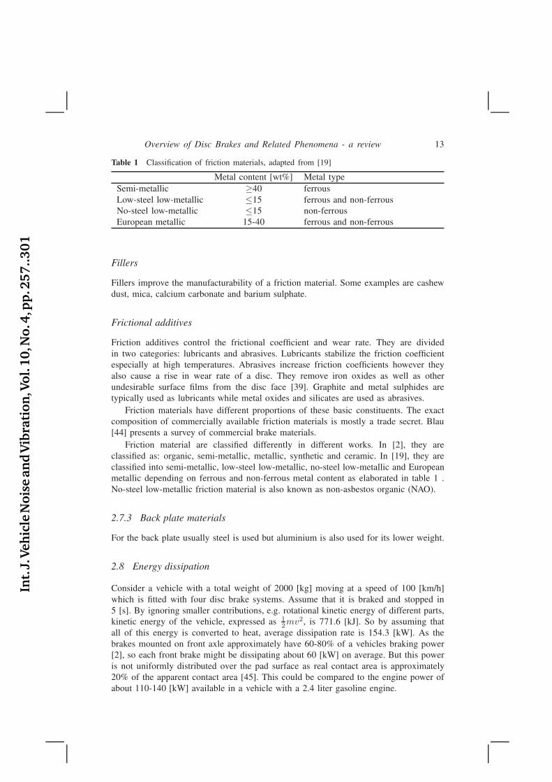
Table 1 Classification of friction materials, adapted from [19]
Metal content [wt%] Metal typeSemi-metallic ≥40 ferrousLow-steel low-metallic ≤15 ferrous and non-ferrousNo-steel low-metallic ≤15 non-ferrousEuropean metallic 15-40 ferrous and non-ferrous
Fillers
Fillers improve the manufacturability of a friction material. Some examples are cashewdust, mica, calcium carbonate and barium sulphate.
Frictional additives
Friction additives control the frictional coefficient and wear rate. They are dividedin two categories: lubricants and abrasives. Lubricants stabilize the friction coefficientespecially at high temperatures. Abrasives increase friction coefficients however theyalso cause a rise in wear rate of a disc. They remove iron oxides as well as otherundesirable surface films from the disc face [39]. Graphite and metal sulphides aretypically used as lubricants while metal oxides and silicates are used as abrasives.
Friction materials have different proportions of these basic constituents. The exactcomposition of commercially available friction materials is mostly a trade secret. Blau[44] presents a survey of commercial brake materials.
Friction material are classified differently in different works. In [2], they areclassified as: organic, semi-metallic, metallic, synthetic and ceramic. In [19], they areclassified into semi-metallic, low-steel low-metallic, no-steel low-metallic and Europeanmetallic depending on ferrous and non-ferrous metal content as elaborated in table 1 .No-steel low-metallic friction material is also known as non-asbestos organic (NAO).
2.7.3 Back plate materials
For the back plate usually steel is used but aluminium is also used for its lower weight.
2.8 Energy dissipation
Consider a vehicle with a total weight of 2000 [kg] moving at a speed of 100 [km/h]which is fitted with four disc brake systems. Assume that it is braked and stopped in5 [s]. By ignoring smaller contributions, e.g. rotational kinetic energy of different parts,kinetic energy of the vehicle, expressed as 1
2mv2, is 771.6 [kJ]. So by assuming thatall of this energy is converted to heat, average dissipation rate is 154.3 [kW]. As thebrakes mounted on front axle approximately have 60-80% of a vehicles braking power[2], so each front brake might be dissipating about 60 [kW] on average. But this poweris not uniformly distributed over the pad surface as real contact area is approximately20% of the apparent contact area [45]. This could be compared to the engine power ofabout 110-140 [kW] available in a vehicle with a 2.4 liter gasoline engine.
Int.
J.Veh
icle
Nois
ean
dV
ibra
tion
,Vol.
10,N
o.4
,pp
.257..301
14 A. Rashid
3 Tribology
Brake performance depends not only on the thermal and mechanical properties of discand friction materials but it is also affected by the topography of the mating surfaces andthe third body formed as a result of wear processes [45, 38]. So it becomes importantto have a good understanding of the changes happening at the contact interface to fullyunderstand the behavior of brakes. Before digging deeper into the tribology of discbrakes some fundamentals of friction and wear will be described.
3.1 Fundamentals of friction and wear
A tribological system is characterized by the frictional force and wear of the contactingsurfaces. In many engineering applications, friction is an unwanted phenomenon but inthe case of brakes it is very much desired. As the basic working principle of a brakeis the resistance force due to dry friction between rotor and pad so it deserves specialattention.
3.1.1 Friction
Friction can be described as resistance to the relative sliding motion of bodies in contact.An apparently polished and flat surface of a solid is not perfectly flat and containsirregularities if observed at magnification. These irregularities usually are found in theform of protrusions and depressions, called asperities and valleys, respectively. Whenone solid is pressed against another one, contact occurs at discrete contact spots. Thesum of the areas of all contact spots constitute the real area of contact and this is usuallyonly a small fraction of the apparent area of contact [46].
Friction is a complex phenomenon and result of different mechanisms at thecontacting surfaces at different scales. Some of the main mechanisms of dry friction are:adhesion, elastic and plastic deformation of asperities, ratcheting, fracture of asperitiesand third body mechanism [47].
As friction has strong influence on the performance of a brake system, its accuraterepresentation in the form of a mathematical model is very important for simulating thethermomechanical behavior. The goal of a friction model is to have a good agreementbetween predicted behavior and experimental observations. In general, many models offriction have been proposed in literature but non of them has succeeded to achieve wideacceptance [48]. So in many applications centuries old classic laws of friction are usedextensively.
Classic laws of friction
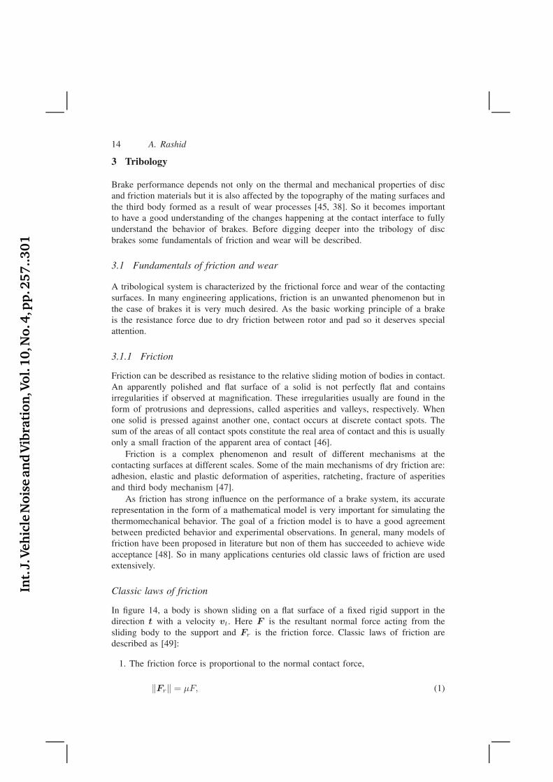
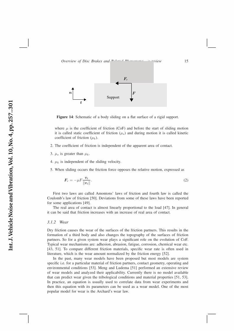
In figure 14, a body is shown sliding on a flat surface of a fixed rigid support in thedirection t with a velocity vt. Here F is the resultant normal force acting from thesliding body to the support and Fr is the friction force. Classic laws of friction aredescribed as [49]:
1. The friction force is proportional to the normal contact force,
‖Fr‖ = µF, (1)
Int.
J.Veh
icle
Nois
ean
dV
ibra
tion
,Vol.
10,N
o.4
,pp
.257..301
Overview of Disc Brakes and Related Phenomena - a review 15
F
Fr
t
n
Support
Figure 14: Schematic of a body sliding on a flat surface of a rigid support.
where µ is the coefficient of friction (CoF) and before the start of sliding motionit is called static coefficient of friction (µs) and during motion it is called kineticcoefficient of friction (µk).
2. The coefficient of friction is independent of the apparent area of contact.
3. µs is greater than µk.
4. µk is independent of the sliding velocity.
5. When sliding occurs the friction force opposes the relative motion, expressed as
Fr = −µFvt
‖vt‖. (2)
First two laws are called Amontons’ laws of friction and fourth law is called theCoulomb’s law of friction [50]. Deviations from some of these laws have been reportedfor some applications [49].
The real area of contact is almost linearly proportional to the load [47]. In generalit can be said that friction increases with an increase of real area of contact.
3.1.2 Wear
Dry friction causes the wear of the surfaces of the friction partners. This results in theformation of a third body and also changes the topography of the surfaces of frictionpartners. So for a given system wear plays a significant role on the evolution of CoF.Typical wear mechanisms are: adhesion, abrasion, fatigue, corrosion, chemical wear etc.[43, 51]. To compare different friction materials, specific wear rate is often used inliterature, which is the wear amount normalized by the friction energy [52].
In the past, many wear models have been proposed but most models are systemspecific i.e. for a particular material of friction partners, contact geometry, operating andenvironmental conditions [53]. Meng and Ludema [51] performed an extensive reviewof wear models and analyzed their applicability. Currently there is no model availablethat can predict wear given the tribological conditions and material properties [51, 53].In practice, an equation is usually used to correlate data from wear experiments andthen this equation with its parameters can be used as a wear model. One of the mostpopular model for wear is the Archard’s wear law.
Int.
J.Veh
icle
Nois
ean
dV
ibra
tion
,Vol.
10,N
o.4
,pp
.257..301
16 A. Rashid
Archard’s wear law
According to Archard’s wear law [54, 55] wear rate is proportional to the normal forceand sliding distance. This law is expressed as
∆W = kFs, (3)
where ∆W is the worn volume, k the coefficient of wear, F the applied load and s isthe sliding distance.
3.2 Tribological interface
Wear plays an important role in the evolution of tribological system of disc brakes.Due to different wear mechanisms, particles of varying sizes detach from pad and discsurfaces which are crushed and milled down to smaller particles while they are trappedbetween the contact surfaces [43, 56]. The mixing of these particles and oxidationcreates a new type of material called the third body [57]. Hard particles retain theiroriginal size whereas soft particles are milled together and finally end up with a verysmall grain size [38]. Part of the third body is stored in the contact area while the restis released from the system [58, 38]. Presence of the third body can be related to higherCoF. In [43], the third body was removed by blowing the pad and a reduction in CoFwas observed and if the bedding procedure is performed again, which recreates the thirdbody, the CoF would tend to assume high values again. In general it has been arguedthat due to plowing of the third body CoF increases for a system but it can also decreaseif some particles roll and serve as rolling bearings [47].
A third body can consist of all the elements of the friction material and the disc andmay also contain their oxides [43, 59, 38]. Furthermore chemical composition stronglydepends on the loading conditions during most recent brake applications [60, 43].Composition of the third body influences the CoF for a given tribological system[61, 43] e.g. diffusion of oxidized iron particles into the friction material affects theCoF of tribological system as shown by Severin and Dörsch [62]. Similarly Kemmershowed that CoF has a correlation to the amount of iron oxide particles in the interface[43]. He also claimed that thickness of the third body has an influence on the frictionalperformance but in the work by Wirth et al. [61] this was not observed.
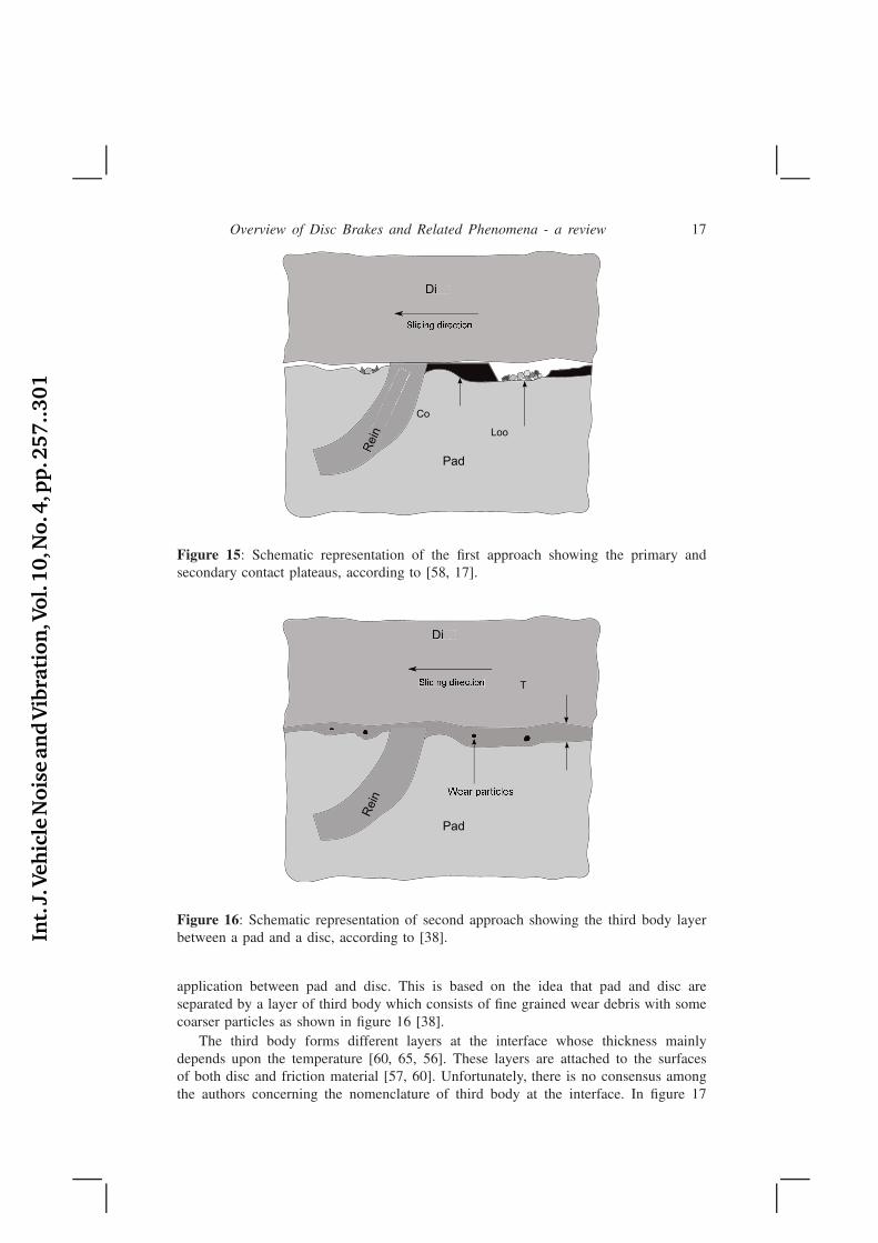
Owing to the variety of materials used for friction partners and lack of observationduring braking operation as most of the investigations reported in the literature involveexamination of contact surfaces after brake operation, there is a lack of agreementbetween researchers regarding the evolution of the contact interface. There have beenmainly two approaches to study the processes taking place at the pad-disc interface[38]. The first approach, presented in [45, 63, 17], relates the brake performance tothe formation, growth and degradation of contact plateaus. These contact plateaus, aspresented by Eriksson et al. [17], are formed due to removal of less wear resistantmaterial from pad surface which results in direct contact of more wear resistantconstituents typically reinforcing ingredients with the disc. Later the area of directcontact can grow by compaction of wear debris (third body) against primary plateaus,forming secondary plateaus as shown schematically in figure 15. These contact plateausconstitute about 10-20% of the apparent pad surface area [45]. It is supposed that mainenergy conversion happens at these plateaus [37]. The second approach [38, 56, 64,65, 60] relates the brake performance to the third body layers formed during brake
Int.
J.Veh
icle
Nois
ean
dV
ibra
tion
,Vol.
10,N
o.4
,pp
.257..301
Overview of Disc Brakes and Related Phenomena - a review 17
Disc
Pad
Rein
Co
Loo
Di
S������ ��������
Rein
Figure 15: Schematic representation of the first approach showing the primary andsecondary contact plateaus, according to [58, 17].
Disc
Pad
Rein
�� ��� ��������
Di
�� ��� �������� T
Figure 16: Schematic representation of second approach showing the third body layerbetween a pad and a disc, according to [38].
application between pad and disc. This is based on the idea that pad and disc areseparated by a layer of third body which consists of fine grained wear debris with somecoarser particles as shown in figure 16 [38].
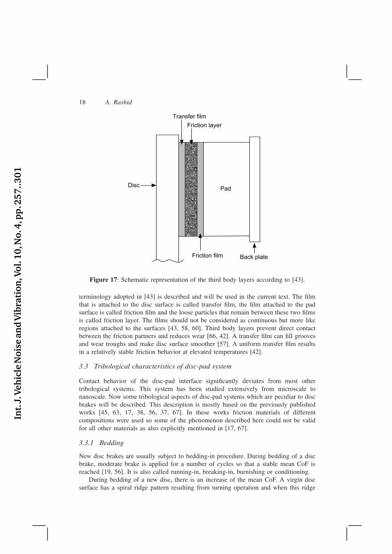
The third body forms different layers at the interface whose thickness mainlydepends upon the temperature [60, 65, 56]. These layers are attached to the surfacesof both disc and friction material [57, 60]. Unfortunately, there is no consensus amongthe authors concerning the nomenclature of third body at the interface. In figure 17
Int.
J.Veh
icle
Nois
ean
dV
ibra
tion
,Vol.
10,N
o.4
,pp
.257..301
18 A. Rashid
Transfer film
Friction layer
Friction film
DiscPad
Back plate
Figure 17: Schematic representation of the third body layers according to [43].
terminology adopted in [43] is described and will be used in the current text. The filmthat is attached to the disc surface is called transfer film, the film attached to the padsurface is called friction film and the loose particles that remain between these two filmsis called friction layer. The films should not be considered as continuous but more likeregions attached to the surfaces [43, 58, 60]. Third body layers prevent direct contactbetween the friction partners and reduces wear [66, 42]. A transfer film can fill groovesand wear troughs and make disc surface smoother [57]. A uniform transfer film resultsin a relatively stable friction behavior at elevated temperatures [42].
3.3 Tribological characteristics of disc-pad system
Contact behavior of the disc-pad interface significantly deviates from most othertribological systems. This system has been studied extensively from microscale tonanoscale. Now some tribological aspects of disc-pad systems which are peculiar to discbrakes will be described. This description is mostly based on the previously publishedworks [45, 63, 17, 38, 56, 37, 67]. In these works friction materials of differentcompositions were used so some of the phenomenon described here could not be validfor all other materials as also explicitly mentioned in [17, 67].
3.3.1 Bedding
New disc brakes are usually subject to bedding-in procedure. During bedding of a discbrake, moderate brake is applied for a number of cycles so that a stable mean CoF isreached [19, 56]. It is also called running-in, breaking-in, burnishing or conditioning.
During bedding of a new disc, there is an increase of the mean CoF. A virgin discsurface has a spiral ridge pattern resulting from turning operation and when this ridge
Int.
J.Veh
icle
Nois
ean
dV
ibra
tion
,Vol.
10,N
o.4
,pp
.257..301
Overview of Disc Brakes and Related Phenomena - a review 19
Ru
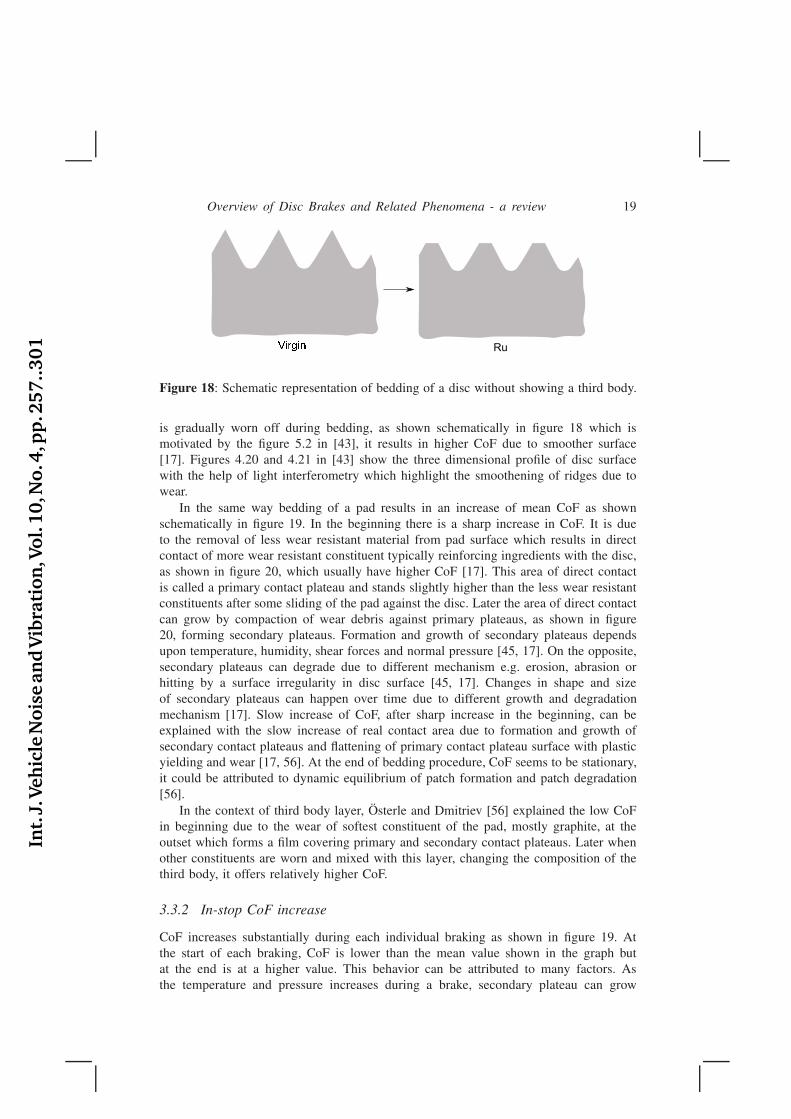
Figure 18: Schematic representation of bedding of a disc without showing a third body.
is gradually worn off during bedding, as shown schematically in figure 18 which ismotivated by the figure 5.2 in [43], it results in higher CoF due to smoother surface[17]. Figures 4.20 and 4.21 in [43] show the three dimensional profile of disc surfacewith the help of light interferometry which highlight the smoothening of ridges due towear.
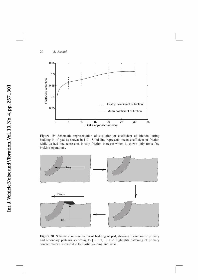
In the same way bedding of a pad results in an increase of mean CoF as shownschematically in figure 19. In the beginning there is a sharp increase in CoF. It is dueto the removal of less wear resistant material from pad surface which results in directcontact of more wear resistant constituent typically reinforcing ingredients with the disc,as shown in figure 20, which usually have higher CoF [17]. This area of direct contactis called a primary contact plateau and stands slightly higher than the less wear resistantconstituents after some sliding of the pad against the disc. Later the area of direct contactcan grow by compaction of wear debris against primary plateaus, as shown in figure20, forming secondary plateaus. Formation and growth of secondary plateaus dependsupon temperature, humidity, shear forces and normal pressure [45, 17]. On the opposite,secondary plateaus can degrade due to different mechanism e.g. erosion, abrasion orhitting by a surface irregularity in disc surface [45, 17]. Changes in shape and sizeof secondary plateaus can happen over time due to different growth and degradationmechanism [17]. Slow increase of CoF, after sharp increase in the beginning, can beexplained with the slow increase of real contact area due to formation and growth ofsecondary contact plateaus and flattening of primary contact plateau surface with plasticyielding and wear [17, 56]. At the end of bedding procedure, CoF seems to be stationary,it could be attributed to dynamic equilibrium of patch formation and patch degradation[56].
In the context of third body layer, Österle and Dmitriev [56] explained the low CoFin beginning due to the wear of softest constituent of the pad, mostly graphite, at theoutset which forms a film covering primary and secondary contact plateaus. Later whenother constituents are worn and mixed with this layer, changing the composition of thethird body, it offers relatively higher CoF.
3.3.2 In-stop CoF increase
CoF increases substantially during each individual braking as shown in figure 19. Atthe start of each braking, CoF is lower than the mean value shown in the graph butat the end is at a higher value. This behavior can be attributed to many factors. Asthe temperature and pressure increases during a brake, secondary plateau can grow
Int.
J.Veh
icle
Nois
ean
dV
ibra
tion
,Vol.
10,N
o.4
,pp
.257..301
20 A. Rashid
0 5 10 15 20 25 30 35
0.35
0.4
0.45
0.5
0.55
Brake application number
Coeffic
ient of fric
tion
Mean coefficient of firction
In-stop coefficient of friction
Figure 19: Schematic representation of evolution of coefficient of friction duringbedding-in of pad as shown in [17]. Solid line represents mean coefficient of frictionwhile dashed line represents in-stop friction increase which is shown only for a fewbraking operations.
Disc s
ReinRein
CoCo
Figure 20: Schematic representation of bedding of pad, showing formation of primaryand secondary plateaus according to [17, 37]. It also highlights flattening of primarycontact plateau surface due to plastic yielding and wear.
Int.
J.Veh
icle
Nois
ean
dV
ibra
tion
,Vol.
10,N
o.4
,pp
.257..301
Overview of Disc Brakes and Related Phenomena - a review 21
Low
Low
Coe
Te
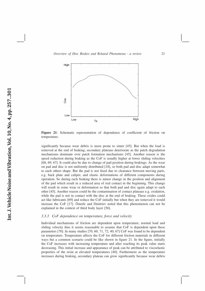
Figure 21: Schematic representation of dependence of coefficient of friction ontemperature.
significantly because wear debris is more prone to sinter [45]. But when the load isremoved at the end of braking, secondary plateaus deteriorate as the patch degradationmechanisms dominate over patch formation mechanisms [45]. Another reason is thespeed reduction during braking as the CoF is usually higher at lower sliding velocities[68, 69, 67]. It could also be due to change of pad position during brakings. As the wearon pad and disc is not uniformly distributed [18], so both pad and disc adapt somewhatto each others shape. But the pad is not fixed due to clearance between moving parts,e.g. back plate and caliper, and elastic deformations of different components duringoperation. So during each braking there is minor change in the position and alignmentof the pad which result in a reduced area of real contact in the beginning. This changewill result in some wear or deformation so that both pad and disc again adapt to eachother [45]. Another reason could be the contamination of contact plateaus e.g. oxidation,while the pad is not in contact with the disc at the end of braking. These oxides couldact like lubricants [69] and reduce the CoF initially but when they are removed it wouldincrease the CoF [17]. Österle and Dmitriev noted that this phenomenon can not beexplained in the context of third body layer [56].
3.3.3 CoF dependence on temperature, force and velocity
Individual mechanisms of friction are dependent upon temperature, normal load andsliding velocity thus it seems reasonable to assume that CoF is dependent upon theseparameters [70]. In many studies [70, 60, 71, 72, 40, 67] CoF was found to be dependenton temperature. Temperature affects the CoF for different friction materials in differentways but a common scenario could be like shown in figure 21. In the figure, initiallythe CoF increases with increasing temperature and after reaching its peak value startsdecreasing. This initial increase and appearance of peak can be attributed to viscoelasticproperties of the resin at elevated temperatures [40]. Furthermore as the temperatureincreases during braking, secondary plateau can grow significantly because wear debris
Int.
J.Veh
icle
Nois
ean
dV
ibra
tion
,Vol.
10,N
o.4
,pp
.257..301
22 A. Rashid
is more prone to sinter [45] and affecting the CoF positively. Later decrease of the CoFcan be attributed to thermal decomposition of the resin, aramid pulp and cashew particlesetc. [40, 72, 65]. This thermal decomposition can also lead to loosening and detachmentof fibres (primary contact plateaus) [56] which also affects the CoF negatively. In generalit could also be said that at higher temperatures, shear strength of materials decreaseswhich leads to a lower CoF [69].
In the context of third body layer, it has been observed that the third body formedat elevated temperature is rather thick (on the contrary, some studies also show decreasein thickness at elevated temperatures [65] ) and shows a layered structure [60, 56]. Easyshearing of the different layers along their interfaces explains the low CoF. Anotherreason for reduced CoF could be the presence of a thin carbonaceous film [60] at theinterface which act as a lubricant and support easy shearing between layers [56].
In many studies [70, 67, 59, 69, 42, 73, 52, 74] CoF was found to be dependenton braking force and velocity. In most of these studies CoF shows decreasing trendwith increasing velocity while it shows mixed trend with increasing load. An increasein braking force causes the elastic compression of the pad which quickly results in anincreased area of real contact for already engaged contact plateaus and also more contactplateaus become engaged [17]. Furthermore an increase of real contact area with theformation and growth of secondary contact plateaus, and flattening of primary contactplateau surface with plastic yielding and wear, also occurs although slowly. This increaseof real contact area explains the increase of frictional force with increased braking force.It can be said that intensity of the processes causing the increase of real contact areadetermine how the CoF behaves with increasing braking force.
In general, decrease of CoF at higher velocities can be explained as: Due to highervelocity there is less time for asperity contact and therefore less time for the deformationof asperities which results in reduction of real area of contact [47]. This reduction ofreal contact area causes the lower CoF.
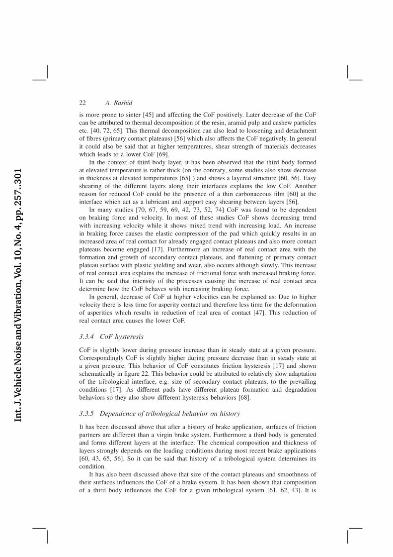
3.3.4 CoF hysteresis
CoF is slightly lower during pressure increase than in steady state at a given pressure.Correspondingly CoF is slightly higher during pressure decrease than in steady state ata given pressure. This behavior of CoF constitutes friction hysteresis [17] and shownschematically in figure 22. This behavior could be attributed to relatively slow adaptationof the tribological interface, e.g. size of secondary contact plateaus, to the prevailingconditions [17]. As different pads have different plateau formation and degradationbehaviors so they also show different hysteresis behaviors [68].
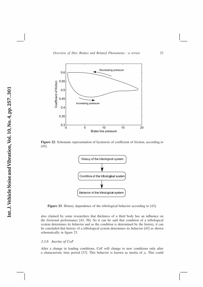
3.3.5 Dependence of tribological behavior on history
It has been discussed above that after a history of brake application, surfaces of frictionpartners are different than a virgin brake system. Furthermore a third body is generatedand forms different layers at the interface. The chemical composition and thickness oflayers strongly depends on the loading conditions during most recent brake applications[60, 43, 65, 56]. So it can be said that history of a tribological system determines itscondition.
It has also been discussed above that size of the contact plateaus and smoothness oftheir surfaces influences the CoF of a brake system. It has been shown that compositionof a third body influences the CoF for a given tribological system [61, 62, 43]. It is
Int.
J.Veh
icle
Nois
ean
dV
ibra
tion
,Vol.
10,N
o.4
,pp
.257..301
Overview of Disc Brakes and Related Phenomena - a review 23
0 5 10 15 200.3
0.35
0.4
0.45
0.5
0.55
0.6
Brake line pressure
Coeff
icie
nt
of
fric
tion
Decreasing pressure
Increasing pressure
Figure 22: Schematic representation of hysteresis of coefficient of friction, according to[45].
Conditio
logical
Figure 23: History dependence of the tribological behavior according to [43].
also claimed by some researchers that thickness of a third body has an influence onthe frictional performance [43, 56]. So it can be said that condition of a tribologicalsystem determines its behavior and as the condition is determined by the history, it canbe concluded that history of a tribological system determines its behavior [43] as shownschematically in figure 23.
3.3.6 Inertia of CoF
After a change in loading conditions, CoF will change to new conditions only aftera characteristic time period [37]. This behavior is known as inertia of µ. This could
Int.
J.Veh
icle
Nois
ean
dV
ibra
tion
,Vol.
10,N
o.4
,pp
.257..301
24 A. Rashid
Low
Low Te
Figure 24: Schematic representation of dependence of wear rate on temperature.
be explained with slow adaptation of the composition of the third body with changingloading conditions. The CoF for a given system depends on composition of the thirdbody [43] which by itself depends on the loading conditions [60]. The composition doesnot adapt instantaneously with the changing conditions instead takes some time to alter.The time required for the change of composition results in inertia of µ.
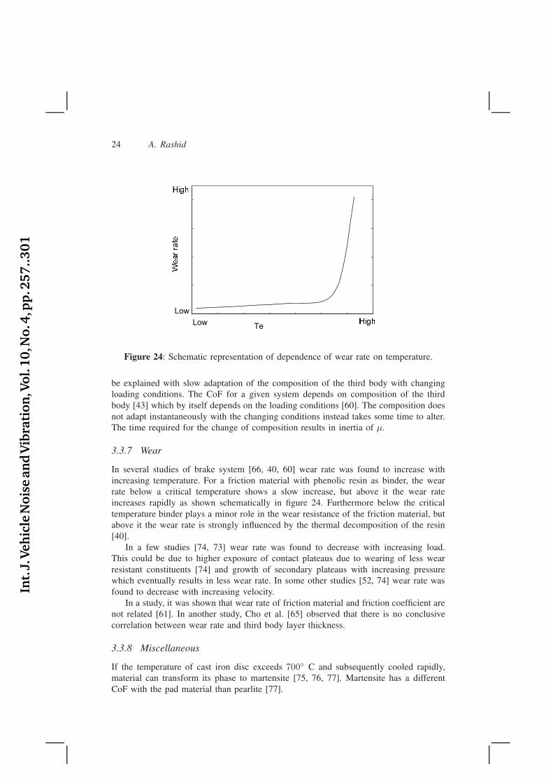
3.3.7 Wear
In several studies of brake system [66, 40, 60] wear rate was found to increase withincreasing temperature. For a friction material with phenolic resin as binder, the wearrate below a critical temperature shows a slow increase, but above it the wear rateincreases rapidly as shown schematically in figure 24. Furthermore below the criticaltemperature binder plays a minor role in the wear resistance of the friction material, butabove it the wear rate is strongly influenced by the thermal decomposition of the resin[40].
In a few studies [74, 73] wear rate was found to decrease with increasing load.This could be due to higher exposure of contact plateaus due to wearing of less wearresistant constituents [74] and growth of secondary plateaus with increasing pressurewhich eventually results in less wear rate. In some other studies [52, 74] wear rate wasfound to decrease with increasing velocity.
In a study, it was shown that wear rate of friction material and friction coefficient arenot related [61]. In another study, Cho et al. [65] observed that there is no conclusivecorrelation between wear rate and third body layer thickness.
3.3.8 Miscellaneous
If the temperature of cast iron disc exceeds 700◦ C and subsequently cooled rapidly,material can transform its phase to martensite [75, 76, 77]. Martensite has a differentCoF with the pad material than pearlite [77].
Int.
J.Veh
icle
Nois
ean
dV
ibra
tion
,Vol.
10,N
o.4
,pp
.257..301
Overview of Disc Brakes and Related Phenomena - a review 25
3.4 Models for friction phenomenon in brakes
To numerically simulate the behavior of disc brakes realistically, it is importantto represent the frictional behavior at the contact interface accurately. Complexityof tribological interface and interaction between different parameters make thedetermination of reliable and exact friction laws difficult [67]. Unfortunately manyresearchers use classic laws of friction in their sophisticated finite element analysiswhich is not sufficient. Now some friction models will be described which have beenspecifically developed for brakes. All the notations used to describe these friction modelshave been changed to be consistent in this paper.
Rhee [70] investigated the frictional properties of brakes for a semi-metallic frictionmaterial sliding against cast iron. He observed the frictional force to be dependent on thenormal load, sliding speed and temperature. He found the Amontons’ law unsatisfactoryto describe the friction behavior and instead proposed the the following equation.
Fr = µF avb at Ti, (4)
where Fr is the friction force, F the applied normal load, v the sliding speed, and a
and b are constants. In this model, µ is constant regardless of the load and speed butdependent on temperature, and a and b are also dependent upon temperature.
Thuresson [78] introduced the following equation to describe the correlation betweenCoF and temperature.
µ(T ) = µ0 − Tb, (5)
where µ0 is the CoF at the reference temperature T0 and b is a constant which can bedetermined by experiments.
Saffar et al. [52] introduced the following equation to describe the correlationbetween CoF and temperature.
µ = µ0 + k(T − T0)exp(−E
RT), (6)
where T0 is a reference temperature, µ0 the CoF at the reference temperature, R theuniversal gas constant, k a constant and E represents the activation energy that varieswith velocity. The parameters of this model can be obtained with the curve fittingprocedure based on the experimentally determined CoF vs. temperature graph.
Kemmer [43] performed experiments to find if the CoF depends upon sliding speed,temperature and pressure. He obtained the following expressions for two different padmaterials by using multi-variable regression.
µ = 0.234 + (8.5p− 5.15v + 3.05T )10−4 (7a)
µ = 0.334 + (−13.9p− 10.4v + 3.9T )10−4, (7b)
where p is the brake line pressure in [bar], v the vehicle velocity in [km/h] and T
is the temperature in [◦C]. A number of brake applications were performed to obtaindata for determination of these relations. A bedding procedure was performed beforeeach brake application to bring the tribological system to a comparable condition as abrake application might modify the interface. Kemmer noted that such expressions are
Int.
J.Veh
icle
Nois
ean
dV
ibra
tion
,Vol.
10,N
o.4
,pp
.257..301
26 A. Rashid
neither general nor universal and need to be determined for a given disc-pad system andoperation range.
Ostermeyer and Müller [37] proposed a dynamic friction law taking into account theinterconnection of the friction and temperature dynamics. It is a physically derived lawbased on the concept that tribological behavior is determined by growth and degradationof the contact plateaus. This is expressed by the following differential equations.
µ = −α((β + x(t))µ − γTP ) (8a)
TP = δ(TP − T0 − εx(t)), (8b)
where µ = µ(t) is current CoF, x(t) is the product of current normal force and currentvelocity, TP is the temperature of the patches, T0 is the integral disc temperature,α is the time constant for the CoF, β is the system parameter representing thecorrelation between the patch growth and the existing patch area, γ the system parameterrepresenting the correlation between the patch temperature and the patch growth, ε isthe system parameter representing the correlation between the friction power and thegenerated heat on the patch, and δ is the time constant for the patch temperature.It was shown that with the proper selection of the parameters in these equations,different phenomenon e.g. fading, inertia, hysteresis and in-stop friction increase can bereproduced [37, 79].
3.5 Models for wear in brakes
In the studies of braking systems, Archard’s wear equation (e.g. in [80, 78, 81] andRhee’s wear equation (e.g. in [25]) have been used to model wear.
To account for temperature dependency of the wear rate for brakes, Thuresson [78]assumed k = k(T ) while adopting the Archard’s wear law (equation 3) and introducedthe following model for computing k(T )
k(T ) = k0[1 + Tc1 +H(T − Tt)c2(ec3(T−Tt) − 1)], (9)
where k0 is the wear coefficient at a reference temperature, H(·) the Heaviside function,Tt the temperature from which wear is assumed to grow exponentially, and c1, c2 andc3 are constants. These constants can be determined with experimental data. This modelwas also used in the work by Vernersson and Lundén [80].
Rhee [82] proposed an equation for predicting material loss of friction material. Theequation is given as
∆W = kF avbtc, (10)
where ∆W represents the weight loss of the friction material, k is the wear factor, Fthe load, v the sliding speed, t the time, and a, b and c are constants for a given system.
3.6 Discussion
To numerically simulate the behavior of a brake system with sufficient accuracy it isimportant to have a friction model which is valid pointwise. In the literature mostly oralmost all reported friction data is the global value of CoF for a given experimentalsetup and is not valid pointwise throughout the contact region as also noted by [3].
Int.
J.Veh
icle
Nois
ean
dV
ibra
tion
,Vol.
10,N
o.4
,pp
.257..301
Overview of Disc Brakes and Related Phenomena - a review 27
Then question arises if the different global phenomena observed for CoF, as describedin the section 3.3, are a result of variation of local CoF or due to other changes, e.g.contact pressure distribution, happening at the contact interface. Severin and Dörsch [62]observed that local temperatures of contact surface changes periodically during brakeapplication despite constant load conditions. So they concluded that the local pressureor the local CoF or both also undergo a periodic change. In a work by Heussaff et al.[67], local or pointwise CoF is reported for a pin-on-disc tests. First they determineda global frictional behavior by using data from the tests. Then with the help of finiteelement simulations and gradient based optimization they determined local friction lawsdepending on the contact pressure, velocity and temperature. This seems to be the onlywork available in the literature concerning the determination of local CoF. It seems thatdetermination of the local CoF and its dependence on different state variables will be abig challenge for the researchers in the future as accuracy of numerical simulations topredict the behavior of brakes depends on the CoF between friction partners.
Similarly wear models are required which represent realistic behavior pointwiseas wear also plays important role in evolution of the contact interface and hence itstribological characteristics.
Sometimes there are different opinions in the literature among authors regarding thecontact interface, the obvious reasons are the difference of materials for friction partnersfor each test and different experimental setups. Another reason could be loss of the thirdbody when pad and disc are separated for analysis purposes as mentioned in [38]. Mostof the experimental works about the disc-pad interface describe the disc or pad surfaceafter the brake application. Only a few papers [38, 63] are about the situation duringbraking.
4 Operational issues
Now some of the issues related to disc brakes encountered during brake application willbe described. First brake fade will be described which is a very common phenomenon.A separate section is devoted to geometrical deviations which do not present a majorproblem by themselves but a source of vibrations. The vibrations originating at a disc-pad interface are covered in a separate section.
4.1 Brake fade
Brake fade is a term used to describe the decrease in brake effectiveness or brake power.It is usually caused due to excessive heat in the tribological system. It could be dividedinto four sub-categories:
µ-fade
Decrease of the CoF during a brake application is called µ-fade. In general it couldbe argued that the CoF should decrease with increasing temperature as the resistanceof asperities to elastic and plastic deformation for contacting materials is reduced withhigher temperatures. Rhee [70] observed that CoF decreases with the increase of normalload, speed and temperature. So he described that fade consists of three components:load fade, speed fade and temperature fade. The mechanisms influencing the µ with thechange in force, speed and temperature have already been discussed in section 3.3.3.
Int.
J.Veh
icle
Nois
ean
dV
ibra
tion
,Vol.
10,N
o.4
,pp
.257..301
28 A. Rashid
Gas fade
Decrease of frictional force due to build up of gases at the interface is called gasfade. Herring [83] showed that as the temperature rises, gases evolve from the frictionmaterial mainly due to thermal deterioration of the resin. The gases at the interfacecause buildup of pressure resulting in the reduced resultant brake force which in turncauses the reduction in frictional force. The frictional force can recover even at hightemperature which can be attributed to the decrease in gas generation rate due to theresin approaching complete decomposition and increase in gas venting due to excessivewear at the high temperature. Another mechanism [2, 83] causing fade when high gasflow rate occur is that a thin layer of hot gas between the friction partners forms andcontact area reduces significantly. A slot in the pad surface helps the gas to escape andavoid fade.
One way to reduce fade is to remove the heat as quickly as possible from theinterface. The friction materials containing copper fibres exhibit better fade resistancepartially due to high thermal conductivity of copper [42]. To boost the thermalconductivity and increase the fade resistance, brass and copper powders are alsoincorporated in the friction materials [84].
Brake fluid fade
If the brake fluid temperature reaches its boiling point then it can form vapors in brakeline [2]. This can happen if too much heat enters the hydraulic system in case ofconsecutive hard brakings or a prolonged braking. As a result brake effectiveness isreduced which is termed as brake fluid fade.
Water fade
In a rainy or humid environment, water might get trapped between disc and pad surfaces.As a result brake effectiveness is reduced which is termed as water fade [2]. In wetenvironment CoF decreases significantly [69, 73] which could be a serious issue in rainyconditions. The decrease in CoF is significant with increasing sliding speed which isattributed to the hydrodynamic effects of the water films which are significant at higherspeeds and at low brake force [69].
4.2 Geometrical deviations of disc and pad
There could be many sources of geometrical deviations or irregularities in a disc and apad. Some of those are permanent and some are temporary. Here permanent deviationsare those which remain after the part has returned to ambient temperature and temporaryare those which disappear after returning to ambient temperature. Now some of themajor deviations will be described. But it is important to mention here that differentdeviations may superimpose and lead to very complex dynamic geometries [85].
4.2.1 Coning and buckling of disc
As a result of heat generation at the interface, in addition to local changes of thecontact surfaces there are global deformations occurring in disc and pad. Due todifferent geometries of discs each presents different geometrical constraints to the
Int.
J.Veh
icle
Nois
ean
dV
ibra
tion
,Vol.
10,N
o.4
,pp
.257..301
Overview of Disc Brakes and Related Phenomena - a review 29
(a) Without any deformation
(b) Coning
(c) Buckling
Figure 25: Schematic representation of coning and buckling of a brake disc.
Outboard cheek Inboard cheek
Figure 26: Cross-section of a simplified disc, highlighting the coning of a disc due togeometrical constraints.
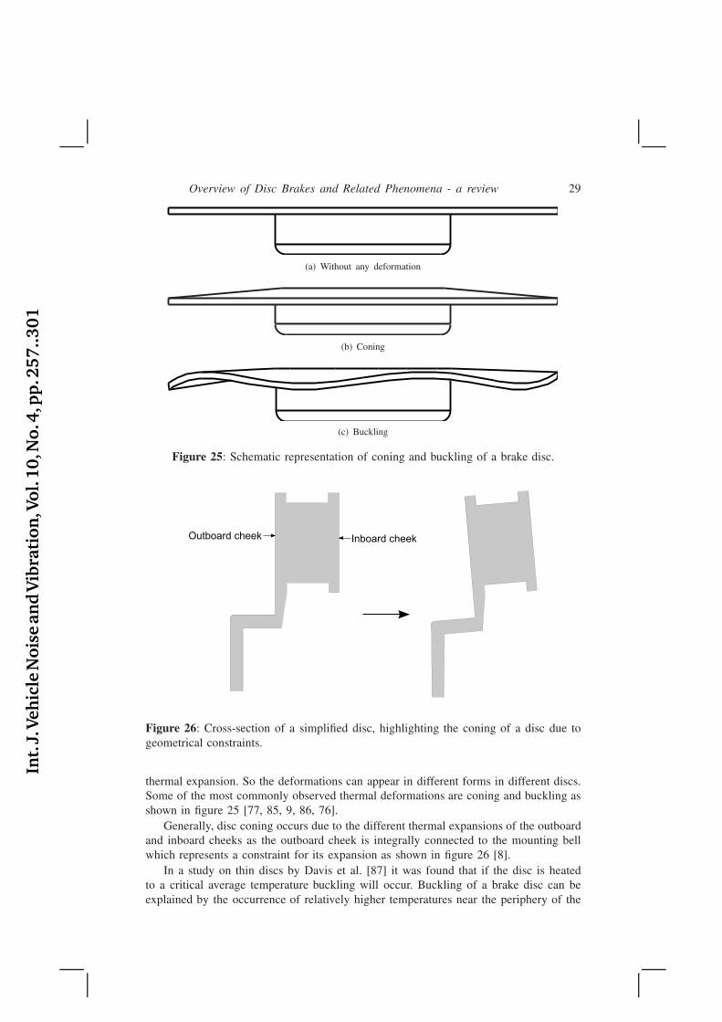
thermal expansion. So the deformations can appear in different forms in different discs.Some of the most commonly observed thermal deformations are coning and buckling asshown in figure 25 [77, 85, 9, 86, 76].
Generally, disc coning occurs due to the different thermal expansions of the outboardand inboard cheeks as the outboard cheek is integrally connected to the mounting bellwhich represents a constraint for its expansion as shown in figure 26 [8].
In a study on thin discs by Davis et al. [87] it was found that if the disc is heatedto a critical average temperature buckling will occur. Buckling of a brake disc can beexplained by the occurrence of relatively higher temperatures near the periphery of the
Int.
J.Veh
icle
Nois
ean
dV
ibra
tion
,Vol.
10,N
o.4
,pp
.257..301
30 A. Rashid
Figure 27: Schematic representation of different wavelengths for a brake disc.
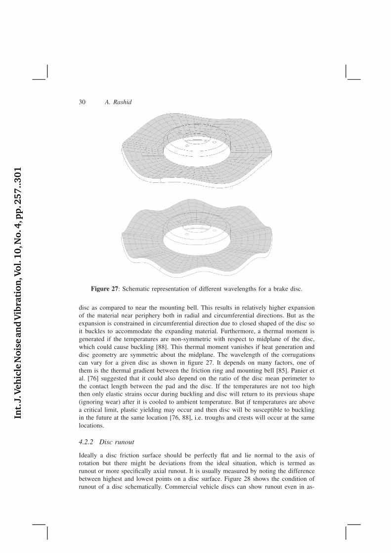
disc as compared to near the mounting bell. This results in relatively higher expansionof the material near periphery both in radial and circumferential directions. But as theexpansion is constrained in circumferential direction due to closed shaped of the disc soit buckles to accommodate the expanding material. Furthermore, a thermal moment isgenerated if the temperatures are non-symmetric with respect to midplane of the disc,which could cause buckling [88]. This thermal moment vanishes if heat generation anddisc geometry are symmetric about the midplane. The wavelength of the corrugationscan vary for a given disc as shown in figure 27. It depends on many factors, one ofthem is the thermal gradient between the friction ring and mounting bell [85]. Panier etal. [76] suggested that it could also depend on the ratio of the disc mean perimeter tothe contact length between the pad and the disc. If the temperatures are not too highthen only elastic strains occur during buckling and disc will return to its previous shape(ignoring wear) after it is cooled to ambient temperature. But if temperatures are abovea critical limit, plastic yielding may occur and then disc will be susceptible to bucklingin the future at the same location [76, 88], i.e. troughs and crests will occur at the samelocations.
4.2.2 Disc runout
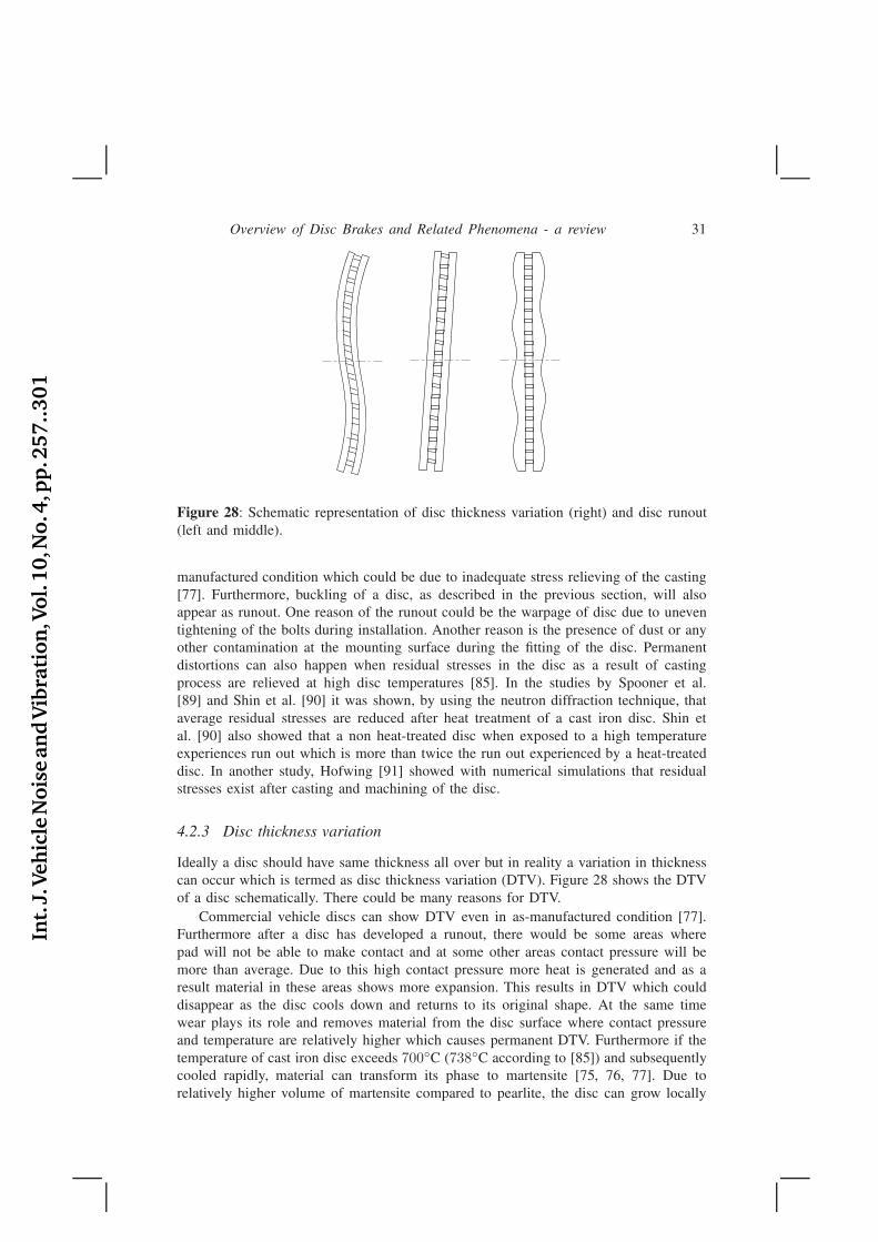
Ideally a disc friction surface should be perfectly flat and lie normal to the axis ofrotation but there might be deviations from the ideal situation, which is termed asrunout or more specifically axial runout. It is usually measured by noting the differencebetween highest and lowest points on a disc surface. Figure 28 shows the condition ofrunout of a disc schematically. Commercial vehicle discs can show runout even in as-
Int.
J.Veh
icle
Nois
ean
dV
ibra
tion
,Vol.
10,N
o.4
,pp
.257..301
Overview of Disc Brakes and Related Phenomena - a review 31
Figure 28: Schematic representation of disc thickness variation (right) and disc runout(left and middle).
manufactured condition which could be due to inadequate stress relieving of the casting[77]. Furthermore, buckling of a disc, as described in the previous section, will alsoappear as runout. One reason of the runout could be the warpage of disc due to uneventightening of the bolts during installation. Another reason is the presence of dust or anyother contamination at the mounting surface during the fitting of the disc. Permanentdistortions can also happen when residual stresses in the disc as a result of castingprocess are relieved at high disc temperatures [85]. In the studies by Spooner et al.[89] and Shin et al. [90] it was shown, by using the neutron diffraction technique, thataverage residual stresses are reduced after heat treatment of a cast iron disc. Shin etal. [90] also showed that a non heat-treated disc when exposed to a high temperatureexperiences run out which is more than twice the run out experienced by a heat-treateddisc. In another study, Hofwing [91] showed with numerical simulations that residualstresses exist after casting and machining of the disc.
4.2.3 Disc thickness variation
Ideally a disc should have same thickness all over but in reality a variation in thicknesscan occur which is termed as disc thickness variation (DTV). Figure 28 shows the DTVof a disc schematically. There could be many reasons for DTV.
Commercial vehicle discs can show DTV even in as-manufactured condition [77].Furthermore after a disc has developed a runout, there would be some areas wherepad will not be able to make contact and at some other areas contact pressure will bemore than average. Due to this high contact pressure more heat is generated and as aresult material in these areas shows more expansion. This results in DTV which coulddisappear as the disc cools down and returns to its original shape. At the same timewear plays its role and removes material from the disc surface where contact pressureand temperature are relatively higher which causes permanent DTV. Furthermore if thetemperature of cast iron disc exceeds 700◦C (738◦C according to [85]) and subsequentlycooled rapidly, material can transform its phase to martensite [75, 76, 77]. Due torelatively higher volume of martensite compared to pearlite, the disc can grow locally
Int.
J.Veh
icle
Nois
ean
dV
ibra
tion
,Vol.
10,N
o.4
,pp
.257..301
32 A. Rashid
Figure 29: Simplified representation of the convex bending of a pad.
which leads to DTV and remains even after cooling. Development of an uneven transferfilm on the disc surface can also contribute to the DTV.
4.2.4 Thermal deformation of pad
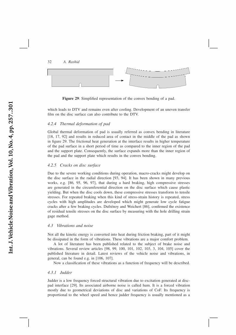
Global thermal deformation of pad is usually referred as convex bending in literature[18, 17, 92] and results in reduced area of contact in the middle of the pad as shownin figure 29. The frictional heat generation at the interface results in higher temperatureof the pad surface in a short period of time as compared to the inner region of the padand the support plate. Consequently, the surface expands more than the inner region ofthe pad and the support plate which results in the convex bending.
4.2.5 Cracks on disc surface
Due to the severe working conditions during operation, macro-cracks might develop onthe disc surface in the radial direction [93, 94]. It has been shown in many previousworks, e.g. [86, 95, 96, 97], that during a hard braking, high compressive stressesare generated in the circumferential direction on the disc surface which cause plasticyielding. But when the disc cools down, these compressive stresses transform to tensilestresses. For repeated braking when this kind of stress-strain history is repeated, stresscycles with high amplitudes are developed which might generate low cycle fatiguecracks after a few braking cycles. Dufrénoy and Weichert [86], confirmed the existenceof residual tensile stresses on the disc surface by measuring with the hole drilling straingage method.
4.3 Vibrations and noise
Not all the kinetic energy is converted into heat during friction braking, part of it mightbe dissipated in the form of vibrations. These vibrations are a major comfort problem.
A lot of literature has been published related to the subject of brake noise andvibrations. Several review articles [98, 99, 100, 101, 102, 103, 3, 104, 105] cover thepublished literature in detail. Latest reviews of the vehicle noise and vibrations, ingeneral, can be found e.g. in [106, 107].
Now a classification of these vibrations as a function of frequency will be described.
4.3.1 Judder
Judder is a low frequency forced structural vibration due to excitation generated at disc-pad interface [29]. Its associated airborne noise is called hum. It is a forced vibrationmostly due to geometrical deviations of disc and variations of CoF. Its frequency isproportional to the wheel speed and hence judder frequency is usually mentioned as a
Int.
J.Veh
icle
Nois
ean
dV
ibra
tion
,Vol.
10,N
o.4
,pp
.257..301
Overview of Disc Brakes and Related Phenomena - a review 33
multiple of wheel speed e.g. second-order judder means the judder frequency which istwice the revolutions per second of the wheel. The upper limit of its frequency dependson the maximum wheel speed and judder order (usually < 1000 [Hz]). Judder vibrationsare transmitted to the vehicle body and can be felt by driver in the brake pedal, steeringwheel or floor.
Hot judder
Hot judder, also called thermal judder, can be defined as the judder due to thermal cause.In other words it is generated due to temporary geometrical deviations of a disc astemperature goes higher and will disappear with disappearance of geometrical deviationsas the disc cools down. It is caused due to high thermal input to the brake in a shortperiod of time that results in a thermoelastic deformation, and eventually thermoelasticinstabilities in the form of hot spots [108].
Cold judder
It occurs due to permanent geometrical irregularities of the disc. So it can happen evenat the start of brake application when the disc is cold.
Normally judder consists of both hot and cold judder [29]. So it is difficult toseparate them and hence these classification could cause confusion.
4.3.2 Groan
Groan is a low frequency structural vibration. Its associated airborne noise is calledmoan. It occurs primarily as a result of friction characteristics of friction pair. Itsfrequency is generally independent of wheel speed and temperature [19]. It is usuallydivided in two categories, creep groan and dynamic groan. Creep groan is related tostick-slip motion and caused by a higher dynamic CoF than static CoF. Dynamic groanis an instability phenomenon as a result of friction-velocity characteristic known asnegative damping.
4.3.3 Squeal
Squeal is a high frequency (> 1000 [Hz] [3]) vibration of the brake components duringa braking action, primarily caused by resonance [29]. It results in a noise which is anuisance to passers-by and vehicle occupants. The vibrations propagate through the airrather than through the vehicle structure [29]. The most significant complication in bakesqueal research is its fugitive nature, i.e. brake squeal can sometimes be non-repeatable[103].
A braking system can squeal at a number of distinct frequencies which oftencorrespond to the natural frequencies of brake system components [3]. More precisely,squeal occurs in well-determined narrow frequency ranges because of changingconditions, e.g. temperature and pressure, may change the modal behavior of the brakecomponents [24]. These frequencies are independent of the speed of the vehicle butremain constant for a given brake system [24].
Brake squeal is a complex phenomenon. There has been significant progress towardsunderstanding the mechanism causing the generation of brake squeal but there is yeta lack of complete understanding of the causes of squeal noise [109]. Today, it is
Int.
J.Veh
icle
Nois
ean
dV
ibra
tion
,Vol.
10,N
o.4
,pp
.257..301
34 A. Rashid
commonly accepted in the disc brake community that squeal is initiated by an instabilitydue to the friction forces leading to self-excited vibrations [110]. Several explanationshave been proposed about the onset of instability. These could be categorized as
1. Decreasing µk with increasing vt
It has been proposed that a necessary condition for the onset of instability is thedecrease of µk with increasing vt. This school of thought is based on the work ofMills [111].
2. Sprag-slip
It proposes that the squeal occurs due to unstable oscillation in the system whicharises with the variation of friction force as a result of variation of the normal force.So this theory can be applied even when CoF is constant. This school of thoughtis based on the work of Spurr [112] and has been extended in other works e.g.[113, 114, 115].
Historically, to simplify the modelling of disc brakes, contact forces have notbeen considered as a moving load due to the low rotational speed of disc [104].This moving load acts at different locations at different times which could causean instability resulting in squeal even if the force itself is constant. Ouyanget al. considered the contact forces as a moving load in many of their works[116, 117, 118]. Cao et al. [119] modelled the brake squeal as a moving loadproblem and predicted unstable frequencies which were in a good agreement withthe experimentally found frequencies.
3. Modal coupling
It proposes that squeal is the consequence of the unstable resonances induced bythe friction force between disc and pads. This theory suggests that squeal is drivenby coupling of modes of the brake system components that are close in frequency.This explanation is based on the work of North [120, 98].
4. Hammering
It proposes that repeated impacts of a pad on a disc can excite it into a state ofvibration. These impacts could be as a result of rocking of pads due to geometricaldeviations of a disc. This explanation was proposed by Rhee et al. [121]. It isreported in [3] that sanding the surfaces of a disc is considered a remedy of brakesqueal which could be explained with the hammering theory as sanding reduces thegeometrical deviations and makes surface smoother. It is also reported in [122] thatpads with many small plateaus generate more squeal than do pads with few largeplateaus, which could be related to hammering theory [3].
Nowadays decreasing µk with increasing vt and sprag-slip are no more consideredthe actual mechanism exciting the squeal [3, 109].
A considerable amount of literature has been published on brake squeal. Researchershave used different experimental and computational techniques to understand thephenomenon of squeal. Early attempts to understand the phenomenon of squeal usingcomputational techniques has been through the development of few degrees of freedommodels, called minimal models or lumped parameter models. These models have beenreviewed in [3, 110, 105]. Recently finite element method, which results in models with
Int.
J.Veh
icle
Nois
ean
dV
ibra
tion
,Vol.
10,N
o.4
,pp
.257..301
Overview of Disc Brakes and Related Phenomena - a review 35
high number of degrees of freedom, has become popular. In contrast to minimal models,the finite element method has the advantage for accurate representation of the complexgeometries and boundary conditions. One of the earlier use of finite element methodwas to determine the modes and natural frequencies of brake discs [3].
Simulation and analysis methods are divided in two main categories: complexeigenvalue analysis and transient analysis [104]. The complex eigenvalue analysis studiesthe brake system at static steady sliding states and is mainly used to predict squealfrequencies. This was initially used on minimal models and later it was extended to finiteelement models [123]. A transient analysis is used to determine self-excited vibrationsduring the squeal event [124]. A transient analysis can take into account the time-dependent loads and other non-linearities. Complex eigenvalue analysis has been used bymany authors to predict the onset of instability which is considered the cause of squeal[125]. During the squeal vibrations, nonlinear effects can not be ignored and hence atransient analysis is required. It is reported in [124] that during transient vibrations, anadditional unstable mode can appear which is not predicted by the complex eigenvalueanalysis.
Study of brake squeal requires the consideration of many complex phenomenaand parameters e.g. contact evolution at disc-pad interface, wear, material propertieswhich are mostly temperature dependent and load/boundary conditions etc. Furthermoredue to manufacturing tolerances/variations of different parts could show inconsistentcharacteristics. This complexity presents a major difficulty for investigation of brakesqueal problem as repeatability of measurements during an experimental study becomesa major issue [109]. Modelling of such a complex system and correlating the computedresults to the measurements then becomes a challenging task. There is no validatedpredictive model of friction induced vibration to date [126]. It has been suggestedthat a brake system is highly sensitive to uncertainties [127]. The study of sensitivityin disc-pad systems is now attracting the attention of research community (see e.g.[128, 129, 126, 130, 127]). In [131], to take the uncertainties into account, descriptivestatistical analysis tools were used. In [132], brake squeal was treated as a chaoticphenomenon.
In an effort to avoid the complexity of a commercial brake system, researchers havealso developed the simplified test rigs. Less complicated geometry of a simplified set-upalso requires a simple model which ultimately reduces the uncertainties. Simplified set-ups can be classified into pin-on-disc systems (e.g. [133, 134] ), beam-on-disc (e.g. [135,136] ), laboratory brake (e.g. [137, 138]) and tribo brake (e.g. [125, 139] ). These set-ups (except pin-on-disc) are reviewed and described in [109]. A chronological overviewof simplified set-ups is given in [132]. In the opinion of Akay et al. [109], the advancestowards the understanding of underlying mechanism of squeal has been mostly due tothe simplified set-ups as the repeatable squeal conditions become possible and in parallelfinite element models verified these results, at least qualitatively.
Structural damping has been shown to be of primary importance to the stabilityof mode couplings [140, 141, 142, 143]. Effects of damping have been considered onminimal models in many studies (see e.g. [144, 140, 141, 145]) but mostly ignoredin finite element models due to complexity [123]. Fritz et al. [123] developed a finiteelement model of a brake system and showed that damping does not always stabilizesthe brake system instead it could also make the system unstable depending upon themodes involved.
Int.
J.Veh
icle
Nois
ean
dV
ibra
tion
,Vol.
10,N
o.4
,pp
.257..301
36 A. Rashid
In their review, Kinkaid et al. [3] describe that it is a common belief that, toavoid squeal, the brake pads, disc and caliper are designed in a way that theirnatural frequencies in the audible range are as isolated as possible. However theyalso mention that this is not sufficient as there are cases reported in literature wheresquealing frequencies depend only on the disc brake rotor and are independent ofother components in a brake system. It was also demonstrated in [146] that effects ofstructural damping on mode coupling instability must be taken into account to avoiddesign errors. Structural modifications of components of a disc brake system have beenused by many researchers to change their modal characteristics. Many disc modificationse.g. cheek thickness, vanes shape and size, and drilled holes have been proposed tosuppress squeal [147]. Modification of brake pads such as chamfers and slots can alsohelp to reduce squeal noise [14, 15, 16]. It was explained in [148] that chamferingcould modify the merging behaviour of the modes and thus reduce squeal. It hasbeen proposed that breaking the symmetry of brake disc could be a countermeasureto squeal [149, 150, 151]. In [151] it is shown that asymmetry of a disc results insplitting the double modes and has a stabilizing effect. This knowledge has been usedin [152, 153, 154] for optimization of the brake rotor to avoid squeal.
Another solution to suppress squeal is the use of laminated shims which are attachedto the back plate of brake pad. These shims increase system modal damping whichreduces the propensity for squeal noise [24].
4.3.4 Wire brush
It is a superposition of high frequency oscillation with randomly varying amplitude [19].It is also called roughness noise. It is a structural-borne noise and not the air-borne[155].
5 Conclusions
Disc brake is a complex system and understanding different issues related to its designand operation require expertise from different disciplines e.g. tribology, material science,fluid dynamics, vibrations etc. Disc brakes have evolved a lot over the decades due toextensive research and development. There are still many phenomenon which are notunderstood fully.
For realistic computational analysis of disc brake systems, it is crucial to furtherdevelop non-linear finite element models which could simulate realistic evolution ofcontact interface. Such models should be capable, atleast, to incorporate a realisticfriction and wear model, and temperature dependent material properties.
One of the issue which has attracted a lot of attention of research community is thebrake squeal. Due to continuous development of disc brake systems, they have becomequieter although squeal problem has not been solved well [3, 119, 132]. The problemof predicting the brake squeal propensity remains a challenging task for brake researchcommunity [131].
Int.
J.Veh
icle
Nois
ean
dV
ibra
tion
,Vol.
10,N
o.4
,pp
.257..301
Overview of Disc Brakes and Related Phenomena - a review 37
6 Acknowledgement
This project was financed by Vinnova (FFI-Strategic Vehicle Research and Innovation)and Volvo 3P.
References
[1] P. Lingman. Integrated brake control downhill driving strategies. PhD thesis,Chalmers Tekniska Hogskola, 2006.
[2] C. Owen. Automotive Brake Systems, Classroom Manual. Today’s Technician.Delmar Cengage Learning, 2010.
[3] N. M. Kinkaid, O. M. O’Reilly, and P. Papadopoulos. Automotive disc brakesqueal. Journal of Sound and Vibration, 267(1):105–166, 2003.
[4] H. Keller. Brake disc, particularly an internally ventilated brake disc, June 282011. US Patent 7,967,115.
[5] M. Franke. Brake disc, October 6 2009. US Patent Application 12/574,189.
[6] A. Giorgetti. Disc for a disc brake for vehicles in general and for high-performance cars in particular, November 28 2000. US Patent 6,152,270.
[7] T. Deichmann and H. Lathwesen. Sheet cast disc-brake disc innovation throughfunctional integration. Proceedings of the Eurobrake, 16-18 April, Dresden,
Germany, 2012.
[8] S. Koetniyom. Thermal Stress Analysis of Automotive Disc Brakes. PhD thesis,University of Leeds, 2000.
[9] S. Koetniyom, P.C. Brooks, and D.C. Barton. The development of a materialmodel for cast iron that can be used for brake system analysis. Proceedings of the
Institution of Mechanical Engineers, Part D: Journal of Automobile Engineering,216(5):349–362, 2002.
[10] L. Wallis, E. Leonardi, B. Milton, and P. Joseph. Air flow and heat transfer inventilated disc brake rotors with diamond and tear-drop pillars. Numerical Heat
Transfer; Part A: Applications, 41(6-7):643–655, 2002.
[11] E. Palmer, R. Mishra, and J. Fieldhouse. An optimization study of a multiple-row pin-vented brake disc to promote brake cooling using computational fluiddynamics. Proceedings of the Institution of Mechanical Engineers, Part D:
Journal of Automobile Engineering, 223(7):865–875, 2009.
[12] J. Hulten and I. Dagh. Brake disc for a vehicle disc brake, August 29 2006. USPatent 7,097,010.
[13] M. Duzgun. Investigation of thermo-structural behaviors of different ventilationapplications on brake discs. Journal of Mechanical Science and Technology,26(1):235–240, 2012.
Int.
J.Veh
icle
Nois
ean
dV
ibra
tion
,Vol.
10,N
o.4
,pp
.257..301
38 A. Rashid
[14] S.C. Lin, C.C. Guan, A.R.A. Bakar, M.R. Jamaluddin, M.M.W. Wan Harujan, andB.A. Ghani. Disc brake squeal suppression through chamfered and slotted pad.International Journal of Vehicle Structures and Systems, 3(1):28–35, 2011.
[15] Y. Dai and T.C. Lim. Suppression of brake squeal noise applying finite elementbrake and pad model enhanced by spectral-based assurance criteria. Applied
Acoustics, 69(3):196 – 214, 2008.
[16] N.M. Ghazaly and W.F. Faris. Optimal design of a brake pad for squeal noisereduction using response surface methodology. International Journal of Vehicle
Noise and Vibration, 8(2):125–135, 2012.
[17] M. Eriksson, F. Bergman, and S. Jacobson. On the nature of tribological contactin automotive brakes. Wear, 252(1-2):26–36, 2002.
[18] K. Lee and J.R. Barber. An experimental investigation of frictionally-excitedthermoelastic instability in automotive disk brakes under a drag brake application.Journal of Tribology, 116(3):409–414, 1994.
[19] M. B. Hiller. Correlation between parameters of the tribosystem and automotive
disc brake squeal. PhD thesis, University of Paderborn, 2006.
[20] L. Matozo, A. Menetrier, and A. Tamagna. Analysis of high damping underlayermaterials for brake pads and its effects on NVH performance. SAE Technical
Paper, pages 01–3223, 2006.
[21] Automotive Disc Brake Manual: The Complete Guide to the Theory and Practice
of Automotive Disc Braking Systems. Techbook Series. Haynes, Somerset, 1998.
[22] N. Pham. Backing plate with friction material retention members and method andapparatus for manufacturing same, May 29 2007. US Patent 7,222,701.
[23] M. Uwaydah. Brake pad backing plate and method of making the same, January23 2004. US Patent App. 10/763,607.
[24] A.M. Balvedi and S.N.Y. Gerges. Squeal noise in disc brakes and the influenceof damping on the system dynamic stability. Acta Acustica united with Acustica,94(2):254–264, 2008.
[25] A.R. AbuBakar and H. Ouyang. Wear prediction of friction material and brakesqueal using the finite element method. Wear, 264(11-12):1069–1076, 2008.
[26] G. Cueva, A. Sinatora, W.L. Guesser, and A.P. Tschiptschin. Wear resistance ofcast irons used in brake disc rotors. Wear, 255(7-12):1256–1260, 2003.
[27] R. Thornton, T. Slatter, A.H. Jones, and R. Lewis. The effects of cryogenicprocessing on the wear resistance of grey cast iron brake discs. Wear, 271(9-10):2386–2395, 2011.
[28] S. Bickerstaffe. Weight savings all round. Automotive Engineer (London),32(10):20–21, 2007.
Int.
J.Veh
icle
Nois
ean
dV
ibra
tion
,Vol.
10,N
o.4
,pp
.257..301
Overview of Disc Brakes and Related Phenomena - a review 39
[29] H. Jacobsson. Aspects of disc brake judder. Proceedings of the Institution of
Mechanical Engineers, Part D: Journal of Automobile Engineering, 217(6):419–430, 2003.
[30] O. Maluf, M. Angeloni, D.B.V. Castro, W.W. Bose Filho, D. Spinelli, and C.O.F.T.Ruckert. Effect of alloying elements on thermal diffusivity of gray cast iron usedin automotive brake disks. Journal of Materials Engineering and Performance,18(7):980–984, 2009.
[31] A.A. Adebisi, M. Maleque, and MM Rahman. Metal matrix composite brakerotor: Historical development and product life cycle analysis. International
Journal of Automotive and Mechanical Engineering, 4(1):471–480, 2011.
[32] S.W. Kim, K. Park, S.H. Lee, K.H. Kang, and K.T. Lim. Thermophysicalproperties of automotive metallic brake disk materials. International Journal of
Thermophysics, 29(6):2179–2188, 2008.
[33] H. Nakanishi, K. Kakihara, A. Nakayama, and T. Murayama. Development ofaluminum metal matrix composites (Al-MMC) brake rotor and pad. JSAE Review,23(3):365–370, 2002.
[34] R. Renz, G. Seifert, and W. Krenkel. Integration of CMC brake disks inautomotive brake systems. International Journal of Applied Ceramic Technology,9(4):712–724, 2012.
[35] W. Krenkel, B. Heidenreich, and R. Renz. C/C-SiC composites for advancedfriction systems. Advanced Engineering Materials, 4(7):427–436, 2002.
[36] Ch. Zuber and B. Heidenreich. Development of a net shape manufacturingmethod for ventilated brake discs in single piece design. Materialwissenschaft
und Werkstofftechnik, 37(4):301–308, 2006.
[37] G.P. Ostermeyer and M. Müller. New insights into the tribology of brakesystems. Proceedings of the Institution of Mechanical Engineers, Part D: Journal
of Automobile Engineering, 222(7):1167–1200, 2008.
[38] W. Österle, I. Dörfel, C. Prietzel, H. Rooch, A.-L. Cristol-Bulthé, G. Degallaix,and Y. Desplanques. A comprehensive microscopic study of third body formationat the interface between a brake pad and brake disc during the final stage of apin-on-disc test. Wear, 267(5-8):781–788, 2009.
[39] D. Chan and G.W. Stachowiak. Review of automotive brake friction materials.Proceedings of the Institution of Mechanical Engineers, Part D: Journal of
Automobile Engineering, 218(9):953–966, 2004.
[40] U.S. Hong, S.L. Jung, K.H. Cho, M.H. Cho, S.J. Kim, and H. Jang. Wearmechanism of multiphase friction materials with different phenolic resin matrices.Wear, 266(7-8):739 – 744, 2009.
[41] Z. Fu, B. Suo, R. Yun, Y. Lu, H. Wang, S. Qi, S. Jiang, Y. Lu, and V. Matejka.Development of eco-friendly brake friction composites containing flax fibers.Journal of Reinforced Plastics and Composites, 31(10):681–689, 2012.
Int.
J.Veh
icle
Nois
ean
dV
ibra
tion
,Vol.
10,N
o.4
,pp
.257..301
40 A. Rashid
[42] H. Jang, K. Ko, S.J. Kim, R.H. Basch, and J.W. Fash. The effect of metal fiberson the friction performance of automotive brake friction materials. Wear, 256(3-4):406 – 414, 2004.
[43] H.A. Kemmer. Investigation of the Friction Behavior of Automotive Brakes
Through Experiments and Tribological Modeling. PhD thesis, UniversitatPaderborn, 2002.
[44] P.J. Blau. Compositions, functions, and testing of friction brake materials andtheir additives. Technical Report No. ORNL/TM-2001/64, Oak Ridge NationalLab., TN (US), 2001.
[45] M. Eriksson and S. Jacobson. Tribological surfaces of organic brake pads.Tribology International, 33(12):817–827, 2000.
[46] B. Bhushan. Contact mechanics of rough surfaces in tribology: Multiple asperitycontact. Tribology Letters, 4(1):1–35, 1998.
[47] M. Nosonovsky and B. Bhushan. Multiscale friction mechanisms and hierarchicalsurfaces in nano- and bio-tribology. Materials Science and Engineering: R:
Reports, 58(3-5):162 – 193, 2007.
[48] H. Dankowicz. On the modeling of dynamic friction phenomena. ZAMM
Zeitschrift fur Angewandte Mathematik und Mechanik, 79(6):399–409, 1999.
[49] J.T. Oden and J.A.C. Martins. Models and computational methods for dynamicfriction phenomena. Computer Methods in Applied Mechanics and Engineering,52(1-3):527–634, 1985.
[50] J. Takadoum. Materials and Surface Engineering in Tribology. ISTE Wiley,London, UK., 2010.
[51] H.C. Meng and K.C. Ludema. Wear models and predictive equations: their formand content. Wear, 181-183, Part 2:443 – 457, 1995.
[52] A. Saffar, A. Shojaei, and M. Arjmand. Theoretical and experimental analysisof the thermal, fade and wear characteristics of rubber-based composite frictionmaterials. Wear, 269(1-2):145 – 151, 2010.
[53] S.M. Hsu, M.C. Shen, and A.W. Ruff. Wear prediction for metals. Tribology
International, 30(5):377 – 383, 1997.
[54] J.F. Archard. Contact and rubbing of flat surfaces. Journal of Applied Physics,24(8):981–988, 1953.
[55] J. F. Archard and W. Hirst. The wear of metals under unlubricated conditions.Proceedings of the Royal Society of London. Series A, Mathematical and Physical
Sciences, 236(1206):397–410, 1956.
[56] W. Österle and A.I. Dmitriev. Functionality of conventional brake frictionmaterials - perceptions from findings observed at different length scales. Wear,271(9-10):2198–2207, 2011.
Int.
J.Veh
icle
Nois
ean
dV
ibra
tion
,Vol.
10,N
o.4
,pp
.257..301
Overview of Disc Brakes and Related Phenomena - a review 41
[57] W. Österle and I. Urban. Third body formation on brake pads and rotors.Tribology International, 39(5):401–408, 2006.
[58] W. Österle and Urban I. Friction layers and friction films on PMC brake pads.Wear, 257(1-2):215 – 226, 2004.
[59] W. Österle, M. Griepentrog, Th. Gross, and I. Urban. Chemical andmicrostructural changes induced by friction and wear of brakes. Wear, 250-251(1-12):1469–1476, 2001.
[60] P. Filip, Z. Weiss, and D. Rafaja. On friction layer formation in polymer matrixcomposite materials for brake applications. Wear, 252(3):189–198, 2002.
[61] A. Wirth, D. Eggleston, and R. Whitaker. A fundamental tribochemical study ofthe third body layer formed during automotive friction braking. Wear, 179(1-2):75– 81, 1994.
[62] D. Severin and S. Dörsch. Friction mechanism in industrial brakes. Wear,249(9):771–779, 2001.
[63] M. Eriksson, J. Lord, and S. Jacobson. Wear and contact conditions of brakepads: Dynamical in situ studies of pads on glass. Wear, 249(3-4):272–278, 2001.
[64] W. Österle, H. Kloß, I. Urban, and A.I. Dmitriev. Towards a better understandingof brake friction materials. Wear, 263(7-12):1189–1201, 2007.
[65] M.H. Cho, K.H. Cho, S.J. Kim, D.H. Kim, and H. Jang. The role of transferlayers on friction characteristics in the sliding interface between friction materialsagainst gray iron brake disks. Tribology Letters, 20(2):101–108, 2005.
[66] S.K. Rhee, M.G. Jacko, and P.H.S. Tsang. The role of friction film in friction,wear and noise of automotive brakes. Wear, 146(1):89–97, 1991.
[67] A. Heussaff, L. Dubar, T. Tison, M. Watremez, and R.F. Nunes. A methodologyfor the modelling of the variability of brake lining surfaces. Wear, 289:145–159,2012.
[68] M. Eriksson. Friction and contact phenomena of disc brakes related to squeal.PhD thesis, Uppsala University, Department of Materials Science, 2000.
[69] P.J. Blau and J.C. McLaughlin. Effects of water films and sliding speed onthe frictional behavior of truck disc brake materials. Tribology International,36(10):709 – 715, 2003.
[70] S.K. Rhee. Friction properties of a phenolic resin filled with iron and graphite -sensitivity to load, speed and temperature. Wear, 28(2):277–281, 1974.
[71] M.H. Cho, S.J. Kim, R.H. Basch, J.W. Fash, and H. Jang. Tribological study ofgray cast iron with automotive brake linings: The effect of rotor microstructure.Tribology International, 36(7):537–545, 2003.
[72] M.H. Cho, S.J. Kim, D. Kim, and H. Jang. Effects of ingredients on tribologicalcharacteristics of a brake lining: An experimental case study. Wear, 258(11-12):1682–1687, 2005.
Int.
J.Veh
icle
Nois
ean
dV
ibra
tion
,Vol.
10,N
o.4
,pp
.257..301
42 A. Rashid
[73] N.S.M. EL-Tayeb and K.W. Liew. On the dry and wet sliding performance ofpotentially new frictional brake pad materials for automotive industry. Wear,266(1-2):275 – 287, 2009.
[74] K.W. Liew and U. Nirmal. Frictional performance evaluation of newly designedbrake pad materials. Materials & Design, 48:25–33, 2013.
[75] J.R. Barber. Thermoelastic instabilities in the sliding of conforming solids. Proc.
R. Soc. London, 312:381–394, 1969.
[76] S. Panier, P. Dufrénoy, and D. Weichert. An experimental investigation of hotspots in railway disc brakes. Wear, 256(7-8):764–773, 2004.
[77] T.K. Kao, J.W. Richmond, and A. Douarre. Brake disc hot spotting and thermaljudder: an experimental and finite element study. International Journal of Vehicle
Design, 23(3):276–296, 2000.
[78] D. Thuresson. Influence of material properties on sliding contact brakingapplications. Wear, 257(5-6):451 – 460, 2004.
[79] K. H. Bode and G.P. Ostermeyer. Simulations and tests of innovative friction lawsin brake systems. PAMM, 9(1):63–66, 2010.
[80] T. Vernersson and R. Lundén. Wear of block brakes and disc brakes for repeatedbrake cycles. In Proceedings 6th European Conference on Braking (JEF2010,
Lille, France), pages 19–27, 24-25 November 2010.
[81] A. Söderberg and S. Andersson. Simulation of wear and contact pressuredistribution at the pad-to-rotor interface in a disc brake using general purposefinite element analysis software. Wear, 267(12):2243–2251, 2009.
[82] S.K. Rhee. Wear equation for polymers sliding against metal surfaces. Wear,16(6):431 – 445, 1970.
[83] J. M. Herring. Mechanism of brake fade in organic brake linings. Society of
Automotive Engineers, (Paper No. 670146), 1967.
[84] B.K. Satapathy and J. Bijwe. Performance of friction materials based on variationin nature of organic fibres: Part I. Fade and recovery behaviour. Wear, 257(5-6):573 – 584, 2004.
[85] D. Eggleston. An investigation into frictional surface interactions and their effect
on brake judder. PhD thesis, Sheffield Hallam University, 2000.
[86] P. Dufrénoy and D. Weichert. A thermomechanical model for the analysis of discbrake fracture mechanisms. Journal of Thermal Stresses, 26(8):815–828, 2003.
[87] C.L. Davis, C.M. Krousgrill, and F. Sadeghi. Effect of temperature onthermoelastic instability in thin disks. Journal of Tribology, 124(3):429–437,2002.
[88] S. Panier, P. Dufrénoy, J.F. Brunel, and D. Weichert. Progressive wavinessdistortion: A new approach of hot spotting in disc brakes. Journal of Thermal
Stresses, 28(1):47–62, 2005.
Int.
J.Veh
icle
Nois
ean
dV
ibra
tion
,Vol.
10,N
o.4
,pp
.257..301
Overview of Disc Brakes and Related Phenomena - a review 43
[89] S. Spooner, E.A. Payzant, and C. R. Hubbard. Neutron scattering residual stressmeasurements on gray cast iron brake discs. Technical report, Oak Ridge NationalLab., TN (United States), 1996.
[90] M.W. Shin, G.H. Jang, J.K. Kim, H.Y. Kim, and H. Jang. The effect of residualstress on the distortion of gray iron brake disks. Journal of Materials Engineering
and Performance, 22(4):1129–1135, 2013.
[91] M. Hofwing. Robustness of residual stresses in brake discs by metamodeling. InProceedings of the ASME Design Engineering Technical Conference, volume 5,pages 1115–1125, 2011.
[92] A. Rashid and N. Strömberg. Thermomechanical simulation of wear and hot bandsin a disc brake by adopting an eulerian approach. EuroBrake, Dresden, Germany,
June 17-19, 2013.
[93] D.J. Kim, Y.M. Lee, J.S. Park, and C.S. Seok. Thermal stress analysis for adisk brake of railway vehicles with consideration of the pressure distribution on africtional surface. Materials Science and Engineering A, 483-484(1-2 C):456–459,2008.
[94] F. Bagnoli, F. Dolce, and M. Bernabei. Thermal fatigue cracks of fire fightingvehicles gray iron brake discs. Engineering Failure Analysis, 16(1):152–163,2009.
[95] C. Gao, J.M. Huang, X.Z. Lin, and X.S.C. Tang. Stress analysis of thermal fatiguefracture of brake disks based on thermomechanical coupling. Journal of Tribology,129(3):536–543, 2007.
[96] T.J. Mackin, S.C. Noe, K.J. Ball, B.C. Bedell, et al. Thermal cracking in discbrakes. Engineering Failure Analysis, 9(1):63–76, 2002.
[97] A. Rashid and N. Strömberg. Sequential simulation of thermal stresses indisc brakes for repeated braking. Proceedings of the Institution of Mechanical
Engineers, Part J: Journal of Engineering Tribology, 227(8):919–929, 2013.
[98] M.R. North. Disc brake squeal. Braking of Road Vehicles, Automobile Division of
the Institution of Mechanical Engineers, Mechanical Engineeering Publications,(76):169–176, 1976.
[99] M. Nishiwaki. Review of study on brake squeal. JSAE Review, 11(4):48–54,1990.
[100] D.A. Crolla and A.M. Lang. Brake noise and vibration - the state of the art.Tribology Series, 18(C):165–174, 1991.
[101] R.A. Ibrahim. Friction-induced vibration, chatter, squeal, and chaos, part i:Mechanics of contact and friction. Appl. Mech. Rev., 47(7):209–226, 1994.
[102] S. Yang and R.F. Gibson. Brake vibration and noise: Reviews, comments, andproposals. International Journal of Materials and Product Technology, 12(4-6):496–513, 1997.
Int.
J.Veh
icle
Nois
ean
dV
ibra
tion
,Vol.
10,N
o.4
,pp
.257..301
44 A. Rashid
[103] A. Papinniemi, J.C.S. Lai, J. Zhao, and L. Loader. Brake squeal: A literaturereview. Applied Acoustics, 63(4):391–400, 2002.
[104] Huajiang Ouyang, Wayne Nack, Yongbin Yuan, and Frank Chen. Numericalanalysis of automotive disc brake squeal: a review. International Journal of
Vehicle Noise and Vibration, 1(3):207–231, 2005.
[105] C. Cantoni, R. Cesarini, G. Mastinu, G. Rocca, and R. Sicigliano. Brake comfort- a review. Vehicle System Dynamics, 47(8):901–947, 2009.
[106] M.S. Qatu, M.K. Abdelhamid, J. Pang, and G. Sheng. Overview of automotivenoise and vibration. International Journal of Vehicle Noise and Vibration, 5(1-2):1–35, 2009.
[107] M.S. Qatu. Recent research on vehicle noise and vibration. International Journal
of Vehicle Noise and Vibration, 8(4):289–301, 2012.
[108] D. Bryant, J. Fieldhouse, A. Crampton, C. Talbot, and J. Layfield. Thermal brakejudder investigations using a high speed dynamometer. SAE Technical Paper 2008-
01-0818, 2008.
[109] A. Akay, O. Giannini, F. Massi, and A. Sestieri. Disc brake squeal characterizationthrough simplified test rigs. Mechanical Systems and Signal Processing,23(8):2590–2607, 2009.
[110] Utz von Wagner, D. Hochlenert, and P. Hagedorn. Minimal models for disk brakesqueal. Journal of Sound and Vibration, 302(3):527–539, 2007.
[111] H.R. Mills. Brake squeak. Technical Report 9000 B, Institution of Automobile
Engineers, 1938.
[112] R.T. Spurr. A theory of brake squeal. Proceedings of the Automobile Division,
Institution of Mechanical Engineers, 1(1):33–52, 1961-1962.
[113] R.P. Jarvis and B. Mills. Vibrations induced by dry friction. Proceedings of the
Institution of Mechanical Engineers, 178(32):847–866, 1963.
[114] S.W.E. Earles and G.B. Soar. Squeal noise in disc brakes. I Mech E Symposium
on Vibration and Noise in Motor Vehicles, 1971.
[115] N. Millner. An analysis of disc brake squeal. SAE Technical Paper 780332, 1978.
[116] H. Ouyang, J.E. Mottershead, and W. Li. Vibration and dynamic instability ofmoving load systems. In Proceedings of the 25th International Conference on
Noise and Vibration Engineering, pages 1377–1382, ISMA; Leuven; Belgium, 13-15 September 2000.
[117] H. Ouyang, Q. Cao, J.E. Mottershead, and T. Treyde. Vibration and squeal of adisc brake: Modelling and experimental results. Proceedings of the Institution of
Mechanical Engineers, Part D: Journal of Automobile Engineering, 217(10):867–875, 2003.
Int.
J.Veh
icle
Nois
ean
dV
ibra
tion
,Vol.
10,N
o.4
,pp
.257..301
Overview of Disc Brakes and Related Phenomena - a review 45
[118] H. Ouyang, J.E. Mottershead, and W. Li. A moving-load model for disc-brakestability analysis. Journal of Vibration and Acoustics, Transactions of the ASME,125(1):53–58, 2003.
[119] Q. Cao, H. Ouyang, M.I. Friswell, and J.E. Mottershead. Linear eigenvalueanalysis of the disc-brake squeal problem. International Journal for Numerical
Methods in Engineering, 61(9):1546–1563, 2004.
[120] M.R. North. Disc brake squeal - a theoretical model. Technical Report 1972/5,
Motor Industry Research Association, Warwickshire, England, 1972.
[121] S.K. Rhee, P.H.S. Tsang, and Y.S. Wang. Friction-induced noise and vibration ofdisc brakes. Wear, 133(1):39–45, 1989.
[122] M. Eriksson, F. Bergman, and S. Jacobson. Surface characterisation of brake padsafter running under silent and squealing conditions. Wear, 232(2):163–167, 1999.
[123] G. Fritz, J.-J. Sinou, J.-M. Duffal, and L. Jézéquel. Effects of damping on brakesqueal coalescence patterns - application on a finite element model. Mechanics
Research Communications, 34(2):181–190, 2007.
[124] J.-J. Sinou. Transient non-linear dynamic analysis of automotive disc brake squeal- on the need to consider both stability and non-linear analysis. Mechanics
Research Communications, 37(1):96–105, 2010.
[125] F. Massi, L. Baillet, O. Giannini, and A. Sestieri. Brake squeal: Linear andnonlinear numerical approaches. Mechanical Systems and Signal Processing,21(6):2374–2393, 2007.
[126] T. Butlin and J. Woodhouse. Sensitivity of friction-induced vibration in idealisedsystems. Journal of Sound and Vibration, 319(1-2):182–198, 2009.
[127] T. Butlin and J. Woodhouse. Friction-induced vibration: Quantifying sensitivityand uncertainty. Journal of Sound and Vibration, 329(5):509–526, 2010.
[128] D. Guan, X. Su, and F. Zhang. Sensitivity analysis of brake squeal tendency tosubstructures’ modal parameters. Journal of Sound and Vibration, 291(1-2):72–80,2006.
[129] J. Huang, C.M. Krousgrill, and A.K. Bajaj. Modeling of automotive drum brakesfor squeal and parameter sensitivity analysis. Journal of Sound and Vibration,289(1-2):245–263, 2006.
[130] T. Butlin and J. Woodhouse. Sensitivity studies of friction-induced vibration.International Journal of Vehicle Design, 51(1-2):238–257, 2009.
[131] S. Oberst and J.C.S. Lai. Statistical analysis of brake squeal noise. Journal of
Sound and Vibration, 330(12):2978–2994, 2011.
[132] S. Oberst and J.C.S. Lai. Chaos in brake squeal noise. Journal of Sound and
Vibration, 330(5):955–975, 2011.
Int.
J.Veh
icle
Nois
ean
dV
ibra
tion
,Vol.
10,N
o.4
,pp
.257..301
46 A. Rashid
[133] S.W.E. Earles and M.N.M. Badi. Oscillatory instabilities generated in a double-pin and disc undamped system: a mechanism of disc-brake squeal. Proceedings of
the Institution of Mechanical Engineers, Part C: Mechanical Engineering Science,198(4):43–50, 1984.
[134] W.W. Tworzydlo, O.N. Hamzeh, W. Zaton, and T.J. Judek. Friction-inducedoscillations of a pin-on-disk slider: Analytical and experimental studies. Wear,236(1-2):9–23, 1999.
[135] A. Akay, J.A. Wickert, and Z. Xu. Investigation of mode lock-in and frictioninterface, technical report. Final Report, Department of Mechanical Engineering,
CarnegieMellon University, 2000.
[136] A. Tuchinda, N.P. Hoffmann, D.J. Ewins, and W. Keiper. Mode lock-incharacteristics and instability study of the pin-on-disc system. Proceedings of the
International Modal Analysis Conference - IMAC, 1:71–77, 2001.
[137] O. Giannini and A. Sestieri. Predictive model of squeal noise occurring on alaboratory brake. Journal of Sound and Vibration, 296(3):583–601, 2006.
[138] O. Giannini and F. Massi. Characterization of the high-frequency squeal on alaboratory brake setup. Journal of Sound and Vibration, 310(1-2):394–408, 2008.
[139] F. Massi, O. Giannini, and L. Baillet. Brake squeal as dynamic instability:An experimental investigation. Journal of the Acoustical Society of America,120(3):1388–1398, 2006.
[140] N. Hoffmann and L. Gaul. Effects of damping on mode-coupling instability infriction induced oscillations. ZAMM Zeitschrift fur Angewandte Mathematik und
Mechanik, 83(8):524–534, 2003.
[141] K. Shin, M.J. Brennan, J.-E. Oh, and C.J. Harris. Analysis of disc brakenoise using a two-degree-of-freedom model. Journal of Sound and Vibration,254(5):837–848, 2002.
[142] J.-J. Sinou and L. Jézéquel. Mode coupling instability in friction-inducedvibrations and its dependency on system parameters including damping. European
Journal of Mechanics, A/Solids, 26(1):106–122, 2007.
[143] B. Hervé, J.-J. Sinou, H. Mahé, and L. Jézéquel. Analysis of squeal noise andmode coupling instabilities including damping and gyroscopic effects. European
Journal of Mechanics, A/Solids, 27(2):141–160, 2008.
[144] S.W.E. Earles and P.W. Chambers. Disc brake squeal noise generation: Predictingits dependency on system parameters including damping. International Journal of
Vehicle Design, 8(4-6):538–552, 1987.
[145] K. Shin, J.-E. Oh, and M.J. Brennan. Nonlinear analysis of friction inducedvibrations of a two-degree-of-freedom model for disc brake squeal noise. JSME
International Journal, Series C: Mechanical Systems, Machine Elements and
Manufacturing, 45(2):426–432, 2002.
Int.
J.Veh
icle
Nois
ean
dV
ibra
tion
,Vol.
10,N
o.4
,pp
.257..301
Overview of Disc Brakes and Related Phenomena - a review 47
[146] J.-J. Sinou and L. Jézéquel. Mode coupling instability in friction-inducedvibrations and its dependency on system parameters including damping. European
Journal of Mechanics, A/Solids, 26(1):106–122, 2007.
[147] S.C. Lin, A.R. AbuBakar, W.M.M.W. Harujan, et al. Suppressing disc brakesqueal through structural modifications. Jurnal Mekanikal, 29:67–83, 2009.
[148] H.V. Chowdhary, A.K. Bajaj, and C.M. Krousgill. An analytical approachto model disc brake system for squeal prediction. Proceedings of DETC’01,
DETC2001/VIB-21560, ASME, Pittsburgh, PA, pages 1–10, 2001.
[149] M. Nishiwaki, H. Harada, and H. Okamura. Study on disc brake squeal. SAE
Technical Paper 890864, 1989.
[150] J.D. Fieldhouse, W.P. Steel, C.J. Talbot, and M.A. Siddiqui. Rotor asymmetryused to reduce disk brake noise. SAE Technical Paper 2004-01-2797, 2004.
[151] G. Spelsberg-Korspeter. Breaking of symmetries for stabilization of rotatingcontinua in frictional contact. Journal of Sound and Vibration, 322(4-5):798–807,2009.
[152] G. Spelsberg-Korspeter. Structural optimization for the avoidance of self-excited vibrations based on analytical models. Journal of Sound and Vibration,329(23):4829–4840, 2010.
[153] G. Spelsberg-Korspeter. Eigenvalue optimization against brake squeal: Symmetry,mathematical background and experiments. Journal of Sound and Vibration,331(19):4259–4268, 2012.
[154] A. Wagner, G. Spelsberg-Korspeter, and P. Hagedorn. Structural optimizationof an asymmetric automotive brake disc with cooling channels to avoid squeal.Journal of Sound and Vibration, 333(7):1888–1898, 2014.
[155] E. Lindberg. Vehicle disc brake roughness noise: experimental study of the interior
noise and vibro-acoustic modelling of suspension systems. PhD thesis, KTH,2011.