Embed Size (px)
Citation preview

1Dr. Martin LandOverviewComputer Networks — Hadassah College — Fall 2015
Overview
of
Computer Networking

2Dr. Martin LandOverviewComputer Networks — Hadassah College — Fall 2015
What is Computer Networking?Logical separation of tasks in digital systems
Data exchange between computation unitsCommunication:
Local operations (ALU, load, store, branch, OS, …)Computation:
Local computationRequest information
Receive informationLocal computation
Accept requestProcess requestLocal computationSend response
communication
communication

3Dr. Martin LandOverviewComputer Networks — Hadassah College — Fall 2015
What is Computer Networking?
Local computationRequest information
Receive informationLocal computation
Accept requestProcess requestLocal computationSend response
Making this workRules — lots of rules!Special hardwareSpecial software
Logical separation of tasks in a digital system
Data exchange between computation unitsCommunication:
Local operations (ALU, load, store, branch, OS, …)Computation:
communication
communication
4Dr. Martin LandOverviewComputer Networks — Hadassah College — Fall 2015
Approaches to NetworkingWhat's required
Understanding how people and machines communicate
What's technically possibleNetwork topology (graph theory)Message encoding (information theory)Speed and delay (performance theory)
Historical engineering solutionsDivision of laborHierarchy (top-down)Security
5Dr. Martin LandOverviewComputer Networks — Hadassah College — Fall 2015
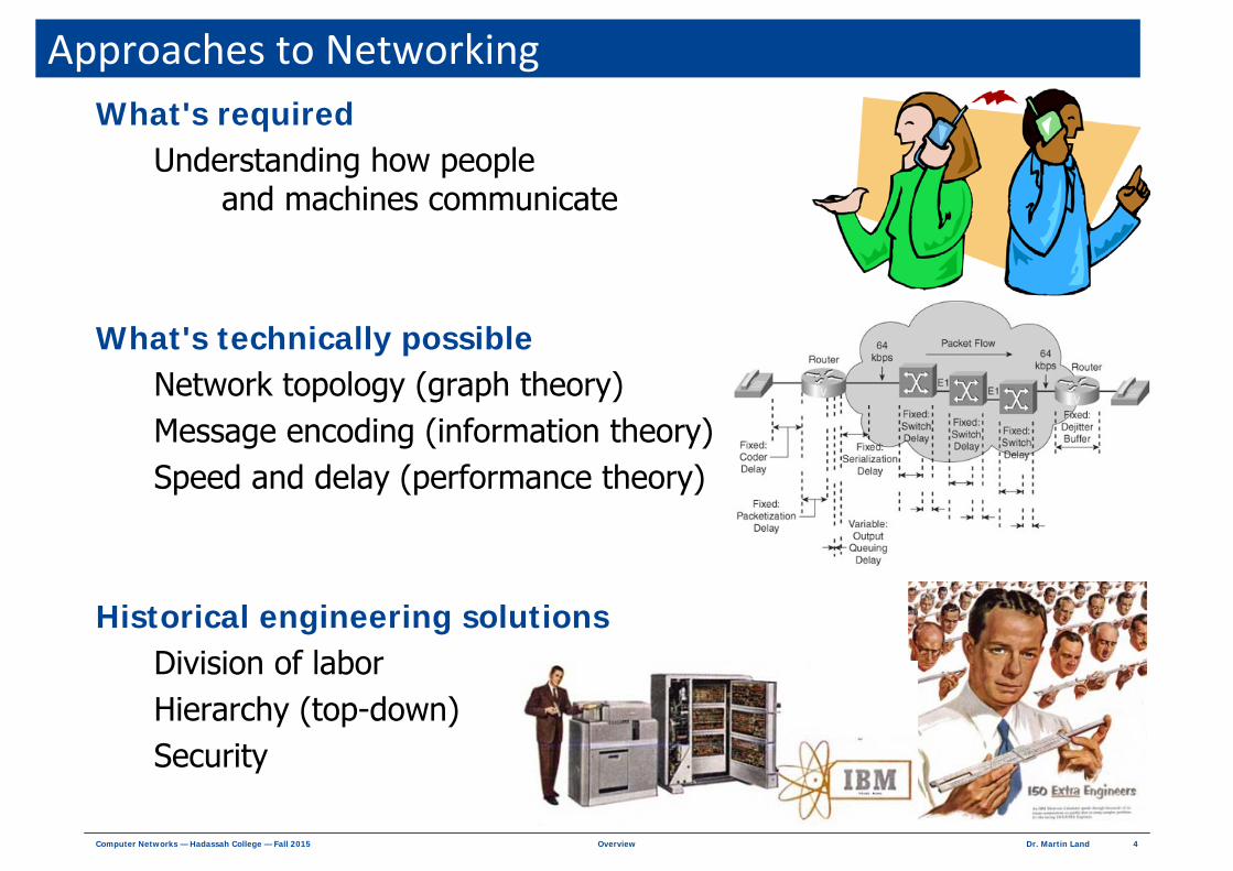
Topology
Node Host node
Network edge — user systemsComputer, workstation, …
Intermediate node Hardware/software systems for data communicationModem, hub, switch, concentrator, multiplexor, router, …
LinkTransmission path between neighboring nodes
HopData transfer between neighboring nodes over one link
ChannelTransmission path between nodesMay include intermediate nodes
Computer network as directed or undirected graph
Link
Channel
HostNode
HostNode
IntermediateNode Host
Node

6Dr. Martin LandOverviewComputer Networks — Hadassah College — Fall 2015
Network Topologies
Bus
Tree
Star
IrregularCompletely Connected
Ring

7Dr. Martin LandOverviewComputer Networks — Hadassah College — Fall 2015
How People (and Machines) CommunicateRequirements
LanguageMediumNames Rules of conversation (protocols)
PreferencesKeep it simpleWork with minimum details necessary for specific taskObtain details dynamically as needed
Models Define roles in computation processDefine roles in communication processDefine rules of behavior for each role

8Dr. Martin LandOverviewComputer Networks — Hadassah College — Fall 2015
Models Typical roles in computation
Application programCalling function / called functionOS serviceClass or object
Typical roles in communication
Example — client/server model
both roles Primary and SecondaryBalanced
swap roles Primary ←→ SecondarySymmetric
responds to requestSecondary
initiates request and accepts responsePrimary
Responds to client request (Secondary)Server
Initiates request to server (Primary)Client
Concurrent application programs / threadsClient and Server

9Dr. Martin LandOverviewComputer Networks — Hadassah College — Fall 2015
Transaction Model
Transaction → request + response
Send Request
Send ResponseReceive Response
Accept RequestRequest
Response
Primary Secondary
Processing
General model with many casesFamiliar examples
main() calls function(x)Procedural transaction
Browser requests page from websiteClient / Server transaction

10Dr. Martin LandOverviewComputer Networks — Hadassah College — Fall 2015
Layered SystemsSystem divided into logical layersWithin layer
Subsystems interact tightlyExample
Between layersSubsystems interact through programming interfaceExample
// subsystems: i, a[i], b[i], c[i]for ( i = 0 ; i < 1024 ; i++){
a[i] = b[i] + c[i] ;}
// subsystems: main(), f(x)main(){
y = f(x) ;}f(x){
return y;}
main()
Calling function, Primary f(x)
Called function, Secondary

11Dr. Martin LandOverviewComputer Networks — Hadassah College — Fall 2015
Standard Agent RelationshipsAgent
Software or hardware entity
Peer relationshipTwo+ independent agents at same layer in layered modelExamples
Independent user application layer programsMicrosoft Word + PowerPointWeb Client (browser) + Web Server (website)
Independent OS layer programsUSB driverWiFi driver
Service relationshipmain() calls function(x)Microsoft Word calls printer driverApplication program opens socket (OS call)

12Dr. Martin LandOverviewComputer Networks — Hadassah College — Fall 2015
Peer‐to‐Peer TransactionPeer-to-Peer (P2P)
Transaction between agents of equal level or statusUsually CLIENT / SERVER model (not necessarily)
ExampleWeb service
Browser and web server — application programs (equal status)
Request Browser (web client) sends page request to web server
Response Web server sends page content to browser
http://www.domain/page.html
page.html
Primary —web client Secondary —web server

13Dr. Martin LandOverviewComputer Networks — Hadassah College — Fall 2015
Protocol ExamplesTransaction protocols
Hypertext Transfer Protocol (HTTP)Browser requests web page from web serverWeb server provides page as response
Post Office Protocol version 3 (POP3)Client system requests email messages from email serverEmail server provides messages as a response
Protocols

14Dr. Martin LandOverviewComputer Networks — Hadassah College — Fall 2015
Service TransactionService
Transaction between agents of unequal level or statusExample
User program makes OS call to open fileUser program is application running above OSOS performs performs low-level services for applications
RequestApplication program issues OS call
ResponseOS opens file and returns file descriptor
Primary — user program
Secondary —OS
open file
filedescriptor

15Dr. Martin LandOverviewComputer Networks — Hadassah College — Fall 2015
Service Transaction ExampleCalling function → Called function
Request Caller invokes called function with parameter
ResponseCalled function returns with result
user(){local workresponse = provider(parameters)local work
}provider(parameters){
local workreturn response
}
Service transactionService request
+Service response

16Dr. Martin LandOverviewComputer Networks — Hadassah College — Fall 2015
General Layered Service ModelTask divided into layers
Layer n
Provider to layer n + 1User to layer n – 1
Interface
Boundary between layers
Simple example
Two service transactionsLayer 3 calls layer 2Layer 2 calls layer 1
Layer 2 Provider to layer 3User to layer 1
layer_3(){local workresponse-2 = layer_2(p3-2)local work
}layer_2(p3-2){
local workresponse-1 = layer_1(p2-1)local workreturn response-2
}layer_1(p2-1){
local workreturn response-1
}

17Dr. Martin LandOverviewComputer Networks — Hadassah College — Fall 2015
ProtocolProtocol
Rules for transaction between peersExamples
SyntaxSemanticsSynchronizationProceduresAlgorithms Naming
Layered communicationCommunication task divided into layers
Protocol stackSpecific peer-to-peer protocol defined at each layer
Protocols

18Dr. Martin LandOverviewComputer Networks — Hadassah College — Fall 2015
Protocol Stack
Tanenbaum (3rd ed) Figure 1‐9, p. 17

19Dr. Martin LandOverviewComputer Networks — Hadassah College — Fall 2015
Services and Protocols

20Dr. Martin LandOverviewComputer Networks — Hadassah College — Fall 2015
Protocol Stack Example
Tanenbaum (3rd ed) Figure 1‐10, p. 19
21Dr. Martin LandOverviewComputer Networks — Hadassah College — Fall 2015
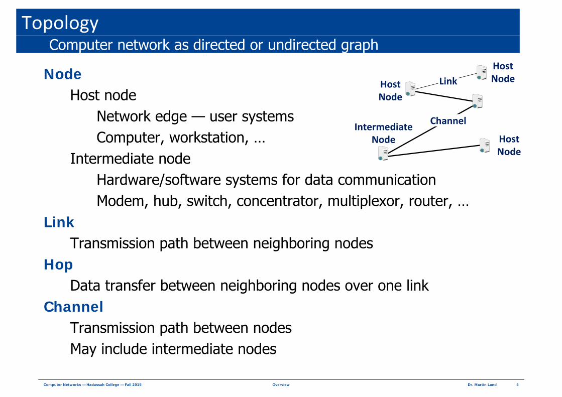
Layered Protocol ModelLayer n protocol
Performs VIRTUAL COMMUNICATION between layer n peers Exchanges layer n information with layer n peer
Layer n serviceReceives request from layer n + 1Passes request to layer n – 1 for communication serviceReceives response from layer n – 1
Layer 1
…
Layer n – 2
Layer n – 1
Layer n
Layer 1
…
Layer n – 2
Layer n – 1
Layer nLayer n protocol
Virtual peer transaction
Layer 1 protocol
Physical peer transaction
ServiceTransactions Layer n – 2 protocol
Virtual peer transaction

22Dr. Martin LandOverviewComputer Networks — Hadassah College — Fall 2015
Encapsulation — Protocol HeadersLayer n – 1 protocol
Receives service request from layer nRequest = message to layer n peer agent
Adds layer n – 1 HEADER
Header = message to layer n – 1 peer agent
Protocol Data Unit (PDU) at layer n – 1 Message output from layer n – 1 protocolLayer n PDU + layer n – 1 header
Service Data Unit (SDU) at layer n – 1 Layer n PDU = random data for layer n – 1
Layer n – 1
Layer n
Layer n – 1
Layer n
Layer n – 1 SDU = Layer n PDULayer n –1 Header
Layer n PDU
Layer n – 1 PDU

23Dr. Martin LandOverviewComputer Networks — Hadassah College — Fall 2015
Functional Analysis of CommunicationOpen System Interconnection Model (OSI)
DescriptionFunctionLayer
Physical
Data Link
Network
Transport
Session
Presentation
Application
Data transmission between neighboring hardware agents on physical channels (electrical, optical, radio, …)1
Control of data transmission between neighboring hardware agents (one hop)2
End-to-end data routing between host nodes via multiple hops3
Reliable end-to-end data exchange between host nodesPrevents data loss, errors, repetitions, ordering errors
4
Identification, separation, and continuity of multiple ongoing data transactions between software agents5
Syntax and semantics of exchanged data6
Exchange of data between user applications7

24Dr. Martin LandOverviewComputer Networks — Hadassah College — Fall 2015
Example of OSI Functional LayersHypothetical OSI web browser
Example FunctionsLayer
Physical
Data Link
Network
Transport
Session
Presentation
Application
Data bits exchanged with next-hop data communication hardware on physical channels
Data bytes exchanged between host computer and next-hop data communication hardware
Find route to web server by network addressFile requests/data exchanged with server by network address
Each request/response checked for errors and completenessEach requested file provided to session layer without errors
Web page includes multiple graphic filesEach file requested and received as separate conversation
Encoding standard for Hebrew (Windows, UTF, ISO, …)
Browser provides GUI — requests web pages by URL
25Dr. Martin LandOverviewComputer Networks — Hadassah College — Fall 2015
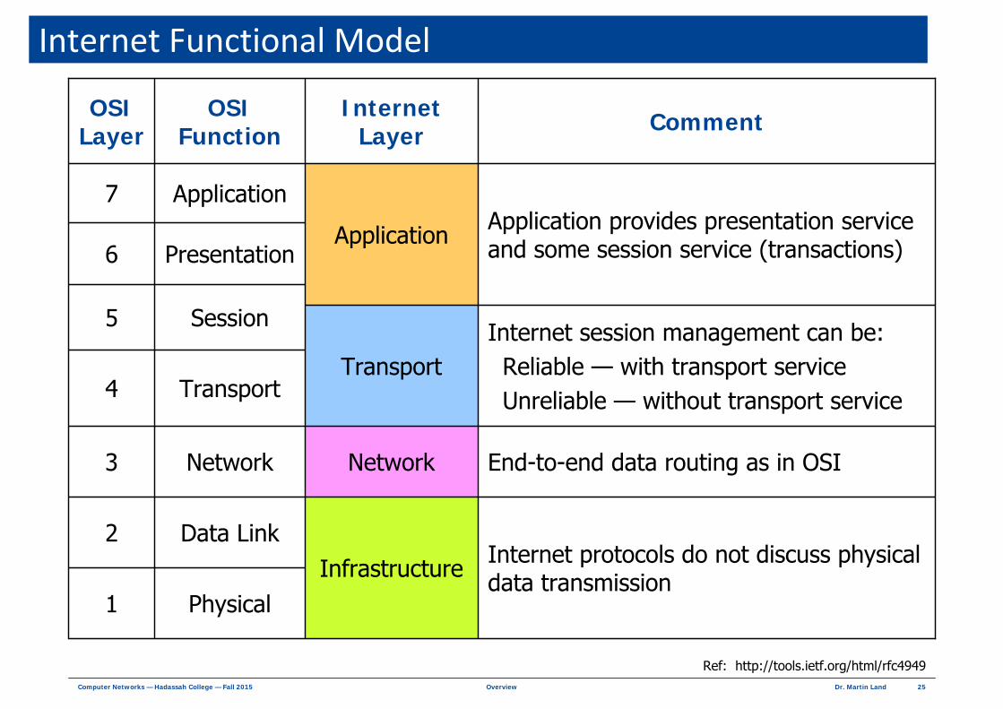
Internet Functional Model
Physical
Data Link
Network
Transport
Session
Presentation
Application
OSI Function CommentInternet
LayerOSI
Layer
Infrastructure
Network
Transport
Application
1
Internet protocols do not discuss physical data transmission
2
End-to-end data routing as in OSI3
4
Internet session management can be:Reliable — with transport serviceUnreliable — without transport service
5
6Application provides presentation service and some session service (transactions)
7
Ref: http://tools.ietf.org/html/rfc4949

26Dr. Martin LandOverviewComputer Networks — Hadassah College — Fall 2015
Example of Internet Functional LayersTypical web browser
Example FunctionsLayer
Infrastructure
Network
Transport
Application
Network layer messages sent to Internet data communication equipment
File requests/data exchanged with server by network routing (RIP, OSPF, IGRP, BGP)Transfer data across network by network address (IP)
Each file request conversation identified for error control (TCP)Each requested file provided to session layer without errors
Browser provides GUI — requests web pages by URLTranslate (DNS) URL into network address (IP) for web server
Encoding standard for Hebrew (Windows, UTF, ISO, …)Web page includes graphic files
Each file requested/received as separate conversation (HTTP)

27Dr. Martin LandOverviewComputer Networks — Hadassah College — Fall 2015
Internet PDUsProtocol Data Unit (PDU)
PDUMessageLayer
Signal
Frame
Datagram
Segment
Message
Bits
Header + Trailer
Header
Header
Data
Physical
Data Link
Network
Transport
Application
T-DLApplication DataH-TH-NH-DL
Headers added by layers 2, 3, 4 Trailer
Host-to-host data frame
network datagram
transport segment

28Dr. Martin LandOverviewComputer Networks — Hadassah College — Fall 2015
Internet EndpointsNetwork Endpoint
Address of SOFTWARE AGENT running in HARDWARE AGENT
Network Address + Port
Physical connection
Identifies hardware device (node) in local network
Identifies computing node in global network
Software address identifies program exchanging data
Associates file descriptor with network endpoint
Communication IDLayerSystem Level
Physical
Data Link
Network
Transport
Application
Attachment
Hardware Address
Network (IP) Address
Port
Socket
Hardware
OperatingSystem
User
Well-known portsStandard services defined on ports 0 – 1023

29Dr. Martin LandOverviewComputer Networks — Hadassah College — Fall 2015
Data Communication Equipment (DCE)
Physical
Data Link
Network
Layer
Modulator/demodulator (modem)Transmits and receives digital bits over physical medium
Manages physical transmission layerExchanges Frames among neighboring hardware agents
Receives Network Datagrams in Data Link FramesSends Datagrams in Data Link Frames to next hop on path to destination
Function DCE
Network Interface
Card
Switch(Hub)
Router
Ethernet Hub
WiFi Hub
Internet Router
Internet Core
30Dr. Martin LandOverviewComputer Networks — Hadassah College — Fall 2015
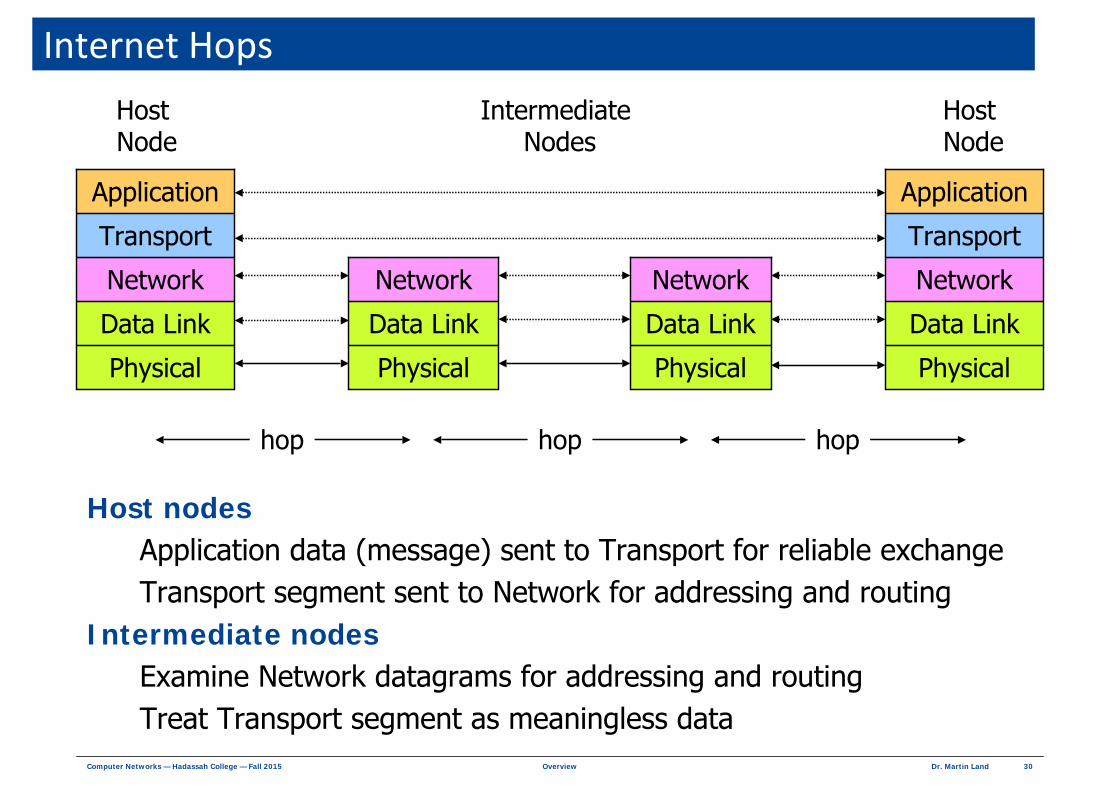
Internet Hops
Host nodesApplication data (message) sent to Transport for reliable exchangeTransport segment sent to Network for addressing and routing
Intermediate nodesExamine Network datagrams for addressing and routingTreat Transport segment as meaningless data
Physical
Data Link
Network
Transport
Application
Physical
Data Link
Network
Transport
Application
Physical
Data Link
Network
Physical
Data Link
Network
Host Node
Host Node
Intermediate Nodes
hop hop hop

31Dr. Martin LandOverviewComputer Networks — Hadassah College — Fall 2015
Network Zoo
Wide Area Networks (WAN)Public Switched Telephone Network (PSTN)
Local loop, backbone, PDH/SDH, ESS, ISDNPublic Switched Data Network (PSDN) — X.25
Broadband Integrated NetworkATM, B-ISDN, Frame Relay
Cellular 2.5G (GPRS/EDGE), 3G (UMTS, CDMA2000), 4G (WCDMA)
Local Area Networks (LAN < 2 km)Ethernet, WiFi, VLAN, token ring, token bus, FDDI, …
Personal Area Network (PAN < 20 m)Bluetooth, ZigBee, IrDA, …
Commercial network protocol stacksSNA, DECnet, Windows Networking, AppleNet, Netware, …
Many network types with specific protocol stacks
32Dr. Martin LandOverviewComputer Networks — Hadassah College — Fall 2015
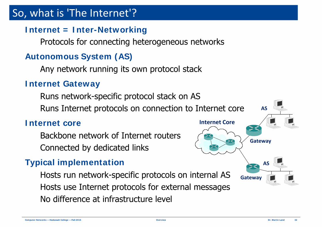
So, what is 'The Internet'?Internet = Inter-Networking
Protocols for connecting heterogeneous networks
Autonomous System (AS)Any network running its own protocol stack
Internet Gateway Runs network-specific protocol stack on ASRuns Internet protocols on connection to Internet core
Internet coreBackbone network of Internet routersConnected by dedicated links
Typical implementationHosts run network-specific protocols on internal ASHosts use Internet protocols for external messagesNo difference at infrastructure level
Gateway
Gateway
Internet Core
AS
AS

33Dr. Martin LandOverviewComputer Networks — Hadassah College — Fall 2015
Intranet?Intranet
Using internet protocols in ASPure intranet
Internet protocols above Ethernet/WiFi LANWindows network
Uses Internet protocols for transport and addressingUses Microsoft protocols for message syntax, node location, …
Gateway
Gateway
Internet Core
Intranet AS
AS
Internet protocolsover Ethernet

34Dr. Martin LandOverviewComputer Networks — Hadassah College — Fall 2015
Hey! Hey! You! You! Get Off of My Cloud
Cloud ≠ Internet ≠ NetworkNetwork
Collection of agents with single defined protocol stack
Internet Collection of agents using inter-networking protocols at layers 3 & 4
Cloud Business modelOrganization A rents computing service from provider COrganization A offers service to user B via provider C network
words and music: Mick Jagger and Keith Richards
ProviderC
Massive Computing
Infrastructure
OrganizationA
No Computing Infrastructure
UserB
Client Computing
Infrastructure
BusinessContract
ServiceOffer
ServiceUse
ServiceConfiguration

35Dr. Martin LandOverviewComputer Networks — Hadassah College — Fall 2015
Why Cloud Computing?Outsourcing service model
User gets computing services from service providerService Level Agreement (SLA) guarantees customer serviceProvider handles operations+administration+maintenance (OAM)
Business advantages to organization Economies of scale — large provider can do it cheaperCuts labor/capital costs from balance sheet → happy investors
Based on standard technologiesCloud service organized from conventional resources
Hardware + software + networkProvider offers menu of services
Not a fundamentally different computing technologyUnique technological issues
Service reliability — provider committed to SLAOptimization of provider-side resource configurationOptimization of user-side resource configuration

36Dr. Martin LandOverviewComputer Networks — Hadassah College — Fall 2015
Service Configuration in Cloud ComputingInfrastructure as a service (IaaS)
Organization sees virtual hardware environment Real hardware or hypervisor / system virtual machine
Organization installs OS → installs software → user runs jobs
Platform as a service (PaaS)Organization sees virtual OS environment
OS on single hardware platform or virtual OS
Organization installs software → user runs jobs
Software as a service (SaaS)Organization sees virtual application software environment
Applications running on private OS or "sandboxed" on shared OSSandbox — private execution environment per application instance
User runs jobsStorage as a service (STaaS)
User sees virtual mounted storage device

37Dr. Martin LandOverviewComputer Networks — Hadassah College — Fall 2015
Centralize → Decentralize → Centralize → ?1950s — 60s
Centralized mainframe computer + multiple OS instances over hypervisorTimesharing OS serves multiple usersUser sees OS environment via dumb terminal (thin client)
1970s User applications offloaded to minicomputers + timesharing servicesUser sees timeshared OS environment via dumb terminal
1980sUser applications offloaded to personal workstations (PC)User sees single-user OS environment running locally
1990sNetwork single user workstations User sees single-user OS environment running locally
2000sCentralized control of local OS environment by IT departments
2010sCloud + netbook / tablet / smart phone — dumb terminal with high-res GUI

38Dr. Martin LandOverviewComputer Networks — Hadassah College — Fall 2015
Issues in Cloud ComputingCost
Provider issuesEconomies of scale ⇒ lower cost per compute job
Organization issuesCapital + OAM costs → operating costsLower start-up costs ⇒ operating debt
Reliability Provider issues
Redundant infrastructure → continuity + disaster recoveryCentralized management of OAM, security, performanceVirtualization → serve multiple users on physical serverMultitenancy → provide multiple sandboxed application instances on OS
User sees guaranteed serviceAgility
Organization / provider reconfigure service as needed Growth, load balancing, time-zone serving

39Dr. Martin LandOverviewComputer Networks — Hadassah College — Fall 2015
Cloud OwnershipPublic cloud
Service provider as public utility — sells / rents computing serviceInitial providers leverage large existing infrastructureAmazon, Microsoft, Google, IBM
Menu of services at fixed prices
Private cloudCloud infrastructure for private organizationManaged internally or outsourcedIsolates service developers from implementation issues
Standard development platform
Requirements for economic justificationLarge organization Technology-based servicesFrequent new serviceExample — internet content provider

40Dr. Martin LandOverviewComputer Networks — Hadassah College — Fall 2015
Programming in the CloudDepends on environment
IaaS — Organization sees virtual hardware environmentPaaS — Organization sees virtual OS environmentSaaS — Organization sees virtual application software environment
IBM BluemixSaaS from IBMFree accounts for students using [email protected] addressBluemix DevOps Services
Develop, track, plan, and deploy software on IBM cloud serviceCollaboration tools — Git, Jazz SCM, GitHubBuild application → deploy to IBM cloud Supports
Arduino, C, C#, C++, CSHTML, Embedded, JavaScript (ejs) Erlang, Go, HTML, abstraction markup language (Haml) Jade, Java, JSON, Lua Objective‐C PHP, Python, Ruby, Swift, Virtual, Basic (vb) VMHTML, XHTML, XML, Xquery, yaml, Launch, file Dockerfile, gitignore, git config, cfignore
"You can go from source code to a running app in minutes."

41Dr. Martin LandOverviewComputer Networks — Hadassah College — Fall 2015
Some Internet ProtocolsApplication layer transactions
Hypertext Transfer Protocol (HTTP)
Transport layer Transport Control Protocol (TCP)
Reliable transport service
User Datagram Protocol (UDP)Unreliable transport service
Network layerInternet Protocol (IP)
Node addressing
Internet Control Message Protocol (ICMP)Messages about messaging
Routing protocols (RIP, OSPF, IGRP, BGP)Learn network topology for message forwarding
792ICMP
791IP
768UDP
793TCP
2616HTTP
RFCProtocol
RFC — Internet standard

42Dr. Martin LandOverviewComputer Networks — Hadassah College — Fall 2015
What Internet Protocols Do
Hypertext Transfer Protocol (HTTP)Application layer transactions
Some examples
Responses
Requests
Status of transactionStatus
Contents of requested fileData
Delete file by nameDelete
Replace file by namePost
Retrieve file by nameGet

43Dr. Martin LandOverviewComputer Networks — Hadassah College — Fall 2015
What Internet Protocols Do
Domain Name Service (DNS)Translates node name to Internet address (and vice versa)
Example
Some examples
c:\> nslookup www.hadassah.ac.ilName: www.hadassah.ac.ilAddress: 212.179.79.228

44Dr. Martin LandOverviewComputer Networks — Hadassah College — Fall 2015
What Internet Protocols Do
Transport Control Protocol (TCP)Reliable transport service
SenderLabel source and destination software by port numberNumber outgoing segmentsWait for ACK (acknowledgment) for outgoing segmentsRetransmit segments if no ACK before timeout Negotiate segment size (for error and congestion control)
ReceiverCheck completeness and order of incoming segments Check incoming segments for errorsSend ACK for good segmentsProvide good incoming segment to destination software
Some examples

45Dr. Martin LandOverviewComputer Networks — Hadassah College — Fall 2015
What Internet Protocols Do
Internet Protocol (IP)Best effort network serviceNo guarantee of delivery
IP version 4 addressFour octets 0.0.0.0 to 255.255.255.255 (many reserved addresses)
SenderAttach source and destination network addresses to segmentRoute IP datagram to next hop along route
Receiver Intermediate node — route IP datagram to next hop along routeHost node — provide segment to transport layer
Some examples

46Dr. Martin LandOverviewComputer Networks — Hadassah College — Fall 2015
Network Infrastructure
ScaleWide Area Network (WAN < earth)Local Area Network (LAN < 2 km)Personal Area Network (PAN < 30 m)
Medium
Traffic statisticsConstant Bit Rate (CBR) — peak data rate = average data rateVariable Bit Rate (VBR) — peak data rate > average data rate
Layers 1 + 2 — bits, bytes, signals, cables, electronics
Copper wire and cableElectrical signals
Requires legal right to transmit radioOpen space
Radio wave signals
Requires legal right to install cablesOptical fiber
Light wave signals

47Dr. Martin LandOverviewComputer Networks — Hadassah College — Fall 2015
Connectivity = Medium + Topology Point-to-point
Dedicated link from node to nodeFastest and most complex
SwitchDedicated link from node to switchSwitch connects nodes on request
Non-blocking provides n × (n – 1) connectivityBlocking provides n × m connectivity (m < n – 1)
Shared mediumNodes share medium accessContention
Nodes compete for access
PollingCentral controller polls nodes
bus
wireless

48Dr. Martin LandOverviewComputer Networks — Hadassah College — Fall 2015
Physical Transmission Serial data rate at physical layer
Bits per second = bps = b/sBytes per second = B/s1 B/s = 8 b/s
Capacity (bandwidth)Maximum data rate on mediumFixed by transmitter / medium / receiverLimits
Speed of circuitsSignal to noise ratio (SNR)
01

49Dr. Martin LandOverviewComputer Networks — Hadassah College — Fall 2015
Physical Transmission Throughput
Takes account ofUtilization = % time transmitter sendingErrors ⇒ re-transmission ⇒ more data on same capacityDelays ⇒ less data received on same capacity
2 3 1 4
utilization = 10 / 16 = 62.5%
0 16
bit errors
bits received
error-free data received per secondthroughput
capacity=

50Dr. Martin LandOverviewComputer Networks — Hadassah College — Fall 2015
Baud Rate
SymbolPhysical signal that encodes bits
Symbol rate (Baud rate)Symbols transmitted per second
Bit transmission rateBits transmitted per second = (symbols / second) × (bits / symbol)
ExamplePulse amplitude modulation (PAM)Define 2N electrical levels from 0 to 11…1Each symbol (level) transmits N data bits
0001
1011
N = 2 (4 Level) PAM1.00 V
0.50 V
0.75 V
0.25 V
Symbols per second

51Dr. Martin LandOverviewComputer Networks — Hadassah College — Fall 2015
Baud Rate
33 kbps dial-up modemDefine 210 = 1024 electrical symbols (max for SNR on phone line)Baud rate = 3300 symbols / second
Bits transmitted per secondData rate = (3300 symbols / second) × (10 bits / symbol)
= 33,000 bps
0000000000
00000000010000000010
1111111111
N = 10 (1024 Level) PAM
...
Symbols per second

52Dr. Martin LandOverviewComputer Networks — Hadassah College — Fall 2015
Data Concentration High capacity link
No single node can utilize link capacityExample
Optical fiber cable with 4 fibers at 25 Gbps = 100 Gbps
Multiplexing Combine multiple nodes onto one linkExample
Optical fiber with 25 Gbps data rateCombine 25 nodes transmitting at 1 Gbps
25 inputsat 1 Gb/s
1 output at25 Gb/s
Multiplexor

53Dr. Martin LandOverviewComputer Networks — Hadassah College — Fall 2015
Multiplexing MethodsFrequency Division Multiplexing (FDM)
Divide available frequencies (bandwidth) among nodesNodes transmit simultaneously on different frequencies
ExampleFM radio uses 88 MHz to 108 MHz = 20 MHz bandwidthDivide 20 MHz into 100 channels = 200 kHz per FM channel
88 91.3 93.9 95.5 96.6 97.8 101 104.8 MHz
88 מ וס י קה צ"ג ל ' ב צ"ג ל ' ג י ר ושל ים ' ד

54Dr. Martin LandOverviewComputer Networks — Hadassah College — Fall 2015
Multiplexing MethodsTime Division Multiplexing (TDM)
Divide capacity into time slotsNode transmits in assigned time slot
ExampleE1 digital line transmits at 2048 kbpsDivide 2048 kbps line into 32 time slots = 64 kbps per node
32 x 64 kbps = 2048 kbps = 2.048 Mbps
32 inputsat 64 kbps
1 output at2.048 Mbps
Multiplexor
32 outputsat 64 kbps
1 input at2.048 Mbps
Demultiplexor

55Dr. Martin LandOverviewComputer Networks — Hadassah College — Fall 2015
E1 Multiplex
1125 s/sample
8000 samples/second= μ
32 inputsat
8000samples/sec
1 output at32 x 8000 x 8 bps = 2.048 Mbps
byte from line 0
byte from line 1
byte from line 2
byte from line 31
0 1 2 ... 31
125 sμ
Every 125 sec multiplexor (MUX)
receives 8‐bit sample from each line
(isochronous)
μ
125 sec/frame3.91 sec/sample
32 samples/frameμ
= μ

56Dr. Martin LandOverviewComputer Networks — Hadassah College — Fall 2015
GSM CellularMixed Multiplexing
Time Division Multiple Access (TDMA)Used on GSM / UMTS phones — 2G and 3GCombines FDM and TDM
Frequency Division Multiplexing (FDM)GSM bands = 25 MHzDivide 25 MHz into 125 channels = 200 kHz per channelTransmit 270 kbps over 200 kHz channel
Time Division Multiplexing (TDM)Divide 270 kbps into 8 times slots = 33 kbps per user33 kbps = 23 kbps for voice + 10 kbps control

57Dr. Martin LandOverviewComputer Networks — Hadassah College — Fall 2015
Data Statistics — CBRConstant Bit Rate (CBR)
Isochronous data Equal time interval between bitsBits per second = constant
Average data rateAverage data rate = peak data rate = minimum data rate
ExampleUncompressed digital audioSample analog signal every T seconds
Round-off sample to N-bit number from 0 to 2N – 1
Digital audio stream at N / T bps

58Dr. Martin LandOverviewComputer Networks — Hadassah College — Fall 2015
Digital Voice on Telco Telephone Sample analog voice signal every 0.125 ms
0.125 ms per voice sample ⇒ 8000 voice samples / second
Round-off sample to 8-bit data
Data ∈ {0, 1, 2, ... , 255}Sample = {158.276, 158.879, 159.724, 159.821, 159.312, 158.791}Data = {158, 159, 160, 160, 159, 159}
DS-0 stream(8000 samples / second) × (8 bits / sample) = 64 kbps64 kbps digitized voice (no compression)
158159
160 160159 159
157
158
159
160
161
t
59Dr. Martin LandOverviewComputer Networks — Hadassah College — Fall 2015
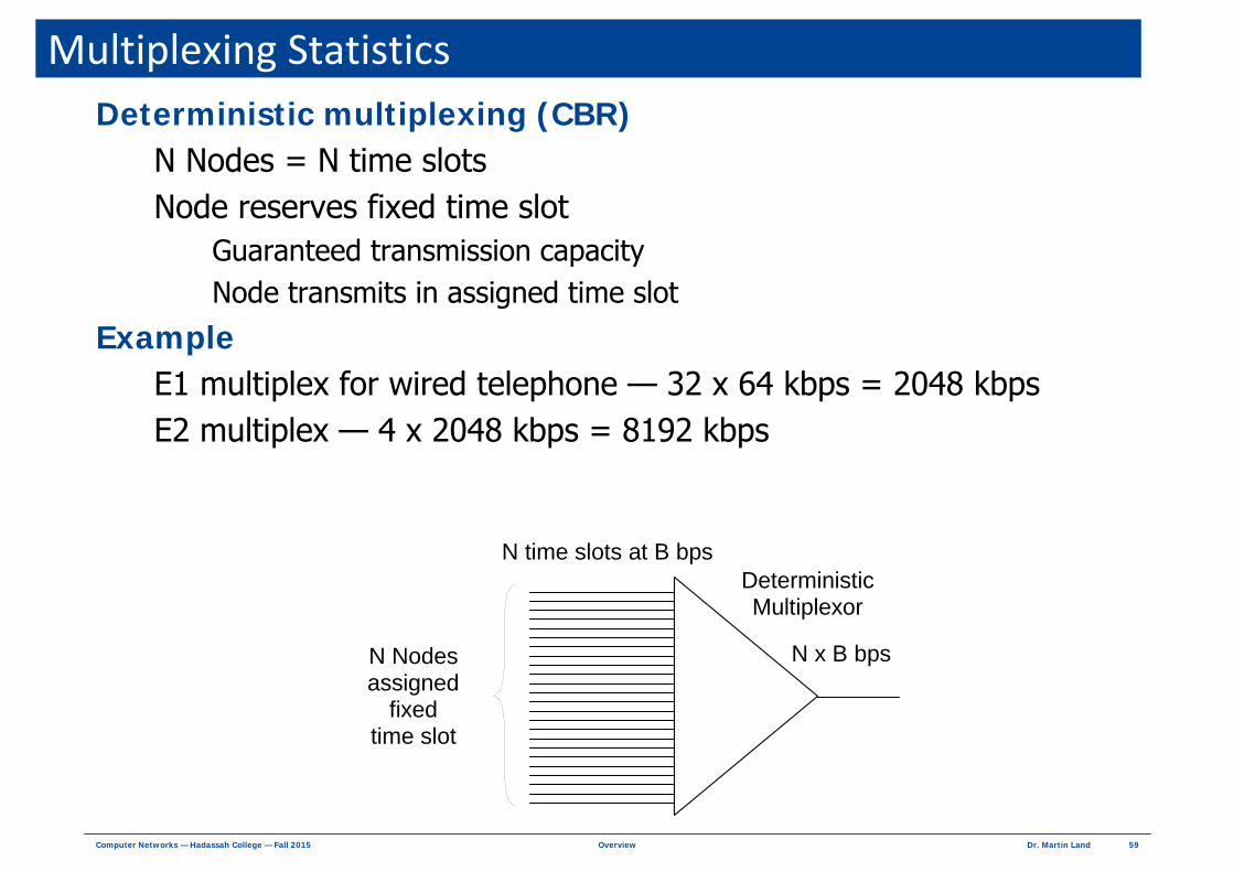
Multiplexing StatisticsDeterministic multiplexing (CBR)
N Nodes = N time slotsNode reserves fixed time slot
Guaranteed transmission capacityNode transmits in assigned time slot
Example E1 multiplex for wired telephone — 32 x 64 kbps = 2048 kbpsE2 multiplex — 4 x 2048 kbps = 8192 kbps
N Nodesassigned
fixedtime slot
DeterministicMultiplexor
N time slots at B bps
N x B bps

60Dr. Martin LandOverviewComputer Networks — Hadassah College — Fall 2015
Data Statistics — VBR Variable Bit Rate (VBR)
Bursty dataPeak data rate B > average data rate λAssume packets are independent (Poisson statistics)
ExampleData sent by time-of-day client
Request time-of-day (1000 bits) once every hour (3600 seconds)Average data rate = 1000 bits / 3600 seconds = 0.28 bps
Peak data rate = 55 Mbps on 802.11g WiFiPeak data rate 55 Mbps > average data rate = 0.28 bps
( )
( ) ( )
, ,
, ,!
kT
P k T kT
TP k T e
kλ
λ
λ
λλ −
=
=
probability of bits arriving
in seconds when average rate =

61Dr. Martin LandOverviewComputer Networks — Hadassah College — Fall 2015
Multiplexing StatisticsStatistical multiplexing (VBR)
M nodes > N time slotsBursty data
Average data rate λ < peak data rate B
Average traffic rate = M x λ < capacity rate = N x BActual traffic < capacity ⇒ OK
Actual traffic > capacity ⇒ data delayed or lost
Example Internet routers
M Nodesrequest
time slots
StatisticalMultiplexor
M > N time slots at B bps
N x B bps

62Dr. Martin LandOverviewComputer Networks — Hadassah College — Fall 2015
Overflow in VBROverflow
Actual traffic > capacity Short time (a few time slots) ⇒ data delayed
Long time (many time slots) ⇒ buffer overflow ⇒ data lost
Overflow probabilityAverage traffic rate = M x λ
Average data arriving in time T = M x λ x T
Capacity rate = N x BData capacity in time T = N x B x T
Overflow in time TActual data arriving in time T > N x B x T
N x B x T + 1 or N x B x T +2 or N x B x T +3 or ...Independent outcomes
( ) ( ) ( ) ( )
1
1 2 ...!
overflow∞
− λ
= +
λ= + + = ∑
k
k
P P or or ek
M T
NBT
M TNBT NBT

63Dr. Martin LandOverviewComputer Networks — Hadassah College — Fall 2015
Overflow ExampleAverage traffic on network
λ = 10 packets / second per nodeM = 10 nodes
Average packets in 0.1 second = M x λ x T= 10 nodes x (10 packets / second per node) x 0.1 second
= 10 packets
Maximum traffic on network (capacity)B = 25 packets / second per node
N = 4 nodes
Maximum packets in 0.1 second = N x B x T
= 4 nodes x (30 packets / second per node) x 0.1 second
= 12 packets
Overflow condition for T = 0.1 secondOverflow if actual traffic > N x B x T
( ) ( ) ( )
!10
13
10overflow 0.21 21%
∞−
=
= = =∑k
k
P ek

64Dr. Martin LandOverviewComputer Networks — Hadassah College — Fall 2015
SwitchingSwitch
Multiplexor + DemultiplexorData at input_porti → output portji,j = 0, 1, 2, ... , N - 1
Example
N inputs x B bps= N x B bps
N outputs x B bps= N x B bps
Capacity = C bps
switch
1
2
3
4 1
2
3
4

65Dr. Martin LandOverviewComputer Networks — Hadassah College — Fall 2015
Circuit SwitchingDeterministic multiplexing
Capacity C = N × BDedicated (reserved) link
input_porti → output portjNo competitionGuaranteed capacity B — if used or not
ExampleBezeq phone call64 kbps from telephone to telephone (even if no one speaks)
N inputs x B bps= N x B bps
N outputs x B bps= N x B bps
Capacity = C bps
switch

66Dr. Martin LandOverviewComputer Networks — Hadassah College — Fall 2015
Packet SwitchingStatistical multiplexing
Capacity C = M × B < N × BDynamical time slot assignment (on request)
input_porti → output portjCompetition
More ports than capacity
Demand > capacity ⇒ delay
ExampleInternet routerPacket queue — first come first served
N inputs x B bps= N x B bps
N outputs x B bps= N x B bps
Capacity = C bps
switch

67Dr. Martin LandOverviewComputer Networks — Hadassah College — Fall 2015
Connection TypesConnection
State machine associated with data exchange
Connection-orientedFirst set-up data channelMultiple data transactions associated with connection stateMonitor channel state during data exchangeClose channel after data exchangeExample — phone call
Enter number → answer call → extended conversation → disconnect
ConnectionlessTransmit data with no prior channel set-upNo channel state defined by nodesEach message independentExample — email message
Send email → hope message arrives → hope message is found / read

68Dr. Martin LandOverviewComputer Networks — Hadassah College — Fall 2015
Datagram Service Network of routers and links
Packet switchingConnectionless
Each datagramHas source and destination address in header
Data Link header or Network header
Routed individually through networkDatagrams may follow separate routesExample
B → 1 → 4 → 6 → FB → 1 → 5 → 6 → F
AB
C
E
F
D
1
2 3
4
5
6
datasrc = B dest = F

69Dr. Martin LandOverviewComputer Networks — Hadassah College — Fall 2015
Switched Virtual Circuit (SVC) Network of switches and links
Circuit switching or packet switchingConnection-oriented
Switched Virtual Circuit (SVC) Set-up / close messages carry source and destination addresses
Example
Packet routing by VC ID in header (layer 2 or layer 3)Every packet follows same VC route Example
AB
C
E
F
D
1
2 3
4
5
6
Set-up VC – 1: B → 1 → 4 → 6 → F
dataVC – 1
70Dr. Martin LandOverviewComputer Networks — Hadassah College — Fall 2015
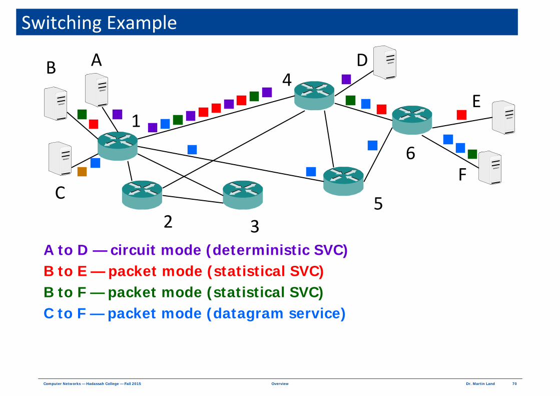
A to D — circuit mode (deterministic SVC)B to E — packet mode (statistical SVC)B to F — packet mode (statistical SVC)C to F — packet mode (datagram service)
Switching Example
AB
C
E
F
D
1
2 3
4
5
6

71Dr. Martin LandOverviewComputer Networks — Hadassah College — Fall 2015
Transmission Delay
Transmission delay TT
TT = Time to inject bits into line = (bits in packet) / (bits per second)
Processing delay Tproc
Packet process time in intermediate nodeSVC with fixed route ⇒ shorter delay than datagram routing
Propagation delay Tprop
Tprop = (length of cable) / (signal speed)
Queuing delay TQ
Time packet waits in buffer for previous packets (congestion)TQ = (service time per packet) × (packets waiting in buffer)
Example: 1000 Mb / 100 Mbps = 10 sec
Example: 4 km / (2 × 10⁸ km/s) = 2 × 10⁻⁸ sec << 10 sec
TT TpropTQ NodeTprocNode

72Dr. Martin LandOverviewComputer Networks — Hadassah College — Fall 2015
Example of Queuing Delay
Queuing delay TQ
TQ = (service time per packet) × (packets waiting in buffer) Packets waiting in buffer = 1 / (1 – utilization)
Queuing delay exampleService time per packet = 10 ms / packet
Service rate = 1 / (10 ms / packet) = 100 packets / secondAverage traffic = S = 85 packets / second
Utilization = (85 packets / second) / (100 packets / second) = 0.85Buffer level = 1 / (1 – 0.85) = 6.67
TQ = (10 ms / packet) × 6.67 packets = 67 msC = switch capacity = service rate = 100 packets / second
Demand > 100 buffer ⇒ overflow ⇒ excess delay
( ) ( ) 85
1 1 101
85 0.05! !
demand demand k k
S
k C k C k
SP C P k e ek k
∞ ∞ ∞− −
= + = + =
> = = = = =∑ ∑ ∑
TT TpropTQ NodeTprocNode

73Dr. Martin LandOverviewComputer Networks — Hadassah College — Fall 2015
Error ControlBit error
Data 1 received as 0 or data 0 received as 1
Packet LossCongestion or buffer overflow → packet discarded
Error detectionError correction code / redundancy code / checksumChecksum transmitted with data in header / trailerReceiver compares independent hash with transmitted code
Error controlRequired
Discard corrupt packet
Optional Retransmit discarded / missing packets
bit errors in received dataBit Error Rate (BER)
bits in received data=
packets lostPacket loss rate
packets transmitted=

74Dr. Martin LandOverviewComputer Networks — Hadassah College — Fall 2015
Network ScalePrivate network
Small Office / Home Office (SOHO) Small number of computers in a few roomsSimple Ethernet / WiFi LAN
EnterpriseMany nodes in large building / campusComplex Intranet
Access networkProvide user connection to Internet coreInfrastructure provider manages layers 1 and 2Internet Service Provider (ISP) manages layers 3 and 4
Internet coreNetwork of routers and links at layer 3Infrastructure provider manages links at layers 1 and 2Links are typically built over complex network systems

75Dr. Martin LandOverviewComputer Networks — Hadassah College — Fall 2015
Private Networks Simple Ethernet / WiFi LAN
Ethernet switching hub4 to 16 nodesFull connectivity (non-blocking)10 / 100/ 1000 Mbps
WiFi hubMore nodes lowers performanceNodes compete to transmit to hub11 / 54 / 100+ Mbps
Complex IntranetMultiple LAN hubsHubs connected
Directly (bridging)Indirectly (routing)
76Dr. Martin LandOverviewComputer Networks — Hadassah College — Fall 2015
Non‐Private Networks
Service infrastructure Routing + accounting nodes in office buildings
Link infrastructure Cables + radio channels on public / private property
Legal and licensing issues
Controlled by companies in cable businessesTelephone companies (Telco)Cable TV companies Electric companies Railroads companies
Choices for small business Intranet at 3 locationsPay service provider monthly Or
Purchase LAN hubs and routersLease cables from Telco
Access + core

77Dr. Martin LandOverviewComputer Networks — Hadassah College — Fall 2015
Telephone Network
Local loopWired connection to most buildingsCan carry 1 Mbps (up to 4 km) to 25 Mbps (up to 300 m)Voice network
Analog voice channel from 300 to 3300 HzDigitized voice at 64 kbps
Local presence (central office) in every neighborhoodLocal loop attached to non-blocking switches
Tree network of switchesCentral offices connect to regional offices on fiber optic backbone
Global broadband switched virtual circuit (SVC) networkCircuit mode switches (ESS7) for 64 kbps voiceCircuit / Packet mode layer 2 switches (ATM) up to 2.5 GbpsPrivate routers throughout network for Internet traffic
It's everywhere

78Dr. Martin LandOverviewComputer Networks — Hadassah College — Fall 2015
Telephone Network
local loop
fiber optic cables
fiber optic cablesup to 40 Gbps
ESS ATM
Central Office
Router
local loop
ESS ATM
Central Office
Router
local loop
ESS ATM
Central Office
Router
switched virtual circuit (SVC)network
up to 2.5 Gbps

79Dr. Martin LandOverviewComputer Networks — Hadassah College — Fall 2015
Cellular NetworkWireless to base station — uses Telco network for WAN service
Base System (BS)
Telco VoiceNetwork
CellController
ClusterController
Mobile SwitchingCenter (MSC)
Public Land Mobile Network
Mobile Station(MS)
HLRVLR
CellCluster
GPRS
Internet
SGSN
GGSN
Voice
Data

80Dr. Martin LandOverviewComputer Networks — Hadassah College — Fall 2015
SOHO Access Networks Dial-up modem (modulator / demodulator)
Converts digital bits from computer to analog signals for phone lineUser modem connects to ISP modem by phone call56 kbps downstream / 33 kbps upstream
Digital Subscriber Line (DSL)FDM on local loopVoice channel connected to telephone voice networkData channel — 15 Mbps downstream / 750 kbps upstream
ATM link between DSL modem and Telco central officeDatagrams routed to ISP on Telco router network
Cable modemFDM on TV cableTV channels connected to TVData channel — 30 Mbps downstream / 2 Mbps upstream (shared)
Ethernet link between cable modem and cable head officeDatagrams routed to ISP on Telco router network

81Dr. Martin LandOverviewComputer Networks — Hadassah College — Fall 2015
Enterprise Access Networks Leased line
Telco line to DCE on customer premises2.048 Mbps to 40 GbpsCarrier Ethernet — Ethernet extensions for metropolitan networks
Asynchronous Transfer Mode (ATM)Telco system for broadband switched virtual circuits (SVC)Optimized for multimedia transmissionLayer 2 ATM switch on customer premisesTelco line up to 2.5 Gbps
Frame Relay (FR)Telco system for broadband permanent virtual circuits (PVC)Layer 2 FR switch on customer premisesTelco line up to 45 Mbps
WiMaxWireless metropolitan networkApplies cellular technology for 40 Mbps data

82Dr. Martin LandOverviewComputer Networks — Hadassah College — Fall 2015
Internet Core Internet backbone
Collection of core routers and fast links
Core routerFast router with very high I/O capacityUp-to-date routing protocolsHandle multiple layer 1 and layer 2 protocols
Fast linksVarious layer 2 protocolsSome simpleSome complex
Simple Layer 2 ProtocolFiber Optic Cable
Complex Mixture of Protocolsand Physical Media
Internet Core

83Dr. Martin LandOverviewComputer Networks — Hadassah College — Fall 2015
Documentation Standards
Formal documentation of systems, algorithms, protocolsAdopted by international committeesRecord technical background and implementation requirements
Standards organizations
American National Standards InstituteUS government standards organization
ANSI
Association of Computing Machinery ACM
Internet Engineering Task ForceThe Internet Society inherited Internet from US government in 1989Internet standards called RFC (request for comment)Available at http://www.ietf.org/rfc.html
IETF
Institute of Electrical and Electronics EngineersIEEE
International Telecommunications Union - Telecommunications SectorUnited Nations standards organization (formerly CCITT)
ITU-T
International Standards OrganizationOrganization of governmental standards organizations
ISO
![1. [Group] Slide01 2. background - Friendship Church · 1. [Group] Slide01 2. background 3. background 4. background!!"!!";&$ 5. Minnesota Miracle Reactio… 6. background!Make a](https://img.pdfslide.us/doc/110x75/5f29a750c10e4376fe0a71c0/1-group-slide01-2-background-friendship-church-1-group-slide01-2-background.jpg)