Embed Size (px)
Citation preview
OVERVIEW OF ASHRAE 62.2‐2010VENTILATION STANDARD
MIKE D WILSON
DAKOTA SUPPLY GROUP
62.2 vs. Minnesota Energy Code 1322
• Your group ,utility ,agency may have adopted 62.2 2010
• This discussion is not the MN code that applies to new construction, we have had a mechanical ventilation code since 2000
• They are similar in nature but not the same • Check with your local or state code
/inspection personal to see what applies to your project
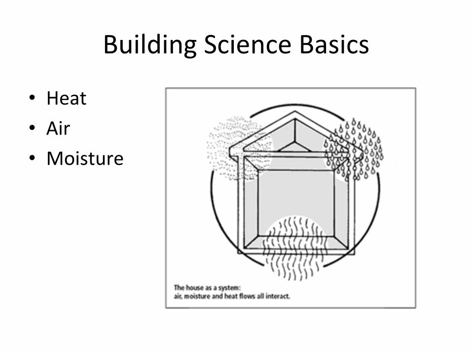
Building Science Basics
• Heat
• Air
• Moisture
Why Ventilate?
• People pollutants– human respiration (primarily CO2), body odor, water
vapor
• Building pollutants– VOC,s, combustion gases, radon, water vapor
• Activity pollutants– VOC’s, water vapor, odors
Goals of Mechanical Ventilation
• To provide an efficient exchange of air– system design, specification and installation
• To control moisture– identification of sources
• To provide improved indoor air quality– collection, removal and replacement of air
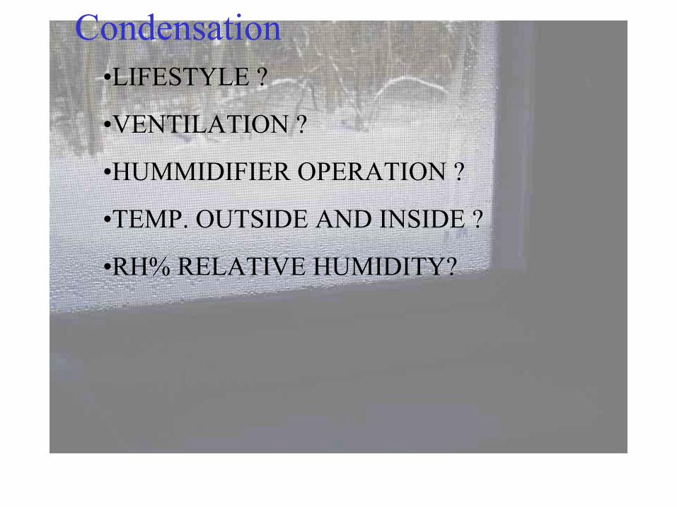
•LIFESTYLE ?
•VENTILATION ?
•HUMMIDIFIER OPERATION ?
•TEMP. OUTSIDE AND INSIDE ?
•RH% RELATIVE HUMIDITY?
Condensation
Section 1‐ Purpose
1. Defines the roles of the minimum requirement for mechanical and natural ventilation systems
2. Intended to provide acceptable indoor air quality in low rise residential buildings
Section 2‐ Scope
Type of BuildingSection 2
• All residential spaces for human occupancy
• Single family houses
• Multi family up to 3 stories
• Key word is intended for human occupancy
The Standard and Residential SpacesSection 2
Covered space that people normally enter include:• Living rooms• Bedrooms• Kitchens• Bathrooms• Hallways• Closets• Store rooms• Laundries • Basement
Standard and Residential Spaces
Other spaces within the building are not covered, these areas are listed below:
• Attics
• Crawl spaces
*NOTE: These spaces are not included in the ventilation calculation.
Section 3‐ Definitions
ASHREA Standard 62.2 ‐2010
• Section 3 of the actual standard has definitions not the user guide
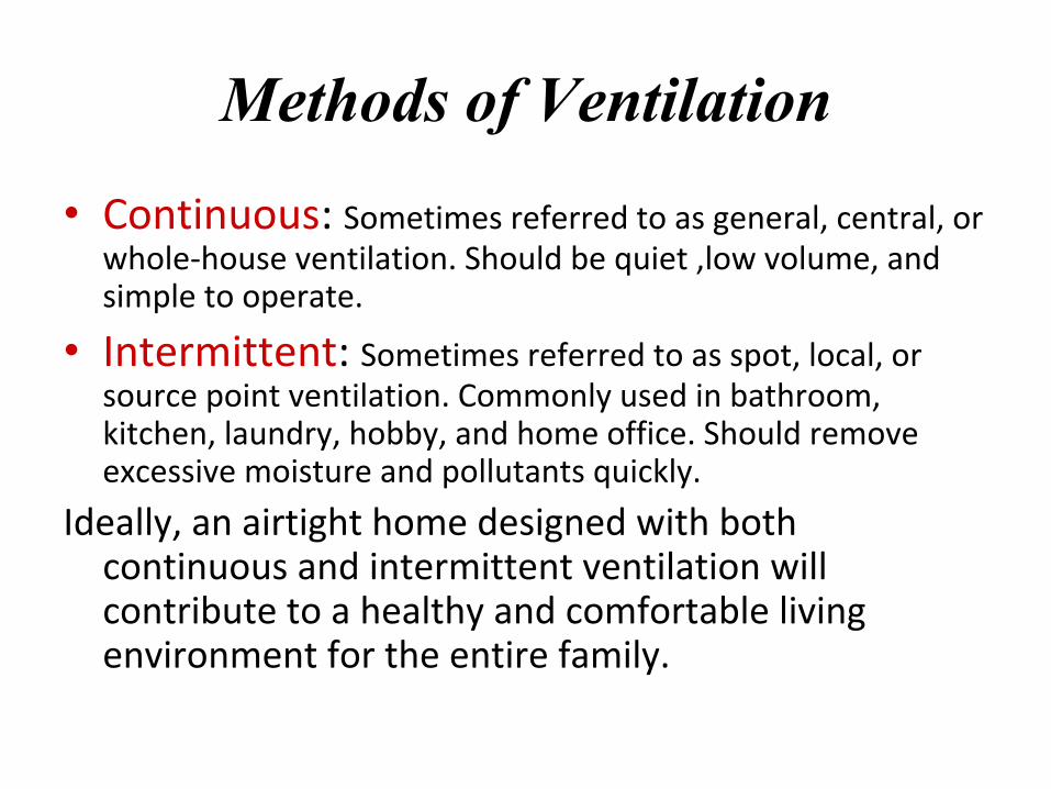
Methods of Ventilation
• Continuous: Sometimes referred to as general, central, or whole‐house ventilation. Should be quiet ,low volume, and simple to operate.
• Intermittent: Sometimes referred to as spot, local, or source point ventilation. Commonly used in bathroom, kitchen, laundry, hobby, and home office. Should remove excessive moisture and pollutants quickly.
Ideally, an airtight home designed with both continuous and intermittent ventilation will contribute to a healthy and comfortable living environment for the entire family.
Section 4 Whole – Building Ventilation
Index for Section 4
• 4.1 VENTILATION RATE• 4.1.1 DIFFERENT OCCUPANT DENSITY• 4.1.3 INFILTRATION CREDIT• 4.2 SYSTEM TYPES• 4.3 AIRFLOW MEASUREMENT• 4.4 CONTROL AND OPERATION• 4.5 DELIVERED VENTILATION• 4.6.2 VERY COLD CLIMATES
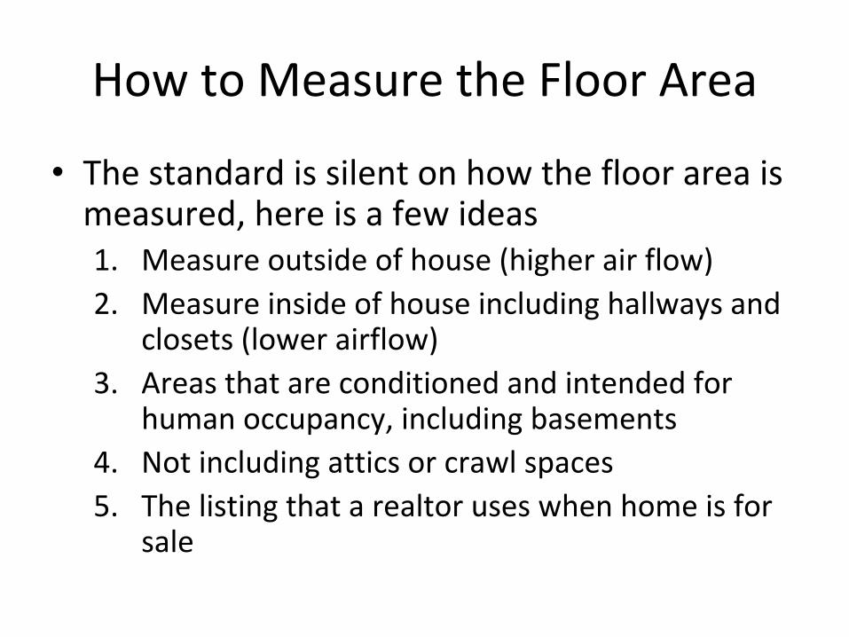
How to Measure the Floor Area
• The standard is silent on how the floor area is measured, here is a few ideas1. Measure outside of house (higher air flow)2. Measure inside of house including hallways and
closets (lower airflow)3. Areas that are conditioned and intended for
human occupancy, including basements4. Not including attics or crawl spaces5. The listing that a realtor uses when home is for
sale
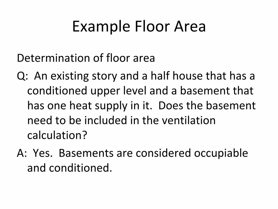
Example Floor Area
Determination of floor area
Q: An existing story and a half house that has a conditioned upper level and a basement that has one heat supply in it. Does the basement need to be included in the ventilation calculation?
A: Yes. Basements are considered occupiableand conditioned.
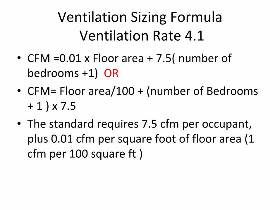
Ventilation Sizing FormulaVentilation Rate 4.1
• CFM =0.01 x Floor area + 7.5( number of bedrooms +1) OR
• CFM= Floor area/100 + (number of Bedrooms + 1 ) x 7.5
• The standard requires 7.5 cfm per occupant, plus 0.01 cfm per square foot of floor area (1 cfm per 100 square ft )
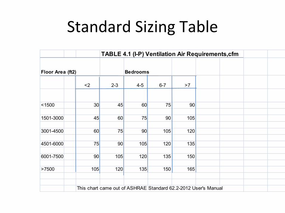
Standard Sizing TableTABLE 4.1 (I-P) Ventilation Air Requirements,cfm
Floor Area (ft2) Bedrooms
<2 2-3 4-5 6-7 >7
<1500 30 45 60 75 90
1501-3000 45 60 75 90 105
3001-4500 60 75 90 105 120
4501-6000 75 90 105 120 135
6001-7500 90 105 120 135 150
>7500 105 120 135 150 165
This chart came out of ASHRAE Standard 62.2-2012 User's Manual
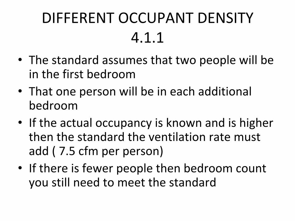
DIFFERENT OCCUPANT DENSITY4.1.1
• The standard assumes that two people will be in the first bedroom
• That one person will be in each additional bedroom
• If the actual occupancy is known and is higher then the standard the ventilation rate must add ( 7.5 cfm per person)
• If there is fewer people then bedroom count you still need to meet the standard
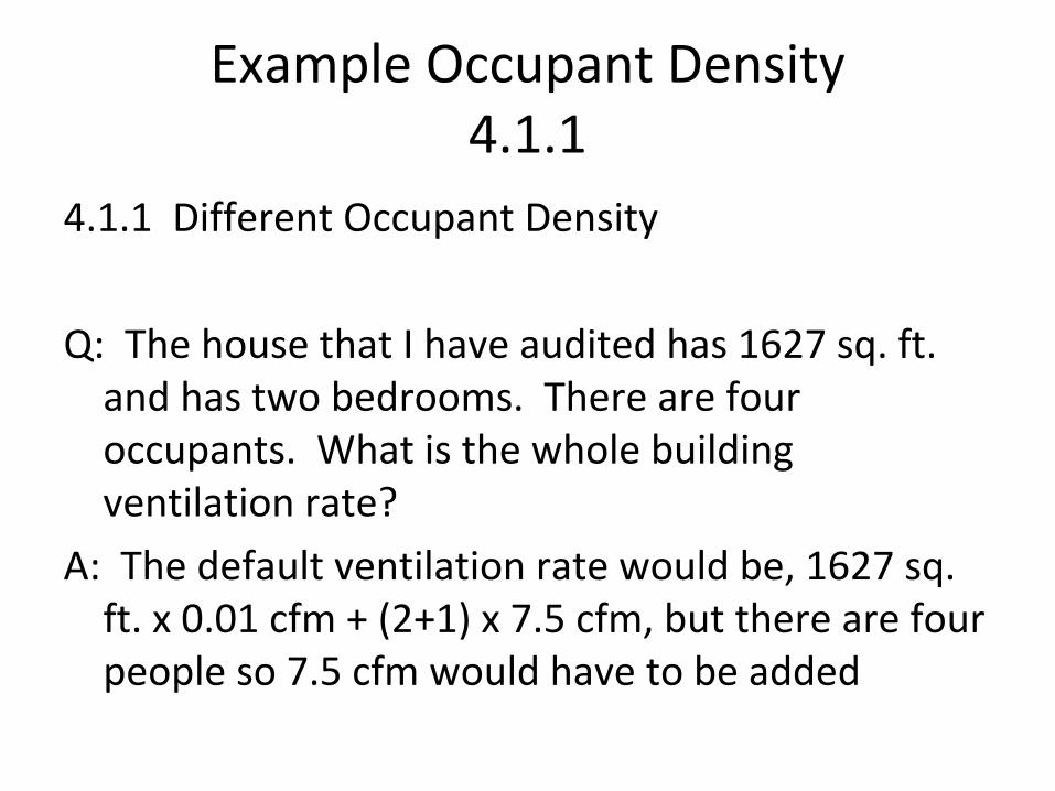
Example Occupant Density4.1.1
4.1.1 Different Occupant Density
Q: The house that I have audited has 1627 sq. ft. and has two bedrooms. There are four occupants. What is the whole building ventilation rate?
A: The default ventilation rate would be, 1627 sq. ft. x 0.01 cfm + (2+1) x 7.5 cfm, but there are four people so 7.5 cfm would have to be added
Infiltration Credit4.1.3
• The purpose is to allow a reduction in the required ventilation rate
• The ventilation standard assumes in addition to the mechanical ventilation an infiltration rate of 2 cfm per 100 of floor space
• This is based on a fairly tight house, attention to detail with air sealing
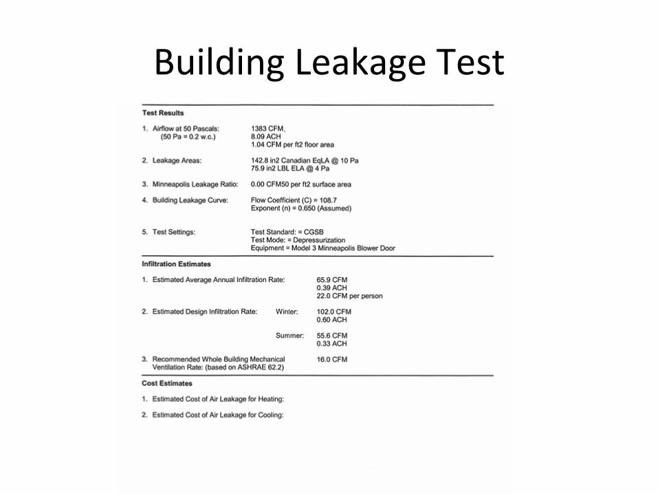
Building Leakage Test
Infiltration Credit4.1.3
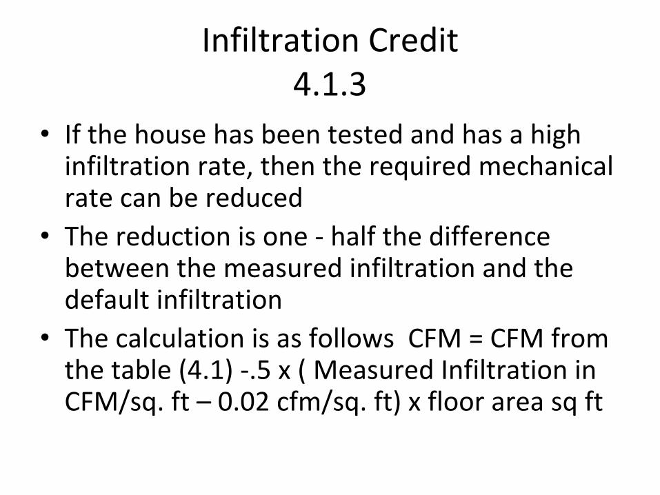
• If the house has been tested and has a high infiltration rate, then the required mechanical rate can be reduced
• The reduction is one ‐ half the difference between the measured infiltration and the default infiltration
• The calculation is as follows CFM = CFM from the table (4.1) ‐.5 x ( Measured Infiltration in CFM/sq. ft – 0.02 cfm/sq. ft) x floor area sq ft
System Type4.2
• The ventilation system is intended to provide adequate mechanical ventilation whenever the home is occupiable.
• This means system must be capable of providing desired ventilation 24 hours a day, 365 days a year
System Type4.2
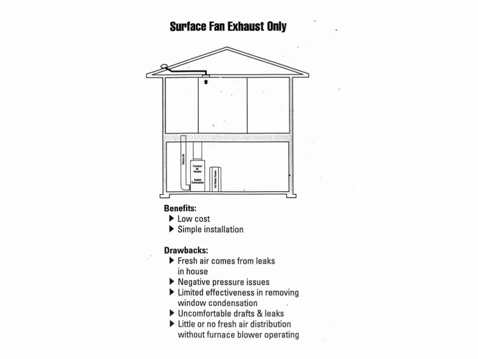
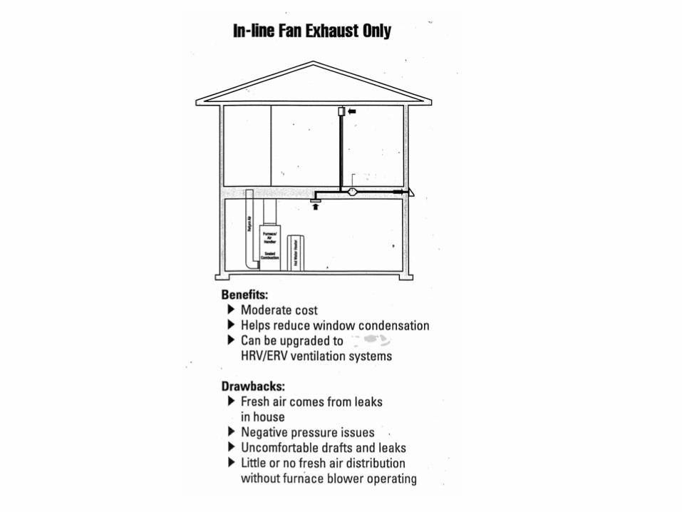
• The ventilation system can be1. Exhaust only
2. Supply only
3. A combination of supply and exhaust, this may or may not include a heat and/or energy recovery ventilator
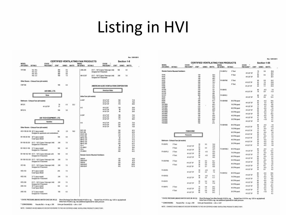
Listing in HVI
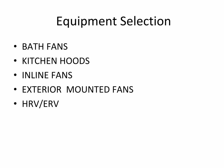
Equipment Selection
• BATH FANS
• KITCHEN HOODS
• INLINE FANS
• EXTERIOR MOUNTED FANS
• HRV/ERV
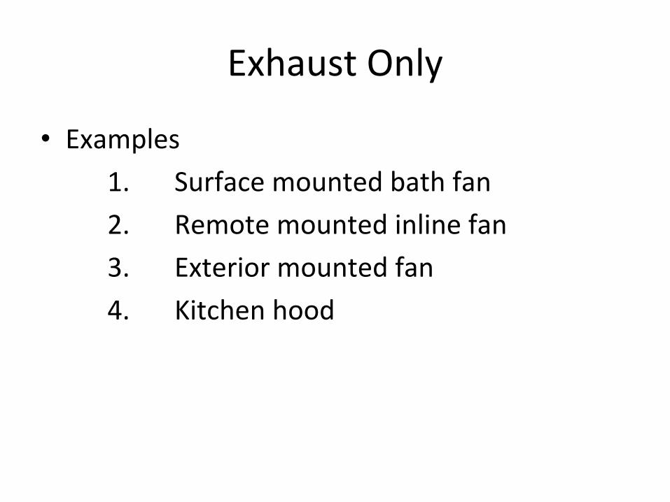
Exhaust Only
• Examples
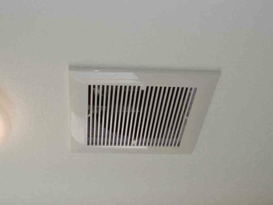
1. Surface mounted bath fan
2. Remote mounted inline fan
3. Exterior mounted fan
4. Kitchen hood
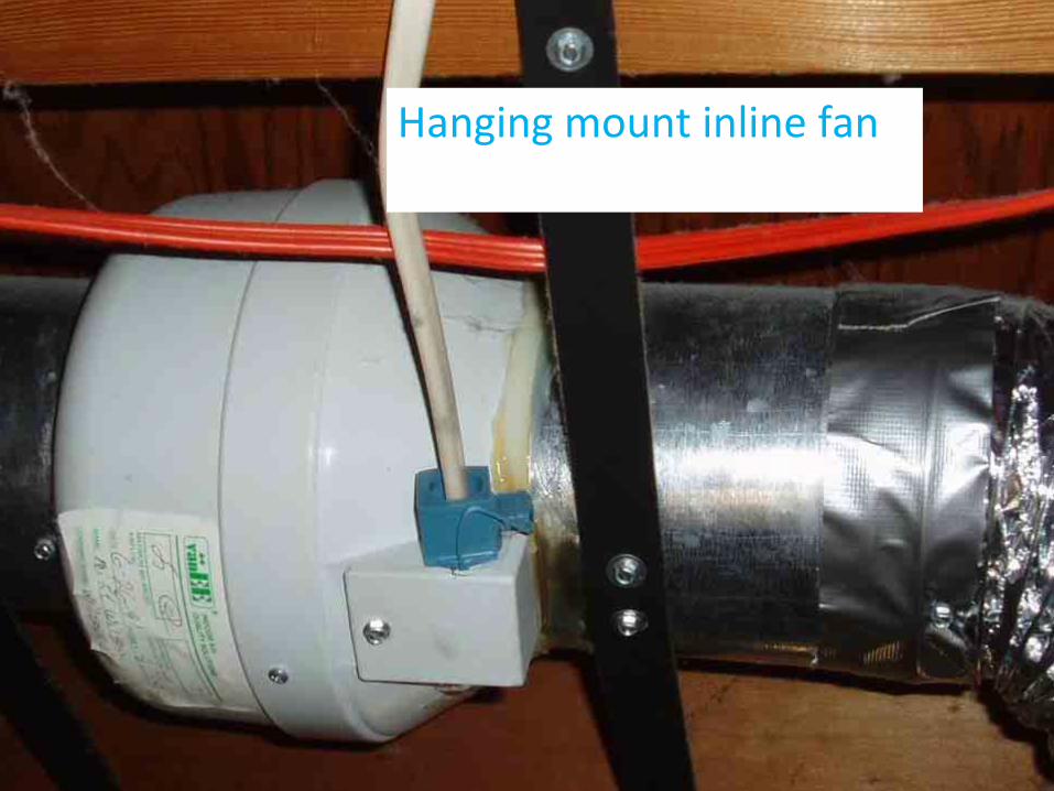
Hanging mount inline fan
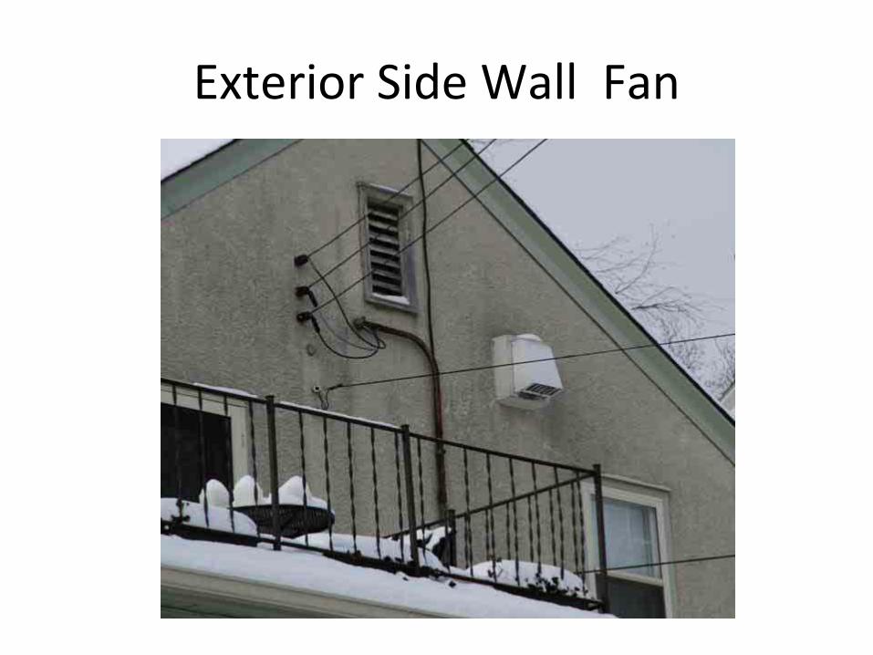
Exterior Side Wall Fan
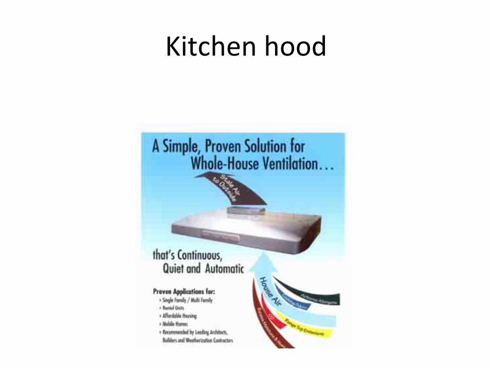
Kitchen hood
Supply Only
• Supply only ventilation in the northern climate is not very practical or common
• Various methods and installation types have been tried with poor results.
• Two installation types1. A duct could be hard connected to the return of
an air handler (furnace)2. A dedicated supply fan could pull in outside air
and supply it into the dwelling
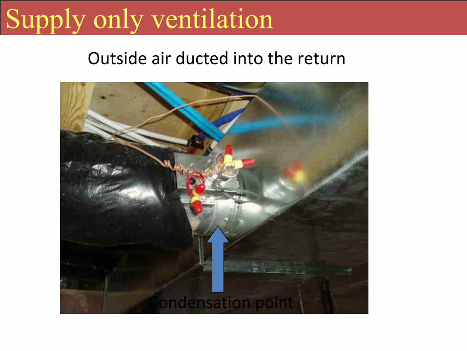
Outside air ducted into the return
Condensation point
Supply only ventilation
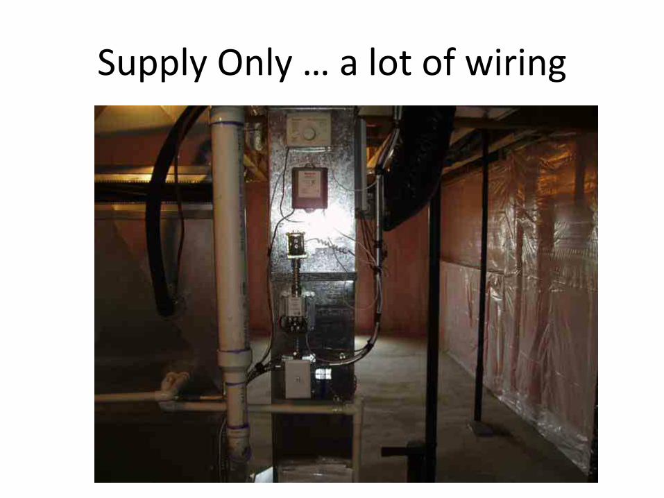
Supply Only … a lot of wiring
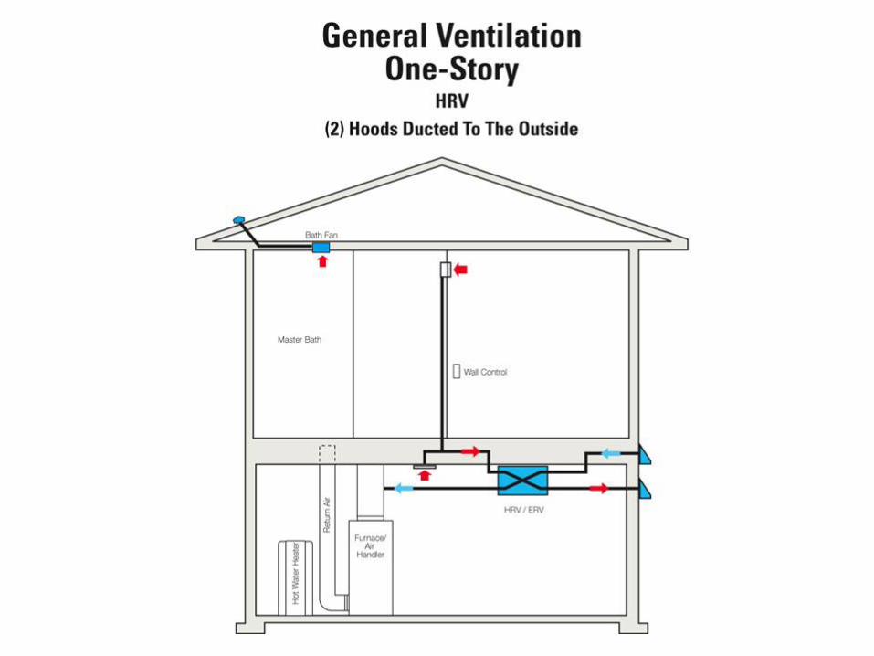
Combination Balanced Ventilation
• A common and accepted ventilation system for northern climates is Heat Recovery Ventilation/Energy Recovery Ventilation1. These systems can do both whole building and
local exhaust, depending unit and duct design
2. These system have two air streams that are fairly equal, making the system “balanced” to avoid either pressurization or depressurization
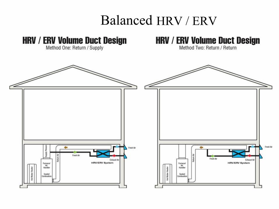
Balanced HRV / ERV
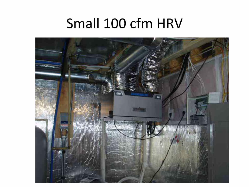
Small 100 cfm HRV
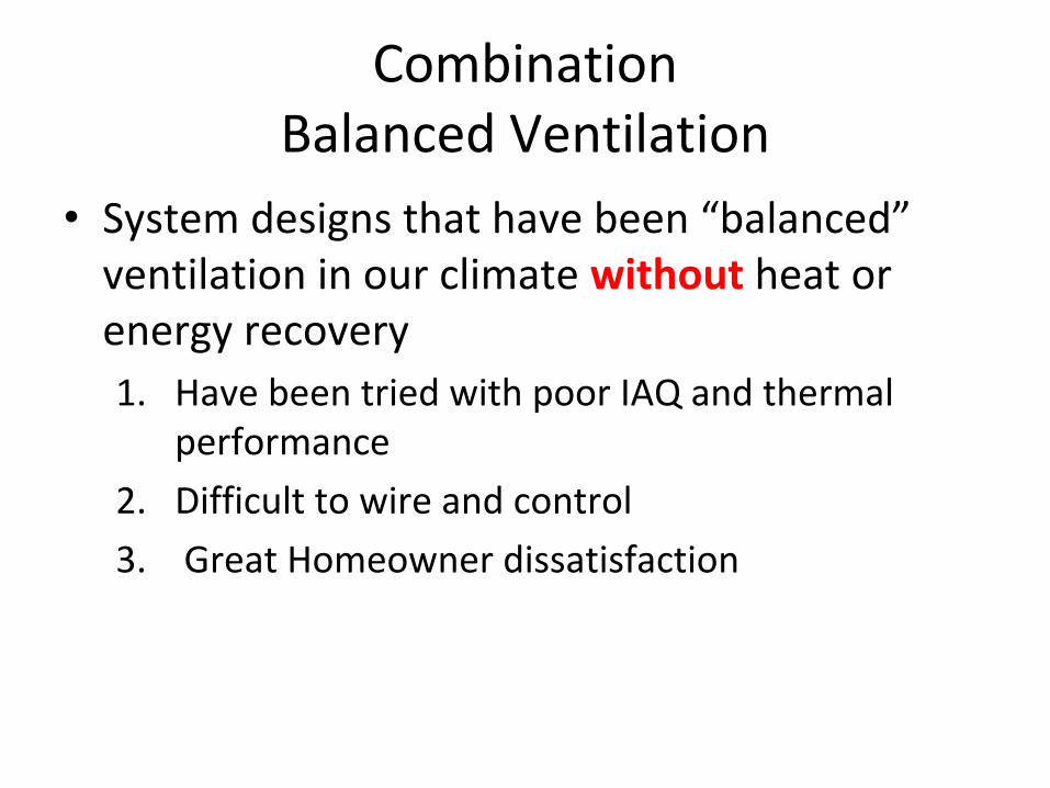
Combination Balanced Ventilation
• System designs that have been “balanced”ventilation in our climate without heat or energy recovery 1. Have been tried with poor IAQ and thermal
performance
2. Difficult to wire and control
3. Great Homeowner dissatisfaction
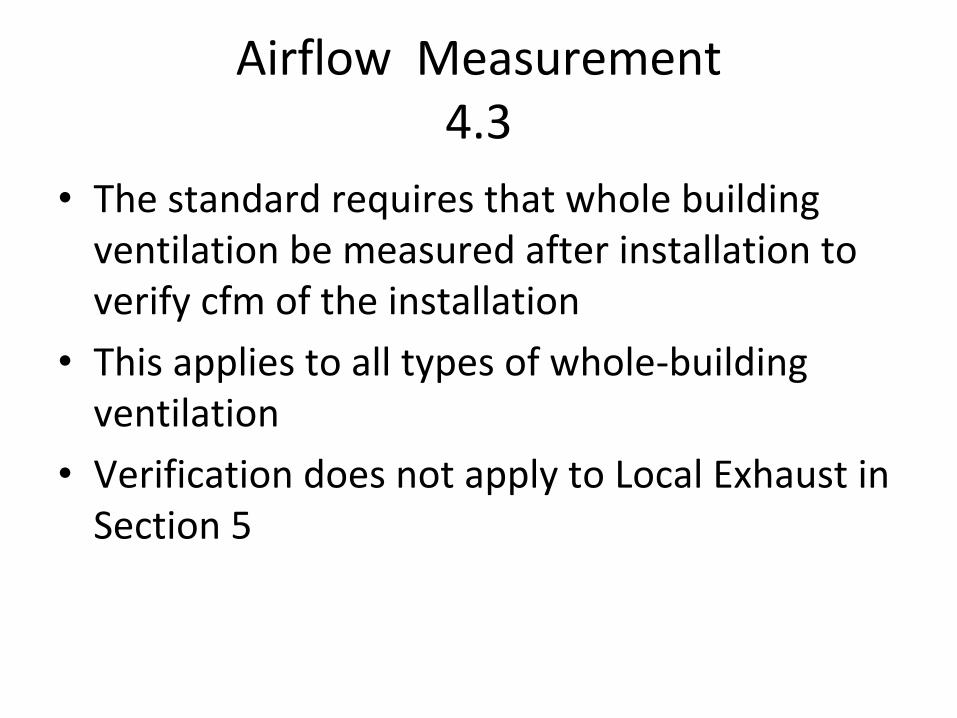
Airflow Measurement4.3
• The standard requires that whole building ventilation be measured after installation to verify cfm of the installation
• This applies to all types of whole‐building ventilation
• Verification does not apply to Local Exhaust in Section 5
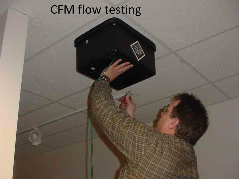
CFM flow testing
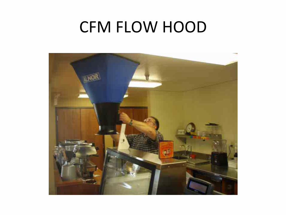
CFM FLOW HOOD
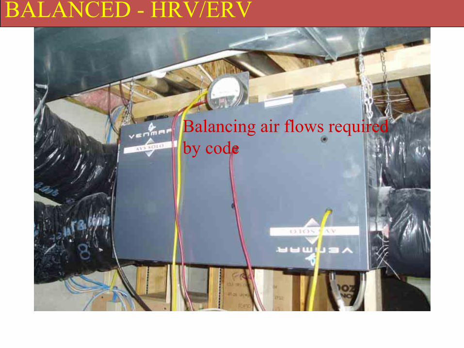
BALANCED - HRV/ERV
Balancing air flows required by code
Control and Operation4.4
• Two main requirements1. System has an override control which is readily
accessible to the occupant
The occupant has the choice to operate the ventilation system or not
2 . Section 4.1 is the rate for continuously operating system. The exception to this is the system may run intermittently
Control and Operation4.4
• Intermittent fan operation1. Air flow values from section 4.1 shall be provided
during each hour of operation, implying that the ventilation system runs continuously
2. The exception to this is that the system can run intermittently based on a timer, keep in mind when system runs it will be at a larger airflow to compensate for the “off – cycle” of the system
3. This means that during a 24 hour period, the amount of air flow (cfm) would be the same regardless if the system ran continuously or intermittently
Example control option
4‐G Control Options
Q: I plan to use a bathroom exhaust fan to provide the ventilation for a house. The fan is designed to be operated by a typical wall switch. Do I need to put a label on the wall plate to comply with the requirement that controls be “appropriately labeled”?
A: Yes. If the exhaust fan were serving only the local exhaustrequirements for the bathroom, then a label would not be required. Since the fan is providing whole‐building ventilation, a label is needed to inform the occupant of that.
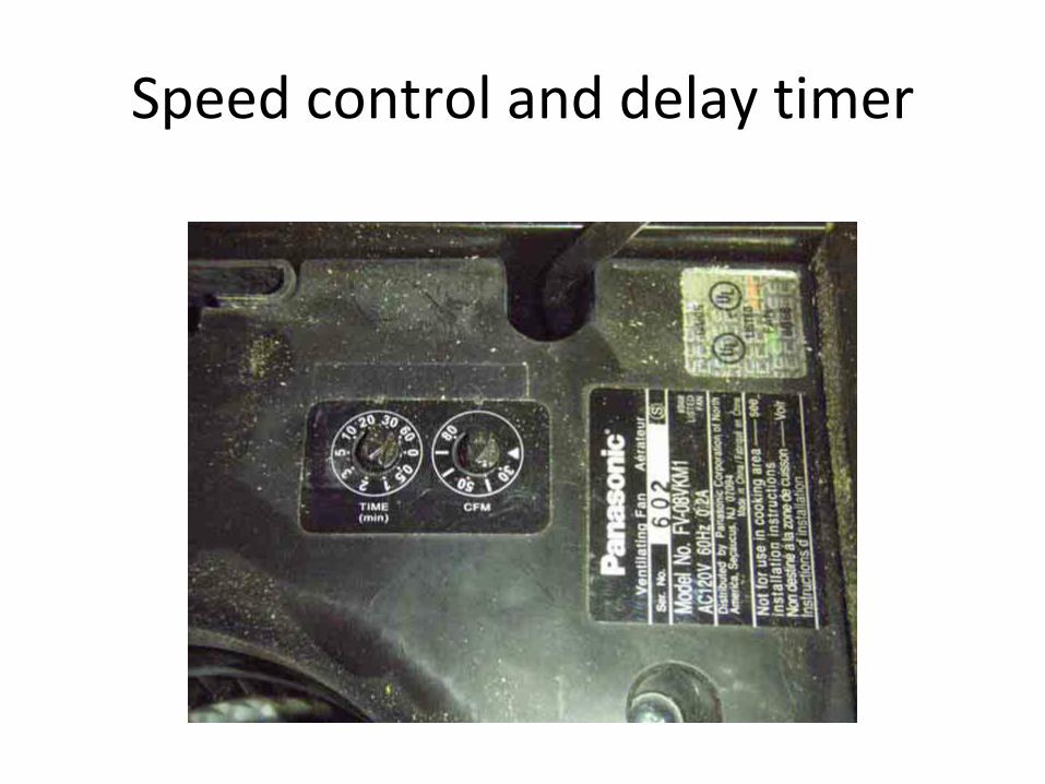
Speed control and delay timer
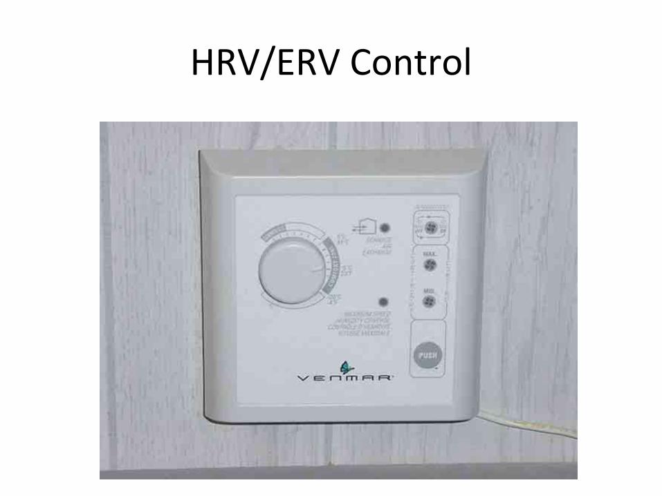
HRV/ERV Control
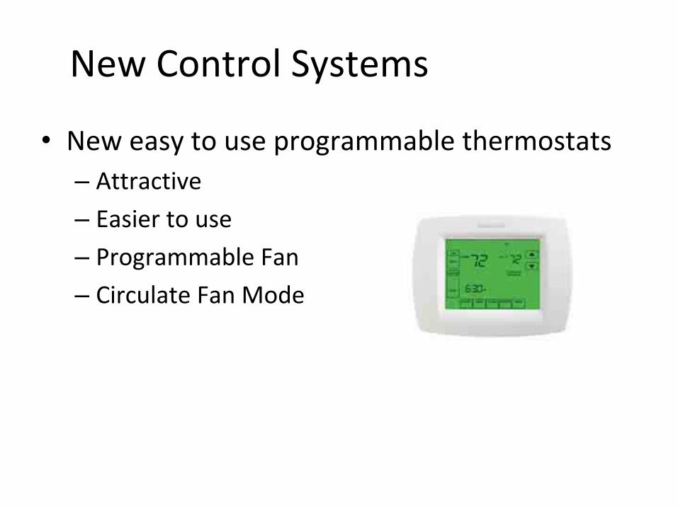
New Control Systems
• New easy to use programmable thermostats– Attractive
– Easier to use
– Programmable Fan
– Circulate Fan Mode
Delivered Ventilation4.5
• When using a combination ventilation (balanced) system, a HRV/ERV or dedicated supply/exhaust system, the ventilation rate is the larger of the two air streams
• The air flow rates cannot be added together to get credit for a higher ventilation rate
Very Cold Climates4.6.2
• In northern climates, there is a limitation to supply only ventilation due to potential pressurization– The supply air flow into the dwelling cannot be
greater then 7.5 cfm per 100 square feet of floor area
Section 5 Local Exhaust
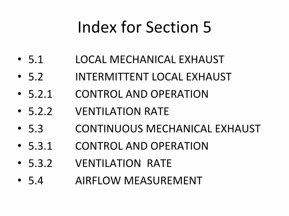
Index for Section 5
• 5.1 LOCAL MECHANICAL EXHAUST
• 5.2 INTERMITTENT LOCAL EXHAUST
• 5.2.1 CONTROL AND OPERATION
• 5.2.2 VENTILATION RATE
• 5.3 CONTINUOUS MECHANICAL EXHAUST
• 5.3.1 CONTROL AND OPERATION
• 5.3.2 VENTILATION RATE
• 5.4 AIRFLOW MEASUREMENT
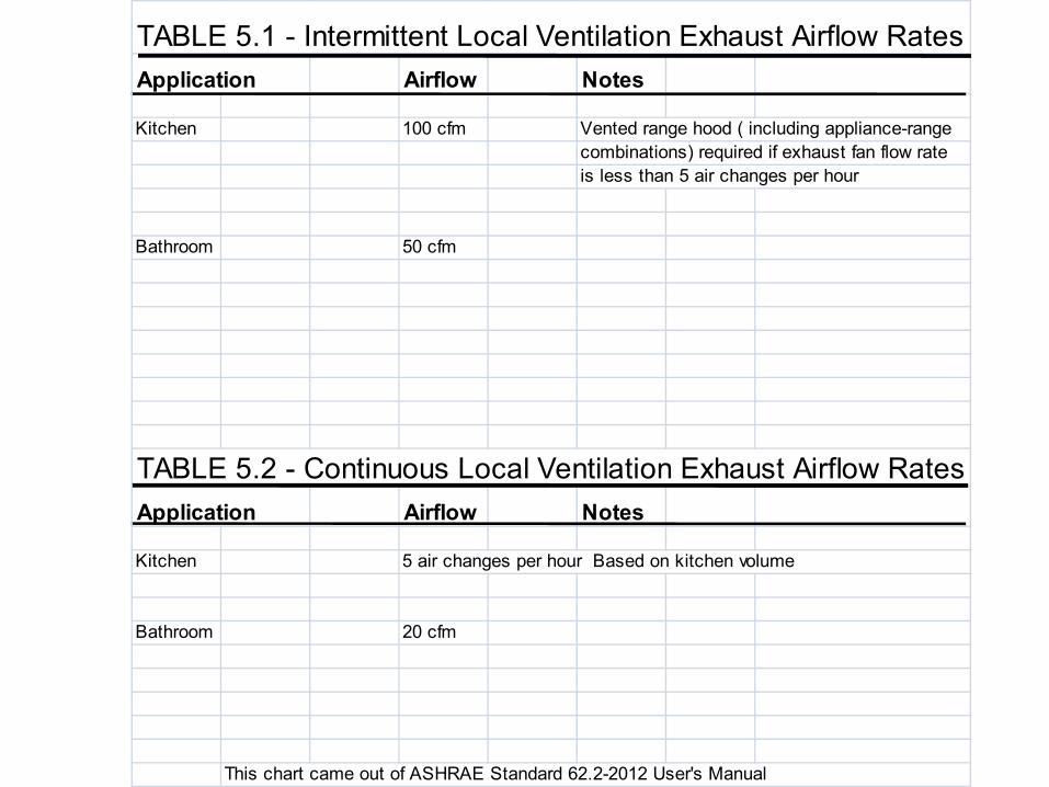
TABLE 5.1 - Intermittent Local Ventilation Exhaust Airflow RatesApplication Airflow Notes
Kitchen 100 cfm Vented range hood ( including appliance-rangecombinations) required if exhaust fan flow rateis less than 5 air changes per hour
Bathroom 50 cfm
TABLE 5.2 - Continuous Local Ventilation Exhaust Airflow RatesApplication Airflow Notes
Kitchen 5 air changes per hour Based on kitchen volume
Bathroom 20 cfm
This chart came out of ASHRAE Standard 62.2-2012 User's Manual
Local Exhaust5.1
• Local mechanical exhaust shall be installed in each kitchen and bathroom– This part of the standard shall be met in either of
the following two waysa) Intermittent mechanical exhaust system
b) Continuous mechanical exhaust system
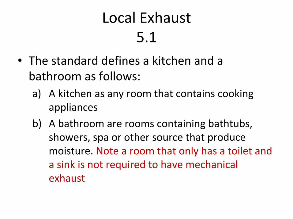
Local Exhaust5.1
• The standard defines a kitchen and a bathroom as follows:a) A kitchen as any room that contains cooking
appliances
b) A bathroom are rooms containing bathtubs, showers, spa or other source that produce moisture. Note a room that only has a toilet and a sink is not required to have mechanical exhaust
Example Local Exhaust
5a Local Exhaust Required for Half Bath
Q: The house I am working in has two and a half baths. Is local exhaust required for the half bath?
A: No. Local exhaust is required only for bathrooms with a tub, shower or other moisture producing sources.
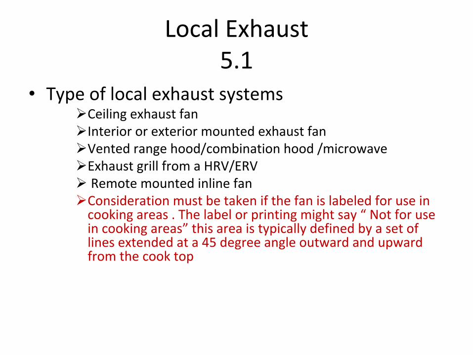
Local Exhaust5.1
• Type of local exhaust systemsCeiling exhaust fanInterior or exterior mounted exhaust fanVented range hood/combination hood /microwave Exhaust grill from a HRV/ERV Remote mounted inline fan
Consideration must be taken if the fan is labeled for use in cooking areas . The label or printing might say “ Not for use in cooking areas” this area is typically defined by a set of lines extended at a 45 degree angle outward and upward from the cook top
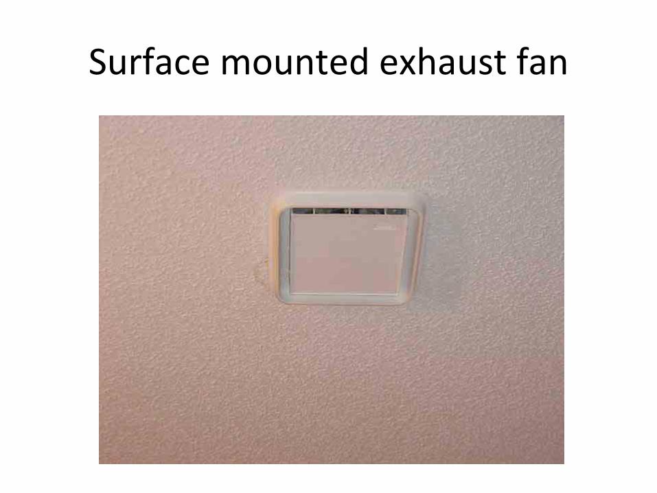
Surface mounted exhaust fan
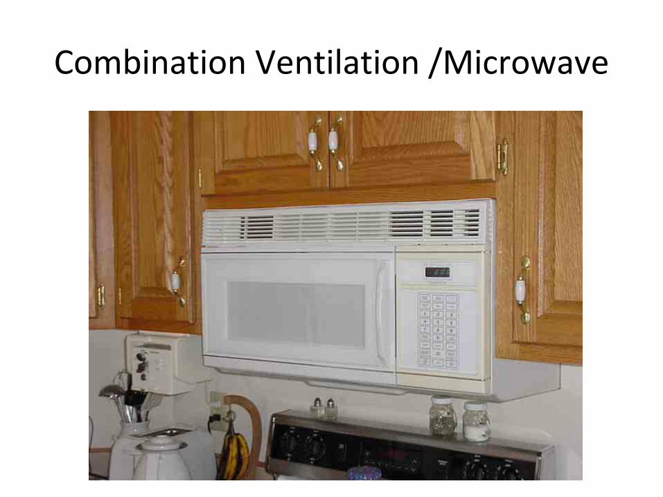
Combination Ventilation /Microwave
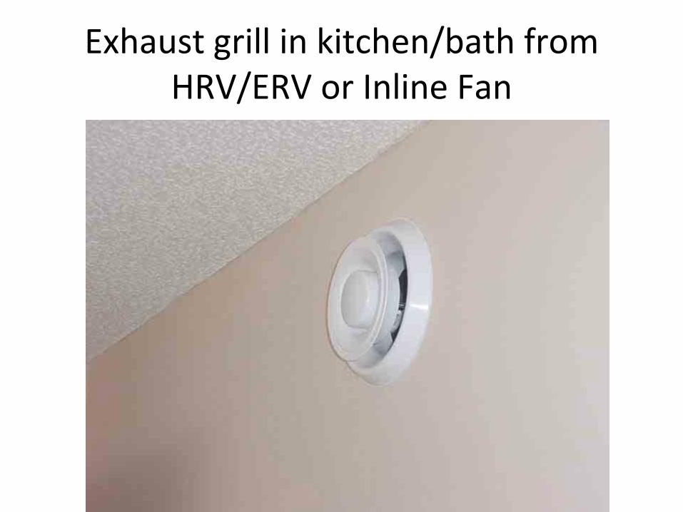
Exhaust grill in kitchen/bath from HRV/ERV or Inline Fan
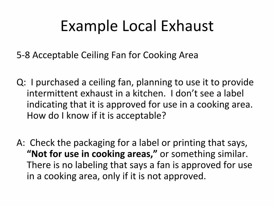
Example Local Exhaust
5‐8 Acceptable Ceiling Fan for Cooking Area
Q: I purchased a ceiling fan, planning to use it to provide intermittent exhaust in a kitchen. I don’t see a label indicating that it is approved for use in a cooking area. How do I know if it is acceptable?
A: Check the packaging for a label or printing that says, “Not for use in cooking areas,” or something similar. There is no labeling that says a fan is approved for use in a cooking area, only if it is not approved.
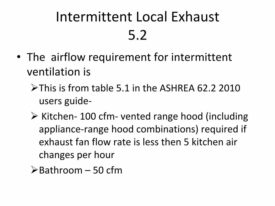
Intermittent Local Exhaust5.2
• The airflow requirement for intermittent ventilation is
This is from table 5.1 in the ASHREA 62.2 2010 users guide‐
Kitchen‐ 100 cfm‐ vented range hood (including appliance‐range hood combinations) required if exhaust fan flow rate is less then 5 kitchen air changes per hour
Bathroom – 50 cfm
Intermittent Local Exhaust5.2
• The standard requires that intermittent exhaust fans be designed to be operated by the occupant
• This means the control be accessible and obvious
Control and Operation 5.2.1
• Control and operation– The choice of the control is left up to the designer.
– Common controls include
• Manual switch, multi speed controls, delay shutoff function, humidistat, occupant sensors, combine switching
Ventilation Rate5.2.2
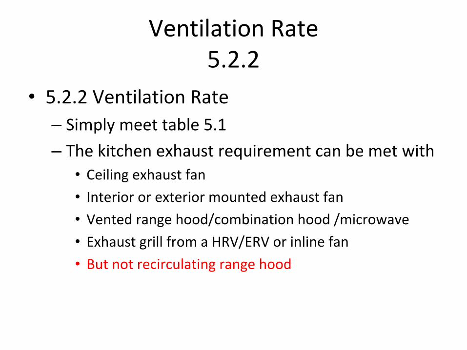
• 5.2.2 Ventilation Rate– Simply meet table 5.1
– The kitchen exhaust requirement can be met with• Ceiling exhaust fan
• Interior or exterior mounted exhaust fan
• Vented range hood/combination hood /microwave
• Exhaust grill from a HRV/ERV or inline fan
• But not recirculating range hood
Continuous Mechanical Exhaust5.3
• The standard allows the designer to install a local exhaust system that operates continuously and automatically
• The continuously local exhaust may be a part of the whole building ventilation system
Control and Operation5.3.1
• The system shall be designed to operate during all occupied hours.
• Readily assessable override control must be provided to the occupant
Ventilation Rate5.3.2
• This section simply requires the ventilation rate be met by airflow rate shown on table 5.2 or
Kitchen needs 5 air changes per hour based on kitchen volume
Bathroom needs 20 cfm
Ventilation Rate5.3.2
• The minimum delivered ventilation shall be at least the amount indicated in table 5.2 during each hour of operation
Airflow Measurement5.4
• To make sure that the standard is met, it is required that the installed fan be measured for airflow. The measurement must be made using a flow hood, flow grid or airflow measuring device
Airflow Measurement5.4
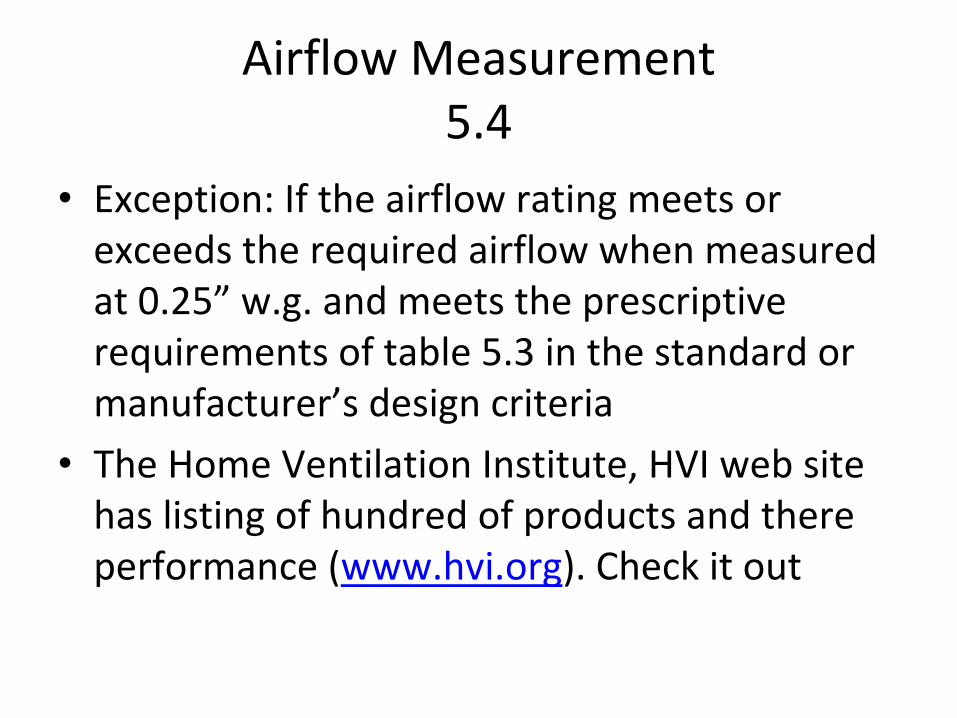
• Exception: If the airflow rating meets or exceeds the required airflow when measured at 0.25” w.g. and meets the prescriptive requirements of table 5.3 in the standard or manufacturer’s design criteria
• The Home Ventilation Institute, HVI web site has listing of hundred of products and there performance (www.hvi.org). Check it out
Section 6 Other Requirements
Index for Section 6 • 6.1 ADJACENT SPACES
• 6.2 INSTRUCTIONS AND LABELING
• 6.3 CLOTHES DRYERS
• 6.4 COMBUSTION AND SOLID FUEL BURNING APPLIANCES
• 6.5 AIRTIGHTNESS REQUIREMENTS
• 6.5.1 GARAGES
• 6.5.2 SPACE – CONDITIONING SYSTEM DUCTS
Index for Section 6
• 6.6 VENTILATION OPENING AREA
• 6.6.1 HABITABLE SPACES
• 6.2.2 TOILETS AND UTILITY ROOMS
• 6.7 MINIMUM FILTRATION
• 6.8 AIR INLETS
• 6.8.1 VENTILATION OPENING
Adjacent Spaces6.1
• The intent of the standard is to use air from outside for ventilation
• Measurements shall be taken to minimize air movement across the building shell separating dwelling unit, and to dwelling unit garages, unconditioned crawl spaces, and unconditioned attic
• Supply and balanced ventilation system shall provide ventilation air from the outdoors
Instructions and Labeling6.2
• Information (instructions) on what the ventilation system is supposed to do and how to operate it shall be provided to the owner and occupant.
• Controls shall be labeled as to their function, no specific wording is mandated
Clothes Dryers6.3
• Clothes dryers shall be exhausted directly to the outdoors
Combustion and Solid‐fuel Burning Appliances
6.4• This part of the standard discuses
atmospherically (natural draft) appliances and prevention back‐drafting
• Proper appliance installation according to the code or standard and manufactures installation should provide a good margin of safety for protection against back‐drafting
Combustion and Solid‐fuel Burning Appliances
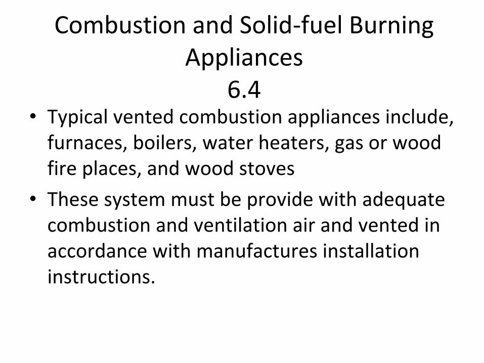
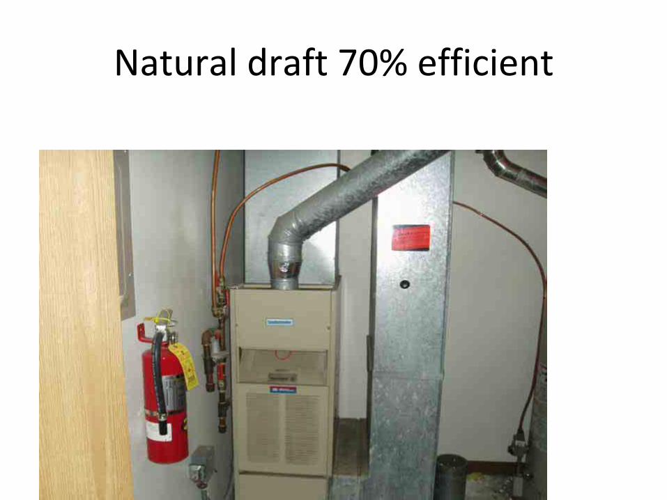
6.4• Typical vented combustion appliances include,
furnaces, boilers, water heaters, gas or wood fire places, and wood stoves
• These system must be provide with adequate combustion and ventilation air and vented in accordance with manufactures installation instructions.
Combustion air
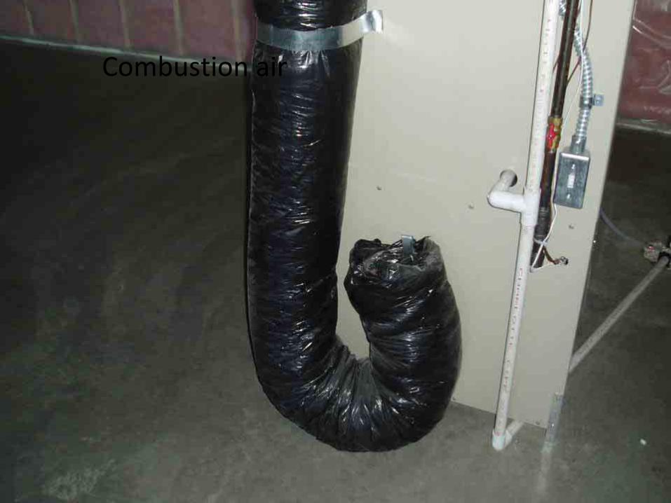
Natural draft 70% efficient
FIRE PLACES
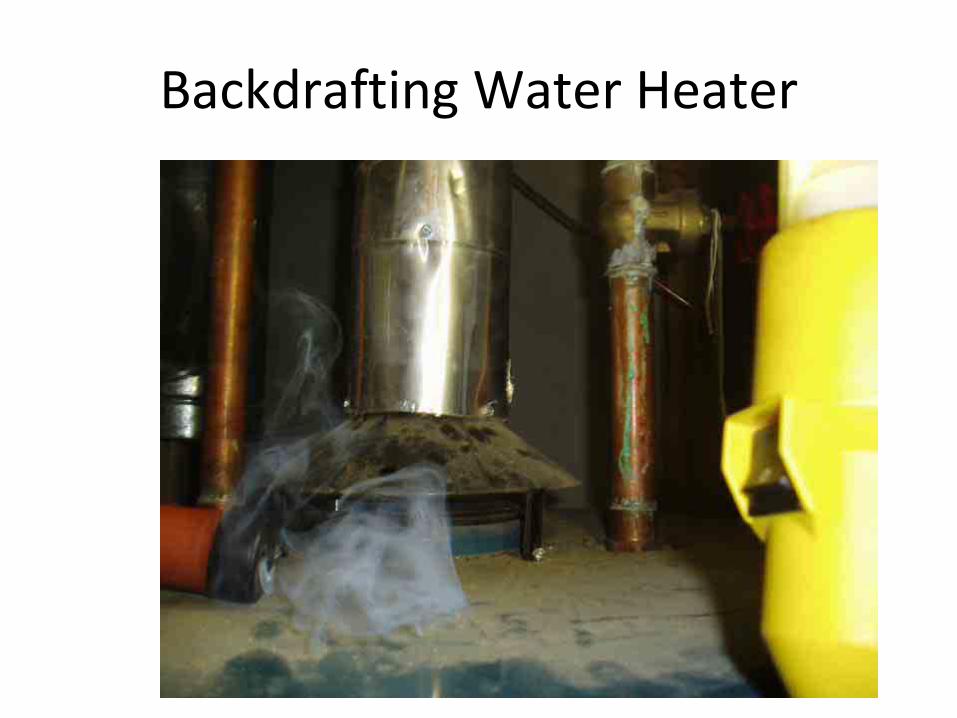
Backdrafting Water Heater
CAZ Testing
• Acceptable (BPI or equivalent) methods of Combustion Air Zone (CAZ) testing need to used when natural draft equipment is with in the stucture
Combustion and Solid‐fuel Burning Appliances
6.4• This calculation is applicable when
atmospherically vented combustion or a solid fuel burning appliance is located with in the pressure boundary.
• When the net flow of the two largest exhaust fans exceeds 15 cfm/100sq ft or (.15 X sq ft) of occupiable space the following needs to occur:
The net exhaust flow needs to reduced Outdoor make up air is needed to be supplied to
house Combination of both
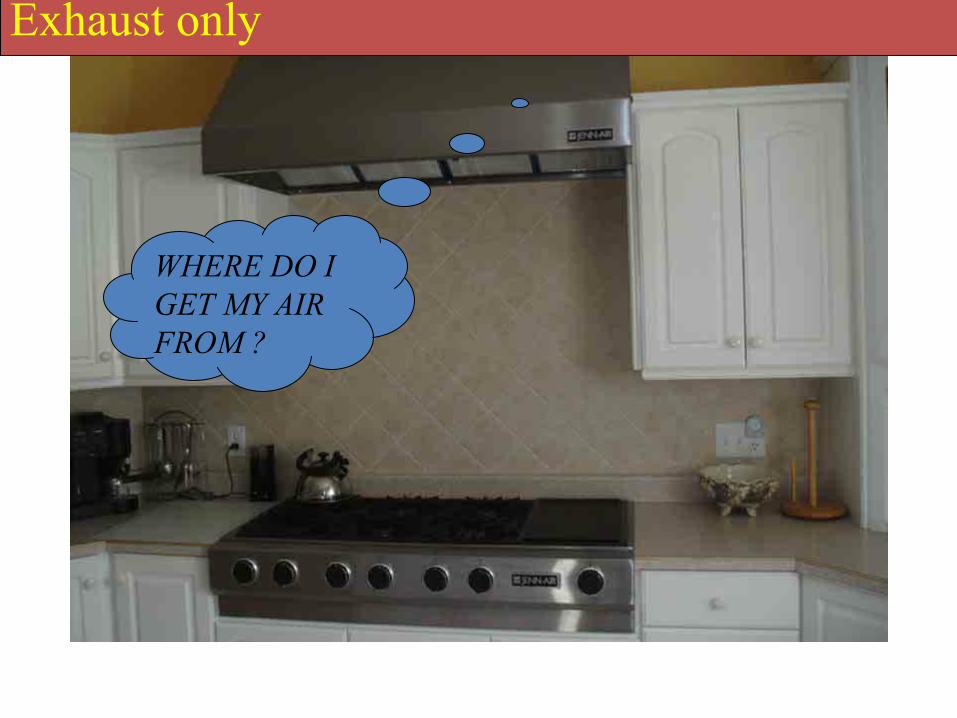
WHERE DO I GET MY AIR FROM ?
Exhaust only
Air Tightness Requirements6.5.1 Garages
• Garages, attached to the house
• Prevent migration of contaminates entering the house
• Air sealing needs to occur at common air leakage areas
• Doors between garages and occupiablespaces shall be gasketed
Air Tightness Requirements6.5.2 Space –Conditioning system
ducts• All air distribution joints outside the pressure
boundary shall be sealed
• Air distribution systems shall not serve both occupiable spaces and garage area
• If duct work is out side of the pressure boundary it can not leak more then of 6% of total airflow when measured at .1 wc (25pa)
Air Tightness Requirements6.5.2 Space –Conditioning system
ducts• Leakage tests must be in accordance with
California Title 24 (2001) or equivalent.
• Method D of ANSI/ASTM E1554 is specially cited as an equivalent test procedure
Minimum Filtration 6.7
• Merv rating of 6 or better needs to be used for mechanical systems that supply air to occupiable spaces
• Outdoor air needs to be filtered
• This filtration requirement applies to air handling (heating and cooling) systems with 10 feet of duct work or more
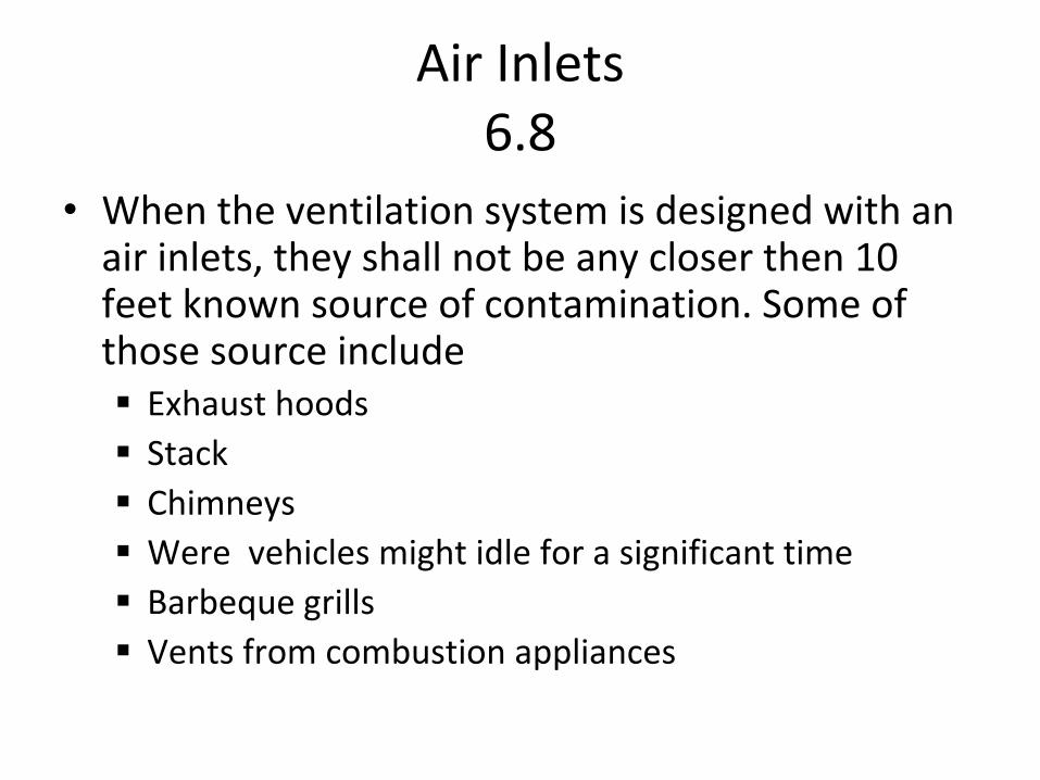
Air Inlets6.8
• When the ventilation system is designed with an air inlets, they shall not be any closer then 10 feet known source of contamination. Some of those source include
Exhaust hoodsStackChimneysWere vehicles might idle for a significant timeBarbeque grillsVents from combustion appliances
Section 7 Air‐Moving Equipment
Air Moving Equipment7.1
• 7.1 Selection and Installation; There is several rating and standards that 7.1 refers to, they look at sound, performance, air flow and aerodynamics of air moving equipment
• You must review and follow manufacture’s installation instruction
Sound Rating for Fans7.2
• The sound requirement applies to surface mounted fans
• An exception to the sound requirement would be these type of systems
HRV/ERVSInline fansRemote fansHVAC air handlers
These system need to have at least 4 feet of ductwork between the fan and the intake grille
Whole‐Building or Continuous Ventilation Fans
7.2.1• These fans shall be rated for sound at a
maximum of 1.0 Sone
Intermittent Local Exhaust Fans7.2.2
• These fans shall be rated for sound at a maximum of 3.0 Sone, unless their maximum rated airflow exceeds 400 cfm
Multi‐branch Exhaust Ducting7.3
• If there is more then one exhaust fan that uses common duct work, back draft dampers need to be installed to prevent recirculation
APPENDIX A
EXISISTING BUILDINGS
APPENDIX AEXISISTING BUILDINGS
• This is an alternative method for existing buildings to meet 62.2
• In general, the whole‐building ventilation rate, as determined from section 4.1 of the standard , is increased to compensate when it is impractical to provide kitchen or bathroom exhaust equipment
APPENDIX AEXISISTING BUILDINGS
• SECTION A2 Whole‐Building Mechanical Ventilation Rate
• Two points 1. Increase the whole building ventilation when
local can’t be meet
2. If building is leaky (must be measured) a reduction in ventilation may occur
Initial Room Airflow DeficitA 3.1
• This number is determined by comparing the exhaust flow of existing equipment and requirement of table 5.1
The measured or rated flow
Example
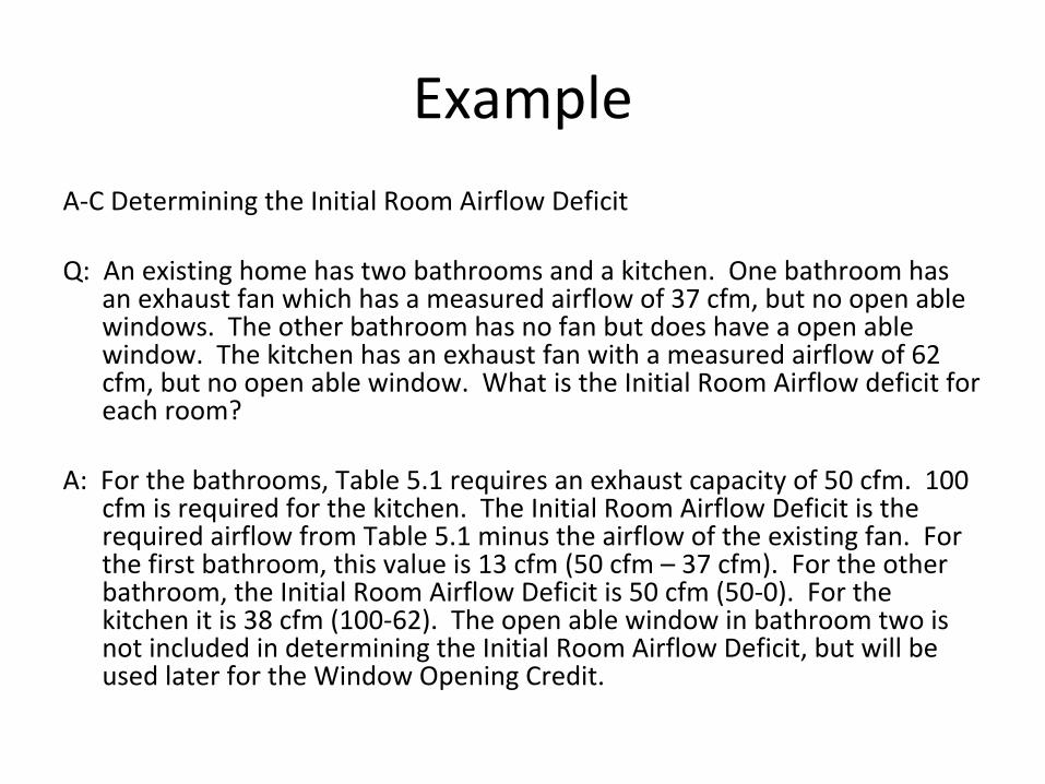
A‐C Determining the Initial Room Airflow Deficit
Q: An existing home has two bathrooms and a kitchen. One bathroom has an exhaust fan which has a measured airflow of 37 cfm, but no open able windows. The other bathroom has no fan but does have a open able window. The kitchen has an exhaust fan with a measured airflow of 62 cfm, but no open able window. What is the Initial Room Airflow deficit for each room?
A: For the bathrooms, Table 5.1 requires an exhaust capacity of 50 cfm. 100 cfm is required for the kitchen. The Initial Room Airflow Deficit is the required airflow from Table 5.1 minus the airflow of the existing fan. For the first bathroom, this value is 13 cfm (50 cfm – 37 cfm). For the other bathroom, the Initial Room Airflow Deficit is 50 cfm (50‐0). For the kitchen it is 38 cfm (100‐62). The open able window in bathroom two is not included in determining the Initial Room Airflow Deficit, but will be used later for the Window Opening Credit.
Window Opening CreditA 3.2
• One credit per room (Kitchen or Bathroom)
• 20 cfm reduction per room (Kitchen or Bathroom) if it has an openable window
Required Additional AirflowA 3.2
• The final step in the calculating the adjusted mechanical ventilation rate is to add the Initial Room Airflow Deficit for each kitchen or bathroom, subtract 20 cfm for each of those rooms with an openable window, then divide that total by four. Then go to step 4 in the next slide
APPENDIX AEXISISTING BUILDINGS
1. Add initial room air deficit for applicable kitchens and bathrooms
2. Subtract 20 cfm for each kitchen and bathroom with an open able window
3. Divide the total by four. The results is the required additional airflow
4. Add to the whole‐building mechanical ventilation rate determined in Section 4.1
5. Deduct the infiltration credit determined in section 4.1.3

Thank you for your time
DAKOTA SUPPLY GROUP
• “To be the leading supplier of quality products and services for durable, energy efficient and healthier homes”
• www.dakotasupplygroup.com• Toll Free 800‐652‐9784


![2012 IECC PerformanceTesting: Lessons from the Duct and ......(2012 IRC mandates the prescriptive ventilation tables, but not the formulas, of ASHRAE 62.2 [2010]). In section R303.4](https://img.pdfslide.us/doc/110x75/613d4139984e1626b65778cb/2012-iecc-performancetesting-lessons-from-the-duct-and-2012-irc-mandates.jpg)