Embed Size (px)
Citation preview
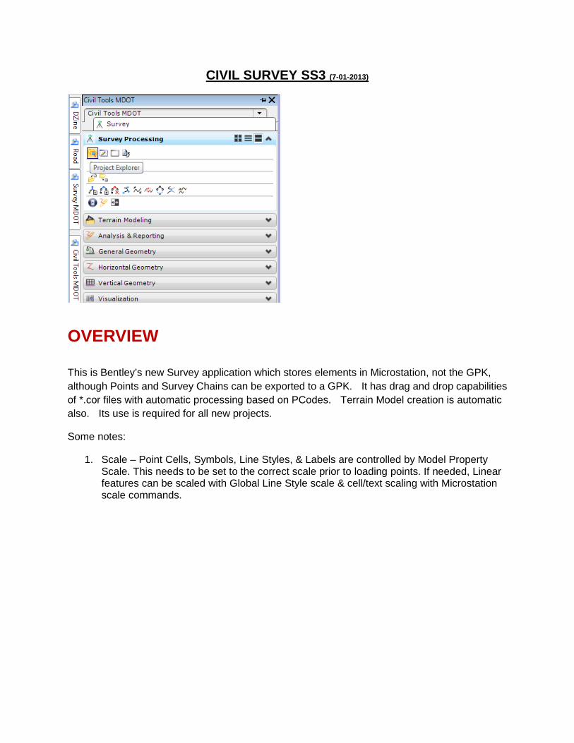
CIVIL SURVEY SS3 (7-01-2013)
OVERVIEW
This is Bentley’s new Survey application which stores elements in Microstation, not the GPK, although Points and Survey Chains can be exported to a GPK. It has drag and drop capabilities of *.cor files with automatic processing based on PCodes. Terrain Model creation is automatic also. Its use is required for all new projects.
Some notes:
1. Scale – Point Cells, Symbols, Line Styles, & Labels are controlled by Model Property Scale. This needs to be set to the correct scale prior to loading points. If needed, Linear features can be scaled with Global Line Style scale & cell/text scaling with Microstation scale commands.

2. Settings -> Standard Settings
NOTE: Most of the settings for Survey are established in the file civilfeatures.dgnlib. These settings are moved into the DGN file you are working on and can be accessed through Project Explorer. Civil Standards tab & Features (You would generally not modify this.) ->

Pcodes are established under Project Explorer-> Civil Standards tab-> Feature Settings -> rwdsvy by Right Clicking & Linking rwdsvy.xml. When you load Survey Points in file, the PCODES that are processed show up under the DGN in Project Explorer. You can access this to display/undisplay certain groups of points as shown below:
3. Workspace Preferences:

Linking Codes Linking Codes are shown below. The big change from GeoPak Survey is that you cannot have consecutive Start Codes (L). You start a Linear Feature with L and do not assign this code on subsequent shots of the same PCODE. When you get to the last shot of the linear feature, you enter EL. An example format follows the table below. Control Codes provide the ability to enable special treatment of specific points to be automatically implemented during the data processing.
Control codes must be assigned after the Field code. Control codes can only be Alpha values. Control and Linking codes can both be used on the same point as long as the Control code is last. Control codes must be separated from
LIKING CODES Start – used to begin creating a Linear Feature StartPC – Starts a linear feature in Arc Mode
ArcPC – Used to specify the beginning of a tangential arc or curve within a Linear Feature
NonTanPC – Used to specify the beginning of a non-tangential arc or curve within a Linear Feature
ArcSingle – Creates a three point arc with previous and next points (does not work at beginning or end of a Linear Feature)
ArcToArc – Ends previous tangent arc and begins another tangent arc (must be preceded by ArcPC)
NonTanPT – Specifies the end of a non-tangential arc or curve within a Linear Feature
ArcPT – Specifies the end of a tangential arc or curve within a Linear Feature
ArcToggle – Toggles between NonTanPC and NonTanPT (depends on pairing)
End – Ends the linear feature (not necessary in most cases)
CloseShape – Closes the ends of the linear feature by adding right angle at both
CONTROL CODES CircleDiameter – Draws a circle of specified diameter around this point (must be within Linear Feature)
CircleRadius – Draws a circle with specified radius around this point (must be within Linear Feature)
RectangleWidth – Draws a rectangle from two points and specified width (must be within Linear Feature)
TapeDistance – Allows field measured distances to be applied to the Linear Feature – All measurements are applied 90 degrees from previous segment. Positive values turn right and negative values turn left. (must be within Linear Feature)
JoinPoint – Joins this point to specified point name (does NOT have to be in linear feature)
NewTemplate – Same as InRoads TMPL – Consecutive Start codes will get this linear feature paralleled and translated based off of initial points
Elevation – Sets the Elevation of this point
UpDown – Changes final elevation coordinate of point by value entered
LeftRight – Changes final coordinate of point by adjusting left (-) or right (+) of measured observation by value entered
FrontBack – Changes final coordinate of point by adding or subtracting a distance from the measured distance
AttributeName – One method of getting attributes for a point (pairs with Value)
AttributeValue – One method of getting

the Field or Linking code with a space.
ends and intersecting
Close – closes the Linear Feature back to the first point
attributes for a point (pairs with Name)
AttributeArray – One method of getting attributes for a point (Names and Value in array)
DtmSpot – Include in DTM as spot
DtmNoSpot – Do not Include in DTM
DtmBreak – Include in DTM as break
DtmNoBreak – Do not include in DTM
An example of using Control codes: 129,11803.685,9340.780,210.500,1SB RECT18,L 130,11827.698,9325.126,210.500,1SB RECT18,EL

Loading ASCII Points Survey has Drag & Drop ability. You can drag an *.cor or *.asc file to the Project Explorer window to process points.
STEPS
1) In a DGN file created from a 3d seed file, Open Project Explorer.
2) Choose the Survey Tab.
3) Drag & Drop the ASCII COR file to create a Field Book.
Drag & Drop - Drag & Drop a COR file to the Data Acquisition Window.

A Field Book called Default 1 is created.
Depending on the extension of the file, you may be prompted to choose the format of the file when you drag & drop. ASCII files are processed with the format selected below (Comma delimited PtNumNEZCodeCode).
Once this is done, points are processed.

Points with no matching Feature (Pcode) are shown on a different color (purple):
4) Survey Details – You can view Details of your data where you can do edits or bulk edits (Name changes, elevation changes because of busts in the field, Locate a point in the DGN file by clicking a point in the list, export, etc.)

Subsequent Data Sets
Subsequent data set (*.cor) should be dropped onto the existing field book. You do have the option of creating a new field book but this is not the preferred method because you’ll have issues combining chains. Note, if duplicate points exist when you drop a subsequent data set, you will be prompted with the following dialog. You would generally just add a prefix & turn off the counter.
Survey Features You can expand the Imported Field Book to access the Point & Linear Features. You can access

points/linear features specific to each data file or you can access All Point Features if multiple ASCII files have been dropped.
Undefined PCodes
If there were field shots where PCodes were used that are not defined in MDOT’s Pcode list, these will show up as Red. Also notice the highlighter in the Microstation view which shows you where the point is.
Display
Control graphical display of the features by checking the button next to the feature. In the example below, only CL points & features are displayed.

You can also display groups of items (like CL & all property in the example below) by going to the Civil Standards tab and checking appropriate items.
Converting to Point List Linear Features
To allow combination/breakage of chains and the ability to add/delete points from a linear element, the Linear Element needs to be a Point List Linear Feature. A setting in the

DGLIB has been set to do this automatically when survey is processed. Editing done to a Point Chain List is reflected in your TIN. You can go one step further and Convert to Graphical Chains but edits made are not reflected in your TIN but you do have the option of creating the TIN from Graphics which is discussed in the Surface area later in this document.
Annotations
You can turn off Annotations (Elevation, Description, Name, etc.) as follows:
Editing Survey Features
Auto Identify
Make sure Microstation’s Identify Elements Automatically is on. Right click the Accusnap button and go to Properties to access this toggle. Also, Toggle ON Accusnap.

With this enabled, you can hover over elements to see their info.
Editing Options
Although it may seem you have a lot of options, generally speaking, editing is done by some form of selecting an element as described below. a) Context Menu – Select an Element and hover over the element to display a
context menu to choose the appropriate command.
Points -
Linear - This Context Menu option may not be available for all points but is probably the easiest method to use for Linear Features.
b) Right Click a point or Linear Feature (Hold the right click down until a menu comes up) and choose the appropriate command. POINTS Linear

c) Details Panel – When you perform option A above, if the details pane is open, you can perform edits there as well.
Point Feature Editing
Right Click (Hold the right click down until a menu comes up) and choose Edit Point Feature. You can make edits in the Details dialog or another menu that pops up as shown in Example 1 below.
Example 1: Close Shape The following dialog is invoked. In this example, the Linking Code was changed from End to Close to close the building shape.
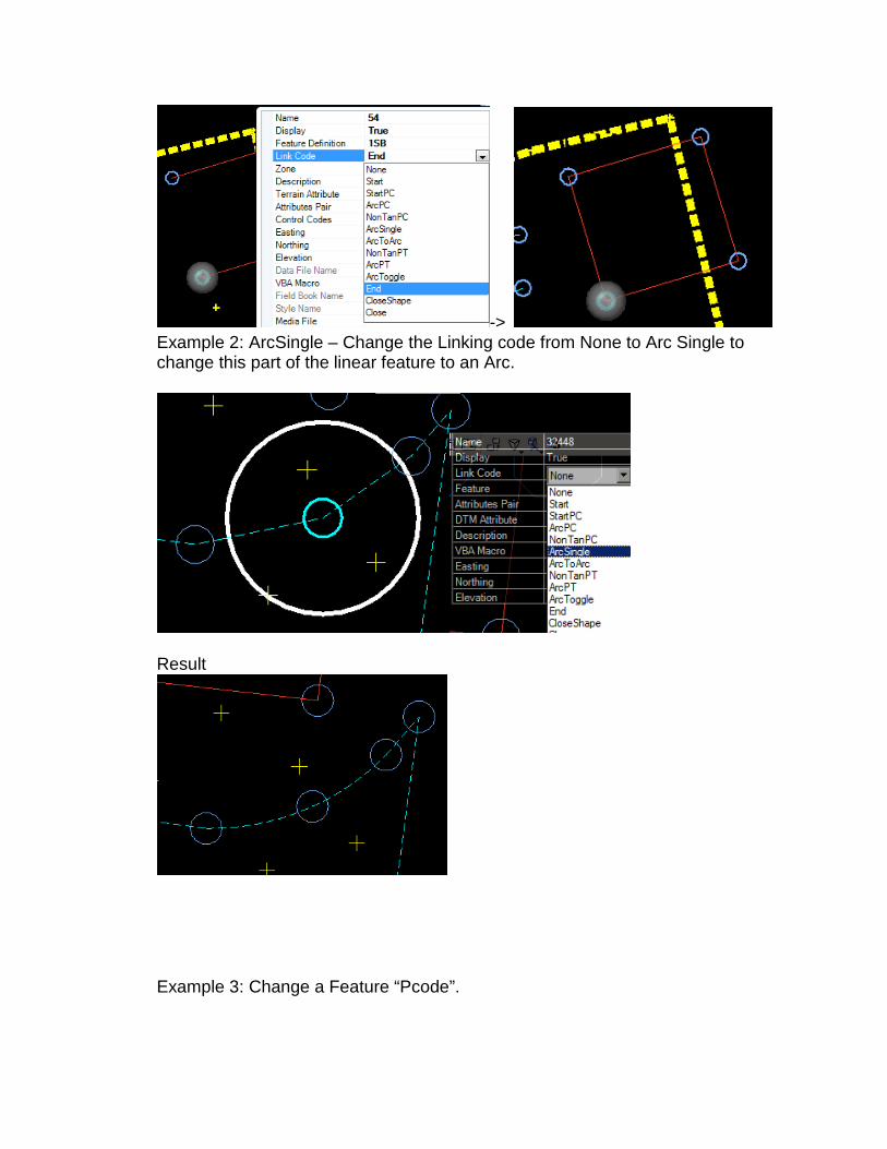
-> Example 2: ArcSingle – Change the Linking code from None to Arc Single to change this part of the linear feature to an Arc.
Result
Example 3: Change a Feature “Pcode”.

-> Example 4: Include Point as Spot in DTM. (Note, Displaying triangles is discussed later in the chapter but changing a Point DTM attribute is shown below:
Example 5: Editing the elevation of a group of points in the Details Panel.
Linear Feature Editing

EXAMPLE 1 – Add Point to Chain: In this example, I am going to add the point in the lower left to be included in this shed. Step 1: Choose the command from the context menu.
. Step 2: Choose the point you want to add & when prompted, Accept the solution.
Step 3: Point added.
Step 4: Change the Linkng Code to close.
Example 2 – JOIN 2 Chains

Step 1: Choose the command.
Step 2 You will be prompted to choose the element you want to join this chain to. Results are shown below.
Note: Linear elements need to move in the same direction so you may have to use the Transpose tool to reverse direction of one linear feature prior to joining to another linear feature.
Example 3 – Delete a Chain. Note: Convert to Linear Elements prior to deleting. This process leaves the points in the dataset.

Crossing Breaklines
Tag the Message Center Tab on the Details dialog and then tag a line to locate crossing breaklines which you can then edit as described above.
Exporting to COGO Since Point & Linear Features are stored in the DGN and you can edit this data as discussed above, there is no reason to write all these to a GPK. At this time though, you may want to export specific points or linear features to the GPK to be used to Store Parcels, to be used with the Best Fit Alignment tool, etc.
1) Export the whole fieldbook:
2) Display/Exporting points, Survey Chains, or Category of points Probably the easiest way to Display/Export a Survey Chain, a group of points, or a Category (i.e. All Property related shots) is to turn off Display of the Field Book and enter the Feature Styles Tree and check the appropriate item(s) as shown in the example below

which is exporting all Property, CL, & ROW related points. Step 1: Go to Civil Standards & turn on the groups of points you wish to export.
Step 2: Go back to the Survey tab and Right click the Field Book to choose the Export ooption.

Terrain Models
Overview:
With the implementation of SS3, Microstation created a new element type called Terrain Model. The steps below show how to display triangles and contours, how to export the Terrain Model to a GeoPak TIN file (this will not be necessary in the future but should be done until the external TIN file is phased out), creating Surfaces from 3d Graphics, and merging TIN’s. Triangles, Contours, etc. are just a display aspect of the Terrain which is created from Survey based on whether a Pcode is set to be included in the trianglulation. PCODES included in a TIN:
Rural Drainage *DITCH *PDCH *WW * HDW
Creation, Display, & Settings
As mentioned in the Overview area above, the Terrain Model is generated automatically when survey points are processed. Dissolve Option, Side Length of triangles, Symbology, Contours Major/Minor intervals are all set by default but can be changed by going to properties of the Terrain Model or using Microstation’s Element ID. Settings are discussed below.
1) LARGE NUMBER OF POINTS: If you have a large number of points, you may see some

slowness when editing features because of the automatic triangulation adjustment. You may want to delete the surface (Shown in 1st image below) and then come back and create a Terrain Model from field books (image right below) when editing is complete.
2) Display Step 1
Step 2 – The example below turns off Triangle Display
You can see from the dialog above, you can display Contours, Flow arrows, etc., adjust the triangle length, and actually name the Terrain. Remember another option is to choose the TIN & use Element ID to change this info.

3) Exporting to a TIN Triangles can be exported to a GeoPak TIN by using the context menu as shown below.
4) To create a surface from 3D graphic elements (i.e. Photo/Lidar):
(Everything below needs to be re-written.)
All Field Books are combined into one surface with a default name of “All Field Books” but there are times when you need to include/create a TIN from graphics such as Lidar & Photo surveys. The steps below show how to create a Surface from 3d Elements (in this example, a photo survey.)
a. Reference in the 3d DGN containing the 3d elements. b. Create an empty surface by right-clicking the Surface branch in the Data Tree then
choosing Create Surface from the menu and Empty Surface from the submenu to create a Surface 2 as shown below.

->
c. Rename the Surface in the Details Pane if you wish and also set the Side Length option in the Data Acquisition Details dialog.
d. Use MicroStation's Element Selection functionality to select every instance of a particular graphic feature (spot or breakline or void etc.).
e. In the Data Tree, expand the Features branch and right-click on the Surface Feature corresponding to the selected DGN 3D graphical data. For example, if you selected breaklines in the workspace, you would then right-click on Breaklines in the Data Tree. In the image above, the selected items were breaklines, so the right-click and import were performed on the Breaklines branch.
f. On the pop-up, click Import Selection.

g. Repeat the select and import process for all other Surface feature types you wish to import from the graphical data: Spots, Triangles, Holes, Boundaries, etc. Each type of feature must be imported separately.
Note: This 3d graphics can be in the DGN containing the field survey or another 3D DGN referenced to this file.
5) Merging/Appending Surfaces
Both the Merge and Append functions combine two surfaces into a single surface; the difference is that Merge is a destructive operation while Append is not.
Example: You might combine an aerial survey with field survey data or a LIDAR surface with field survey data.
Example: Merge Surface 1 into Surface 2
When Surface 1 is merged, all the data in Surface 2 underneath the boundary of surface 1 is destroyed and then Surface 1 is used to fill the destructed area.
Example: Append Surface 1 into Surface 2.
When Surface 1 is appended, Surface 2 remains 100% intact. The data contained in surface 1 is intermingled with the information contained in Surface 2.
Two Methods to Create a Merged/Appended Surface:
1. Merge/Append surfaces already contained in the DGN file 2. Merge/Append external surfaces
Merge/Append Internal Surfaces
Create a new, empty surface to contain the merged/appended data:

->
Right-click on the new surface and choose Append From.
Select the base surface. This is usually the largest surface or the one that acts as lowest level of information to be superseded or augmented by more detailed information.
Right-click again to merge or append additional surfaces.

Now, You’ll have 3 surfaces to display with the All-Merged being a combination of the Field Books & the Photo (3d Graphics) data.
Merge/Append External Surfaces
The process is identical to the internal surface process except that, instead of using surfaces already stored in the DGN, you must select external files with formats supported by Data Acquisition. The external surface can be any of the supported surface type. The external surface is either appended to or merged with the existing surface.
One Internal Surface\One External Surface
Right-click on the surface to which you wish to add surface data.
Choose Append External Surface or Merge External Surface from the menu.
Navigate to the desired file and double-click it.
Import Two External Surfaces, Append, then Merge
Import the surfaces you wish to merge (see Importing Surfaces).
Create an empty surface (see Creating an Empty Surface).
Right-click on the newly created empty surface then choose Append From and select the first of the imported surfaces.
Right-click on the newly created empty surface then choose Merge From and select the second of the imported surfaces.

Right-click again on the previously empty surface then choose Merge From and select the second of the imported surfaces.
Merge Two External Surfaces
Import the first surface you wish to merge (see Importing Surfaces).
Right-click on the newly imported surface and choose Merge External Surface from the menu.
Navigate to the desired surface file then double-click it.
Changing Merge/Append Order
Surfaces are processed from the top of the surface list to the bottom. Each surface in the surface list is merged/appended to the result of the merge/append operations performed on the items above, thus there may be occasions where the order of surface merging needs to be adjusted. To do so:
Right-click on the surface name in the Data Tree and choose Rearrange Surfaces from the menu.
On the Composite Surface dialog:
Select a surface and click the Up arrow to raise the selected surface's position in the surface list.
Select a surface and click the Down arrow to lower that surface's position in the surface list.
Select a surface and click Delete to eliminate the surface.
Expand the drop-down and choose whether you wish the surfaces to be Appended or Merged.
Adding graphical elements You do have the ability to add graphical elements to DA.

1. Copying linear elements - An example is that the Survey crew picks up Face of
Curb only & you need to generate the Top of Curb (Copy 6” over & 6” up). You can just use Microstation’s Copy Parallel in a Top View and copy it 6” and then use Microstation’s Move command with a dx=0,0,0.5 keyin to move it up 6”. The linear element is included in the TIN automatically
2. Elements drawn in 3d can be added to a Field Book as graphical elements by right clicking a field book and Loading Features from current Graphics.
This feature examines all graphical data in the current DGN model and compares the symbolgy against the currently loaded style file. Where the graphical data symbology matches a style file feature, the graphical data is converted to Data Acquisition Point and Linear features. If a style is not matched, it’s just added as a linear feature which can be edited to be included as a spot, breakline, etc. in the TIN.
Implementing with existing projects processed with GeoPak Survey
You can import visualized graphics as mentioned in the #2 item in the section above but this does not maintain point numbers & survey chain names.
To maintain GeoPak Survey processed point numbers & chain names, you would:
Go through GeoPak Survey, open a dataset, then tag Update OBS & XYZ, and then Process Update or Create New which updates/creates new .OBS & .XYZ files.
Drag & Drop the XYZ files into DA choosing XYZ CTL Type as the data format (if prompted).