Embed Size (px)
Citation preview

Page 1
About LinxFrom all of us here at Linx Technologies, thank you for your interestin learning more about our rapidly growing company. The followingsection will provide a brief insight into our history, vision, and future.
Our HistoryFounded in 1996, Linx Technologies is a privately-held growth-mode corporation consisting of three divisions. The first andprimary division, Linx Technologies, shares the corporate nameand specializes in low-cost wireless modules and OEM RF productsolutions. The second division, Antenna Factor, specializes in cost-effective standard and custom antennas for consumer andindustrial wireless products. Finally, a third division, Connector City,provides world-class standard and custom connectors and cableassemblies for high-volume OEM applications.
Our VisionRadio Frequency (RF) is a complex science requiring a uniquegrasp of both advanced technical issues and complex legalrequirements; thus, adding wireless capabilities to a product hastraditionally been a costly and time-consuming proposition. Thishas limited the widespread use of RF and prevented manypotentially useful products from reaching production. Here at Linx, we believe that every engineer, regardless of trainingand experience, should have the option of using RF technology.That’s why “Wireless Made Simple” is more than just a motto, it’sour commitment. A commitment to offering the highest quality RFproducts designed to provide a simple and cost-effective path tomaking any product wireless.Through its three divisions, Linx Technologies, Inc. is positioned totake advantage of the exploding wireless market it helped to create.We believe that our vision for enabling engineers of all skill levelsin diverse industries to harness the power of RF will allow Linxcontinued recognition as a leader in RF solutions.
Welcome to the Products & Services of
WIRELESS MADE SIMPLE ®
Phone: (541) 471-6256Fax: (541) [email protected]
Page 3Page 2
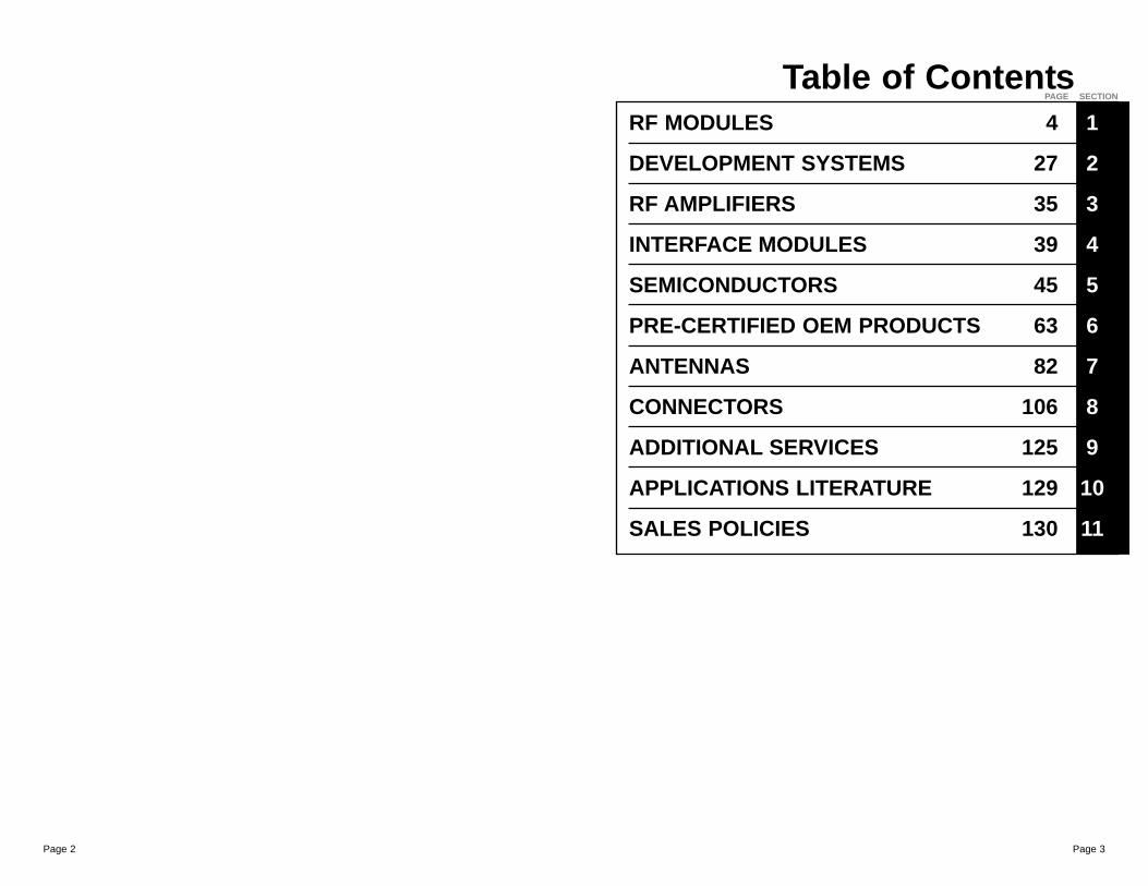
RF MODULES 4 1
DEVELOPMENT SYSTEMS 27 2
RF AMPLIFIERS 35 3
INTERFACE MODULES 39 4
SEMICONDUCTORS 45 5
PRE-CERTIFIED OEM PRODUCTS 63 6
ANTENNAS 82 7
CONNECTORS 106 8
ADDITIONAL SERVICES 125 9
APPLICATIONS LITERATURE 129 10
SALES POLICIES 130 11
Table of ContentsPAGE SECTION
Page 5Page 4
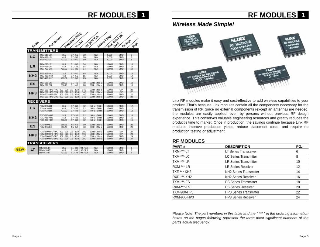
Linx RF modules make it easy and cost-effective to add wireless capabilities to yourproduct. That’s because Linx modules contain all the components necessary for thetransmission of RF. Since no external components (except an antenna) are needed,the modules are easily applied, even by persons without previous RF designexperience. This conserves valuable engineering resources and greatly reduces theproduct’s time to market. Once in production, the savings continue because Linx RFmodules improve production yields, reduce placement costs, and require noproduction testing or adjustment.
RF MODULES 1
RF MODULESPART # DESCRIPTION PG.TRM-***-LT LT Series Transceiver 6TXM-***-LC LC Series Transmitter 8TXM-***-LR LR Series Transmitter 10RXM-***-LR LR Series Receiver 12TXE-***-KH2 KH2 Series Transmitter 14RXD-***-KH2 KH2 Series Receiver 16TXM-***-ES ES Series Transmitter 18RXM-***-ES ES Series Receiver 20TXM-900-HP3 HP3 Series Transmitter 22RXM-900-HP3 HP3 Series Receiver 24
Wireless Made Simple!
Part Number
Series
Frequency
(MHz)
Vcc (V)
Icc (m
A) Typ.
Analog Range
Max. Data
Rate
(bps)Pack
age
Page
LC
KH2
RF MODULES 1
HP3
ES
ES
HP3
LR
Please Note: The part numbers in this table and the “ *** ” in the ordering informationboxes on the pages following represent the three most significant numbers of thepart’s actual frequency.
TRANSMITTERS
RECEIVERS
KH2
NEW
LR
TXM-315-LC 315 2.7 - 5.2 3.0 N/A 5,000 SMD 8TXM-418-LC 418 2.7 - 5.2 3.0 N/A 5,000 SMD 8TXM-433-LC 433.92 2.7 - 5.2 3.0 N/A 5,000 SMD 8
TXM-315-LR 315 2.1 - 3.6 3.4 N/A 10,000 SMD 10TXM-418-LR 418 2.1 - 3.6 3.4 N/A 10,000 SMD 10TXM-433-LR 433.92 2.1 - 3.6 3.4 N/A 10,000 SMD 10
TXE-315-KH2 315 2.7 - 5.2 1.5 N/A 5,000 SMD 14TXE-418-KH2 418 2.7 - 5.2 1.5 N/A 5,000 SMD 14TXE-433-KH2 433.92 2.7 - 5.2 1.5 N/A 5,000 SMD 14
TXM-869-ES 869.85 2.1 - 4.0 7.0 20Hz - 28kHz 56,000 SMD 18TXM-916-ES 916.48 2.1 - 4.0 7.0 20Hz - 28kHz 56,000 SMD 18
TXM-900-HP3-PPO 902 - 928 2.8 - 13.0 14.0 50Hz - 28kHz 56,000 SIP 22TXM-900-HP3-PPS 902 - 928 2.8 - 13.0 14.0 50Hz - 28kHz 56,000 SIP 22TXM-900-HP3-SPO 902 - 928 2.8 - 13.0 14.0 50Hz - 28kHz 56,000 SMD 22TXM-900-HP3-SPS 902 - 928 2.8 - 13.0 14.0 50Hz - 28kHz 56,000 SMD 22
RXM-315-LR 315 2.7 - 3.6 5.2 50Hz - 5kHz 10,000 SMD 12RXM-418-LR 418 2.7 - 3.6 5.2 50Hz - 5kHz 10,000 SMD 12RXM-433-LR 433.92 2.7 - 3.6 5.2 50Hz - 5kHz 10,000 SMD 12
RXD-315-KH2 315 2.7 - 3.6 5.2 50Hz - 5kHz 10,000 SMD 16RXD-418-KH2 418 2.7 - 3.6 5.2 50Hz - 5kHz 10,000 SMD 16RXD-433-KH2 433.92 2.7 - 3.6 5.2 50Hz - 5kHz 10,000 SMD 16
RXM-869-ES 869.85 4.5 - 5.5 6.0 20Hz - 28kHz 56,000 SMD 20RXM-916-ES 916.48 4.5 - 5.5 6.0 20Hz - 28kHz 56,000 SMD 20
RXM-900-HP3-PPO 902 - 928 2.8 - 13.0 19.0 50Hz - 28kHz 56,000 SIP 24RXM-900-HP3-PPS 902 - 928 2.8 - 13.0 19.0 50Hz - 28kHz 56,000 SIP 24RXM-900-HP3-SPO 902 - 928 2.8 - 13.0 19.0 50Hz - 28kHz 56,000 SMD 24RXM-900-HP3-SPS 902 - 928 2.8 - 13.0 19.0 50Hz - 28kHz 56,000 SMD 24
TRM-315-LT 315 2.1 - 3.6 9.5 / 7.9 N/A 10,000 SMD 6TRM-418-LT 418 2.1 - 3.6 9.5 / 7.9 N/A 10,000 SMD 6TRM-433-LT 433.92 2.1 - 3.6 9.5 / 7.9 N/A 10,000 SMD 6
TRANSCEIVERS
LT
Page 7Page 6
WIRELESS MADE SIMPLE ®
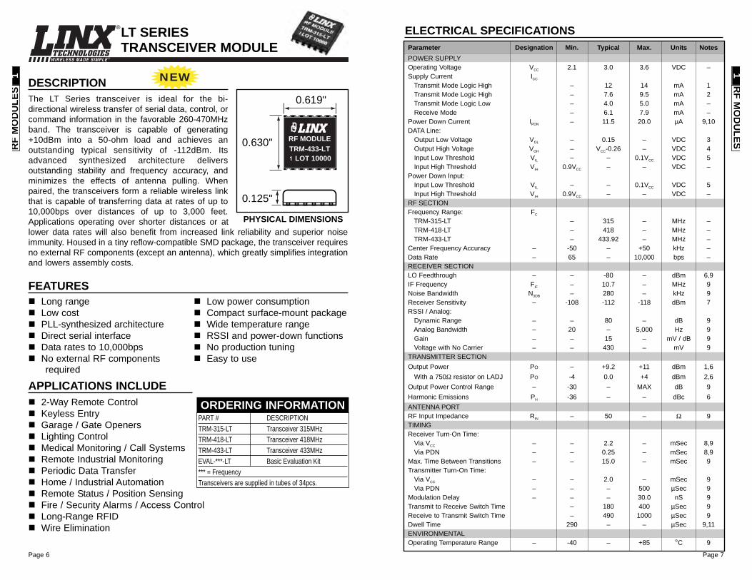
DESCRIPTIONThe LT Series transceiver is ideal for the bi-directional wireless transfer of serial data, control, orcommand information in the favorable 260-470MHzband. The transceiver is capable of generating+10dBm into a 50-ohm load and achieves anoutstanding typical sensitivity of -112dBm. Itsadvanced synthesized architecture deliversoutstanding stability and frequency accuracy, andminimizes the effects of antenna pulling. Whenpaired, the transceivers form a reliable wireless linkthat is capable of transferring data at rates of up to10,000bps over distances of up to 3,000 feet.Applications operating over shorter distances or atlower data rates will also benefit from increased link reliability and superior noiseimmunity. Housed in a tiny reflow-compatible SMD package, the transceiver requiresno external RF components (except an antenna), which greatly simplifies integrationand lowers assembly costs.
0.125"
0.630"
0.619"
LOT 10000TRM-433-LTRF MODULE
2-Way Remote Control Keyless EntryGarage / Gate OpenersLighting ControlMedical Monitoring / Call SystemsRemote Industrial MonitoringPeriodic Data TransferHome / Industrial AutomationRemote Status / Position SensingFire / Security Alarms / Access ControlLong-Range RFIDWire Elimination
APPLICATIONS INCLUDE
Long rangeLow cost PLL-synthesized architectureDirect serial interfaceData rates to 10,000bpsNo external RF componentsrequired
Low power consumptionCompact surface-mount packageWide temperature rangeRSSI and power-down functionsNo production tuningEasy to use
FEATURES
PART # DESCRIPTIONTRM-315-LT Transceiver 315MHzTRM-418-LT Transceiver 418MHz TRM-433-LT Transceiver 433MHzEVAL-***-LT Basic Evaluation Kit*** = FrequencyTransceivers are supplied in tubes of 34pcs.
ORDERING INFORMATION
LT SERIES TRANSCEIVER MODULE
PHYSICAL DIMENSIONS
ELECTRICAL SPECIFICATIONSParameter Designation Min. Typical Max. Units NotesPOWER SUPPLYOperating Voltage VCC 2.1 3.0 3.6 VDC –Supply Current ICC
Transmit Mode Logic High – 12 14 mA 1Transmit Mode Logic High – 7.6 9.5 mA 2Transmit Mode Logic Low – 4.0 5.0 mA –Receive Mode – 6.1 7.9 mA –
Power Down Current IPDN – 11.5 20.0 µA 9,10DATA Line:
Output Low Voltage VOL – 0.15 – VDC 3Output High Voltage VOH – VCC-0.26 – VDC 4Input Low Threshold VIL – – 0.1VCC VDC 5Input High Threshold VIH 0.9VCC – – VDC –
Power Down Input:Input Low Threshold VIL – – 0.1VCC VDC 5Input High Threshold VIH 0.9VCC – – VDC –
RF SECTIONFrequency Range: FC
TRM-315-LT – 315 – MHz –TRM-418-LT – 418 – MHz –TRM-433-LT – 433.92 – MHz –
Center Frequency Accuracy – -50 – +50 kHz –Data Rate – 65 – 10,000 bps –RECEIVER SECTIONLO Feedthrough – – -80 – dBm 6,9IF Frequency FIF – 10.7 – MHz 9Noise Bandwidth N3DB – 280 – kHz 9Receiver Sensitivity – -108 -112 -118 dBm 7RSSI / Analog:
Dynamic Range – – 80 – dB 9Analog Bandwidth – 20 – 5,000 Hz 9Gain – – 15 – mV / dB 9Voltage with No Carrier – – 430 – mV 9
TRANSMITTER SECTIONOutput Power PO – +9.2 +11 dBm 1,6
With a 750Ω resistor on LADJ PO -4 0.0 +4 dBm 2,6Output Power Control Range – -30 – MAX dB 9Harmonic Emissions PH -36 – – dBc 6ANTENNA PORTRF Input Impedance RIN – 50 – Ω 9TIMINGReceiver Turn-On Time:
Via VCC – – 2.2 – mSec 8,9Via PDN – – 0.25 – mSec 8,9
Max. Time Between Transitions – – 15.0 – mSec 9Transmitter Turn-On Time:
Via VCC – – 2.0 – mSec 9Via PDN – – – 500 µSec 9
Modulation Delay – – – 30.0 nS 9Transmit to Receive Switch Time – 180 400 µSec 9Receive to Transmit Switch Time – 490 1000 µSec 9Dwell Time 290 – – µSec 9,11ENVIRONMENTALOperating Temperature Range – -40 – +85 °C 9
RF
MO
DU
LES
1R
F MO
DU
LES1
NEW
Page 8
WIRELESS MADE SIMPLE ®
Page 9
ELECTRICAL SPECIFICATIONS
ABSOLUTE MAXIMUM RATINGS
Supply Voltage VCC -0.3 to +6.0 VDCAny Input or Output Pin -0.3 to Vcc VDCOperating Temperature -30 to +70 °CStorage Temperature -45 to +85 °CSoldering Temperature +225°C for 10 seconds
*NOTE* Exceeding any of the limits of this section may lead to permanentdamage to the device. Furthermore, extended operation at these maximumratings may reduce the life of this device.
1. Current draw with DATA pin held continuously high.2. Current draw with DATA pin low.3. RF out connected to a 50Ω load.4. LADJ through 430Ω resistor.5. Characterized, but not tested.
Notes
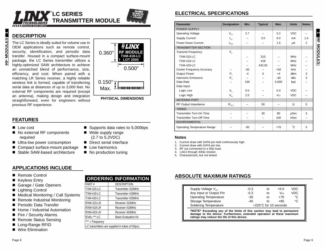
Parameter Designation Min. Typical Max. Units NotesPOWER SUPPLYOperating Voltage VCC 2.7 – 5.2 VDC –Supply Current ICC – 3.0 6.0 mA 1,4Power-Down Current IPDN – – 1.5 µA 2TRANSMITTER SECTIONTransmit Frequency: FC
TXM-315-LC – 315 – MHz –TXM-418-LC – 418 – MHz –TXM-433-LC – 433.92 – MHz –
Center Frequency Accuracy – -50 – +50 kHz –Output Power Po -4 0 +4 dBm 3Harmonic Emissions PH – – -40 dBc 3Data Rate – 100 – 5,000 bps –Data Input:
Logic Low VIL 0.0 – 0.4 VDC –Logic High VIH 2.5 – Vcc VDC –
ANTENNA PORTRF Output Impedance ROUT – 50 – Ω 5TIMINGTransmitter Turn-On Time – – 30 80 µSec 3Transmitter Turn-Off Time – – – 100 nSec –ENVIRONMENTAL
Operating Temperature Range – -30 – +70 °C 5
RF M
OD
ULES
1
DESCRIPTIONThe LC Series is ideally suited for volume use inOEM applications such as remote control,security, identification, and periodic datatransfer. Housed in a compact surface-mountpackage, the LC Series transmitter utilizes ahighly-optimized SAW architecture to achievean unmatched blend of performance, size,efficiency, and cost. When paired with amatching LR Series receiver, a highly reliablewireless link is formed, capable of transferringserial data at distances of up to 3,000 feet. Noexternal RF components are required (exceptan antenna), making design and integrationstraightforward, even for engineers withoutprevious RF experience.
LC SERIES TRANSMITTER MODULE
0.360"
0.500"
0.150"Max.
TXM-418-LCRF MODULE
LOT 2000
Remote ControlKeyless EntryGarage / Gate OpenersLighting ControlMedical Monitoring / Call SystemsRemote Industrial MonitoringPeriodic Data TransferHome / Industrial AutomationFire / Security AlarmsRemote Status SensingLong-Range RFIDWire Elimination
APPLICATIONS INCLUDE
Low costNo external RF componentsrequired
Ultra-low power consumptionCompact surface-mount packageStable SAW-based architecture
Supports data rates to 5,000bpsWide supply range (2.7 to 5.2VDC)
Direct serial interfaceLow harmonicsNo production tuning
FEATURES
PART # DESCRIPTIONTXM-315-LC Transmitter 315MHzTXM-418-LC Transmitter 418MHz TXM-433-LC Transmitter 433MHzRXM-315-LR Receiver 315MHzRXM-418-LR Receiver 418MHzRXM-433-LR Receiver 433MHzEVAL-***-LC Basic Evaluation Kit*** = FrequencyLC transmitters are supplied in tubes of 50pcs.
ORDERING INFORMATION
PHYSICAL DIMENSIONS
RF
MO
DU
LES
1
Page 10
WIRELESS MADE SIMPLE ®
Page 11Page 11
ABSOLUTE MAXIMUM RATINGS
Supply Voltage VCC -0.3 to +3.6 VDCAny Input or Output Pin -0.3 to VCC + 0.3 VDCOperating Temperature -40 to +85 °CStorage Temperature -40 to +90 °CSoldering Temperature +225°C for 10 seconds
*NOTE* Exceeding any of the limits of this section may lead to permanentdamage to the device. Furthermore, extended operation at these maximumratings may reduce the life of this device.
1. With a 50% duty cycle.2. With a 750Ω resistor on LADJ.3. See graph on Page 3 of the LR Series Transmitter Data Guide.4. Characterized, but not tested.
Notes
ELECTRICAL SPECIFICATIONS
Parameter Designation Min. Typical Max. Units Notes
POWER SUPPLYOperating Voltage VCC 2.1 3.0 3.6 VDC –Supply Current: ICC – 3.4 – mA 1,2
Logic High – 5.1 – mA 2Logic Low – 1.8 – mA –
Power-Down Current IPDN – 5.0 – nA –TRANSMITTER SECTIONTransmit Frequency: FC
TXM-315-LR – 315 – MHz –TXM-418-LR – 418 – MHz –TXM-433-LR – 433.92 – MHz –
Center Frequency Accuracy – -50 – +50 kHz –Output Power PO -4 0 +4 dBm 2Output Power Control Range – -80 – +10 dB 3Harmonic Emissions PH -40 – – dBc –Data Rate – DC – 10,000 bps –Data Input:
Logic Low – – – 0.25 VDC –Logic High – VCC-0.25 – – VDC –
Power-Down Input:Logic Low – – – 0.25 VDC –Logic High – VCC-0.25 – – VDC –
ANTENNA PORTRF Output Impedance ROUT – 50 – Ω 4TIMINGTransmitter Turn-On Time:
Via VCC or PDN – – 1.0 – mSec 4Modulation Delay – – – 30 nS 4
ENVIRONMENTAL
Operating Temperature Range – -40 – +85 °C 4
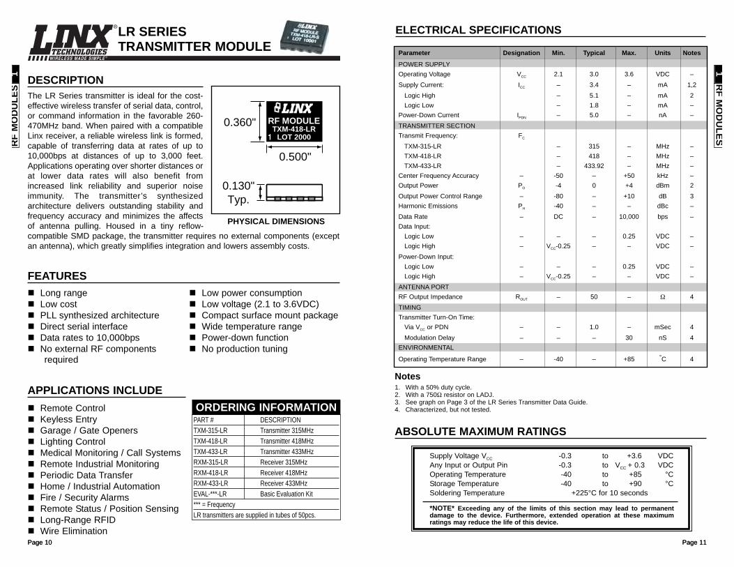
DESCRIPTIONThe LR Series transmitter is ideal for the cost-effective wireless transfer of serial data, control,or command information in the favorable 260-470MHz band. When paired with a compatibleLinx receiver, a reliable wireless link is formed,capable of transferring data at rates of up to10,000bps at distances of up to 3,000 feet.Applications operating over shorter distances orat lower data rates will also benefit fromincreased link reliability and superior noiseimmunity. The transmitter’s synthesizedarchitecture delivers outstanding stability andfrequency accuracy and minimizes the affectsof antenna pulling. Housed in a tiny reflow-compatible SMD package, the transmitter requires no external components (exceptan antenna), which greatly simplifies integration and lowers assembly costs.
Page 10
LR SERIES TRANSMITTER MODULE
0.360"
0.500"
0.130"Typ.
TXM-418-LRRF MODULE
LOT 2000
Remote Control Keyless EntryGarage / Gate OpenersLighting ControlMedical Monitoring / Call SystemsRemote Industrial MonitoringPeriodic Data TransferHome / Industrial AutomationFire / Security AlarmsRemote Status / Position SensingLong-Range RFIDWire Elimination
APPLICATIONS INCLUDE
Long rangeLow cost PLL synthesized architectureDirect serial interfaceData rates to 10,000bps No external RF componentsrequired
Low power consumptionLow voltage (2.1 to 3.6VDC) Compact surface mount packageWide temperature rangePower-down functionNo production tuning
FEATURES
PART # DESCRIPTIONTXM-315-LR Transmitter 315MHzTXM-418-LR Transmitter 418MHz TXM-433-LR Transmitter 433MHzRXM-315-LR Receiver 315MHzRXM-418-LR Receiver 418MHzRXM-433-LR Receiver 433MHzEVAL-***-LR Basic Evaluation Kit*** = FrequencyLR transmitters are supplied in tubes of 50pcs.
ORDERING INFORMATION
PHYSICAL DIMENSIONS
RF M
OD
ULES
1R
F M
OD
ULE
S1
Page 12 Page 13
WIRELESS MADE SIMPLE ®
ELECTRICAL SPECIFICATIONS
1. The LR can utilize a 4.3 to 5.2VDC supply provided a 330-ohm resistor is placed in series with VCC.2. Into a 50-ohm load.3. When operating from a 5V source, it is important to consider that the output will swing to well less than
5 volts as a result of the required dropping resistor. Please verify that the minimum voltage will meet thehigh threshold requirement of the device to which data is being sent.
4. For BER of 10-5 at 1,200bps.5. Characterized, but not tested.6. Time to valid data output.
Notes
Parameter Designation Min. Typical Max. Units NotesPOWER SUPPLYOperating Voltage VCC 2.7 3.0 3.6 VDC –
With Dropping Resistor 4.3 5.0 5.2 VDC 1,5Supply Current ICC 4.0 5.2 7.0 mA –Power-Down Current IPDN 20.0 28.0 35.0 µA 5RECEIVER SECTIONReceive Frequency: FC
RXM-315-LR – 315 – MHz –RXM-418-LR – 418 – MHz –RXM-433-LR – 433.92 – MHz –
Center Frequency Accuracy – -50 – +50 kHz –LO Feedthrough – – -80 – dBm 2,5IF Frequency – – 10.7 – MHz 5Noise Bandwidth N3dB – 280 – kHz –Data Rate – 100 – 10,000 bps –Data Output:
Logic Low – 0.0 – 0.4 VDC 3Logic High – VCC-0.4 – VCC VDC 3
Receiver Sensitivity – -106 -112 -118 dBm 4RSSI / Analog:
Dynamic Range – – 80 – dB 5Analog Bandwidth – 50 – 5,000 Hz 5Gain – – 16.0 – mV/dB 5Voltage With No Carrier – – 1.5 – V 5
ANTENNA PORTRF Input Impedance RIN – 50 – Ω 5TIMINGReceiver Turn-On Time:
Via VCC – 3.0 7.0 10.0 mSec 5,6Via PDN – 0.04 0.25 0.5 mSec 5,6
Max. Time Between Transitions – – 10.0 – mSec 5ENVIRONMENTALOperating Temperature Range – -40 – +70 °C 5
ABSOLUTE MAXIMUM RATINGS
Supply Voltage VCC -0.3 to +3.6 VDCSupply Voltage VCC Using Resistor -0.3 to +5.2 VDCAny Input or Output Pin -0.3 to +3.6 VDCRF Input 0 dBmOperating Temperature -40 to +70 °CStorage Temperature -45 to +85 °CSoldering Temperature +225°C for 10 seconds
*NOTE* Exceeding any of the limits of this section may lead to permanentdamage to the device. Furthermore, extended operation at these maximumratings may reduce the life of this device.
LR SERIES RECEIVER MODULE
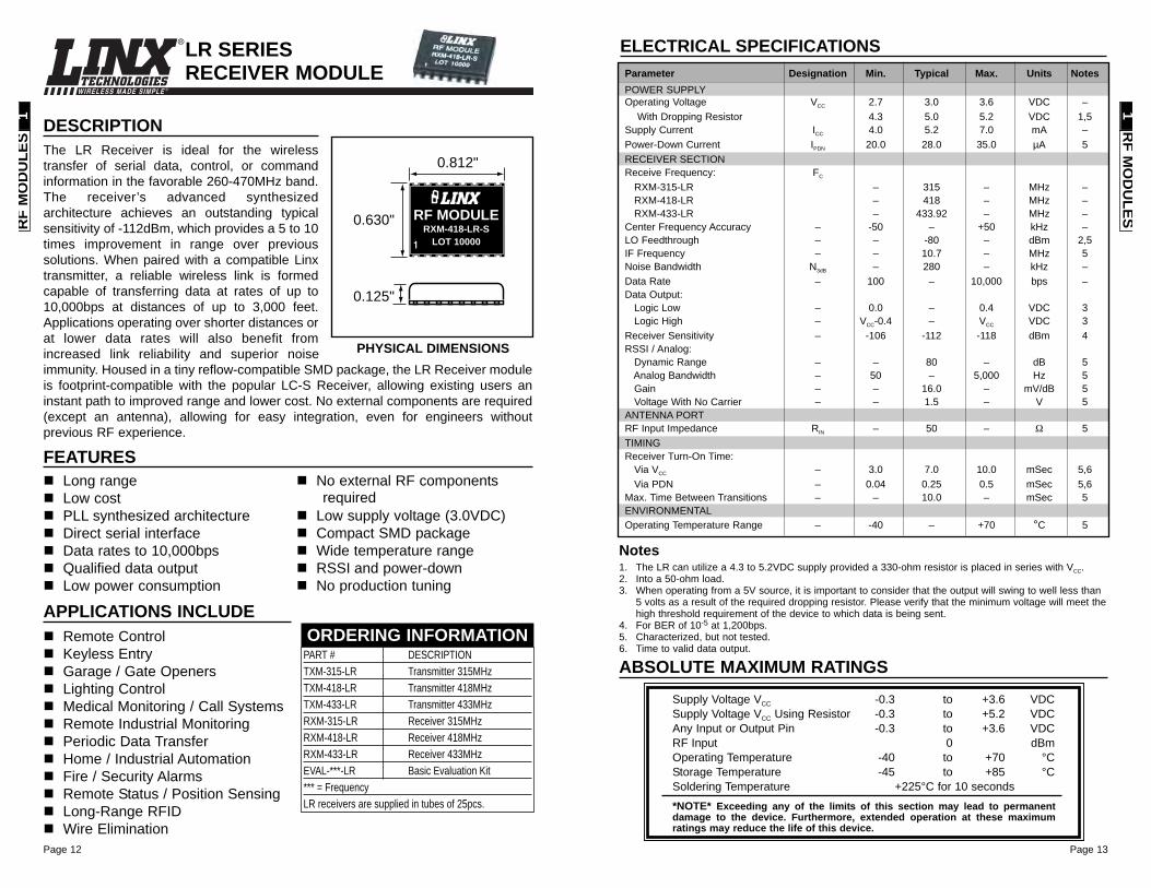
DESCRIPTIONThe LR Receiver is ideal for the wirelesstransfer of serial data, control, or commandinformation in the favorable 260-470MHz band.The receiver’s advanced synthesizedarchitecture achieves an outstanding typicalsensitivity of -112dBm, which provides a 5 to 10times improvement in range over previoussolutions. When paired with a compatible Linxtransmitter, a reliable wireless link is formedcapable of transferring data at rates of up to10,000bps at distances of up to 3,000 feet.Applications operating over shorter distances orat lower data rates will also benefit fromincreased link reliability and superior noiseimmunity. Housed in a tiny reflow-compatible SMD package, the LR Receiver moduleis footprint-compatible with the popular LC-S Receiver, allowing existing users aninstant path to improved range and lower cost. No external components are required(except an antenna), allowing for easy integration, even for engineers withoutprevious RF experience.
0.125"
0.630"LOT 10000
RXM-418-LR-SRF MODULE
0.812"
Remote Control Keyless EntryGarage / Gate OpenersLighting ControlMedical Monitoring / Call SystemsRemote Industrial MonitoringPeriodic Data TransferHome / Industrial AutomationFire / Security AlarmsRemote Status / Position SensingLong-Range RFIDWire Elimination
APPLICATIONS INCLUDE
Long rangeLow cost PLL synthesized architectureDirect serial interfaceData rates to 10,000bpsQualified data outputLow power consumption
No external RF componentsrequired
Low supply voltage (3.0VDC) Compact SMD packageWide temperature rangeRSSI and power-downNo production tuning
FEATURES
PART # DESCRIPTIONTXM-315-LR Transmitter 315MHzTXM-418-LR Transmitter 418MHz TXM-433-LR Transmitter 433MHzRXM-315-LR Receiver 315MHzRXM-418-LR Receiver 418MHzRXM-433-LR Receiver 433MHzEVAL-***-LR Basic Evaluation Kit*** = FrequencyLR receivers are supplied in tubes of 25pcs.
ORDERING INFORMATION
PHYSICAL DIMENSIONS
RF M
OD
ULES
1R
F M
OD
ULE
S1
Page 14 Page 15
WIRELESS MADE SIMPLE ®
ELECTRICAL SPECIFICATIONS
1. Current draw with 50% mark / space ratio.2. Into a 50Ω load.3. With 430Ω resistor on LADJ.4. Characterized, but not tested.
Notes
Parameter Designation Min. Typical Max. Units Notes
POWER SUPPLYOperating Voltage VCC 2.7 – 5.2 VDC –Supply Current ICC – 1.5 – mA 1,4Power-Down Current IPDN – 1.0 – µA –TRANSMITTER SECTIONTransmit Frequency: FC
TXE-315-KH2 – 315 – MHz –TXE-418-KH2 – 418 – MHz –TXE-433-KH2 – 433.92 – MHz –
Center Frequency Accuracy – -75 – +75 kHz –Output Power PO -4 +2 +4 dBm 2,3Harmonic Emissions: PH
TXE-315-KH2 -40 – – dBc –TXE-418-KH2 -40 – – dBc –TXE-433-KH2 -45 – – dBc –
ANTENNA PORTRF Output Impedance ROUT – 50 – Ω 4ENCODERData Length – – 26 bits 3x – – –Average Data Duty Cycle – – 50% – – 4Encoder Oscillator FENC – 70 – kHz 4Data Input:
Logic Low VIL 0 – 0.2 x VCC VDC 4Logic High VIH VCC x 0.8 – VCC VDC 4
Input Sink Current – 0.6 1.0 1.2 mA 4ENVIRONMENTALOperating Temperature Range – -30 – +70 °C 4
ABSOLUTE MAXIMUM RATINGS
Supply Voltage VCC -0.3 to +6.0 VDCAny Input or Output Pin -0.3 to VCC VDCOperating Temperature -30 to +70 °CStorage Temperature -45 to +85 °CSoldering Temperature +225°C for 10 seconds
*NOTE* Exceeding any of the limits of this section may lead to permanentdamage to the device. Furthermore, extended operation at these maximumratings may reduce the life of this device.
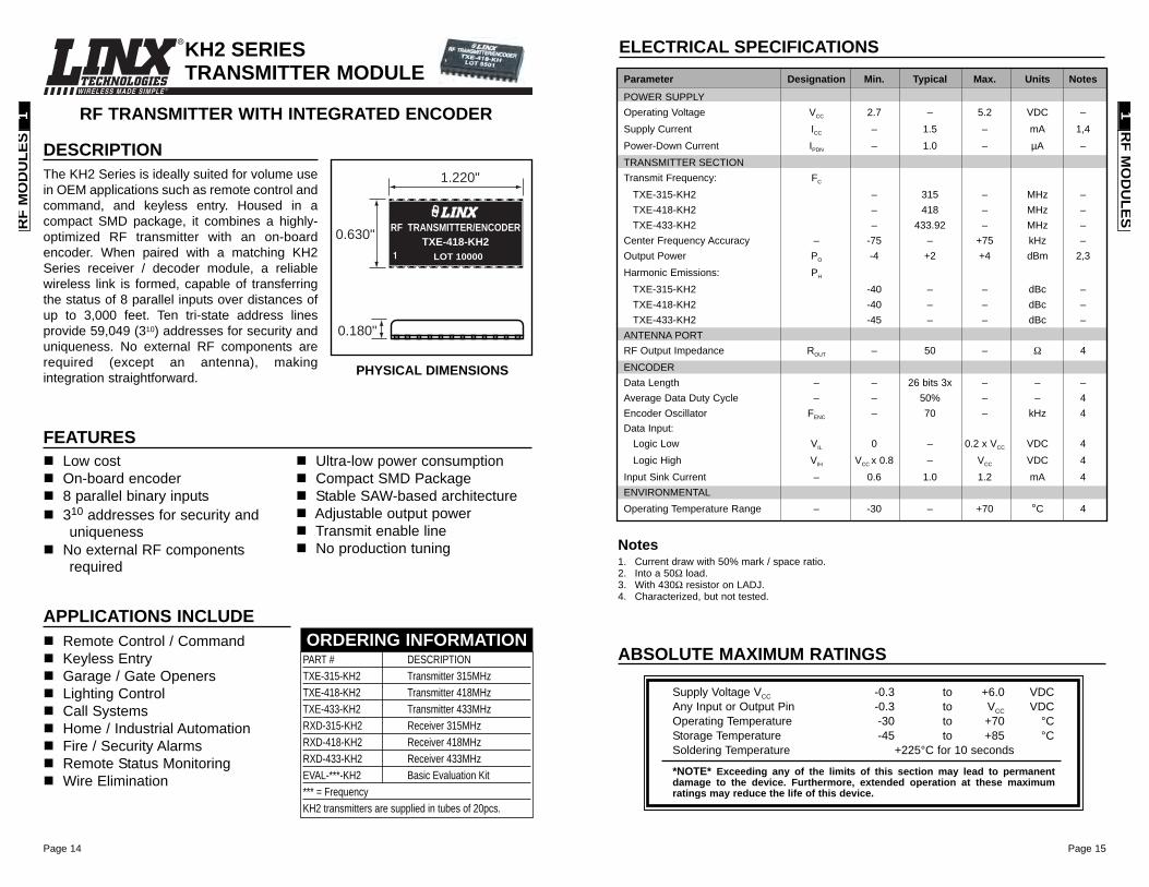
RF TRANSMITTER WITH INTEGRATED ENCODER
KH2 SERIES TRANSMITTER MODULE
DESCRIPTIONThe KH2 Series is ideally suited for volume usein OEM applications such as remote control andcommand, and keyless entry. Housed in acompact SMD package, it combines a highly-optimized RF transmitter with an on-boardencoder. When paired with a matching KH2Series receiver / decoder module, a reliablewireless link is formed, capable of transferringthe status of 8 parallel inputs over distances ofup to 3,000 feet. Ten tri-state address linesprovide 59,049 (310) addresses for security anduniqueness. No external RF components arerequired (except an antenna), makingintegration straightforward.
Remote Control / CommandKeyless EntryGarage / Gate OpenersLighting ControlCall SystemsHome / Industrial AutomationFire / Security AlarmsRemote Status MonitoringWire Elimination
APPLICATIONS INCLUDE
Low cost On-board encoder8 parallel binary inputs 310 addresses for security anduniqueness
No external RF componentsrequired
Ultra-low power consumptionCompact SMD PackageStable SAW-based architectureAdjustable output powerTransmit enable lineNo production tuning
FEATURES
PART # DESCRIPTIONTXE-315-KH2 Transmitter 315MHzTXE-418-KH2 Transmitter 418MHz TXE-433-KH2 Transmitter 433MHzRXD-315-KH2 Receiver 315MHzRXD-418-KH2 Receiver 418MHzRXD-433-KH2 Receiver 433MHzEVAL-***-KH2 Basic Evaluation Kit*** = FrequencyKH2 transmitters are supplied in tubes of 20pcs.
ORDERING INFORMATION
PHYSICAL DIMENSIONS
RF M
OD
ULES
1R
F M
OD
ULE
S1
0.180"
0.630"
1.220"
LOT 10000
RF TRANSMITTER/ENCODERTXE-418-KH2
Page 16
WIRELESS MADE SIMPLE ®
Page 17
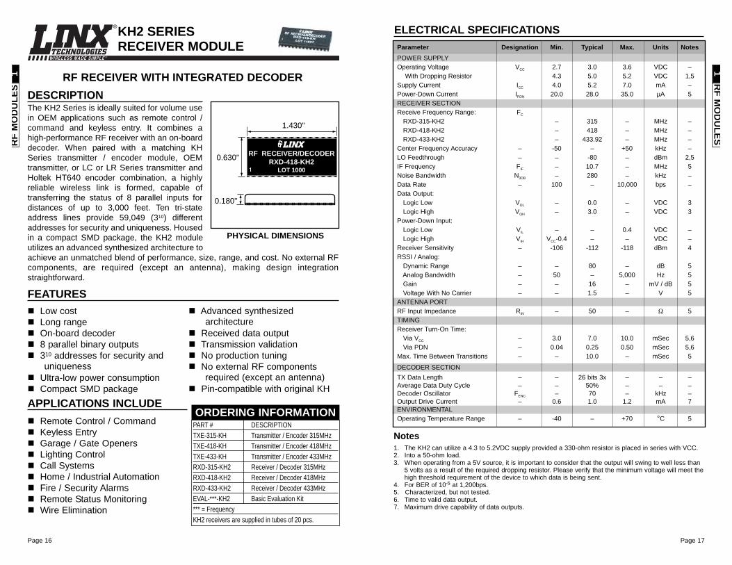
RF RECEIVER WITH INTEGRATED DECODER
KH2 SERIES RECEIVER MODULE
DESCRIPTIONThe KH2 Series is ideally suited for volume usein OEM applications such as remote control /command and keyless entry. It combines ahigh-performance RF receiver with an on-boarddecoder. When paired with a matching KHSeries transmitter / encoder module, OEMtransmitter, or LC or LR Series transmitter andHoltek HT640 encoder combination, a highlyreliable wireless link is formed, capable oftransferring the status of 8 parallel inputs fordistances of up to 3,000 feet. Ten tri-stateaddress lines provide 59,049 (310) differentaddresses for security and uniqueness. Housedin a compact SMD package, the KH2 moduleutilizes an advanced synthesized architecture toachieve an unmatched blend of performance, size, range, and cost. No external RFcomponents, are required (except an antenna), making design integrationstraightforward.
0.630"
1.430"
LOT 1000
RF RECEIVER/DECODER
0.180"
RXD-418-KH2
Remote Control / CommandKeyless EntryGarage / Gate OpenersLighting ControlCall SystemsHome / Industrial AutomationFire / Security AlarmsRemote Status MonitoringWire Elimination
APPLICATIONS INCLUDE
Low costLong rangeOn-board decoder8 parallel binary outputs 310 addresses for security anduniqueness
Ultra-low power consumptionCompact SMD package
Advanced synthesizedarchitecture
Received data outputTransmission validationNo production tuningNo external RF componentsrequired (except an antenna)
Pin-compatible with original KH
FEATURES
PART # DESCRIPTIONTXE-315-KH Transmitter / Encoder 315MHzTXE-418-KH Transmitter / Encoder 418MHz TXE-433-KH Transmitter / Encoder 433MHzRXD-315-KH2 Receiver / Decoder 315MHzRXD-418-KH2 Receiver / Decoder 418MHzRXD-433-KH2 Receiver / Decoder 433MHzEVAL-***-KH2 Basic Evaluation Kit*** = FrequencyKH2 receivers are supplied in tubes of 20 pcs.
ORDERING INFORMATION
PHYSICAL DIMENSIONS
ELECTRICAL SPECIFICATIONS
1. The KH2 can utilize a 4.3 to 5.2VDC supply provided a 330-ohm resistor is placed in series with VCC.2. Into a 50-ohm load.3. When operating from a 5V source, it is important to consider that the output will swing to well less than
5 volts as a result of the required dropping resistor. Please verify that the minimum voltage will meet thehigh threshold requirement of the device to which data is being sent.
4. For BER of 10-5 at 1,200bps.5. Characterized, but not tested.6. Time to valid data output.7. Maximum drive capability of data outputs.
Notes
Parameter Designation Min. Typical Max. Units NotesPOWER SUPPLYOperating Voltage VCC 2.7 3.0 3.6 VDC –
With Dropping Resistor 4.3 5.0 5.2 VDC 1,5Supply Current ICC 4.0 5.2 7.0 mA –Power-Down Current IPDN 20.0 28.0 35.0 µA 5RECEIVER SECTIONReceive Frequency Range: FC
RXD-315-KH2 – 315 – MHz –RXD-418-KH2 – 418 – MHz –RXD-433-KH2 – 433.92 – MHz –
Center Frequency Accuracy – -50 – +50 kHz –LO Feedthrough – – -80 – dBm 2,5IF Frequency FIF – 10.7 – MHz 5Noise Bandwidth N3DB – 280 – kHz –Data Rate – 100 – 10,000 bps –Data Output:
Logic Low VOL – 0.0 – VDC 3Logic High VOH – 3.0 – VDC 3
Power-Down Input:Logic Low VIL – – 0.4 VDC –Logic High VIH VCC-0.4 – – VDC –
Receiver Sensitivity – -106 -112 -118 dBm 4RSSI / Analog:
Dynamic Range – – 80 – dB 5Analog Bandwidth – 50 – 5,000 Hz 5Gain – – 16 – mV / dB 5Voltage With No Carrier – – 1.5 – V 5
ANTENNA PORTRF Input Impedance RIN – 50 – Ω 5TIMINGReceiver Turn-On Time:
Via VCC – 3.0 7.0 10.0 mSec 5,6Via PDN – 0.04 0.25 0.50 mSec 5,6
Max. Time Between Transitions – – 10.0 – mSec 5
DECODER SECTIONTX Data Length – – 26 bits 3x – – –Average Data Duty Cycle – – 50% – – –Decoder Oscillator FENC – 70 – kHz –Output Drive Current – 0.6 1.0 1.2 mA 7ENVIRONMENTALOperating Temperature Range – -40 – +70 °C 5
RF M
OD
ULES
1R
F M
OD
ULE
S1
Page 18
WIRELESS MADE SIMPLE ®
Page 19
ELECTRICAL SPECIFICATIONS
1. Center frequency measured while modulated with a 0-5V square wave.2. Into a 50-ohm load.3. LADJ open.4. Maximum power when LADJ open, minimum power when LADJ grounded.5. DATA pin modulated with a 0-5V square wave.6. The audio bandwidth is wide to accommodate the needs of the data slicer.7. Characterized, but not tested.8. The ES is optimized for both 0-5V and 0-3V modulation when sending digital data.9. Analog signals, including audio, should be AC-coupled.10. Time to transmitter readiness from the application of power to VCC or PDN going high.11. Maximum time without a data transition.
Notes
ABSOLUTE MAXIMUM RATINGSSupply Voltage VCC -0.3 to +4.0 VDCAny Input or Output Pin -0.5 to VCC + 0.5 VDCOperating Temperature 0 to +70 °CStorage Temperature -40 to +90 °CSoldering Temperature +225°C for 10 seconds
*NOTE* Exceeding any of the limits of this section may lead to permanentdamage to the device. Furthermore, extended operation at these maximumratings may reduce the life of this device.
ES SERIES TRANSMITTER MODULE
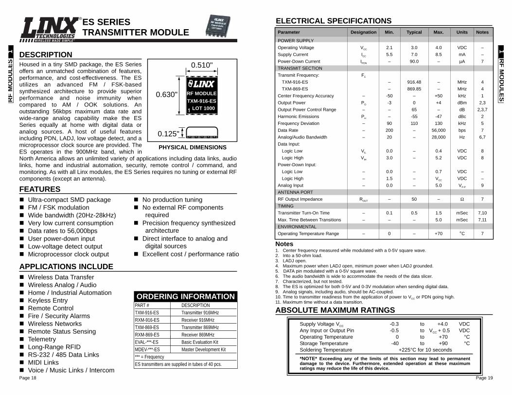
DESCRIPTIONHoused in a tiny SMD package, the ES Seriesoffers an unmatched combination of features,performance, and cost-effectiveness. The ESutilizes an advanced FM / FSK-basedsynthesized architecture to provide superiorperformance and noise immunity whencompared to AM / OOK solutions. Anoutstanding 56kbps maximum data rate andwide-range analog capability make the ESSeries equally at home with digital data oranalog sources. A host of useful featuresincluding PDN, LADJ, low voltage detect, and amicroprocessor clock source are provided. TheES operates in the 900MHz band, which inNorth America allows an unlimited variety of applications including data links, audiolinks, home and industrial automation, security, remote control / command, andmonitoring. As with all Linx modules, the ES Series requires no tuning or external RFcomponents (except an antenna).
0.125"
0.630"
LOT 1000TXM-916-ES
RF MODULE
0.510"
Wireless Data TransferWireless Analog / AudioHome / Industrial AutomationKeyless EntryRemote ControlFire / Security AlarmsWireless NetworksRemote Status SensingTelemetryLong-Range RFIDRS-232 / 485 Data LinksMIDI LinksVoice / Music Links / Intercom
APPLICATIONS INCLUDE
Ultra-compact SMD packageFM / FSK modulationWide bandwidth (20Hz-28kHz)Very low current consumptionData rates to 56,000bpsUser power-down inputLow-voltage detect outputMicroprocessor clock output
No production tuningNo external RF componentsrequired
Precision frequency synthesizedarchitecture
Direct interface to analog anddigital sources
Excellent cost / performance ratio
FEATURES
PART # DESCRIPTIONTXM-916-ES Transmitter 916MHzRXM-916-ES Receiver 916MHzTXM-869-ES Transmitter 869MHzRXM-869-ES Receiver 869MHzEVAL-***-ES Basic Evaluation KitMDEV-***-ES Master Development Kit*** = FrequencyES transmitters are supplied in tubes of 40 pcs.
ORDERING INFORMATION
PHYSICAL DIMENSIONS
Parameter Designation Min. Typical Max. Units Notes
POWER SUPPLYOperating Voltage VCC 2.1 3.0 4.0 VDC –Supply Current ICC 5.5 7.0 8.5 mA –Power-Down Current IPDN – 90.0 – µA 7TRANSMIT SECTIONTransmit Frequency: FC
TXM-916-ES – 916.48 – MHz 4TXM-869-ES – 869.85 – MHz 4
Center Frequency Accuracy – -50 – +50 kHz 1Output Power PO -3 0 +4 dBm 2,3Output Power Control Range – – 65 – dB 2,3,7Harmonic Emissions PH – -55 -47 dBc 2Frequency Deviation – 90 110 130 kHz 5Data Rate – 200 – 56,000 bps 7Analog/Audio Bandwidth – 20 – 28,000 Hz 6,7Data Input:
Logic Low VIL 0.0 – 0.4 VDC 8Logic High VIH 3.0 – 5.2 VDC 8
Power-Down Input:Logic Low – 0.0 – 0.7 VDC –Logic High – 1.5 – VCC VDC –
Analog Input – 0.0 – 5.0 VP-P 9ANTENNA PORTRF Output Impedance ROUT – 50 – Ω 7TIMINGTransmitter Turn-On Time – 0.1 0.5 1.5 mSec 7,10Max. Time Between Transitions – – – 5.0 mSec 7,11ENVIRONMENTALOperating Temperature Range – 0 – +70 °C 7
RF M
OD
ULES
1R
F M
OD
ULE
S1
Page 20
WIRELESS MADE SIMPLE ®
Page 21
1. Into a 50-ohm load.2. For a 10-5 BER at 9,600bps.3. The audio bandwidth is wide to accommodate the needs of the data slicer. In audio applications, audio
quality may be improved by using a low-pass filter rolling off at the maximum frequency of interest.4. Characterized, but not tested.5. Input frequency deviation-dependent.6. Time to receiver readiness from the application of power to VCC or PDN going high. 7. Maximum time without a data transition.
Notes
ABSOLUTE MAXIMUM RATINGSSupply Voltage VCC -0.3 to +5.5 VDCAny Input or Output Pin -0.3 to VCC + 0.3 VDCRF Input +10 dBmOperating Temperature 0 to +70 °CStorage Temperature -40 to +125 °CSoldering Temperature +225°C for 10 seconds
*NOTE* Exceeding any of the limits of this section may lead to permanentdamage to the device. Furthermore, extended operation at these maximumratings may reduce the life of this device.
ES SERIES RECEIVER MODULE
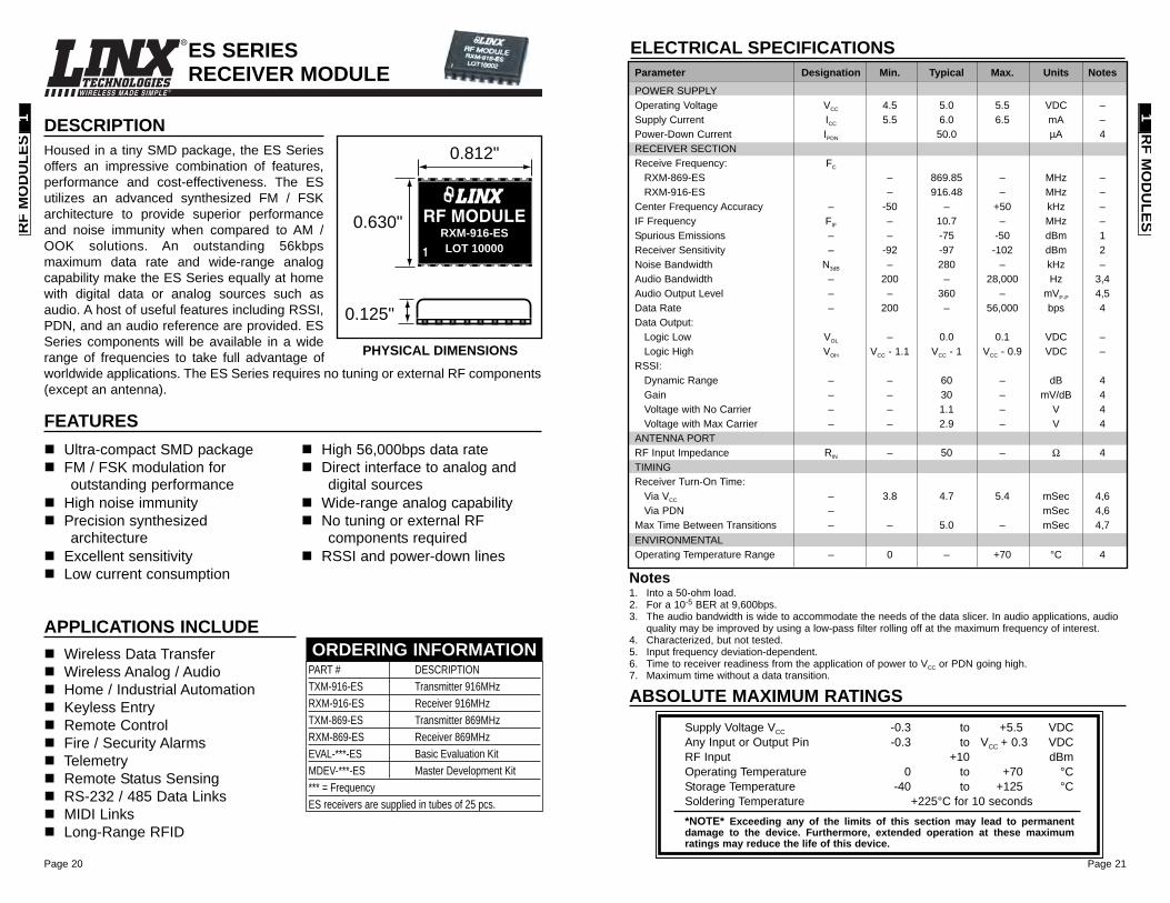
DESCRIPTIONHoused in a tiny SMD package, the ES Seriesoffers an impressive combination of features,performance and cost-effectiveness. The ESutilizes an advanced synthesized FM / FSKarchitecture to provide superior performanceand noise immunity when compared to AM /OOK solutions. An outstanding 56kbpsmaximum data rate and wide-range analogcapability make the ES Series equally at homewith digital data or analog sources such asaudio. A host of useful features including RSSI,PDN, and an audio reference are provided. ESSeries components will be available in a widerange of frequencies to take full advantage ofworldwide applications. The ES Series requires no tuning or external RF components(except an antenna).
0.125"
0.630"LOT 10000
RXM-916-ESRF MODULE
0.812"
Wireless Data TransferWireless Analog / AudioHome / Industrial AutomationKeyless EntryRemote ControlFire / Security AlarmsTelemetryRemote Status SensingRS-232 / 485 Data LinksMIDI LinksLong-Range RFID
APPLICATIONS INCLUDE
Ultra-compact SMD packageFM / FSK modulation foroutstanding performance
High noise immunityPrecision synthesizedarchitecture
Excellent sensitivityLow current consumption
High 56,000bps data rateDirect interface to analog anddigital sources
Wide-range analog capabilityNo tuning or external RFcomponents required
RSSI and power-down lines
FEATURES
PHYSICAL DIMENSIONS
ELECTRICAL SPECIFICATIONSParameter Designation Min. Typical Max. Units Notes
POWER SUPPLYOperating Voltage VCC 4.5 5.0 5.5 VDC –Supply Current ICC 5.5 6.0 6.5 mA –Power-Down Current IPDN 50.0 µA 4RECEIVER SECTIONReceive Frequency: FC
RXM-869-ES – 869.85 – MHz –RXM-916-ES – 916.48 – MHz –
Center Frequency Accuracy – -50 – +50 kHz –IF Frequency FIF – 10.7 – MHz –Spurious Emissions – – -75 -50 dBm 1Receiver Sensitivity – -92 -97 -102 dBm 2Noise Bandwidth N3dB – 280 – kHz –Audio Bandwidth – 200 – 28,000 Hz 3,4Audio Output Level – – 360 – mVP-P 4,5Data Rate – 200 – 56,000 bps 4Data Output:
Logic Low VOL – 0.0 0.1 VDC –Logic High VOH VCC - 1.1 VCC - 1 VCC - 0.9 VDC –
RSSI:Dynamic Range – – 60 – dB 4Gain – – 30 – mV/dB 4Voltage with No Carrier – – 1.1 – V 4Voltage with Max Carrier – – 2.9 – V 4
ANTENNA PORTRF Input Impedance RIN – 50 – Ω 4TIMINGReceiver Turn-On Time:
Via VCC – 3.8 4.7 5.4 mSec 4,6Via PDN – mSec 4,6
Max Time Between Transitions – – 5.0 – mSec 4,7ENVIRONMENTALOperating Temperature Range – 0 – +70 °C 4
PART # DESCRIPTIONTXM-916-ES Transmitter 916MHzRXM-916-ES Receiver 916MHzTXM-869-ES Transmitter 869MHzRXM-869-ES Receiver 869MHzEVAL-***-ES Basic Evaluation KitMDEV-***-ES Master Development Kit*** = FrequencyES receivers are supplied in tubes of 25 pcs.
ORDERING INFORMATION
RF M
OD
ULES
1R
F M
OD
ULE
S1
Page 22 Page 23
WIRELESS MADE SIMPLE ®
ABSOLUTE MAXIMUM RATINGS
Supply Voltage VCC -0.3 to +18.0 VDCAny Input or Output Pin -0.3 to VCC VDCOperating Temperature -30 to +85 °CStorage Temperature -45 to +85 °CSoldering Temperature +260°C for 10 seconds
*NOTE* Exceeding any of the limits of this section may lead to permanentdamage to the device. Furthermore, extended operation at these maximumratings may reduce the life of this device.
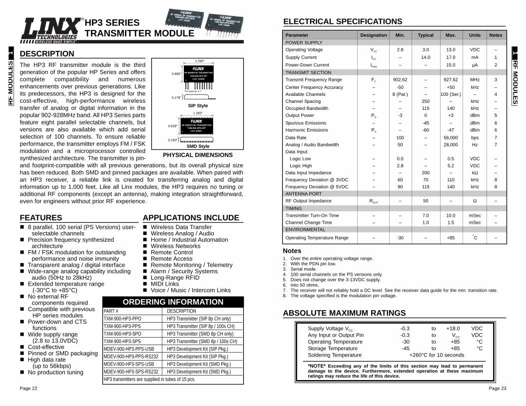
ELECTRICAL SPECIFICATIONSParameter Designation Min. Typical Max. Units NotesPOWER SUPPLYOperating Voltage VCC 2.8 3.0 13.0 VDC –Supply Current ICC – 14.0 17.0 mA 1Power-Down Current IPDN – – 15.0 µA 2TRANSMIT SECTIONTransmit Frequency Range FC 902.62 – 927.62 MHz 3Center Frequency Accuracy – -50 – +50 kHz –Available Channels – 8 (Par.) – 100 (Ser.) – 4Channel Spacing – – 250 – kHz –Occupied Bandwidth – – 115 140 kHz –Output Power PO -3 0 +3 dBm 5Spurious Emissions – – -45 – dBm 6Harmonic Emissions PH – -60 -47 dBm 6Data Rate – 100 – 56,000 bps 7Analog / Audio Bandwidth – 50 – 28,000 Hz 7Data Input:
Logic Low – 0.0 – 0.5 VDC –Logic High – 2.8 – 5.2 VDC –
Data Input Impedance – – 200 – kΩ –Frequency Deviation @ 3VDC – 60 70 110 kHz 8Frequency Deviation @ 5VDC – 90 115 140 kHz 8ANTENNA PORTRF Output Impedance ROUT – 50 – Ω –TIMINGTransmitter Turn-On Time – – 7.0 10.0 mSec –Channel Change Time – – 1.0 1.5 mSec –ENVIRONMENTAL
Operating Temperature Range – -30 – +85 °C –
1. Over the entire operating voltage range.2. With the PDN pin low.3. Serial mode.4. 100 serial channels on the PS versions only.5. Does not change over the 3-13VDC supply.6. Into 50 ohms. 7. The receiver will not reliably hold a DC level. See the receiver data guide for the min. transition rate.8. The voltage specified is the modulation pin voltage.
Notes
FEATURES8 parallel, 100 serial (PS Versions) user-
selectable channels Precision frequency synthesized
architectureFM / FSK modulation for outstanding
performance and noise immunityTransparent analog / digital interfaceWide-range analog capability including
audio (50Hz to 28kHz)Extended temperature range
(-30°C to +85°C)No external RF
components requiredCompatible with previous
HP series modulesPower-down and CTS
functionsWide supply range
(2.8 to 13.0VDC) Cost-effectivePinned or SMD packagingHigh data rate
(up to 56kbps)No production tuning
HP3 SERIESTRANSMITTER MODULE
APPLICATIONS INCLUDEWireless Data TransferWireless Analog / AudioHome / Industrial AutomationWireless NetworksRemote Control Remote AccessRemote Monitoring / TelemetryAlarm / Security SystemsLong-Range RFIDMIDI LinksVoice / Music / Intercom Links
PART # DESCRIPTIONTXM-900-HP3-PPO HP3 Transmitter (SIP 8p CH only)TXM-900-HP3-PPS HP3 Transmitter (SIP 8p / 100s CH)TXM-900-HP3-SPO HP3 Transmitter (SMD 8p CH only)TXM-900-HP3-SPS HP3 Transmitter (SMD 8p / 100s CH)MDEV-900-HP3-PPS-USB HP3 Development Kit (SIP Pkg.)MDEV-900-HP3-PPS-RS232 HP3 Development Kit (SIP Pkg.)MDEV-900-HP3-SPS-USB HP3 Development Kit (SMD Pkg.)MDEV-900-HP3-SPS-RS232 HP3 Development Kit (SMD Pkg.)HP3 transmitters are supplied in tubes of 15 pcs.
ORDERING INFORMATION
DESCRIPTIONThe HP3 RF transmitter module is the thirdgeneration of the popular HP Series and offerscomplete compatibility and numerousenhancements over previous generations. Likeits predecessors, the HP3 is designed for thecost-effective, high-performance wirelesstransfer of analog or digital information in thepopular 902-928MHz band. All HP3 Series partsfeature eight parallel selectable channels, butversions are also available which add serialselection of 100 channels. To ensure reliableperformance, the transmitter employs FM / FSKmodulation and a microprocessor controlledsynthesized architecture. The transmitter is pin-and footprint-compatible with all previous generations, but its overall physical sizehas been reduced. Both SMD and pinned packages are available. When paired withan HP3 receiver, a reliable link is created for transferring analog and digitalinformation up to 1,000 feet. Like all Linx modules, the HP3 requires no tuning oradditional RF components (except an antenna), making integration straightforward,even for engineers without prior RF experience.
0.150"
0.628"LOT 10000
TXM-900-HP3-SP*HP SERIES RF TRANSMITTER
1.260"
LOT 10000TXM-900-HP3-SP*
HP SERIES RF TRANSMITTER0.680"
1.290"
0.178"
Pin Spacing: 0.1"
PHYSICAL DIMENSIONSSMD Style
SIP Style
RF M
OD
ULES
1R
F M
OD
ULE
S1
Page 24
WIRELESS MADE SIMPLE ®
Page 25
1. Over entire operating voltage range.2. No load.3. With a 1V output drop.4. Serial mode.5. With 1kHz sine wave at 115kHz transmitter deviation.6. For a 10-5 BER at 9,600bps.7. At specified center frequency.8. Units are not rejected for better than maximum sensitivity.9. Minimum input power level to ensure that data output can hold a DC level.
Notes
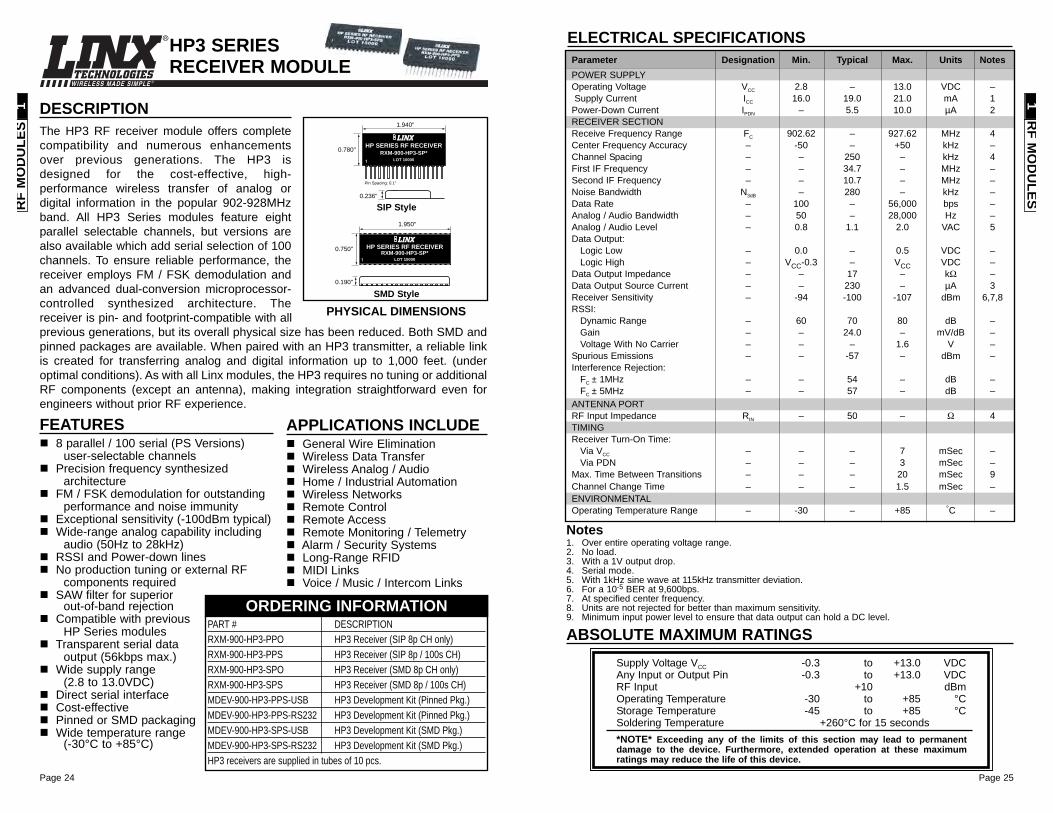
ELECTRICAL SPECIFICATIONSParameter Designation Min. Typical Max. Units NotesPOWER SUPPLYOperating Voltage VCC 2.8 – 13.0 VDC –Supply Current ICC 16.0 19.0 21.0 mA 1
Power-Down Current IPDN – 5.5 10.0 µA 2RECEIVER SECTIONReceive Frequency Range FC 902.62 – 927.62 MHz 4Center Frequency Accuracy – -50 – +50 kHz –Channel Spacing – – 250 – kHz 4First IF Frequency – – 34.7 – MHz –Second IF Frequency – – 10.7 – MHz –Noise Bandwidth N3dB – 280 – kHz –Data Rate – 100 – 56,000 bps –Analog / Audio Bandwidth – 50 – 28,000 Hz –Analog / Audio Level – 0.8 1.1 2.0 VAC 5Data Output:
Logic Low – 0.0 – 0.5 VDC –Logic High – VCC-0.3 – VCC VDC –
Data Output Impedance – – 17 – kΩ –Data Output Source Current – – 230 – µA 3Receiver Sensitivity – -94 -100 -107 dBm 6,7,8RSSI:
Dynamic Range – 60 70 80 dB –Gain – – 24.0 – mV/dB –Voltage With No Carrier – – – 1.6 V –
Spurious Emissions – – -57 – dBm –Interference Rejection:
FC ± 1MHz – – 54 – dB –FC ± 5MHz – – 57 – dB –
ANTENNA PORTRF Input Impedance RIN – 50 – Ω 4TIMINGReceiver Turn-On Time:
Via VCC – – – 7 mSec –Via PDN – – – 3 mSec –
Max. Time Between Transitions – – – 20 mSec 9Channel Change Time – – – 1.5 mSec –ENVIRONMENTALOperating Temperature Range – -30 – +85 °C –
ABSOLUTE MAXIMUM RATINGSSupply Voltage VCC -0.3 to +13.0 VDCAny Input or Output Pin -0.3 to +13.0 VDCRF Input +10 dBmOperating Temperature -30 to +85 °CStorage Temperature -45 to +85 °CSoldering Temperature +260°C for 15 seconds*NOTE* Exceeding any of the limits of this section may lead to permanentdamage to the device. Furthermore, extended operation at these maximumratings may reduce the life of this device.
HP3 SERIESRECEIVER MODULE
APPLICATIONS INCLUDEGeneral Wire EliminationWireless Data TransferWireless Analog / AudioHome / Industrial AutomationWireless NetworksRemote Control Remote AccessRemote Monitoring / TelemetryAlarm / Security SystemsLong-Range RFIDMIDI LinksVoice / Music / Intercom Links
FEATURES8 parallel / 100 serial (PS Versions)
user-selectable channelsPrecision frequency synthesized
architectureFM / FSK demodulation for outstanding
performance and noise immunityExceptional sensitivity (-100dBm typical)Wide-range analog capability including
audio (50Hz to 28kHz)RSSI and Power-down linesNo production tuning or external RF
components required SAW filter for superior
out-of-band rejectionCompatible with previous
HP Series modulesTransparent serial data
output (56kbps max.)Wide supply range
(2.8 to 13.0VDC) Direct serial interfaceCost-effectivePinned or SMD packagingWide temperature range
(-30°C to +85°C)
PART # DESCRIPTIONRXM-900-HP3-PPO HP3 Receiver (SIP 8p CH only)RXM-900-HP3-PPS HP3 Receiver (SIP 8p / 100s CH)RXM-900-HP3-SPO HP3 Receiver (SMD 8p CH only)RXM-900-HP3-SPS HP3 Receiver (SMD 8p / 100s CH)MDEV-900-HP3-PPS-USB HP3 Development Kit (Pinned Pkg.)MDEV-900-HP3-PPS-RS232 HP3 Development Kit (Pinned Pkg.)MDEV-900-HP3-SPS-USB HP3 Development Kit (SMD Pkg.)MDEV-900-HP3-SPS-RS232 HP3 Development Kit (SMD Pkg.)HP3 receivers are supplied in tubes of 10 pcs.
ORDERING INFORMATION
DESCRIPTIONThe HP3 RF receiver module offers completecompatibility and numerous enhancementsover previous generations. The HP3 isdesigned for the cost-effective, high-performance wireless transfer of analog ordigital information in the popular 902-928MHzband. All HP3 Series modules feature eightparallel selectable channels, but versions arealso available which add serial selection of 100channels. To ensure reliable performance, thereceiver employs FM / FSK demodulation andan advanced dual-conversion microprocessor-controlled synthesized architecture. Thereceiver is pin- and footprint-compatible with allprevious generations, but its overall physical size has been reduced. Both SMD andpinned packages are available. When paired with an HP3 transmitter, a reliable linkis created for transferring analog and digital information up to 1,000 feet. (underoptimal conditions). As with all Linx modules, the HP3 requires no tuning or additionalRF components (except an antenna), making integration straightforward even forengineers without prior RF experience.
LOT 10000
RXM-900-HP3-SP*HP SERIES RF RECEIVER
Pin Spacing: 0.1"
0.236"
0.780"
1.940"
0.190"
0.750"
LOT 10000RXM-900-HP3-SP*
HP SERIES RF RECEIVER
1.950"
PHYSICAL DIMENSIONSSMD Style
SIP Style
RF M
OD
ULES
1R
F M
OD
ULE
S1

Page 27Page 26
Your Fast Track To Wireless Success
Evaluation / Development Systems put you on the fast track to wireless success.Each kit contains everything necessary to evaluate the Linx module family of yourchoice and then integrate it into your product in record time. Clear documentation willguide you through the legal and technical issues of application while pre-populatedevaluation boards allow immediate module operation under actual field conditions.Finally, when you have integrated the modules into your own product, the kit willcontinue to serve as a valuable benchmark to compare the performance of your ownlayout and design. In addition, you’ll receive unlimited no-charge technical supportthroughout the entire design process.
*IMPORTANT NOTE*Linx requires the purchase of an evaluation kit of a module series (LT, LC, LR, KH2,ES, HP3, QS) prior to selling individual modules of that series to a user. There aremany reasons for this policy, but the most important is that we want you to have allthe tools necessary to correctly and legally bring wireless function to your product.Evaluation kits serve as a point of reference among all of our customers and allow usto more effectively assist in explaining layout concepts or in troubleshootingapplication difficulties.
DEVELOPMENT SYSTEMS 2
EVALUATION KITS / DEVELOPMENT SYSTEMSPART # DESCRIPTION PG.EVAL-***-LT LT Series Basic Evaluation Kit 28EVAL-***-LC LC Series Basic Evaluation Kit 29EVAL-***-LR LR Series Basic Evaluation Kit 29EVAL-***-KH2 KH2 Series Basic Evaluation Kit 30EVAL-***-ES ES Series Basic Evaluation Kit 30MDEV-***-ES ES Series Master Development System 32MDEV-900-HP3-xxx-RS232 HP3 Series Master Development System (RS-232) 33MDEV-900-HP3-xxx-USB HP3 Series Master Development System (USB) 33*** See Ordering Information for available frequencies
Page 29Page 28
WIRELESS MADE SIMPLE ®
EVALUATION KITSWIRELESS MADE SIMPLE ®
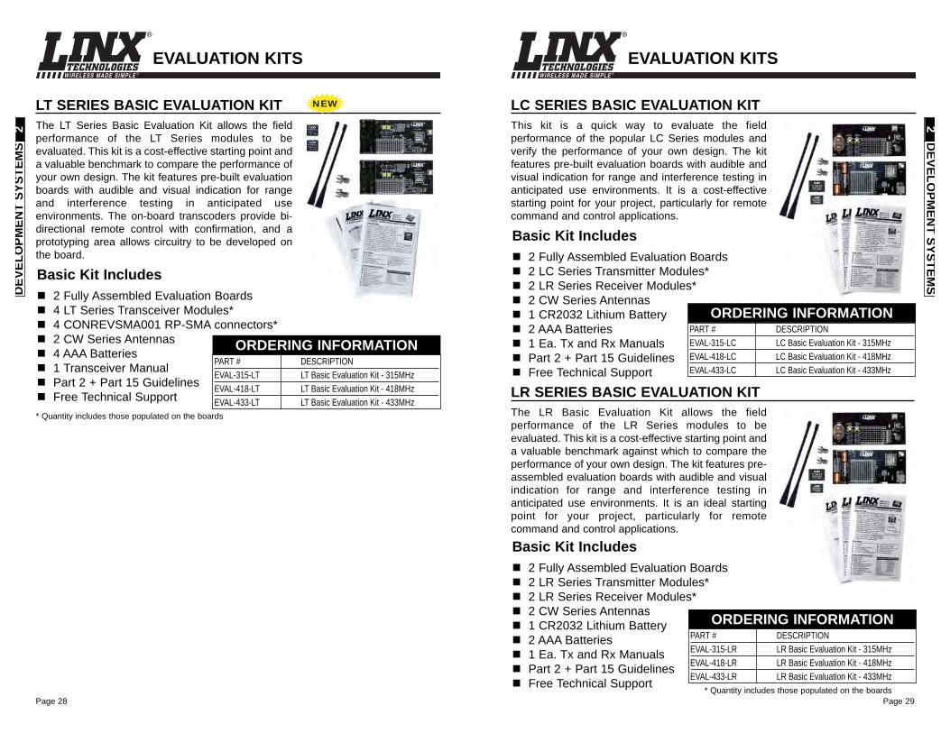
LC SERIES BASIC EVALUATION KITThis kit is a quick way to evaluate the fieldperformance of the popular LC Series modules andverify the performance of your own design. The kitfeatures pre-built evaluation boards with audible andvisual indication for range and interference testing inanticipated use environments. It is a cost-effectivestarting point for your project, particularly for remotecommand and control applications.
Basic Kit Includes2 Fully Assembled Evaluation Boards2 LC Series Transmitter Modules*2 LR Series Receiver Modules*2 CW Series Antennas1 CR2032 Lithium Battery2 AAA Batteries1 Ea. Tx and Rx ManualsPart 2 + Part 15 GuidelinesFree Technical Support
PART # DESCRIPTION EVAL-315-LC LC Basic Evaluation Kit - 315MHzEVAL-418-LC LC Basic Evaluation Kit - 418MHzEVAL-433-LC LC Basic Evaluation Kit - 433MHz
ORDERING INFORMATION
LR SERIES BASIC EVALUATION KITThe LR Basic Evaluation Kit allows the fieldperformance of the LR Series modules to beevaluated. This kit is a cost-effective starting point anda valuable benchmark against which to compare theperformance of your own design. The kit features pre-assembled evaluation boards with audible and visualindication for range and interference testing inanticipated use environments. It is an ideal startingpoint for your project, particularly for remotecommand and control applications.
Basic Kit Includes2 Fully Assembled Evaluation Boards2 LR Series Transmitter Modules*2 LR Series Receiver Modules*2 CW Series Antennas1 CR2032 Lithium Battery2 AAA Batteries1 Ea. Tx and Rx ManualsPart 2 + Part 15 GuidelinesFree Technical Support
EVALUATION KITS
PART # DESCRIPTION EVAL-315-LR LR Basic Evaluation Kit - 315MHzEVAL-418-LR LR Basic Evaluation Kit - 418MHzEVAL-433-LR LR Basic Evaluation Kit - 433MHz
ORDERING INFORMATION
* Quantity includes those populated on the boards
DEVELO
PMEN
T SYSTEMS
2D
EVEL
OPM
ENT
SYST
EMS
2
LT SERIES BASIC EVALUATION KITThe LT Series Basic Evaluation Kit allows the fieldperformance of the LT Series modules to beevaluated. This kit is a cost-effective starting point anda valuable benchmark to compare the performance ofyour own design. The kit features pre-built evaluationboards with audible and visual indication for rangeand interference testing in anticipated useenvironments. The on-board transcoders provide bi-directional remote control with confirmation, and aprototyping area allows circuitry to be developed onthe board.
Basic Kit Includes2 Fully Assembled Evaluation Boards4 LT Series Transceiver Modules*4 CONREVSMA001 RP-SMA connectors*2 CW Series Antennas4 AAA Batteries1 Transceiver ManualPart 2 + Part 15 GuidelinesFree Technical Support
PART # DESCRIPTION EVAL-315-LT LT Basic Evaluation Kit - 315MHzEVAL-418-LT LT Basic Evaluation Kit - 418MHzEVAL-433-LT LT Basic Evaluation Kit - 433MHz
ORDERING INFORMATION
* Quantity includes those populated on the boards
NEW
Page 31
WIRELESS MADE SIMPLE ®
Page 30
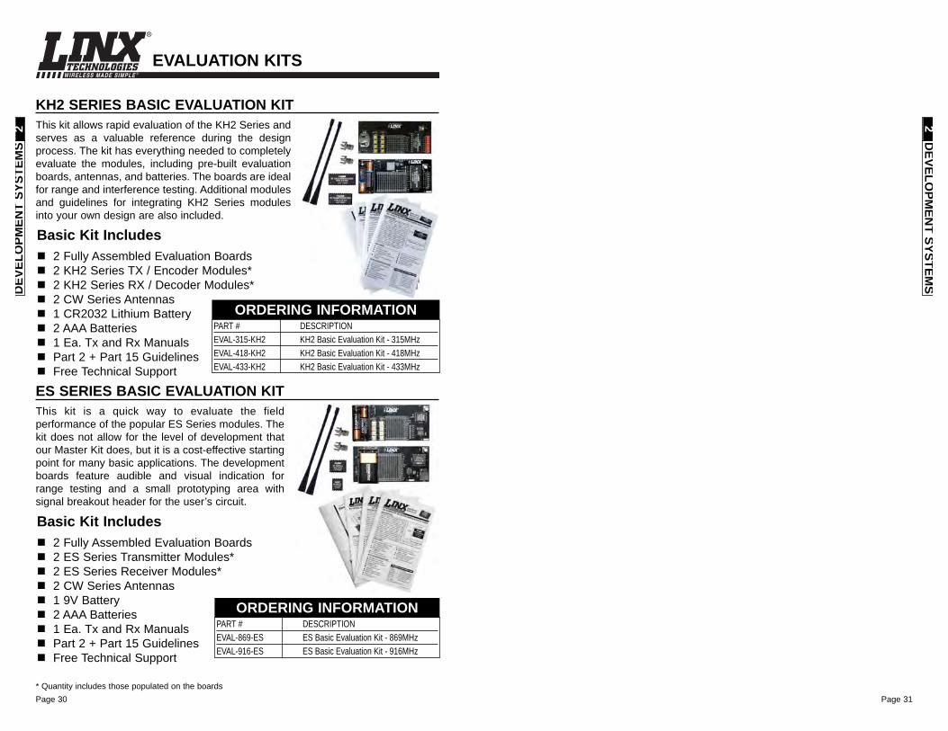
KH2 SERIES BASIC EVALUATION KITThis kit allows rapid evaluation of the KH2 Series andserves as a valuable reference during the designprocess. The kit has everything needed to completelyevaluate the modules, including pre-built evaluationboards, antennas, and batteries. The boards are idealfor range and interference testing. Additional modulesand guidelines for integrating KH2 Series modulesinto your own design are also included.
EVALUATION KITS
PART # DESCRIPTION EVAL-315-KH2 KH2 Basic Evaluation Kit - 315MHzEVAL-418-KH2 KH2 Basic Evaluation Kit - 418MHzEVAL-433-KH2 KH2 Basic Evaluation Kit - 433MHz
ORDERING INFORMATION
Basic Kit Includes2 Fully Assembled Evaluation Boards2 KH2 Series TX / Encoder Modules*2 KH2 Series RX / Decoder Modules*2 CW Series Antennas1 CR2032 Lithium Battery2 AAA Batteries1 Ea. Tx and Rx ManualsPart 2 + Part 15 GuidelinesFree Technical Support
ES SERIES BASIC EVALUATION KITThis kit is a quick way to evaluate the fieldperformance of the popular ES Series modules. Thekit does not allow for the level of development thatour Master Kit does, but it is a cost-effective startingpoint for many basic applications. The developmentboards feature audible and visual indication forrange testing and a small prototyping area withsignal breakout header for the user’s circuit.
Basic Kit Includes2 Fully Assembled Evaluation Boards2 ES Series Transmitter Modules*2 ES Series Receiver Modules*2 CW Series Antennas1 9V Battery2 AAA Batteries1 Ea. Tx and Rx ManualsPart 2 + Part 15 GuidelinesFree Technical Support
PART # DESCRIPTION EVAL-869-ES ES Basic Evaluation Kit - 869MHzEVAL-916-ES ES Basic Evaluation Kit - 916MHz
ORDERING INFORMATION
* Quantity includes those populated on the boards
DEVELO
PMEN
T SYSTEMS
2D
EVEL
OPM
ENT
SYST
EMS
2
Page 33
WIRELESS MADE SIMPLE ®
Page 32
WIRELESS MADE SIMPLE ®
DEVELOPMENT SYSTEMS
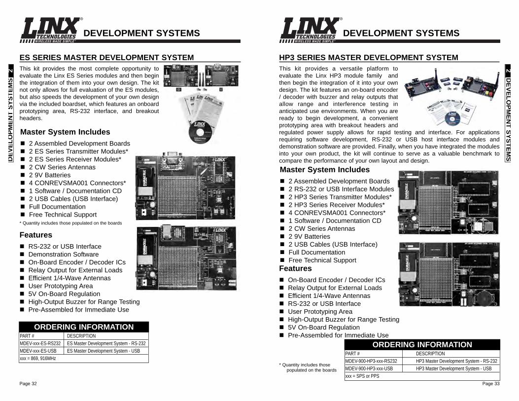
HP3 SERIES MASTER DEVELOPMENT SYSTEMThis kit provides a versatile platform toevaluate the Linx HP3 module family andthen begin the integration of it into your owndesign. The kit features an on-board encoder/ decoder with buzzer and relay outputs thatallow range and interference testing inanticipated use environments. When you areready to begin development, a convenientprototyping area with breakout headers andregulated power supply allows for rapid testing and interface. For applicationsrequiring software development, RS-232 or USB host interface modules anddemonstration software are provided. Finally, when you have integrated the modulesinto your own product, the kit will continue to serve as a valuable benchmark tocompare the performance of your own layout and design.Master System Includes
2 Assembled Development Boards2 RS-232 or USB Interface Modules2 HP3 Series Transmitter Modules*2 HP3 Series Receiver Modules*4 CONREVSMA001 Connectors*1 Software / Documentation CD2 CW Series Antennas2 9V Batteries2 USB Cables (USB Interface)Full DocumentationFree Technical Support
FeaturesOn-Board Encoder / Decoder ICsRelay Output for External Loads Efficient 1/4-Wave AntennasRS-232 or USB InterfaceUser Prototyping AreaHigh-Output Buzzer for Range Testing5V On-Board RegulationPre-Assembled for Immediate Use
PART # DESCRIPTIONMDEV-900-HP3-xxx-RS232 HP3 Master Development System - RS-232MDEV-900-HP3-xxx-USB HP3 Master Development System - USBxxx = SPS or PPS
ORDERING INFORMATION
DEVELO
PMEN
T SYSTEMS
2
ES SERIES MASTER DEVELOPMENT SYSTEMThis kit provides the most complete opportunity toevaluate the Linx ES Series modules and then beginthe integration of them into your own design. The kitnot only allows for full evaluation of the ES modules,but also speeds the development of your own designvia the included boardset, which features an onboardprototyping area, RS-232 interface, and breakoutheaders.
FeaturesRS-232 or USB InterfaceDemonstration SoftwareOn-Board Encoder / Decoder ICsRelay Output for External Loads Efficient 1/4-Wave AntennasUser Prototyping Area5V On-Board RegulationHigh-Output Buzzer for Range TestingPre-Assembled for Immediate Use
DEVELOPMENT SYSTEMS
Master System Includes2 Assembled Development Boards2 ES Series Transmitter Modules*2 ES Series Receiver Modules*2 CW Series Antennas2 9V Batteries4 CONREVSMA001 Connectors*1 Software / Documentation CD2 USB Cables (USB Interface)Full DocumentationFree Technical Support
* Quantity includes those populated on the boards
DEV
ELO
PMEN
T SY
STEM
S2
* Quantity includes thosepopulated on the boards
PART # DESCRIPTIONMDEV-xxx-ES-RS232 ES Master Development System - RS-232MDEV-xxx-ES-USB ES Master Development System - USBxxx = 869, 916MHz
ORDERING INFORMATION
Page 35Page 34
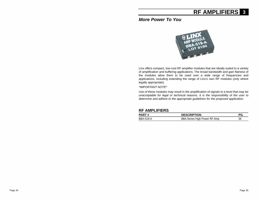
Linx offers compact, low-cost RF amplifier modules that are ideally suited to a varietyof amplification and buffering applications. The broad bandwidth and gain flatness ofthe modules allow them to be used over a wide range of frequencies andapplications, including extending the range of Linx’s own RF modules (only wherelegally appropriate). *IMPORTANT NOTE* Use of these modules may result in the amplification of signals to a level that may beunacceptable for legal or technical reasons. It is the responsibility of the user todetermine and adhere to the appropriate guidelines for the proposed application.
RF AMPLIFIERS 3
RF AMPLIFIERSPART # DESCRIPTION PG.BBA-519-A BBA Series High Power RF Amp 36
More Power To You
Page 37Page 36
RF A
MPLIFIER
S3
RF
AM
PLIF
IER
S3
WIRELESS MADE SIMPLE ®
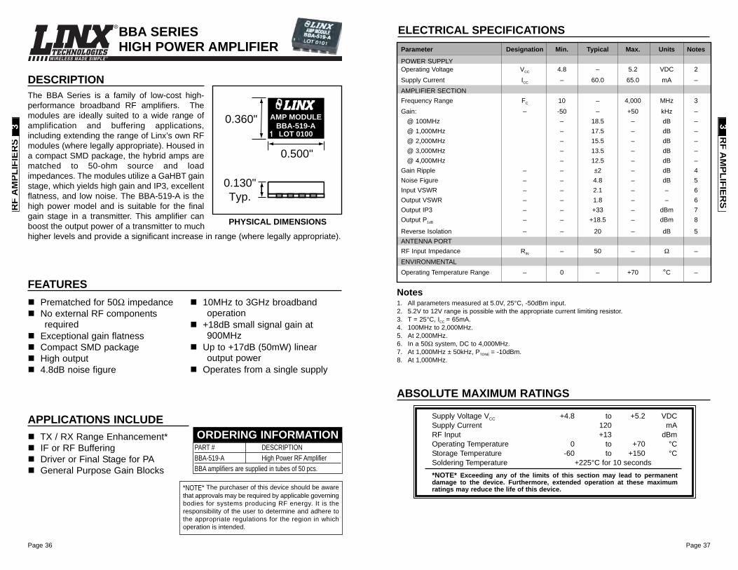
1. All parameters measured at 5.0V, 25°C, -50dBm input.2. 5.2V to 12V range is possible with the appropriate current limiting resistor.3. T = 25°C, ICC = 65mA.4. 100MHz to 2,000MHz.5. At 2,000MHz.6. In a 50Ω system, DC to 4,000MHz.7. At 1,000MHz ± 50kHz, PTONE = -10dBm.8. At 1,000MHz.
Notes
ELECTRICAL SPECIFICATIONSParameter Designation Min. Typical Max. Units Notes
POWER SUPPLYOperating Voltage VCC 4.8 – 5.2 VDC 2Supply Current ICC – 60.0 65.0 mA –AMPLIFIER SECTIONFrequency Range FC 10 – 4,000 MHz 3Gain: – -50 – +50 kHz –
@ 100MHz – 18.5 – dB –@ 1,000MHz – 17.5 – dB –@ 2,000MHz – 15.5 – dB –@ 3,000MHz – 13.5 – dB –@ 4,000MHz – 12.5 – dB –
Gain Ripple – – ±2 – dB 4Noise Figure – – 4.8 – dB 5Input VSWR – – 2.1 – – 6Output VSWR – – 1.8 – – 6Output IP3 – – +33 – dBm 7Output P1dB – – +18.5 – dBm 8
Reverse Isolation – – 20 – dB 5ANTENNA PORTRF Input Impedance RIN – 50 – Ω –ENVIRONMENTALOperating Temperature Range – 0 – +70 °C –
ABSOLUTE MAXIMUM RATINGS
Supply Voltage VCC +4.8 to +5.2 VDCSupply Current 120 mARF Input +13 dBmOperating Temperature 0 to +70 °CStorage Temperature -60 to +150 °CSoldering Temperature +225°C for 10 seconds
*NOTE* Exceeding any of the limits of this section may lead to permanentdamage to the device. Furthermore, extended operation at these maximumratings may reduce the life of this device.
DESCRIPTIONThe BBA Series is a family of low-cost high-performance broadband RF amplifiers. Themodules are ideally suited to a wide range ofamplification and buffering applications,including extending the range of Linx’s own RFmodules (where legally appropriate). Housed ina compact SMD package, the hybrid amps arematched to 50-ohm source and loadimpedances. The modules utilize a GaHBT gainstage, which yields high gain and IP3, excellentflatness, and low noise. The BBA-519-A is thehigh power model and is suitable for the finalgain stage in a transmitter. This amplifier canboost the output power of a transmitter to muchhigher levels and provide a significant increase in range (where legally appropriate).
0.360"
0.500"
0.130"Typ.
BBA-519-AAMP MODULE
LOT 0100
PHYSICAL DIMENSIONS
Prematched for 50Ω impedanceNo external RF componentsrequired
Exceptional gain flatnessCompact SMD packageHigh output4.8dB noise figure
10MHz to 3GHz broadbandoperation
+18dB small signal gain at900MHz
Up to +17dB (50mW) linearoutput power
Operates from a single supply
FEATURES
PART # DESCRIPTIONBBA-519-A High Power RF AmplifierBBA amplifiers are supplied in tubes of 50 pcs.
ORDERING INFORMATION
*NOTE* The purchaser of this device should be awarethat approvals may be required by applicable governingbodies for systems producing RF energy. It is theresponsibility of the user to determine and adhere tothe appropriate regulations for the region in whichoperation is intended.
TX / RX Range Enhancement*IF or RF BufferingDriver or Final Stage for PAGeneral Purpose Gain Blocks
APPLICATIONS INCLUDE
BBA SERIES HIGH POWER AMPLIFIER
Page 39Page 38
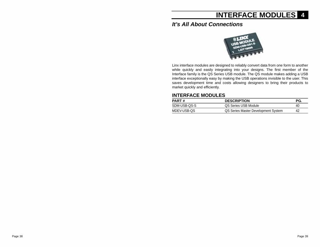
Linx interface modules are designed to reliably convert data from one form to anotherwhile quickly and easily integrating into your designs. The first member of theInterface family is the QS Series USB module. The QS module makes adding a USBinterface exceptionally easy by making the USB operations invisible to the user. Thissaves development time and costs allowing designers to bring their products tomarket quickly and efficiently.
INTERFACE MODULES 4
INTERFACE MODULESPART # DESCRIPTION PG.SDM-USB-QS-S QS Series USB Module 40MDEV-USB-QS QS Series Master Development System 42
It’s All About Connections
Page 41Page 40
WIRELESS MADE SIMPLE ®
Supply Voltage VCC -0.5 to +6.0 VDCAny Input or Output Pin -0.5 to VCC + 0.5 VDCMax Current Sourced By Data Pins 2 mAMax Current Sunk By Data Pins 4 mAOperating Temperature 0 to +70 °CStorage Temperature -65 to +150 °CSoldering Temperature +225°C for 10 seconds
*NOTE* Exceeding any of the limits of this section may lead to permanentdamage to the device. Furthermore, extended operation at these maximumratings may reduce the life of this device.
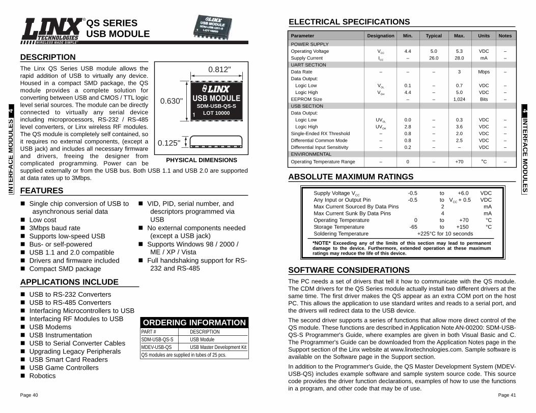
ELECTRICAL SPECIFICATIONSParameter Designation Min. Typical Max. Units Notes
POWER SUPPLYOperating Voltage VCC 4.4 5.0 5.3 VDC –Supply Current ICC – 26.0 28.0 mA –UART SECTIONData Rate – – – 3 Mbps –Data Output:
Logic Low VOL 0.1 – 0.7 VDC –Logic High VOH 4.4 – 5.0 VDC –
EEPROM Size – – 1,024 Bits –USB SECTIONData Output:
Logic Low UVOL 0.0 – 0.3 VDC –Logic High UVOH 2.8 – 3.6 VDC –
Single-Ended RX Threshold – 0.8 – 2.0 VDC –Differential Common Mode – 0.8 – 2.5 VDC –Differential Input Sensitivity – 0.2 – – VDC –ENVIRONMENTALOperating Temperature Range – 0 – +70 °C –
ABSOLUTE MAXIMUM RATINGS
SOFTWARE CONSIDERATIONSThe PC needs a set of drivers that tell it how to communicate with the QS module.The CDM drivers for the QS Series module actually install two different drivers at thesame time. The first driver makes the QS appear as an extra COM port on the hostPC. This allows the application to use standard writes and reads to a serial port, andthe drivers will redirect data to the USB device.The second driver supports a series of functions that allow more direct control of theQS module. These functions are described in Application Note AN-00200: SDM-USB-QS-S Programmer's Guide, where examples are given in both Visual Basic and C.The Programmer's Guide can be downloaded from the Application Notes page in theSupport section of the Linx website at www.linxtechnologies.com. Sample software isavailable on the Software page in the Support section.In addition to the Programmer's Guide, the QS Master Development System (MDEV-USB-QS) includes example software and sample system source code. This sourcecode provides the driver function declarations, examples of how to use the functionsin a program, and other code that may be of use.
INTER
FAC
E MO
DU
LES4
QS SERIESUSB MODULE
DESCRIPTIONThe Linx QS Series USB module allows therapid addition of USB to virtually any device.Housed in a compact SMD package, the QSmodule provides a complete solution forconverting between USB and CMOS / TTL logiclevel serial sources. The module can be directlyconnected to virtually any serial deviceincluding microprocessors, RS-232 / RS-485level converters, or Linx wireless RF modules.The QS module is completely self contained, soit requires no external components, (except aUSB jack) and includes all necessary firmwareand drivers, freeing the designer fromcomplicated programming. Power can besupplied externally or from the USB bus. Both USB 1.1 and USB 2.0 are supportedat data rates up to 3Mbps.
0.125"
0.630"LOT 10000
SDM-USB-QS-SUSB MODULE
0.812"
PHYSICAL DIMENSIONS
USB to RS-232 Converters USB to RS-485 ConvertersInterfacing Microcontrollers to USBInterfacing RF Modules to USBUSB ModemsUSB InstrumentationUSB to Serial Converter CablesUpgrading Legacy PeripheralsUSB Smart Card ReadersUSB Game ControllersRobotics
APPLICATIONS INCLUDE
Single chip conversion of USB toasynchronous serial data
Low cost 3Mbps baud rateSupports low-speed USBBus- or self-poweredUSB 1.1 and 2.0 compatibleDrivers and firmware includedCompact SMD package
VID, PID, serial number, anddescriptors programmed viaUSB
No external components needed(except a USB jack)
Supports Windows 98 / 2000 /ME / XP / Vista
Full handshaking support for RS-232 and RS-485
FEATURES
PART # DESCRIPTIONSDM-USB-QS-S USB ModuleMDEV-USB-QS USB Master Development KitQS modules are supplied in tubes of 25 pcs.
ORDERING INFORMATION
INTE
RFA
CE
MO
DU
LES
4
Page 43Page 42
WIRELESS MADE SIMPLE ®
INTER
FAC
E MO
DU
LES4
FeaturesRS-232 <--> USB InterfaceIntegrated RS-232 Level ConverterOn-Board Demo MicrocontrollerUser Prototyping AreaPre-Assembled for Immediate UseDemonstration Software IncludedSample Source Code Included
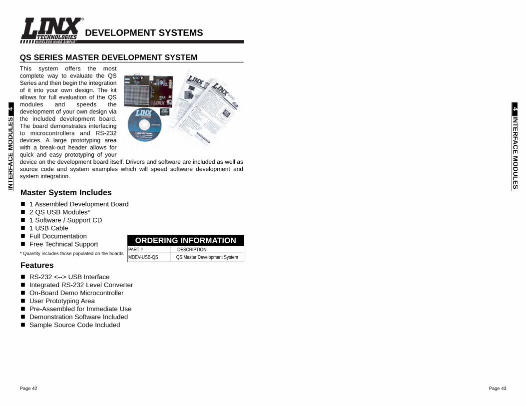
QS SERIES MASTER DEVELOPMENT SYSTEMThis system offers the mostcomplete way to evaluate the QSSeries and then begin the integrationof it into your own design. The kitallows for full evaluation of the QSmodules and speeds thedevelopment of your own design viathe included development board.The board demonstrates interfacingto microcontrollers and RS-232devices. A large prototyping areawith a break-out header allows forquick and easy prototyping of yourdevice on the development board itself. Drivers and software are included as well assource code and system examples which will speed software development andsystem integration.
Master System Includes1 Assembled Development Board2 QS USB Modules*1 Software / Support CD1 USB CableFull DocumentationFree Technical Support
PART # DESCRIPTION MDEV-USB-QS QS Master Development System
ORDERING INFORMATION* Quantity includes those populated on the boards
DEVELOPMENT SYSTEMS
INTE
RFA
CE
MO
DU
LES
4
Page 45Page 44
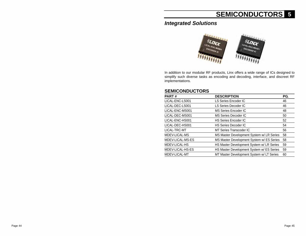
In addition to our modular RF products, Linx offers a wide range of ICs designed tosimplify such diverse tasks as encoding and decoding, interface, and discreet RFimplementations.
SEMICONDUCTORS 5
SEMICONDUCTORSPART # DESCRIPTION PG.LICAL-ENC-LS001 LS Series Encoder IC 46LICAL-DEC-LS001 LS Series Decoder IC 46LICAL-ENC-MS001 MS Series Encoder IC 48LICAL-DEC-MS001 MS Series Decoder IC 50LICAL-ENC-HS001 HS Series Encoder IC 52LICAL-DEC-HS001 HS Series Decoder IC 54LICAL-TRC-MT MT Series Transcoder IC 56MDEV-LICAL-MS MS Master Development System w/ LR Series 58MDEV-LICAL-MS-ES MS Master Development System w/ ES Series 58MDEV-LICAL-HS HS Master Development System w/ LR Series 59MDEV-LICAL-HS-ES HS Master Development System w/ ES Series 59MDEV-LICAL-MT MT Master Development System w/ LT Series 60
Integrated Solutions
Page 47Page 46
WIRELESS MADE SIMPLE ®
ABSOLUTE MAXIMUM RATINGS
Supply Voltage VCC -0.3 to +6.5 VDCAny Input or Output Pin -0.3 to VCC + 0.3 VDCMax. Current Sourced By Data Pins 25 mAMax. Current Sunk By Data Pins 25 mAMax. Current Into VCC 250 mAMax. Current Out Of GND 300 mAOperating Temperature -40 to +125 °CStorage Temperature -65 to +150 °C
*NOTE* Exceeding any of the limits of this section may lead to permanentdamage to the device. Furthermore, extended operation at these maximumratings may reduce the life of this device.
1. Current consumption with no active loads.2. For 3V supply, (0.15 x 3.0) = 0.45V max.3. For 3V supply, (0.8 x 3.0) = 2.4V min.
Notes
SEMIC
ON
DU
CTO
RS
5
ELECTRICAL SPECIFICATIONSParameter Designation Min. Typical Max. Units NotesPOWER SUPPLYOperating Voltage VCC 2.0 – 5.5 VDC –Supply Current: ICC
At 2.0V VCC – 340 450 µA 1At 3.0V VCC – 500 700 µA 1At 5.0V VCC – 800 1,100 µA 1
Power-Down Current: IPDN
At 2.0V VCC – 0.99 700 nAAt 3.0V VCC – 1.2 770 nAAt 5.0V VCC – 2.9 995 nA
ENCODER / DECODER SECTIONInput Low VIL 0.0 – 0.15 x VCC V 2Input High VIH 0.8 x VCC – VCC V 3Output Low VOL – – 0.6 VOutput High VOH VCC - 0.7 – – VInput Sink Current – – – 25 mAOutput Drive Current – – – 25 mAENVIRONMENTALOperating Temperature Range – -40 – +125 °C
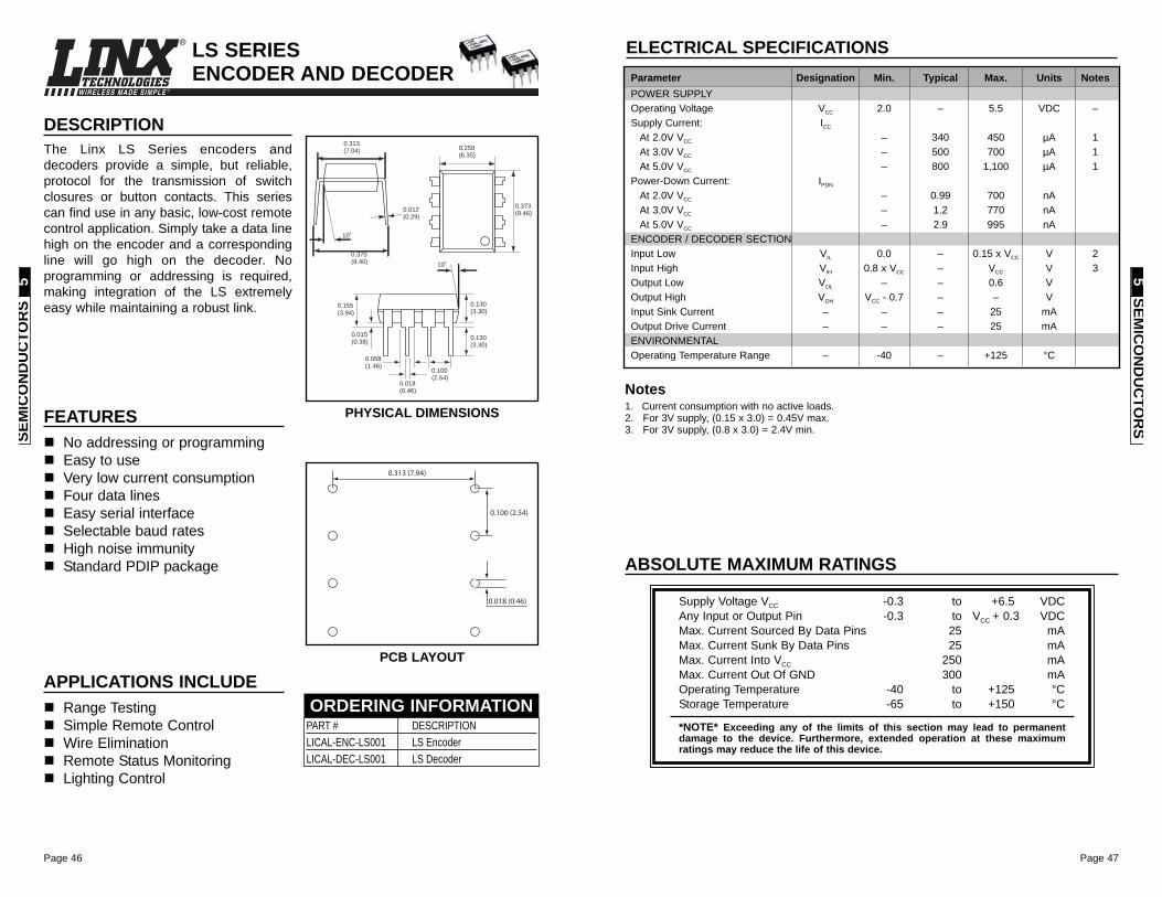
FEATURESNo addressing or programmingEasy to useVery low current consumptionFour data linesEasy serial interfaceSelectable baud ratesHigh noise immunityStandard PDIP package
DESCRIPTIONThe Linx LS Series encoders anddecoders provide a simple, but reliable,protocol for the transmission of switchclosures or button contacts. This seriescan find use in any basic, low-cost remotecontrol application. Simply take a data linehigh on the encoder and a correspondingline will go high on the decoder. Noprogramming or addressing is required,making integration of the LS extremelyeasy while maintaining a robust link.
0.250(6.35)
0.373(9.46)
0.313(7.04)
0.370(9.40)
10˚
0.012(0.29)
0.155(3.94)
0.130(3.30)
0.018(0.46)
0.058(1.46)
0.015(0.38)
0.100 (2.54)
0.130(3.30)
10˚
0.313 (7.94)
0.100 (2.54)
0.018 (0.46)
APPLICATIONS INCLUDERange TestingSimple Remote ControlWire EliminationRemote Status MonitoringLighting Control
LS SERIES ENCODER AND DECODER
PHYSICAL DIMENSIONS
PCB LAYOUT
PART # DESCRIPTIONLICAL-ENC-LS001 LS EncoderLICAL-DEC-LS001 LS Decoder
ORDERING INFORMATION
SEM
ICO
ND
UC
TOR
S5
Page 49Page 48
WIRELESS MADE SIMPLE ®
ELECTRICAL SPECIFICATIONS
ABSOLUTE MAXIMUM RATINGS
Supply Voltage VCC -0.3 to +6.5 VDCAny Input or Output Pin -0.3 to VCC + 0.3 VDCMax. Current Sourced By Output Pins 25 mAMax. Current Sunk By Output Pins 25 mAMax. Current Into VCC 250 mAMax. Current Out Of GND 300 mAOperating Temperature -40 to +125 °CStorage Temperature -65 to +150 °C
*NOTE* Exceeding any of the limits of this section may lead to permanentdamage to the device. Furthermore, extended operation at these maximumratings may reduce the life of this device.
1. Current consumption with no active loads.2. For 3V supply, (0.15 x 3.0) = 0.45V max.3. For 3V supply, (0.8 x 3.0) = 2.4V min.
Notes
Parameter Designation Min. Typical Max. Units NotesPOWER SUPPLYOperating Voltage VCC 2.0 – 5.5 VDC –Supply Current: ICC
At 2.0V VCC – 240 300 µA 1At 3.0V VCC – 370 470 µA 1At 5.0V VCC – 670 780 µA 1
Power-Down Current: IPDN
At 2.0V VCC – 0.10 0.80 µA –At 3.0V VCC – 0.10 0.85 µA –At 5.0V VCC – 0.20 0.95 µA –
ENCODER SECTIONInput Low VIL 0.0 – 0.15 x VCC V 2Input High VIH 0.8 x VCC – VCC V 3Output Low VOL – – 0.6 V –Output High VOH VCC - 0.7 – – V –Input Sink Current – – – 25 mA –Output Drive Current – – – 25 mA –SEND High to DATA_OUT – – 1.64 – mS –ENVIRONMENTALOperating Temperature Range – -40 – +125 °C –
SEMIC
ON
DU
CTO
RS
5
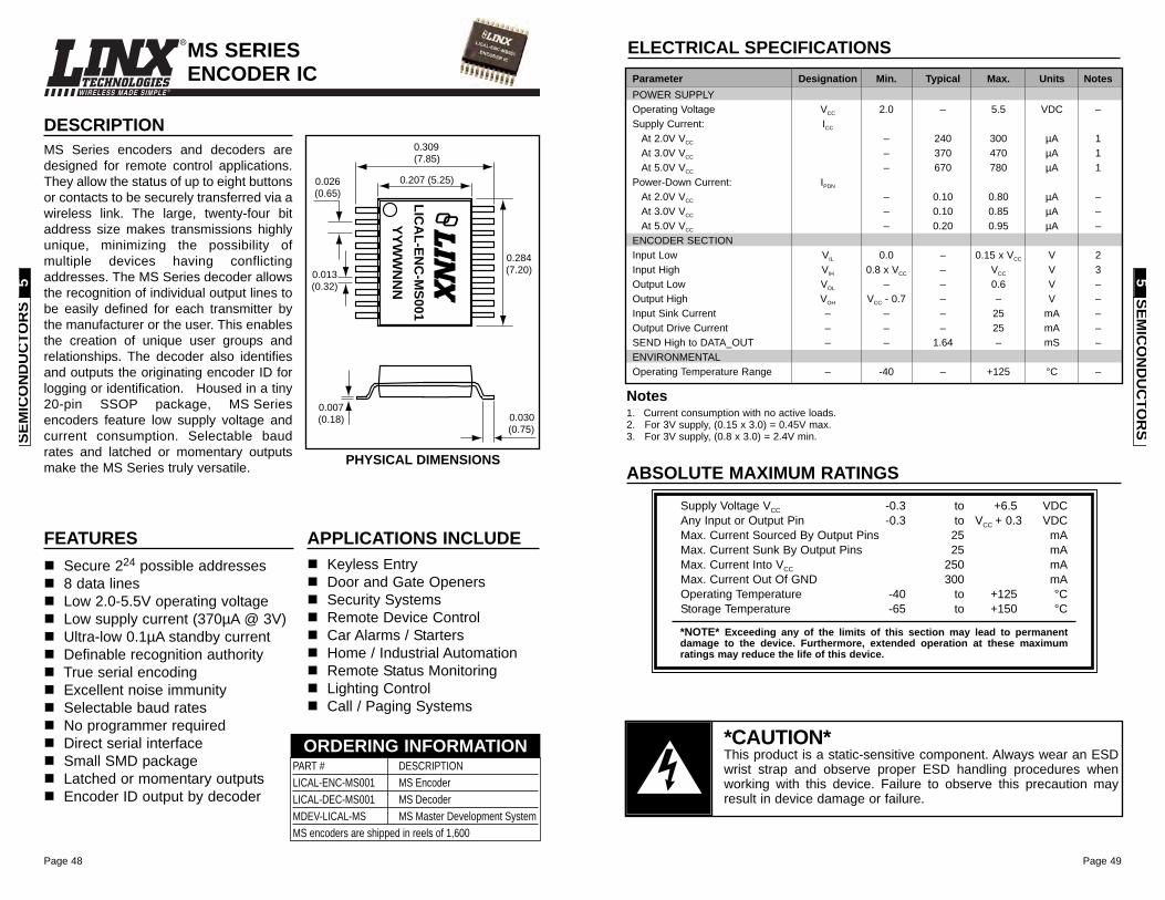
FEATURESSecure 224 possible addresses8 data linesLow 2.0-5.5V operating voltageLow supply current (370µA @ 3V)Ultra-low 0.1µA standby currentDefinable recognition authorityTrue serial encodingExcellent noise immunitySelectable baud ratesNo programmer requiredDirect serial interfaceSmall SMD packageLatched or momentary outputsEncoder ID output by decoder
DESCRIPTIONMS Series encoders and decoders aredesigned for remote control applications.They allow the status of up to eight buttonsor contacts to be securely transferred via awireless link. The large, twenty-four bitaddress size makes transmissions highlyunique, minimizing the possibility ofmultiple devices having conflictingaddresses. The MS Series decoder allowsthe recognition of individual output lines tobe easily defined for each transmitter bythe manufacturer or the user. This enablesthe creation of unique user groups andrelationships. The decoder also identifiesand outputs the originating encoder ID forlogging or identification. Housed in a tiny20-pin SSOP package, MS Seriesencoders feature low supply voltage andcurrent consumption. Selectable baudrates and latched or momentary outputsmake the MS Series truly versatile.
APPLICATIONS INCLUDEKeyless EntryDoor and Gate OpenersSecurity SystemsRemote Device ControlCar Alarms / StartersHome / Industrial AutomationRemote Status MonitoringLighting ControlCall / Paging Systems
0.030(0.75)
0.007(0.18)
0.013(0.32)
0.026(0.65)
0.309(7.85)
0.207 (5.25)
0.284(7.20)
LIC
AL
-EN
C-M
S001
YY
WW
NN
N
MS SERIES ENCODER IC
PHYSICAL DIMENSIONS
PART # DESCRIPTIONLICAL-ENC-MS001 MS EncoderLICAL-DEC-MS001 MS DecoderMDEV-LICAL-MS MS Master Development SystemMS encoders are shipped in reels of 1,600
ORDERING INFORMATION
SEM
ICO
ND
UC
TOR
S5
*CAUTION*This product is a static-sensitive component. Always wear an ESDwrist strap and observe proper ESD handling procedures whenworking with this device. Failure to observe this precaution mayresult in device damage or failure.

Page 51Page 50
WIRELESS MADE SIMPLE ®
ABSOLUTE MAXIMUM RATINGS
Supply Voltage VCC -0.3 to +6.5 VDCAny Input or Output Pin -0.3 to VCC + 0.3 VDCMax. Current Sourced By Output Pins 25 mAMax. Current Sunk By Output Pins 25 mAMax. Current Into VCC 250 mAMax. Current Out Of GND 300 mAOperating Temperature -40 to +125 °CStorage Temperature -65 to +150 °C
*NOTE* Exceeding any of the limits of this section may lead to permanentdamage to the device. Furthermore, extended operation at these maximumratings may reduce the life of this device.
1. Current consumption with no active loads.2. For 3V supply, (0.15 x 3.0) = 0.45V max.3. For 3V supply, (0.8 x 3.0) = 2.4V min.
Notes
ELECTRICAL SPECIFICATIONSParameter Designation Min. Typical Max. Units NotesPOWER SUPPLYOperating Voltage VCC 2.0 – 5.5 VDC –Supply Current: ICC
At 2.0V VCC – 240 300 µA 1At 3.0V VCC – 370 470 µA 1At 5.0V VCC – 670 780 µA 1
Power-Down Current: IPDN
At 2.0V VCC – 0.10 0.80 µA –At 3.0V VCC – 0.10 0.85 µA –At 5.0V VCC – 0.20 0.95 µA –
ENCODER SECTIONInput Low VIL 0.0 – 0.15 x VCC V 2Input High VIH 0.8 x VCC – VCC V 3Output Low VOL – – 0.6 V –Output High VOH VCC - 0.7 – – V –Input Sink Current – – – 25 mA –Output Drive Current – – – 25 mA –SEND High to DATA_OUT – – 1.64 – mS –ENVIRONMENTALOperating Temperature Range – -40 – +125 °C –
SEMIC
ON
DU
CTO
RS
5
WIRELESS MADE SIMPLE ®
FEATURESSecure 224 possible addresses8 data linesDirect serial interfaceLatched or momentary outputsDefinable recognition authorityEncoder ID output by decoder Low 2.0-5.5V operating voltageLow supply current (370µA @ 3V)Ultra-low 0.1µA standby currentTrue serial encodingExcellent noise immunitySelectable baud ratesNo programming requiredSmall SMD package
DESCRIPTIONMS Series encoders and decoders aredesigned for remote control applications.They allow the status of up to eight buttonsor contacts to be securely transferred via awireless link. The large, twenty-four bitaddress size makes transmissions highlyunique, minimizing the possibility ofmultiple devices having conflictingaddresses. The MS Series decoder allowsthe recognition of individual output lines tobe easily defined for each transmitter bythe manufacturer or the user. This enablesthe creation of unique user groups andrelationships. The decoder also identifiesand outputs the originating encoder ID forlogging or identification. Housed in a tiny20-pin SSOP package, MS Series partsfeature low supply voltage and currentconsumption. Selectable baud rates andlatched or momentary outputs make theMS Series truly versatile.
APPLICATIONS INCLUDEKeyless EntryDoor and Gate OpenersSecurity SystemsRemote Device ControlCar Alarms / StartersHome / Industrial AutomationRemote Status MonitoringLighting ControlCall / Paging Systems
0.030(0.75)
0.007(0.18)
0.013(0.32)
0.026(0.65)
0.309(7.85)
0.207 (5.25)
0.284(7.20)
LIC
AL
-DE
C-M
S001
YY
WW
NN
N
MS SERIES DECODER IC
PHYSICAL DIMENSIONS
PART # DESCRIPTIONLICAL-ENC-MS001 MS EncoderLICAL-DEC-MS001 MS DecoderMDEV-LICAL-MS MS Master Development SystemMS decoders are shipped in reels of 1,600
ORDERING INFORMATION
SEM
ICO
ND
UC
TOR
S5
*CAUTION*This product is a static-sensitive component. Always wear an ESDwrist strap and observe proper ESD handling procedures whenworking with this device. Failure to observe this precaution mayresult in device damage or failure.
Page 53Page 52
WIRELESS MADE SIMPLE ®
ABSOLUTE MAXIMUM RATINGS
Supply Voltage VCC -0.3 to +6.5 VDCAny Input or Output Pin -0.3 to VCC + 0.3 VDCMax. Current Sourced By Output Pins 25 mAMax. Current Sunk By Output Pins 25 mAMax. Current Into VCC 250 mAMax. Current Out Of GND 300 mAOperating Temperature -40 to +125 °CStorage Temperature -65 to +150 °C
*NOTE* Exceeding any of the limits of this section may lead to permanentdamage to the device. Furthermore, extended operation at these maximumratings may reduce the life of this device.
1. Current consumption with no active loads.2. For 3V supply, (0.15 x 3.0) = 0.45V max.3. For 3V supply, (0.8 x 3.0) = 2.4V min.
Notes
ELECTRICAL SPECIFICATIONSParameter Designation Min. Typical Max. Units NotesPOWER SUPPLYOperating Voltage VCC 2.0 – 5.5 VDC –Supply Current: ICC
At 2.0V VCC – 240 300 µA 1At 3.0V VCC – 370 470 µA 1At 5.0V VCC – 670 780 µA 1
Power-Down Current: IPDN
At 2.0V VCC – 0.10 0.80 µA –At 3.0V VCC – 0.10 0.85 µA –At 5.0V VCC – 0.20 0.95 µA –
ENCODER SECTIONInput Low VIL 0.0 – 0.15 x VCC V 2Input High VIH 0.8 x VCC – VCC V 3Output Low VOL – – 0.6 V –Output High VOH VCC - 0.7 – – V –Input Sink Current – – – 25 mA –Output Drive Current – – – 25 mA –SEND High to DATA_OUT – – 1.64 – mS –ENVIRONMENTALOperating Temperature Range – -40 – +125 °C –
SEMIC
ON
DU
CTO
RS
5
WIRELESS MADE SIMPLE ®
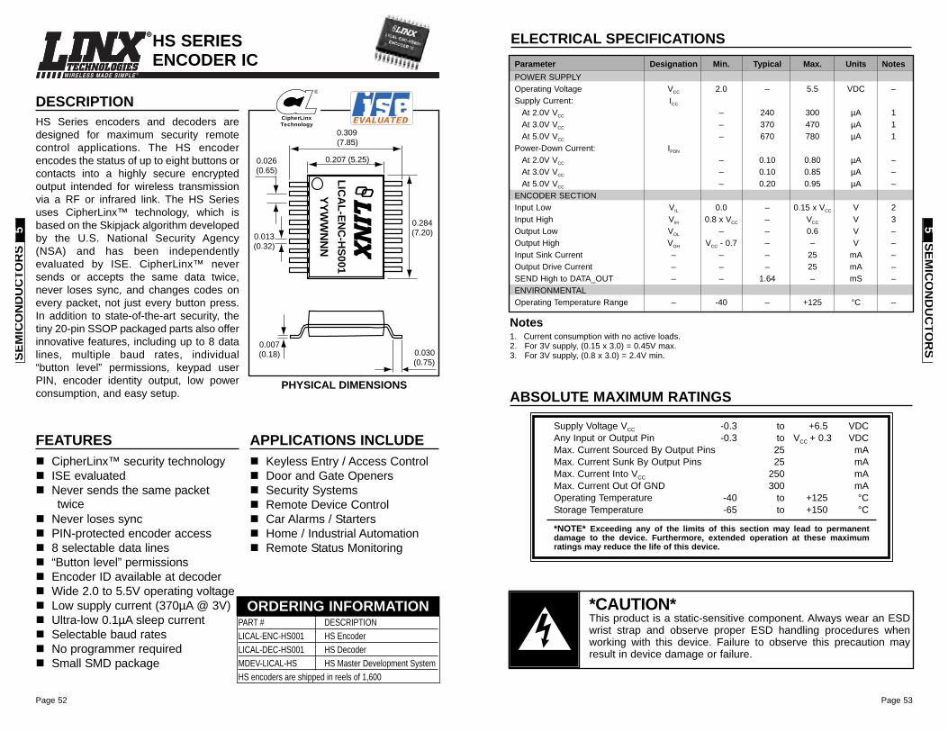
FEATURESCipherLinx™ security technologyISE evaluatedNever sends the same packettwice
Never loses syncPIN-protected encoder access8 selectable data lines“Button level” permissionsEncoder ID available at decoderWide 2.0 to 5.5V operating voltageLow supply current (370µA @ 3V)Ultra-low 0.1µA sleep currentSelectable baud ratesNo programmer requiredSmall SMD package
DESCRIPTIONHS Series encoders and decoders aredesigned for maximum security remotecontrol applications. The HS encoderencodes the status of up to eight buttons orcontacts into a highly secure encryptedoutput intended for wireless transmissionvia a RF or infrared link. The HS Seriesuses CipherLinx™ technology, which isbased on the Skipjack algorithm developedby the U.S. National Security Agency(NSA) and has been independentlyevaluated by ISE. CipherLinx™ neversends or accepts the same data twice,never loses sync, and changes codes onevery packet, not just every button press.In addition to state-of-the-art security, thetiny 20-pin SSOP packaged parts also offerinnovative features, including up to 8 datalines, multiple baud rates, individual“button level” permissions, keypad userPIN, encoder identity output, low powerconsumption, and easy setup.
APPLICATIONS INCLUDEKeyless Entry / Access ControlDoor and Gate OpenersSecurity SystemsRemote Device ControlCar Alarms / StartersHome / Industrial AutomationRemote Status Monitoring
0.030(0.75)
0.007(0.18)
0.013(0.32)
0.026(0.65)
0.309(7.85)
0.207 (5.25)
0.284(7.20)
LIC
AL
-EN
C-H
S001
YY
WW
NN
N
HS SERIES ENCODER IC
PHYSICAL DIMENSIONS
PART # DESCRIPTIONLICAL-ENC-HS001 HS EncoderLICAL-DEC-HS001 HS DecoderMDEV-LICAL-HS HS Master Development SystemHS encoders are shipped in reels of 1,600
ORDERING INFORMATION
EVALUATEDCipherLinx
Technology
®
SEM
ICO
ND
UC
TOR
S5
*CAUTION*This product is a static-sensitive component. Always wear an ESDwrist strap and observe proper ESD handling procedures whenworking with this device. Failure to observe this precaution mayresult in device damage or failure.
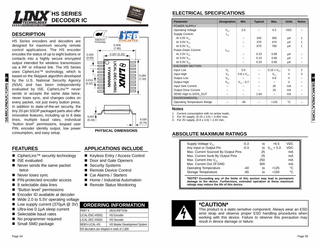
Page 55Page 54
WIRELESS MADE SIMPLE ®
ABSOLUTE MAXIMUM RATINGS
Supply Voltage VCC -0.3 to +6.5 VDCAny Input or Output Pin -0.3 to VCC + 0.3 VDCMax. Current Sourced By Output Pins 25 mAMax. Current Sunk By Output Pins 25 mAMax. Current Into VCC 250 mAMax. Current Out Of GND 300 mAOperating Temperature -40 to +125 °CStorage Temperature -65 to +150 °C
*NOTE* Exceeding any of the limits of this section may lead to permanentdamage to the device. Furthermore, extended operation at these maximumratings may reduce the life of this device.
1. Current consumption with no active loads.2. For 3V supply, (0.15 x 3.0) = 0.45V max.3. For 3V supply, (0.8 x 3.0) = 2.4V min.
Notes
ELECTRICAL SPECIFICATIONSParameter Designation Min. Typical Max. Units NotesPOWER SUPPLYOperating Voltage VCC 2.0 – 5.5 VDC –Supply Current: ICC
At 2.0V VCC – 240 300 µA 1At 3.0V VCC – 370 470 µA 1At 5.0V VCC – 670 780 µA 1
Power-Down Current: IPDN
At 2.0V VCC – 0.10 0.80 µA –At 3.0V VCC – 0.10 0.85 µA –At 5.0V VCC – 0.20 0.95 µA –
ENCODER SECTIONInput Low VIL 0.0 – 0.15 x VCC V 2Input High VIH 0.8 x VCC – VCC V 3Output Low VOL – – 0.6 V –Output High VOH VCC - 0.7 – – V –Input Sink Current – – – 25 mA –Output Drive Current – – – 25 mA –SEND High to DATA_OUT – – 1.64 – mS –ENVIRONMENTALOperating Temperature Range – -40 – +125 °C –
SEMIC
ON
DU
CTO
RS
5
HS SERIES DECODER IC
PART # DESCRIPTIONLICAL-ENC-HS001 HS EncoderLICAL-DEC-HS001 HS DecoderMDEV-LICAL-HS HS Master Development SystemHS decoders are shipped in reels of 1,600
ORDERING INFORMATION
FEATURESCipherLinx™ security technologyISE evaluatedNever sends the same packettwice
Never loses syncPIN-protected encoder access8 selectable data lines“Button level” permissionsEncoder ID available at decoderWide 2.0 to 5.5V operating voltageLow supply current (370µA @ 3V)Ultra-low 0.1µA sleep currentSelectable baud ratesNo programmer requiredSmall SMD package
DESCRIPTIONHS Series encoders and decoders aredesigned for maximum security remotecontrol applications. The HS encoderencodes the status of up to eight buttons orcontacts into a highly secure encryptedoutput intended for wireless transmissionvia a RF or infrared link. The HS Seriesuses CipherLinx™ technology, which isbased on the Skipjack algorithm developedby the U.S. National Security Agency(NSA) and has been independentlyevaluated by ISE. CipherLinx™ neversends or accepts the same data twice,never loses sync, and changes codes onevery packet, not just every button press.In addition to state-of-the-art security, thetiny 20-pin SSOP packaged parts also offerinnovative features, including up to 8 datalines, multiple baud rates, individual“button level” permissions, keypad userPIN, encoder identity output, low powerconsumption, and easy setup.
APPLICATIONS INCLUDEKeyless Entry / Access ControlDoor and Gate OpenersSecurity SystemsRemote Device ControlCar Alarms / StartersHome / Industrial AutomationRemote Status Monitoring
0.030(0.75)
0.007(0.18)
0.013(0.32)
0.026(0.65)
0.309(7.85)
0.207 (5.25)
0.284(7.20)
LIC
AL
-DE
C-H
S001
YY
WW
NN
N
PHYSICAL DIMENSIONS
EVALUATEDCipherLinx
Technology
®
SEM
ICO
ND
UC
TOR
S5
*CAUTION*This product is a static-sensitive component. Always wear an ESDwrist strap and observe proper ESD handling procedures whenworking with this device. Failure to observe this precaution mayresult in device damage or failure.
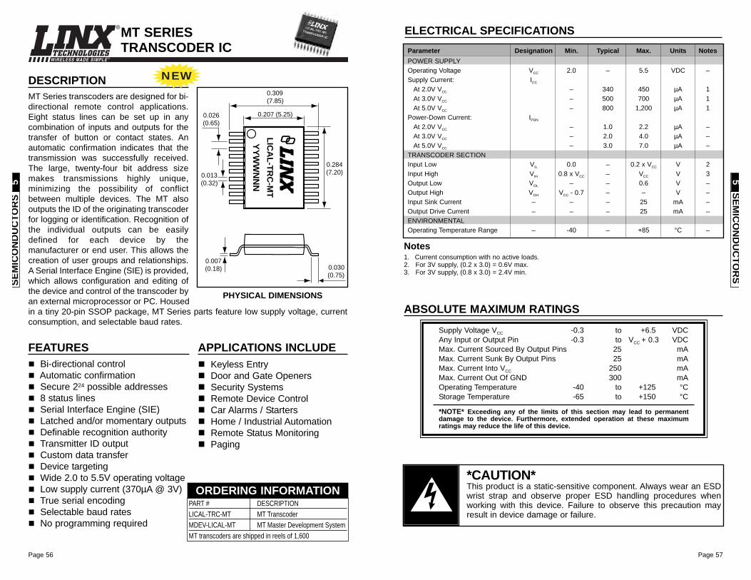
Page 56
WIRELESS MADE SIMPLE ®
Page 57
SEM
ICO
ND
UC
TOR
S5
SEMIC
ON
DU
CTO
RS
5
MT SERIES TRANSCODER IC
FEATURESBi-directional controlAutomatic confirmationSecure 224 possible addresses8 status linesSerial Interface Engine (SIE)Latched and/or momentary outputsDefinable recognition authorityTransmitter ID outputCustom data transferDevice targetingWide 2.0 to 5.5V operating voltageLow supply current (370µA @ 3V)True serial encodingSelectable baud ratesNo programming required
DESCRIPTIONMT Series transcoders are designed for bi-directional remote control applications.Eight status lines can be set up in anycombination of inputs and outputs for thetransfer of button or contact states. Anautomatic confirmation indicates that thetransmission was successfully received.The large, twenty-four bit address sizemakes transmissions highly unique,minimizing the possibility of conflictbetween multiple devices. The MT alsooutputs the ID of the originating transcoderfor logging or identification. Recognition ofthe individual outputs can be easilydefined for each device by themanufacturer or end user. This allows thecreation of user groups and relationships.A Serial Interface Engine (SIE) is provided,which allows configuration and editing ofthe device and control of the transcoder byan external microprocessor or PC. Housedin a tiny 20-pin SSOP package, MT Series parts feature low supply voltage, currentconsumption, and selectable baud rates.
APPLICATIONS INCLUDEKeyless EntryDoor and Gate OpenersSecurity SystemsRemote Device ControlCar Alarms / StartersHome / Industrial AutomationRemote Status MonitoringPaging
0.030(0.75)
0.007(0.18)
0.013(0.32)
0.026(0.65)
0.309(7.85)
0.207 (5.25)
0.284(7.20)
LIC
AL
-TR
C-M
T
YY
WW
NN
NPART # DESCRIPTIONLICAL-TRC-MT MT TranscoderMDEV-LICAL-MT MT Master Development SystemMT transcoders are shipped in reels of 1,600
ORDERING INFORMATION
PHYSICAL DIMENSIONSABSOLUTE MAXIMUM RATINGS
Supply Voltage VCC -0.3 to +6.5 VDCAny Input or Output Pin -0.3 to VCC + 0.3 VDCMax. Current Sourced By Output Pins 25 mAMax. Current Sunk By Output Pins 25 mAMax. Current Into VCC 250 mAMax. Current Out Of GND 300 mAOperating Temperature -40 to +125 °CStorage Temperature -65 to +150 °C
*NOTE* Exceeding any of the limits of this section may lead to permanentdamage to the device. Furthermore, extended operation at these maximumratings may reduce the life of this device.
1. Current consumption with no active loads.2. For 3V supply, (0.2 x 3.0) = 0.6V max.3. For 3V supply, (0.8 x 3.0) = 2.4V min.
Notes
ELECTRICAL SPECIFICATIONSParameter Designation Min. Typical Max. Units NotesPOWER SUPPLYOperating Voltage VCC 2.0 – 5.5 VDC –Supply Current: ICC
At 2.0V VCC – 340 450 µA 1At 3.0V VCC – 500 700 µA 1At 5.0V VCC – 800 1,200 µA 1
Power-Down Current: IPDN
At 2.0V VCC – 1.0 2.2 µA –At 3.0V VCC – 2.0 4.0 µA –At 5.0V VCC – 3.0 7.0 µA –
TRANSCODER SECTIONInput Low VIL 0.0 – 0.2 x VCC V 2Input High VIH 0.8 x VCC – VCC V 3Output Low VOL – – 0.6 V –Output High VOH VCC - 0.7 – – V –Input Sink Current – – – 25 mA –Output Drive Current – – – 25 mA –ENVIRONMENTALOperating Temperature Range – -40 – +85 °C –
*CAUTION*This product is a static-sensitive component. Always wear an ESDwrist strap and observe proper ESD handling procedures whenworking with this device. Failure to observe this precaution mayresult in device damage or failure.
NEW
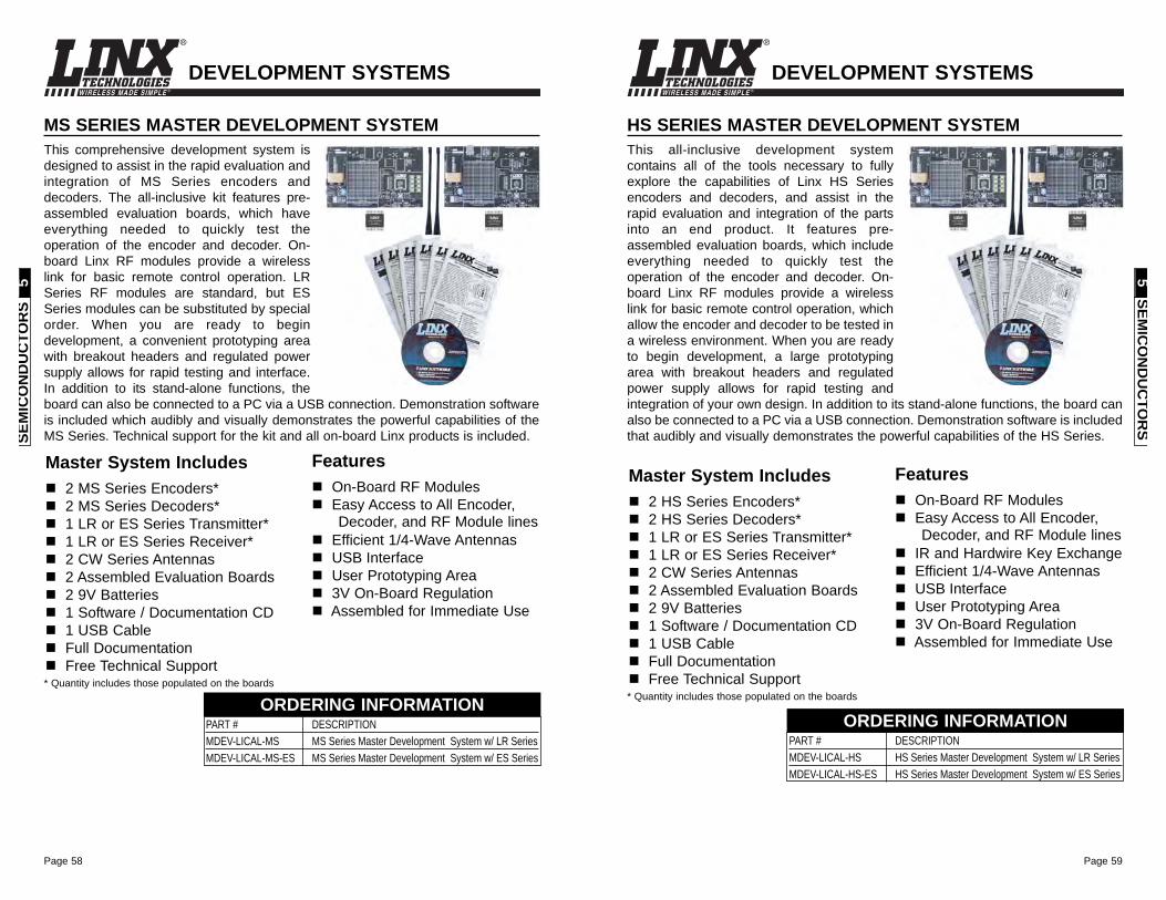
Page 59
WIRELESS MADE SIMPLE ®
Page 58
WIRELESS MADE SIMPLE ®
DEVELOPMENT SYSTEMS
HS SERIES MASTER DEVELOPMENT SYSTEMThis all-inclusive development systemcontains all of the tools necessary to fullyexplore the capabilities of Linx HS Seriesencoders and decoders, and assist in therapid evaluation and integration of the partsinto an end product. It features pre-assembled evaluation boards, which includeeverything needed to quickly test theoperation of the encoder and decoder. On-board Linx RF modules provide a wirelesslink for basic remote control operation, whichallow the encoder and decoder to be tested ina wireless environment. When you are readyto begin development, a large prototypingarea with breakout headers and regulatedpower supply allows for rapid testing andintegration of your own design. In addition to its stand-alone functions, the board canalso be connected to a PC via a USB connection. Demonstration software is includedthat audibly and visually demonstrates the powerful capabilities of the HS Series.
PART # DESCRIPTION MDEV-LICAL-HS HS Series Master Development System w/ LR SeriesMDEV-LICAL-HS-ES HS Series Master Development System w/ ES Series
ORDERING INFORMATION
Master System Includes2 HS Series Encoders*2 HS Series Decoders*1 LR or ES Series Transmitter*1 LR or ES Series Receiver*2 CW Series Antennas2 Assembled Evaluation Boards2 9V Batteries1 Software / Documentation CD1 USB CableFull DocumentationFree Technical Support
* Quantity includes those populated on the boards
FeaturesOn-Board RF ModulesEasy Access to All Encoder,Decoder, and RF Module lines
IR and Hardwire Key ExchangeEfficient 1/4-Wave AntennasUSB InterfaceUser Prototyping Area3V On-Board RegulationAssembled for Immediate Use
SEMIC
ON
DU
CTO
RS
5
DEVELOPMENT SYSTEMS
MS SERIES MASTER DEVELOPMENT SYSTEMThis comprehensive development system isdesigned to assist in the rapid evaluation andintegration of MS Series encoders anddecoders. The all-inclusive kit features pre-assembled evaluation boards, which haveeverything needed to quickly test theoperation of the encoder and decoder. On-board Linx RF modules provide a wirelesslink for basic remote control operation. LRSeries RF modules are standard, but ESSeries modules can be substituted by specialorder. When you are ready to begindevelopment, a convenient prototyping areawith breakout headers and regulated powersupply allows for rapid testing and interface.In addition to its stand-alone functions, theboard can also be connected to a PC via a USB connection. Demonstration softwareis included which audibly and visually demonstrates the powerful capabilities of theMS Series. Technical support for the kit and all on-board Linx products is included.
PART # DESCRIPTION MDEV-LICAL-MS MS Series Master Development System w/ LR SeriesMDEV-LICAL-MS-ES MS Series Master Development System w/ ES Series
ORDERING INFORMATION
Master System Includes2 MS Series Encoders*2 MS Series Decoders*1 LR or ES Series Transmitter*1 LR or ES Series Receiver*2 CW Series Antennas2 Assembled Evaluation Boards2 9V Batteries1 Software / Documentation CD1 USB CableFull DocumentationFree Technical Support
* Quantity includes those populated on the boards
FeaturesOn-Board RF ModulesEasy Access to All Encoder,Decoder, and RF Module lines
Efficient 1/4-Wave AntennasUSB InterfaceUser Prototyping Area3V On-Board RegulationAssembled for Immediate Use
SEM
ICO
ND
UC
TOR
S5
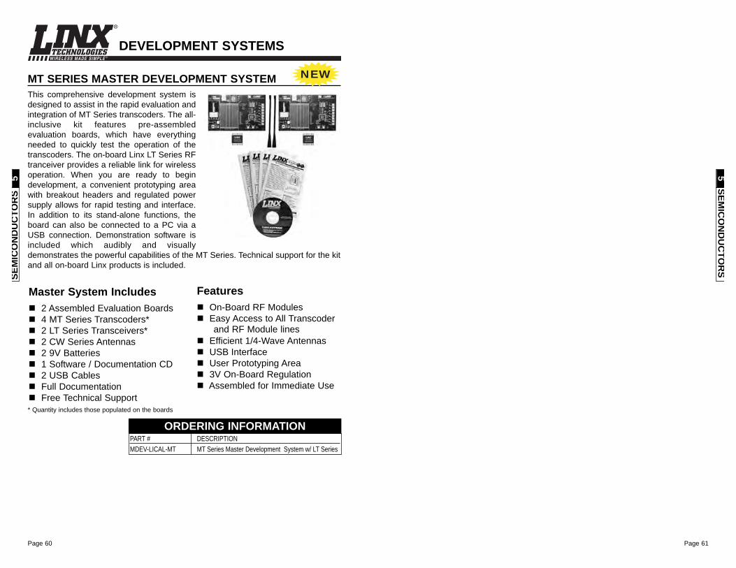
Page 60
WIRELESS MADE SIMPLE ®
Page 61
DEVELOPMENT SYSTEMS
MT SERIES MASTER DEVELOPMENT SYSTEMThis comprehensive development system isdesigned to assist in the rapid evaluation andintegration of MT Series transcoders. The all-inclusive kit features pre-assembledevaluation boards, which have everythingneeded to quickly test the operation of thetranscoders. The on-board Linx LT Series RFtranceiver provides a reliable link for wirelessoperation. When you are ready to begindevelopment, a convenient prototyping areawith breakout headers and regulated powersupply allows for rapid testing and interface.In addition to its stand-alone functions, theboard can also be connected to a PC via aUSB connection. Demonstration software isincluded which audibly and visuallydemonstrates the powerful capabilities of the MT Series. Technical support for the kitand all on-board Linx products is included.
PART # DESCRIPTION MDEV-LICAL-MT MT Series Master Development System w/ LT Series
ORDERING INFORMATION
Master System Includes2 Assembled Evaluation Boards4 MT Series Transcoders*2 LT Series Transceivers*2 CW Series Antennas2 9V Batteries1 Software / Documentation CD2 USB CablesFull DocumentationFree Technical Support
* Quantity includes those populated on the boards
FeaturesOn-Board RF ModulesEasy Access to All Transcoderand RF Module lines
Efficient 1/4-Wave AntennasUSB InterfaceUser Prototyping Area3V On-Board RegulationAssembled for Immediate Use
SEM
ICO
ND
UC
TOR
S5
SEMIC
ON
DU
CTO
RS
5
NEW
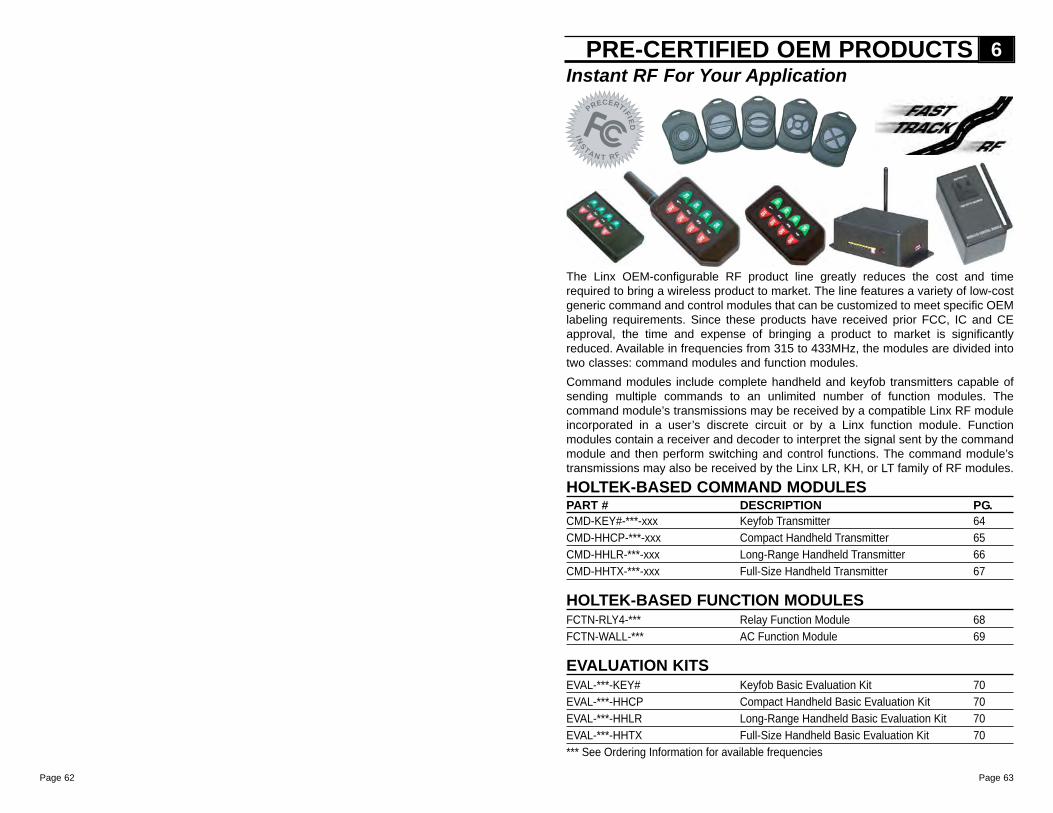
Page 63Page 62
IN
S
TA
NT RF
PRECERT
IFIE
D
Instant RF For Your Application
The Linx OEM-configurable RF product line greatly reduces the cost and timerequired to bring a wireless product to market. The line features a variety of low-costgeneric command and control modules that can be customized to meet specific OEMlabeling requirements. Since these products have received prior FCC, IC and CEapproval, the time and expense of bringing a product to market is significantlyreduced. Available in frequencies from 315 to 433MHz, the modules are divided intotwo classes: command modules and function modules.Command modules include complete handheld and keyfob transmitters capable ofsending multiple commands to an unlimited number of function modules. Thecommand module’s transmissions may be received by a compatible Linx RF moduleincorporated in a user’s discrete circuit or by a Linx function module. Functionmodules contain a receiver and decoder to interpret the signal sent by the commandmodule and then perform switching and control functions. The command module’stransmissions may also be received by the Linx LR, KH, or LT family of RF modules.
HOLTEK-BASED COMMAND MODULESPART # DESCRIPTION PG.CMD-KEY#-***-xxx Keyfob Transmitter 64CMD-HHCP-***-xxx Compact Handheld Transmitter 65CMD-HHLR-***-xxx Long-Range Handheld Transmitter 66CMD-HHTX-***-xxx Full-Size Handheld Transmitter 67
HOLTEK-BASED FUNCTION MODULESFCTN-RLY4-*** Relay Function Module 68FCTN-WALL-*** AC Function Module 69
EVALUATION KITSEVAL-***-KEY# Keyfob Basic Evaluation Kit 70EVAL-***-HHCP Compact Handheld Basic Evaluation Kit 70EVAL-***-HHLR Long-Range Handheld Basic Evaluation Kit 70EVAL-***-HHTX Full-Size Handheld Basic Evaluation Kit 70*** See Ordering Information for available frequencies
PRE-CERTIFIED OEM PRODUCTS 6
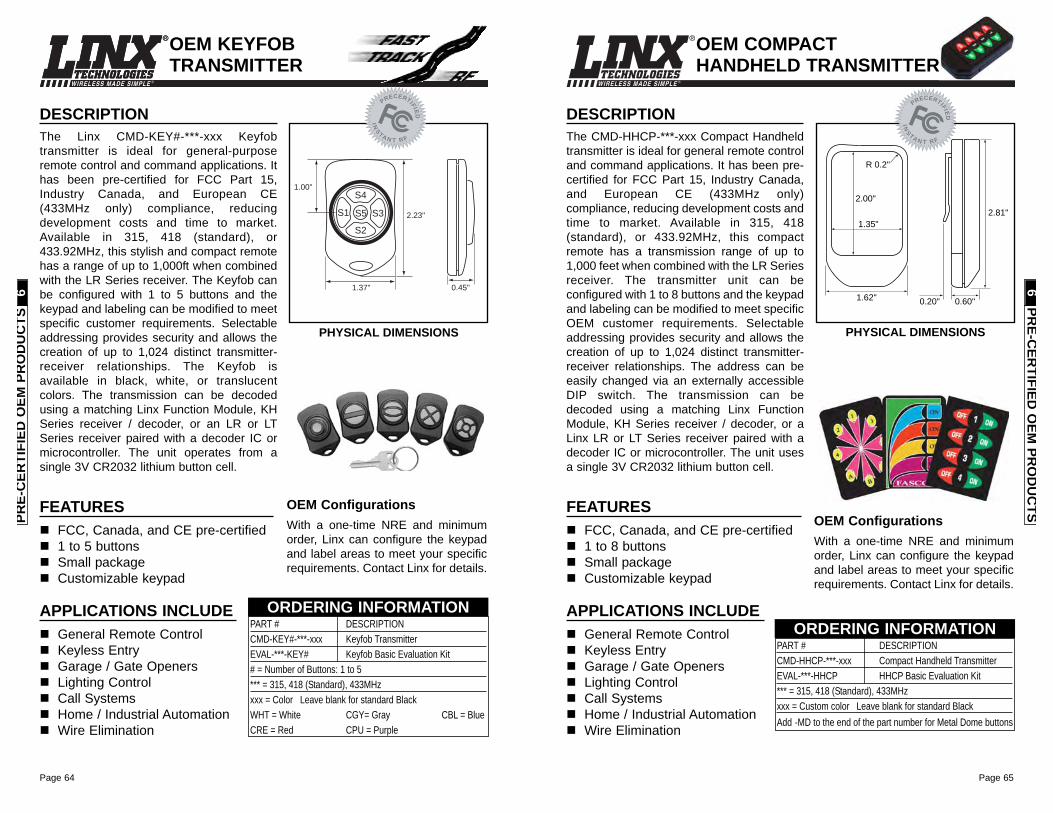
Page 65
WIRELESS MADE SIMPLE ®
Page 64
WIRELESS MADE SIMPLE ®
DESCRIPTIONThe CMD-HHCP-***-xxx Compact Handheldtransmitter is ideal for general remote controland command applications. It has been pre-certified for FCC Part 15, Industry Canada,and European CE (433MHz only)compliance, reducing development costs andtime to market. Available in 315, 418(standard), or 433.92MHz, this compactremote has a transmission range of up to1,000 feet when combined with the LR Seriesreceiver. The transmitter unit can beconfigured with 1 to 8 buttons and the keypadand labeling can be modified to meet specificOEM customer requirements. Selectableaddressing provides security and allows thecreation of up to 1,024 distinct transmitter-receiver relationships. The address can beeasily changed via an externally accessibleDIP switch. The transmission can bedecoded using a matching Linx FunctionModule, KH Series receiver / decoder, or aLinx LR or LT Series receiver paired with adecoder IC or microcontroller. The unit usesa single 3V CR2032 lithium button cell.
FEATURESFCC, Canada, and CE pre-certified 1 to 8 buttonsSmall packageCustomizable keypad
APPLICATIONS INCLUDEGeneral Remote Control Keyless EntryGarage / Gate OpenersLighting ControlCall SystemsHome / Industrial AutomationWire Elimination
OEM ConfigurationsWith a one-time NRE and minimumorder, Linx can configure the keypadand label areas to meet your specificrequirements. Contact Linx for details.
2.00"
1.35"
R 0.2"
2.81"
1.62" 0.60"0.20"
OEM COMPACTHANDHELD TRANSMITTER
PHYSICAL DIMENSIONS
IN
S
TA
NT RF
PRECERT
IFIE
D
PRE-C
ERTIFIED
OEM
PRO
DU
CTS
6
PART # DESCRIPTIONCMD-HHCP-***-xxx Compact Handheld TransmitterEVAL-***-HHCP HHCP Basic Evaluation Kit*** = 315, 418 (Standard), 433MHzxxx = Custom color Leave blank for standard BlackAdd -MD to the end of the part number for Metal Dome buttons
ORDERING INFORMATION
WIRELESS MADE SIMPLE ®
DESCRIPTIONThe Linx CMD-KEY#-***-xxx Keyfobtransmitter is ideal for general-purposeremote control and command applications. Ithas been pre-certified for FCC Part 15,Industry Canada, and European CE(433MHz only) compliance, reducingdevelopment costs and time to market.Available in 315, 418 (standard), or433.92MHz, this stylish and compact remotehas a range of up to 1,000ft when combinedwith the LR Series receiver. The Keyfob canbe configured with 1 to 5 buttons and thekeypad and labeling can be modified to meetspecific customer requirements. Selectableaddressing provides security and allows thecreation of up to 1,024 distinct transmitter-receiver relationships. The Keyfob isavailable in black, white, or translucentcolors. The transmission can be decodedusing a matching Linx Function Module, KHSeries receiver / decoder, or an LR or LTSeries receiver paired with a decoder IC ormicrocontroller. The unit operates from asingle 3V CR2032 lithium button cell.
FEATURESFCC, Canada, and CE pre-certified 1 to 5 buttonsSmall packageCustomizable keypad
APPLICATIONS INCLUDEGeneral Remote Control Keyless EntryGarage / Gate OpenersLighting ControlCall SystemsHome / Industrial AutomationWire Elimination
OEM ConfigurationsWith a one-time NRE and minimumorder, Linx can configure the keypadand label areas to meet your specificrequirements. Contact Linx for details.
2.23"
1.00"
0.45"1.37"
S4
S2
S1 S3S5
PART # DESCRIPTIONCMD-KEY#-***-xxx Keyfob TransmitterEVAL-***-KEY# Keyfob Basic Evaluation Kit# = Number of Buttons: 1 to 5*** = 315, 418 (Standard), 433MHzxxx = Color Leave blank for standard BlackWHT = White CGY= Gray CBL = BlueCRE = Red CPU = Purple
ORDERING INFORMATION
PHYSICAL DIMENSIONS
OEM KEYFOBTRANSMITTER
IN
S
TA
NT RF
PRECERT
IFIE
D
PRE-
CER
TIFI
ED O
EM P
RO
DU
CTS
6
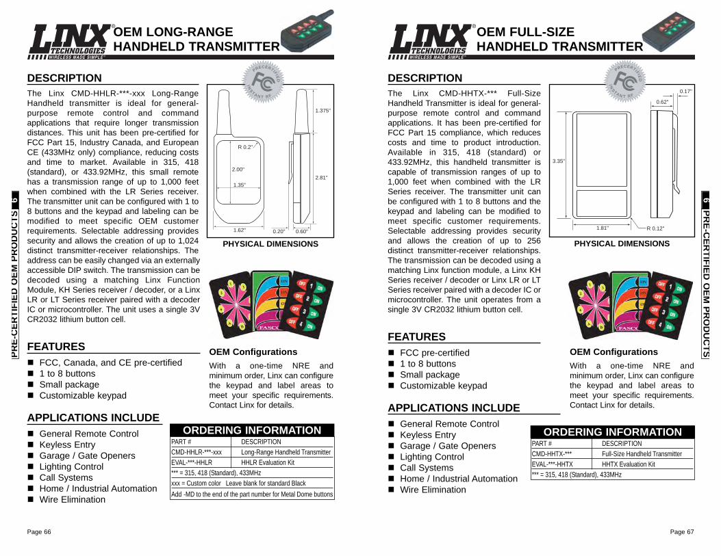
Page 67
WIRELESS MADE SIMPLE ®
Page 66
WIRELESS MADE SIMPLE ®
OEM FULL-SIZEHANDHELD TRANSMITTER
DESCRIPTIONThe Linx CMD-HHTX-*** Full-SizeHandheld Transmitter is ideal for general-purpose remote control and commandapplications. It has been pre-certified forFCC Part 15 compliance, which reducescosts and time to product introduction.Available in 315, 418 (standard) or433.92MHz, this handheld transmitter iscapable of transmission ranges of up to1,000 feet when combined with the LRSeries receiver. The transmitter unit canbe configured with 1 to 8 buttons and thekeypad and labeling can be modified tomeet specific customer requirements.Selectable addressing provides securityand allows the creation of up to 256distinct transmitter-receiver relationships.The transmission can be decoded using amatching Linx function module, a Linx KHSeries receiver / decoder or Linx LR or LTSeries receiver paired with a decoder IC ormicrocontroller. The unit operates from asingle 3V CR2032 lithium button cell.
FEATURESFCC pre-certified 1 to 8 buttonsSmall packageCustomizable keypad
APPLICATIONS INCLUDEGeneral Remote Control Keyless EntryGarage / Gate OpenersLighting ControlCall SystemsHome / Industrial AutomationWire Elimination
OEM ConfigurationsWith a one-time NRE andminimum order, Linx can configurethe keypad and label areas tomeet your specific requirements.Contact Linx for details.
0.17"
0.62"
R 0.12"
3.35"
1.81"
PART # DESCRIPTIONCMD-HHTX-*** Full-Size Handheld TransmitterEVAL-***-HHTX HHTX Evaluation Kit*** = 315, 418 (Standard), 433MHz
ORDERING INFORMATION
PHYSICAL DIMENSIONS
IN
S
TA
NT RF
PRECERT
IFIE
D
PRE-C
ERTIFIED
OEM
PRO
DU
CTS
6
DESCRIPTIONThe Linx CMD-HHLR-***-xxx Long-RangeHandheld transmitter is ideal for general-purpose remote control and commandapplications that require longer transmissiondistances. This unit has been pre-certified forFCC Part 15, Industry Canada, and EuropeanCE (433MHz only) compliance, reducing costsand time to market. Available in 315, 418(standard), or 433.92MHz, this small remotehas a transmission range of up to 1,000 feetwhen combined with the LR Series receiver.The transmitter unit can be configured with 1 to8 buttons and the keypad and labeling can bemodified to meet specific OEM customerrequirements. Selectable addressing providessecurity and allows the creation of up to 1,024distinct transmitter-receiver relationships. Theaddress can be easily changed via an externallyaccessible DIP switch. The transmission can bedecoded using a matching Linx FunctionModule, KH Series receiver / decoder, or a LinxLR or LT Series receiver paired with a decoderIC or microcontroller. The unit uses a single 3VCR2032 lithium button cell.
FEATURESFCC, Canada, and CE pre-certified 1 to 8 buttonsSmall packageCustomizable keypad
APPLICATIONS INCLUDEGeneral Remote Control Keyless EntryGarage / Gate OpenersLighting ControlCall SystemsHome / Industrial AutomationWire Elimination
OEM ConfigurationsWith a one-time NRE andminimum order, Linx can configurethe keypad and label areas tomeet your specific requirements.Contact Linx for details.
0.60"0.20"
1.375"
2.81"
1.62"
2.00"
1.35"
R 0.2"
OEM LONG-RANGEHANDHELD TRANSMITTER
PHYSICAL DIMENSIONS
IN
S
TA
NT RF
PRECERT
IFIE
DPART # DESCRIPTIONCMD-HHLR-***-xxx Long-Range Handheld TransmitterEVAL-***-HHLR HHLR Evaluation Kit*** = 315, 418 (Standard), 433MHzxxx = Custom color Leave blank for standard BlackAdd -MD to the end of the part number for Metal Dome buttons
ORDERING INFORMATION
PRE-
CER
TIFI
ED O
EM P
RO
DU
CTS
6
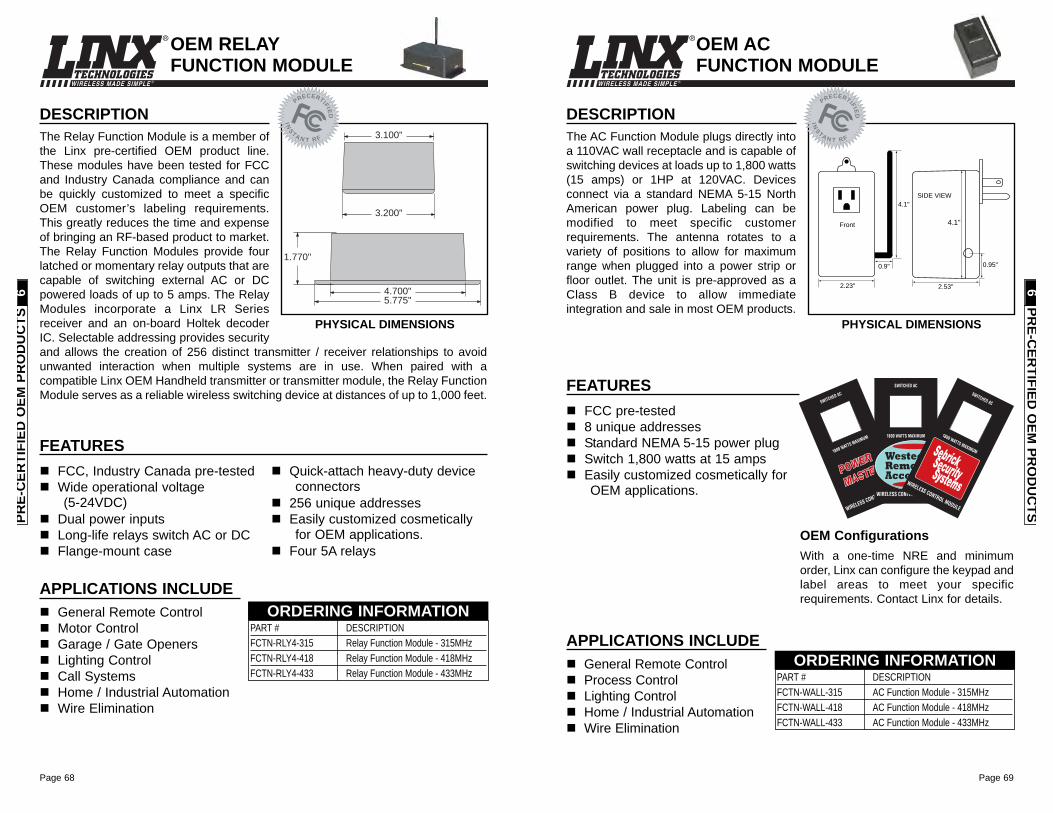
Page 69
WIRELESS MADE SIMPLE ®
Page 68
WIRELESS MADE SIMPLE ®
OEM AC FUNCTION MODULE
DESCRIPTIONThe AC Function Module plugs directly intoa 110VAC wall receptacle and is capable ofswitching devices at loads up to 1,800 watts(15 amps) or 1HP at 120VAC. Devicesconnect via a standard NEMA 5-15 NorthAmerican power plug. Labeling can bemodified to meet specific customerrequirements. The antenna rotates to avariety of positions to allow for maximumrange when plugged into a power strip orfloor outlet. The unit is pre-approved as aClass B device to allow immediateintegration and sale in most OEM products.
2.23"
Front
SIDE VIEW
0.95"
4.1"
SIDE VIEW
2.53"
4.1"
0.9"
APPLICATIONS INCLUDEGeneral Remote Control Process ControlLighting ControlHome / Industrial AutomationWire Elimination
PART # DESCRIPTIONFCTN-WALL-315 AC Function Module - 315MHzFCTN-WALL-418 AC Function Module - 418MHzFCTN-WALL-433 AC Function Module - 433MHz
ORDERING INFORMATION
FCC pre-tested 8 unique addressesStandard NEMA 5-15 power plugSwitch 1,800 watts at 15 ampsEasily customized cosmetically forOEM applications.
FEATURES
PHYSICAL DIMENSIONS
IN
S
TA
NT RF
PRECERT
IFIE
D
OEM ConfigurationsWith a one-time NRE and minimumorder, Linx can configure the keypad andlabel areas to meet your specificrequirements. Contact Linx for details.
PRE-C
ERTIFIED
OEM
PRO
DU
CTS
6
DESCRIPTIONThe Relay Function Module is a member ofthe Linx pre-certified OEM product line.These modules have been tested for FCCand Industry Canada compliance and canbe quickly customized to meet a specificOEM customer’s labeling requirements.This greatly reduces the time and expenseof bringing an RF-based product to market.The Relay Function Modules provide fourlatched or momentary relay outputs that arecapable of switching external AC or DCpowered loads of up to 5 amps. The RelayModules incorporate a Linx LR Seriesreceiver and an on-board Holtek decoderIC. Selectable addressing provides securityand allows the creation of 256 distinct transmitter / receiver relationships to avoidunwanted interaction when multiple systems are in use. When paired with acompatible Linx OEM Handheld transmitter or transmitter module, the Relay FunctionModule serves as a reliable wireless switching device at distances of up to 1,000 feet.
1.770"
4.700"5.775"
3.100"
3.200"
APPLICATIONS INCLUDEGeneral Remote Control Motor ControlGarage / Gate OpenersLighting ControlCall SystemsHome / Industrial AutomationWire Elimination
PART # DESCRIPTIONFCTN-RLY4-315 Relay Function Module - 315MHzFCTN-RLY4-418 Relay Function Module - 418MHzFCTN-RLY4-433 Relay Function Module - 433MHz
ORDERING INFORMATION
FCC, Industry Canada pre-tested Wide operational voltage(5-24VDC)
Dual power inputsLong-life relays switch AC or DCFlange-mount case
Quick-attach heavy-duty deviceconnectors
256 unique addressesEasily customized cosmeticallyfor OEM applications.
Four 5A relays
FEATURES
OEM RELAYFUNCTION MODULE
PHYSICAL DIMENSIONS
IN
S
TA
NT RF
PRECERT
IFIE
D
PRE-
CER
TIFI
ED O
EM P
RO
DU
CTS
6
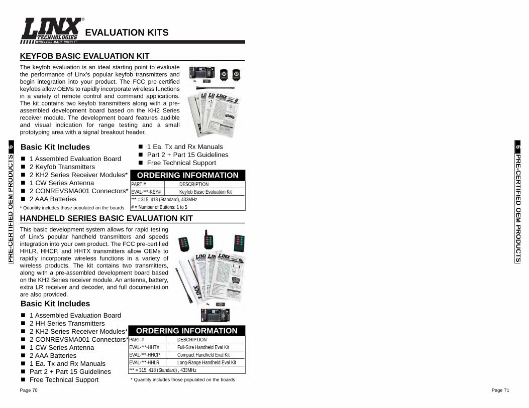
Page 71Page 70
WIRELESS MADE SIMPLE ®
PRE-C
ERTIFIED
OEM
PRO
DU
CTS
6
HANDHELD SERIES BASIC EVALUATION KITThis basic development system allows for rapid testingof Linx’s popular handheld transmitters and speedsintegration into your own product. The FCC pre-certifiedHHLR, HHCP, and HHTX transmitters allow OEMs torapidly incorporate wireless functions in a variety ofwireless products. The kit contains two transmitters,along with a pre-assembled development board basedon the KH2 Series receiver module. An antenna, battery,extra LR receiver and decoder, and full documentationare also provided.
PART # DESCRIPTIONEVAL-***-HHTX Full-Size Handheld Eval KitEVAL-***-HHCP Compact Handheld Eval KitEVAL-***-HHLR Long-Range Handheld Eval Kit*** = 315, 418 (Standard) , 433MHz
ORDERING INFORMATION
KEYFOB BASIC EVALUATION KITThe keyfob evaluation is an ideal starting point to evaluatethe performance of Linx’s popular keyfob transmitters andbegin integration into your product. The FCC pre-certifiedkeyfobs allow OEMs to rapidly incorporate wireless functionsin a variety of remote control and command applications.The kit contains two keyfob transmitters along with a pre-assembled development board based on the KH2 Seriesreceiver module. The development board features audibleand visual indication for range testing and a smallprototyping area with a signal breakout header.
Basic Kit Includes1 Assembled Evaluation Board2 Keyfob Transmitters2 KH2 Series Receiver Modules*1 CW Series Antenna2 CONREVSMA001 Connectors*2 AAA Batteries
1 Ea. Tx and Rx ManualsPart 2 + Part 15 GuidelinesFree Technical Support
PART # DESCRIPTION EVAL-***-KEY# Keyfob Basic Evaluation Kit*** = 315, 418 (Standard), 433MHz# = Number of Buttons: 1 to 5
ORDERING INFORMATION
Basic Kit Includes1 Assembled Evaluation Board2 HH Series Transmitters2 KH2 Series Receiver Modules*2 CONREVSMA001 Connectors*1 CW Series Antenna2 AAA Batteries1 Ea. Tx and Rx ManualsPart 2 + Part 15 GuidelinesFree Technical Support
* Quantity includes those populated on the boards
* Quantity includes those populated on the boards
EVALUATION KITS
PRE-
CER
TIFI
ED O
EM P
RO
DU
CTS
6
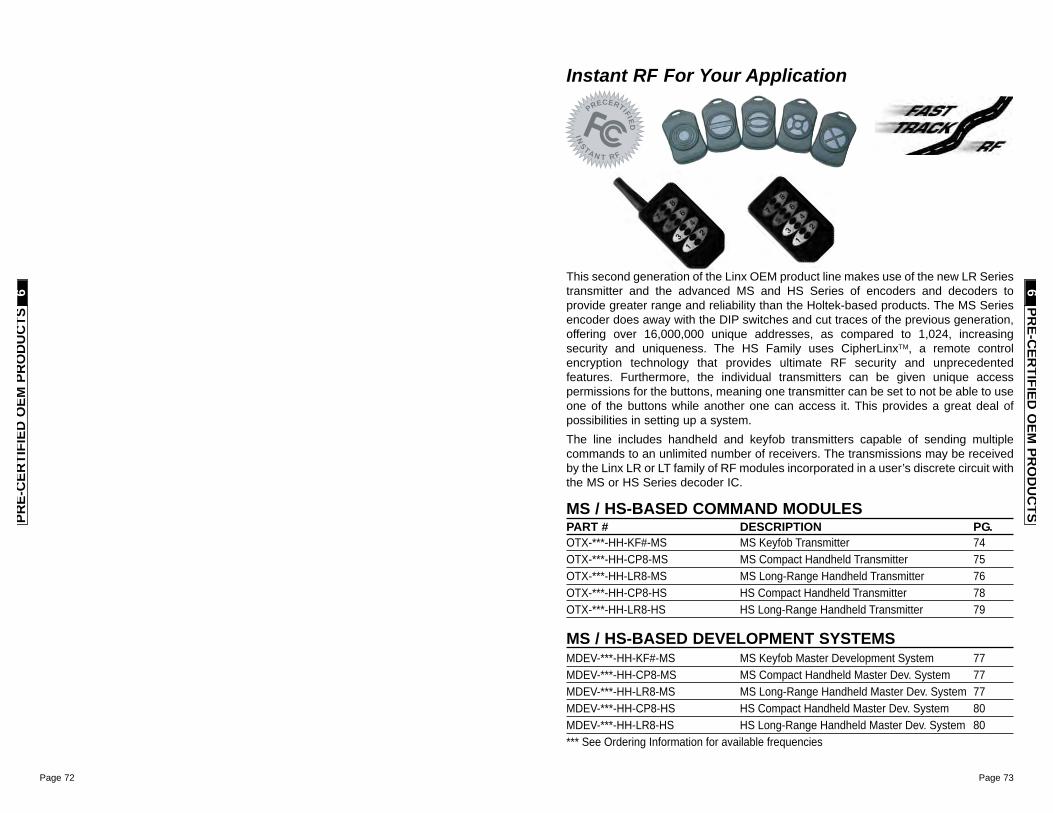
Page 73Page 72
IN
S
TA
NT RF
PRECERT
IFIE
D
Instant RF For Your Application
This second generation of the Linx OEM product line makes use of the new LR Seriestransmitter and the advanced MS and HS Series of encoders and decoders toprovide greater range and reliability than the Holtek-based products. The MS Seriesencoder does away with the DIP switches and cut traces of the previous generation,offering over 16,000,000 unique addresses, as compared to 1,024, increasingsecurity and uniqueness. The HS Family uses CipherLinxTM, a remote controlencryption technology that provides ultimate RF security and unprecedentedfeatures. Furthermore, the individual transmitters can be given unique accesspermissions for the buttons, meaning one transmitter can be set to not be able to useone of the buttons while another one can access it. This provides a great deal ofpossibilities in setting up a system.The line includes handheld and keyfob transmitters capable of sending multiplecommands to an unlimited number of receivers. The transmissions may be receivedby the Linx LR or LT family of RF modules incorporated in a user’s discrete circuit withthe MS or HS Series decoder IC.
MS / HS-BASED COMMAND MODULESPART # DESCRIPTION PG.OTX-***-HH-KF#-MS MS Keyfob Transmitter 74OTX-***-HH-CP8-MS MS Compact Handheld Transmitter 75OTX-***-HH-LR8-MS MS Long-Range Handheld Transmitter 76OTX-***-HH-CP8-HS HS Compact Handheld Transmitter 78OTX-***-HH-LR8-HS HS Long-Range Handheld Transmitter 79
MS / HS-BASED DEVELOPMENT SYSTEMSMDEV-***-HH-KF#-MS MS Keyfob Master Development System 77MDEV-***-HH-CP8-MS MS Compact Handheld Master Dev. System 77MDEV-***-HH-LR8-MS MS Long-Range Handheld Master Dev. System 77MDEV-***-HH-CP8-HS HS Compact Handheld Master Dev. System 80MDEV-***-HH-LR8-HS HS Long-Range Handheld Master Dev. System 80*** See Ordering Information for available frequencies
PRE-C
ERTIFIED
OEM
PRO
DU
CTS
6PR
E-C
ERTI
FIED
OEM
PR
OD
UC
TS6

Page 75
WIRELESS MADE SIMPLE ®
Page 74
WIRELESS MADE SIMPLE ®
DESCRIPTIONThe Linx OTX-***-HH-CP8-MS CompactHandheld Transmitter is ideal for general-purpose remote control and commandapplications. This unit has been pre-certifiedfor FCC Part 15, Industry Canada, andEuropean CE (433MHz only) compliance,reducing costs and time to market. Availablein 315, 418 (standard), or 433.92MHz, thiscompact remote has a transmission range ofup to 750 feet when combined with an LR orLT Series module. The transmitter unit canbe configured with 1 to 8 buttons and thekeypad and labeling can be modified to meetspecific OEM customer requirements. Easeof use and security are dramaticallyenhanced by an on-board MS Seriesencoder, which allows instant creation of upto 16,777,216 (224) unique addresses withoutcumbersome DIP switches or cut traces.When paired with an MS Series decoder,transmitter identity can be determined andbutton permissions established. The unituses a single 3V CR2032 lithium button cell.
FEATURESFCC, Canada, and CE pre-certifiedUtilizes the advanced MS encoder224 unique addresses1 to 8 buttonsSmall packageCustomizable keypad
APPLICATIONS INCLUDEGeneral Remote Control Keyless EntryGarage / Gate OpenersLighting ControlCall SystemsHome / Industrial AutomationWire Elimination
OEM ConfigurationsWith a one-time NRE and minimumorder, Linx can configure the keypadand label areas to meet your specificrequirements. Contact Linx for details.
2.00"
1.35"
R 0.2"
2.81"
1.62" 0.60"0.20"
MS COMPACTHANDHELD TRANSMITTER
PHYSICAL DIMENSIONS
IN
S
TA
NT RF
PRECERT
IFIE
D
PART # DESCRIPTIONOTX-***-HH-CP8-MS-xxx MS Compact Handheld TransmitterMDEV-***-HH-CP8-MS HH-CP8 Master Development System*** = 315, 418 (Standard), 433.92MHzxxx = Color Leave blank for standard Black
ORDERING INFORMATION
PRE-C
ERTIFIED
OEM
PRO
DU
CTS
6
WIRELESS MADE SIMPLE ®
DESCRIPTIONThe Linx MS Series Keyfob transmitter isideal for remote control and command appli-cations. Available in 315, 418 (standard), or433.92MHz versions, it has been pre-certified for FCC Part 15, Industry Canada,and European CE (433MHz) compliance.This dramatically reduces development costand time to market. The high-performancesynthesized design provides superiorfrequency accuracy and minimizes bodyproximity effects. When combined with an LRor LT Series module, the Keyfob can operateat distances of up to 1,000ft. Ease of use andsecurity are dramatically enhanced by theon-board MS Series encoder, which allowsinstant creation of up to 16,777,216 (224)unique addresses without cumbersome DIPswitches or cut traces. When paired with aMS Series decoder, Keyfob identity can bedetermined and button permissionsestablished. The Keyfob is available with 1 to5 buttons and can be custom labeled.
FEATURESFCC, Canada, and CE pre-certifiedUtilizes the advanced MS encoder224 unique addresses1 to 5 buttonsSmall packageCustomizable keypad
APPLICATIONS INCLUDEGeneral Remote Control Keyless EntryGarage / Gate OpenersLighting ControlCall SystemsHome / Industrial AutomationWire Elimination
OEM ConfigurationsWith a one-time NRE and minimumorder, Linx can configure the keypadand label areas to meet your specificrequirements. Contact Linx for details.
2.23"
1.00"
0.45"1.37"
S4
S2
S1 S3S5
PHYSICAL DIMENSIONS
MS KEYFOBTRANSMITTER
IN
S
TA
NT RF
PRECERT
IFIE
D
PART # DESCRIPTIONOTX-***-HH-KF#-MS-xxx MS Keyfob TransmitterMDEV-***-HH-KF#-MS MS Keyfob Master Dev. System# = Number of Buttons: 1 to 5*** = 315, 418 (Standard), 433MHzxxx = Color Leave blank for standard BlackWHT = White CGY= Gray CBL = BlueCRE = Red CPU = Purple
ORDERING INFORMATION
PRE-
CER
TIFI
ED O
EM P
RO
DU
CTS
6
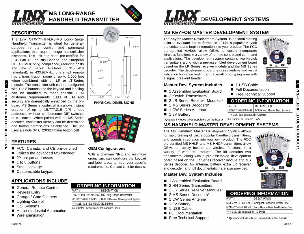
Page 77
WIRELESS MADE SIMPLE ®
Page 76
WIRELESS MADE SIMPLE ®
MS HANDHELD MASTER DEVELOPMENT SYSTEMSThe MS Handheld Master Development System allowsfor rapid testing of Linx’s popular handheld transmitters,and speeds integration into your own product. The FCCpre-certified MS HHLR and MS HHCP transmitters allowOEMs to rapidly incorporate wireless functions in avariety of wireless products. The kit contains twotransmitters, along with a pre-assembled developmentboard based on the LR Series receiver module and MSSeries decoder. An antenna, battery, extra LR receiverand decoder, and full documentation are also provided.
PART # DESCRIPTIONMDEV-***-HH-CP8-MS Compact Handheld Master Dev.MDEV-***-HH-LR8-MS Long-Range Handheld Master Dev.*** = 315, 418 (Standard) , 433MHz
ORDERING INFORMATION
MS KEYFOB MASTER DEVELOPMENT SYSTEMThe Keyfob Master Development System is an ideal startingpoint to evaluate the performance of Linx’s popular Keyfobtransmitters and begin integration into your product. The FCCpre-certified keyfobs allow OEMs to rapidly incorporatewireless functions in a variety of remote control and commandapplications. The development system contains two Keyfobtransmitters along with a pre-assembled development boardbased on the LR Series receiver module and the MS Seriesdecoder. The development board features audible and visualindication for range testing and a small prototyping area witha signal breakout header.
Master Dev. System Includes1 Assembled Evaluation Board2 Keyfob Transmitters2 LR Series Receiver Modules*2 MS Series Decoders*1 CW Series Antenna1 9V Battery
1 USB CableFull DocumentationFree Technical Support
PART # DESCRIPTION MDEV-***-HH-KF#-MS MS Keyfob Master Dev. System*** = 315, 418 (Standard), 433MHz# = Number of Buttons: 1 to 5
ORDERING INFORMATION
Master Dev. System Includes1 Assembled Evaluation Board2 HH Series Transmitters2 LR Series Receiver Modules*2 MS Series Decoders*1 CW Series Antenna1 9V Battery1 USB CableFull DocumentationFree Technical Support
* Quantity includes those populated on the boards
* Quantity includes those populated on the boards
DEVELOPMENT SYSTEMS
PRE-C
ERTIFIED
OEM
PRO
DU
CTS
6
DESCRIPTIONThe Linx OTX-***-HH-LR8-MS Long-RangeHandheld Transmitter is ideal for general-purpose remote control and commandapplications that require longer transmissiondistances. This unit has been pre-certified forFCC Part 15, Industry Canada, and EuropeanCE (433MHz only) compliance, reducing costsand time to market. Available in 315, 418(standard), or 433.92MHz, this small remotehas a transmission range of up to 1,000 feetwhen combined with an LR or LT Seriesmodule. The transmitter unit can be configuredwith 1 to 8 buttons and the keypad and labelingcan be modified to meet specific OEMcustomer requirements. Ease of use andsecurity are dramatically enhanced by the on-board MS Series encoder, which allows instantcreation of up to 16,777,216 (224) uniqueaddresses without cumbersome DIP switchesor cut traces. When paired with an MS Seriesdecoder, transmitter identity can be determinedand button permissions established. The unituses a single 3V CR2032 lithium button cell.
FEATURESFCC, Canada, and CE pre-certifiedUtilizes the advanced MS encoder224 unique addresses 1 to 8 buttonsSmall packageCustomizable keypad
APPLICATIONS INCLUDEGeneral Remote Control Keyless EntryGarage / Gate OpenersLighting ControlCall SystemsHome / Industrial AutomationWire Elimination
OEM ConfigurationsWith a one-time NRE and minimumorder, Linx can configure the keypadand label areas to meet your specificrequirements. Contact Linx for details.
0.60"0.20"
1.375"
2.81"
1.62"
2.00"
1.35"
R 0.2"
MS LONG-RANGEHANDHELD TRANSMITTER
PHYSICAL DIMENSIONS
IN
S
TA
NT RF
PRECERT
IFIE
D
PART # DESCRIPTIONOTX-***-HH-LR8-MS-xxx MS Long-Range TransmitterMDEV-***-HH-LR8-MS HH-LR8 Master Development System*** = 315, 418 (Standard), 433.92MHzxxx = Color Leave blank for standard Black
ORDERING INFORMATION
PRE-
CER
TIFI
ED O
EM P
RO
DU
CTS
6
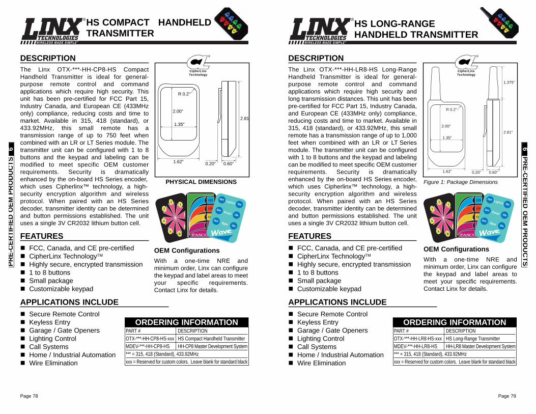
Page 79
WIRELESS MADE SIMPLE ®
Page 78
WIRELESS MADE SIMPLE ®
DESCRIPTIONThe Linx OTX-***-HH-CP8-HS CompactHandheld Transmitter is ideal for general-purpose remote control and commandapplications which require high security. Thisunit has been pre-certified for FCC Part 15,Industry Canada, and European CE (433MHzonly) compliance, reducing costs and time tomarket. Available in 315, 418 (standard), or433.92MHz, this small remote has atransmission range of up to 750 feet whencombined with an LR or LT Series module. Thetransmitter unit can be configured with 1 to 8buttons and the keypad and labeling can bemodified to meet specific OEM customerrequirements. Security is dramaticallyenhanced by the on-board HS Series encoder,which uses Cipherlinx™ technology, a high-security encryption algorithm and wirelessprotocol. When paired with an HS Seriesdecoder, transmitter identity can be determinedand button permissions established. The unituses a single 3V CR2032 lithium button cell.
FEATURESFCC, Canada, and CE pre-certifiedCipherLinx TechnologyTM
Highly secure, encrypted transmission1 to 8 buttonsSmall packageCustomizable keypad
APPLICATIONS INCLUDESecure Remote Control Keyless EntryGarage / Gate OpenersLighting ControlCall SystemsHome / Industrial AutomationWire Elimination
OEM ConfigurationsWith a one-time NRE andminimum order, Linx can configurethe keypad and label areas to meetyour specific requirements.Contact Linx for details.
2.00"
1.35"
R 0.2"
2.81
1.62" 0.60"0.20"
21
3
4
AB
C
D
ON
ON
ON
ON
FASCO
Lights
Spa
ON
ON
ON
OFF
OFF
OFF
Pool
PART # DESCRIPTIONOTX-***-HH-CP8-HS-xxx HS Compact Handheld TransmitterMDEV-***-HH-CP8-HS HH-CP8 Master Development System*** = 315, 418 (Standard), 433.92MHzxxx = Reserved for custom colors. Leave blank for standard black
ORDERING INFORMATION
CipherLinx
Technology
®
HS COMPACT HANDHELDTRANSMITTER
PHYSICAL DIMENSIONS
DESCRIPTIONThe Linx OTX-***-HH-LR8-HS Long-RangeHandheld Transmitter is ideal for general-purpose remote control and commandapplications which require high security andlong transmission distances. This unit has beenpre-certified for FCC Part 15, Industry Canada,and European CE (433MHz only) compliance,reducing costs and time to market. Available in315, 418 (standard), or 433.92MHz, this smallremote has a transmission range of up to 1,000feet when combined with an LR or LT Seriesmodule. The transmitter unit can be configuredwith 1 to 8 buttons and the keypad and labelingcan be modified to meet specific OEM customerrequirements. Security is dramaticallyenhanced by the on-board HS Series encoder,which uses Cipherlinx™ technology, a high-security encryption algorithm and wirelessprotocol. When paired with an HS Seriesdecoder, transmitter identity can be determinedand button permissions established. The unituses a single 3V CR2032 lithium button cell.
FEATURESFCC, Canada, and CE pre-certifiedCipherLinx TechnologyTM
Highly secure, encrypted transmission1 to 8 buttonsSmall packageCustomizable keypad
APPLICATIONS INCLUDESecure Remote Control Keyless EntryGarage / Gate OpenersLighting ControlCall SystemsHome / Industrial AutomationWire Elimination
OEM ConfigurationsWith a one-time NRE andminimum order, Linx can configurethe keypad and label areas tomeet your specific requirements.Contact Linx for details.
0.60"0.20"
1.375"
2.81"
1.62"
2.00"
1.35"
R 0.2"
Figure 1: Package Dimensions
21
3
4
AB
C
D
ON
ON
ON
ON
FASCO
Lights
Spa
ON
ON
ON
OFF
OFF
OFF
Pool
PART # DESCRIPTIONOTX-***-HH-LR8-HS-xxx HS Long-Range TransmitterMDEV-***-HH-LR8-HS HH-LR8 Master Development System*** = 315, 418 (Standard), 433.92MHzxxx = Reserved for custom colors. Leave blank for standard black
ORDERING INFORMATION
CipherLinx
Technology
®
HS LONG-RANGEHANDHELD TRANSMITTER
PRE-
CER
TIFI
ED O
EM P
RO
DU
CTS
6PR
E-CER
TIFIED O
EM PR
OD
UC
TS6
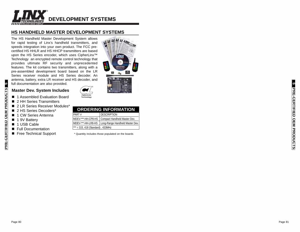
Page 80
WIRELESS MADE SIMPLE ®
Page 81
HS HANDHELD MASTER DEVELOPMENT SYSTEMSThe HS Handheld Master Development System allowsfor rapid testing of Linx’s handheld transmitters, andspeeds integration into your own product. The FCC pre-certified HS HHLR and HS HHCP transmitters are basedupon the HS Series encoder, which uses CipherLinx™Technology an encrypted remote control technology thatprovides ultimate RF security and unprecedentedfeatures. The kit contains two transmitters, along with apre-assembled development board based on the LRSeries receiver module and HS Series decoder. Anantenna, battery, extra LR receiver and HS decoder, andfull documentation are also provided.
PART # DESCRIPTIONMDEV-***-HH-CP8-HS Compact Handheld Master Dev.MDEV-***-HH-LR8-HS Long-Range Handheld Master Dev.*** = 315, 418 (Standard) , 433MHz
ORDERING INFORMATION
Master Dev. System Includes1 Assembled Evaluation Board2 HH Series Transmitters2 LR Series Receiver Modules*2 HS Series Decoders*1 CW Series Antenna1 9V Battery1 USB CableFull DocumentationFree Technical Support * Quantity includes those populated on the boards
PRE-C
ERTIFIED
OEM
PRO
DU
CTS
6
DEVELOPMENT SYSTEMS
PRE-
CER
TIFI
ED O
EM P
RO
DU
CTS
6
CipherLinx
Technology
®
Page 83
Welcome to the Products & Services of
Phone: (541) 956-0931Fax: (541) [email protected]
About Antenna FactorAntenna Factor focuses on cost-effective standard and customantennas designed for a wide range of consumer and industrialwireless products. With one of the broadest and mostcomprehensive antenna lines in the industry, we have helpedcompanies of all sizes meet the mechanical, electrical, andaesthetic requirements of their wireless products. From tinyembeddable chip antennas to GPS and high-gain Yagi antennas,you can find them here.
Our specialty is compact antennas intended for use oncompromised ground planes, such as those commonly found inhandheld and portable products. We recognize that ourcomponents are a critical factor in determining the range andreliability of a wireless product. Making the correct design choicesis often a balance of complex issues ranging from cosmeticattractiveness to legal considerations. We work with each customerto ensure optimum performance and satisfaction with our products.
Antenna Factor not only offers a broad range of standard productsbut can also deliver anything from a slight modification to a groundup antenna design. From color-to-shape, frequency-to-wavelengthAntenna Factor stands ready to assist with your custom antennarequirements.
By combining responsive customer service, individualized technicalsupport, world class quality, outstanding value and custom designcapabilities, Antenna Factor hopes to be your antenna supplier ofchoice.
Page 82
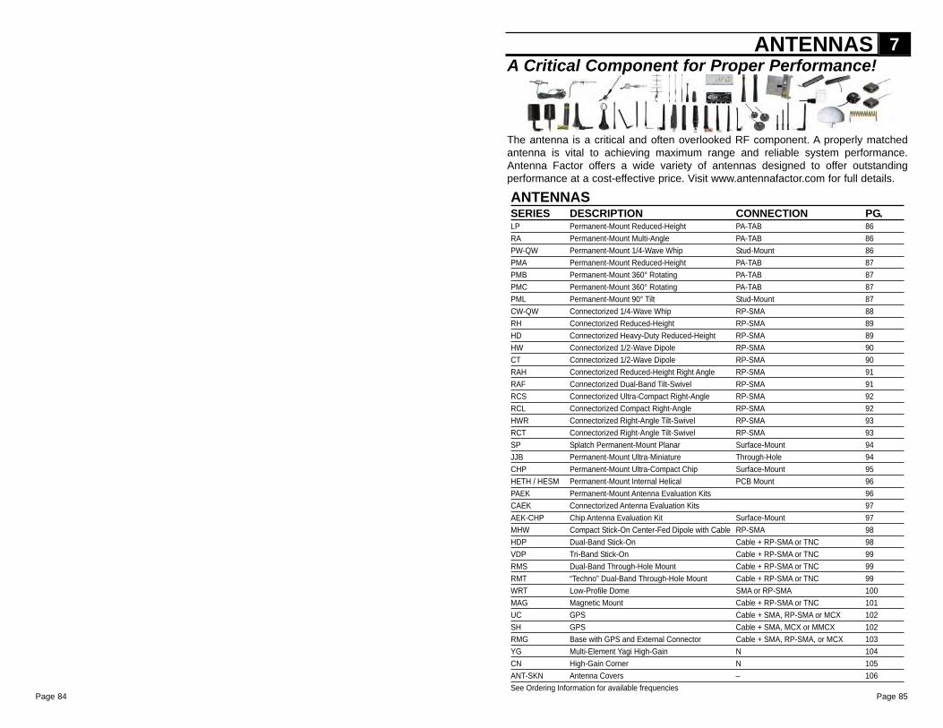
Page 85
The antenna is a critical and often overlooked RF component. A properly matchedantenna is vital to achieving maximum range and reliable system performance.Antenna Factor offers a wide variety of antennas designed to offer outstandingperformance at a cost-effective price. Visit www.antennafactor.com for full details.
ANTENNASSERIES DESCRIPTION CONNECTION PG.LP Permanent-Mount Reduced-Height PA-TAB 86RA Permanent-Mount Multi-Angle PA-TAB 86PW-QW Permanent-Mount 1/4-Wave Whip Stud-Mount 86PMA Permanent-Mount Reduced-Height PA-TAB 87PMB Permanent-Mount 360° Rotating PA-TAB 87PMC Permanent-Mount 360° Rotating PA-TAB 87PML Permanent-Mount 90° Tilt Stud-Mount 87CW-QW Connectorized 1/4-Wave Whip RP-SMA 88RH Connectorized Reduced-Height RP-SMA 89HD Connectorized Heavy-Duty Reduced-Height RP-SMA 89HW Connectorized 1/2-Wave Dipole RP-SMA 90CT Connectorized 1/2-Wave Dipole RP-SMA 90RAH Connectorized Reduced-Height Right Angle RP-SMA 91RAF Connectorized Dual-Band Tilt-Swivel RP-SMA 91RCS Connectorized Ultra-Compact Right-Angle RP-SMA 92RCL Connectorized Compact Right-Angle RP-SMA 92HWR Connectorized Right-Angle Tilt-Swivel RP-SMA 93RCT Connectorized Right-Angle Tilt-Swivel RP-SMA 93SP Splatch Permanent-Mount Planar Surface-Mount 94JJB Permanent-Mount Ultra-Miniature Through-Hole 94CHP Permanent-Mount Ultra-Compact Chip Surface-Mount 95HETH / HESM Permanent-Mount Internal Helical PCB Mount 96PAEK Permanent-Mount Antenna Evaluation Kits 96CAEK Connectorized Antenna Evaluation Kits 97AEK-CHP Chip Antenna Evaluation Kit Surface-Mount 97MHW Compact Stick-On Center-Fed Dipole with Cable RP-SMA 98HDP Dual-Band Stick-On Cable + RP-SMA or TNC 98VDP Tri-Band Stick-On Cable + RP-SMA or TNC 99RMS Dual-Band Through-Hole Mount Cable + RP-SMA or TNC 99RMT “Techno” Dual-Band Through-Hole Mount Cable + RP-SMA or TNC 99WRT Low-Profile Dome SMA or RP-SMA 100MAG Magnetic Mount Cable + RP-SMA or TNC 101UC GPS Cable + SMA, RP-SMA or MCX 102SH GPS Cable + SMA, MCX or MMCX 102RMG Base with GPS and External Connector Cable + SMA, RP-SMA, or MCX 103YG Multi-Element Yagi High-Gain N 104CN High-Gain Corner N 105ANT-SKN Antenna Covers – 106See Ordering Information for available frequencies
ANTENNAS 7A Critical Component for Proper Performance!
Page 84
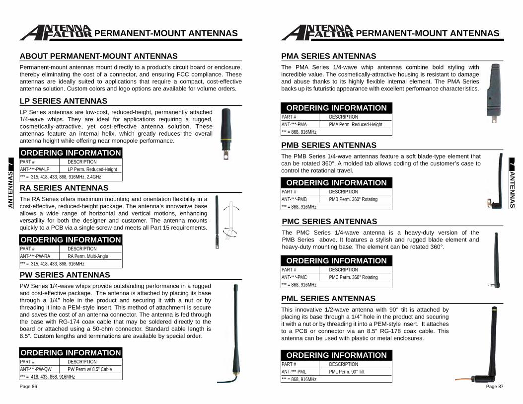
Page 87Page 86
PMB SERIES ANTENNASThe PMB Series 1/4-wave antennas feature a soft blade-type element thatcan be rotated 360°. A molded tab allows coding of the customer’s case tocontrol the rotational travel.
PMA SERIES ANTENNASThe PMA Series 1/4-wave whip antennas combine bold styling withincredible value. The cosmetically-attractive housing is resistant to damageand abuse thanks to its highly flexible internal element. The PMA Seriesbacks up its futuristic appearance with excellent performance characteristics.
PML SERIES ANTENNASThis innovative 1/2-wave antenna with 90° tilt is attached byplacing its base through a 1/4” hole in the product and securingit with a nut or by threading it into a PEM-style insert. It attachesto a PCB or connector via an 8.5” RG-178 coax cable. Thisantenna can be used with plastic or metal enclosures.
PMC SERIES ANTENNASThe PMC Series 1/4-wave antenna is a heavy-duty version of thePMB Series above. It features a stylish and rugged blade element andheavy-duty mounting base. The element can be rotated 360°.
AN
TENN
AS
7
PERMANENT-MOUNT ANTENNAS
PART # DESCRIPTIONANT-***-PMA PMA Perm. Reduced-Height*** = 868, 916MHz
ORDERING INFORMATION
PART # DESCRIPTIONANT-***-PMB PMB Perm. 360° Rotating*** = 868, 916MHz
ORDERING INFORMATION
PART # DESCRIPTIONANT-***-PMC PMC Perm. 360° Rotating*** = 868, 916MHz
ORDERING INFORMATION
PART # DESCRIPTIONANT-***-PML PML Perm. 90° Tilt*** = 868, 916MHz
ORDERING INFORMATION
ABOUT PERMANENT-MOUNT ANTENNASPermanent-mount antennas mount directly to a product’s circuit board or enclosure,thereby eliminating the cost of a connector, and ensuring FCC compliance. Theseantennas are ideally suited to applications that require a compact, cost-effectiveantenna solution. Custom colors and logo options are available for volume orders.
LP SERIES ANTENNASLP Series antennas are low-cost, reduced-height, permanently attached1/4-wave whips. They are ideal for applications requiring a rugged,cosmetically-attractive, yet cost-effective antenna solution. Theseantennas feature an internal helix, which greatly reduces the overallantenna height while offering near monopole performance.
RA SERIES ANTENNASThe RA Series offers maximum mounting and orientation flexibility in acost-effective, reduced-height package. The antenna’s innovative baseallows a wide range of horizontal and vertical motions, enhancingversatility for both the designer and customer. The antenna mountsquickly to a PCB via a single screw and meets all Part 15 requirements.
PART # DESCRIPTIONANT-***-PW-QW PW Perm w/ 8.5” Cable*** = 418, 433, 868, 916MHz
ORDERING INFORMATION
PW SERIES ANTENNASPW Series 1/4-wave whips provide outstanding performance in a ruggedand cost-effective package. The antenna is attached by placing its basethrough a 1/4” hole in the product and securing it with a nut or bythreading it into a PEM-style insert. This method of attachment is secureand saves the cost of an antenna connector. The antenna is fed throughthe base with RG-174 coax cable that may be soldered directly to theboard or attached using a 50-ohm connector. Standard cable length is8.5”. Custom lengths and terminations are available by special order.
PERMANENT-MOUNT ANTENNAS
AN
TEN
NA
S7 PART # DESCRIPTION
ANT-***-PW-LP LP Perm. Reduced-Height*** = 315, 418, 433, 868, 916MHz, 2.4GHz
ORDERING INFORMATION
PART # DESCRIPTIONANT-***-PW-RA RA Perm. Multi-Angle*** = 315, 418, 433, 868, 916MHz
ORDERING INFORMATION
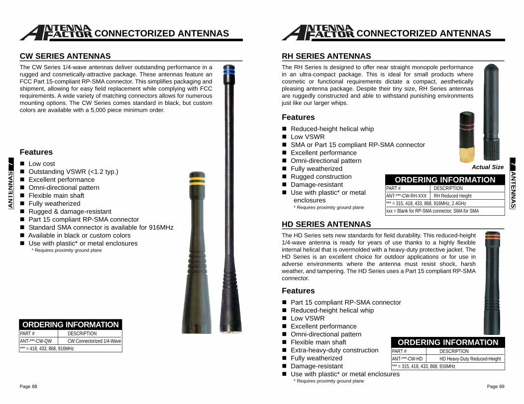
Page 89Page 88
FeaturesPart 15 compliant RP-SMA connectorReduced-height helical whipLow VSWRExcellent performanceOmni-directional patternFlexible main shaftExtra-heavy-duty constructionFully weatherizedDamage-resistantUse with plastic* or metal enclosures
* Requires proximity ground plane
HD SERIES ANTENNASThe HD Series sets new standards for field durability. This reduced-height1/4-wave antenna is ready for years of use thanks to a highly flexibleinternal helical that is overmolded with a heavy-duty protective jacket. TheHD Series is an excellent choice for outdoor applications or for use inadverse environments where the antenna must resist shock, harshweather, and tampering. The HD Series uses a Part 15 compliant RP-SMAconnector.
RH SERIES ANTENNASThe RH Series is designed to offer near straight monopole performancein an ultra-compact package. This is ideal for small products wherecosmetic or functional requirements dictate a compact, aestheticallypleasing antenna package. Despite their tiny size, RH Series antennasare ruggedly constructed and able to withstand punishing environmentsjust like our larger whips.
FeaturesReduced-height helical whipLow VSWRSMA or Part 15 compliant RP-SMA connectorExcellent performanceOmni-directional patternFully weatherizedRugged constructionDamage-resistantUse with plastic* or metal enclosures* Requires proximity ground plane
PART # DESCRIPTIONANT-***-CW-HD HD Heavy-Duty Reduced-Height*** = 315, 418, 433, 868, 916MHz
ORDERING INFORMATION
PART # DESCRIPTIONANT-***-CW-RH-XXX RH Reduced Height*** = 315, 418, 433, 868, 916MHz, 2.4GHzxxx = Blank for RP-SMA connector, SMA for SMA
ORDERING INFORMATIONActual Size
CONNECTORIZED ANTENNAS
AN
TENN
AS
7
FeaturesLow costOutstanding VSWR (<1.2 typ.)Excellent performanceOmni-directional patternFlexible main shaftFully weatherizedRugged & damage-resistantPart 15 compliant RP-SMA connectorStandard SMA connector is available for 916MHzAvailable in black or custom colorsUse with plastic* or metal enclosures
* Requires proximity ground plane
PART # DESCRIPTIONANT-***-CW-QW CW Connectorized 1/4-Wave*** = 418, 433, 868, 916MHz
ORDERING INFORMATION
CW SERIES ANTENNASThe CW Series 1/4-wave antennas deliver outstanding performance in arugged and cosmetically-attractive package. These antennas feature anFCC Part 15-compliant RP-SMA connector. This simplifies packaging andshipment, allowing for easy field replacement while complying with FCCrequirements. A wide variety of matching connectors allows for numerousmounting options. The CW Series comes standard in black, but customcolors are available with a 5,000 piece minimum order.
CONNECTORIZED ANTENNAS
AN
TEN
NA
S7
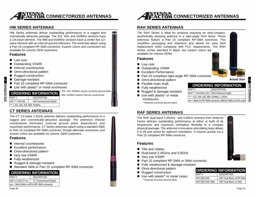
Page 91Page 90
CONNECTORIZED ANTENNAS
RAH SERIES ANTENNASThe RAH Series is ideal for products requiring an ultra-compact,aesthetically pleasing antenna in a right-angle form factor. Theseantennas feature a Part 15 compliant RP-SMA connector. Thissimplifies packaging and shipment and allows for easy fieldreplacement while complying with FCC requirements. The RAHSeries comes standard in black, but custom colors areavailable for volume OEMs.
FeaturesLow cost Outstanding VSWRExcellent PerformancePart 15 compliant right-angle RP-SMA connector Omni-directional pattern Flexible main shaftFully weatherizedRugged & damage-resistantUse with plastic* or metal enclosures* Requires proximity ground plane
PART # DESCRIPTIONANT-***-CW-RAH-XXX RAH Reduced Height*** = 315, 418, 433, 868, 916MHz, 2.4GHzxxx = Blank for RP-SMA connector, SMA for SMA (2.4GHz only)
ORDERING INFORMATIONActual Size
RAF SERIES ANTENNASThe RAF dual-band 2.45GHz and 5.8GHz antenna from AntennaFactor delivers outstanding performance at either or both of itsfrequencies and maximum orientation flexibility in a compactphysical package. The antenna’s innovative articulating base allowsit to tilt and swivel for optimum orientation. It mounts quickly via aPart 15 compliant RP-SMA connector.
FeaturesTilts and rotatesDual-band 2.45GHz and 5.8GHzVery low VSWRPart 15 compliant RP-SMA or SMA connectorFully weatherized & damage-resistant Omni-directional patternRugged constructionUse with plastic* or metal cases
* Requires proximity ground plane
PART # DESCRIPTIONANT-DB1-RAF RAF Dual Band, w/ RP-SMAANT-DB1-RAF-SMA RAF Dual Band, w/ SMA
ORDERING INFORMATION
AN
TENN
AS
7
CONNECTORIZED ANTENNAS
HW SERIES ANTENNASHW Series antennas deliver outstanding performance in a rugged andcosmetically attractive package. The 315, 418, and 433MHz versions havea 1/4-wave element. The 868 and 916MHz versions have a center-fed 1/2-wave element with an internal ground reference. The antennas attach usinga Part 15 compliant RP-SMA connector. Custom colors and connectors areavailable for volume OEM customers.Features
Low cost Outstanding VSWR Internal counterpoise Omni-directional pattern Rugged construction Damage-resistant Part 15 compliant RP-SMA connector Use with plastic* or metal enclosures
PART # DESCRIPTIONANT-***-CW-HW HW Connectorized Dipole*** = 315, 418, 433, 868, 916MHz
ORDERING INFORMATION
AN
TEN
NA
S7
CT SERIES ANTENNASThe CT 1/2-wave 2.4GHz antenna delivers outstanding performance in arugged and cosmetically-attractive package. The antenna’s internalcounterpoise eliminates external ground plane dependence andmaximizes performance. CT Series antennas attach using a standard SMAor Part 15 compliant RP-SMA connector, though alternate connectors andcustom colors are available for volume OEM customers.Features
Internal counterpoiseExcellent performanceOmni-directional patternVery low VSWRFully weatherizedRugged & damage-resistantStandard SMA or Part 15 compliant RP-SMA connector
PART # DESCRIPTIONANT-2.4-CW-CT-xxx CT Connectorized Dipolexxx = SMA (SMA) or RPS (RP-SMA) connector
ORDERING INFORMATION
* 315, 418, 433MHz require proximity ground plane
* 868, 916MHz feature internal counterpoise
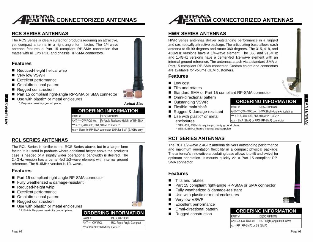
Page 93Page 92
HWR SERIES ANTENNASHWR Series antennas deliver outstanding performance in a ruggedand cosmetically attractive package. The articulating base allows eachantenna to tilt 90 degrees and rotate 360 degrees. The 315, 418, and433MHz versions have a 1/4-wave element. The 868 and 916MHzand 1.4GHz versions have a center-fed 1/2-wave element with aninternal ground reference. The antennas attach via a standard SMA orPart 15 compliant RP-SMA connector. Custom colors and connectorsare available for volume OEM customers.
RCT SERIES ANTENNASThe RCT 1/2-wave 2.4GHz antenna delivers outstanding performanceand maximum orientation flexibility in a compact physical package.The antenna’s innovative articulating base allows it to tilt and swivel foroptimum orientation. It mounts quickly via a Part 15 compliant RP-SMA connector.
PART # DESCRIPTIONANT-***-CW-HWR-xxx HWR Right-Angle Articulating*** = 315, 418, 433, 868, 916MHz, 1.4GHzxxx = SMA (SMA) or RPS (RP-SMA) connector
ORDERING INFORMATION
PART # DESCRIPTIONANT-2.4-CW-RCT-xx RCT Right-Angle Half-Wavexx = RP (RP-SMA) or SS (SMA)
ORDERING INFORMATION
FeaturesLow costTilts and rotatesStandard SMA or Part 15 compliant RP-SMA connectorOmni-directional patternOutstanding VSWRFlexible main shaftRugged & damage-resistantUse with plastic* or metalenclosures * 315, 418, 433MHz require proximity ground plane,* 868, 916MHz feature internal counterpoise
FeaturesTilts and rotatesPart 15 compliant right-angle RP-SMA or SMA connectorFully weatherized & damage-resistantUse with plastic or metal enclosuresVery low VSWRExcellent performanceOmni-directional patternRugged construction
CONNECTORIZED ANTENNAS
AN
TENN
AS
7
RCL SERIES ANTENNASThe RCL Series is similar to the RCS Series above, but in a larger formfactor. It is useful in products where additional height above the product’scase is needed or a slightly wider operational bandwidth is desired. The2.4GHz version has a center-fed 1/2-wave element with internal groundreference. The 916MHz version is 1/4-wave.
PART # DESCRIPTIONANT-***-CW-RCL RCL Right-Angle Compact *** = 916 (902-928MHz), 2.4GHz
ORDERING INFORMATION
FeaturesReduced-height helical whipVery low VSWRExcellent performanceOmni-directional patternRugged constructionPart 15 compliant right-angle RP-SMA or SMA connectorUse with plastic* or metal enclosures
* Requires proximity ground plane
FeaturesPart 15 compliant right-angle RP-SMA connectorFully weatherized & damage-resistantReduced-height whipExcellent performanceOmni-directional patternRugged constructionUse with plastic* or metal enclosures
* 916MHz Requires proximity ground plane
RCS SERIES ANTENNASThe RCS Series is ideally suited for products requiring an attractive,yet compact antenna in a right-angle form factor. The 1/4-waveantenna features a Part 15 compliant RP-SMA connection thatmates with all Linx PCB and chassis RP-SMA connectors.
Actual Size
PART # DESCRIPTIONANT-***-CW-RCS-xxx Rt-Angle Reduced-Height w/ RP-SMA*** = 315, 418, 433, 868, 916MHz, 2.4GHzxxx = Blank for RP-SMA connector, SMA for SMA (2.4GHz only)
ORDERING INFORMATION
CONNECTORIZED ANTENNAS
AN
TEN
NA
S7
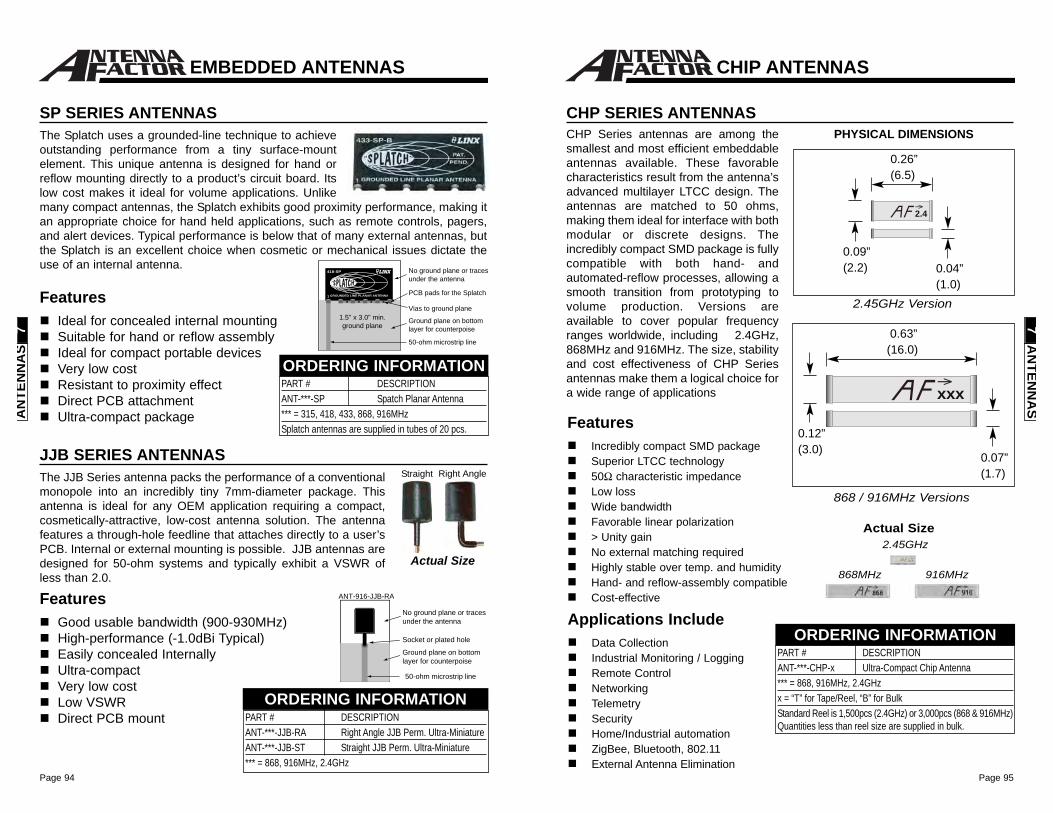
Page 95Page 94
FeaturesIncredibly compact SMD packageSuperior LTCC technology50Ω characteristic impedanceLow lossWide bandwidthFavorable linear polarization> Unity gainNo external matching requiredHighly stable over temp. and humidityHand- and reflow-assembly compatibleCost-effective
CHIP ANTENNAS
CHP SERIES ANTENNAS
Applications IncludeData CollectionIndustrial Monitoring / LoggingRemote ControlNetworkingTelemetrySecurityHome/Industrial automationZigBee, Bluetooth, 802.11External Antenna Elimination
PHYSICAL DIMENSIONS
2.4
xxx
0.63”(16.0)
0.12”(3.0)
CHP Series antennas are among thesmallest and most efficient embeddableantennas available. These favorablecharacteristics result from the antenna’sadvanced multilayer LTCC design. Theantennas are matched to 50 ohms,making them ideal for interface with bothmodular or discrete designs. Theincredibly compact SMD package is fullycompatible with both hand- andautomated-reflow processes, allowing asmooth transition from prototyping tovolume production. Versions areavailable to cover popular frequencyranges worldwide, including 2.4GHz,868MHz and 916MHz. The size, stabilityand cost effectiveness of CHP Seriesantennas make them a logical choice fora wide range of applications
0.07”(1.7)
0.09”(2.2) 0.04”
(1.0)
0.26”(6.5)
2.45GHz Version
868 / 916MHz Versions
PART # DESCRIPTIONANT-***-CHP-x Ultra-Compact Chip Antenna*** = 868, 916MHz, 2.4GHzx = “T” for Tape/Reel, “B” for BulkStandard Reel is 1,500pcs (2.4GHz) or 3,000pcs (868 & 916MHz)Quantities less than reel size are supplied in bulk.
ORDERING INFORMATION
Actual Size2.45GHz
868MHz 916MHz
AN
TENN
AS
7
EMBEDDED ANTENNAS
SP SERIES ANTENNASThe Splatch uses a grounded-line technique to achieveoutstanding performance from a tiny surface-mountelement. This unique antenna is designed for hand orreflow mounting directly to a product’s circuit board. Itslow cost makes it ideal for volume applications. Unlikemany compact antennas, the Splatch exhibits good proximity performance, making itan appropriate choice for hand held applications, such as remote controls, pagers,and alert devices. Typical performance is below that of many external antennas, butthe Splatch is an excellent choice when cosmetic or mechanical issues dictate theuse of an internal antenna.
FeaturesIdeal for concealed internal mountingSuitable for hand or reflow assemblyIdeal for compact portable devicesVery low costResistant to proximity effectDirect PCB attachmentUltra-compact package
PART # DESCRIPTIONANT-***-SP Spatch Planar Antenna*** = 315, 418, 433, 868, 916MHzSplatch antennas are supplied in tubes of 20 pcs.
ORDERING INFORMATION
JJB SERIES ANTENNASThe JJB Series antenna packs the performance of a conventionalmonopole into an incredibly tiny 7mm-diameter package. Thisantenna is ideal for any OEM application requiring a compact,cosmetically-attractive, low-cost antenna solution. The antennafeatures a through-hole feedline that attaches directly to a user’sPCB. Internal or external mounting is possible. JJB antennas aredesigned for 50-ohm systems and typically exhibit a VSWR ofless than 2.0.
PART # DESCRIPTIONANT-***-JJB-RA Right Angle JJB Perm. Ultra-Miniature ANT-***-JJB-ST Straight JJB Perm. Ultra-Miniature*** = 868, 916MHz, 2.4GHz
ORDERING INFORMATION
Actual Size
FeaturesGood usable bandwidth (900-930MHz)High-performance (-1.0dBi Typical)Easily concealed InternallyUltra-compactVery low costLow VSWRDirect PCB mount
Straight Right Angle
No ground plane or tracesunder the antenna
Ground plane on bottomlayer for counterpoise
50-ohm microstrip line
Socket or plated hole
ANT-916-JJB-RA
No ground plane or tracesunder the antenna
Ground plane on bottomlayer for counterpoise
50-ohm microstrip line
Vias to ground plane
11 GROUNDED LINE PLANAR ANTENNA
418-SP
PCB pads for the Splatch
1.5" x 3.0" min.ground plane
AN
TEN
NA
S7
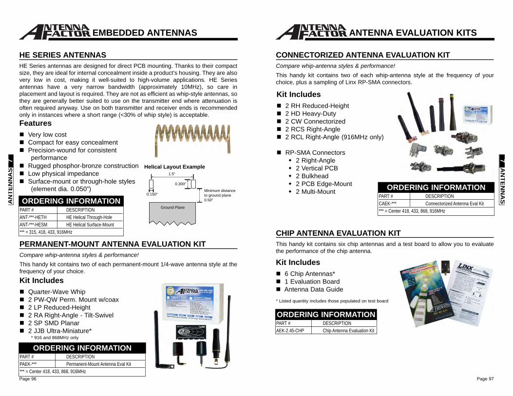
Page 97Page 96
ANTENNA EVALUATION KITS
CHIP ANTENNA EVALUATION KITThis handy kit contains six chip antennas and a test board to allow you to evaluatethe performance of the chip antenna.
Kit Includes6 Chip Antennas*1 Evaluation BoardAntenna Data Guide
PART # DESCRIPTIONAEK-2.45-CHP Chip Antenna Evaluation Kit
ORDERING INFORMATION
* Listed quantity includes those populated on test board
CONNECTORIZED ANTENNA EVALUATION KITCompare whip-antenna styles & performance!This handy kit contains two of each whip-antenna style at the frequency of yourchoice, plus a sampling of Linx RP-SMA connectors.
Kit Includes2 RH Reduced-Height 2 HD Heavy-Duty 2 CW Connectorized2 RCS Right-Angle2 RCL Right-Angle (916MHz only)
RP-SMA Connectors2 Right-Angle2 Vertical PCB2 Bulkhead2 PCB Edge-Mount2 Multi-Mount
PART # DESCRIPTIONCAEK-*** Connectorized Antenna Eval Kit*** = Center 418, 433, 868, 916MHz
ORDERING INFORMATION
AN
TENN
AS
7
EMBEDDED ANTENNAS
HE SERIES ANTENNASHE Series antennas are designed for direct PCB mounting. Thanks to their compactsize, they are ideal for internal concealment inside a product’s housing. They are alsovery low in cost, making it well-suited to high-volume applications. HE Seriesantennas have a very narrow bandwidth (approximately 10MHz), so care inplacement and layout is required. They are not as efficient as whip-style antennas, sothey are generally better suited to use on the transmitter end where attenuation isoften required anyway. Use on both transmitter and receiver ends is recommendedonly in instances where a short range (<30% of whip style) is acceptable.Features
Very low costCompact for easy concealmentPrecision-wound for consistentperformance
Rugged phosphor-bronze constructionLow physical impedanceSurface-mount or through-hole styles(element dia. 0.050”)
1.5"
0.150"
0.300"
Ground Plane
Minimum distance to ground plane0.50"
Helical Layout Example
PART # DESCRIPTIONANT-***-HETH HE Helical Through-HoleANT-***-HESM HE Helical Surface-Mount*** = 315, 418, 433, 916MHz
ORDERING INFORMATION
PERMANENT-MOUNT ANTENNA EVALUATION KITCompare whip-antenna styles & performance!This handy kit contains two of each permanent-mount 1/4-wave antenna style at thefrequency of your choice.
Kit IncludesQuarter-Wave Whip2 PW-QW Perm. Mount w/coax2 LP Reduced-Height 2 RA Right-Angle - Tilt-Swivel 2 SP SMD Planar 2 JJB Ultra-Miniature*
* 916 and 868MHz only
PART # DESCRIPTIONPAEK-*** Permanent-Mount Antenna Eval Kit*** = Center 418, 433, 868, 916MHz
ORDERING INFORMATION
AN
TEN
NA
S7
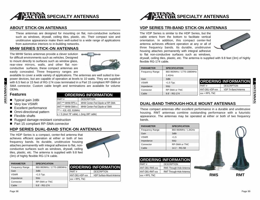
Page 99Page 98
VDP SERIES TRI-BAND STICK-ON ANTENNASThe VDP Series is similar to the HDP Series, but thecable enters from the bottom to facilitate verticalorientation. In addition, this compact center-fedantenna achieves efficient operation at any or all ofthree frequency bands. Its durable, unobtrusivehousing attaches permanently with integral adhesiveto flat non-conductive surfaces such as windows,drywall, ceiling tiles, plastic, etc. The antenna is supplied with 9.8 feet (3m) of highlyflexible RG-174 cable.
PART # DESCRIPTIONANT-DB1-VDP-xxx VDP Tri-Band Antennaxxx = RPS, TNC
ORDERING INFORMATION
PARAMETER SPECIFICATIONFrequency Range 860-960MHz / 1770-1880MHz
2.4GHzGain 3dBiVSWR <1.5 Typ.Impedance 50ΩConnector RP-SMA or TNCCable 9.8’ - RG-174
SPECIALTY ANTENNAS
DUAL-BAND THROUGH-HOLE MOUNT ANTENNASThese compact antennas offer excellent performance in a durable and unobtrusivehousing. RMT antennas combine outstanding performance with a futuristicappearance. The antennas may be operated at either or both of two frequencybands.
PART # DESCRIPTIONANT-DB1-RMS-xxx RMS Through-Hole AntennaANT-DB1-RMT-xxx RMT Through-Hole Antennaxxx = RPS, TNC
ORDERING INFORMATION
RMS RMT
PARAMETER SPECIFICATIONFrequency Range 860-960MHz / 1.8GHzGain 3dBiVSWR <1.5Impedance 50ΩConnector RP-SMA or TNCCable 14.1’ - RG-58
AN
TENN
AS
7
ABOUT STICK-ON ANTENNASThese antennas are designed for mounting on flat, non-conductive surfacessuch as windows, drywall, ceiling tiles, plastic, etc. Their compact size andunobtrusive appearance make them well-suited to a wide range of applicationsfrom automotive interiors to in-building networks.
FeaturesTypical gain 2dBiVery low VSWRExcellent performanceOmni-directional patternFlexible shaftsRugged damage-resistant constructionPart 15 compliant RP-SMA connector
PART # DESCRIPTIONANT-***-MHW-RPS-x MHW Center-Fed Dipole w/ RP-SMAANT-***-MHW-SMA-x MHW Center-Fed Dipole w/ SMA*** = 418, 433, 916MHzx = S (short 78” cable), L (long 180” cable)
ORDERING INFORMATION
MHW SERIES STICK-ON ANTENNASThe MHW Series antennas provide a clever solutionfor difficult environments such as vehicles. Designedto mount directly to surfaces such as window glass,rear-view mirrors, walls, and other flat non-conductive surfaces, these compact antennas areeasily concealed. Three frequency ranges areavailable to cover a wide variety of applications. The antennas are well suited to low-power devices, but are capable of operation at levels to 10 watts. They are suppliedwith 6.5 feet or 15 feet of RG-174 coax terminated in a Part 15 compliant RP-SMA orSMA connector. Custom cable length and terminations are available for volumeOEMs.
HDP SERIES DUAL-BAND STICK-ON ANTENNASThe HDP Series is a compact, center-fed antenna thatachieves efficient operation at either or both of twofrequency bands. Its durable, unobtrusive housingattaches permanently with integral adhesive to flat, non-conductive surfaces such as windows, drywall, ceilingtiles, plastic, etc. The antenna is supplied with 9.8 feet(3m) of highly flexible RG-174 cable.
PART # DESCRIPTIONANT-DB1-HDP-xxx HDP Surface-Mount Antennaxxx = RPS, TNC
ORDERING INFORMATIONPARAMETER SPECIFICATIONFrequency Range 860-960MHz / 1770-1880MHzGain 3dBiVSWR <1.5 Typ.Impedance 50ΩConnector RP-SMA or TNCCable 9.8’ - RG-174
SPECIALTY ANTENNAS
AN
TEN
NA
S7
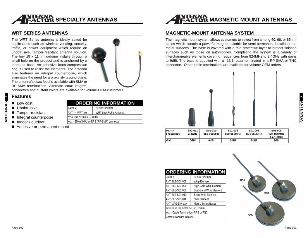
Page 101Page 100
ORDERING INFORMATION
MAGNETIC-MOUNT ANTENNA SYSTEMThe magnetic mount system allows customers to select from among 40, 66, or 85mmbases which contain a powerful magnet suitable for semi-permanent installation onmetal surfaces. The base is covered with a thin protective layer to protect finishedsurfaces such as those on automobiles. Completing the system is a variety ofinterchangeable elements covering frequencies from 824MHz to 2.4GHz with gainsto 9dBi. The base is supplied with a 13.1’ coax terminated in a RP-SMA or TNCconnector. Other cable terminations are available for volume OEM orders.
B50
B66
B85
PART # DESCRIPTIONANT-ELE-S01-005 Whip ElementANT-ELE-S01-006 High-Gain Whip ElementANT-ELE-S01-008 Dual-Band Whip ElementANT-ELE-S01-010 Short Whip ElementANT-ELE-S01-011 Stub ElementANT-MAG-B##-xxx Mag-1 Series Bases## = Base Diameter: 50, 66, 85mmxxx = Cable Termination: RPS or TNCComes standard in black
Part # S01-011 S01-010 S01-005 S01-006 S01-008Frequency 2.4GHz 860-960MHz 860-960MHz 824-960MHz 824-960MHz
1.7-1.8GHzGain 0dBi 0dBi 3dBi 5dBi 3dBi
MAGNETIC MOUNT ANTENNAS
AN
TENN
AS
7
WRT SERIES ANTENNASThe WRT Series antenna is ideally suited forapplications such as wireless vending, security,traffic, or power equipment which require anunobtrusive, tamper-resistant antenna solution.The tiny 19 x 11mm radome installs through asmall hole on the product and is anchored by athreaded base. An adhesive foam compressionring is used to resist the elements. The antennaalso features an integral counterpoise, whicheliminates the need for a proximity ground plane.The antenna's coax feed is available with SMA orRP-SMA terminations. Alternate coax lengths,connectors and custom colors are available for volume OEM customers.
PART # DESCRIPTIONANT-***-WRT-xxx WRT Low Profile Antenna*** = 868, 916MHz, 2.4GHzxxx = SMA (SMA) or RPS (RP-SMA) connector
ORDERING INFORMATION
SPECIALTY ANTENNAS
AN
TEN
NA
S7 Features
Low costUnobtrusiveTamper resistantIntegral counterpoiseIndoor / outdoorAdhesive or permanent mount
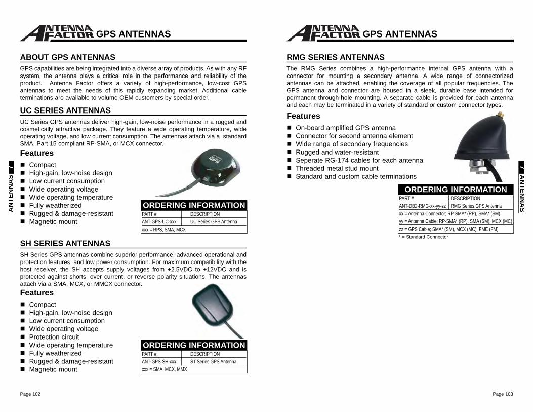
Page 103Page 102
GPS ANTENNAS
AN
TENN
AS
7
RMG SERIES ANTENNASThe RMG Series combines a high-performance internal GPS antenna with aconnector for mounting a secondary antenna. A wide range of connectorizedantennas can be attached, enabling the coverage of all popular frequencies. TheGPS antenna and connector are housed in a sleek, durable base intended forpermanent through-hole mounting. A separate cable is provided for each antennaand each may be terminated in a variety of standard or custom connector types.
PART # DESCRIPTIONANT-DB2-RMG-xx-yy-zz RMG Series GPS Antenna xx = Antenna Connector; RP-SMA* (RP), SMA* (SM)yy = Antenna Cable; RP-SMA* (RP), SMA (SM), MCX (MC)zz = GPS Cable; SMA* (SM), MCX (MC), FME (FM)
ORDERING INFORMATION
FeaturesOn-board amplified GPS antennaConnector for second antenna elementWide range of secondary frequenciesRugged and water-resistantSeperate RG-174 cables for each antennaThreaded metal stud mountStandard and custom cable terminations
* = Standard Connector
GPS ANTENNAS
ABOUT GPS ANTENNASGPS capabilities are being integrated into a diverse array of products. As with any RFsystem, the antenna plays a critical role in the performance and reliability of theproduct. Antenna Factor offers a variety of high-performance, low-cost GPSantennas to meet the needs of this rapidly expanding market. Additional cableterminations are available to volume OEM customers by special order.
UC SERIES ANTENNASUC Series GPS antennas deliver high-gain, low-noise performance in a rugged andcosmetically attractive package. They feature a wide operating temperature, wideoperating voltage, and low current consumption. The antennas attach via a standardSMA, Part 15 compliant RP-SMA, or MCX connector.Features
CompactHigh-gain, low-noise designLow current consumptionWide operating voltageWide operating temperatureFully weatherizedRugged & damage-resistantMagnetic mount
SH SERIES ANTENNASSH Series GPS antennas combine superior performance, advanced operational andprotection features, and low power consumption. For maximum compatibility with thehost receiver, the SH accepts supply voltages from +2.5VDC to +12VDC and isprotected against shorts, over current, or reverse polarity situations. The antennasattach via a SMA, MCX, or MMCX connector.Features
CompactHigh-gain, low-noise designLow current consumptionWide operating voltageProtection circuitWide operating temperatureFully weatherizedRugged & damage-resistantMagnetic mount
PART # DESCRIPTIONANT-GPS-UC-xxx UC Series GPS Antenna xxx = RPS, SMA, MCX
ORDERING INFORMATION
PART # DESCRIPTIONANT-GPS-SH-xxx ST Series GPS Antenna xxx = SMA, MCX, MMX
ORDERING INFORMATION
AN
TEN
NA
S7
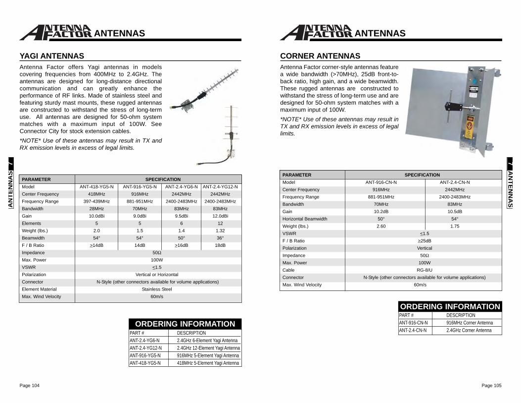
Page 105Page 104
CORNER ANTENNASAntenna Factor corner-style antennas featurea wide bandwidth (>70MHz), 25dB front-to-back ratio, high gain, and a wide beamwidth.These rugged antennas are constructed towithstand the stress of long-term use and aredesigned for 50-ohm system matches with amaximum input of 100W. *NOTE* Use of these antennas may result inTX and RX emission levels in excess of legallimits.
PARAMETER SPECIFICATIONModel ANT-916-CN-N ANT-2.4-CN-NCenter Frequency 916MHz 2442MHzFrequency Range 881-951MHz 2400-2483MHzBandwidth 70MHz 83MHzGain 10.2dB 10.5dBHorizontal Beamwidth 50° 54°Weight (lbs.) 2.60 1.75VSWR <1.5F / B Ratio >25dBPolarization VerticalImpedance 50ΩMax. Power 100WCable RG-8/UConnector N-Style (other connectors available for volume applications)Max. Wind Velocity 60m/s
PART # DESCRIPTION ANT-916-CN-N 916MHz Corner AntennaANT-2.4-CN-N 2.4GHz Corner Antenna
ORDERING INFORMATION
ANTENNAS
AN
TENN
AS
7
YAGI ANTENNASAntenna Factor offers Yagi antennas in modelscovering frequencies from 400MHz to 2.4GHz. Theantennas are designed for long-distance directionalcommunication and can greatly enhance theperformance of RF links. Made of stainless steel andfeaturing sturdy mast mounts, these rugged antennasare constructed to withstand the stress of long-termuse. All antennas are designed for 50-ohm systemmatches with a maximum input of 100W. SeeConnector City for stock extension cables.*NOTE* Use of these antennas may result in TX andRX emission levels in excess of legal limits.
PARAMETER SPECIFICATIONModel ANT-418-YG5-N ANT-916-YG5-N ANT-2.4-YG6-N ANT-2.4-YG12-NCenter Frequency 418MHz 916MHz 2442MHz 2442MHzFrequency Range 397-439MHz 881-951MHz 2400-2483MHz 2400-2483MHzBandwidth 28MHz 70MHz 83MHz 83MHzGain 10.0dBi 9.0dBi 9.5dBi 12.0dBiElements 5 5 6 12Weight (lbs.) 2.0 1.5 1.4 1.32Beamwidth 54° 54° 50° 36°F / B Ratio >14dB 14dB >16dB 18dBImpedance 50ΩMax. Power 100WVSWR <1.5Polarization Vertical or HorizontalConnector N-Style (other connectors available for volume applications)Element Material Stainless SteelMax. Wind Velocity 60m/s
PART # DESCRIPTION ANT-2.4-YG6-N 2.4GHz 6-Element Yagi AntennaANT-2.4-YG12-N 2.4GHz 12-Element Yagi AntennaANT-916-YG5-N 916MHz 5-Element Yagi AntennaANT-418-YG5-N 418MHz 5-Element Yagi Antenna
ORDERING INFORMATION
ANTENNAS
AN
TEN
NA
S7
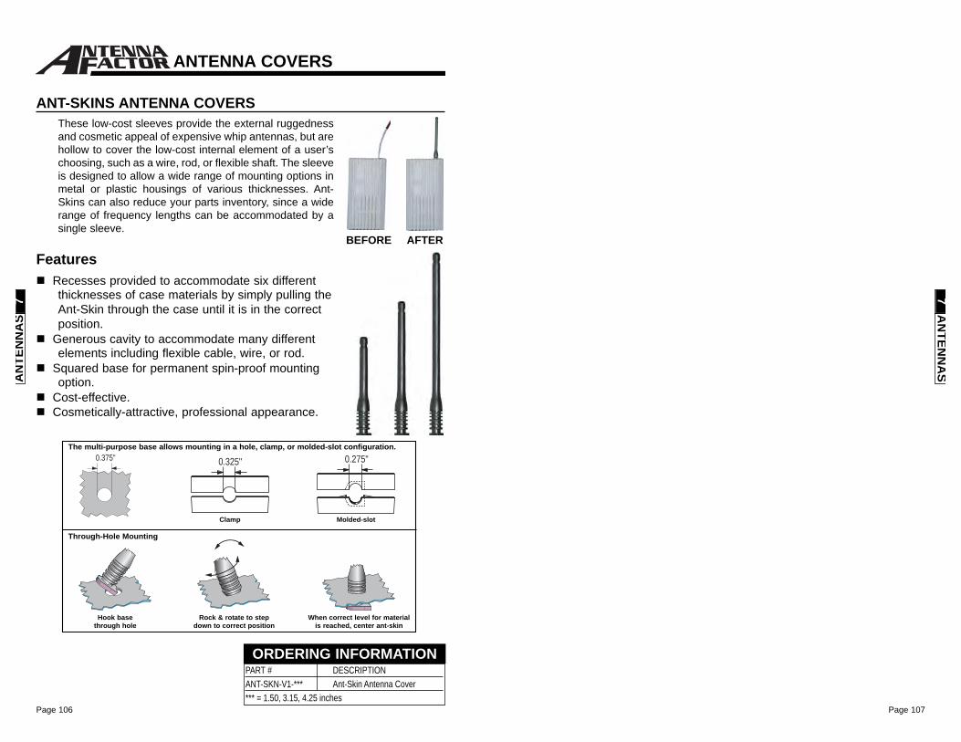
Page 107Page 106
AN
TENN
AS
7
PART # DESCRIPTIONANT-SKN-V1-*** Ant-Skin Antenna Cover*** = 1.50, 3.15, 4.25 inches
ORDERING INFORMATION
FeaturesRecesses provided to accommodate six differentthicknesses of case materials by simply pulling theAnt-Skin through the case until it is in the correctposition.
Generous cavity to accommodate many differentelements including flexible cable, wire, or rod.
Squared base for permanent spin-proof mountingoption.
Cost-effective.Cosmetically-attractive, professional appearance.
ANT-SKINS ANTENNA COVERSThese low-cost sleeves provide the external ruggednessand cosmetic appeal of expensive whip antennas, but arehollow to cover the low-cost internal element of a user’schoosing, such as a wire, rod, or flexible shaft. The sleeveis designed to allow a wide range of mounting options inmetal or plastic housings of various thicknesses. Ant-Skins can also reduce your parts inventory, since a widerange of frequency lengths can be accommodated by asingle sleeve.
BEFORE AFTER
The multi-purpose base allows mounting in a hole, clamp, or molded-slot configuration.
Through-Hole Mounting
Hook basethrough hole
Rock & rotate to step down to correct position
When correct level for materialis reached, center ant-skin
Molded-slotClamp
0.375" 0.325" 0.275"
ANTENNA COVERS
AN
TEN
NA
S7

Page 109
VISITwww.ConnectorCity.com
for a variety of additionalconnector options
Phone: (541) 956-0932Fax: (541) [email protected]
Welcome to the Products & Services of
About Connector CityConnector City focuses on cost-effective standard and custom RFconnectors designed for a wide range of consumer and industrialwireless products. Connector City has helped companies of allsizes meet the mechanical, electrical and aesthetic requirements oftheir wireless products.
Connector City stands apart from its competition by virtue of itsfocus on unique RF connector designs and FCC compliantconnectors. Examples of such products include connectors toovercome mounting and environmental challenges, Part 15compliant connectors that meet the unique restrictions of the FCC,and high-quality custom RF cable assemblies - all at verycompetitive prices. Connector City offers high quality custom RFcable assemblies, which can be designed online using thecompany's interactive cable designer. The division offers highlycompetitive prices relative to other established domestic suppliers.
By combining responsive customer service, individualized technicalsupport, world class quality, outstanding value and custom designcapabilities, Connector City hopes to be your connector supplier ofchoice.
Page 108
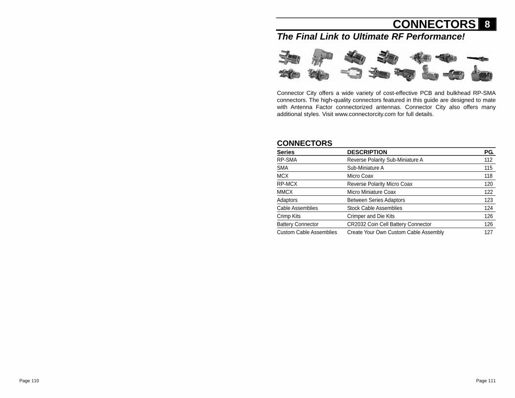
Page 111
The Final Link to Ultimate RF Performance!
CONNECTORSSeries DESCRIPTION PG.RP-SMA Reverse Polarity Sub-Miniature A 112SMA Sub-Miniature A 115MCX Micro Coax 118RP-MCX Reverse Polarity Micro Coax 120MMCX Micro Miniature Coax 122Adaptors Between Series Adaptors 123Cable Assemblies Stock Cable Assemblies 124Crimp Kits Crimper and Die Kits 126Battery Connector CR2032 Coin Cell Battery Connector 126Custom Cable Assemblies Create Your Own Custom Cable Assembly 127
CONNECTORS 8
Connector City offers a wide variety of cost-effective PCB and bulkhead RP-SMAconnectors. The high-quality connectors featured in this guide are designed to matewith Antenna Factor connectorized antennas. Connector City also offers manyadditional styles. Visit www.connectorcity.com for full details.
Page 110
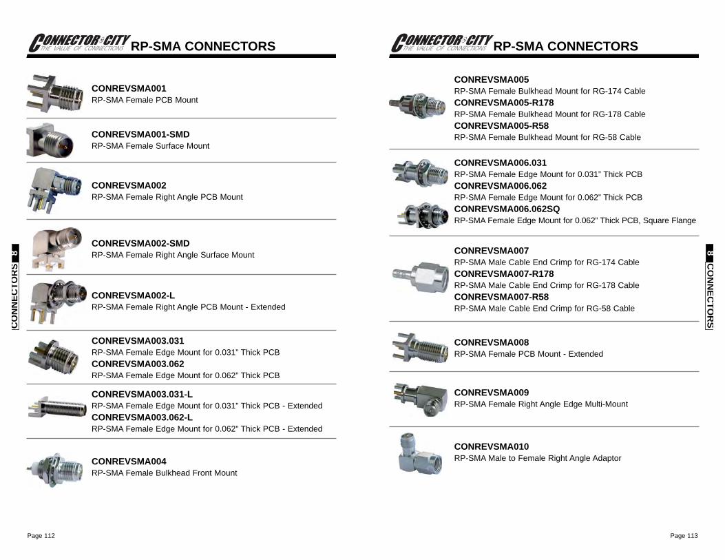
Page 113Page 112
CO
NN
ECTO
RS
8
RP-SMA CONNECTORS
CONREVSMA005RP-SMA Female Bulkhead Mount for RG-174 CableCONREVSMA005-R178RP-SMA Female Bulkhead Mount for RG-178 CableCONREVSMA005-R58RP-SMA Female Bulkhead Mount for RG-58 Cable
CONREVSMA006.031RP-SMA Female Edge Mount for 0.031” Thick PCBCONREVSMA006.062RP-SMA Female Edge Mount for 0.062” Thick PCBCONREVSMA006.062SQRP-SMA Female Edge Mount for 0.062” Thick PCB, Square Flange
CONREVSMA007RP-SMA Male Cable End Crimp for RG-174 CableCONREVSMA007-R178RP-SMA Male Cable End Crimp for RG-178 CableCONREVSMA007-R58RP-SMA Male Cable End Crimp for RG-58 Cable
CONREVSMA008RP-SMA Female PCB Mount - Extended
CONREVSMA009RP-SMA Female Right Angle Edge Multi-Mount
CONREVSMA010RP-SMA Male to Female Right Angle Adaptor
CONREVSMA001RP-SMA Female PCB Mount
RP-SMA CONNECTORS
CO
NN
ECTO
RS
8
CONREVSMA001-SMDRP-SMA Female Surface Mount
CONREVSMA002RP-SMA Female Right Angle PCB Mount
CONREVSMA002-SMDRP-SMA Female Right Angle Surface Mount
CONREVSMA002-LRP-SMA Female Right Angle PCB Mount - Extended
CONREVSMA003.031RP-SMA Female Edge Mount for 0.031” Thick PCBCONREVSMA003.062RP-SMA Female Edge Mount for 0.062” Thick PCB
CONREVSMA003.031-LRP-SMA Female Edge Mount for 0.031” Thick PCB - ExtendedCONREVSMA003.062-LRP-SMA Female Edge Mount for 0.062” Thick PCB - Extended
CONREVSMA004RP-SMA Female Bulkhead Front Mount
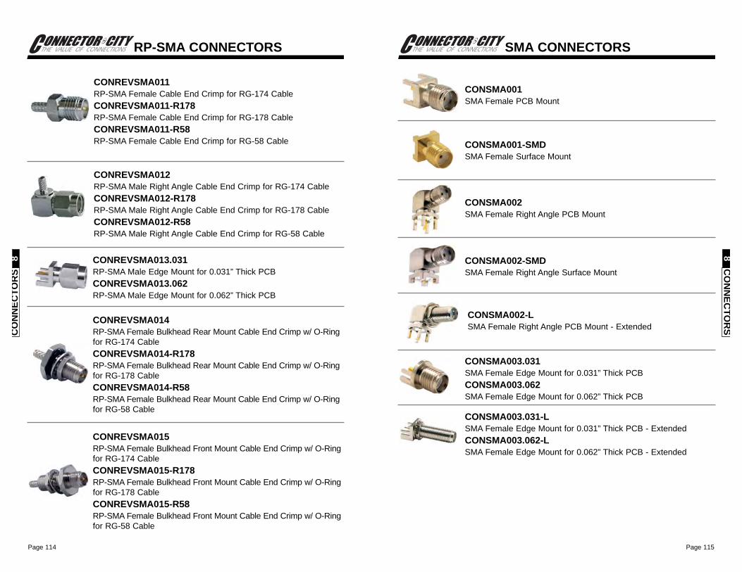
Page 115Page 114
SMA CONNECTORS
CO
NN
ECTO
RS
8
CONSMA001SMA Female PCB Mount
CONSMA001-SMDSMA Female Surface Mount
CONSMA002SMA Female Right Angle PCB Mount
CONSMA002-SMDSMA Female Right Angle Surface Mount
CONSMA002-LSMA Female Right Angle PCB Mount - Extended
CONSMA003.031SMA Female Edge Mount for 0.031” Thick PCBCONSMA003.062SMA Female Edge Mount for 0.062” Thick PCB
CONSMA003.031-LSMA Female Edge Mount for 0.031” Thick PCB - ExtendedCONSMA003.062-LSMA Female Edge Mount for 0.062” Thick PCB - Extended
RP-SMA CONNECTORS
CO
NN
ECTO
RS
8
CONREVSMA011RP-SMA Female Cable End Crimp for RG-174 CableCONREVSMA011-R178RP-SMA Female Cable End Crimp for RG-178 CableCONREVSMA011-R58RP-SMA Female Cable End Crimp for RG-58 Cable
CONREVSMA012RP-SMA Male Right Angle Cable End Crimp for RG-174 CableCONREVSMA012-R178RP-SMA Male Right Angle Cable End Crimp for RG-178 CableCONREVSMA012-R58RP-SMA Male Right Angle Cable End Crimp for RG-58 Cable
CONREVSMA013.031RP-SMA Male Edge Mount for 0.031” Thick PCBCONREVSMA013.062RP-SMA Male Edge Mount for 0.062” Thick PCB
CONREVSMA014RP-SMA Female Bulkhead Rear Mount Cable End Crimp w/ O-Ringfor RG-174 CableCONREVSMA014-R178RP-SMA Female Bulkhead Rear Mount Cable End Crimp w/ O-Ringfor RG-178 CableCONREVSMA014-R58RP-SMA Female Bulkhead Rear Mount Cable End Crimp w/ O-Ringfor RG-58 Cable
CONREVSMA015RP-SMA Female Bulkhead Front Mount Cable End Crimp w/ O-Ringfor RG-174 CableCONREVSMA015-R178RP-SMA Female Bulkhead Front Mount Cable End Crimp w/ O-Ringfor RG-178 CableCONREVSMA015-R58RP-SMA Female Bulkhead Front Mount Cable End Crimp w/ O-Ringfor RG-58 Cable
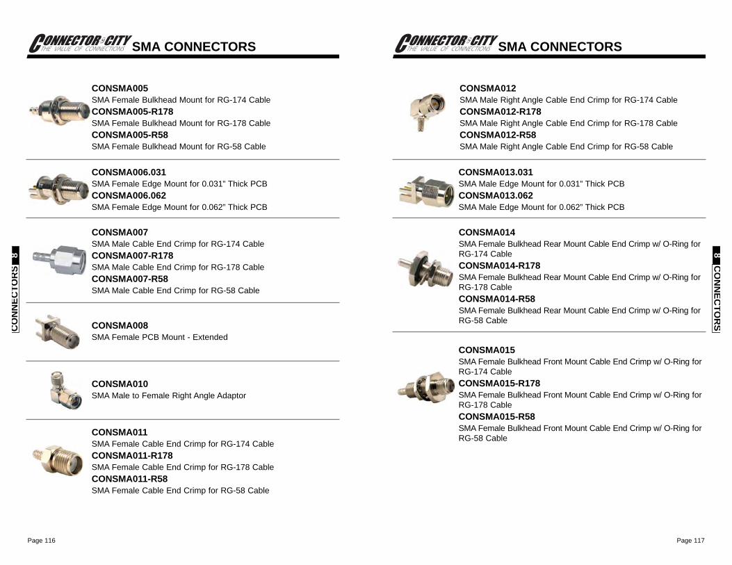
Page 117Page 116
SMA CONNECTORS
CO
NN
ECTO
RS
8
CONSMA012SMA Male Right Angle Cable End Crimp for RG-174 CableCONSMA012-R178SMA Male Right Angle Cable End Crimp for RG-178 CableCONSMA012-R58SMA Male Right Angle Cable End Crimp for RG-58 Cable
CONSMA013.031SMA Male Edge Mount for 0.031” Thick PCBCONSMA013.062SMA Male Edge Mount for 0.062” Thick PCB
CONSMA014SMA Female Bulkhead Rear Mount Cable End Crimp w/ O-Ring forRG-174 CableCONSMA014-R178SMA Female Bulkhead Rear Mount Cable End Crimp w/ O-Ring forRG-178 CableCONSMA014-R58SMA Female Bulkhead Rear Mount Cable End Crimp w/ O-Ring forRG-58 Cable
CONSMA015SMA Female Bulkhead Front Mount Cable End Crimp w/ O-Ring forRG-174 CableCONSMA015-R178SMA Female Bulkhead Front Mount Cable End Crimp w/ O-Ring forRG-178 CableCONSMA015-R58SMA Female Bulkhead Front Mount Cable End Crimp w/ O-Ring forRG-58 Cable
SMA CONNECTORS
CO
NN
ECTO
RS
8
CONSMA005SMA Female Bulkhead Mount for RG-174 CableCONSMA005-R178SMA Female Bulkhead Mount for RG-178 CableCONSMA005-R58SMA Female Bulkhead Mount for RG-58 Cable
CONSMA006.031SMA Female Edge Mount for 0.031” Thick PCBCONSMA006.062SMA Female Edge Mount for 0.062” Thick PCB
CONSMA007SMA Male Cable End Crimp for RG-174 CableCONSMA007-R178SMA Male Cable End Crimp for RG-178 CableCONSMA007-R58SMA Male Cable End Crimp for RG-58 Cable
CONSMA008SMA Female PCB Mount - Extended
CONSMA010SMA Male to Female Right Angle Adaptor
CONSMA011SMA Female Cable End Crimp for RG-174 CableCONSMA011-R178SMA Female Cable End Crimp for RG-178 CableCONSMA011-R58SMA Female Cable End Crimp for RG-58 Cable
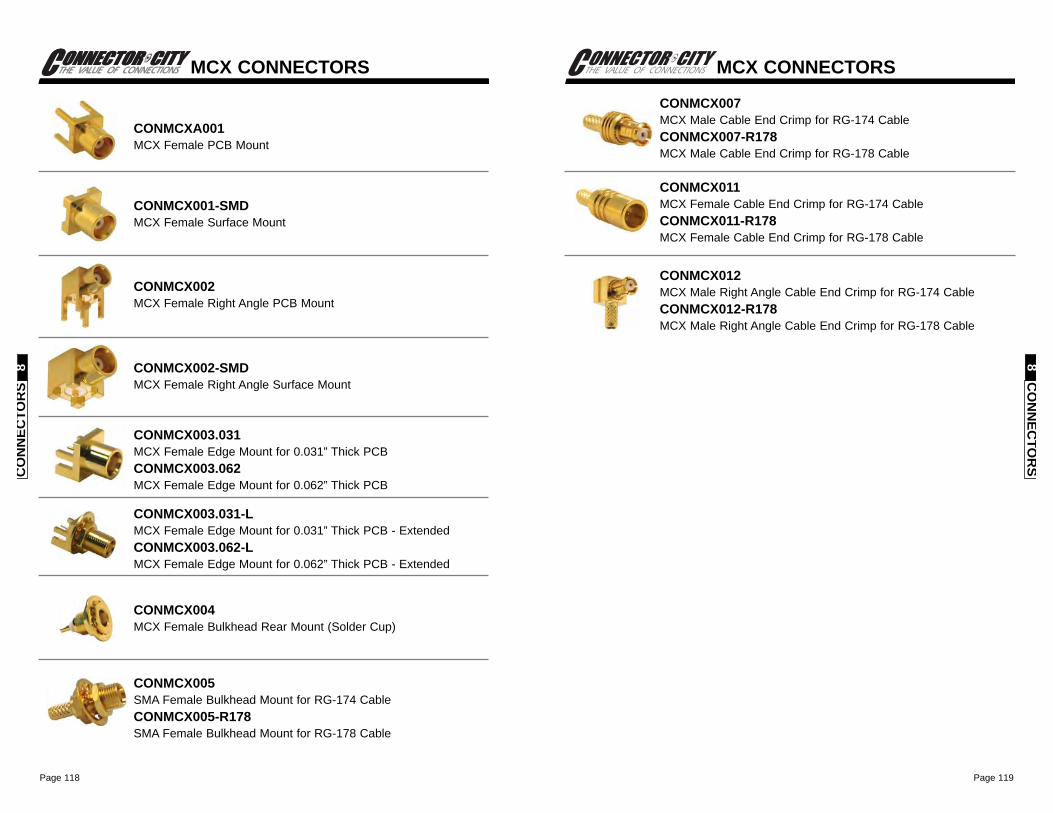
Page 119Page 118
CO
NN
ECTO
RS
8
MCX CONNECTORS
CONMCX007MCX Male Cable End Crimp for RG-174 CableCONMCX007-R178MCX Male Cable End Crimp for RG-178 Cable
CONMCX011MCX Female Cable End Crimp for RG-174 CableCONMCX011-R178MCX Female Cable End Crimp for RG-178 Cable
CONMCX012MCX Male Right Angle Cable End Crimp for RG-174 CableCONMCX012-R178MCX Male Right Angle Cable End Crimp for RG-178 Cable
CO
NN
ECTO
RS
8
MCX CONNECTORS
CONMCXA001MCX Female PCB Mount
CONMCX001-SMDMCX Female Surface Mount
CONMCX002MCX Female Right Angle PCB Mount
CONMCX002-SMDMCX Female Right Angle Surface Mount
CONMCX003.031MCX Female Edge Mount for 0.031” Thick PCBCONMCX003.062MCX Female Edge Mount for 0.062” Thick PCB
CONMCX003.031-LMCX Female Edge Mount for 0.031” Thick PCB - ExtendedCONMCX003.062-LMCX Female Edge Mount for 0.062” Thick PCB - Extended
CONMCX004MCX Female Bulkhead Rear Mount (Solder Cup)
CONMCX005SMA Female Bulkhead Mount for RG-174 CableCONMCX005-R178SMA Female Bulkhead Mount for RG-178 Cable
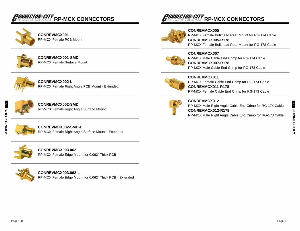
Page 121Page 120
CO
NN
ECTO
RS
8
RP-MCX CONNECTORS
CONREVMCX005RP-MCX Female Bulkhead Rear Mount for RG-174 CableCONREVMCX005-R178RP-MCX Female Bulkhead Rear Mount for RG-178 Cable
CONREVMCX007RP-MCX Male Cable End Crimp for RG-174 CableCONREVMCX007-R178RP-MCX Male Cable End Crimp for RG-178 Cable
CONREVMCX011RP-MCX Female Cable End Crimp for RG-174 CableCONREVMCX011-R178RP-MCX Female Cable End Crimp for RG-178 Cable
CONREVMCX012RP-MCX Male Right Angle Cable End Crimp for RG-174 CableCONREVMCX012-R178RP-MCX Male Right Angle Cable End Crimp for RG-178 Cable
CO
NN
ECTO
RS
8
RP-MCX CONNECTORS
CONREVMCX001RP-MCX Female PCB Mount
CONREVMCX001-SMDRP-MCX Female Surface Mount
CONREVMCX002-LRP-MCX Female Right Angle PCB Mount - Extended
CONREVMCX002-SMDRP-MCX Female Right Angle Surface Mount
CONREVMCX002-SMD-LRP-MCX Female Right Angle Surface Mount - Extended
CONREVMCX003.062RP-MCX Female Edge Mount for 0.062” Thick PCB
CONREVMCX003.062-LRP-MCX Female Edge Mount for 0.062” Thick PCB - Extended
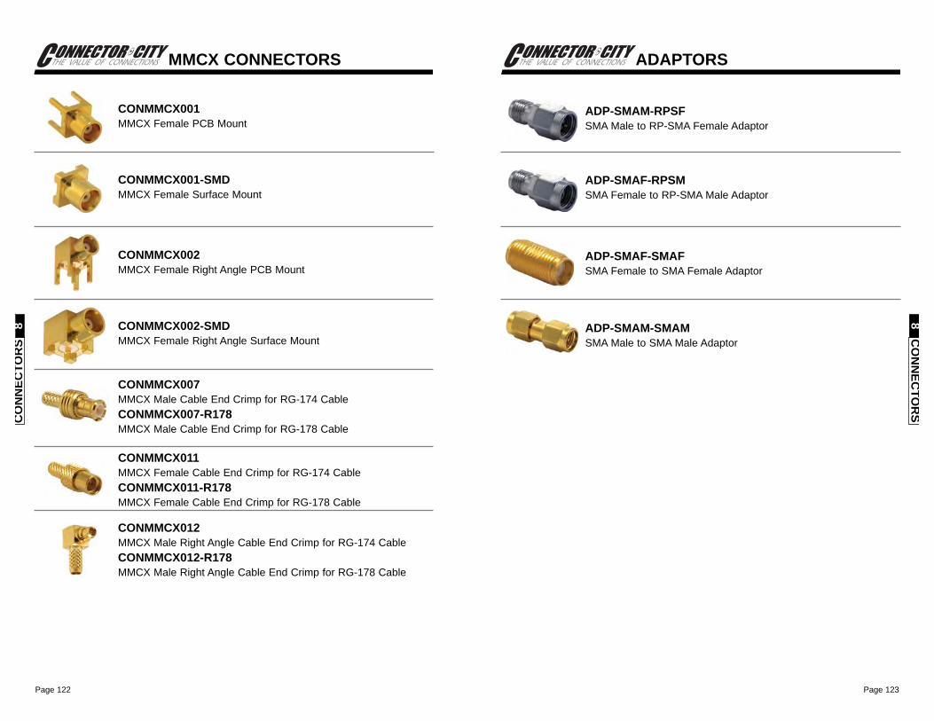
Page 123Page 122
CO
NN
ECTO
RS
8
ADAPTORS
ADP-SMAM-RPSFSMA Male to RP-SMA Female Adaptor
ADP-SMAF-RPSMSMA Female to RP-SMA Male Adaptor
ADP-SMAF-SMAFSMA Female to SMA Female Adaptor
ADP-SMAM-SMAMSMA Male to SMA Male Adaptor
CO
NN
ECTO
RS
8
MMCX CONNECTORS
CONMMCX001MMCX Female PCB Mount
CONMMCX001-SMDMMCX Female Surface Mount
CONMMCX002MMCX Female Right Angle PCB Mount
CONMMCX002-SMDMMCX Female Right Angle Surface Mount
CONMMCX007MMCX Male Cable End Crimp for RG-174 CableCONMMCX007-R178MMCX Male Cable End Crimp for RG-178 Cable
CONMMCX011MMCX Female Cable End Crimp for RG-174 CableCONMMCX011-R178MMCX Female Cable End Crimp for RG-178 Cable
CONMMCX012MMCX Male Right Angle Cable End Crimp for RG-174 CableCONMMCX012-R178MMCX Male Right Angle Cable End Crimp for RG-178 Cable
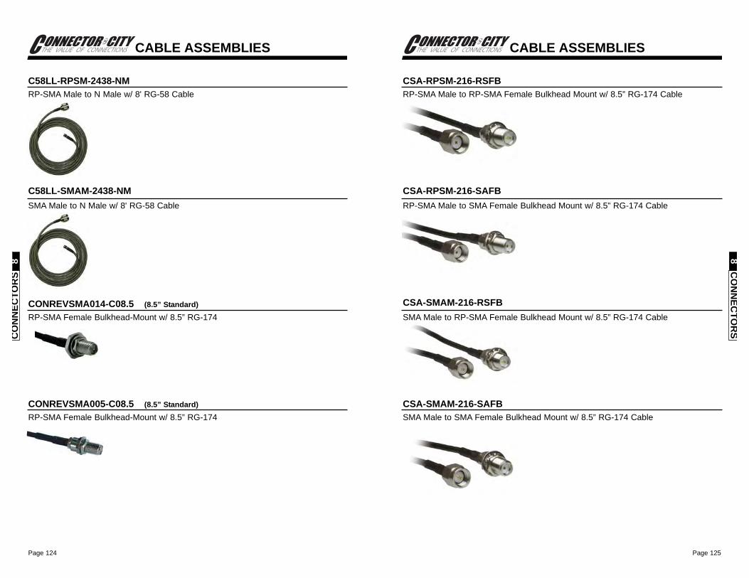
Page 125Page 124
CABLE ASSEMBLIES
CO
NN
ECTO
RS
8
CSA-RPSM-216-RSFBRP-SMA Male to RP-SMA Female Bulkhead Mount w/ 8.5” RG-174 Cable
CSA-RPSM-216-SAFBRP-SMA Male to SMA Female Bulkhead Mount w/ 8.5” RG-174 Cable
CSA-SMAM-216-RSFBSMA Male to RP-SMA Female Bulkhead Mount w/ 8.5” RG-174 Cable
CSA-SMAM-216-SAFBSMA Male to SMA Female Bulkhead Mount w/ 8.5” RG-174 Cable
CO
NN
ECTO
RS
8
CABLE ASSEMBLIES
C58LL-RPSM-2438-NMRP-SMA Male to N Male w/ 8' RG-58 Cable
C58LL-SMAM-2438-NMSMA Male to N Male w/ 8' RG-58 Cable
CONREVSMA014-C08.5 (8.5” Standard)RP-SMA Female Bulkhead-Mount w/ 8.5” RG-174
CONREVSMA005-C08.5 (8.5” Standard)RP-SMA Female Bulkhead-Mount w/ 8.5” RG-174
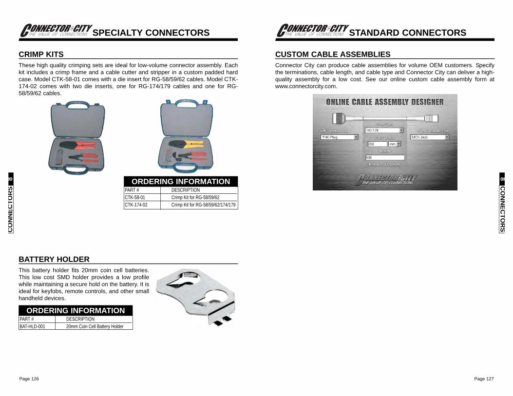
Page 127Page 126
STANDARD CONNECTORS
CO
NN
ECTO
RS
8
CUSTOM CABLE ASSEMBLIESConnector City can produce cable assemblies for volume OEM customers. Specifythe terminations, cable length, and cable type and Connector City can deliver a high-quality assembly for a low cost. See our online custom cable assembly form atwww.connectorcity.com.
SPECIALTY CONNECTORS
CO
NN
ECTO
RS
8
CRIMP KITSThese high quality crimping sets are ideal for low-volume connector assembly. Eachkit includes a crimp frame and a cable cutter and stripper in a custom padded hardcase. Model CTK-58-01 comes with a die insert for RG-58/59/62 cables. Model CTK-174-02 comes with two die inserts, one for RG-174/179 cables and one for RG-58/59/62 cables.
PART # DESCRIPTION CTK-58-01 Crimp Kit for RG-58/59/62CTK-174-02 Crimp Kit for RG-58/59/62/174/179
ORDERING INFORMATION
BATTERY HOLDERThis battery holder fits 20mm coin cell batteries.This low cost SMD holder provides a low profilewhile maintaining a secure hold on the battery. It isideal for keyfobs, remote controls, and other smallhandheld devices.
PART # DESCRIPTION BAT-HLD-001 20mm Coin Cell Battery Holder
ORDERING INFORMATION

Page 129Page 128
ADDITIONAL SERVICES 9
An engineer will generally choose most components based on technical issues offunction and application. RF products are unusual in that they involve not only suchtechnical issues, but issues of legality as well. Many manufacturers have avoidedincorporating RF into their products as a result of uncertainty and even fear of suchmatters.In order to address these concerns and simplify each customer’s design cycle, Linxhas attempted to identify any step in the RF implementation process that may causedelay or frustration. We have tailored a service to simplify that step. While suchservices are unusual for a high-volume component manufacturer, they are all a partof the Linx commitment to “Wireless Made Simple”.
Helping You Bring Your Product To Life

Page 131
WIRELESS MADE SIMPLE ®
Page 130
WIRELESS MADE SIMPLE ®
INTERNET SITEIf you have questions regardingany Linx product and have internetaccess, makewww.linxtechnologies.com your first stop. Our website isorganized in an intuitive format togive you the answers you need inrecord time. Day or night, the Linxwebsite gives you instant accessto the latest information regardingthe products and services of Linx.It’s all here: manual and software updates, application notes, FCC information,and much more. Be sure to visit soon!
IMPLEMENTATION ASSISTANCEWhile Linx does not undertake OEM designprojects, in most instances, our engineers havebroad experience in almost every area of designand manufacturing. Linx is pleased to offer ourcustomers the benefit of that experience as itpertains to the integration of Linx RF productsinto a product design.
EDUCATIONAt Linx, we believe that our best customer is aninformed customer. That is why our comprehensivemanuals are supported by a growing library ofinformative Application Notes. These notes aredesigned to provide guidance on the effectiveimplementation of Linx products across a broadrange of applications. Many different topics arediscussed in more detail than in the device dataguide, from matters to consider before embarkingon a design to complete overviews of legal and technical issues affectingwireless products. Backed by the assistance of experienced support personnel,each customer has an opportunity to learn about our products and the basicprinciples of RF whereby they work. Application Notes may be downloaded fromwww.linxtechnologies.com or obtained by contacting the Linx literaturedepartment.
AD
DITIO
NA
LSER
VICES
9
ADDITIONAL SERVICES
FCC PRE-SCREEN SERVICESThe most difficult obstacle to overcomewhen bringing an RF-based product tomarket, aside from the design itself, isthe approval process. To ensure ourcustomers the best opportunity to passFCC testing, Linx offers unique low-costpre-compliance testing services. Usingour state-of-the-art Hewlett PackardEMC compliancy test system, a productis screened just as it will be duringactual FCC testing. In addition to thisscreen, the actual design is evaluatedby a Linx engineer to ensure that it isboth legal and technically optimized. A pre-screen report is then generatedsummarizing our findings and recommendations. This report, along withadditional documentation, will ease your preparations for final approval testing.
OEM MODIFICATIONSAs a rule, Linx does not undertake the design ormanufacture of customer-specific products; however, manyproducts can be modified for high-volume applications. OurOEM product lines are especially suited to suchmodifications. Company logos, custom colors, andnomenclature are all ways that Linx products can beadapted to meet the needs of an individual customer.Custom antennas, cables, and connectors can also beprovided through Linx’s Antenna Factor and Connector Citydivisions.
ANTENNA DESIGN ASSISTANCELinx offers a wide variety of standard antenna styles thatwill meet the needs of most user applications.Occasionally a design will call for a custom antenna tomeet physical or cosmetic constraints. Since the designof application-specific antennas calls for experience andequipment outside the scope of many of our customers,Linx offers antenna design services. These servicesrange from assistance in evaluation of a customer’santenna configuration to actual antenna design. One ofour most popular design specialties is small printedantennas that are often incorporated directly on a PCBto reduce cost and eliminate a visible antenna.
ADDITIONAL SERVICES
AD
DIT
ION
AL
SER
VIC
ES9
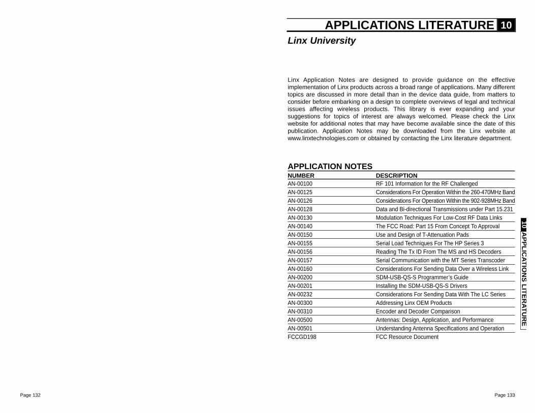
Page 133Page 132
Linx Application Notes are designed to provide guidance on the effectiveimplementation of Linx products across a broad range of applications. Many differenttopics are discussed in more detail than in the device data guide, from matters toconsider before embarking on a design to complete overviews of legal and technicalissues affecting wireless products. This library is ever expanding and yoursuggestions for topics of interest are always welcomed. Please check the Linxwebsite for additional notes that may have become available since the date of thispublication. Application Notes may be downloaded from the Linx website atwww.linxtechnologies.com or obtained by contacting the Linx literature department.
APPLICATIONS LITERATURE 10
APPLICATION NOTESNUMBER DESCRIPTIONAN-00100 RF 101 Information for the RF ChallengedAN-00125 Considerations For Operation Within the 260-470MHz BandAN-00126 Considerations For Operation Within the 902-928MHz BandAN-00128 Data and Bi-directional Transmissions under Part 15.231AN-00130 Modulation Techniques For Low-Cost RF Data LinksAN-00140 The FCC Road: Part 15 From Concept To ApprovalAN-00150 Use and Design of T-Attenuation PadsAN-00155 Serial Load Techniques For The HP Series 3AN-00156 Reading The Tx ID From The MS and HS DecodersAN-00157 Serial Communication with the MT Series TranscoderAN-00160 Considerations For Sending Data Over a Wireless LinkAN-00200 SDM-USB-QS-S Programmer’s GuideAN-00201 Installing the SDM-USB-QS-S DriversAN-00232 Considerations For Sending Data With The LC SeriesAN-00300 Addressing Linx OEM ProductsAN-00310 Encoder and Decoder ComparisonAN-00500 Antennas: Design, Application, and PerformanceAN-00501 Understanding Antenna Specifications and OperationFCCGD198 FCC Resource Document
Linx University
APPLIC
ATION
S LITERATU
RE
10
Page 135
WIRELESS MADE SIMPLE ®
Page 134
11. CUSTOMER'S REMEDIESIn the event warranty service is required, an RMA# must be obtained from Linx prior to return. Linx willcarefully assess Customer's returned Product. If it is found to qualify for warranty status, Linx will, at itselection, repair or replace the Product without charge (excluding inbound shipping), or refund the originalpurchase price paid.12. LIMITATIONS ON CUSTOMER'S REMEDIESIN NO EVENT SHALL LINX BE LIABLE FOR ANY OF CUSTOMER'S INCIDENTIAL OR CONSEQUENTIALDAMAGES, INCLUDING, WITHOUT LIMITATION, ANY LOST PROFITS OR LOST REVENUES, ARISING INANY WAY FROM ANY DEFECTIVE OR NON-CONFORMING PRODUCTS OR FOR ANY OTHER BREACH OFCONTRACT BY LINX. The limitations on Linx's liability is applicable to any and all claims or theories ofrecovery asserted by Customer, including, without limitation, breach of contract, breach of warranty, strictliability, or negligence. Customer assumes all liability (including, without limitation, liability for injury toperson or property, economic loss, or business interruption) for all claims, including claims from third parties,arising from the use of the Products.13. LIMITATIONS ON TIME TO BRING ACTIONAny action by Customer against Linx must be commenced by Customer within one year after the cause ofaction has accrued.14. LINX'S REMEDIESUpon default by Customer, Linx shall have all the remedies afforded a seller of goods at law or in equity, including,without limitation, the right to (a) immediately accelerate all amounts due from Customer, (b) suspendshipment of all Products ordered, and (c) cancel all orders for Products.15. INDEMNITYCustomer will indemnify, defend, protect, and hold harmless Linx from and against all claims, damages,actions, suits, proceedings, demands, assessments, adjustments, costs, and expenses incurred by Linx asa result of or arising from any Products sold by Linx to Customer.16. FCC CERTIFICATIONLinx designs its Products taking into account compliance with FCC Part 15. HOWEVER, IT IS THE SOLERESPONSIBILITY OF CUSTOMER TO VERIFY THE APPROPRIATENESS OF THE PRODUCTS FOR EACHINDIVIDUAL APPLICATION AND OBTAIN CERTIFICATION OF THE CUSTOMER'S COMPLETED GOODS INTOWHICH THE PRODUCTS ARE INCORPORATED.17. PROPRIETARY INFORMATIONLinx's Products may contain proprietary, patented, or copyrighted techniques, components, or materials.Under no circumstances shall any Customer have any right, title, or interest in any of Linx's proprietaryinformation.18. DELAYS AND FORCE MAJEURELinx shall not be in default for any delay in performance or delivery caused by circumstances beyond itsreasonable control, including, but not limited to, an act of God, fires, floods, wars, terror, government actions,accidents, labor troubles, labor shortages, unavailability of materials, unavailability of equipment, or unavailabilityof transportation ("Force Majeure Event"). Linx may, without liability to Customer, suspend or cancel itsperformance upon the occurrence of any Force Majeure Event without liability to Customer.19. COMPLETE AGREEMENTThese Terms and Conditions may be changed only by a written document executed by Linx and Customer.Any order, acknowledgment, or other form of acceptance issued by Customer that modifies, conflicts with,or contradicts any provision of these Terms and Conditions is objected to and rejected by Linx.20. CHOICE OF LAWThe parties' agreement shall be governed by the laws of the State of Oregon. For international sales, the lawsof the State of Oregon, and not the United Nations Convention on Contracts for the International Sales of Goods,shall apply.21. ARBITRATION AND ATTORNEY FEESAny and all claims arising under these Terms and Conditions, or arising in any way from the sale or use ofthe Products, or otherwise, shall be resolved by binding, mandatory arbitration under the authority of theArbitration Service of Portland before a panel of three arbitrators. The arbitration shall be conducted inPortland, OR. The prevailing party in the arbitration shall be entitled to an award of attorney fees and all othercosts of arbitration against the non-prevailing party.
SALES PO
LICIES
11
TERMS AND CONDITIONS OF SALE 111. PAYMENT TERMS Customer shall pay Linx in advance for all evaluation kits and orders for less than 1,000 pieces of Product.Customer shall pay all other orders for Product without setoff or deduction upon receipt of Linx's invoice,unless prior credit approval has been granted by Linx. Linx may extend NET 30 terms on approved accounts.Please complete Linx's credit application for consideration of NET 30 terms. All prices quoted or charged byLinx shall be F.O.B. Linx's plant. Prices do not include sales, excise, use, or other taxes measured by the salesprice of Product sold. Customer shall pay any and all such taxes. Interest shall accrue on all past due amountsat the rate of 1.5% per month or the maximum allowed by law, whichever is less.2. QUANTITY DISCOUNTSLinx may, in its discretion, extend quantity pricing discounts to Customers with accounts in good standing basedon the amount of Product purchased in a six-month period with up to four Product release dates. In the eventof rescheduling or partial cancellations, Linx will retroactively invoice Customer to reflect the discount attributablefor the actual amount of Product accepted.3. EVALUATION KIT PURCHASE REQUIREMENTLinx requires the Customer to purchase an evaluation kit prior to the sale of individual modules of Product.This policy ensures that each Customer has the tools necessary to fairly evaluate our Products and legally usethem for Customer's application.4. CANCELLATIONSCustomer may cancel an order for standard Product at any time prior to shipment by Linx. If the cancellationaffects a quantity discount extended for a blanket order, Customer will be billed retroactively for the differencebetween the quantity of Product ordered and quantity accepted. Cancellation of an order for custom Productat any time or standard Product after shipment is not permitted.5. CHANGESLinx realizes Customer's needs change rapidly and will attempt to accommodate requested changes toCustomer's orders. Additional charges for requested changes may apply.6. DELIVERYLinx will deliver the Products by placing them with a carrier for delivery to Customer. Delivery dates areestimated only. In no event shall Linx be liable to Customer or any third parties for any damages of any kind,direct or indirect, in the event of delay of delivery.7. INSPECTION AND ACCEPTANCECustomer shall promptly inspect and test all Products upon receipt. Customer shall be deemed to have acceptedall Products unless Customer gives written notice of defective or non-conforming Products within 15 days afterreceipt. Customer's notice shall describe the defect or non-conformity of the Products. Repair or replacementof any Products Linx determines to be defective or non-conforming shall be in accordance with Linx's LimitedWarranty and Exclusions and Customer's Remedies as provided for below.8. RETURNSAll Product returned to Linx must be accompanied by a valid Return Merchandise Authorization Number("RMA#"), which may be obtained by calling our Customer Service Department at (541) 471-6256. Productsnot bearing an RMA# will be returned at Customer's expense. Customer may return for refund or credit new,unused, non-defective, or conforming Products that were shipped within the prior 120 days subject to (a) a15% restocking charge, or (b) no restocking charge when the return is accompanied by a new order for Productthat is at least twice the invoice amount (freight, insurance, and taxes excluded) of the returned Product.9. LIMITED WARRANTY AND EXCLUSIONSLinx warrants that its Products will conform to Linx's current published specifications and be free of defectsin materials and workmanship for 90 days from the date of purchase when used in accordance with theguidelines and parameters specified by Linx's documentation. Linx does not warrant against defects arisingfrom improper design, application, or assembly practices, rework damage, exposure to moisture, impacts,excessive heat or cold, ESD, or overvoltage, or any other condition resulting from other than ordinary andappropriate usage.Linx does not warrant the suitability of its Products for any specific application by Customer. NNOONNEE OOFF LLIINNXX''SSPPRROODDUUCCTTSS IISS IINNTTEENNDDEEDD FFOORR UUSSEE IINN AAPPPPLLIICCAATTIIOONNSS IINN WWHHIICCHH TTHHEE SSAAFFEETTYY OOFF LLIIFFEE OORR PPRROOPPEERRTTYY IISS AATTRRIISSKK.. Linx does not warrant any of its Products used in any application in which life or property is at risk.10. DISCLAIMER OF OTHER WARRANTIESLINX DISCLAIMS ALL WARRANTIES OF MERCHANTABILITY AND FITNESS FOR A PARTICULAR PURPOSE.
TERMS AND CONDITIONS OF SALE 11SA
LES
POLI
CIE
S11

Page 136
Page 138