Embed Size (px)
Citation preview
Converged Plantwide Ethernet (CPw
OL-21226-01, ENET-TD001E-EN-P
C H A P T E R 2
Converged Plantwide Ethernet SolutionOverviewThis chapter provides an overview of the Converged Plantwide Ethernet (CPwE) solution architecture, which describes the various systems, components, and their relation to each other to provide context to the networking function and technical requirements. The CPwE solution is designed for industrial Ethernet applications. Although CPwE solution is applicable to multiple industries, this Design and Implementation Guide (DIG) focuses on the manufacturing industry. CPwE is an architecture that provides network and security services to the devices, equipment, and applications found in an Industrial Automation and Control System (IACS), and integrates them into the enterprise-wide network. The networking requirements of an IACS often differ from a typical IT network. This CPwE solution architecture overview provides the background and description of an IACS network model and highlights the differences between the CPwE architecture and a typical enterprise network.
Reuse is an objective of any architecture and is the case with the CPwE solution architecture. An IACS is deployed in a wide variety of industries such as automotive, pharmaceuticals, consumer goods, pulp and paper, oil and gas, and energy. IACS applications are also deployed in a wide variety of manufacturing disciplines such as batch, discrete, process, and hybrid manufacturing. Size of deployments include small (less than 50 network infrastructure devices), medium (less than 200 network infrastructure devices), and large (from 200 up to greater than 10,000 network infrastructure devices). This architecture is meant to be a model/structure to be used in all these types of manufacturing environments, but clearly it must be tailored to the industry, type of manufacturing discipline, size, and eventually the manufacturer's standards.
Industrial Automation and Control System Reference Model
To understand the security and network systems requirements of an IACS, this DIG uses a logical framework to describe the basic functions and composition of a manufacturing system. The Purdue Model for Control Hierarchy (reference ISBN 1-55617-265-6) is a common and well-understood model in the manufacturing industry that segments devices and equipment into hierarchical functions. It has been incorporated into many other models and standards in the industry. Based on this segmentation of the plant technology, the International Society of Automation ISA-99
2-1E) Design and Implementation Guide
Chapter 2 Converged Plantwide Ethernet Solution
Industrial Automation and Control System Reference Model
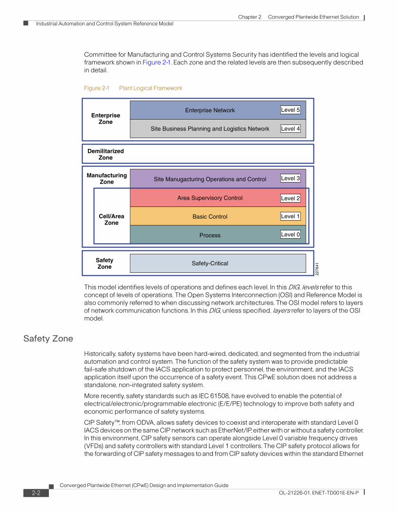
Committee for Manufacturing and Control Systems Security has identified the levels and logical framework shown in Figure 2-1. Each zone and the related levels are then subsequently described in detail.
Figure 2-1 Plant Logical Framework
This model identifies levels of operations and defines each level. In this DIG, levels refer to this concept of levels of operations. The Open Systems Interconnection (OSI) and Reference Model is also commonly referred to when discussing network architectures. The OSI model refers to layers of network communication functions. In this DIG, unless specified, layers refer to layers of the OSI model.
Safety Zone
Historically, safety systems have been hard-wired, dedicated, and segmented from the industrial automation and control system. The function of the safety system was to provide predictable fail-safe shutdown of the IACS application to protect personnel, the environment, and the IACS application itself upon the occurrence of a safety event. This CPwE solution does not address a standalone, non-integrated safety system.
More recently, safety standards such as IEC 61508, have evolved to enable the potential of electrical/electronic/programmable electronic (E/E/PE) technology to improve both safety and economic performance of safety systems.
CIP Safety™, from ODVA, allows safety devices to coexist and interoperate with standard Level 0 IACS devices on the same CIP network such as EtherNet/IP, either with or without a safety controller. In this environment, CIP safety sensors can operate alongside Level 0 variable frequency drives (VFDs) and safety controllers with standard Level 1 controllers. The CIP safety protocol allows for the forwarding of CIP safety messages to and from CIP safety devices within the standard Ethernet
SafetyZone Safety-Critical
DemilitarizedZone
ManufacturingZone
Cell/AreaZone
Site Manugacturing Operations and Control
Area Supervisory Control
Basic Control
Process
2276
41
Enterprise Network
Site Business Planning and Logistics Network
EnterpriseZone
Level 5
Level 4
Level 3
Level 1
Level 0
Level 2
2-2Converged Plantwide Ethernet (CPwE) Design and Implementation Guide
OL-21226-01, ENET-TD001E-EN-P
Chapter 2 Converged Plantwide Ethernet Solution
Industrial Automation and Control System Reference Model
and IP network switching infrastructure. The CIP safety protocol is an endnode-to-endnode safety protocol. If CIP safety messages are interrupted, the CIP safety devices fail-safe. The integrity of the safety control loop is not affected by a disruption in the standard network infrastructure.
CIP safety helps manufacturers to maximize uptime by coordinating the safe and standard functions of equipment. CIP safety also allows the distribution of safety control devices to appropriate locations within an IACS application, thereby helping to reduce overall installation costs. The ability to implement safety control within a single IACS network, such as EtherNet/IP, offers many advantages over hardwiring, including reduced design, installation, and maintenance costs, as well as expanded diagnostic capabilities.
Although CIP safety devices residing on EtherNet/IP can coexist with IACS network devices within Levels 0 and 1, specific considerations for applying safety control using CIP safety devices are not directly addressed within this version of the CPwE solution.
Cell/Area Zone
The Cell/Area zone is a functional area within a plant facility; many plants have multiple Cell/Area zones. In an automotive plant, it may be a bodyshop or a sub-assembly process. In a food and beverage facility, it may be the batch mixing area. It may be as small as a single controller and its associated devices on a process skid, or multiple controllers on an assembly line. Each plant facility defines the Cell/Area zone demarcation differently and to varying degrees of granularity. For the purposes of this CPwE architecture, a Cell/Area zone is a set of IACS devices, controllers, etc. that are involved in the real-time control of a functional aspect of the manufacturing process. To control the functional process, they are all in real-time communication with each other. This zone has essentially three levels of activity occurring, as described in the following subsections.
Level 0—Process
Level 0 consists of a wide variety of sensors and actuators involved in the basic manufacturing process. These devices perform the basic functions of the IACS, such as driving a motor, measuring variables, setting an output, and performing key functions such as painting, welding, bending, and so on. These functions can be very simple (temperature gauge) to highly complex (a moving robot). See the “IACS Network Devices” section on page1-23 for a more detailed explanation.
These devices take direction from and communicate status to the control devices in Level 1 of the logical model. In addition, other IACS devices or applications may need to directly access Level 0 devices to perform maintenance or resolve problems on the devices.
• Drive the real-time, deterministic communication requirements
• Measure the process variables and control process outputs
• Exist in challenging physical environments that drive topology constraints
• Vary according to the size of the IACS network from a small (10s) to a large (1000s) number of devices
• Once designed and installed, are not replaced all together until the plant line is overhauled or replaced, which is typically five or more years
Historically, these requirements have not been met by the standard Ethernet and TCP/IP technologies, so a wide variety of proprietary and industry specific IACS network protocols have arisen. These protocols often cover Layers 1 to 7 of the OSI model. Ethernet and TCP/IP are being integrated into the framework of these proprietary and industry specific IACS network protocols, but with differing approaches. See the “IACS Communication Protocols” section on page1-26 for an overview of these protocols.
2-3Converged Plantwide Ethernet (CPwE) Design and Implementation Guide
OL-21226-01, ENET-TD001E-EN-P
Chapter 2 Converged Plantwide Ethernet Solution
Industrial Automation and Control System Reference Model
Control Engineers such as electrical, process, and so on, and not the II departments, typically design and implement these devices and the IACS networks that support them.
Level 1—Basic Control
Level 1 consists of controllers that direct and manipulate the manufacturing process, which its key function is to interface with the Level 0 devices (e.g., I/O, sensors, and actuators). Historically in discrete manufacturing, the controller is typically a programmable logic controller (PLC). In process manufacturing, the controller is referred to as a distributed control system (DCS). For the purposes of this CPwE solution architecture, this DIG uses the terms controller or programmable automation controller (PAC), which refer to the multidiscipline controllers used across manufacturing disciplines such as discrete, continuous process, batch, drive, motion, and safety.
IACS controllers run industry-specific operating systems that are programmed and configured from engineering workstations. Typically, controllers are maintained by an application on a workstation that uploads the controller's program and configuration, updates the program and configuration, and then downloads the program and configuration to the controller. IACS controllers are modular computers that consist of some or all of the following:
• A controller that computes all the data and executes programs loaded onto it
• I/O or network modules that communicate with Level 0 devices, Level 2 human-machine interfaces (HMIs), or other Level 1 controllers
• Integrated or separate power modules that deliver power to the rest of the controller and potentially other devices
IACS controllers are the intelligence of the IACS, making the basic decisions based on feedback from the devices found at Level 0. Controllers act alone or in conjunction with other controllers to manage the devices and thereby the manufacturing process. Controllers also communicate with other functions in the IACS (for example, historian, asset manager, and manufacturing execution system) in Levels 2 and 3. The controller performs as a director function in the Manufacturing zone translating high-level parameters (for example, recipes) into executable orders, consolidating the I/O traffic from devices and passing the I/O data on to the upper-level plant floor functions.
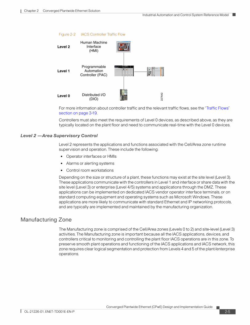
Thus, controllers (as shown in Figure 2-2) produce IACS network traffic in three directions from a level perspective:
• Downward to the devices in Level 0 that they control and manage
• Peer-to-peer to other controllers to manage the IACS for a Cell/Area zone
• Upward to HMIs and information management systems in Levels 2 and 3
2-4Converged Plantwide Ethernet (CPwE) Design and Implementation Guide
OL-21226-01, ENET-TD001E-EN-P
Chapter 2 Converged Plantwide Ethernet Solution
Industrial Automation and Control System Reference Model
Figure 2-2 IACS Controller Traffic Flow
For more information about controller traffic and the relevant traffic flows, see the “Traffic Flows” section on page 3-19.
Controllers must also meet the requirements of Level 0 devices, as described above, as they are typically located on the plant floor and need to communicate real-time with the Level 0 devices.
Level 2 —Area Supervisory Control
Level 2 represents the applications and functions associated with the Cell/Area zone runtime supervision and operation. These include the following:
• Operator interfaces or HMIs
• Alarms or alerting systems
• Control room workstations
Depending on the size or structure of a plant, these functions may exist at the site level (Level 3). These applications communicate with the controllers in Level 1 and interface or share data with the site level (Level 3) or enterprise (Level 4/5) systems and applications through the DMZ. These applications can be implemented on dedicated IACS vendor operator interface terminals, or on standard computing equipment and operating systems such as Microsoft Windows. These applications are more likely to communicate with standard Ethernet and IP networking protocols, and are typically are implemented and maintained by the manufacturing organization.
Manufacturing Zone
The Manufacturing zone is comprised of the Cell/Area zones (Levels 0 to 2) and site-level (Level 3) activities. The Manufacturing zone is important because all the IACS applications, devices, and controllers critical to monitoring and controlling the plant floor IACS operations are in this zone. To preserve smooth plant operations and functioning of the IACS applications and IACS network, this zone requires clear logical segmentation and protection from Levels 4 and 5 of the plant/enterprise operations.
Level 2
Level 1
Level 0
ProgrammableAutomation
Controller (PAC)
Distributed I/O(DIO)
Human MachineInterface
(HMI)
2276
42
2-5Converged Plantwide Ethernet (CPwE) Design and Implementation Guide
OL-21226-01, ENET-TD001E-EN-P
Chapter 2 Converged Plantwide Ethernet Solution
Industrial Automation and Control System Reference Model
Level 3—Site Level
Level 3, the site level, represents the highest level of the IACS. The systems and applications that exist at this level manage plantwide IACS functions. Levels 0 through 3 are considered critical to site operations. The applications and functions that exist at this level include the following:
• Level 3 IACS network
• Reporting (for example: cycle times, quality index, predictive maintenance)
• Plant historian
• Detailed production scheduling
• Site-level operations management
• Asset and material management
• Control room workstations
• Patch launch server
• File server
• Other domain services, e.g. Active Directory (AD), Dynamic Host Configuration Protocol (DHCP), Dynamic Naming Services (DNS), Windows Internet Naming Service (WINS), Network Time Protocol (NTP), etc.
• Terminal server for remote access support
• Staging area
• Administration and control applications
The Level 3 IACS network may communicate with Level 1 controllers and Level 0 devices, function as a staging area for changes into the Manufacturing zone, and share data with the enterprise (Levels 4 and 5) systems and applications through the DMZ. These applications are primarily based on standard computing equipment and operating systems (Unix-based or Microsoft Windows). For this reason, these systems are more likely to communicate with standard Ethernet and IP networking protocols.
Additionally, because these systems tend to be more aligned with standard IT technologies, they may also be implemented and supported by personnel with IT skill sets. These IT-skilled people may or may not belong organizationally to the IT department.
Enterprise Zone
Level 4—Site Business Planning and Logistics
Level 4 is where the functions and systems that need standard access to services provided by the enterprise network reside. This level is viewed as an extension of the enterprise network. The basic business administration tasks are performed here and rely on standard IT services. These functions and systems include wired and wireless access to enterprise network services such as the following:
• Access to the Internet Access to E-mail (hosted in data centers)
• Non-critical plant systems such as manufacturing execution systems and overall plant reporting, such as inventory, performance, etc.
• Access to enterprise applications such as SAP and Oracle (hosted in data centers)
2-6Converged Plantwide Ethernet (CPwE) Design and Implementation Guide
OL-21226-01, ENET-TD001E-EN-P
Chapter 2 Converged Plantwide Ethernet Solution
Industrial Automation and Control System Reference Model
Although important, these services are not viewed as critical to the IACS and thus the plant floor operations. Because of the more open nature of the systems and applications within the enterprise network, this level is often viewed as a source of threats and disruptions to the IACS network.
The users and systems in Level 4 often require summarized data and information from the lower levels of the IACS network. The network traffic and patterns here are typical of a branch or campus network found in general enterprises where approximately 90 percent of the network traffic goes to the Internet or to data center-based applications.
This level is typically under the management and control of the IT organization.
Level 5—Enterprise
Level 5 is where the centralized IT systems and functions exist. Enterprise resource management, business-to-business, and business-to-customer services typically reside at this level. Often the external partner or guest access systems exist here, although it is not uncommon to find them in lower levels (e.g., Level 3) of the framework to gain flexibility that may be difficult to achieve at the enterprise level. However, this approach may lead to significant security risks if not implemented within IT security policy and approach.
The IACS must communicate with the enterprise applications to exchange manufacturing and resource data. Direct access to the IACS is typically not required. One exception to this would be remote access for management of the IACS by employees or partners such as system integrators and machine builders. Access to data and the IACS network must be managed and controlled through the DMZ to maintain the security, availability, and stability of the IACS.
The services, systems, and applications at this level are directly managed and operated by the IT organization.
Converged Plantwide Ethernet Architectures
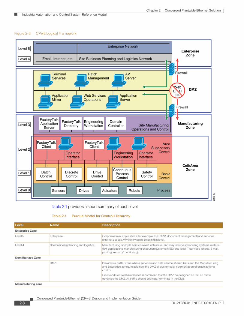
The Purdue Model and ISA-99 have identified levels of operations and key zones for the IACS logical framework. In addition to the levels and zones, Cisco and Rockwell Automation include a Demilitarized zone (DMZ) between the Enterprise and Manufacturing zones as part of CPwE architecture. Emerging IACS security standards such as ISA-99, NIST 800-82, and Department of Homeland Security INL/EXT-06-11478 also include a DMZ as part of a defense-in-depth strategy. The purpose of the DMZ is to provide a buffer zone where data and services can be shared between the Enterprise and Manufacturing zones. The DMZ is critical in maintaining availability, addressing security vulnerabilities, and abiding by regulatory compliance mandates (e.g., Sarbanes-Oxley). In addition, the DMZ allows for segmentation of organizational control; for example, between the IT organization and manufacturing. This segmentation allows different policies to be applied and contained. For example, the manufacturing organization may apply security and quality-of-service (QoS) policies that are different from the IT organization. The DMZ is where the policies and organizational control can be divided.
These levels and zones form the base logical framework around which the IACS network infrastructure and services are designed for the CPwE solution (see Figure 2-3).
The following sections contain a more detailed description of each zone, including the DMZ, and their related functions and components.
2-7Converged Plantwide Ethernet (CPwE) Design and Implementation Guide
OL-21226-01, ENET-TD001E-EN-P
Chapter 2 Converged Plantwide Ethernet Solution
Industrial Automation and Control System Reference Model
Figure 2-3 CPwE Logical Framework
Table 2-1 provides a short summary of each level.
TerminalServices
Level 5
Level 4
ApplicationMirror
Web ServicesOperations
OperatorInterface
OperatorInterface
EngineeringWorkstation
ApplicationServer
PatchManagement
Enterprise Network
Site Business Planning and Logistics NetworkEmail, Intranet, etc
AVServer
Level 3
Level 2
Level 1
Level 0
Cell/AreaZone
ManufacturingZone
DMZ
EnterpriseZone
Firewall
WebEmailCIP
Firewall
FactoryTalkClient
FactoryTalkClient
FactoryTalkApplication
Server
BatchControl
DiscreteControl
DriveControl
ContinuousProcessControl
SafetyControl
FactoryTalkDirectory
EngineeringWorkstation
DomainController Site Manufacturing
Operations and Control
AreaSupervisory
Control
BasicControl
ProcessSensors Drives RobotsActuators
2276
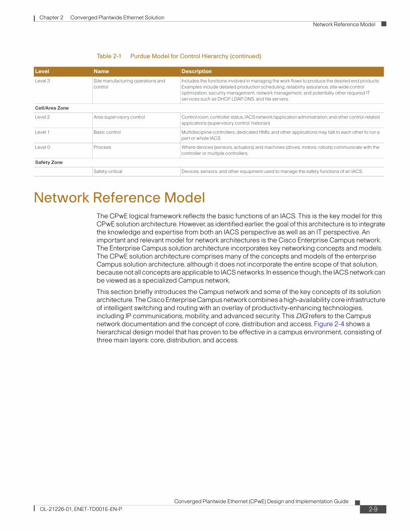
43Table 2-1 Purdue Model for Control Hierarchy
Level Name Description
Enterprise Zone
Level 5 Enterprise Corporate level applications (for example, ERP, CRM, document management) and services
(Internet access, VPN entry point) exist in this level.
Level 4 Site business planning and logistics Manufacturing facility IT services exist in this level and may include scheduling systems, material
flow applications, manufacturing execution systems (MES), and local IT services (phone, E-mail,
printing, security/monitoring).
Demilitarized Zone
DMZ Provides a buffer zone where services and data can be shared between the Manufacturing
and Enterprise zones. In addition, the DMZ allows for easy segmentation of organizational
control.
Cisco and Rockwell Automation recommend that the DMZ be designed so that no traffic
traverses the DMZ. All traffic should originate/terminate in the DMZ.
Manufacturing Zone
2-8Converged Plantwide Ethernet (CPwE) Design and Implementation Guide
OL-21226-01, ENET-TD001E-EN-P
Chapter 2 Converged Plantwide Ethernet Solution
Network Reference Model
Network Reference ModelThe CPwE logical framework reflects the basic functions of an IACS. This is the key model for this CPwE solution architecture. However, as identified earlier, the goal of this architecture is to integrate the knowledge and expertise from both an IACS perspective as well as an IT perspective. An important and relevant model for network architectures is the Cisco Enterprise Campus network. The Enterprise Campus solution architecture incorporates key networking concepts and models. The CPwE solution architecture comprises many of the concepts and models of the enterprise Campus solution architecture, although it does not incorporate the entire scope of that solution, because not all concepts are applicable to IACS networks. In essence though, the IACS network can be viewed as a specialized Campus network.
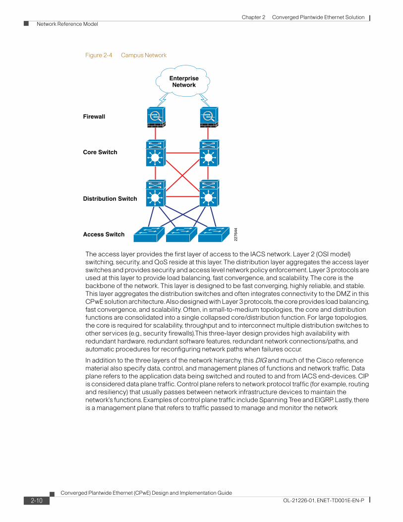
This section briefly introduces the Campus network and some of the key concepts of its solution architecture. The Cisco Enterprise Campus network combines a high-availability core infrastructure of intelligent switching and routing with an overlay of productivity-enhancing technologies, including IP communications, mobility, and advanced security. This DIG refers to the Campus network documentation and the concept of core, distribution and access. Figure 2-4 shows a hierarchical design model that has proven to be effective in a campus environment, consisting of three main layers: core, distribution, and access.
Level 3 Site manufacturing operations and
control
Includes the functions involved in managing the work flows to produce the desired end products.
Examples include detailed production scheduling, reliability assurance, site-wide control
optimization, security management, network management, and potentially other required IT
services such as DHCP, LDAP, DNS, and file servers.
Cell/Area Zone
Level 2 Area supervisory control Control room, controller status, IACS network/application administration, and other control-related
applications (supervisory control, historian)
Level 1 Basic control Multidiscipline controllers, dedicated HMIs, and other applications may talk to each other to run a
part or whole IACS.
Level 0 Process Where devices (sensors, actuators) and machines (drives, motors, robots) communicate with the
controller or multiple controllers.
Safety Zone
Safety-critical Devices, sensors, and other equipment used to manage the safety functions of an IACS.
Table 2-1 Purdue Model for Control Hierarchy (continued)
Level Name Description
2-9Converged Plantwide Ethernet (CPwE) Design and Implementation Guide
OL-21226-01, ENET-TD001E-EN-P
Chapter 2 Converged Plantwide Ethernet Solution
Network Reference Model
Figure 2-4 Campus Network
The access layer provides the first layer of access to the IACS network. Layer 2 (OSI model) switching, security, and QoS reside at this layer. The distribution layer aggregates the access layer switches and provides security and access level network policy enforcement. Layer 3 protocols are used at this layer to provide load balancing, fast convergence, and scalability. The core is the backbone of the network. This layer is designed to be fast converging, highly reliable, and stable. This layer aggregates the distribution switches and often integrates connectivity to the DMZ in this CPwE solution architecture. Also designed with Layer 3 protocols, the core provides load balancing, fast convergence, and scalability. Often, in small-to-medium topologies, the core and distribution functions are consolidated into a single collapsed core/distribution function. For large topologies, the core is required for scalability, throughput and to interconnect multiple distribution switches to other services (e.g., security firewalls).This three-layer design provides high availability with redundant hardware, redundant software features, redundant network connections/paths, and automatic procedures for reconfiguring network paths when failures occur.
In addition to the three layers of the network hierarchy, this DIG and much of the Cisco reference material also specify data, control, and management planes of functions and network traffic. Data plane refers to the application data being switched and routed to and from IACS end-devices. CIP is considered data plane traffic. Control plane refers to network protocol traffic (for example, routing and resiliency) that usually passes between network infrastructure devices to maintain the network's functions. Examples of control plane traffic include Spanning Tree and EIGRP. Lastly, there is a management plane that refers to traffic passed to manage and monitor the network
Core Switch
Firewall
Distribution Switch
Access Switch22
7644
EnterpriseNetwork
2-10Converged Plantwide Ethernet (CPwE) Design and Implementation Guide
OL-21226-01, ENET-TD001E-EN-P
Chapter 2 Converged Plantwide Ethernet Solution
Network Reference Model
infrastructure and services, an example of which would be SNMP or SSH traffic to monitor the switches and routers. These protocols may also be communicated to and from servers and other endpoints in the network.
In addition to the high availability switching and routing network, the Enterprise Campus architecture incorporates the following three core networking functions:
• Network security based on the Cisco Self-Defending network
• IP-based communications
• Mobility and wireless LAN services (not addressed in this version of the CPwE solution architecture)
For more information on the Enterprise Campus network, refer to the following URLs:
• Enterprise Campus Architecture: Overview and Framework
http://www.cisco.com/en/US/docs/solutions/Enterprise/Campus/campover.html
• Campus Network for High Availability Design Guide
http://www.cisco.com/en/US/docs/solutions/Enterprise/Campus/HA_campus_DG/hacampusdg.html#wp1107563
Access
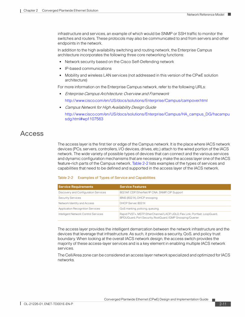
The access layer is the first tier or edge of the Campus network. It is the place where IACS network devices (PCs, servers, controllers, I/O devices, drives, etc.) attach to the wired portion of the IACS network. The wide variety of possible types of devices that can connect and the various services and dynamic configuration mechanisms that are necessary, make the access layer one of the IACS feature-rich parts of the Campus network. Table 2-2 lists examples of the types of services and capabilities that need to be defined and supported in the access layer of the IACS network.
The access layer provides the intelligent demarcation between the network infrastructure and the devices that leverage that infrastructure. As such, it provides a security, QoS, and policy trust boundary. When looking at the overall IACS network design, the access switch provides the majority of these access-layer services and is a key element in enabling multiple IACS network services.
The Cell/Area zone can be considered an access layer network specialized and optimized for IACS networks.
Table 2-2 Examples of Types of Service and Capabilities
Service Requirements Service Features
Discovery and Configuration Services 802.1AF, CDP, EtherNet/IP CNA, SNMP, CIP Support
Security Services IBNS (802.1X), DHCP snooping
Network Identity and Access DHCP Server, 802.1X
Application Recognition Services QoS marking, policing, queuing,
Intelligent Network Control Services Rapid PVST+, MSTP, EtherChannel/LACP, UDLD, Flex Link, Portfast, LoopGuard,
BPDUGuard, Port Security, RootGuard, IGMP Snooping/Querier
2-11Converged Plantwide Ethernet (CPwE) Design and Implementation Guide
OL-21226-01, ENET-TD001E-EN-P
Chapter 2 Converged Plantwide Ethernet Solution
Network Reference Model
Distribution
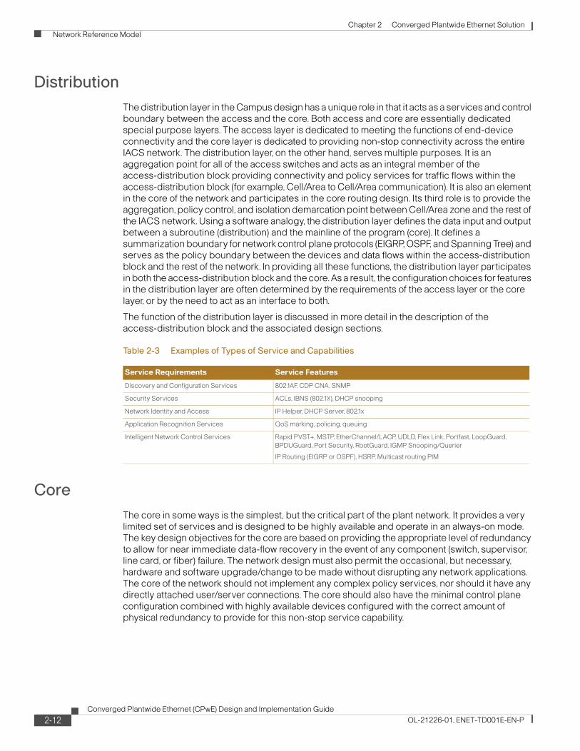
The distribution layer in the Campus design has a unique role in that it acts as a services and control boundary between the access and the core. Both access and core are essentially dedicated special purpose layers. The access layer is dedicated to meeting the functions of end-device connectivity and the core layer is dedicated to providing non-stop connectivity across the entire IACS network. The distribution layer, on the other hand, serves multiple purposes. It is an aggregation point for all of the access switches and acts as an integral member of the access-distribution block providing connectivity and policy services for traffic flows within the access-distribution block (for example, Cell/Area to Cell/Area communication). It is also an element in the core of the network and participates in the core routing design. Its third role is to provide the aggregation, policy control, and isolation demarcation point between Cell/Area zone and the rest of the IACS network. Using a software analogy, the distribution layer defines the data input and output between a subroutine (distribution) and the mainline of the program (core). It defines a summarization boundary for network control plane protocols (EIGRP, OSPF, and Spanning Tree) and serves as the policy boundary between the devices and data flows within the access-distribution block and the rest of the network. In providing all these functions, the distribution layer participates in both the access-distribution block and the core. As a result, the configuration choices for features in the distribution layer are often determined by the requirements of the access layer or the core layer, or by the need to act as an interface to both.
The function of the distribution layer is discussed in more detail in the description of the access-distribution block and the associated design sections.
Core
The core in some ways is the simplest, but the critical part of the plant network. It provides a very limited set of services and is designed to be highly available and operate in an always-on mode. The key design objectives for the core are based on providing the appropriate level of redundancy to allow for near immediate data-flow recovery in the event of any component (switch, supervisor, line card, or fiber) failure. The network design must also permit the occasional, but necessary, hardware and software upgrade/change to be made without disrupting any network applications. The core of the network should not implement any complex policy services, nor should it have any directly attached user/server connections. The core should also have the minimal control plane configuration combined with highly available devices configured with the correct amount of physical redundancy to provide for this non-stop service capability.
Table 2-3 Examples of Types of Service and Capabilities
Service Requirements Service Features
Discovery and Configuration Services 802.1AF, CDP CNA, SNMP
Security Services ACLs, IBNS (802.1X), DHCP snooping
Network Identity and Access IP Helper, DHCP Server, 802.1x
Application Recognition Services QoS marking, policing, queuing
Intelligent Network Control Services Rapid PVST+, MSTP, EtherChannel/LACP, UDLD, Flex Link, Portfast, LoopGuard,
BPDUGuard, Port Security, RootGuard, IGMP Snooping/Querier
IP Routing (EIGRP or OSPF), HSRP, Multicast routing PIM
2-12Converged Plantwide Ethernet (CPwE) Design and Implementation Guide
OL-21226-01, ENET-TD001E-EN-P
Chapter 2 Converged Plantwide Ethernet Solution
Network Reference Model
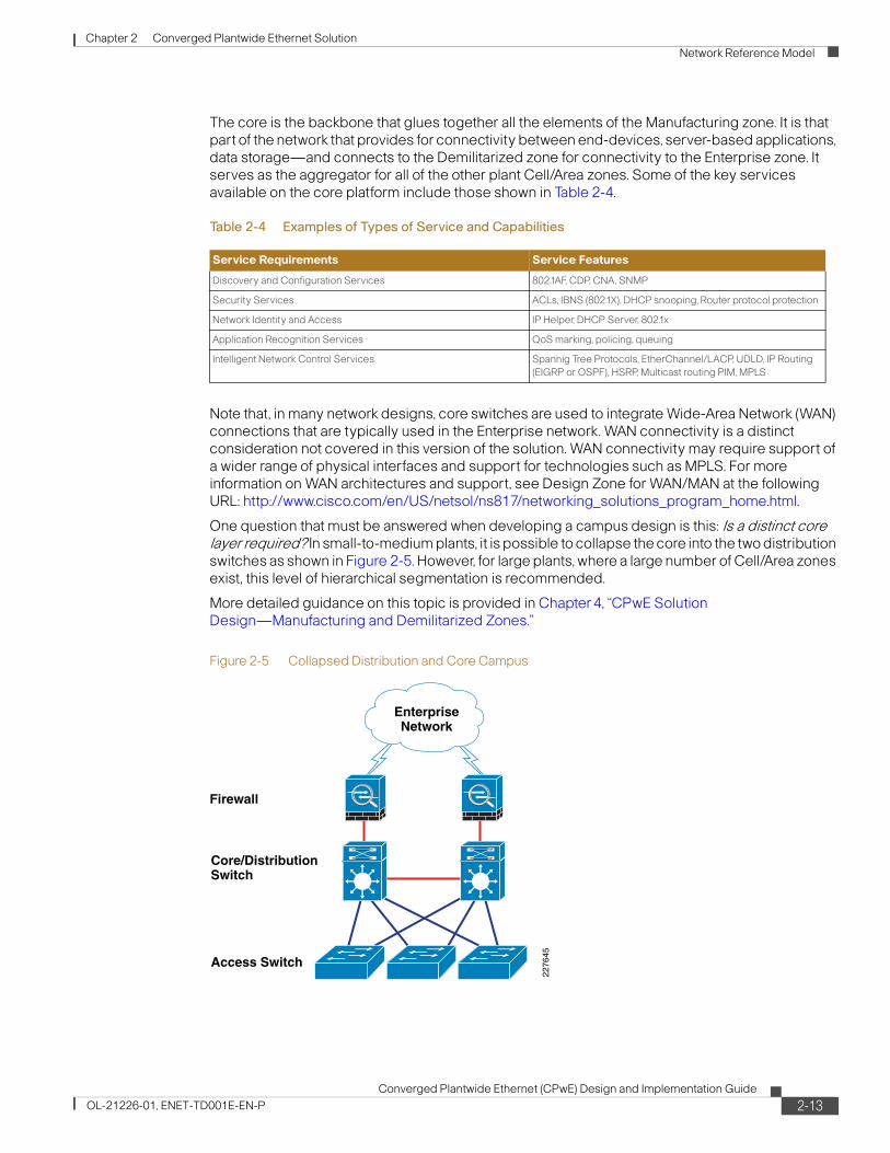
The core is the backbone that glues together all the elements of the Manufacturing zone. It is that part of the network that provides for connectivity between end-devices, server-based applications, data storage—and connects to the Demilitarized zone for connectivity to the Enterprise zone. It serves as the aggregator for all of the other plant Cell/Area zones. Some of the key services available on the core platform include those shown in Table 2-4.
Note that, in many network designs, core switches are used to integrate Wide-Area Network (WAN) connections that are typically used in the Enterprise network. WAN connectivity is a distinct consideration not covered in this version of the solution. WAN connectivity may require support of a wider range of physical interfaces and support for technologies such as MPLS. For more information on WAN architectures and support, see Design Zone for WAN/MAN at the following URL: http://www.cisco.com/en/US/netsol/ns817/networking_solutions_program_home.html.
One question that must be answered when developing a campus design is this: Is a distinct core layer required? In small-to-medium plants, it is possible to collapse the core into the two distribution switches as shown in Figure 2-5. However, for large plants, where a large number of Cell/Area zones exist, this level of hierarchical segmentation is recommended.
More detailed guidance on this topic is provided in Chapter 4, “CPwE Solution Design—Manufacturing and Demilitarized Zones.”
Figure 2-5 Collapsed Distribution and Core Campus
Table 2-4 Examples of Types of Service and Capabilities
Service Requirements Service Features
Discovery and Configuration Services 802.1AF, CDP, CNA, SNMP
Security Services ACLs, IBNS (802.1X), DHCP snooping, Router protocol protection
Network Identity and Access IP Helper, DHCP Server, 802.1x
Application Recognition Services QoS marking, policing, queuing
Intelligent Network Control Services Spannig Tree Protocols, EtherChannel/LACP, UDLD, IP Routing
(EIGRP or OSPF), HSRP, Multicast routing PIM, MPLS
Core/DistributionSwitch
Access Switch
2276
45
EnterpriseNetwork
Firewall
2-13Converged Plantwide Ethernet (CPwE) Design and Implementation Guide
OL-21226-01, ENET-TD001E-EN-P
Chapter 2 Converged Plantwide Ethernet Solution
CPwE—Converging Reference Models
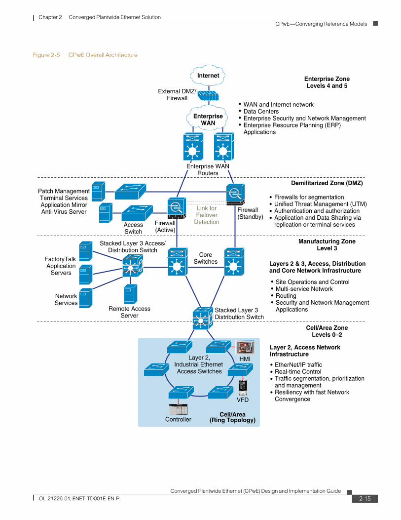
CPwE—Converging Reference ModelsThe overall objective of this CPwE solution is convergence of the IACS applications and networks with the enterprise systems and networks. To that end, this CPwE Design and Implementation Guide blends reference model terms and concepts from Campus, OSI, and the Six-Level Logical Plant architecture into both the CPwE Logical Framework shown in Figure 2-3 and the CPwE architecture shown in Figure 2-6. This section provides description on how some of these key terms are used.
The Cell/Area zone contains IACS devices from Levels 0 to 2. A device belongs to a single Cell/Area network. The Cell/Area IACS network is essentially a Layer-2 network, meaning that the MAC address of the IACS device is used to forward (switch) Implicit I/O and Explicit message traffic from the IACS device throughout the Cell/Area zone. A Layer-2 network also refers to a subnet, broadcast domain and a virtual LAN (VLAN). Cisco and Rockwell Automation recommend that there is a 1:1:1 relationship between subnets, broadcast domains. and VLANs. The Layer-2 network infrastructure devices in the Cell/Area zone are predominantly access switches. The ports on a distribution switch that aggregates the access switches are also typically part of the Layer-2 network and therefore considered part of the Cell/Area zone. The distribution switches in this document are depicted on the demarcation between the Manufacturing and Cell/Area zone as depicted in Figure 2-6. The distribution switch is also the Layer 2 to Layer 3 demarcation. There will be multiple Cell/Area zones within most plants.
The Manufacturing zone is analogous to a Campus network; many plants will have a single Manufacturing zone. The Manufacturing zone will have multiple Layer-2 networks, which may be Cell/Area zones or Level 3 IACS networks to connect Level 3 applications. The Manufacturing zone also has Layer-3 functions that forward IACS device traffic based upon the IP address. These Layer-3 functions are represented in the distribution and core functions described in the Campus reference model. The Manufacturing zone consists of IACS applications and network infrastructure including the following:
• All Cell/Area zones—IACS applications and Layer-2 networks
• Level 3, Plantwide IACS applications and devices
• Layer-2 networks and access switches to provide network connectivity to the Level 3 devices.
• Layer-3-capable distribution and core switches (or routers) that provide interconnectivity between Cell/Area zones, the DMZ, and any Manufacturing zone Layer-2 networks.
The Demilitarized zone (DMZ) is a zone between the Manufacturing and the Enterprise zones to securely manage the traffic flow between these networks. A plant firewall is implemented to manage the traffic flow and establish the DMZ.
2-14Converged Plantwide Ethernet (CPwE) Design and Implementation Guide
OL-21226-01, ENET-TD001E-EN-P
Chapter 2 Converged Plantwide Ethernet Solution
CPwE—Converging Reference Models
Figure 2-6 CPwE Overall Architecture
FactoryTalk Application
Servers
Enterprise ZoneLevels 4 and 5
Cell/Area ZoneLevels 0–2
CoreSwitches
Firewall(Standby)
Firewall(Active)
Patch ManagementTerminal ServicesApplication MirrorAnti-Virus Server Link for
FailoverDetection
HMILayer 2,Industrial Ethernet Access Switches
Cell/Area(Ring Topology)Controller
VFD
Manufacturing ZoneLevel 3
Internet
Demilitarized Zone (DMZ)
Stacked Layer 3Distribution Switch
EtherNet/IP traffic Real-time Control Traffic segmentation, prioritization and management Resiliency with fast Network Convergence
Stacked Layer 3 Access/Distribution Switch
NetworkServices
Remote AccessServer
Layers 2 & 3, Access, Distribution and Core Network Infrastructure
Layer 2, Access NetworkInfrastructure
Site Operations and ControlMulti-service NetworkRoutingSecurity and Network ManagementApplications
Firewalls for segmentationUnified Threat Management (UTM)Authentication and authorizationApplication and Data Sharing viareplication or terminal servicesAccess
Switch
WAN and Internet networkData CentersEnterprise Security and Network Management Enterprise Resource Planning (ERP)Applications
EnterpriseWAN
External DMZ/Firewall
Enterprise WANRouters
2-15Converged Plantwide Ethernet (CPwE) Design and Implementation Guide
OL-21226-01, ENET-TD001E-EN-P

Chapter 2 Converged Plantwide Ethernet Solution
CPwE—Converging Reference Models
2-16Converged Plantwide Ethernet (CPwE) Design and Implementation Guide
OL-21226-01, ENET-TD001E-EN-P