Embed Size (px)
Citation preview
Overprinting faulting mechanisms during the development of
multiple fault sets in sandstone, Chimney Rock fault array,
Utah, USA
Nicholas C. Davatzes*, Atilla Aydin, Peter Eichhubl
Department of Geological and Environmental Sciences, Stanford University, Stanford, CA 94305-2115, USA
Received 6 March 2002; accepted 1 November 2002
Abstract
The deformation mechanisms producing the Chimney Rock normal fault array (San Rafael Swell, Utah, USA) are identified
from detailed analyses of the structural components of the faults and their architecture. Faults in this area occur in four sets with
oppositely dipping fault pairs striking ENE and WNW. The ENE-striking faults initially developed by formation of deformation
bands and associated slip surfaces (deformation mechanism 1). After deformation band formation ceased, three sets of regional
joints developed. The oldest two sets of the regional joints, including the most prominent WNW-striking set, were sheared.
Localized deformation due to shearing of the WNW-striking regional joints formed WNW-striking map-scale normal faults. The
formation mechanism of these faults can be characterized by the shearing of joints that produces splay joints, breccia, and
eventually a core of fault rock (deformation mechanism 2). During this second phase of faulting, the ENE-striking faults were
reactivated by shear across the slip surfaces and shearing of ENE-striking joints, producing localized splay joints and breccia
(similar to deformation mechanism 2) superimposed onto a dense zone of deformation bands from the first phase. We found that
new structural components are added to a fault zone as a function of increasing offset for both deformation mechanisms.
Conversely, we estimated the magnitude of slip partitioned by the two mechanisms using the fault architecture and the
component structures. Our analyses demonstrate that faults in a single rock type and location, with similar length and offset, but
forming at different times and under different loading conditions, can have fundamentally different fault architecture. The
impact by each mechanism on petrophysical properties of the fault is different. Deformation mechanism 1 produces
deformations bands that can act as fluid baffles, whereas deformation mechanism 2 results in networks of joints and breccia that
can act as preferred fluid conduits. Consequently, a detailed analysis of fault architecture is essential for establishing an accurate
tectonic history, deformation path, and hydraulic properties of a faulted terrain.
D 2002 Elsevier Science B.V. All rights reserved.
Keywords: Deformation band; Joint; Sheared joint; Faulting mechanism; Fault architecture
1. Introduction
Two distinct mechanisms of fault formation in
sandstone have been described: (1) faults formed by
deformation bands and (2) faults formed by formation
0040-1951/02/$ - see front matter D 2002 Elsevier Science B.V. All rights reserved.
doi:10.1016/S0040-1951(02)00647-9
* Corresponding author.
E-mail addresses: [email protected]
(N.C. Davatzes), [email protected] (A. Aydin),
[email protected] (P. Eichhubl).
www.elsevier.com/locate/tecto
Tectonophysics 363 (2003) 1–18
and subsequent shearing of joints (Aydin, 2000). Each
mechanism produces a different set of structural
components with a characteristic geometry and dis-
tribution resulting in distinctive fault architectures.
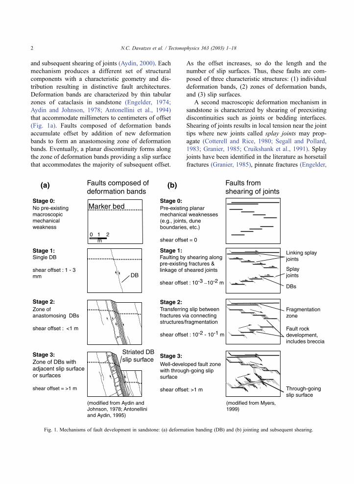
Deformation bands are characterized by thin tabular
zones of cataclasis in sandstone (Engelder, 1974;
Aydin and Johnson, 1978; Antonellini et al., 1994)
that accommodate millimeters to centimeters of offset
(Fig. 1a). Faults composed of deformation bands
accumulate offset by addition of new deformation
bands to form an anastomosing zone of deformation
bands. Eventually, a planar discontinuity forms along
the zone of deformation bands providing a slip surface
that accommodates the majority of subsequent offset.
As the offset increases, so do the length and the
number of slip surfaces. Thus, these faults are com-
posed of three characteristic structures: (1) individual
deformation bands, (2) zones of deformation bands,
and (3) slip surfaces.
A second macroscopic deformation mechanism in
sandstone is characterized by shearing of preexisting
discontinuities such as joints or bedding interfaces.
Shearing of joints results in local tension near the joint
tips where new joints called splay joints may prop-
agate (Cotterell and Rice, 1980; Segall and Pollard,
1983; Granier, 1985; Cruikshank et al., 1991). Splay
joints have been identified in the literature as horsetail
fractures (Granier, 1985), pinnate fractures (Engelder,
Fig. 1. Mechanisms of fault development in sandstone: (a) deformation banding (DB) and (b) jointing and subsequent shearing.
N.C. Davatzes et al. / Tectonophysics 363 (2003) 1–182
1987), splay fractures (Martel et al., 1988), splay
cracks (Martel, 1990), kink fractures (Cruikshank et
al., 1991), bridge cracks, and tail cracks (Cruikshank
and Aydin, 1994). We adopt the term splay joint to
emphasize that these structures are joints that form
under specific circumstances and result in a character-
istic geometry with respect to the sliding discontinu-
ity. Segall and Pollard (1983) and Martel (1988)
described joints that had been sheared and coalesced
into a through-going fault by a system of splay joints
in granodiorite. Myers (1999) documented the forma-
tion of zones of fragmentation, breccia, and fault rock
by the formation of splay joints that connected
sheared joints in en echelon or parallel arrays (Fig.
1b) in sandstone. As offset increases, early-formed
splay joints can be reactivated in shear and form a
second generation of splay joints (Myers, 1999). The
orientation of faults that incorporate multiple sheared
joints depends on how individual sheared joints are
linked by splay joints (e.g., the three cases in Fig. 1b).
Fault rock along this type of fault is characterized by
white color, grain size reduction, poor consolidation,
and is spatially associated with breccia and fragmen-
tation. The characteristic structures of ‘‘joint-based
faulting’’ include (1) joints (or other preexisting dis-
continuities, for example a slip surface), (2) sheared
joints, (3) splay joints, (4) zones of fragmentation, and
(5) fault rock (Myers, 1999).
The structural analysis of faulted terrains is com-
monly based on criteria including the length, height,
offset, spacing, and orientation of faults and sets of
faults (e.g., Anderson, 1951; Krantz, 1988; Barnett et
al., 1989; Dawers and Anders, 1995; Schlische et al.,
1996; Maerten, 2000). This type of analysis does not
adequately address the relative timing of faults or
properties of fault zones. We contend that a detailed
analysis of faulting mechanisms and the resulting
architecture complements a regional structural analy-
sis that intends to reconstruct the tectonic history of a
faulted terrain. Furthermore, we propose that recog-
nizing fault architecture as the product of specific
deformation mechanisms provides a basis for predict-
ing fault zone characteristics such as the occurrence
and distribution of joints, fragmented or brecciated
rock, or deformation bands along a fault.
Fault orientations, spacing, and slip have been used
to calculate the orientations and ratios of all three
principal strains (Krantz, 1988). Without distinguish-
ing phases of fault development, only the finite state
of strain is represented. Similarly, distinguishing neo-
formed faults from faults reactivated during a subse-
quent phase of fault activity is integral for accurate
stress inversion (Huang and Angelier, 1989) or for
fault slip distribution analysis (Maerten, 2000).
Whether a fault will act as fluid conduits or barriers
might depend on the development and distribution of
fault rock as well as the attendant structures like joints
and deformation bands in the damage zone (Chester
and Logan, 1986; Caine et al., 1996; Matthai et al.,
1998; Knipe et al., 1998; Taylor et al., 1999; Aydin,
2000; Flodin et al., 2001). Hence, the architecture,
temporal evolution, and overprinting relationships of
faults are crucial for elucidating hydrocarbon migra-
tion pathways and potential traps.
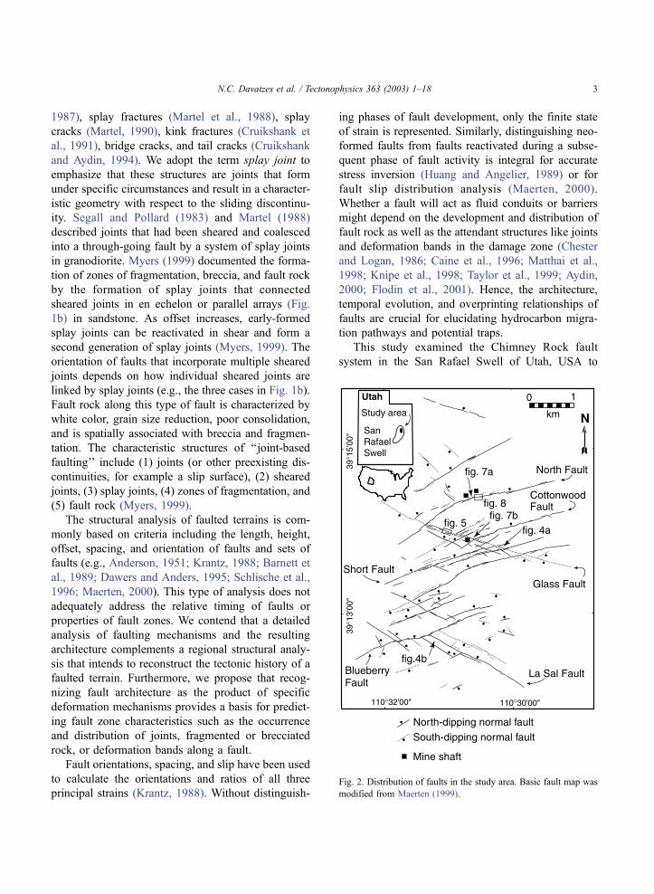
This study examined the Chimney Rock fault
system in the San Rafael Swell of Utah, USA to
Fig. 2. Distribution of faults in the study area. Basic fault map was
modified from Maerten (1999).
N.C. Davatzes et al. / Tectonophysics 363 (2003) 1–18 3
characterize deformation band and joint-based fault-
ing styles in multiple fault sets in a single location and
single rock type. We mapped the structural compo-
nents of faults to distinguish different mechanisms of
fault formation. Based on detailed mapping and anal-
yses, we estimated the relative contribution of the
structural products associated with each mechanism to
faulting. The macroscopic deformation mechanisms
provided a means to determine various phases of the
formation and evolution of a normal fault system
composed of multiple sets of faults in sandstone.
2. Geologic setting
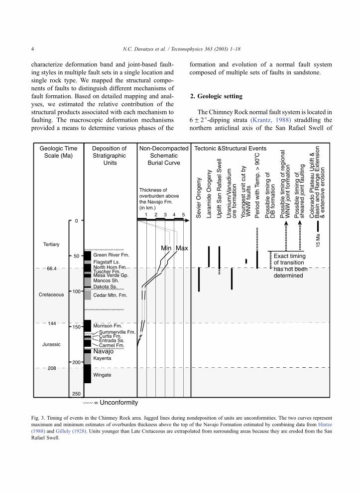
The Chimney Rock normal fault system is located in
6F 2j-dipping strata (Krantz, 1988) straddling the
northern anticlinal axis of the San Rafael Swell of
Fig. 3. Timing of events in the Chimney Rock area. Jagged lines during nondeposition of units are unconformities. The two curves represent
maximum and minimum estimates of overburden thickness above the top of the Navajo Formation estimated by combining data from Hintze
(1988) and Gilluly (1928). Units younger than Late Cretaceous are extrapolated from surrounding areas because they are eroded from the San
Rafael Swell.
N.C. Davatzes et al. / Tectonophysics 363 (2003) 1–184
central Utah, USA (Fig. 2). The swell is a dome-like
structure composed of a Phanerozoic sedimentary
sequence (Kelley, 1955; Dickinson and Snyder,
1978). The normal fault system offsets Jurassic Navajo
sandstone and overlying thinly bedded limestone, silt-
stone, and mudstone of the basal Carmel Formation. In
the study area, the eolian Navajo sandstone is a well-
sorted, cross-stratified, quartz arenite with 13–25%
porosity (Shipton and Cowie, 2001). Navajo Formation
thickness varies from 140–170 m (Gilluly, 1928;
Gilluly and Reeside, 1928). The footwalls of faults
up to 6 km long are exposed as scarps of resistant
Navajo sandstone. Polished and striated fault surfaces
along these scarps dip 55–90j (Krantz, 1989). Stria-
tions rake from 90–40jE and W (Maerten, 2000).
Maximum vertical offset across a single fault in the
entire study area is 38m (Maerten, 2000;Maerten et al.,
2001). Bedding plane exposure of Navajo sandstone
along faults is primarily limited to the footwall and fault
zones crossed by washes (Fig. 2).
Previous authors suggested that the timing of fault
formation coincided with uplift of the San Rafael
Swell during the Laramide orogeny between 66.4
and 37 Ma (Fig. 3) (Krantz, 1988; Maerten, 2000;
Shipton and Cowie, 2001). The timing of uplift of the
San Rafael Swell is constrained by changing alluvial
architecture and thinning of the Price River Formation
in the early Campanian (83.5–71.3 Ma) (Guiseppe
and Heller, 1998). During this period, the minimum
burial depth of the Navajo Formation was 2–4 km
(Fig. 3). The lack of intact units younger than Late
Cretaceous in the area does not allow reconstruction
of a definitive maximum burial depth. Previous
research at the Chimney Rock fault array in Utah
has focused on geometric, kinematic, and mechanical
characteristics of the fault array (Krantz, 1988; Cowie
and Shipton, 1998; Maerten, 2000; Shipton and
Cowie, 2001) but not on the occurrence and distribu-
tion of multiple faulting mechanisms.
3. Results
All exposed faults were examined for the occur-
rence, distribution, and relative timing of deformation
mechanisms. The North and Glass faults (Fig. 2) were
selected for detailedmapping to document and interpret
deformation mechanisms because of excellent expo-
sures. Locations isolated from fault intersections were
chosen to minimize the impact of different fault sets on
the occurrence, distribution, and orientations of struc-
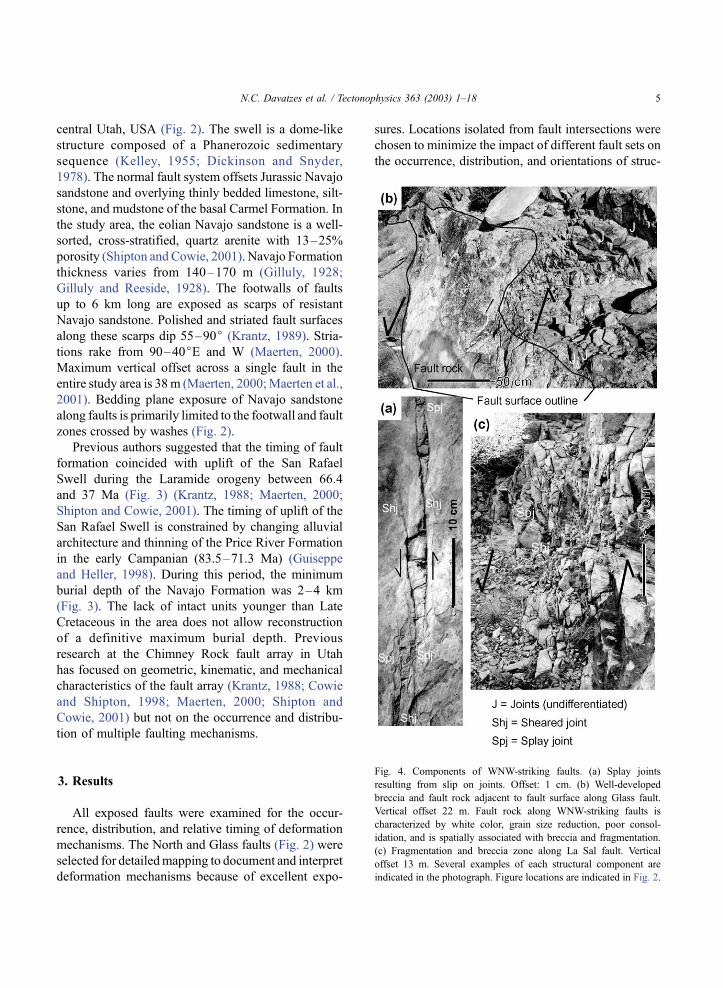
Fig. 4. Components of WNW-striking faults. (a) Splay joints
resulting from slip on joints. Offset: 1 cm. (b) Well-developed
breccia and fault rock adjacent to fault surface along Glass fault.
Vertical offset 22 m. Fault rock along WNW-striking faults is
characterized by white color, grain size reduction, poor consol-
idation, and is spatially associated with breccia and fragmentation.
(c) Fragmentation and breccia zone along La Sal fault. Vertical
offset 13 m. Several examples of each structural component are
indicated in the photograph. Figure locations are indicated in Fig. 2.
N.C. Davatzes et al. / Tectonophysics 363 (2003) 1–18 5

tures. The Glass fault (Fig. 2) is a WNW-striking and
SSW-dipping normal fault, with a maximum vertical
offset of about 38m. TheNorth fault (Fig. 2) is an ENE-
striking and NNW-dipping normal fault with a max-
imum vertical offset of about 28m. Detailed maps were
produced in the field on photographs obtained from a
camera suspended below a helium weather balloon
approximately 100 m above the outcrop (see Myers,
1999, for information about the technique). These
photographs provide sufficient resolution to record
the occurrence and types of structures that compose
the fault and damage zone. We mapped deformation
bands, zones of deformation bands and associated slip
surfaces, jointed deformation bands, joints, sheared
joints, fragmentation and breccia zones, and fault rock.
Structure frequency and orientation were measured
along scan lines normal to the faults. We present the
least complicated faults first, beginning with the Glass
and La Sal faults, and then move on to the more
complicated examples of the North and Cottonwood
faults (Fig. 2).
3.1. Structures composing WNW-striking faults
Along the Glass fault (Fig. 2), joints are the
dominant structural components. The trace of the
fault is characterized by a zone of high joint density
(Figs. 4 and 5). The upper and lower tips of joints
Fig. 5. Detailed map of portion of the Glass fault, offset in this location is approximately 36 m. The fault is principally composed of joints. Only
three deformation bands were mapped at the northern extremity of the map. Figure location is indicated in Fig. 2.
N.C. Davatzes et al. / Tectonophysics 363 (2003) 1–186
typically abut against cross-bedding or dune-bound-
ing surfaces. Some joints have preserved plumose
surface morphology (Pollard and Aydin, 1988). Other
discontinuities of the same orientation have normal
displacements of 0.5–5 cm, implying that joints
formed and were subsequently sheared. Younger
joints typically abut these sheared joints in a geom-
etry and sense of shear consistent with splay joints
(Figs. 1b and 4a).
Near the fault surface, some joints with splay joint
geometry accommodate shear offset. These sheared
splay joints also have abutting joints in splay joint
geometry. Fault surfaces that accommodate offset
greater than 1 m are consistently bordered by white
fault rock that is surrounded by breccia and frag-
mented rock (Fig. 4b). Breccia blocks are bounded by
sheared joints and joints. The density of joints is lower
at the margins of the breccia zone where some of these
joints are identifiable as splay joints from the age
relationship, sense of shear across the sheared joint,
and geometry. Several discontinuous and subparallel
fault surfaces bordered by breccia and zones of fault
rock are typically present along the Glass fault (e.g.,
Fig. 5). A single, continuous fault surface is exposed
for 10 m along the wall of a mineshaft (location in
Fig. 2). This fault surface is bordered by a continuous
zone of fault rock. The fault juxtaposes Navajo sand-
stone against Carmel Formation shale indicating offset
greater than 20 m.
The La Sal fault is one of the WNW-striking faults,
but in contrast to the Glass fault, it dips to the NNE
(Fig. 2). The fault zone is composed of joints (Fig. 4b
and c), sheared joints, and associated splay joints
similar to those described along the Glass fault. Other
faults in the WNW-striking pair of sets share this
architecture regardless of dip direction (Fig. 2). In all
cases, joint density is highest around the WNW-
striking faults consistent with the inferred deforma-
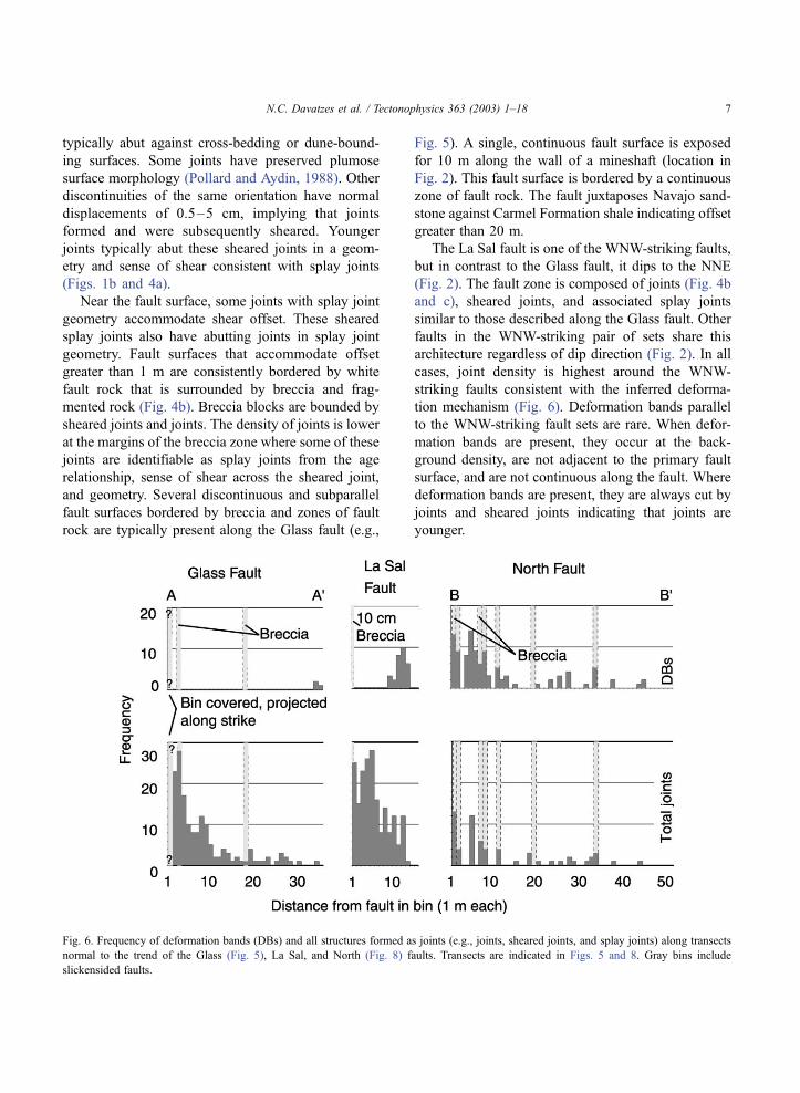
tion mechanism (Fig. 6). Deformation bands parallel
to the WNW-striking fault sets are rare. When defor-
mation bands are present, they occur at the back-
ground density, are not adjacent to the primary fault
surface, and are not continuous along the fault. Where
deformation bands are present, they are always cut by
joints and sheared joints indicating that joints are
younger.
Fig. 6. Frequency of deformation bands (DBs) and all structures formed as joints (e.g., joints, sheared joints, and splay joints) along transects
normal to the trend of the Glass (Fig. 5), La Sal, and North (Fig. 8) faults. Transects are indicated in Figs. 5 and 8. Gray bins include
slickensided faults.
N.C. Davatzes et al. / Tectonophysics 363 (2003) 1–18 7
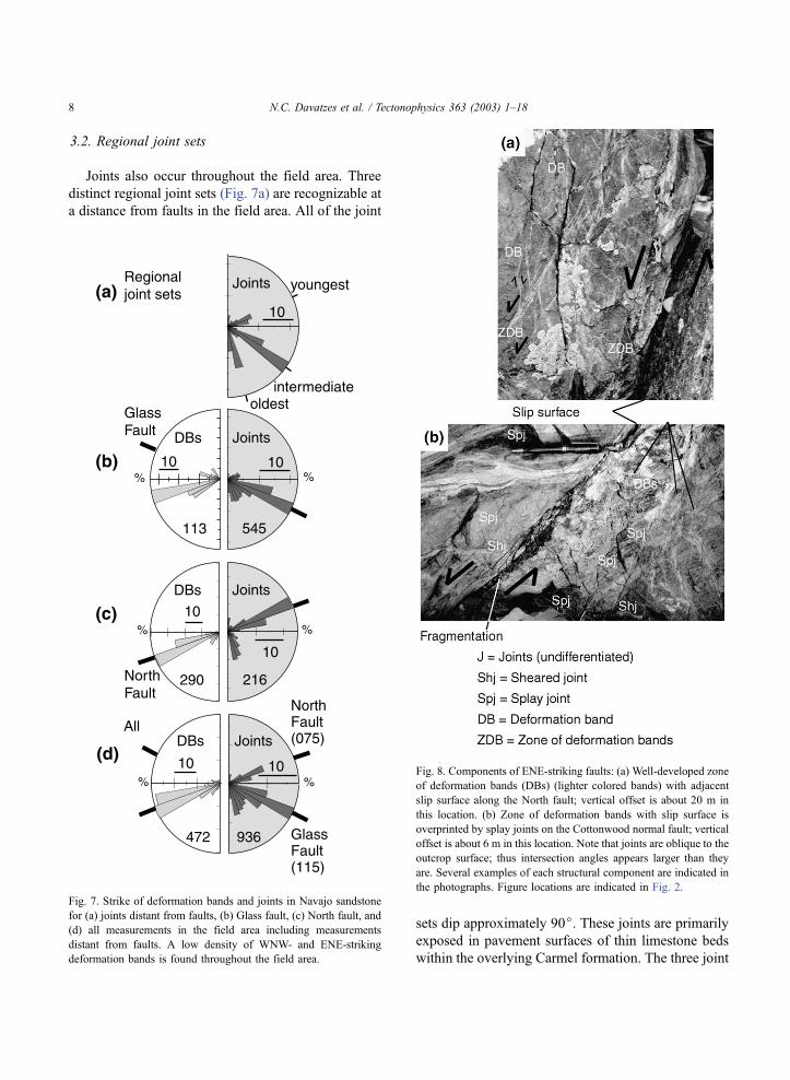
3.2. Regional joint sets
Joints also occur throughout the field area. Three
distinct regional joint sets (Fig. 7a) are recognizable at
a distance from faults in the field area. All of the joint
sets dip approximately 90j. These joints are primarily
exposed in pavement surfaces of thin limestone beds
within the overlying Carmel formation. The three joint
Fig. 7. Strike of deformation bands and joints in Navajo sandstone
for (a) joints distant from faults, (b) Glass fault, (c) North fault, and
(d) all measurements in the field area including measurements
distant from faults. A low density of WNW- and ENE-striking
deformation bands is found throughout the field area.
Fig. 8. Components of ENE-striking faults: (a) Well-developed zone
of deformation bands (DBs) (lighter colored bands) with adjacent
slip surface along the North fault; vertical offset is about 20 m in
this location. (b) Zone of deformation bands with slip surface is
overprinted by splay joints on the Cottonwood normal fault; vertical
offset is about 6 m in this location. Note that joints are oblique to the
outcrop surface; thus intersection angles appears larger than they
are. Several examples of each structural component are indicated in
the photographs. Figure locations are indicated in Fig. 2.
N.C. Davatzes et al. / Tectonophysics 363 (2003) 1–188
sets also appear to exist in limited exposures of the
Navajo sandstone distant from the faults. Consistent
relative ages between the joint sets are evident from
abutting relationships. The most prominent set of
joints strikes 110–140j (Fig. 7a) parallel to the
WNW-striking faults (Fig. 7b) and is intermediate in
age. The oldest and youngest joint sets oriented from
160j to 180j (Fig. 7a) and from 050j to 080j,respectively, are less prominent. Joints in the oldest
two sets were subjected to a small degree of shearing
evident from offset markers. The presence of WNW-
striking regional joints is consistent with development
of WNW-striking faults by shearing along the joints.
3.3. Structures composing ENE-striking faults
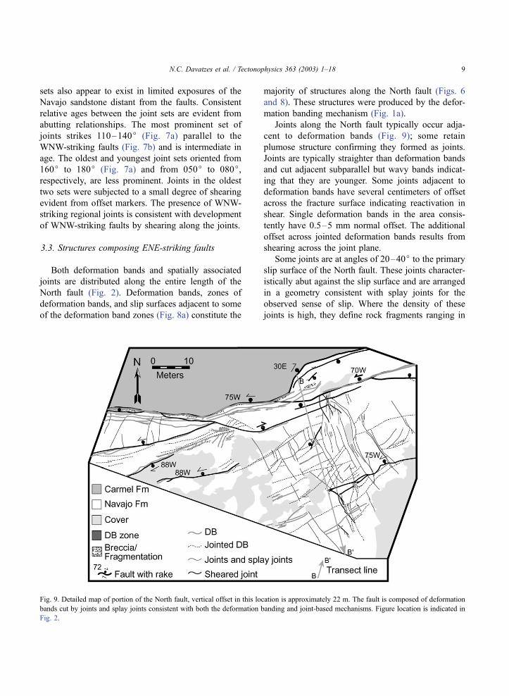
Both deformation bands and spatially associated
joints are distributed along the entire length of the
North fault (Fig. 2). Deformation bands, zones of
deformation bands, and slip surfaces adjacent to some
of the deformation band zones (Fig. 8a) constitute the
majority of structures along the North fault (Figs. 6
and 8). These structures were produced by the defor-
mation banding mechanism (Fig. 1a).
Joints along the North fault typically occur adja-
cent to deformation bands (Fig. 9); some retain
plumose structure confirming they formed as joints.
Joints are typically straighter than deformation bands
and cut adjacent subparallel but wavy bands indicat-
ing that they are younger. Some joints adjacent to
deformation bands have several centimeters of offset
across the fracture surface indicating reactivation in
shear. Single deformation bands in the area consis-
tently have 0.5–5 mm normal offset. The additional
offset across jointed deformation bands results from
shearing across the joint plane.
Some joints are at angles of 20–40j to the primary
slip surface of the North fault. These joints character-
istically abut against the slip surface and are arranged
in a geometry consistent with splay joints for the
observed sense of slip. Where the density of these
joints is high, they define rock fragments ranging in
Fig. 9. Detailed map of portion of the North fault, vertical offset in this location is approximately 22 m. The fault is composed of deformation
bands cut by joints and splay joints consistent with both the deformation banding and joint-based mechanisms. Figure location is indicated in
Fig. 2.
N.C. Davatzes et al. / Tectonophysics 363 (2003) 1–18 9
size from centimeters to about 1 m forming a weakly
defined breccia, similar to those along the Glass fault.
Some joints parallel to the fault may also have formed
as part of the youngest regional joint set, which has
similar strike (Fig. 7a).
The Cottonwood fault, another ENE-striking nor-
mal fault in the study area, (Fig. 2) provides one of the
best examples of overprinted faulting mechanisms
(Fig. 8b). The fault strikes 253j and dips 70–75j,with approximately 6 m of vertical offset at the
location of Fig. 8. The Cottonwood fault is composed
of a well-developed zone of deformation bands and
associated slip surface. The zone of deformation
bands is cut by joints that strike parallel to the fault
but dip between 50j and 90j in a direction opposite tothat of the fault (Fig. 8b). Joints of this orientation are
more abundant close to the fault (e.g., Fig. 6) and abut
against the fault slip surfaces. The geometry of these
joints and sense of offset that they indicate are
consistent with formation by splay jointing. At the
intersection of the joints with the deformation band
slip surface, increased fracture density fragmented the
rock forming a weakly defined breccia (Fig. 8b).
Similarly, joints subparallel to deformation bands
demonstrate slip (Fig. 8b to the right of the deforma-
tion band zone) and have associated splay joints.
Opening of splay joints that truncate against the
fault surface requires a small amount of offset across
the Cottonwood fault surface accompanying joint
formation. Because joints cut deformation bands, this
slip postdated deformation band formation. Similarly,
the occurrence of breccia overprinting deformation
bands indicates a magnitude of slip large enough to
lead to fragmentation and breccia formation by splay
jointing and shearing (Fig. 1b). A meter or more of
offset is estimated to be consistent with the breccia
formation. Thus, we partition the slip into two phases:
5 m of the total offset was accommodated during
deformation band formation and 1 m of offset asso-
ciated with additional slip across the original slip
surface that produced splay joints and breccia. There
may be a small contribution to the slip budget by
shearing of a few regional joints from the ENE-
striking set.
Deformation band density is greatest near the
primary fault slip surface and quickly drops to a
background density of less than one band/4 m about
45 m away from the fault (Fig. 6). In all cases
observed, joints cut deformation bands indicating that
joints and joint-related structures are younger.
3.4. Quantitative analysis of fault structural compo-
nents
The occurrence of structural components and fault
architecture described along the North, Cottonwood,
Glass, and La Sal faults were compared to all other
major faults exposed in the region (Fig. 2). ENE-
striking faults are consistently dominated by deforma-
tion bands and associated slip surfaces. In Contrast,
WNW-striking faults are consistently dominated by
joints, sheared joints, zones of fragmented rock,
breccia, and fault rock. In addition, there exist
regional joints sets and background deformation
bands that strike subparallel to faults throughout the
Chimney Rock area (Fig. 7). Deformation bands that
strike ENE are consistently cut by a small number of
deformation bands that strike WNW (Shipton and
Cowie, 2001). The deformation banding and joint-
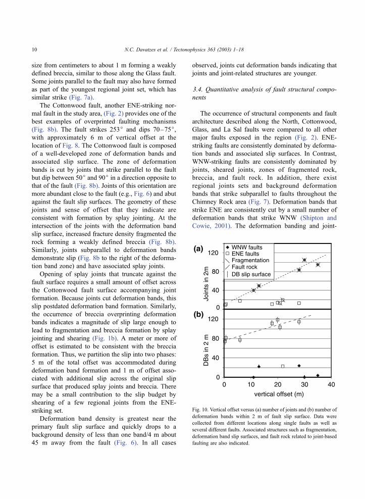
Fig. 10. Vertical offset versus (a) number of joints and (b) number of
deformation bands within 2 m of fault slip surface. Data were
collected from different locations along single faults as well as
several different faults. Associated structures such as fragmentation,
deformation band slip surfaces, and fault rock related to joint-based
faulting are also indicated.
N.C. Davatzes et al. / Tectonophysics 363 (2003) 1–1810

based faulting mechanisms each occur in faults dip-
ping north and south.
Fault development was investigated by measuring
the total number of joints and deformation bands
within 2 m of fault slip surfaces at locations with
different offsets. This method provided a means to
evaluate how individual structural components are
added as a function of fault slip. The window of
observation was chosen as a practical means of
gathering data from a wide range of faults and fault
offset despite limited exposure. The short distance
also allowed us to avoid fault intersections, where the
Fig. 11. Photomicrographs in plane-polarized, transmitted light of Navajo formation sandstone showing (a) quartz overgrowth on sand grains in
a deformation band as well as (b) quartz overgrowth in the host rock near a deformation band. The tight, angular geometry of overgrowths on
intact well-rounded sand grains typical of eolian deposits indicate they are diagenetic rather than inherited. Porosity was digitally enhanced for
clarity.
N.C. Davatzes et al. / Tectonophysics 363 (2003) 1–18 11
relationship between offset and fault structure is more
complicated. A 2-m interval is wide enough to char-
acterize changing deformation intensity within and
immediately adjacent to the fault zone based on
observations from longer scan lines. Finally, this
measurement is consistent with the hypothesis that
both zones of deformation bands and joints as splay
joints form adjacent to the fault due to continued slip
(Aydin and Johnson, 1978; Myers, 1999).
We sampled from multiple locations along the
North and Glass faults, as well as several faults with
small maximum offsets to assemble a representative
database of faults and their architecture. The density
of joints (including splay joints) on WNW-striking
faults increases with increasing offset (Fig. 10a). In
contrast, ENE-striking faults have a consistent density
of joints over offsets ranging from 45 cm to 28 m.
While deformation band density increases with
increasing offset on ENE-striking faults, WNW-strik-
ing faults have low or null deformation band density.
Fault rock and breccia are developed along WNW-
striking faults at all offsets plotted in Fig. 10; fault
rock characteristic of joint-based faulting is absent
along ENE-striking faults. Conversely, slip surfaces
associated with deformation band faults occur along
all ENE-striking faults in Fig. 10 beginning at offset
as small as 45 cm. The type of slip surface associated
with deformation band zones is not observed along
WNW-striking faults at any offset. There are, of
course, fault planes along WNW-striking faults but
these formed by shearing of joints and the related
products.
3.5. Fault formation and silica cementation
Sand grains in the Navajo Formation are cemented
by quartz overgrowths (Fig. 11). These overgrowths
are incorporated into deformation bands (right hand
side of Fig. 11) suggesting silica precipitation began
before or while the deformation bands formed. Areas
of intensely silica-cemented sandstone are localized
along some portions of the North and Cottonwood
faults implying these faults were partially established
prior to and influenced silica cementation. In contrast,
joints associated with these faults and at the intersec-
tion between the Cottonwood and Glass faults are
open and free of silica precipitation and therefore
postdate silica cementation of the sandstone.
4. Discussion
4.1. The faulting mechanisms
The structural components observed in the WNW-
striking Glass and La Sal faults, their arrangement
(Figs. 4–6), the relationship between offset and joint
density (Fig. 10), and the WNW-striking regional joint
set are consistent with formation by the joint-based
faulting mechanism (Fig. 1b). In contrast, the preva-
lence of deformation bands along the ENE-striking
North and Cottonwood faults (Figs. 6 and 8) and the
relationship between deformation band density and
offset (Fig. 10) indicate that these faults formed by
deformation banding (Fig. 1a). Joints are consistently
younger than deformation bands on these two faults.
In addition, the occurrence of sheared joints, splay
joints, and breccia characteristic of joint-based fault-
ing indicate that the North and Cottonwood faults
were later reactivated and the additional deformation
was accommodated by this mechanism (Fig. 1b). The
uniform density of joints along these faults is consis-
tent with a small, comparable contribution to slip by
the sheared joint-based faulting mechanism resulting
in splay joints (Fig. 10). These joints are superim-
posed on earlier deformation band faulting that
accommodates the majority of slip.
Offset across the ENE-striking North fault results
from the combined contributions of both deformation
mechanisms. The occurrence of breccia but lack of
appreciable fault rock suggests that the overall contri-
bution to slip by shearing across joints is probably no
more than 1–2 m (Fig. 1). Rock fragments are isolated
from the surrounding rock by joints, but are not yet
rotated or entrained and transported significantly along
the fault. The minimum offset associated with frag-
mentation is therefore related to the aperture and
density of joints in the fragmentation zone (Fig. 1b).
Brecciation requires larger rotation and transport of
rock, and thus it is associated with larger offset. Total
offset in the mapped location is 22 m; this suggests that
at least 20 m of offset was achieved through formation
of deformation bands and offset across the associated
slip surfaces. The structural components and their
arrangement along the North fault require (1) formation
of deformation bands, (2) formation of joints adjacent
to a preexisting deformation band, (3) formation of
joints as splay joints associated with slip on fault
N.C. Davatzes et al. / Tectonophysics 363 (2003) 1–1812
parallel joints and on slip surfaces that formed earlier
by the deformation banding mechanism.
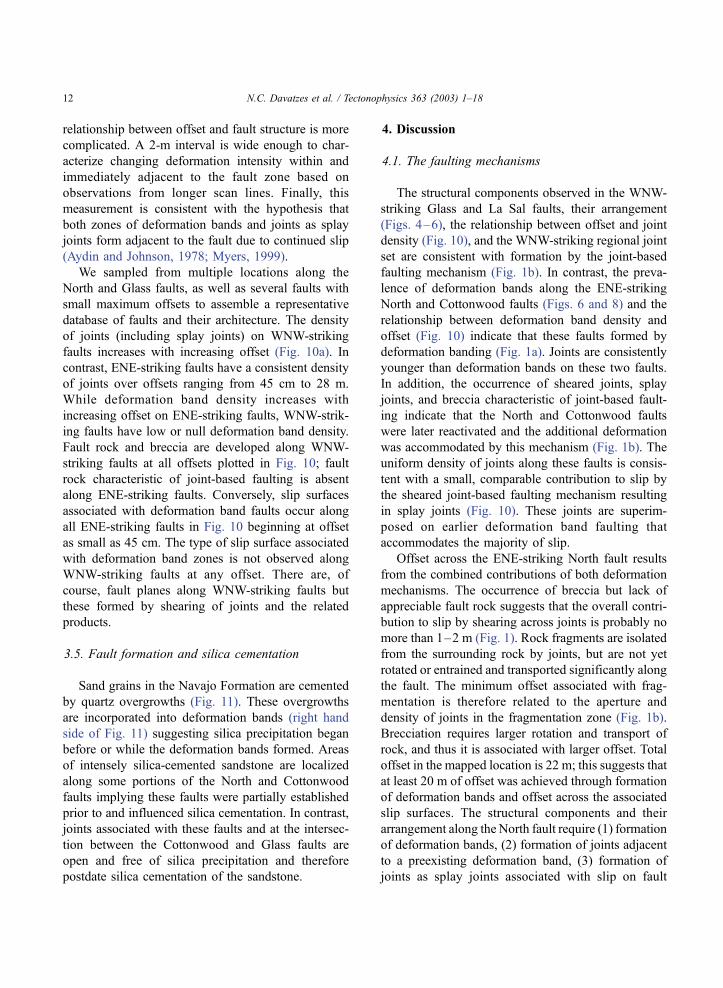
4.2. Development of the Chimney Rock fault array
The relative ages of structures produced by each
mechanism imply two phases of faulting characterized
by different deformation mechanisms. The first phase
of faulting was characterized by deformation bands.
Subsequently, the second phase of faulting was pre-
dominantly characterized by joints, sheared joints, and
related splay joints. Early deformation band formation
produced principally ENE-striking map-scale faults.
After the first phase of faulting, the formation of
regional joint sets marked a change in deformation
mechanism. Furthermore, the set of WNW-striking
joints provided discontinuities that localized shearing
leading to the formation of WNW-striking faults. The
overprinting of ENE-striking faults is manifested as
shearing of deformation band slip surfaces producing
splay joints and related products. Additional over-
printing might result from shearing of ENE-striking
joints formed along deformation bands or by shearing
of the regional ENE-striking joint set.
Each deformation mechanism during each respec-
tive phase of development caused the formation of
faults up to 6 km long with 30–40 m maximum
offset. The relative timing and orientation of structures
composing the faults suggest that the incremental
strain history of the fault array was non-coaxial. The
first phase accommodated dominantly NNW exten-
sion normal to the two early sets of ENE-striking
deformation band faults (Fig. 12). This was followed
by the second phase of faulting in which the extension
direction was dominantly NNE, normal to the set of
WNW-striking joints and subsequent sheared joint
based faults. Sometime during this second phase,
ENE-striking faults were reactivated. Several lines
of evidence, though not conclusive, are consistent
with the hypothesis that all sets of faults slipped
simultaneously for some portion near the end of the
second phase of deformation. First, joints, sheared
joints, and fragmentation similar to WNW-striking
faults overprint deformation bands on ENE-striking
faults along the slip surface. Second, the rake of
Fig. 12. Two phases of faulting: (1) Faulting characterized by
formation of deformation bands and slip surfaces in primarily two
conjugate sets, (2) faulting characterized by formation and
subsequent shearing of joints in two conjugate sets after rotation
of the primary extension direction. As all faults slip, a small amount
of extension also occurs to the ESE.
N.C. Davatzes et al. / Tectonophysics 363 (2003) 1–18 13
slickensides composing faults throughout Chimney
Rock rotates in proximity to fault intersections, indi-
cating mechanical interaction among sets of faults
(Maerten, 2000).
Previously, four fault sets with this geometry have
been interpreted to have formed simultaneously in
response to general three-dimensional strain (Oertel,
1965; Aydin and Reches, 1982; Krantz, 1988).
Krantz’s (1988) analysis derived the principal strain
ratios and orientations based on the fault geometry,
spacing, and offset distributions. His analysis assumed
coeval fault formation and uniform slip rate on all
fault sets resulting in coaxial strain. Multiple phases of
fault development were not distinguished. This study
indicates that formation of fault sets of different strike
was not coeval. In fact, ENE faults were reactivated
during the second phase of faulting that produced
WNW-striking faults. The two phases of faulting
distinguished by the fault architecture in this study
suggests non-coaxial strain. During the first phase, the
array accommodated predominantly plane strain (Fig.
12). In contrast, during the second phase, the array
accommodated three-dimensional strain since all the
faults sets were active (Fig. 12). This reconstruction
may only be consistent with the rake data that indicate
systematic change of slip direction with respect to the
fault intersections (Maerten, 2000) and that most
likely represent the last phase of slip on the faults.
Thus, the previous analyses quantify the finite strain
and the kinematic indicators of the last slip events but
do not account for sequential fault formation and non-
coaxiality in the strain path.
The relative contributions of each deformation
mechanism to accommodation of offset controls the
overall fault architecture including density, geometry,
and type of fault zone components such as joints or
deformation bands (Fig. 10). Even at low offset, faults
formed from joints define a wide zone of well-con-
nected fractures with initially discontinuous fault rock
pockets (disaggregated white gouge). Joint density
increases proportionally with increasing fault offset
as splay fractures form accompanying slip. These
joints and their shearing occurred preferentially along
older deformation bands thus contributing to the
further development of ENE faults. Along an estab-
lished fault surface, the offset required to form splay
joints might depend on the size of the sliding surface,
the stiffness, and frictional properties of the rock
(Cruikshank et al., 1991; Willemse and Pollard,
1998). Once slip occurs, many splay joints may form
in a wide area around the slipping fault. Deformation
band faults tend to develop tightly clustered zones of
deformation bands adjacent to the primary fault sur-
face at offsets as low as f 0.5 m. As offset increases,
a discrete slip surface forms and subsequently new
deformation bands.
Fossen and Hesthammer (1997) and Shipton and
Cowie (2001) observed a similar relationship between
fault offset and damage zone width in faults composed
of deformation bands and the associated slip surfaces
on the Colorado Plateau. They document large
increases in fault damage zone width with very small
increases in offset followed by smaller increases in
damage zone width per additional unit offset once the
fault reaches a few meters of offset. They associated
the decrease in damage zone expansion with offset
with the development of a through-going slip surface.
Cowie and Shipton (1998) offer an alternate interpre-
tation for a similar relationship based on examination
of the Blueberry fault (Fig. 2) and the Big Hole fault
south of Chimney Rock. They suggested that the
decrease in damage zone expansion resulted from a
transition from the interior of the fault to the fault tips
and related to fault propagation.
In general, results from this study indicate that the
addition of new structural elements to the fault is a
function of offset for both deformation band faults and
joint-based faults (Fig. 10). However, on a plot of
offset versus structure density, the slope is different
for each mechanism. This implies that a clear relation-
ship between fault zone characteristics like fault rock
thickness or damage zone width may not exist if more
than one mechanism contributes to fault development.
In addition, faults with the same offset or length will
have very different fault architecture if they form by
different deformation mechanisms.
4.3. Primary controls on deformation mechanisms
The deformation banding mechanism is controlled
by material properties at the grain scale including
porosity, sorting, and composition (Dunn et al., 1973;
Antonellini et al., 1994) and the state of stress (Wong
et al., 1997). In contrast, shearing of planar disconti-
nuities is controlled by the presence of macroscopic
flaws (e.g., joints, dune boundaries, pre-existing fault
N.C. Davatzes et al. / Tectonophysics 363 (2003) 1–1814
surfaces) in a favorable orientation to localize shear
stress (Brace and Bombolakis, 1963; Segall and
Pollard, 1983; Cooke, 1997). The formation of defor-
mation bands during early phases of faulting estab-
lishes an anisotropy that is exploited by subsequent
shearing along joints (Cruikshank et al., 1991; Anto-
nellini and Aydin, 1995). This may explain why joints
close to ENE-striking faults are parallel to the fault
rather than the WNW-striking set. Another possibility
is that the stress field perturbed by the nearby slipping
fault controlled the orientation of joints (Peacock,
2001; Bourne and Willemse, 2001).
Joints occupy a principal plane normal to the least
compressive stress during fracturing (Pollard and
Aydin, 1988). In order for joints to slip, shear stresses
must resolve on the joint plane and their magnitude
must exceed the frictional strength of the joint surfa-
ces. Shear stresses on the fracture plane can result
from either stress or material rotation. Dyer (1983)
and Cruikshank et al. (1991) recognized a complex
stress history characterized by rotation of the stress
field following joint formation leading to shearing of
the joints. In contrast, Peng and Johnson (1972)
advanced a conceptual model for failure of a granite
specimen in a triaxial deformation experiment on
granite. Failure begins with formation of closely
spaced en echelon joints. These joints define individ-
ual rock ‘‘beams’’ that subsequently rotate and fail by
slipping and forming connecting splay joints. This
model does not require rotation of the far-field stress.
Finally, the presence of some deformation bands and
the observation of joints along deformation bands
associated with WNW-striking faults suggest that
the deformation bands may have contributed to the
formation of some early joints slightly out of line with
respect to the regional stress field (Cruikshank et al.,
1991; Antonellini and Aydin, 1995).
It is unlikely that single joints span the more than
140 m thickness of the Navajo sandstone. Joints of
varying height controlled by cross-bedding, dune-
bounding surfaces, and other structures are most likely
distributed throughout the thickness. As a result, the
manner in which joints are sheared and linked by
splay joints ultimately controls the dip direction of the
resulting fault analogous to rock mechanics experi-
ments (Peng and Johnson, 1972). Similarly, the oppor-
tunity to form an extensive network of sheared joints
may be the primary control on the spacing of WNW
faults. This process also leads to the elevated joint
density near faults as splay joints are formed accom-
panying slip. The locally increased joint density,
fragmentation, breccia, and fault rock are radically
different than those of ENE faults characterized by
deformation bands.
Formation of quartz overgrowths on sand grains is
commonly observed at temperatures greater than 90 to
100 jC (Bjørlykke and Egeberg, 1993) in quartz rich
sandstones such as the Navajo Formation. If temper-
ature is controlled by burial, a normal geothermal
gradient of 30 jC/km requires 3 km of overburden to
achieve well-developed quartz overgrowth. Because
deformation band formation overlaps with silica
cementation this empirical relationship suggests that
deformation bands developed at or near the maximum
burial of the Navajo sandstone achieved during the
Laramide Orogeny (Fig. 3).
The transition between deformation mechanisms
may be initiated by a change in rheology or deforma-
tion environment or both. A change in rheology may
accompany cementation (Dvorkin and Nur, 1996). An
increase in cement and loss of pore space could render
the deformation banding mechanism unfavorable
(Aydin and Johnson, 1978; Antonellini et al., 1994).
Hence, continued silica precipitation may have been a
key cause of the change in faulting mechanism. In
addition, deformation bands generally form under
compressive differential stresses (Wong et al., 1997;
Mair et al., 2000) whereas joints require effective
tensile stress to form. A change in the deformation
environment, such as the state of stress or pore fluid
pressure, could cause a transition from deformation
banding to jointing. The inference that deformation
banding develops at conditions close to the maximum
burial depth might also suggest that the transition to
joint formation coincided with the onset of exhuma-
tion.
4.4. Implications for faults and fluid flow
Changing fault architecture between deformation
phases has a potential impact on the ability of a fault
to act as a fluid conduit or a barrier. The effects of a
fault on subsurface fluid flow results from the type of
structures composing the fault, their distribution, and
connectivity (Caine et al., 1996; Knipe et al., 1998;
Myers, 1999; Taylor et al., 1999; Aydin, 2000). How
N.C. Davatzes et al. / Tectonophysics 363 (2003) 1–18 15
and what elements are added during fault develop-
ment is a function of deformation mechanism and will
control the permeability behavior of the fault through
time. Joints and slightly sheared joints are potential
fluid conduits enhancing fluid flow parallel to the
joint (Taylor et al., 1999). Along faults formed by
shearing of joints and the attendant products (the
WNW-striking faults in this study), fault parallel
permeability is greatly increased whereas fault normal
fluid flow is reduced after a few meters of slip as
continuity of fault rock develops (Flodin et al., 2001;
Jourde et al., 2002). Deformation bands inhibit fault
normal fluid flow due to the porosity reduction in the
band (Antonellini et al., 1994; Matthai et al., 1998).
Furthermore, each mechanism is distinguished by the
number of structures accrued with offset. A dense
network of deformation bands will form with only
small slip, whereas joints easily cut and breach
deformation bands. The overprinting of these two
deformation products will result in a change of per-
meability behavior over time from primarily sealing to
largely conduit.
5. Conclusions
We have identified the structural components of
multiple fault sets in Chimney Rock, San Rafael
Swell, Utah, USA. The structural components are
organized into two distinct fault architectures charac-
teristic of faults formed by (1) deformation bands and
(2) by shearing of joints and associated splay jointing.
The distribution of structures produced by these
deformation mechanisms, their relative intensity, and
their temporal evolution allow us to partition the
deformation into two phases of faulting that could
not be distinguished based on the map-scale fault
pattern alone. The earlier phase involves deformation
band faults comprising two oppositely dipping sets
striking ENE–WSW and minor development of faults
striking WNW–ESE. The later phase of joint-based
faulting dominates fault development along WNW–
ESE faults and makes a minor contribution to ENE–
WSW faults. In summary, what appears to be nearly
homogeneous three-dimensional, fault-related strain
field was actually produced by two phases of faulting
reflected by a change in deformation mechanism. The
juxtaposition of both deformation mechanisms along
two well-defined pairs of fault sets with common
strike direction suggests that faults of different archi-
tecture can develop within a single rock type at the
same locality. We have demonstrated that faults with
the same geometric characteristics of length and offset
in a single rock type and locality can have radically
different fault architecture. The earlier faults com-
posed of deformation bands were probably sealing
for fluids. In contrast, later faulting probably estab-
lished higher permeability pathways because of joint
development and joints intersecting deformation
bands, thereby negating the sealing effect of the older
faults.
Acknowledgements
This work greatly benefited from support by
several individuals. Laurent Maerten shared maps,
data, and advice produced during his own work in the
Chimney Rock fault array. Bob Krantz, Mary Beth
Gray, and Phil Resor critically reviewed the manu-
script during its development and provided useful and
candid advice. Nick Davatzes would also like to
acknowledge the helpful environment and financial
support provided by the Rock Fracture Project that
contributed to the completion and quality of this work.
We thank Terry Engelder and Zoe Shipton for their
constructive reviews that helped to improve the
manuscript.
References
Anderson, E.M., 1951. The Dynamics of Faulting and Dyke For-
mation with Applications to Britain. Oliver & Boyd, Edinburgh.
206 pp.
Antonellini, M., Aydin, A., 1995. Effect of faulting on fluid flow in
porous sandstones; geometry and spatial distribution. Am. As-
soc. Pet. Geol. Bull. 79, 642–671.
Antonellini, M.A., Aydin, A., Pollard, D.D., 1994. Microstructure
of deformation bands in porous sandstones at Arches National
Park, Utah. J. Struct. Geol. 16, 941–959.
Aydin, A., 2000. Fractures, faults, and hydrocarbon entrapment,
migration and flow. Mar. Pet. Geol. 17, 797–814.
Aydin, A., Johnson, A.M., 1978. Development of faults as zones of
deformation bands and as slip surfaces in sandstone. Pure Appl.
Geophys. 116, 931–942.
Aydin, A., Reches, Z., 1982. Number and orientation of fault sets in
the field and in experiments. Geology 10, 107–112.
N.C. Davatzes et al. / Tectonophysics 363 (2003) 1–1816
Barnett, J.A.M., Mortimer, J., Rippon, J.H., Walsh, J.J., Watterson,
J., 1989. Displacement geometry in the volume containing a
single normal fault. Am. Assoc. Pet. Geol. Bull. 71, 925–937.
Bjørlykke, K., Egeberg, P.K., 1993. Quartz cementation in sedimen-
tary basins. Am. Assoc. Pet. Geol. Bull. 77, 1538–1548.
Bourne, S.J., Willemse, E.J.M., 2001. Elastic stress control on the
pattern of tensile fracturing around a small fault network at Nash
Point, UK. J. Struct. Geol. 23, 1753–1770.
Brace, W.F., Bombolakis, E.G., 1963. A note on brittle crack
growth in compression. J. Geophys. Res. 68, 3709–3713.
Caine, J.S., Evans, J.P., Forester, C.B., 1996. Fault zone architecture
and permeability structure. Geology 24, 1025–1028.
Chester, F.M., Logan, J.M., 1986. Implications for mechanical
properties of brittle faults from observations of the Punchbowl
Fault Zone, California. Pure Appl. Geophys. 124, 79–105.
Cooke, M.L., 1997. Fracture localization along faults with spatially
varying friction. J. Geophys. Res. 102, 22425–22434.
Cotterell, B., Rice, J.R., 1980. Slightly curved or kinked cracks. Int.
J. Fract. 16, 155–169.
Cowie, P.A., Shipton, Z.K., 1998. Fault tip displacement gradients
and process zone dimensions. J. Struct. Geol. 20, 983–997.
Cruikshank, K.M., Aydin, A., 1994. Role of fracture localization in
arch formation, Arches National Park, Utah. Geol. Soc. Am.
Bull. 106, 879–891.
Cruikshank, K.M., Zhao, G., Johnson, A.M., 1991. Analysis of
minor fractures associated with joints and faulted joints. J.
Struct. Geol. 13, 865–886.
Dawers, N.H., Anders, M.H., 1995. Displacement– length scaling
and fault linkage. J. Struct. Geol. 17, 607–614.
Dickinson, W.R., Snyder, W.S., 1978. Plate tectonics of the Lara-
mide Orogeny. Geol. Soc. Am. Mem. 151, 355–366.
Dunn, D.E., LaFountain, L.J., Jackson, R.E., 1973. Porosity de-
pendence and mechanism of brittle fracture in sandstones. J.
Geophys. Res. 78, 2403–2417.
Dvorkin, J., Nur, A., 1996. Elasticity of high-porosity sand-
stones: theory for two North Sea data sets. Geophysics 61,
1363–1370.
Dyer, J.R., 1983. Jointing in Sandstones, Arches National Park,
Utah. PhD thesis, Leland Jr. Stanford University, Stanford, CA.
Engelder, J.T., 1974. Cataclasis and the generation of fault gouge.
Geol. Soc. Am. Bull. 85, 1515–1522.
Engelder, J.T., 1987. Joints and shear fractures in rock. In: Atkin-
son, B.K. (Ed.), Fracture Mechanics of Rock. Academic Press,
London, pp. 27–69.
Flodin, E.A., Aydin, A., Durlofsky, L.J., Yeten, B., 2001. Repre-
sentation of fault zone permeability in reservoir flow models.
SPE paper 71671. SPE Annual Technical Conference and Ex-
hibition, New Orleans, p. 10.
Fossen, H., Hesthammer, J., 1997. Geometric analysis and scaling
relations of deformation bands in porous sandstone. J. Struct.
Geol. 19, 1479–1493.
Gilluly, J., 1928. United States geology and oil and gas prospects of
parts of the San Rafael Swell, Utah. U.S. Geol. Surv. Bull. 806-
C, 69–130.
Gilluly, J., Reeside Jr., J.B., 1928. Sedimentary rocks of the San
Rafael Swell and some adjacent areas in eastern Utah. U.S.
Geol. Prof. Pap. P0150-D, 61–110.
Granier, T., 1985. Origin, damping, and pattern of development of
faults in granite. Tectonics 4, 721–737.
Guiseppe, A.C., Heller, P.L., 1998. Long-term river response to
regional doming in the Price River Formation, central Utah.
Geology 26, 239–242.
Hintze, L.F., 1988. Geologic history of Utah. Brigham Young Uni-
versity Geology Studies Special Publication 7. Brigham Young
University, Provo, UT, p. 202.
Huang, Q., Angelier, J., 1989. Inversion of field data in fault tec-
tonics to obtain the regional stress: II. Using conjugate fault sets
within heterogeneous families for computing palaeostress axes.
Geophys. J. 96, 139–149.
Jourde, H., Flodin, E.A., Aydin, A., Durlofsky, L.J., Wen, X.-H.,
2002. Computing permeability of fault zones in aeolian sand-
stone from outcrop measurements. Am. Assoc. Pet. Geol. Bull.
86, 1187–1200.
Kelley, V.C., 1955. Monoclines of the Colorado Plateau. Geol. Soc.
Am. Bull. 66, 789–803.
Knipe, R.J., Jones, G., Fisher, Q.J., 1998. Faulting, fault sealing and
fluid flow in hydrocarbon reservoirs: an introduction. In: Knipe,
R.J., Jones, G., Fisher, Q.J. (Eds.), Faulting, Fault Sealing and
Fluid Flow in Hydrocarbon Reservoirs. Geological Society,
London, Special Publications, vol. 147, pp. vii –xxi.
Krantz, R.W., 1988. Multiple fault sets and three-dimensional
strain; theory and application. J. Struct. Geol. 10, 225–237.
Krantz, R.W., 1989. Orthorhombic fault patterns; the odd axis
model and slip vector orientations. Tectonics 8, 483–495.
Maerten, L., 1999. Mechanical Interaction of Intersecting Nor-
mal Faults; Theory, Field Examples and Application. Ph.D.
thesis, Leland Stanford Jr. University, Stanford, California.
167 pp.
Maerten, L., 2000. Variation in slip on intersecting normal faults:
implications for paleostress inversion. J. Geophys. Res. 105,
25553–25565.
Maerten, L., Pollard, D.D., Maerten, F., 2001. Digital mapping of
three-dimensional structures of the Chimney Rock fault system,
central Utah. J. Struct. Geol. 23, 585–592.
Mair, K., Main, I., Elphick, S., 2000. Sequential growth of defor-
mation bands in the laboratory. J. Struct. Geol. 22, 25–42.
Martel, S.J., 1988. Formation of compound strike – slip fault
zones, Mount Abbot Quadrangle, California. J. Struct. Geol.
12, 869–882.
Martel, S.J., 1990. Formation of compound strike-slip fault zones,
Mount Abbot Quadrangle. J. Struct. Geol. 12, 869–882.
Martel, S.J., Pollard, D.D., Segall, P., 1988. Formation of com-
pound strike–slip fault zones, Mount Abbot Quadrangle, Cal-
ifornia. J. Struct. Geol. 12, 869–882.
Matthai, S.K., Aydin, A., Pollard, D.D., Roberts, S.G., Fisher, Q.J.,
Knipe, R.J., 1998. Numerical simulation of departures from
radial drawdown in a faulted sandstone reservoir with joints
and deformation bands. In: Jones, G., Fisher, Q.J., Knipe, R.J.
(Eds.), Faulting, Fault Sealing and Fluid Flow in Hydrocarbon
Reservoirs. Geological Society, London, Special Publications,
vol. 147, pp. 157–191.
Myers, R.D., 1999. Structure and Hydraulics of Brittle Faults in
Sandstone. PhD thesis, Leland Stanford Jr. University, Stanford,
California. 176 pp.
N.C. Davatzes et al. / Tectonophysics 363 (2003) 1–18 17
Oertel, G., 1965. The mechanics of faulting in clay experiments.
Tectonophysics 2, 343–393.
Peacock, D.C.P., 2001. The temporal relationships between joints
and faults. J. Struct. Geol. 23, 329–341.
Peng, S., Johnson, A.M., 1972. Crack growth and faulting in cylin-
drical specimens of Chelmsford granite. Int. J. Rock Mech. Min.
Sci. 9, 37–86.
Pollard, D.D., Aydin, A., 1988. Progress in understanding jointing
over the past century. Geol. Soc. Am. Bull. 100, 1181–1204.
Schlische, R.W., Young, S.S., Ackermann, R.V., Gupta, A., 1996.
Geometry and scaling relations of a population of very small
rift-related normal faults. Geology 24, 683–686.
Segall, P., Pollard, D.D., 1983. Nucleation and growth of strike slip
faults in granite. J. Geophys. Res. 88, 555–568.
Shipton, Z.K., Cowie, P.A., 2001. Analysis of three-dimensional
fault zone structures over a micrometer to km scale range in
the high-porosity Navajo sandstone, Utah. J. Struct. Geol. 23,
1825–1844.
Taylor, L., Pollard, A., Aydin, A., 1999. Fluid flow in discrete joint
sets; field observations and numerical simulations. J. Geophys.
Res. 104, 28983–29006.
Willemse, E.J.M., Pollard, D.D., 1998. On the orientation and pat-
terns of wing cracks and solution surfaces at the tips of a sliding
flaw or fault. J. Geophys. Res. 103, 2427–2438.
Wong, T.-F., David, C., Zhu, W., 1997. The transition from brittle
faulting to cataclastic flow in porous sandstones; mechanical
deformation. J. Geophys. Res. 102, 3009–3025.
N.C. Davatzes et al. / Tectonophysics 363 (2003) 1–1818