Embed Size (px)
Citation preview
EWIKON Heißkanalsysteme GmbH Siegener Straße 35 • 35066 Frankenberg • Tel: +49 6451 501-0 Fax: +49 6451 501-202 • E-Mail: [email protected] • www.ewikon.com
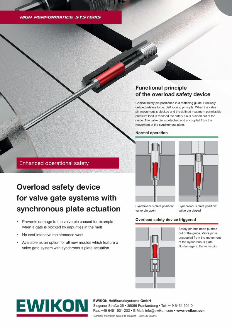
Functional principle of the overload safety device
Overload safety device for valve gate systems with synchronous plate actuation• Prevents damage to the valve pin caused for example
when a gate is blocked by impurities in the melt
• No cost-intensive maintenance work
• Available as an option for all new moulds which feature a valve gate system with synchronous plate actuation
Safety pin has been pushed out of the guide. Valve pin is uncoupled from the movement of the synchronous plate. No damage to the valve pin
Synchronous plate position: valve pin open
Synchronous plate position: valve pin closed
Normal operation
Overload safety device triggered
Conical safety pin positioned in a matching guide. Precisely defined release force. Self locking principle. When the valve pin movement is blocked and the defined maximum permissible pressure load is reached the safety pin is pushed out of the guide. The valve pin is detached and uncoupled from the movement of the synchronous plate.
Technical information subject to alteration EWIKON 06/2019
Enhanced operational safety