Embed Size (px)
Citation preview
1
Low Voltage Products & Systems 2.AABB Inc. • 888-385-1221 • www.abb-control.com AC 1000 - 11/03
2
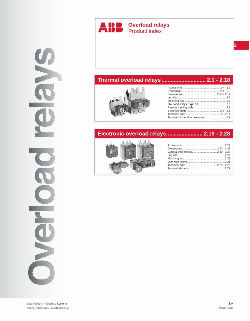
Thermal overload relays ............................. 2.1 - 2.18
Electronic overload relays........................ 2.19 - 2.28
Overload relaysProduct index
Accessories .................................................2.7 - 2.8Description ..................................................2.1 - 2.3Dimensions..............................................2.15 - 2.17Lug kits ................................................................2.7Mounting kits .......................................................2.7Overload relays, Type TA ....................................2.6Remote tripping coils ...........................................2.8Selection guide............................................2.4 - 2.5Technical data ...........................................2.9 - 2.14Terminal blocks & accessories ............................2.7
Accessories .......................................................2.22Dimensions..............................................2.27 - 2.28General information.................................2.19 - 2.20Lug kits ..............................................................2.22Mounting kits .....................................................2.22Overload relays .................................................2.21Technical data .........................................2.23 - 2.26Terminal shrouds ...............................................2.22

1
2.B Low Voltage Products & Systems
AC 1000 - 11/03 ABB Inc. • 888-385-1221 • www.abb-control.com
2
2
2Thermal
Overloadrelays
Low Voltage Products & Systems 2.1ABB Inc. • 888-385-1221 • www.abb-control.com AC 1000 - 11/03
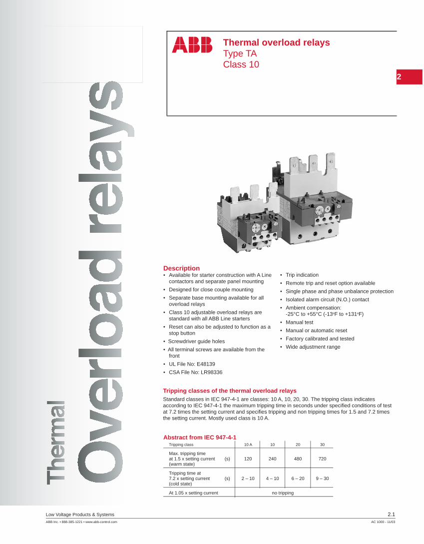
Thermal overload relaysType TAClass 10
Description• Available for starter construction with A Line
contactors and separate panel mounting
• Designed for close couple mounting
• Separate base mounting available for all overload relays
• Class 10 adjustable overload relays are standard with all ABB Line starters
• Reset can also be adjusted to function as a stop button
• Screwdriver guide holes
• All terminal screws are available from the front
• UL File No: E48139
• CSA File No: LR98336
• Trip indication
• Remote trip and reset option available
• Single phase and phase unbalance protection
• Isolated alarm circuit (N.O.) contact
• Ambient compensation: -25°C to +55°C (-13oF to +131oF)
• Manual test
• Manual or automatic reset
• Factory calibrated and tested
• Wide adjustment range
Tripping classes of the thermal overload relaysStandard classes in IEC 947-4-1 are classes: 10 A, 10, 20, 30. The tripping class indicates according to IEC 947-4-1 the maximum tripping time in seconds under specifi ed conditions of test at 7.2 times the setting current and specifi es tripping and non tripping times for 1.5 and 7.2 times the setting current. Mostly used class is 10 A.
Abstract from IEC 947-4-1Tripping class 10 A 10 20 30
Max. tripping timeat 1.5 x setting current (s) 120 240 480 720(warm state)
Tripping time at7.2 x setting current (s) 2 – 10 4 – 10 6 – 20 9 – 30(cold state)
At 1.05 x setting current no tripping

2
2Thermal
Overload
relays
2.2 Low Voltage Products & Systems
AC 1000 - 11/03 ABB Inc. • 888-385-1221 • www.abb-control.com
Frame sizeTA....DU
Amp setting range
Signaling contact, (97, 98) Terminals T1, T2, T3
Manual test
Manual or automatic reset
Trip indication light
Tripping contact (95, 96)
Terminals L1, L3, L5
Description
TA thermal overload relays are used with A Line contactors for the protection of motors having a nominal voltage of up to 600VAC max per UL/CSA (690VAC and 800VDC per IEC).
Product range• Standard relays:
Types: TA25DU, TA42DU, TA75DU, TA80DU, TA110DU, TA200DU and TA450DU
– TA25 to TA110 and TA200 are directly connected in the motor circuit. – TA450DU relays are fed through a linear type transformer
• Special constructionThermal overload relays with different certifi cations and approvals.Relays for protection EEx e motors.
Construction and function• General
Thermal O/L relays and their accessories meet UL, CSA and most other important international standards (IEC), European standards (EN) and the most important national standards (DIN-VDE, NFC-UTE, BS, etc.). They meet the certifi cation and approval directives required throughout the world.
Thermal overload relays are 3 pole. The motor current fl ows through their bimetals (1 per phase) which are indirectly heated. Under the effect of the heating, the bimetals bend, cause the relay to trip and the position of the auxiliary contacts to change.
The relay setting range is graduated in amps. In compliance with international and national standards, the setting current is the motor nominal current and not the tripping current (no tripping at 1.05 x setting current, tripping at 1.2 times setting current).
The tripping curves (cold or warm starting, 3 phases and 2 phases) are shown on page 2.14.
The relays are built to be self protecting in the event of an overload until the short circuit protection device is activated.
2
2Thermal
Overloadrelays
Low Voltage Products & Systems 2.3ABB Inc. • 888-385-1221 • www.abb-control.com AC 1000 - 11/03
TA25DU
Description
ApplicationTechnical data• All the relays have:
– Free tripping: the resetting button, even if held in, does not prevent tripping of the thermal overload relay in the event of a fault. – Temperature compensation – Phase failure protection according to IEC 947-4-1: Within the limits of the setting range, a reduced tripping time, and thus improved motor protection, is obrtained in case of a phase failure. – Tripping class: 10A, for TA relays – Test functions and resetting: see table below.
• Auxiliary contactsThe relays have two built in auxiliary contacts: NC marked 95-96; NO marked 97-98. Both contacts are physically separate and can thus be used for 2 different circuits (control circuit and indication circuit).
Function of TA25DU – TA450DU thermal O/L relays Resetting Relay tripped 95-96 Open Relay not tripped 95-96 Closed 97-98 Closed 97-98 Open
Contacts Manual Automatic Both manual and automatic
Effect of blue Resetting Yes No No
button indexed 95-96 Closed when the on R button is pressed
No effect No effect(RESET ONLY) 97-98 Open when the button is pressed
Effect of blue Resetting Yes No No
button indexed 95-96 Closed when the Open when the button is pressedon R/O button is released Closed when the button is released
(RESET/OFF) 97-98
Open when the No effect button is pressed
No effect

2
2Thermal
Overload
relays
2.4 Low Voltage Products & Systems
AC 1000 - 11/03 ABB Inc. • 888-385-1221 • www.abb-control.com
Selection guideTA25DU – TA80DU
Types TA25DU TA42DU TA75DU TA80DU
Main characteristics
Construction 3 pole with ambient temperature variation compensation. Protection against single phase op er a tion. Built in auxiliary con tacts: 1N.O. + 1N.C.
Resetting Convertible: Manual to Automatic
Setting ranges Number 18 3 6 4
from 0.1 – 0.16A 18 – 25A 18 – 25A 29 – 42A to 24 – 32A 29 – 42A 60 – 80A 60 – 80A
Mounted with contactorsMounting kit No kit is required for mounting ther mal O/L relays below contactors
Types of contactors A/AE/AL9 for combined mounting A/AE/AL12 A/AE/AL16 A/AE/AL26 A/AE/AL30 A/AE30
A/AE/AL40 A/AE40
A/AE/AF50 A/AE/AF63 A/AE/AF75
A/AE/AF95 A/AE/AF110
Mounted separately (i.e. separate from contactor)Separate mounting kit DB25 DB80
AccessoriesTripping coil DS25-A
Resetting coil DR25-A
Terminal shroud Terminals protected against direct contact (without the addition of terminal shrouds)
Function markers BA5-50
2
2Thermal
Overloadrelays
Low Voltage Products & Systems 2.5ABB Inc. • 888-385-1221 • www.abb-control.com AC 1000 - 11/03
1 3 5R
2 4 6
95 97
96 98
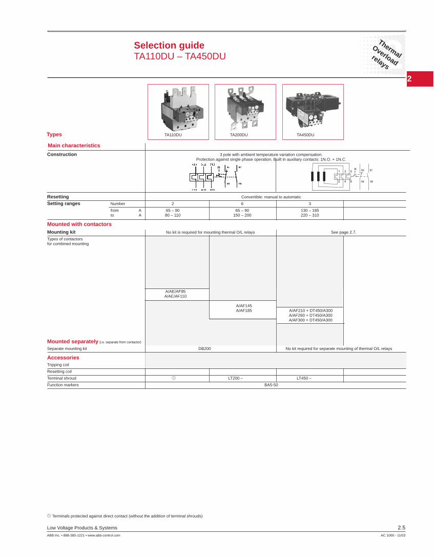
Selection guideTA110DU – TA450DU
Types TA110DU TA200DU TA450DU
Main characteristics
1 Terminals protected against direct contact (without the addition of terminal shrouds)
Construction 3 pole with ambient temperature variation compensation. Protection against single phase op er a tion. Built in auxiliary con tacts: 1N.O. + 1N.C.
Resetting Convertible: manual to automatic
Setting ranges Number 2 6 3
from A 65 – 90 65 – 90 130 – 185 to A 80 – 110 150 – 200 220 – 310
Mounted with contactorsMounting kit No kit is required for mounting ther mal O/L relays See page 2.7.
Types of contactors for combined mounting
A/AE/AF95 A/AE/AF110 A/AF145 A/AF185 A/AF210 + DT450/A300 A/AF260 + DT450/A300 A/AF300 + DT450/A300
Mounted separately (i.e. separate from contactor)
Separate mounting kit DB200 No kit required for separate mounting of thermal O/L relays
AccessoriesTripping coil
Resetting coil
Terminal shroud 1 LT200 – LT450 –
Function markers BA5-50
2
2Thermal
Overload
relays
2.6 Low Voltage Products & Systems
AC 1000 - 11/03 ABB Inc. • 888-385-1221 • www.abb-control.com
TA42DU
TA75DU
TA80DU
TA110DU
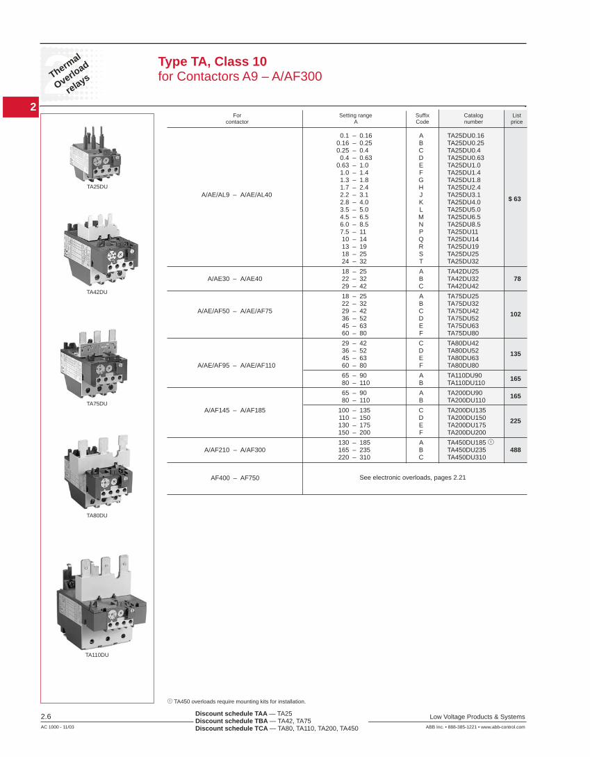
Type TA, Class 10for Contactors A9 – A/AF300
For Setting range Suffi x Catalog List contactor A Code number price
Discount schedule TAA — TA25 Discount schedule TBA — TA42, TA75 Discount schedule TCA — TA80, TA110, TA200, TA450
0.1 – 0.16 A TA25DU0.16 0.16 – 0.25 B TA25DU0.25 0.25 – 0.4 C TA25DU0.4 0.4 – 0.63 D TA25DU0.63 0.63 – 1.0 E TA25DU1.0 1.0 – 1.4 F TA25DU1.4 1.3 – 1.8 G TA25DU1.8 1.7 – 2.4 H TA25DU2.4 A/AE/AL9 – A/AE/AL40 2.2 – 3.1 J TA25DU3.1 2.8 – 4.0 K TA25DU4.0 $ 63
3.5 – 5.0 L TA25DU5.0 4.5 – 6.5 M TA25DU6.5 6.0 – 8.5 N TA25DU8.5 7.5 – 11 P TA25DU11 10 – 14 Q TA25DU14 13 – 19 R TA25DU19 18 – 25 S TA25DU25 24 – 32 T TA25DU32
18 – 25 A TA42DU25 A/AE30 – A/AE40 22 – 32 B TA42DU32 78 29 – 42 C TA42DU42
18 – 25 A TA75DU25 22 – 32 B TA75DU32 A/AE/AF50 – A/AE/AF75 29 – 42 C TA75DU42 102 36 – 52 D TA75DU52 45 – 63 E TA75DU63 60 – 80 F TA75DU80
29 – 42 C TA80DU42 36 – 52 D TA80DU52 135 45 – 63 E TA80DU63 A/AE/AF95 – A/AE/AF110 60 – 80 F TA80DU80
65 – 90 A TA110DU90 165 80 – 110 B TA110DU110
65 – 90 A TA200DU90 165 80 – 110 B TA200DU110
A/AF145 – A/AF185 100 – 135 C TA200DU135 110 – 150 D TA200DU150 225 130 – 175 E TA200DU175 150 – 200 F TA200DU200
130 – 185 A TA450DU185 1 A/AF210 – A/AF300 165 – 235 B TA450DU235 488 220 – 310 C TA450DU310
AF400 – AF750 See electronic overloads, pages 2.21
TA25DU
1 TA450 overloads require mounting kits for installation.
2
2Thermal
Overloadrelays
Low Voltage Products & Systems 2.7ABB Inc. • 888-385-1221 • www.abb-control.com AC 1000 - 11/03
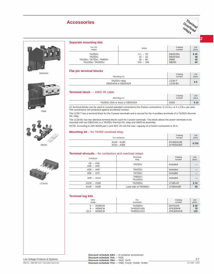
Accessories
DB25/25A
DB80
DB200
LC26-B1
Separate mounting kits
Flat pin terminal blocks
Terminal block — AWG #8 cable
TA25DU 0.1 – 25 DB25/25A $ 30 TA25DU 24 – 32 DB25/32A 38 TA42DU, TA75DU, TA80DU 18 – 80 DB80 45 TA110DU, TA200DU 100 – 200 DB200 60
For O/L Amps Catalog List relays number price
Catalog List Mounting on: number price
TA25DU (25A or less) or DB25/25A DX25 $ 15
Catalog List Mounting on: number price
TA25DU relay LC30-T $ 6 DB25/25A or DB25/32A LC26-B1
Mounting kit – for TA450 overload relay
A145 – A185 DT450/A185 $ 225 A210 – A300 DT450/A300
Catalog List For contactor number price
LC terminal blocks can be used to convert standard connections into Faston connections: 2 x 6.3mm or 4 x 2.8mm per pole. The connections are protected against accidental contact.
The LC30-T has a terminal block for the 3 power terminals and a second for the 4 auxiliary terminals of a TA25DU thermal O/L relay.
The LC26-B1 has two identical terminal blocks each for 3 power terminals. This block allows the power terminals to be mounted with two DB25 kits or a TA25DU thermal O/L relay and DB25 kit assembly.
NOTE: According to DIN 46429 part 1 and NFC 20-120 the max. capacity of a Faston connection is 25 A.
Terminal shrouds – for contactors and overload relays Overload Catalog List Contactor relay number price
A9 – A16 TA25DU Included — A26 – A40
A30 – A40 TA42DU Included —
A50 – A75 TA75DU Included —
A95 – A110 TA80DU Included — TA110DU
A145 – A185 TA200DU LT185-AY $ 10
A145 – A185 Load side of TA200DU LT200A185 50
Terminal lug kits Wire For Catalog List range overloads number price
6 – 250MCM TA200DU EHTK210 $ 45 4 – 400MCM TA450DU185 ATK300HK 78 (2) 4 – 500MCM TA450DU310 ATK300/2HK 120
Discount schedule ABA — A-contactor accessories Discount schedule TAA — TA25 Discount schedule TBA — TA42, TA75 Discount schedule TCA — TA80, TA110, TA200, TA450

2
2Thermal
Overload
relays
2.8 Low Voltage Products & Systems
AC 1000 - 11/03 ABB Inc. • 888-385-1221 • www.abb-control.com
23 24
13 14
HANDOFF
AUTO
M
13 14
A1 A2M95 96
O L
21 22
STOPSTART
13 14
E1 E2
OLTRIPPING
COIL
OVERLOADTRIP
L1 L2/N
A1 A2M96
O L
E1 E2
OLTRIPPING
COIL
OVERLOADTRIP
L1 L2/N
95 23 24
13 14
HANDOFF
AUTO
M
13 14
A1 A2M95 96
O L
21 22
STOPSTART
13 14
E1 E2
OLRESETTING
COIL
OVERLOADRESET
L1 L2/N
A1 A2M96
O L
E1 E2
OLRESETTING
COIL
OVERLOADRESET
L1 L2/N
95
97 98
O L
97 98
O L
1 Cannot be used with TA42, TA75, or TA200 overload relays.
DS25A
DR25A
Application• The DS25-A coil is used for remote electrical tripping of the TA25 DU thermal O/L relay and is connected to the relay's normally closed 95-96 auxiliary contact.
• The DR 25-A coil is used for remote electrical resetting of the TA25DU thermal O/L relay which isadjusted for “Manual resetting;” it is connected to the relayʼs normally open 97-98 auxiliary contact.
The coils are not designed for continuous duty. Impulse duration: 0.2 to 0.35 s.
Set the button to “Man” (Manual resetting).
Mounting: clipped on to TA25DU thermal O/L relay.
U voltage at 50/60 Hz Catalog List number 1 price
DS25-A remote tripping coil 24V DS25-A-24 48V DS25-A-48 110V DS25-A-110 220/380V DS25-A-220/380 500V DS25-A-500 $ 60DS25-A remote resetting coil 24V DR25-A-24 48V DR25-A-48 110V DR25-A-110 220/380V DR25-A-220/380 500V DR25-A-500
Installation diagrams
For connection of DS25-A to TA25DU relay For connection of DR25-A to TA25DU relay
Remote tripping coils
Discount schedule TAA — TA25
Accessories
2
2Thermal
Overloadrelays
Low Voltage Products & Systems 2.9ABB Inc. • 888-385-1221 • www.abb-control.com AC 1000 - 11/03
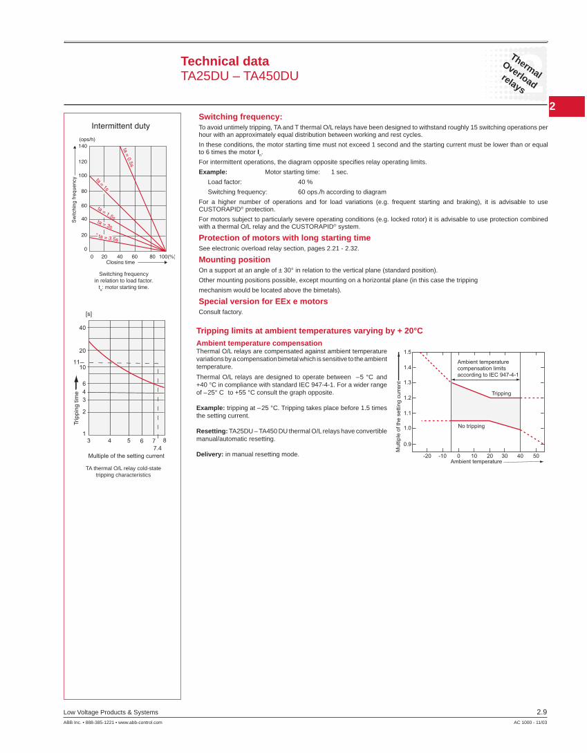
Switching frequency:To avoid untimely tripping, TA and T thermal O/L relays have been designed to withstand roughly 15 switching operations per hour with an approximately equal distribution between working and rest cycles.
In these conditions, the motor starting time must not exceed 1 second and the starting current must be lower than or equal to 6 times the motor In.
For intermittent operations, the diagram opposite specifi es relay operating limits.
Example: Motor starting time: 1 sec.
Load factor: 40 %
Switching frequency: 60 ops./h according to diagram
For a higher number of operations and for load variations (e.g. frequent starting and braking), it is advisable to use CUSTORAPID® protection.
For motors subject to particularly severe operating conditions (e.g. locked rotor) it is advisable to use protection combined with a thermal O/L relay and the CUSTORAPID® system.
Protection of motors with long starting timeSee electronic overload relay section, pages 2.21 - 2.32.
Mounting positionOn a support at an angle of ± 30° in relation to the vertical plane (standard position).
Other mounting positions possible, except mounting on a horizontal plane (in this case the tripping
mechanism would be located above the bimetals).
Special version for EEx e motorsConsult factory.
Tripping limits at ambient temperatures varying by + 20°C
0 20 40 60 80 100(%)Closing time
0
20
40
60
80
100
120
140
Switchingfrequency
(ops/h)
ta=0.5s
ta=1s
ta = 1.5sta = 3s
ta = 3.5s
Intermittent duty
Ambient temperaturecompensation limitsaccording to IEC 947-4-1
No tripping
Mul
tiple
ofth
ese
tting
curr
ent
Tripping
Ambient temperature-20 -10 0 10 20 30 40 50
0.9
1.0
1.1
1.2
1.3
1.4
1.5
40
20
1110
643
2
13 4 5 6 7
7.48
[s]
Multiple of the setting current
Trip
ping
time
Ambient temperature compensationThermal O/L relays are compensated against ambient temperature variations by a compensation bimetal which is sensitive to the ambient temperature.
Thermal O/L relays are designed to operate between –5 °C and +40 °C in compliance with standard IEC 947-4-1. For a wider range of –25° C to +55 °C consult the graph opposite.
Example: tripping at –25 °C. Tripping takes place before 1.5 times the setting current.
Resetting: TA25DU – TA450 DU thermal O/L relays have convertible manual/automatic resetting.
Delivery: in manual resetting mode.
Switching frequencyin relation to load factor.
ta: motor starting time.
TA thermal O/L relay cold-state tripping characteristics
Technical data TA25DU – TA450DU
2
2Thermal
Overload
relays
2.10 Low Voltage Products & Systems
AC 1000 - 11/03 ABB Inc. • 888-385-1221 • www.abb-control.com
A1A2
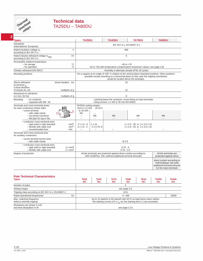
Technical dataTA25DU – TA80DU
Types TA25DU TA42DU TA75DU TA80DUStandards: IEC 947-4-1, EN 60947-4-1(international, European)
Rated insulation voltage Ui V 690according to IEC 947-4-1
Rated impulse withstand voltage Uimp kV 6according to IEC 947-4-1
Permissible ambient temperature – for storage °C –40 to +70 – for operation °C –25 to +55 with temperature compensation (maximum values: see page 2.9)
Climatic withstand DIN 50017 Humidity in alternate climate KFW, 30 cycles
Mounting positions On a support at an angle of ±30° in relation to the vertical plane (standard position). Other positions possible except mounting on a horizontal plane (in this case the tripping mechanism would be located above the bimetals).
Shock withstand shock duration ms 15at nominal Ie Critical directionof shocks A1, A2 multiples of g 12
Resistance to vibrations(±1 mm, 50 Hz) multiples of g 8
Mounting – on contactor Latching below the contactor, screw fi xing on main terminals – separate with DB - kit Using screws: 2 x M4 or 35 mm EN 50022
Terminals and cross-sectional areas TA25DU setting ranges:for main conductors (motor side) from 0.1-0.16A 24-32 A • screw terminal to 18-25A – with cable clamp M4 – – via tunnel connector – M5 M6 M6 M6 – fl at type for lug or bar – – – – –
• conductor cross-sectional area – rigid solid or rigid stranded mm2 2 x 1.5 - 6 1 x 10 1 x 2.5 - 35 or 2 x 2.5 x 16 – fl exible with cable end mm2 2 x 1.5 - 4 2 x 0.75- 6 1 x 2.5 - 25 or 2 x 2.5 x 10 – recommended bars mm – – – – –
Terminals and cross-sectional areafor auxiliary conductors
• screw terminal (screw size) – with cable clamp M 3.5
• conductor cross-sectional area – rigid solid or rigid stranded 2 x mm2 0.75 - 4 – fl exible with cable end 2 x mm2 0.75 - 2.5
Degree of protection All the terminals are protected against direct contact according to All the terminals are VDE 0106/Part. 100. (without additional terminal shrouds) protected against direct
direct contact according to VDE0106/part 100 (with additional terminal shrouds for the main terminals
Pole Technical CharacteristicsTypes TA25 TA42 TA75 TA80 TA10 TA200 TA450 DU DU DU DU DU DU DU
Number of poles 3
Setting ranges see page 2.6
Tripping class according to IEC 947-4-1, EN 60947-1 10 A
Rated operational frequencies Hz 0 - 400 50/60
Max. switching frequency Up to 15 starts/h or 60 starts/h with 40 % on-load factor when neitherwithout untimely tripping the starting current of 6 x In nor the starting time 1 s are exceeded.
Resistance per phase in mΩand heat dissipation in W see page 2.13
2
2Thermal
Overloadrelays
Low Voltage Products & Systems 2.11ABB Inc. • 888-385-1221 • www.abb-control.com AC 1000 - 11/03
A1A2
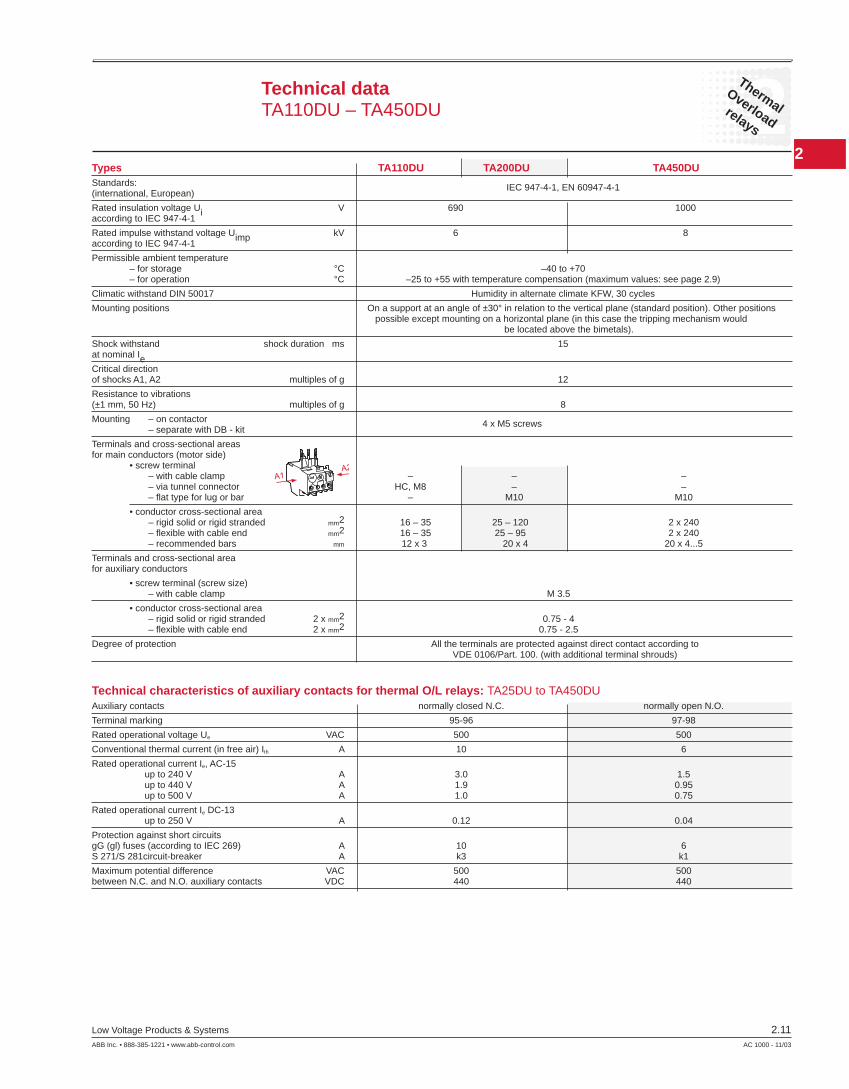
Technical dataTA110DU – TA450DU
Types TA110DU TA200DU TA450DUStandards: IEC 947-4-1, EN 60947-4-1(international, European)
Rated insulation voltage Ui V 690 1000according to IEC 947-4-1
Rated impulse withstand voltage Uimp kV 6 8according to IEC 947-4-1
Permissible ambient temperature – for storage °C –40 to +70 – for operation °C –25 to +55 with temperature compensation (maximum values: see page 2.9)
Climatic withstand DIN 50017 Humidity in alternate climate KFW, 30 cycles
Mounting positions On a support at an angle of ±30° in relation to the vertical plane (standard position). Other positions possible except mounting on a horizontal plane (in this case the tripping mechanism would be located above the bimetals).
Shock withstand shock duration ms 15at nominal Ie
Critical directionof shocks A1, A2 multiples of g 12
Resistance to vibrations(±1 mm, 50 Hz) multiples of g 8
Mounting – on contactor 4 x M5 screws – separate with DB - kit
Terminals and cross-sectional areas for main conductors (motor side) • screw terminal – with cable clamp – – – – via tunnel connector HC, M8 – – – fl at type for lug or bar – M10 M10
• conductor cross-sectional area – rigid solid or rigid stranded mm2 16 – 35 25 – 120 2 x 240 – fl exible with cable end mm2 16 – 35 25 – 95 2 x 240 – recommended bars mm 12 x 3 20 x 4 20 x 4...5
Terminals and cross-sectional areafor auxiliary conductors
• screw terminal (screw size) – with cable clamp M 3.5
• conductor cross-sectional area – rigid solid or rigid stranded 2 x mm2 0.75 - 4 – fl exible with cable end 2 x mm2 0.75 - 2.5
Degree of protection All the terminals are protected against direct contact according to VDE 0106/Part. 100. (with additional terminal shrouds)
Technical characteristics of auxiliary contacts for thermal O/L relays: TA25DU to TA450DUAuxiliary contacts normally closed N.C. normally open N.O.
Terminal marking 95-96 97-98
Rated operational voltage Ue VAC 500 500
Conventional thermal current (in free air) Ith A 10 6
Rated operational current Ie, AC-15 up to 240 V A 3.0 1.5 up to 440 V A 1.9 0.95 up to 500 V A 1.0 0.75
Rated operational current Ie DC-13 up to 250 V A 0.12 0.04
Protection against short circuitsgG (gl) fuses (according to IEC 269) A 10 6S 271/S 281circuit-breaker A k3 k1
Maximum potential difference VAC 500 500between N.C. and N.O. auxiliary contacts VDC 440 440
2
2Thermal
Overload
relays
2.12 Low Voltage Products & Systems
AC 1000 - 11/03 ABB Inc. • 888-385-1221 • www.abb-control.com
M3~
M3~
M3~
M3~
SPEM
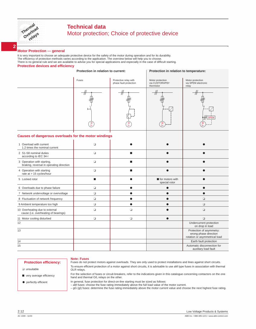
Technical dataMotor protection; Choice of protective device
Motor Protection — generalIt is very important to choose an adequate protective device for the safety of the motor during operation and for its durability.The effi ciency of protection methods varies according to the application. The overview below will help you to choose.There is no general rule and we are available to advise you for special applications and especially in the case of diffi cult starting.
Protective devices and effi ciency Protection in relation to current: Protection in relation to temperature:
Fuses Protective relay with Motor protection Motor protection phase fault protection via CUSTORAPID® via SPEM electronic thermistor relay
Causes of dangerous overloads for the motor windings
1 Overload with current 1.2 times the nominal current
2 S1-S8 nominal duties according to IEC 34-I
3 Operation with starting, braking, reversal in operating direction
4 Operation with starting rate at > 15 cycles/hour
5 Locked rotor for motors with special rotor
6 Overloads due to phase failure
7 Network undervoltage or overvoltage
8 Fluctuation of network frequency
9 Ambient temperature too high
10 Overheating due to external cause (i.e. overheating of bearings)
11 Motor cooling disturbed
12 Undercurrent protection on drop in load
13 Protection of asymmetry: wrong phase direction rotation or asymmetrical load
14 Earth fault protection
15 Automatic disconnection for auxiliary load fault
Note: FusesFuses do not protect motors against overloads. They are only used to protect installations and lines against short circuits.
To ensure effi cient protection of a motor against short circuits, it is advisable to use aM type fuses in association with thermal OLR relays.
For the selection of fuses or circuit-breakers, refer to the indications given in this catalogue concerning contactors on the one hand and thermal O/L relays on the other.
In general, fuse protection for direct-on-line starting must be sized as follows:– aM fuses: choose the fuse rating immediately above the full load value of the motor current.– gG (gI) fuses: determine the fuse rating immediately above the motor current value and choose the next highest fuse rating.
Protection effi ciency:
unsuitable
very average effi ciency
perfectly effi cient

2
2Thermal
Overloadrelays
Low Voltage Products & Systems 2.13ABB Inc. • 888-385-1221 • www.abb-control.com AC 1000 - 11/03
Resistance and Joule losses per phase, short circuit protection
Joule losses Setting range Resistance per phase at current per phase max. setting from – to A A mΩ W
TA25DU 0.1 – 0.16 85850 2.2 0.16 – 0.25 85150 2.2 0.25 – 0.4 13750 2.2
0.4 – 0.63 5370 2.2 0.63 – 1.0 2190 2.2 1.0 – 1.4 1120 2.2
1.3 – 1.8 670 2.2 1.7 – 2.4 383 2.2 2.2 – 3.1 229 2.2
2.8 – 4.0 137 2.2 3.5 – 5.0 87.5 2.2 4.5 – 6.5 61 2.2
6.0 – 8.5 30.4 2.2 7.5 – 11 18.2 2.2 10 – 14 11.2 2.2 13 – 19 6.3 2.3 18 – 25 4.7 2.9 24 – 32 3.2 3.3
TA42DU 18 – 25 5.5 3.43 22 – 32 2.89 2.91 29 – 42 1.84 3.24
TA75DU 18 – 25 5.5 3.43 22 – 32 2.89 2.91 29 – 42 1.84 3.24 36 – 52 1.3 3.51 45 – 63 0.936 3.72 60 – 80 0.615 3.94
TA80DU 29 – 42 1.84 3.24 36 – 52 1.3 3.51 45 – 63 0.936 3.72 60 – 80 0.615 3.94
Joule losses Setting range Resistance per phase at current per phase max. setting from – to A A mΩ W
TA110DU 80 – 110 0.378 3.78
TA200DU 100 – 135 0.318 5.79 110 – 150 0.255 5.74 130 – 175 0.214 6.55 150 – 200 0.182 7.28
TA450DU 130 – 185 — 2.5 165 – 235 — 2.5 220 – 310 — 2.5
Technical dataResistance and Joule losses per phaseShort circuit protection
2
2Thermal
Overload
relays
2.14 Low Voltage Products & Systems
AC 1000 - 11/03 ABB Inc. • 888-385-1221 • www.abb-control.com
Trip
ping
time
Min
utes
Tripping currentin multiples of the setting current
Sec
onds
1201008060
40
40
20
20
10
10
8
8
6
86
4
4
2
2
1
1
0.8 1 2 3 4 5 6 7 8 9 101.2 1.5
from warm state
from cold state
3 Phases
3 Phases2 Phases
2 Phases
Trip
ping
time
Min
utes
Tripping currentin multiples of the setting current
Sec
onds
1201008060
40
40
20
20
10
10
8
8
6
86
4
4
2
2
1
1
0.8 1 2 3 4 5 6 7 8 9 101.2 1.5
from warm state
from cold state
3 Phases
3 Phases
2 Phases
2 Phases
Trip
ping
time
Min
utes
Tripping currentin multiples of the setting current
Sec
onds
1201008060
40
40
20
20
10
10
8
8
6
86
4
4
2
2
1
1
0.8 1 2 3 4 5 6 7 8 9 101.2 1.5
from warm state
from cold state
3 Phases
3 Phases
2 Phases
2 Phases
6
8
0.8 1 1.2 1.5 2 3 4 5 6 7 8 9 101
2
4
810
20
40
1
2
4
6
10
20
40
6080
100120
from warm state
from cold state
3 Phases
3 Phases
2 Phases
2 Phases
Trip
ping
time
Min
utes
Tripping currentin multiples of the setting current
Sec
onds
6
8
0.8 1 1.2 1.5 2 3 4 5 6 7 8 9 10
Tripping currentas multiple of setting current
1
2
4
810
20
40
1
2
4
6
10
20
40
6080
100120
Trip
ing
time m
inut
esse
cond
s
from warm state
from cold state
2 Phase
3 Phase
2 Phase
3 Phase
TA200DU TA450DU(tripping class 10A) (tripping class 10A)
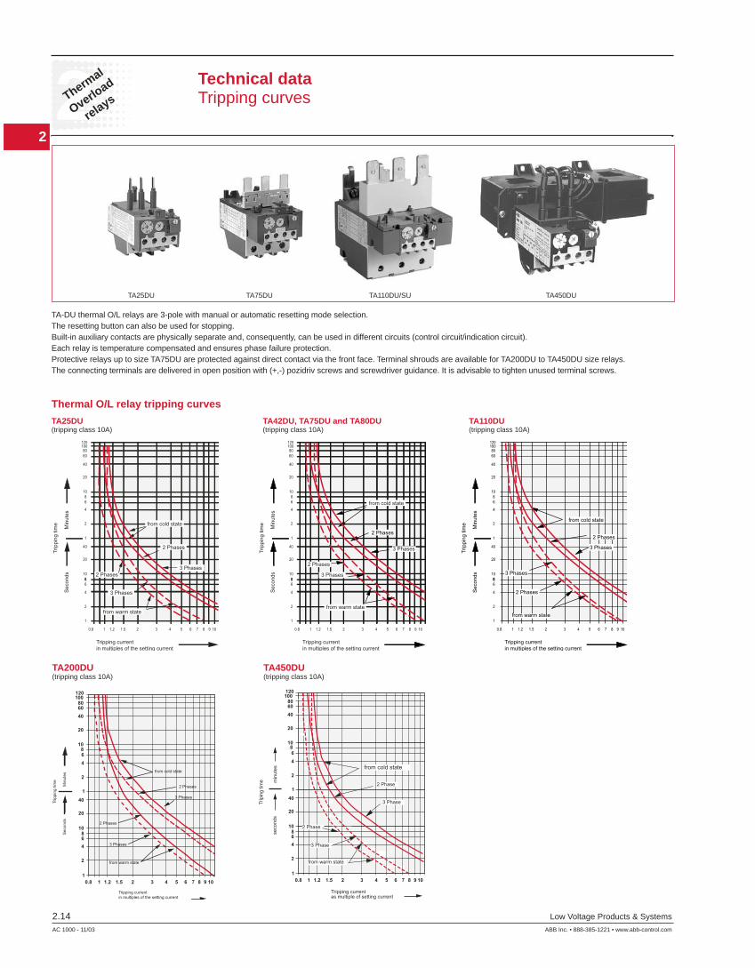
Technical data Tripping curves
TA25DU TA75DU TA110DU/SU TA450DU
Thermal O/L relay tripping curves
TA25DU TA42DU, TA75DU and TA80DU TA110DU (tripping class 10A) (tripping class 10A) (tripping class 10A)
TA-DU thermal O/L relays are 3-pole with manual or automatic resetting mode selection.The resetting button can also be used for stopping. Built-in auxiliary contacts are physically separate and, consequently, can be used in different circuits (control circuit/indication circuit). Each relay is temperature compensated and ensures phase failure protection. Protective relays up to size TA75DU are protected against direct contact via the front face. Terminal shrouds are available for TA200DU to TA450DU size relays. The connecting terminals are delivered in open position with (+,-) pozidriv screws and screwdriver guidance. It is advisable to tighten unused terminal screws.
2
2Thermal
Overloadrelays
Low Voltage Products & Systems 2.15ABB Inc. • 888-385-1221 • www.abb-control.com AC 1000 - 11/03
00.0000.00
Inches[Millimeters]
0.24
3.7094
0.5113
3.1580
1.7344
3.7094
6
TA25DU32only
3.5490
0.246
4.35110.5
2.1354
0.5113
3.3184
1.7344
0.356
4.25108
0.246
0.5113
1.3835
1.8848
4.20.17
1.3835
1.8848
4.20.17
0.356
4.25108
0.246
0.5113
1.7344
4.41112
0.5113
3.8698
2.3660
5.03127.7
0.246
1.9750
2.9575
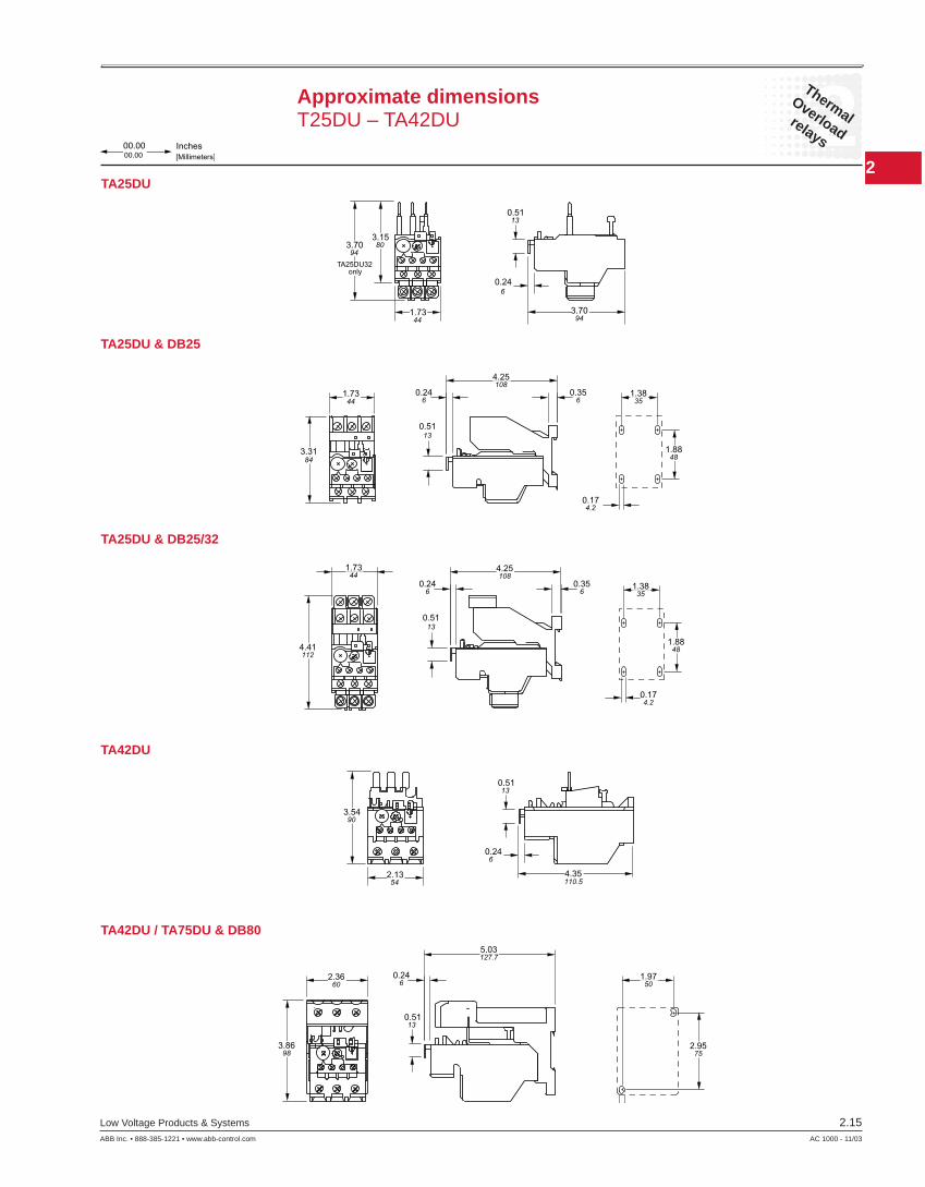
Approximate dimensionsT25DU – TA42DU
TA25DU
TA42DU
TA25DU & DB25
TA25DU & DB25/32
TA42DU / TA75DU & DB80
2
2Thermal
Overload
relays
2.16 Low Voltage Products & Systems
AC 1000 - 11/03 ABB Inc. • 888-385-1221 • www.abb-control.com
3.9993
2.1354
0.246
4.35110.5
0.5113
6 - 0.21 HOLES
2.5264.0
0.246.0
.6115.5
1.9850.2
1.4837.5
3.1480.0
5.44138.1
TOUCH SAFE COVER
4.73120.1
0.246.0
0.071.7
1.18
2 - M4 Mtg. Slots
30.00.4712.0
0.4712.0
3.77
2.85
54.0
95.7
72.3
4.37
0.5012.5
111.0
TOUCH SAFE COVER
2.12
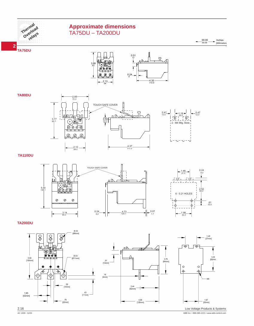
TA200DU
00.0000.00
Inches[Millimeters]
Approximate dimensions TA75DU – TA200DU
TA75DU
TA80DU
TA110DU
2
2Thermal
Overloadrelays
Low Voltage Products & Systems 2.17ABB Inc. • 888-385-1221 • www.abb-control.com AC 1000 - 11/03
168.0
4.5
58.0 58.0
21.0
28.3
0.18
6.62
2.282.28
1.11
0.82
6.0 76.0
24.5
55.0
193.0
2.17
0.96
7.60
0.24 2.99
5.0 DIA.0.2 DIA.
642
00.0000.00
Inches[Millimeters]
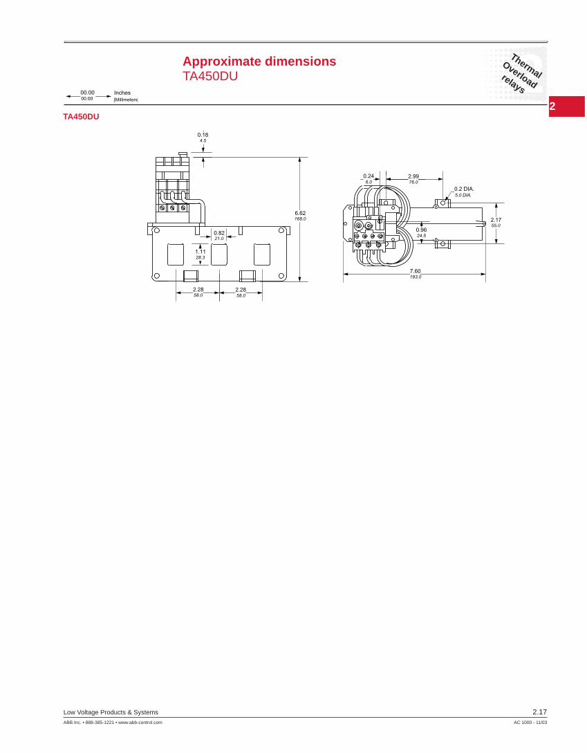
Approximate dimensions TA450DU
TA450DU

2
2Thermal
Overload
relays
2.18 Low Voltage Products & Systems
AC 1000 - 11/03 ABB Inc. • 888-385-1221 • www.abb-control.com
Notes
2
2Electronic
Overloadrelays
Low Voltage Products & Systems 2.19ABB Inc. • 888-385-1221 • www.abb-control.com AC 1000 - 11/03
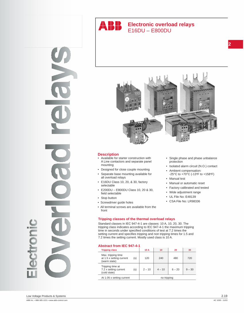
Electronic overload relaysE16DU – E800DU
Description• Available for starter construction with
A Line contactors and separate panel mounting
• Designed for close couple mounting
• Separate base mounting available for all overload relays
• E16DU Class 10, 20, & 30, factory selectable
• E200DU – E800DU Class 10, 20 & 30, fi eld selectable
• Stop button
• Screwdriver guide holes
• All terminal screws are available from the front
• Single phase and phase unbalance protection
• Isolated alarm circuit (N.O.) contact
• Ambient compensation: -25°C to +70°C (-13oF to +158oF)
• Manual test
• Manual or automatic reset
• Factory calibrated and tested
• Wide adjustment range
• UL File No: E48139
• CSA File No: LR98336
Tripping classes of the thermal overload relaysStandard classes in IEC 947-4-1 are classes: 10 A, 10, 20, 30. The tripping class indicates according to IEC 947-4-1 the maximum tripping time in seconds under specifi ed conditions of test at 7.2 times the setting current and specifi es tripping and non tripping times for 1.5 and 7.2 times the setting current. Mostly used class is 10 A.
Abstract from IEC 947-4-1Tripping class 10 A 10 20 30
Max. tripping timeat 1.5 x setting current (s) 120 240 480 720(warm state)
Tripping time at7.2 x setting current (s) 2 – 10 4 – 10 6 – 20 9 – 30(cold state)
At 1.05 x setting current no tripping

2
2Electronic
Overload
relays
2.20 Low Voltage Products & Systems
AC 1000 - 11/03 ABB Inc. • 888-385-1221 • www.abb-control.com
Nominal current setting
Stop button
Reset, manual or automatic
Trip indicator test function
General informationCatalog number explanation
Frame sizeE16DUE200DUE320DUE500DUE800DU
Amp rating1.0200320500800
Catalog number explanation
E16DU 1.0 10Class size102030
2
2Electronic
Overloadrelays
Low Voltage Products & Systems 2.21ABB Inc. • 888-385-1221 • www.abb-control.com AC 1000 - 11/03
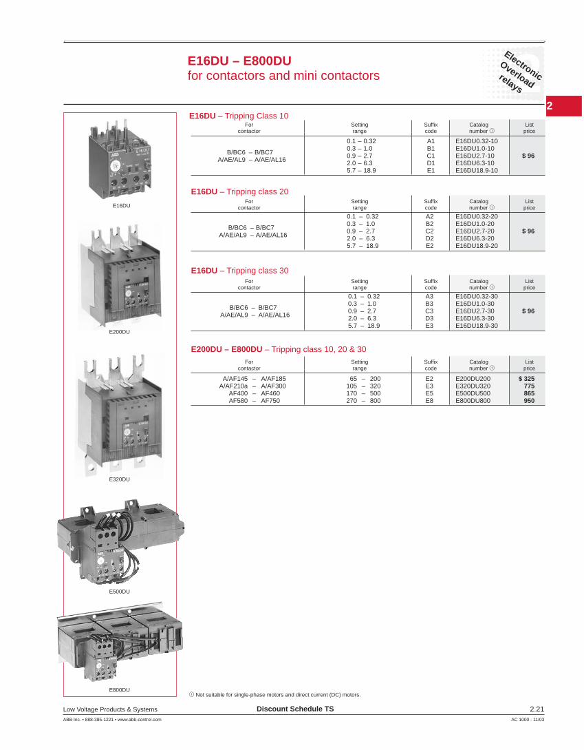
E16DU – E800DUfor contactors and mini contactors
E16DU
E16DU – Tripping Class 10
0.1 – 0.32 A1 E16DU0.32-10
B/BC6 – B/BC7 0.3 – 1.0 B1 E16DU1.0-10
A/AE/AL9 – A/AE/AL16
0.9 – 2.7 C1 E16DU2.7-10 $ 96 2.0 – 6.3 D1 E16DU6.3-10 5.7 – 18.9 E1 E16DU18.9-10
For Setting Suffi x Catalog List contactor range code number 1 price
E16DU – Tripping class 20
0.1 – 0.32 A2 E16DU0.32-20
B/BC6 – B/BC7 0.3 – 1.0 B2 E16DU1.0-20
A/AE/AL9 – A/AE/AL16
0.9 – 2.7 C2 E16DU2.7-20 $ 96 2.0 – 6.3 D2 E16DU6.3-20 5.7 – 18.9 E2 E16DU18.9-20
Discount Schedule TS
1 Not suitable for single-phase motors and direct current (DC) motors.
E16DU – Tripping class 30
0.1 – 0.32 A3 E16DU0.32-30
B/BC6 – B/BC7 0.3 – 1.0 B3 E16DU1.0-30
A/AE/AL9 – A/AE/AL16
0.9 – 2.7 C3 E16DU2.7-30 $ 96 2.0 – 6.3 D3 E16DU6.3-30 5.7 – 18.9 E3 E16DU18.9-30
E200DU – E800DU – Tripping class 10, 20 & 30
A/AF145 – A/AF185 65 – 200 E2 E200DU200 $ 325 A/AF210a – A/AF300 105 – 320 E3 E320DU320 775 AF400 – AF460 170 – 500 E5 E500DU500 865 AF580 – AF750 270 – 800 E8 E800DU800 950
E200DU
E320DU
E500DU
E800DU
For Setting Suffi x Catalog List contactor range code number 1 price
For Setting Suffi x Catalog List contactor range code number 1 price
For Setting Suffi x Catalog List contactor range code number 1 price
2
2Electronic
Overload
relays
2.22 Low Voltage Products & Systems
AC 1000 - 11/03 ABB Inc. • 888-385-1221 • www.abb-control.com
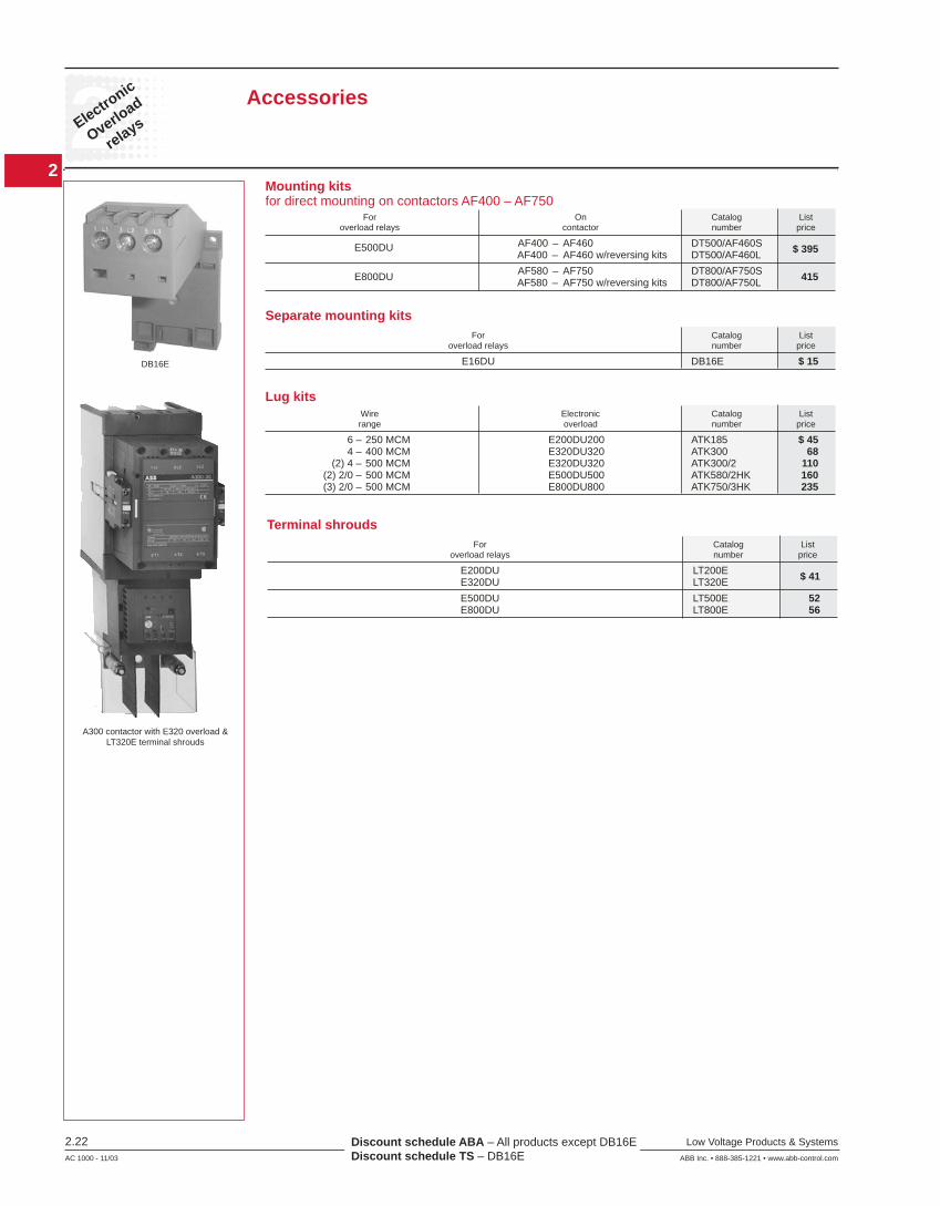
Accessories
Mounting kitsfor direct mounting on contactors AF400 – AF750
E500DU AF400 – AF460 DT500/AF460S $ 395 AF400 – AF460 w/reversing kits DT500/AF460L
E800DU AF580 – AF750 DT800/AF750S 415 AF580 – AF750 w/reversing kits DT800/AF750L
For On Catalog List overload relays contactor number price
Separate mounting kits
E16DU DB16E $ 15
For Catalog List overload relays number price
Lug kits
6 – 250 MCM E200DU200 ATK185 $ 45 4 – 400 MCM E320DU320 ATK300 68 (2) 4 – 500 MCM E320DU320 ATK300/2 110 (2) 2/0 – 500 MCM E500DU500 ATK580/2HK 160 (3) 2/0 – 500 MCM E800DU800 ATK750/3HK 235
Wire Electronic Catalog List range overload number price
DB16E
Discount schedule ABA – All products except DB16E Discount schedule TS – DB16E
Terminal shrouds
E200DU LT200E $ 41 E320DU LT320E
E500DU LT500E 52 E800DU LT800E 56
For Catalog List overload relays number price
A300 contactor with E320 overload <320E terminal shrouds
2
2Electronic
Overloadrelays
Low Voltage Products & Systems 2.23ABB Inc. • 888-385-1221 • www.abb-control.com AC 1000 - 11/03
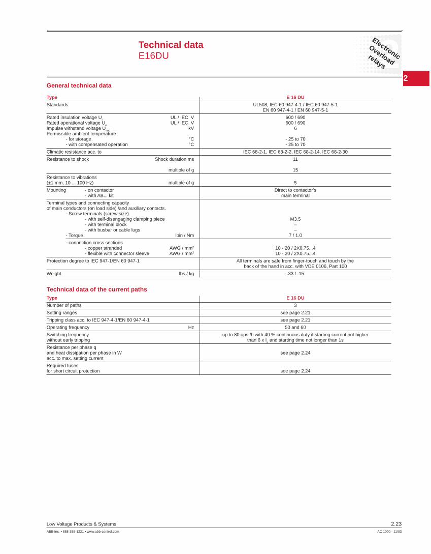
Technical dataE16DU
General technical data Type E 16 DU
Standards: UL508, IEC 60 947-4-1 / IEC 60 947-5-1 EN 60 947-4-1 / EN 60 947-5-1
Rated insulation voltage Ui UL / IEC V 600 / 690Rated operational voltage Ue UL / IEC V 600 / 690Impulse withstand voltage Uimp kV 6Permissible ambient temperature - for storage °C - 25 to 70 - with compensated operation °C - 25 to 70
Climatic resistance acc. to IEC 68-2-1, IEC 68-2-2, IEC 68-2-14, IEC 68-2-30
Resistance to shock Shock duration ms 11 multiple of g 15
Resistance to vibrations (±1 mm, 10 ... 100 Hz) multiple of g 5
Mounting - on contactor Direct to contactorʼs - with AB... kit main terminal
Terminal types and connecting capacityof main conductors (on load side) /and auxiliary contacts. - Screw terminals (screw size) - with self-disengaging clamping piece M3.5 - with terminal block – - with busbar or cable lugs – - Torque lbin / Nm 7 / 1.0
- connection cross sections - copper stranded AWG / mm2 10 - 20 / 2X0.75...4 - fl exible with connector sleeve AWG / mm2 10 - 20 / 2X0.75...4
Protection degree to IEC 947-1/EN 60 947-1 All terminals are safe from fi nger-touch and touch by the back of the hand in acc. with VDE 0106, Part 100
Weight lbs / kg .33 / .15
Technical data of the current paths
Type E 16 DU
Number of paths 3
Setting ranges see page 2.21
Tripping class acc. to IEC 947-4-1/EN 60 947-4-1 see page 2.21
Operating frequency Hz 50 and 60
Switching frequency up to 80 ops./h with 40 % continuous duty if starting current not higherwithout early tripping than 6 x In and starting time not longer than 1s
Resistance per phase qand heat dissipation per phase in W see page 2.24 acc. to max. setting current
Required fuses for short circuit protection see page 2.24
2
2Electronic
Overload
relays
2.24 Low Voltage Products & Systems
AC 1000 - 11/03 ABB Inc. • 888-385-1221 • www.abb-control.com
Tripping currentAs multiples of setting current
0.8 1 1.2 1.5 2 3 4 5 6 7 8 9 101
2
4
68
10
20
40
Class 30
1201008060
Sec
on
ds
Min
ute
s
Trip
pin
gti
me
2
4
68
10
20
40
1
Class 20
Class 10
3 phasefrom cold state
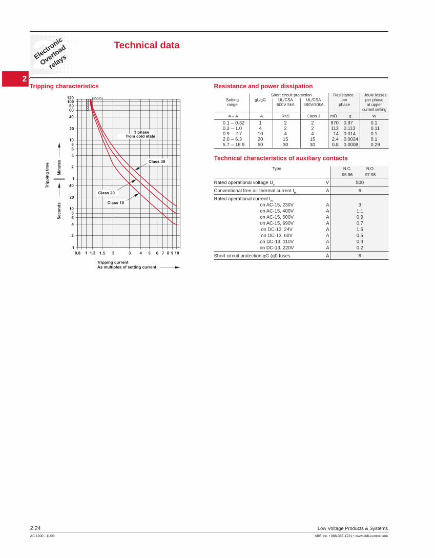
Tripping characteristics
Technical data
Resistance and power dissipation
0.1 – 0.32 1 2 2 970 0.97 0.1 0.3 – 1.0 4 2 2 113 0.113 0.11 0.9 – 2.7 10 4 4 14 0.014 0.1 2.0 – 6.3 20 15 15 2.4 0.0024 0.1 5.7 – 18.9 50 30 30 0.8 0.0008 0.29
Short circuit protection Resistance Joule losses Setting gL/gG UL/CSA UL/CSA per per phase range 600V 5kA 480V/50kA phase at upper current setting
A – A A RK5 Class J mΩ q W
Technical characteristics of auxiliary contacts
Type N.C. N.O.
95-96 97-98
Rated operational voltage Ue V 500
Conventional free air thermal current Ith A 6
Rated operational current Ith
on AC-15, 230V A 3 on AC-15, 400V A 1.1 on AC-15, 500V A 0.9 on AC-15, 690V A 0.7 on DC-13, 24V A 1.5 on DC-13, 60V A 0.5 on DC-13, 110V A 0.4 on DC-13, 220V A 0.2
Short circuit protection gG (gf) fuses A 6
2
2Electronic
Overloadrelays
Low Voltage Products & Systems 2.25ABB Inc. • 888-385-1221 • www.abb-control.com AC 1000 - 11/03
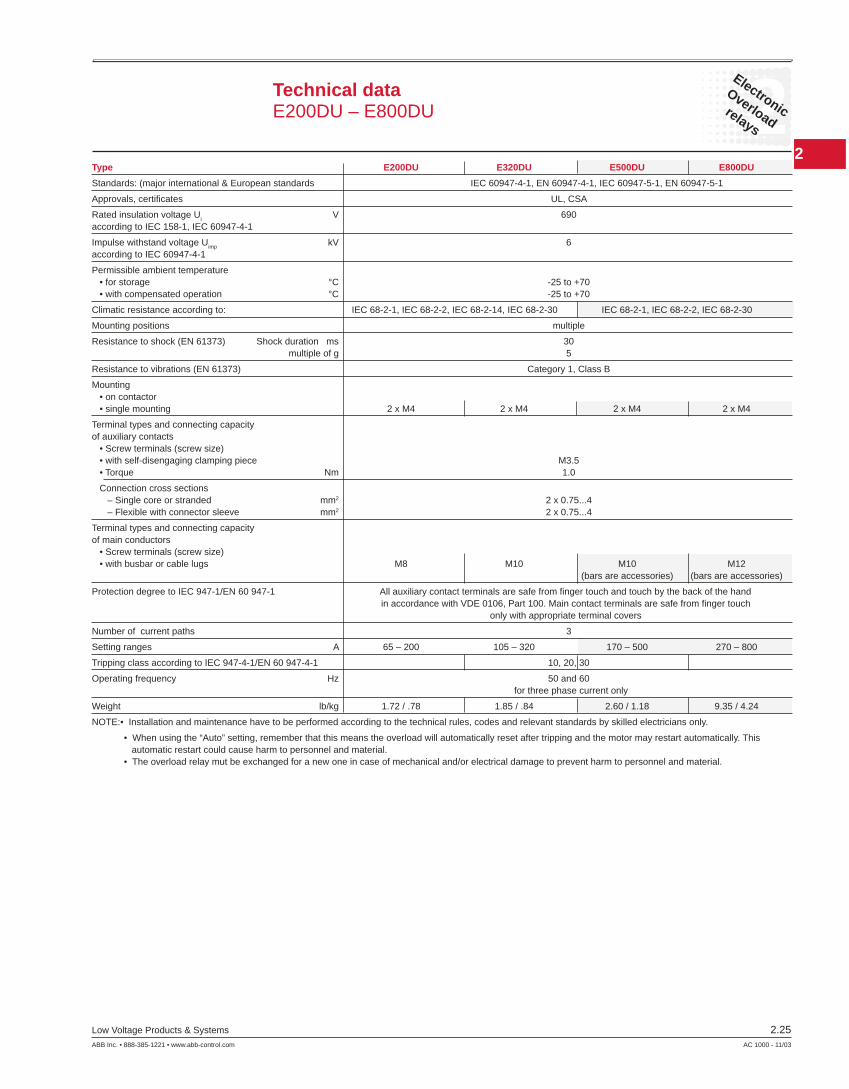
Technical dataE200DU – E800DU
Type E200DU E320DU E500DU E800DU
Standards: (major international & European standards IEC 60947-4-1, EN 60947-4-1, IEC 60947-5-1, EN 60947-5-1
Approvals, certifi cates UL, CSA
Rated insulation voltage Ui V 690according to IEC 158-1, IEC 60947-4-1
Impulse withstand voltage Uimp kV 6according to IEC 60947-4-1
Permissible ambient temperature • for storage °C -25 to +70 • with compensated operation °C -25 to +70
Climatic resistance according to: IEC 68-2-1, IEC 68-2-2, IEC 68-2-14, IEC 68-2-30 IEC 68-2-1, IEC 68-2-2, IEC 68-2-30
Mounting positions multiple
Resistance to shock (EN 61373) Shock duration ms 30 multiple of g 5
Resistance to vibrations (EN 61373) Category 1, Class B
Mounting • on contactor • single mounting 2 x M4 2 x M4 2 x M4 2 x M4
Terminal types and connecting capacityof auxiliary contacts • Screw terminals (screw size) • with self-disengaging clamping piece M3.5 • Torque Nm 1.0
Connection cross sections – Single core or stranded mm2 2 x 0.75...4 – Flexible with connector sleeve mm2 2 x 0.75...4
Terminal types and connecting capacityof main conductors • Screw terminals (screw size) • with busbar or cable lugs M8 M10 M10 M12 (bars are accessories) (bars are accessories)
Protection degree to IEC 947-1/EN 60 947-1 All auxiliary contact terminals are safe from fi nger touch and touch by the back of the hand in accordance with VDE 0106, Part 100. Main contact terminals are safe from fi nger touch only with appropriate terminal covers
Number of current paths 3
Setting ranges A 65 – 200 105 – 320 170 – 500 270 – 800
Tripping class according to IEC 947-4-1/EN 60 947-4-1 10, 20, 30
Operating frequency Hz 50 and 60 for three phase current only
Weight lb/kg 1.72 / .78 1.85 / .84 2.60 / 1.18 9.35 / 4.24
NOTE:• Installation and maintenance have to be performed according to the technical rules, codes and relevant standards by skilled electricians only.
• When using the “Auto” setting, remember that this means the overload will automatically reset after tripping and the motor may restart automatically. This automatic restart could cause harm to personnel and material. • The overload relay mut be exchanged for a new one in case of mechanical and/or electrical damage to prevent harm to personnel and material.
2
2Electronic
Overload
relays
2.26 Low Voltage Products & Systems
AC 1000 - 11/03 ABB Inc. • 888-385-1221 • www.abb-control.com
Technical dataTerms and technical defi nitions
AltitudeCharacterizes the place of use. It is expressed in meters above sea level.
Circuits • Auxiliary circuit – all the conductive parts of a contactor designed
to be inserted in a different circuit from the main circuit and the contactor control circuits.
• Control circuit – all the conductive parts of a contactor (other than the main circuit and the auxiliary circuit) used to control the contactorʼs closing operation or opening operation or both.
• Main circuit – all the conductive parts of a contactor designed to be inserted in the circuit that it controls.
Insulation Class according to NFC 20 040 and VDE 0110Characterizes adaptation of the devices to ambient temperature and operating conditions. For given clearances and creepage distances, a device will have different insulating voltages depending on insulation classes A, B, C & D. Class C corresponds to most industrial applications. The devices in this catalog belong to Class C.
Coordination of equipment protections during a short circuitThis is the addition upstream of the contactor and thermal overload relay of a short circuit (SCPD) protection device such as a circuit breaker, a fuse with a high breaking capacity or other fuses.
IEC publication 947-4-1 defi nes coordination Types 1 & 2:
• Type 1 – Coordination requires that, in the event of a short circuit, the contactor or starter does not endanger persons or installations and will not be able to operate without being repaired or parts being replaced.
• Type 2 – Coordination requires that, in short circuit conditions, the contactor or starter does not endanger persons or installations and will be able to operate afterwards. The risk of contacts being welded is acceptable. In this case, the manufacturer must stipulate the measures to be taken with respect to maintenance of the equipment.
Rated operational current IeCurrent rated by the manufacturer. It is mainly based on the rated
operational voltage Ue, the rated frequency, the utilization category, the rated duty and the type of protective enclosure, if necessary.
Conventional free air thermal current IthCurrent that the contactor can withstand in free air for a duty time of 8
hours without the temperature rise of its various parts exceeding the maximum values given by the standard.
Cycle timeCycle time is the sum of the current fl ow time and the no-current time for
given cycle.
Electrical durabilityNumber of on-load operations that the contactor is able to carry out; it
depends on the utilization category.
Mechanical durabilityNumber of no-current operations that a contactor is able to carry out.
Load factorRatio of the on-load operating time to the total cycle time x 100.
Switching frequencyNumber of switching cycles per hour.
2
2Electronic
Overloadrelays
Low Voltage Products & Systems 2.27ABB Inc. • 888-385-1221 • www.abb-control.com AC 1000 - 11/03
44
75
17
75
54.5
63.5 57
.5
128
15 18
7
44
1.73
2.15
2.5 2.
26 5.04
.59 .71
.28
1.73
2.95
0.672.95
9.3
2.41.2
9.3
44.4
74.6
148.2 5.65
10.3
36.3
37.5
53
57
4.4
14.8
44.6 68.5
35.7
41.7
5.514 14
69.5
65.2
64.5
50
82.7
91.1
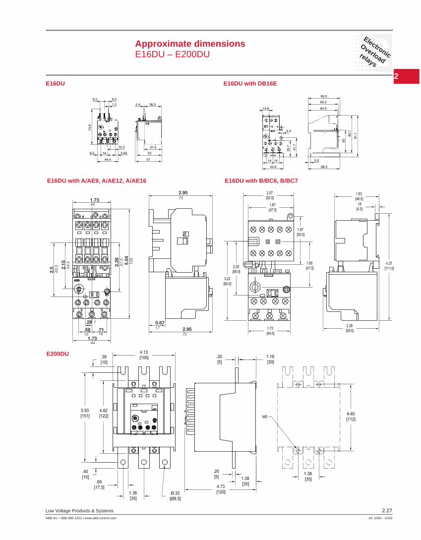
E16DU with A/AE9, A/AE12, A/AE16 E16DU with B/BC6, B/BC7
Approximate dimensionsE16DU – E200DU
E200DU
E16DU E16DU with DB16E

2
2Electronic
Overload
relays
2.28 Low Voltage Products & Systems
AC 1000 - 11/03 ABB Inc. • 888-385-1221 • www.abb-control.com
E800DU
Approximate dimensionsE320DU – E800DU
E320DU
E500DU