Embed Size (px)
Citation preview
Overlay SDN SolutionsAdvanced Computer Network Technologies
Petr Grygarek, 2017
What “Software Defined” Networks Actually Mean ?• SDN acronym is a buzzword used for lot of things today• Anyway, what is commonly expected from a SDN is
• agility: fast and efficient creation/modification/deletion of logical (multitenant) network topologies based on API calls
• decoupling of logical topologies from physical infrastructure• actually the same what happened to compute and storage in last years• easy integration with network services
• API-driven service insertion/chaining• support for 3rd party service implementations
• Overlay (=another layer of abstraction) is a natural way to implement the above requirements
• Tight integration with server virtualization platform (management, control & monitoring) is what is expected in today’s cloud-like automated solutions
Hardware and Software SDN Overlay
• Hardware-based solutions are pushed by network device manufacturers• emphasizes effectiveness of optimized hardware platforms for encapsulation
translation and identity to location search operations
• Software-based solutions are pushed by developers of virtualization platforms• emphasizes flexibility and lower server-based hardware costs• with increasing computational power of multicore multithreaded server
platforms, we can afford to accomplish many tasks traditionally performed by network devices even without special hardware optimization• keeping in mind that our playground are datacenter virtual infrastructures and high-
performance transport is were optimized network devices will always win
Current Software-Based Overlay SDN Solutions• VMWare NSX
• Contrail (for OpenStack)
• Microsoft Azure Pack/Azure Stack• still not in productional status
VMWare NSX NetworkingSome pictures taken from VMWare NSX for vSpere Network Virtualization Design Guide
Traditional (non-NSX) VMWare Networking Constructs
VMWare Standard Virtual Switch
• Exists independently on each host
• Is attached to one or more physical uplinks• Physical NIC adapter (uplink) always belongs to a single virtual SW only
• VLAN (internal or external) roughly corresponds to Port Group• each virtual switch (with attached physical uplinks) represents a separate domain
for VLAN numbers
• each port group is contained inside a single (standard or distributed) virtual switch
• Each vNICs is placed into a Port Group
Port Group
• Port Group groups together vNICs of user VM with a VLAN on particular physical uplink group
• PG is created in context of particular virtual SW
• PG is uploaded to each hypervisor host by vCenter• Distributed port group is supported in case of DVS
• Port Group configuration also specifies• security parameters
• “MAC spoofing” for outbound and “MAC address changes” for inbound traffic)
• traffic shaping• avg a peak burst rate measured per VM, burst size configured per standard SW
• The same concept applies in NSX, but VxLANs are supported there
VMWare Distributed Virtual Switch (DVS)
• In principle logical construct in vSphere spanning mutiple hosts• same set and configuration of physical uplinks are assumed on each host
• Supported only with Enterprise license
• Much more features than Standard SW
• Scalable – saves administrator from creation of (the same) standard SW and port groups on each host• vCenter (management plane) maintains common virtual SW and port group configuration
and distributes it to respective hosts• there is a hidden “standard” SW on each host• Physical uplinks for user traffic and vmKernel ports still need to be configured manually on
each host
• Normally all user VLAN are extended to uplinks of all hosts where user workload can be moved to• either manually or automatically by Distributed Resource Scheduler (DRS)
VMWare Distributed Switch Advanced Features
VMWare Distributed Switch Advanced Features (1)• PVLANs
• standard L2 filtering concept with isolated and community VLANs and promiscuous ports
• “Promisc VLAN number” corresponds to primary VLAN
• Link agregation group• group of aggregated physical links (LACP)• supports lot of various hashing metods
• LLDP support• standard SW supports only CDP
• Netflow• Port Mirroring
• to physical or virtual port (roughly corresponds to VSPAN)
VMWare Distributed Switch Advanced Features (2)• Network I/O control
• Guarantees/limits bandwidth “shares” on physical uplink ports for various traffic classes (VMotion, iSCSI, VM traffic)
• applied only during congestion periods
• Filtering and Tagging• ACL + QoS• Dropping & remarking (DSCP) of traffic from VMs defined for a DVS
• Network Health Check• tests physical switch compatibility with DVS (MTU, compatibility of portchannel
configuration with chosen NIC teaming hashing method)• Due to security reasons, it is recommend to disable the feature after compatibility is
tested
VMWare Distributed Switch Advanced Features (3)• Host Level Rollback, Distributed Switch Rollback
• Rollbacks configuration change if causes lost of connectivity to vCenter(change of mgmt IP, VLAN, …)
• VMNIC load balancing• Hashing per source logical port, per source MAC – samostatné SW downlinky
• Hashing per source x destination IP – k SW portchannel + LACP
• Load-based teaming (DVS only) – VM is reached to another uplink if current physical uplink’s load reaches 75%. Portchannel is NOT configured in this scenario.
VMWare NSX
What brings VMWare NSX to network guys ?
• Brings the same level of network service abstraction as is currently available for compute and storage service
• Complete decoupling of logical network topology from underlay network• physical network is not aware about logical topologies and vice versa• uses VxLANs, no user L2 segment extensions between VMWare hosts needed
anymore• Hypervisor hosts can be now connected together with L3 network
• Distributed routing utilizes underlay network efficienty even for east-west communication
• Distributed firewalling makes microsegmentation possible• Network services (firewalling, load balancing, VPN) inside NSX platform (in
VM and/or hypervisor kernel)

VMWare NSX Networking Components
• Data plane• (Distributed) Logical Switch• Distributed Logical Router• Distributed Firewall• Edge gateway
• Control Plane• NSX Controller• DLR Control VM
• Management Plane• vCenter• NSX Manager
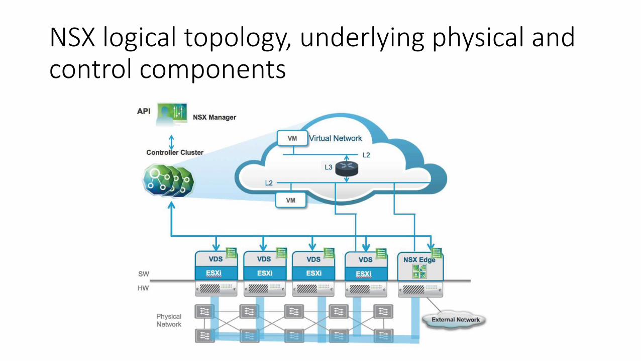
NSX logical topology, underlying physical and control components
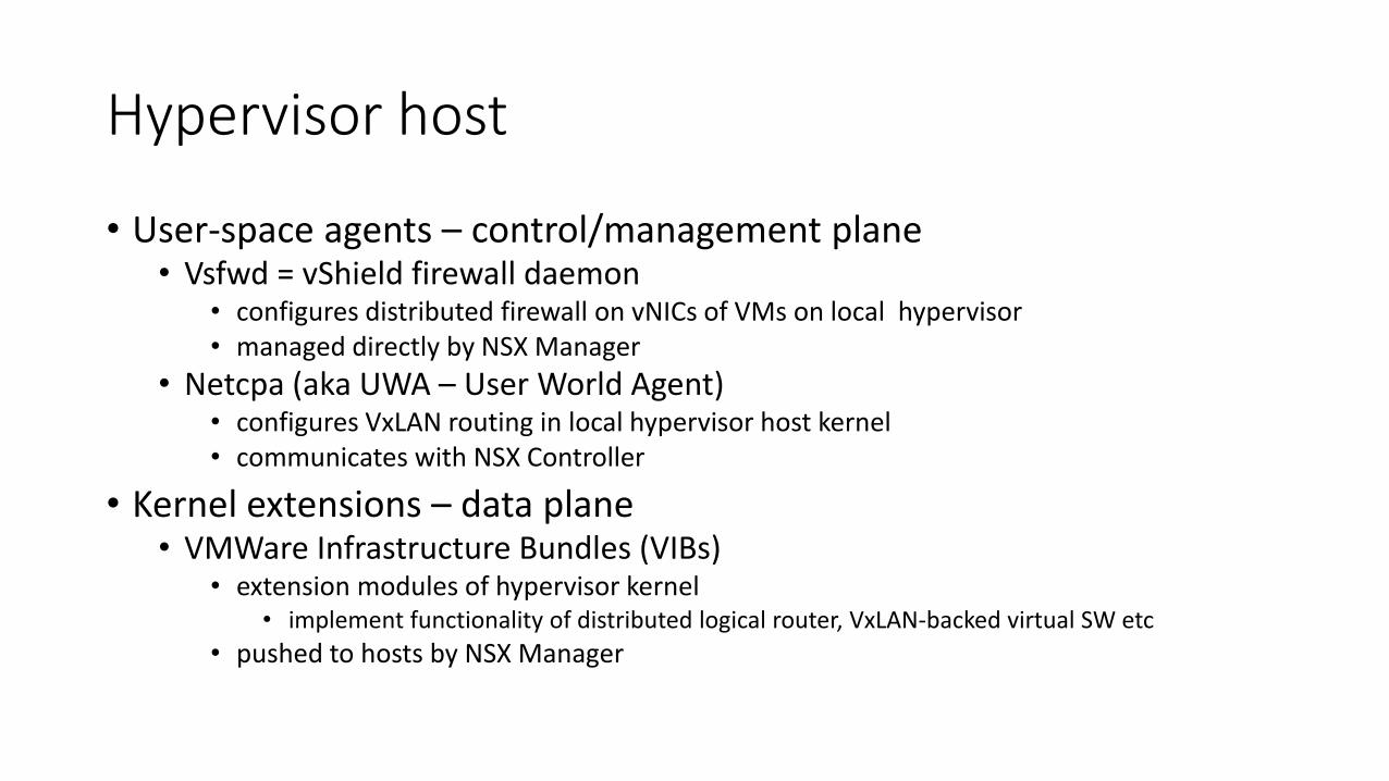
Hypervisor host
• User-space agents – control/management plane• Vsfwd = vShield firewall daemon
• configures distributed firewall on vNICs of VMs on local hypervisor• managed directly by NSX Manager
• Netcpa (aka UWA – User World Agent)• configures VxLAN routing in local hypervisor host kernel• communicates with NSX Controller
• Kernel extensions – data plane• VMWare Infrastructure Bundles (VIBs)
• extension modules of hypervisor kernel• implement functionality of distributed logical router, VxLAN-backed virtual SW etc
• pushed to hosts by NSX Manager
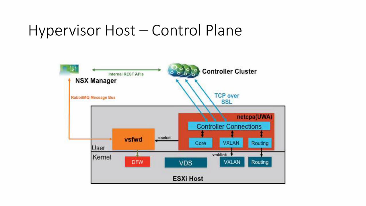
Hypervisor Host – Control Plane
NSX Controller Cluster• Always cluster of 3 nodes
• master is elected for each control role (Logical Switching, API Provider, Directory Server)• if only 1 controller survives, internal tables are considered read-only (i.e. no changes in the environment are learned, do not use VMotion in
this state)
• Slicing mechanism distributes workload between alive controller nodess (VNIs/VXLANs, …) • assignment of slices is controller by master
• Maintains and provides the following tables (per logical SW):• VTEP table – list of VTEPs for each VxLAN (VNI) - VNI+VTEP IP -> VTEP MAC• MAC table – VNI+MAC -> VTEP IP• ARP (suppression) table – VNI+IP->MAC
• Controller communicates with UWA agents in hypervisor hosts to control logical routing & switching• push all tables into individual hosts• DFW is handled by NSX Manager + vsfwd, NSX Controller not involved
• No need of multicast support in underlay network for unknown MACs• UWA of each hypervisor host reports MAC address + VNI of locally booted VMs to NSX Controller
• Hypervisor host kernel intercepts ARP requests and creates local response based on ARP table (cache) if an entry is present
• NSX Controller API is proprietary and not exposed to the user• NSX Manager API is the proper control point
• NSX Controller cluster (3 VMs) are deployed from OVF via NSX Manager
NSX Manager
• Separate management VM, paired with VCenter during installation
• Provides WWW GUI, Cisco-style CLI and REST API• CLI commands are read-only, GUI or API calls are needed for modifications
• Normally runs on management hypervisor cluster (with vCenter etc.)
NSX Manager CLI – Some useful commands
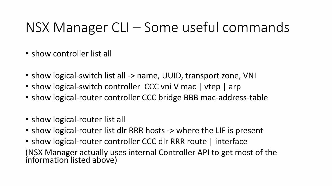
• show controller list all
• show logical-switch list all -> name, UUID, transport zone, VNI• show logical-switch controller CCC vni V mac | vtep | arp• show logical-router controller CCC bridge BBB mac-address-table
• show logical-router list all• show logical-router list dlr RRR hosts -> where the LIF is present• show logical-router controller CCC dlr RRR route | interface(NSX Manager actually uses internal Controller API to get most of the information listed above)
Logical SW
• Implemented using DVS and hypervisor kernel extension modules• can even span multiple DVSes
• set of hosts whose VMs can participates on the same user traffic L2 domain is defined by transport zone
• Uses VxLANs instead of VLANs• very similar to RFC VxLANs but uses NSX controller to learn MAC addresses.
• also uses non-RFC UDP destination port number
• Uses Virtual Tunnel Endpoint (VTEP) logical interface to encapsulate/decapsulateVxLAN traffic
• Each logical SW is associated with one VxLAN ID (VNI – VxLAN Network ID)• VNI pool normally starts from 5000
Transport Zone
• Logical vCenter construct
• List of hosts/clusters where each particular logical SW is present• each host may be part of multiple transport zones
• transport zone can cover multiple DVSes (i.e. carry the same VxLAN over multiple DVSes)
• Port Group created in vCenter will be created on all hosts in respective transport one
• Establishes boundary of (user) broadcast domains
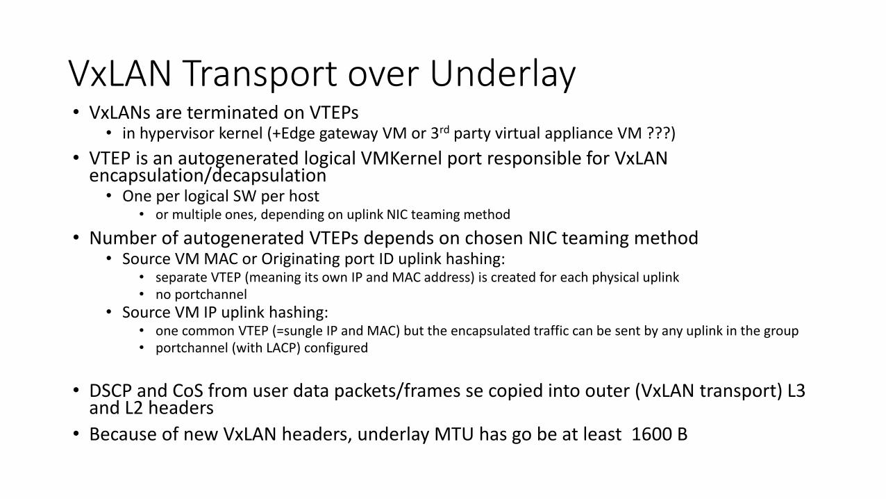
VxLAN Transport over Underlay• VxLANs are terminated on VTEPs
• in hypervisor kernel (+Edge gateway VM or 3rd party virtual appliance VM ???)
• VTEP is an autogenerated logical VMKernel port responsible for VxLANencapsulation/decapsulation• One per logical SW per host
• or multiple ones, depending on uplink NIC teaming method
• Number of autogenerated VTEPs depends on chosen NIC teaming method• Source VM MAC or Originating port ID uplink hashing:
• separate VTEP (meaning its own IP and MAC address) is created for each physical uplink• no portchannel
• Source VM IP uplink hashing:• one common VTEP (=sungle IP and MAC) but the encapsulated traffic can be sent by any uplink in the group• portchannel (with LACP) configured
• DSCP and CoS from user data packets/frames se copied into outer (VxLAN transport) L3 and L2 headers
• Because of new VxLAN headers, underlay MTU has go be at least 1600 B
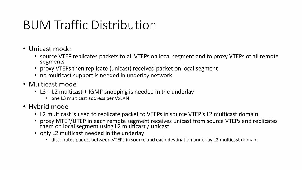
BUM Traffic Distribution
• Unicast mode• source VTEP replicates packets to all VTEPs on local segment and to proxy VTEPs of all remote
segments• proxy VTEPs then replicate (unicast) received packet on local segment• no multicast support is needed in underlay network
• Multicast mode• L3 + L2 multicast + IGMP snooping is needed in the underlay
• one L3 multicast address per VxLAN
• Hybrid mode• L2 multicast is used to replicate packet to VTEPs in source VTEP’s L2 multicast domain• proxy MTEP/UTEP in each remote segment receives unicast from source VTEPs and replicates
them on local segment using L2 multicast / unicast• only L2 multicast needed in the underlay
• distributes packet between VTEPs in source and each destination underlay L2 multicast domain
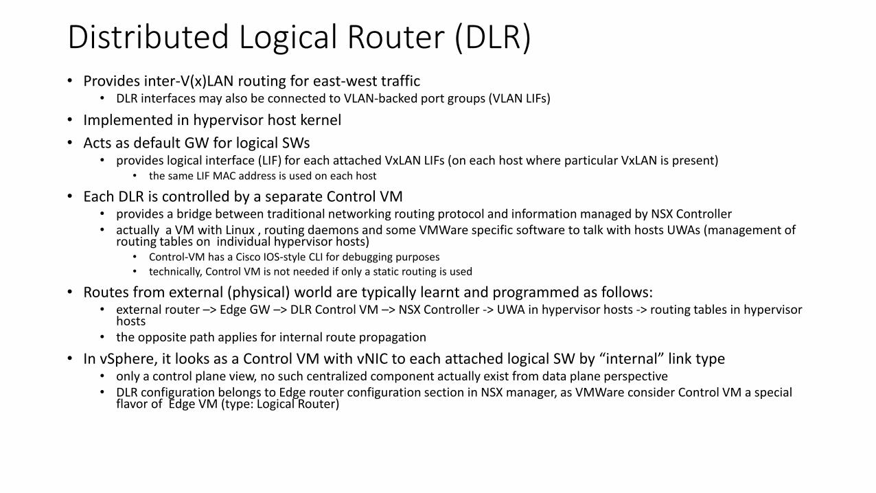
Distributed Logical Router (DLR)• Provides inter-V(x)LAN routing for east-west traffic
• DLR interfaces may also be connected to VLAN-backed port groups (VLAN LIFs)
• Implemented in hypervisor host kernel
• Acts as default GW for logical SWs• provides logical interface (LIF) for each attached VxLAN LIFs (on each host where particular VxLAN is present)
• the same LIF MAC address is used on each host
• Each DLR is controlled by a separate Control VM• provides a bridge between traditional networking routing protocol and information managed by NSX Controller• actually a VM with Linux , routing daemons and some VMWare specific software to talk with hosts UWAs (management of
routing tables on individual hypervisor hosts)• Control-VM has a Cisco IOS-style CLI for debugging purposes• technically, Control VM is not needed if only a static routing is used
• Routes from external (physical) world are typically learnt and programmed as follows:• external router –> Edge GW –> DLR Control VM –> NSX Controller -> UWA in hypervisor hosts -> routing tables in hypervisor
hosts• the opposite path applies for internal route propagation
• In vSphere, it looks as a Control VM with vNIC to each attached logical SW by “internal” link type• only a control plane view, no such centralized component actually exist from data plane perspective• DLR configuration belongs to Edge router configuration section in NSX manager, as VMWare consider Control VM a special
flavor of Edge VM (type: Logical Router)
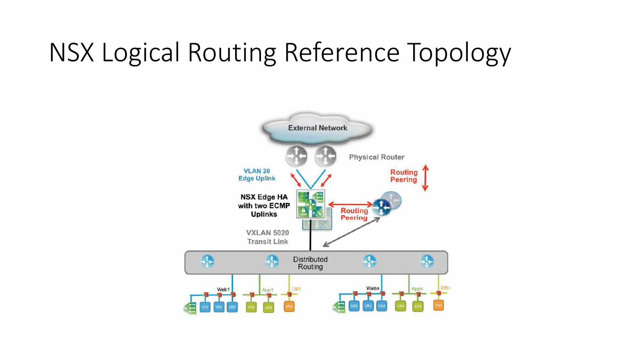
NSX Logical Routing Reference Topology

DLR – Logical and Physical View
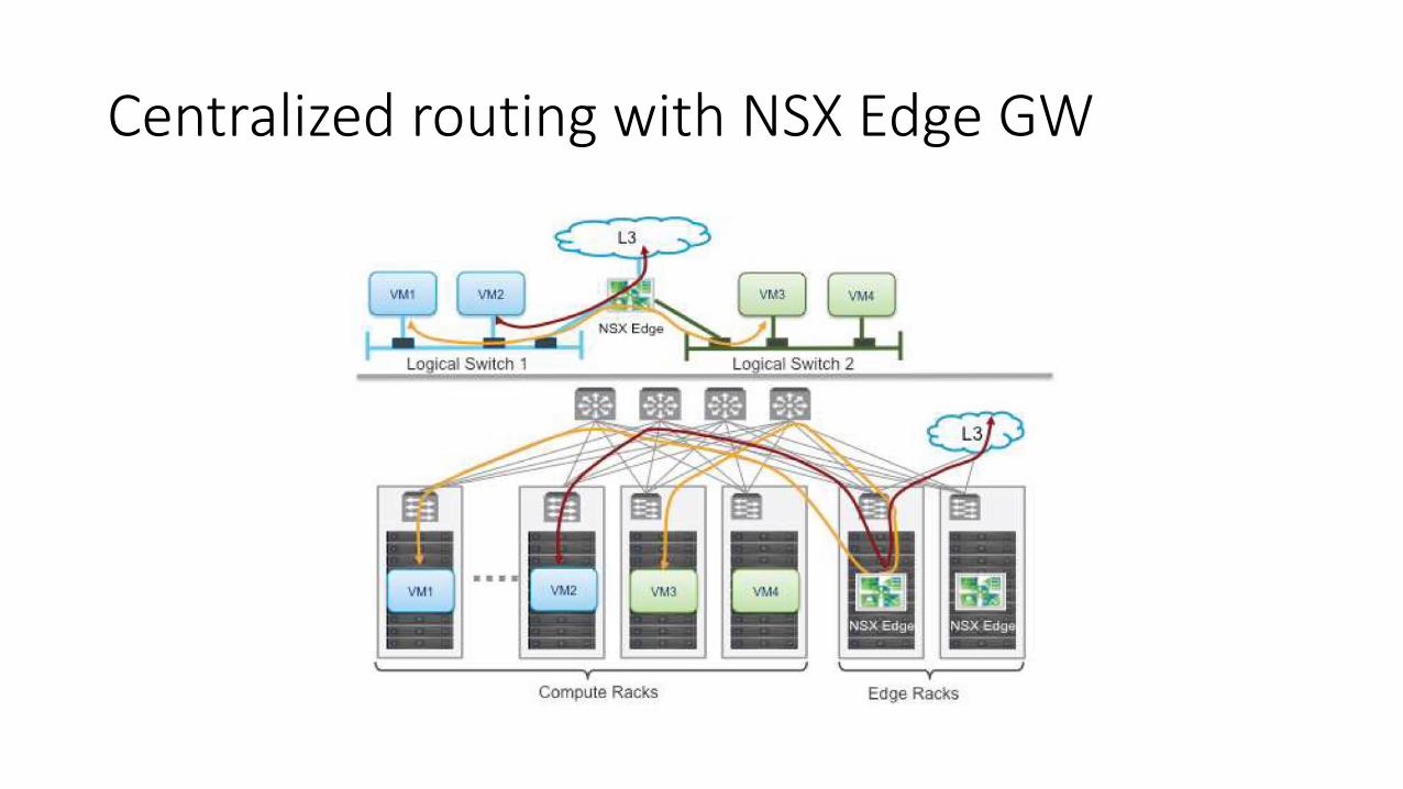
Centralized routing with NSX Edge GW

Optimized Horizontal Routing with DLR
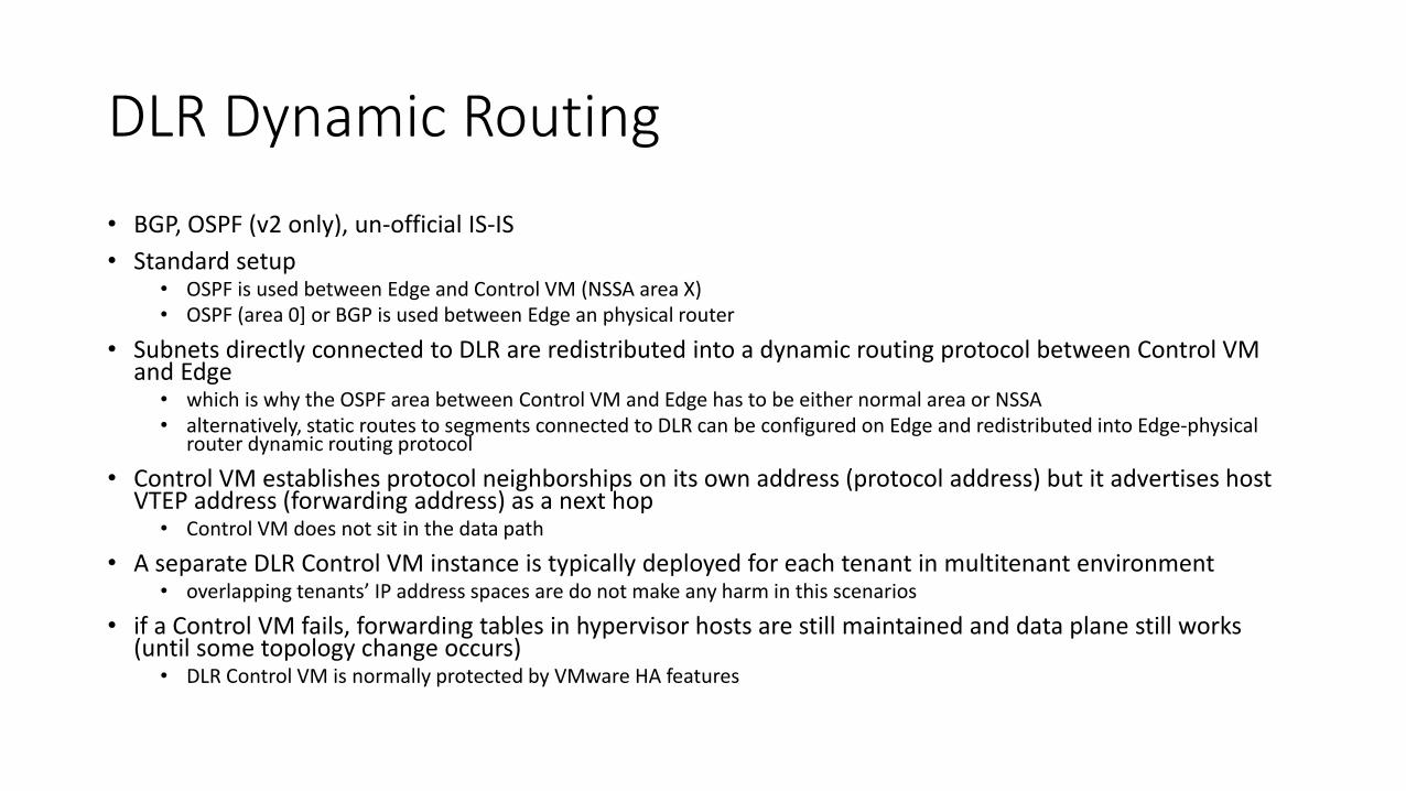
DLR Dynamic Routing
• BGP, OSPF (v2 only), un-official IS-IS
• Standard setup• OSPF is used between Edge and Control VM (NSSA area X)• OSPF (area 0] or BGP is used between Edge an physical router
• Subnets directly connected to DLR are redistributed into a dynamic routing protocol between Control VM and Edge
• which is why the OSPF area between Control VM and Edge has to be either normal area or NSSA• alternatively, static routes to segments connected to DLR can be configured on Edge and redistributed into Edge-physical
router dynamic routing protocol
• Control VM establishes protocol neighborships on its own address (protocol address) but it advertises host VTEP address (forwarding address) as a next hop
• Control VM does not sit in the data path
• A separate DLR Control VM instance is typically deployed for each tenant in multitenant environment• overlapping tenants’ IP address spaces are do not make any harm in this scenarios
• if a Control VM fails, forwarding tables in hypervisor hosts are still maintained and data plane still works (until some topology change occurs)
• DLR Control VM is normally protected by VMware HA features
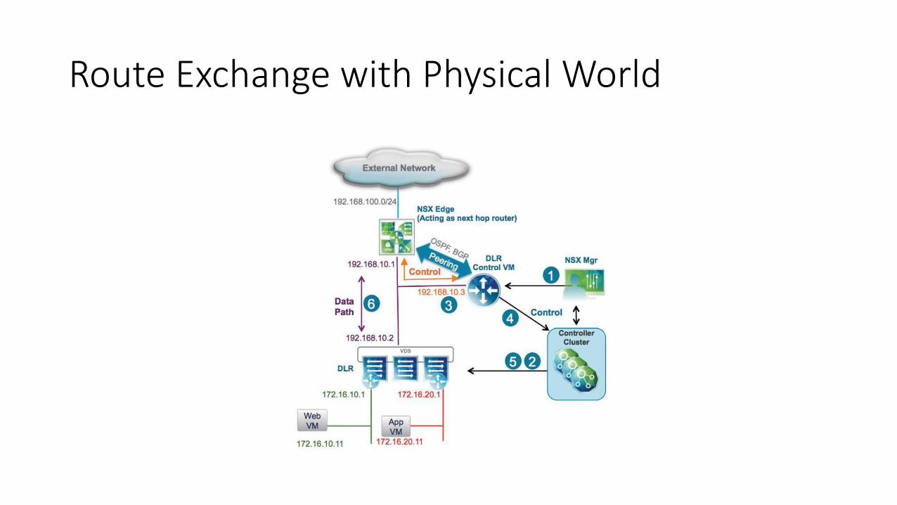
Route Exchange with Physical World
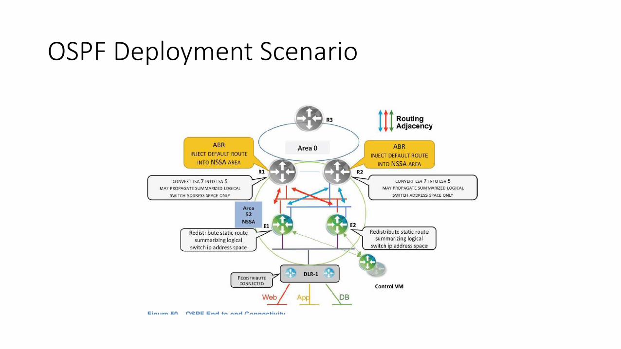
OSPF Deployment Scenario
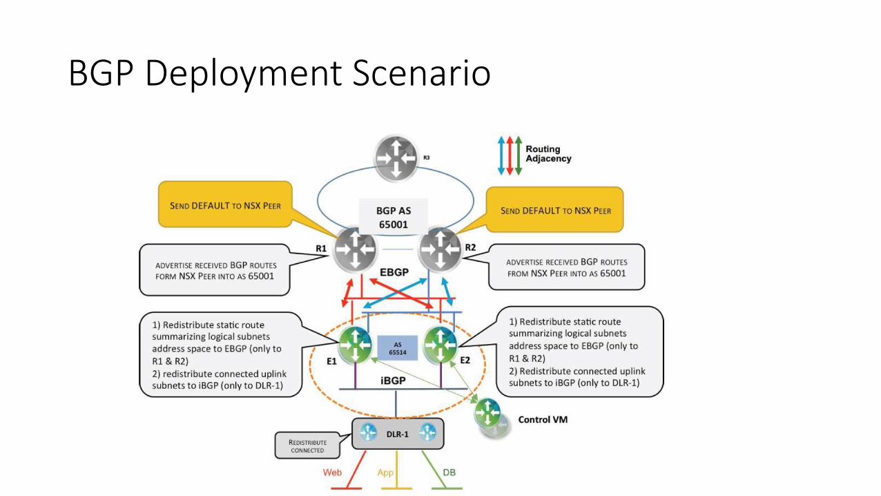
BGP Deployment Scenario
Distributed Firewall (DFW)
• FW rules enforced directly on user VM vNICs• support for microsegmentation – what is not explicitly allowed is denied even on the same networksegment
• inspects both incoming and outgoing traffic
• FW rules programmed directly into hypervisor kernel• advantage of distributed processing (realistic estimate 20 Gbps per host with negligible impact to CPU)
• per-vNIC copies of the rulebase are uploaded – scalability limit
• Stateful, utilizes traditional concept of flow table• 1st packet of the flow has to be always checked against FW rulebase. If it is permitted, a new flow table record is created
• subsequent packets of already permitted flow match flow table record and can be passed quickly without consulting FW rulebase
• NSX Manager programs FW rulebase directly to hypervisor hosts (vsfwd) - NSX Controller is not involved and in some use cases even not needed
• DFW may be extended with 3rd party (kernel) extensions• per-vNIC service insertion chains
• Only a single DFW instance exists, so all FW rules are configured on na single place• DFW rulebase is configured in NSX Manager: Networking & Security/Firewall section
• what we can do is to limit to which hosts/cluster each rule will be programmed to (target attribute)
• target attribute may specify that a DFW rule has to be installed to Edge GW also so that we do not need to keep the same rule on multiple places for 2 FWs in the chain
• Lot of source/destination criteria not applicable on traditional firewalls are available here• e.g. object Cluster mean “all user VMs currently present on particular host cluster”
• FW rules may also utilize information from Guest Introspection, i.e. internal info about user VM operating system status and configuration reported by VMWare tools
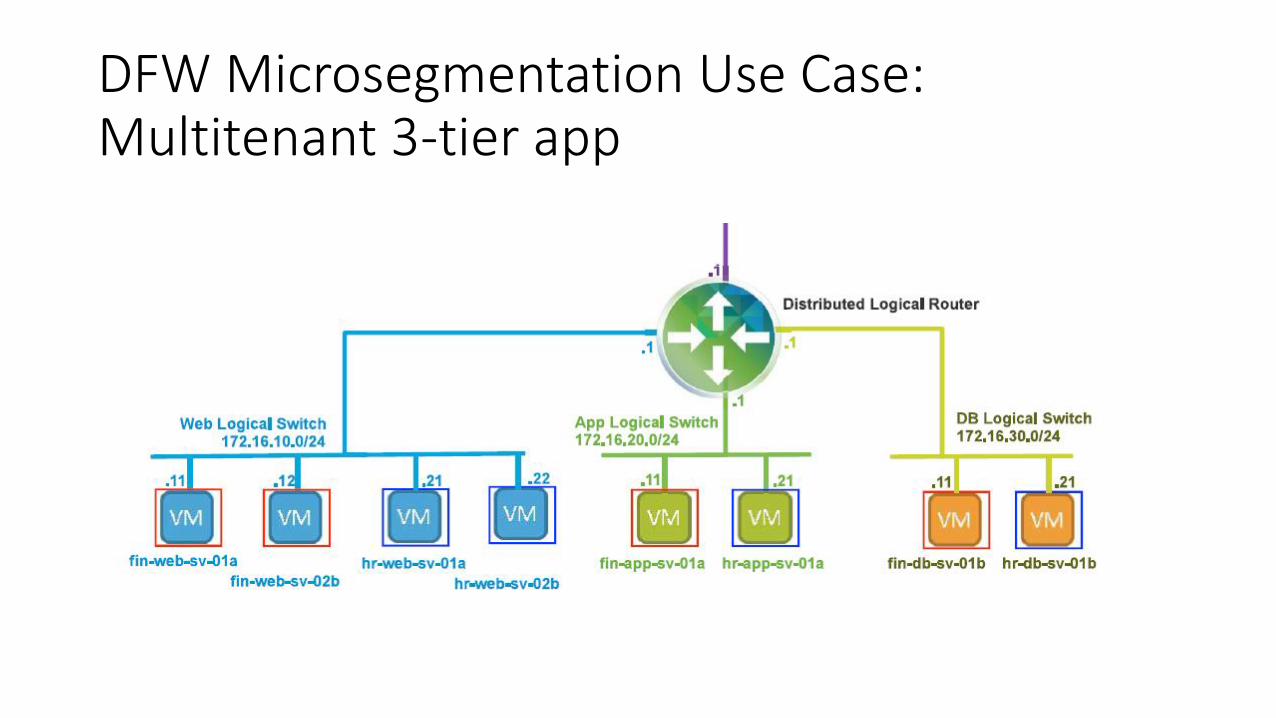
DFW Microsegmentation Use Case:Multitenant 3-tier app
NSX Edge Services Gateway
• Actually a Linux-based VM that sits between NSX logical topology and external world and provides a gateway between physical and NSX environment• various „form factors“ are available depending on expecte workload (differ in
number of vCPU and amount of memory)
• Provides south-north routing, firewaling, load balancing, SNAT/DNAT, VPN termination, DHCP + DNS relay (and DLR Control VM)• Support for OSPF, BGP and static routing
• Exposes Cisco-like CLI
• Multiple Edge GWs can be deployed (e.g. per tenant)
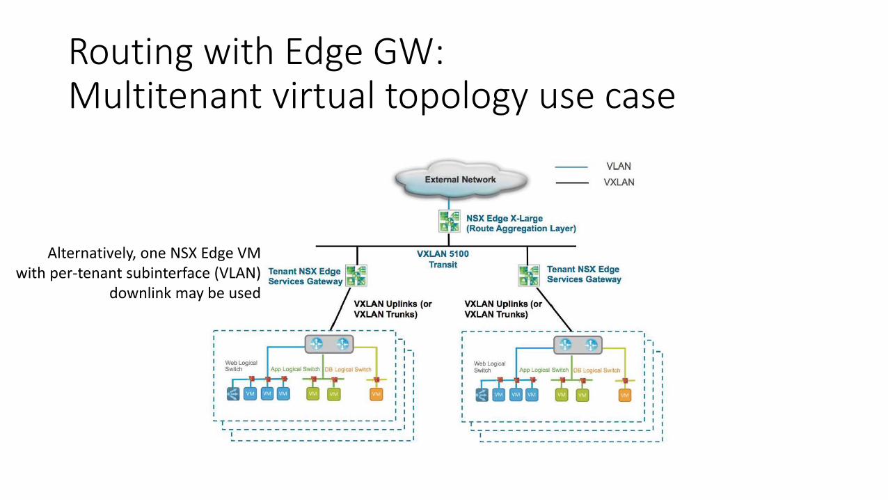
Routing with Edge GW:Multitenant virtual topology use case
Alternatively, one NSX Edge VM with per-tenant subinterface (VLAN)
downlink may be used
Edge VM High Availability
• vSphere HA or NSX Edge HA or their combination may be applied
• vSphere HA• In case of VM failure new VM is boote on another host using last status of image files stored on shared
storage visible from all hosts• service break for couple of minutes
• NSX Edge HA • utilizes active + standby Edge GW instance, preferably each on different storage• heartbeat detects active Edge GW failure (by default hello every 3s, failover after 5 missing hellos)• also synchronizes most of state information (FW, LB and NAT sessions), VPN connections currently NOT
synchronized• Only active Edge GW maintains dynamic routing peering sessions
• Active a standby GW use the same IP addresses but different MACs
• After failover, standby Edge GW sends gratitious ARP and takes over OSPF neighborships• OSPF dead timer should not be set too low as it must not expire during failover
• Combination of vSphere HA and NSX Edge HA is recommended• NSX Edge HA failover will be triggered first, then vSphere HA will activate a new Edge GW (keeping the original
one active to avoid another connectivity break)

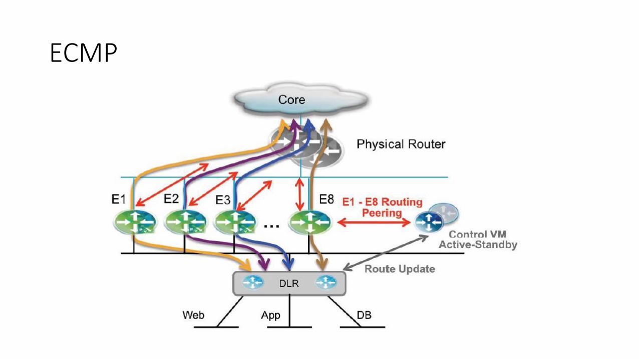
ECMP Routing via Multiple Edge GWs
• Equal-cost multipath routing between DLR and external physical router using alternative paths via up to 8 Edge GWs• routing adjacencies are established between DLR Control VM and each Edge GW
• failures of Edge GWs are detected using OSPF timers (3 sec is a minimum holdtime)
• Incompatible with stateful Edge GW features (FW, NAT) • no internal synchronization exist between Edge GW
• Edge GW VMs may utilize stateful VMWare HA to protect against host failure• anti-affinity rules should be configured to deny Distributed Resource Scheduler to
place all Edge GWs on the same host
ECMP
Edge Service Gateway Functions
VPN
• VPN tunnels terminated on Edge GW (currently no redundancy)
• L2 VPN• VxLAN/VLAN extension to anothere site (e.g. public cloud provider)• Frame transport over TCP/443• client-server model
• client side does not require full NSX installation, only Edge GW VM
• Edge GW has interfaces to internal logical SW and to Internet-facing port group• „trunk“ port with multiple subinterfaces (up to 200) for various internal VLAN/VxLAN may be also configured
• IPSec VPN• Local and remote subnets have to be defined, dynamic routing not supported• Only 3DES and AES128/256. Tunnel mode, ESP + IKEv1• Max 10 sites, 64 tunnels• 2Gbps throughput
• SSL VPN Plus• Intended for remote access• Full tunnel mode / split tunnel mode• Windows, Mac and Linux thick clients (alternatively launched from Web browser ?)• Data compression support
NAT
• Source NAT• 1:1
• PAT (masquerading)
• Destination NAT
Load Balancing
• Performs DNAT (+ SNAT in one-arm mode) for incoming sessions
• L7 mode nebo L4 mode
• One-arm (proxy) nebo Transparent (inline) mode• Inline mode cannot be used with DLR
• If SNAT in one-arm mode is an issue for client identity losss, x-forwarded-forHTTP header can be inserted to identify original source IP address
• Max 32 servers per pool, max 64 pools per Edge GW
• Server health checks on L4 / L7 (HTTP)
Edge Firewall
• Statefull• show flowtable command shows active flows
• May be deployed together with / without DFW• Edge FW is a NSX world’s perimeter FW for north/south traffic
• Rulebase configured via Networking & Security / Firewall (commonapproach with DFW configuration, target Edge GW needs to bespecified for particular rules)• Networking & Security / NSX Edge section was used for this in past
Service Composer
• Security model based on (static or dynamic) Security Groups which are referenced in Security Policies
• Security groups• dynamic grouping of user VMs according to various attributes
• statically included and statically excluded VMs {according to various attributes]
• static exclusions always wins
• security groups may be nested (hierarchical)
• VMs can be tagged with security tags• statically configured or or dynamically implied values
• security groups can be formed based on security tag values
• Security policies• specify FW rules and services to be implemented when communicating between security groups
• “Policy Security Group” may be used as source or destination specification in particular FW rule in security policy
• one security policy generally contain multiple FW rules (first-match search always apply)
• policy may inherit rules from another policies
• Security policies created in Service Composer and bound to Security Groups cause creation of FW rule visible in Networking & Security/Firewall section
• Service Composer is also a tool to configure service insertion • services of service chain inserted into slots of list associated with each vNIC of user VM
FW rules that are automatically created based on Service Composer model for particular VM are visible in VCenter VM view in “Monitor/ServiceComposer/FW rules” section. Current Security Group membership can be checked on the same place.
Additional Security Features
• Guest introspection• provides view into user VM OS/applications status• with OS agent or agentless• can dynamically tag VM with security tag based on intra-VM software state
• e.g. virus detection or indication of presence of sensitive data (PCI)• controlled from NSX Manager
• Network introspection• redirects inbound /outbound traffic for/from user VM via 3rd party virtual appliance
VM• IPS and other service 3rd party implementations
• In-guest FW• runs in guest OS (Windows/Linux)• Controlled from NSX Manager

L2 Bridging
• VxLAN to VLAN (VLAN-VLAN nor VxLAN-VxLAN not supported/needed)• Allows L2 communication between VM in VxLAN and VM in distributed port group or with a physical server behind DVS
uplink• Useful for migration scenarios and in situation where some server(s) cannot be virtualized (typically DB)
• Centralized solution – only a single bridging point is active to avoid bridging loop
• Formally implemented using DLR (see HA solution described below)• starting from NSX version 6.2, one DLR instance DLR can be used for routing and bridging simultaneously
• Implementation options:• HW VTEP• Software-based (implemented via DLR – in fact traffic passes just via host kernel module)
• 1) dedicated host for VLAN-VxLAN bridging (on the same host where DLR Control VM runs)• 2) one distributed SW, having both VTEP interface and VLAN portgroup on uplink trunk• VMWare kernel limitation: traffic bridged between VLAN and VxLAN must enter/exit on the same physical uplink porto Lze udělat v HA
módu
• High availability• 2 hosts may be used for bridging for redundancy, one holds DLR Control VM and another one acts as a standby for DLR
Control VM• real bridging always happen on host where DLR Control VM is currently active
Contrail
Contrail (1)
• OpenSource• optional commercial support from Juniper
• Multi-tenant host-based (/32) overlayed routing using MPLS over GRE• Similar to MPLS/VPN concept (host-based L3 routing)• Does not require MPLS underlay (any IP-based core fits)• Direct communication between compute nodes and with physical GW (with MPLS over GRE support)
• Solution components:• vRouters in Compute nodes
• Per-tenant VRFs
• Controller Node• Programs IP->VTEP mapping into virtual routers• act as kind of “BGP route reflector”
• maintains BGP sessions with edge GWs• pushes routing information to vRouters using XMPP
• Configuration Node• Physical edge routers with VRF and MPLS over GRE support• Analytics Engine Node
Contrail (2)
• Service insertion support
See also http://juniper.github.io/contrail-vnc/architecture.html
Current Hardware-based Overlay SDN Solutions• Cisco Application Centric Infrastructure (ACI)
Cisco Application Centric Infrastructure (ACI)
• Actually overlay termination and underlay transport on the same devices
• Leaf & Spine architecture + Controller cluster (Application Policy Infrastructure Controller – APIC)• Cisco Nexus switches with special OS image and special chipset (VxLAN encapsulation support, in HW, endpoint-to-VTEP mapping tables)
• Leaf switches provide encapsulation normalization and translation (VLAN/VxLAN/NVGRE -> internal VxLANs) to support multiple hypervisors and bare metal
• Spine switches provide ECMP transport for internal VxLANs and mapping between endpoint identity and current location (leaf VTEP)
• Centralized APIC-controlled control & management• automatic topology discovery/check
• administrator always uses controller (APIC) to configure network infrastructure and never touches physical boxes directly
• controller transforms configuration to per-device configuration commands and monitors physical devices’ operation
• Object-based model (tree) of networking constructs accessible via Controller API calls
• Attached hosts (VMs or physical on access ports or attached VLANs) are grouped together intp Endpoint Groups (EPG)• even using dynamic, attachment-port-independent criteria (e.g. VM name)
• Communication between members of EPGs have to be explicitly allowed using Contracts• everything else is implicitly denied
• communication logic (including firewalling service) of an application is completely described by a list of contracts between EPGs (without reference to any particular IP addresses etc) which is why the solution is called “application centric”
• infrastructure architect needs to know hosted application before deploying network infra for it (which may not be always true in practice...)
• Fully distributed L2 and L3 forwarding
• L2 or L3 communication with external world via physical ports of leaf switches• OSPF and BGP are supported
• Support for service insertion/chaining
• Support for analytics and telemetry

ACI Integration with Server virtualization Platform• APIC talk with (plugin of) respective Virtual Machine Manager (VMM)
• e.g. vCenter in VMWare case
• OpFlex protocol• Bidirectional communication
• ACI configures connection parameters for every VM
• VMM reports events like VM creation or move on particular hypervisor host
• lets ACI know current attachment point of particular MAC/IP address
• unique in scope of particular EPG, which may be most easily mapped to traditional VLAN connected to some port of ACI leaf switch
• Network connection of VMs can be visible/managed both from APIC GUI/CLI/API or VMM UI
ACI Service Chaining
• L2 (transparent) or L3 service instances• virtual or physical
• service chain that needs to be instantiated is described by service graph acting as an abstract “template”