Embed Size (px)
Citation preview
HAL Id: inria-00107795https://hal.inria.fr/inria-00107795
Submitted on 19 Oct 2006
HAL is a multi-disciplinary open accessarchive for the deposit and dissemination of sci-entific research documents, whether they are pub-lished or not. The documents may come fromteaching and research institutions in France orabroad, or from public or private research centers.
L’archive ouverte pluridisciplinaire HAL, estdestinée au dépôt et à la diffusion de documentsscientifiques de niveau recherche, publiés ou non,émanant des établissements d’enseignement et derecherche français ou étrangers, des laboratoirespublics ou privés.
Overlapping Multi-Processing and Graphics HardwareAcceleration: Performance Evaluation
Xavier Cavin, Laurent Alonso, Jean-Claude Paul
To cite this version:Xavier Cavin, Laurent Alonso, Jean-Claude Paul. Overlapping Multi-Processing and Graphics Hard-ware Acceleration: Performance Evaluation. Parallel Visualization and Graphics Symposium 1999,IEEE, 1999, San Francisco, CA, pp.79-88. �inria-00107795�
Overlapping Multi-Processing and Graphics Hardware Acceleration:Performance Evaluation
Xavier Cavin�
Laurent Alonso Jean-Claude Paul
LORIA�- INRIA Lorraine
Abstract
Recently, multi-processing has been shown to deliver good perfor-mance in rendering. However, in some applications, processorsspend too much time executing tasks that could be more efficientlydone through intensive use of new graphics hardware. We presentin this paper a novel solution combining multi-processing and ad-vanced graphics hardware, where graphics pipelines are used bothfor classical visualization tasks and to advantageously perform ge-ometric calculations while remaining computations are handled bymulti-processors. The experiment is based on an implementation ofa new parallel wavelet radiosity algorithm. The application is exe-cuted on the SGI Origin2000 connected to the SGI InfiniteReality2rendering pipeline. A performance evaluation is presented. Keep-ing in mind that the approach can benefit all available workstationsand super-computers, from small scale (2 processors and 1 graph-ics pipeline) to large scale (� processors and � graphics pipelines),we highlight some important bottlenecks that impede performance.However, our results show that this approach could be a promisingavenue for scientific and engineering simulation and visualizationapplications that need intensive geometric calculations.
CR Categories: I.3.1 [Computer Graphics]: HardwareArchitecture—Parallel processing ; I.3.1 [Computer Graphics]:Hardware Architecture—Graphics processors ; I.3.7 [ComputerGraphics]: Three-Dimensional Graphics and Realism—Radiosity
Keywords: Parallelism, Graphics Hardware, Hierarchical andMultiresolution Algorithm, Wavelet, Realistic Rendering, Radios-ity.
1 Introduction
1.1 Motivation
Recent commercial ccNUMA super-computers, like the SGI Ori-gin2000 [15], have been shown to perform and scale for a widerange of scientific and engineering applications [13]. It is impor-tant to evaluate their strengths and weaknesses for graphics render-ing applications. Recent papers have proven that parallelism makesit possible to deal with extremely large geometrical models in areasonable time within some rendering applications, such as realis-tic rendering [19, 20, 4, 18] or volume rendering [1]. On the otherhand, newly available graphics hardware now also provide high per-formance for rendering tasks. In some ways, since multi-processorsspeed up rendering computational times, they create the need forsoftware that replicates the functionalities of graphics hardware. Ina previous paper [4], we presented an efficient parallelization of awavelet radiosity algorithm and we pointed out this limitation ofparallelism for radiosity-based rendering.�615 rue du Jardin Botanique, BP 101, F-54602 Villers-les-Nancy
Cedex, France. [email protected]�LORIA is UMR 7503 LORIA, a joint research laboratory between
CNRS, Institut National Polytechnique de Lorraine, INRIA, UniversiteHenri Poincare and Universite Nancy 2.
1.2 Related work
Wavelet radiosity is a very efficient algorithm introduced by [12]and [22]. As with all hierarchical N-Body methods, this algorithmhas highly irregular and unpredictable data access patterns thatmake its parallelization challenging [25]. A few papers [11, 17, 5]have proposed a parallel implementation of hierarchical radiosityfor large models. Wavelet radiosity is also a hierarchical approach,but it provides a more formal mathematical framework for radios-ity. Thus, while dealing with high level order basis functions, itis able to compute highly precise radiosity solutions. It is impor-tant to point out that, in order to get this high precision, it mustperform much more interaction calculations between the finite ele-ments, compared to the classical hierarchical approach.
Despite this difficulty, we implemented a parallel radiosityalgorithm, based on linear wavelet bases, on the SGI Origin2000and obtained significant speed-ups. For instance, we ran ourapplication on the well-known Soda Hall building test model inorder to render a realistic walk-through. A radiosity solution with�����
patches (compared to the�� �������
initial surfaces) wascomputed in
���hours with
���processors, while it would take
about�
days on a single processor.
As previously pointed out, in our multi-processors environment,we had to use software-based computations that replicate the func-tionalities of available graphics hardware. Thus, we were curiousto evaluate how a sequential wavelet radiosity algorithm, benefit-ing from advanced capabilities of recent graphics hardware - likepbuffers - could perform.
In the radiosity literature, almost all implemented algorithmsrely on software. Nevertheless, one of the first implementationsof the radiosity method used a depth buffer to perform visibilityand form factors calculations between surfaces in the iterative ra-diosity solving process, either in a pre-processing step [7] or duringcomputations [6], and the authors suggested that dedicated graph-ics hardware could be devoted to this task. Recently, two papershave also proposed using graphics hardware in realistic radiosity[14, 16], but the use of hardware is devoted to the ultimate render-ing pass, not to the kernel evaluation of the radiative process.
In [2], we proposed acceleration techniques, taking advantageof existing graphics hardware, to speed-up the visibility queries.These techniques are already advantageously integrated inside oursequential wavelet radiosity algorithm. For the purpose of thepresent paper, we have tested this sequential program on a SGIOnyx machine connected to the SGI RealityEngine2 and renderedthe Soda Hall model in about
�� hours. These results are similar to
those that would be obtained on the SGI Origin2000 with 8 pro-cessors. In other words, comparable speed-ups have been obtainedwith a sequential implementation taking advantage of graphicshardware acceleration, than with a parallel implementation wherea lot of time is spent performing intensive geometric calculations.
The new algorithm presented in this paper has been designedto take advantage of both multi-processing and graphics hardwareacceleration. In the radiosity rendering process, graphics hardware
is commonly used, similarly to other visualization applications, atthe final visualization step. We obviously do this also. The keydifference is that we also use graphics hardware for acceleratingsome costly computational tasks - the visibility queries - during theradiosity equation solving process.
We must note that this idea has been previously introduced in[3]. In this paper, the authors have proposed a method that en-hances radiosity algorithm performance by using the capabilities ofa multi-processors graphics workstation: hemicube items are pro-duced by a master processor using the graphics hardware, as in [7],while the remaining computations are performed in parallel on theremaining processors. Our algorithm differs from this solution inthree ways:� our wavelet radiosity algorithm more efficiently performs
highly precise solutions than the classical algorithm proposed;� using a clever visibility algorithm, our implementation doesnot suffer from all the drawbacks of the standard Z-bufferhardware;� we do not use a master-slave scheme, thus allowing our par-allel implementation to scale and deal with various combina-tions of processors and graphics pipelines.
However, the approach we propose is very similar in spirit.
1.3 Aims and organization of the paper
In summary, the advantages of our new algorithm are:� our novel wavelet radiosity algorithm is of complexity������
[21], it can deal with high order basis functions and renderextremely large models;� our parallel implementation allows both acceptable load bal-ancing and excellent data locality, that permits the scaling ofthe wavelet algorithm to a large number (
� ) of processors;� the graphics hardware computes the visibility calculations re-
quired by the wavelet radiosity solver between � and��
timesfaster than a software package and moreover, frees the multi-processors for other computational tasks.
The novel algorithm was implemented on the SGI Origin2000,which is a ccNUMA super-computer, with MIPS R10000 proces-sors and an aggressive, scalable distributed shared memory (DSM)architecture. This machine was configured for the experiment witha single SGI InfiniteReality2.
To validate our approach, the new algorithm has been tested onthe classroom reference test scene, made available by Peter Shirleyfor the
���Eurographics Workshop on Rendering. Using this
model, we measured the performance of our new scheme. We alsohighlight the most important bottlenecks that come in the way ofperformance, keeping in mind that our new scheme could benefitall available graphics workstations, from small scale ( � processorsand
�graphics pipeline) to large scale (� processors and � graphics
pipelines). Finally, we tested our algorithm on the Soda Hall model.
In Section 2, we briefly recall general concepts on wavelet ra-diosity and show how its structure offers some insight to partition-ing the algorithm across multiprocessors and graphics hardware.Section 3 shows how we advantageously use parallelism to performthis algorithm, while Section 4 presents how graphics hardware ac-celeration could be successfully applied in a sequential implemen-tation. Then, in Section 5, we show how overlapping multiprocess-ing and graphics hardware acceleration can enhance parallel real-istic rendering. Performance evaluation and results are presentedand discussed in Section 6 and a general discussion is exposed inSection 7. Finally, Section 8 concludes and presents future work.
2 Wavelet Radiosity Algorithm Structure
Let us first recall, for the sake of clarity, the radiosity equation, andmore specifically the terms involved in it and their implication tothe parallelization process.
The radiosity - power per unit area [ � ����� ] - on a given surfaceis defined as the light energy leaving the surface per unit area. Let�
denote the collection of all surfaces in an environment, and �be a space of real-valued functions defined on
�����; that is, over
all surface points and all wavelengths (�
). Our goal is to determinethe surface radiosity function ����� that satisfies:
� ����� � �"!$# �����%� �'&)( �����*� � +-,). �/�10/� � �*� �����2�10 �43 �10��(1)
where�
is the wavelength at which functions are computed.
2.1 The wavelet radiosity solver
The�
, # and ( terms
These three terms represent the input data of a radiosity simulationproblem:� �
consists of the set of input surfaces. They can be eithersimple triangles or polygons, or more complex shapes;� # �����%� � specifies the origin and directional distribution ofemitted light. It either represents point light sources or self-emitting surfaces from
�;� ( �����%� � is the local reflectance function of the surface. Within
the radiosity assumption, we suppose that the surfaces are ide-ally diffuse (i.e. lambertian surfaces).
The�
, and to a lesser extent, # and ( terms are responsible forthe irregular characteristic of the physical domain being simulated.The initial distribution of surfaces and emitted energy make it dif-ficult to anticipate how and where the computational power will befocused: distributing it in parallel will be even more challenging.
The � term
The � �����%� � term is the radiosity function we aim to compute. Inorder to make it calculable, � must be projected in a finite dimen-sion subspace. Let �456�6� be a subspace of � of dimension �and 798':%; :=<?>A@*B C C C B 5�D one of its bases, we now have to determine the79E4:%; :=<?>A@*B C C C B 5�D coefficients, so that:
�GFH��5�! 5I :KJ"@ E : 8 :%LThe choice of the basis functions is very important, because it
greatly influences both the the precision of the approximated func-tion and the complexity of the computations. Historically, the firstradiosity algorithms used piecewise constant functions. For effi-ciency reasons, more recent algorithms have introduced hierarchi-cal and wavelet [12, 23] functions.
Using hierarchical wavelet bases, however, gives to the algo-rithm a dynamic and unpredictable characteristic. Indeed, inputsurfaces of
�are subdivided as the computation proceeds, making
it impossible to foresee both the time needed to compute an en-ergy transfer and the total amount of memory required (i.e. mem-ory must be dynamically allocated). Obviously, this becomes evenmore problematic in parallel.
The �,
integral
The integral equation codes the interactions between all surfacepoints of the input scene. The resolution process solving this equa-tion is closely related to the different terms of Equation 1 and usesthem to make the needed computations.
The resolution can be tackled using two main approaches, calledgathering and shooting. The two approaches are based on GaussSeidel and Southwell iterative methods, which are very well de-scribed in [8] or [24]. In the first one, each step in an iterationupdates the coefficient of one basis function, by accumulating theenergy of all others basis functions. A total iteration consists ofthe set of necessary steps to update all basis functions. The conver-gence rate can be accelerated by the shooting algorithm, allowingit to draw intermediate results quickly. Each step updates all ba-sis functions coefficients by propagating the basis function with themost energy. The convergence is faster, but the computation errorsare propagated along with the resolution.
The two approaches exhibit common problems concerning theirparallelization. First, care must be taken when accessing and up-dating data structures in parallel. Then, the work of propagatingenergy between basis functions has to be distributed among pro-cesses in a well load-balanced way. Finally, data accesses must bedone efficiently in order to get good data locality.
2.2 The � term. �/� 0 �*� � is a geometry term defined by:. �/�10/� � �"!�������� ��������� � � � � � �/�10=�*� � �where � is the length of the vector connecting the two surface points�
and� 0
, and � and �� � are the angles between the local surfacenormals and this vector (see Figure 1).
x
x’
θx’xθrx’xn
x
nx’
Figure 1: Components of geometry term
..
The right part of the
.term is the visibility function � �/� 0 �*� � ,
that gives it a global scope. Indeed, the visibility function mayinvolve any other surface, not just the two interacting ones. Thisfunction is responsible for most of the discontinuities in the finalsolution � , and so shall be as exact as possible, with respect tothe precision of � . Visibility accuracy has a cost and may beresponsible for the largest part of the overall computation time,especially in the wavelet radiosity algorithm.
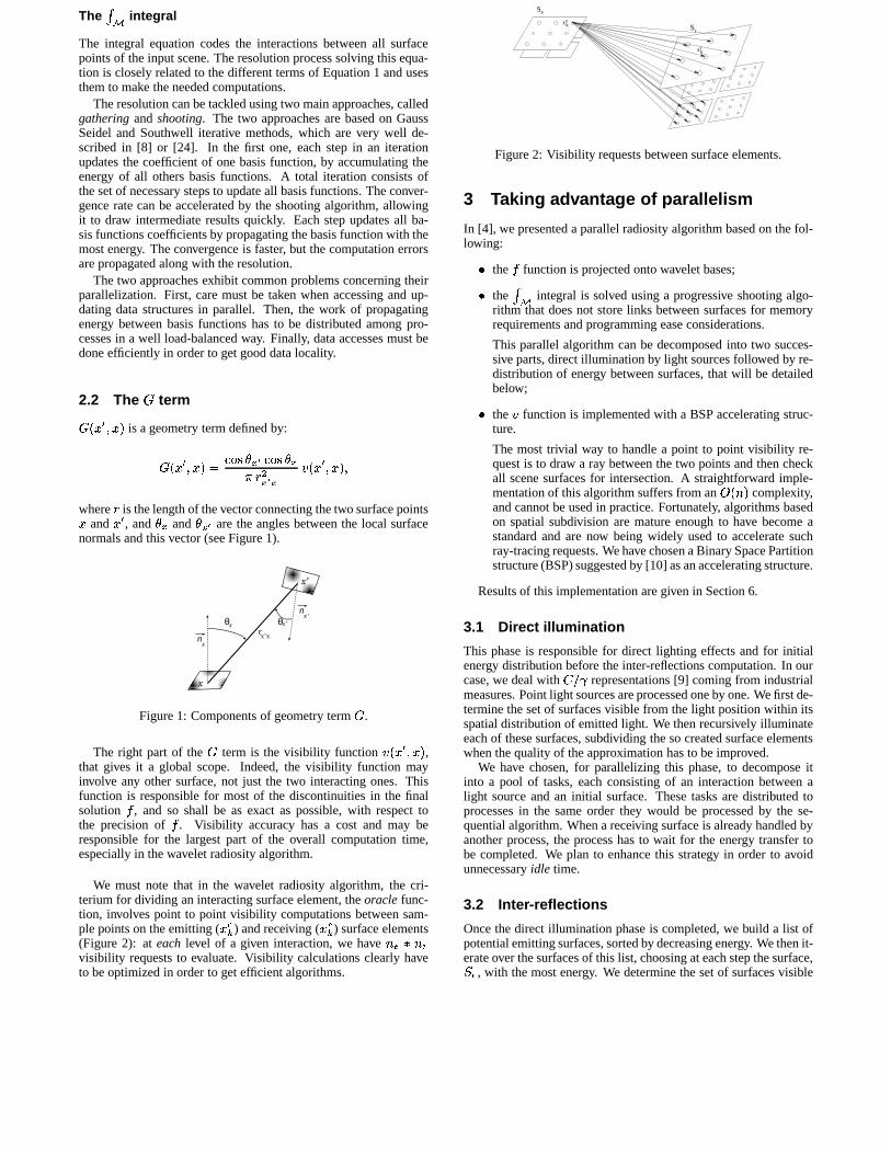
We must note that in the wavelet radiosity algorithm, the cri-terium for dividing an interacting surface element, the oracle func-tion, involves point to point visibility computations between sam-ple points on the emitting (
����) and receiving (
����) surface elements
(Figure 2): at each level of a given interaction, we have � ��� � �visibility requests to evaluate. Visibility calculations clearly haveto be optimized in order to get efficient algorithms.
eS
x e k
rS
k rx
Figure 2: Visibility requests between surface elements.
3 Taking advantage of parallelism
In [4], we presented a parallel radiosity algorithm based on the fol-lowing:� the � function is projected onto wavelet bases;� the �
,integral is solved using a progressive shooting algo-
rithm that does not store links between surfaces for memoryrequirements and programming ease considerations.
This parallel algorithm can be decomposed into two succes-sive parts, direct illumination by light sources followed by re-distribution of energy between surfaces, that will be detailedbelow;� the � function is implemented with a BSP accelerating struc-ture.
The most trivial way to handle a point to point visibility re-quest is to draw a ray between the two points and then checkall scene surfaces for intersection. A straightforward imple-mentation of this algorithm suffers from an
���� � complexity,
and cannot be used in practice. Fortunately, algorithms basedon spatial subdivision are mature enough to have become astandard and are now being widely used to accelerate suchray-tracing requests. We have chosen a Binary Space Partitionstructure (BSP) suggested by [10] as an accelerating structure.
Results of this implementation are given in Section 6.
3.1 Direct illumination
This phase is responsible for direct lighting effects and for initialenergy distribution before the inter-reflections computation. In ourcase, we deal with � ��� representations [9] coming from industrialmeasures. Point light sources are processed one by one. We first de-termine the set of surfaces visible from the light position within itsspatial distribution of emitted light. We then recursively illuminateeach of these surfaces, subdividing the so created surface elementswhen the quality of the approximation has to be improved.
We have chosen, for parallelizing this phase, to decompose itinto a pool of tasks, each consisting of an interaction between alight source and an initial surface. These tasks are distributed toprocesses in the same order they would be processed by the se-quential algorithm. When a receiving surface is already handled byanother process, the process has to wait for the energy transfer tobe completed. We plan to enhance this strategy in order to avoidunnecessary idle time.
3.2 Inter-reflections
Once the direct illumination phase is completed, we build a list ofpotential emitting surfaces, sorted by decreasing energy. We then it-erate over the surfaces of this list, choosing at each step the surface,� � , with the most energy. We determine the set of surfaces visible
from� � and for each surface,
� � , in it, we recursively propagatethe energy, as was done in the direct illumination phase, except thatnow, both surfaces can be subdivided into surface elements (Fig-ure 2). Once the energy transfer is computed, the updated receivingsurface,
� � , is inserted into the sorted list.This phase has been parallelized in two ways, one using the inner
loop of the sequential algorithm, that is for a given emitting surface,� � , the loop over the receiving surfaces,� � , and the other using
the outer loop, that is the loop over emitting surfaces,� � . Both
approaches have their drawbacks (synchronization barriers for thefirst one, restrictive access to the receiving surface and lower con-vergence rate for the second one), but can be advantageously com-bined to minimize their drawbacks: time consuming most energeticsurfaces can be handled with the inner loop parallelization at the be-ginning of the resolution, while the final interactions can be quicklycomputed by the outer loop parallelization until convergence.
4 Taking advantage of graphics hardware
The radiosity algorithms presented in Section 3 contain two mainkinds of visibility requests:� point to environment or surface to environment requests, i.e.
what surfaces are potentially visible, from a point or a sur-face? These requests consist of ”clipping” the subset of inputsurfaces visible from the current emitter;� point to point requests, i.e. is a point visible from anotherpoint?
Our implementation of the BSP-based visibility algorithm pre-sented in Section 3 can only answer point to point requests. Thus,all scene surfaces are potential receivers for a given emitter andmust be checked for visibility. Even despite the spatial accelerat-ing structure, all these visibility queries are still responsible for toohuge a part of the computation time.
Another solution to speed up visibility computations is to turn to-ward projective approaches. This can be achieved by using the newadvances in both graphics workstation architectures and graphics li-braries, that allow programmers direct and fast access to the resultsof graphics boards computations, such as the Z-buffer algorithm.
Let us see how visibility requests can be efficiently answered us-ing this approach, and how this impacts on the computation times,and consequently on the previously achieved parallel speed-up. Amore detailed presentation of hardware-based visibility algorithmscan be found in [2]. Results of this implementation are given inSection 6.
4.1 Hardware visibility
This method is inspired from the hemicube method, originally de-voted to computing form factors in classical radiosity.
The original hemicube method starts by associating each inputsurface with a unique color1, keeping one for the background. Itthen builds a hemicube of
�pixmaps centered over the point of
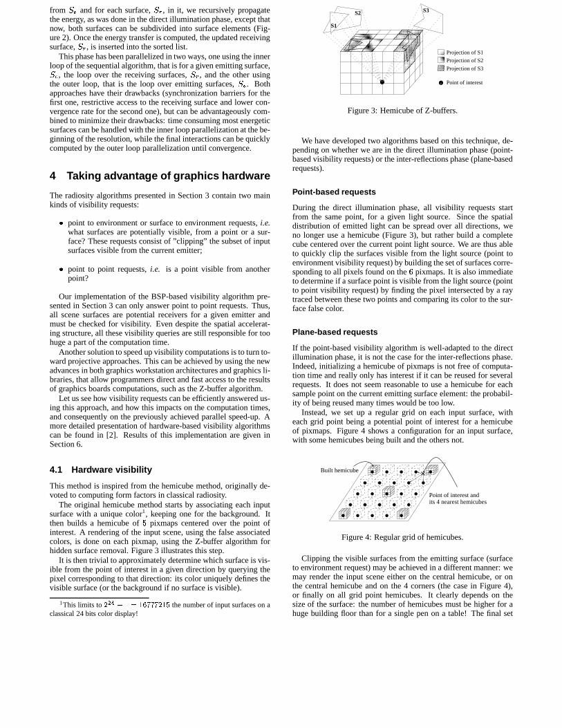
interest. A rendering of the input scene, using the false associatedcolors, is done on each pixmap, using the Z-buffer algorithm forhidden surface removal. Figure 3 illustrates this step.
It is then trivial to approximately determine which surface is vis-ible from the point of interest in a given direction by querying thepixel corresponding to that direction: its color uniquely defines thevisible surface (or the background if no surface is visible).
1This limits to � � ����������� � � � �� the number of input surfaces on aclassical 24 bits color display!
Projection of S1
Projection of S2
Projection of S3
S2 S3
S1
Point of interest
Figure 3: Hemicube of Z-buffers.
We have developed two algorithms based on this technique, de-pending on whether we are in the direct illumination phase (point-based visibility requests) or the inter-reflections phase (plane-basedrequests).
Point-based requests
During the direct illumination phase, all visibility requests startfrom the same point, for a given light source. Since the spatialdistribution of emitted light can be spread over all directions, weno longer use a hemicube (Figure 3), but rather build a completecube centered over the current point light source. We are thus ableto quickly clip the surfaces visible from the light source (point toenvironment visibility request) by building the set of surfaces corre-sponding to all pixels found on the
�pixmaps. It is also immediate
to determine if a surface point is visible from the light source (pointto point visibility request) by finding the pixel intersected by a raytraced between these two points and comparing its color to the sur-face false color.
Plane-based requests
If the point-based visibility algorithm is well-adapted to the directillumination phase, it is not the case for the inter-reflections phase.Indeed, initializing a hemicube of pixmaps is not free of computa-tion time and really only has interest if it can be reused for severalrequests. It does not seem reasonable to use a hemicube for eachsample point on the current emitting surface element: the probabil-ity of being reused many times would be too low.
Instead, we set up a regular grid on each input surface, witheach grid point being a potential point of interest for a hemicubeof pixmaps. Figure 4 shows a configuration for an input surface,with some hemicubes being built and the others not.
Built hemicube
Point of interest andits 4 nearest hemicubes
Figure 4: Regular grid of hemicubes.
Clipping the visible surfaces from the emitting surface (surfaceto environment request) may be achieved in a different manner: wemay render the input scene either on the central hemicube, or onthe central hemicube and on the 4 corners (the case in Figure 4),or finally on all grid point hemicubes. It clearly depends on thesize of the surface: the number of hemicubes must be higher for ahuge building floor than for a single pen on a table! The final set
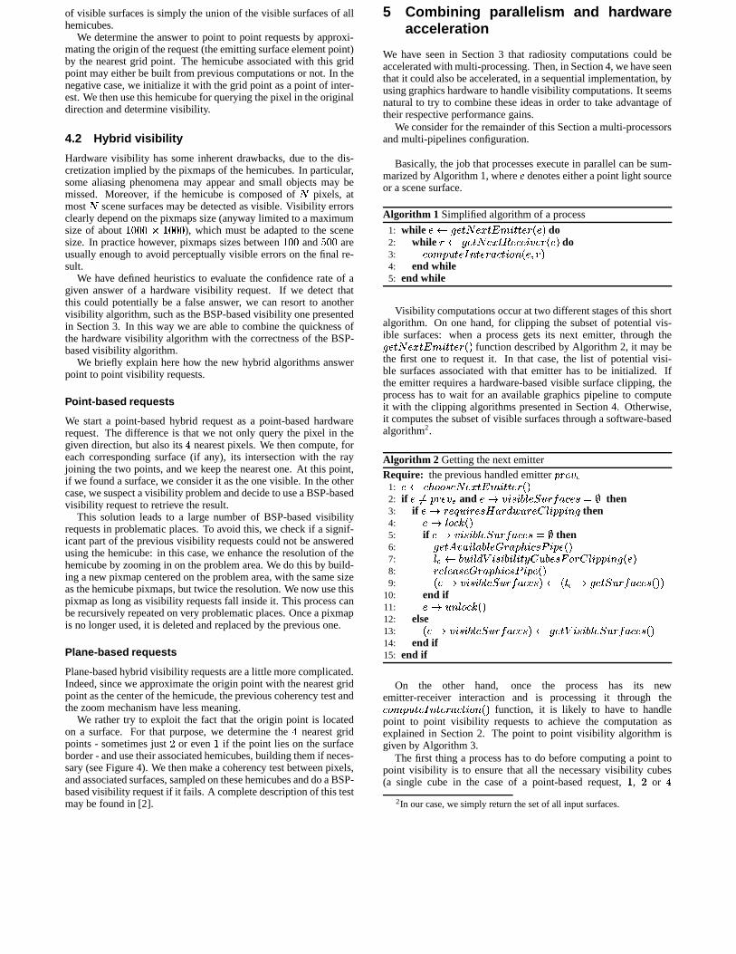
of visible surfaces is simply the union of the visible surfaces of allhemicubes.
We determine the answer to point to point requests by approxi-mating the origin of the request (the emitting surface element point)by the nearest grid point. The hemicube associated with this gridpoint may either be built from previous computations or not. In thenegative case, we initialize it with the grid point as a point of inter-est. We then use this hemicube for querying the pixel in the originaldirection and determine visibility.
4.2 Hybrid visibility
Hardware visibility has some inherent drawbacks, due to the dis-cretization implied by the pixmaps of the hemicubes. In particular,some aliasing phenomena may appear and small objects may bemissed. Moreover, if the hemicube is composed of � pixels, atmost � scene surfaces may be detected as visible. Visibility errorsclearly depend on the pixmaps size (anyway limited to a maximumsize of about
��� � ���), which must be adapted to the scene
size. In practice however, pixmaps sizes between��
and�
areusually enough to avoid perceptually visible errors on the final re-sult.
We have defined heuristics to evaluate the confidence rate of agiven answer of a hardware visibility request. If we detect thatthis could potentially be a false answer, we can resort to anothervisibility algorithm, such as the BSP-based visibility one presentedin Section 3. In this way we are able to combine the quickness ofthe hardware visibility algorithm with the correctness of the BSP-based visibility algorithm.
We briefly explain here how the new hybrid algorithms answerpoint to point visibility requests.
Point-based requests
We start a point-based hybrid request as a point-based hardwarerequest. The difference is that we not only query the pixel in thegiven direction, but also its
nearest pixels. We then compute, for
each corresponding surface (if any), its intersection with the rayjoining the two points, and we keep the nearest one. At this point,if we found a surface, we consider it as the one visible. In the othercase, we suspect a visibility problem and decide to use a BSP-basedvisibility request to retrieve the result.
This solution leads to a large number of BSP-based visibilityrequests in problematic places. To avoid this, we check if a signif-icant part of the previous visibility requests could not be answeredusing the hemicube: in this case, we enhance the resolution of thehemicube by zooming in on the problem area. We do this by build-ing a new pixmap centered on the problem area, with the same sizeas the hemicube pixmaps, but twice the resolution. We now use thispixmap as long as visibility requests fall inside it. This process canbe recursively repeated on very problematic places. Once a pixmapis no longer used, it is deleted and replaced by the previous one.
Plane-based requests
Plane-based hybrid visibility requests are a little more complicated.Indeed, since we approximate the origin point with the nearest gridpoint as the center of the hemicude, the previous coherency test andthe zoom mechanism have less meaning.
We rather try to exploit the fact that the origin point is locatedon a surface. For that purpose, we determine the
nearest grid
points - sometimes just � or even�
if the point lies on the surfaceborder - and use their associated hemicubes, building them if neces-sary (see Figure 4). We then make a coherency test between pixels,and associated surfaces, sampled on these hemicubes and do a BSP-based visibility request if it fails. A complete description of this testmay be found in [2].
5 Combining parallelism and hardwareacceleration
We have seen in Section 3 that radiosity computations could beaccelerated with multi-processing. Then, in Section 4, we have seenthat it could also be accelerated, in a sequential implementation, byusing graphics hardware to handle visibility computations. It seemsnatural to try to combine these ideas in order to take advantage oftheir respective performance gains.
We consider for the remainder of this Section a multi-processorsand multi-pipelines configuration.
Basically, the job that processes execute in parallel can be sum-marized by Algorithm 1, where � denotes either a point light sourceor a scene surface.
Algorithm 1 Simplified algorithm of a process
1: while ��� #�������� � ���� �����9� � ��� do2: while ��� #�������� � ��������� � �9� � ��� do3: ����� ��������� ����� ����� � !�� � � � ���4: end while5: end while
Visibility computations occur at two different stages of this shortalgorithm. On one hand, for clipping the subset of potential vis-ible surfaces: when a process gets its next emitter, through the#�������� � ���� �����9� � � function described by Algorithm 2, it may bethe first one to request it. In that case, the list of potential visi-ble surfaces associated with that emitter has to be initialized. Ifthe emitter requires a hardware-based visible surface clipping, theprocess has to wait for an available graphics pipeline to computeit with the clipping algorithms presented in Section 4. Otherwise,it computes the subset of visible surfaces through a software-basedalgorithm2.
Algorithm 2 Getting the next emitterRequire: the previous handled emitter �-�"� � �
1: �#�$��%&���('��)��� � �*�+ ������ � � �2: if �-,! �-�"� � � and ��. � /'� !0�12� � �1� �&������' !43 then3: if ��. ���)5��� =����'�6�� ��387�� ������19 ���� �'# then4: �#.:1;���A( � �5: if ��. � /'� <0�12� � �1���&������' !43 then6: #�����= � �� <1;��0�1;� . ��� ��%& !��'�>� ��� � �7: 19?@�:0��& /1K3�A* /'� !0� <1; ��B �#��0���'�C���� ��19 ���� �'# � ���8: �"�)12����'�� . ��� ��%& !��')>� ��� � �9:
� �#. � /'� !0�12� � �-���&������'9�D� � 1E?F. #���� � �-���&������' � �*�10: end if11: ��.:� �G1;���A( � �12: else13:
� ��. � /'� <0�12� � �1���&������'9�D� #�����A� /'� !0�12� � �1� �&������' � �14: end if15: end if
On the other hand, once the process has its newemitter-receiver interaction and is processing it through the����� �&�&����� ����� ����� � !��� � � function, it is likely to have to handlepoint to point visibility requests to achieve the computation asexplained in Section 2. The point to point visibility algorithm isgiven by Algorithm 3.
The first thing a process has to do before computing a point topoint visibility is to ensure that all the necessary visibility cubes(a single cube in the case of a point-based request,
�, � or
2In our case, we simply return the set of all input surfaces.
Algorithm 3 Computing a point to point visibility requestRequire: two points ��� � and �&� �
1: 19?F� #���� A� /'� !0 /19 !��B �#��0���' � �&� � �2: if
� � 19?@. ����� ��� ���� � �*� then3: #����= � �� <1;��0�12� . ��� ��%& !��'�>� ��� � �4: for each � � 19? do5: if
� � � .$����� ��� �8�� � �*� then6: � . 1;���A( � �7: if
� � � .$����� ��� �8�� � �*� then8: � . 0 �� <1 3 � �9: � . '������ ��� ��� �8��� � �
10: end if11: � .:� � 19��� ( � �12: end if13: end for14: �"�)12����'�� . ��� ��%& !��')>� ��� � �15: end if16: ����� ��������A� �'� !0� <1; ���B �
��� � � 1E? � �&� � �hemicubes for a plane-based request) have been built. If not, it hasto wait for an available graphics pipeline in order to build them oneby one. It is important to note that the process keeps the graphicspipeline until all visibility cubes are completed. Once all thesevisibility cubes are up to date, the visibility computation can bedone.
The key point in these algorithms is obviously the#�����= � �� <1;��0�12� . ��� ��%& !��')>� ��� � � function that makes the pro-cess that calls it wait for a graphics pipeline to be free in order tomake the desired operations on it. In addition to the two calls madein Algorithms 2 and 3, this function can also be called from insidea hybrid point-based visibility request which decided to enhanceits pixmap resolution over a problematic place.
In an ideal world where each process would have its own graph-ics pipeline, this would not be problematic. However, in commonconfigurations, the number of available graphics pipelines is lowerthan the number of processors. Thus, graphics pipelines becomecritical resources that must be shared between processes. In theworst cases, say for instance
�graphics pipeline for
�� processors,
processes will come to spend their time waiting for the critical re-sources instead of doing worthwhile computations, thus losing thebenefits of hardware acceleration.
We have felt the need to enhance the previous algorithms inorder to handle these problematic, but common, situations. Theidea is very simple: instead of waiting for an available graphicspipeline until it is acquired, the #����= � �� <1;��0�12� . ��� ��%& !��'�>� ��� � �function makes a fixed number of attempts3 to get one and returnsan error code if it fails. In those cases, we may either retry toget a graphics pipeline or resort to a software-based solution: the#���� A� /'� <0�12� � �1���&������' � � function in Algorithm 2 or a BSP-basedvisibility request in the two other cases. A further enhancementcould be to attribute the graphics pipelines in priority to Algo-rithm 2 in order to favor surface clipping operations.
6 Results
6.1 Experimental environment
Technical constraints
All the presented algorithms have been implemented inside theCANDELA platform, a research project designed to provide both aflexible architecture for testing and implementing new radiosity and
3In our current implementation, we use��
attempts.
radiance algorithms [26], and to handle real input data (complexgeometrical surfaces, accurate light sources models, real spectrummodeling) in order to compute physically correct results.
The CANDELA software consists of approximatively ��
C++classes and is based on the Open Inventor library. This enablesus to obtain the required flexibility, both on inputs and algorith-mic combinations. Parallelizing C++ algorithms inside such a largeplatform can seem challenging. It will be important not to deviatetoo far from the sequential code in order that we can still make validcomparisons and take advantage of the code’s latest enhancements.
Hardware
The experiments were run on a SGI Origin2000 with 64 processorsorganized in 32 nodes. Each node consists of two � ���� proces-sors with 32 K-Bytes of first level cache (L1) of data on the chip,4 M-Bytes of external second level cache (L2) of data and instruc-tions and 256 M-Bytes of local memory, for a total of 8 G-Bytesof physical memory. It was connected to a SGI InfiniteReality2graphics pipeline with one raster manager.
Measures
The � ���� hardware performance counters combined with thesoftware tool perfex allow performance measures of the behaviorof the parallel program. This allows us to study, among others:� Speed-up. This is defined by the ratio of the best sequential
time over the parallel time obtained with � processors.� Memory overhead. This is the ratio of time spent in memoryover the total execution time.� L1 cache hit rate. This is the fraction of data accesses whichare satisfied from a cache line already resident in the primarydata cache.� L2 cache hit rate. This is the fraction of data accesses whichare satisfied from a cache line already resident in the sec-ondary data cache.
Moreover, we have instrumented the CANDELA libraries in orderto monitor locks and synchronization times and to get informationabout the application behavior, in terms of handled surfaces or vis-ibility requests.
6.2 Performance evaluation
For the purpose of performance evaluation, we have performed sev-eral experiments on a single test scene: the classroom model pro-vided by Peter Shirley. This scene consists of
� ����initial surfaces
and
light sources. We have chosen to consider:� the hybrid hardware-based visibility algorithm,
– with visible surfaces clipping either enabled or dis-abled,
– with different pixmaps sizes: �
,��
, � � ;� the BSP-based visibility algorithm for comparison;� �to� � processors;� a convergence rate4 of about
��;� the inner loop parallel shooting algorithm: at each step the
most energetic surface is shot by all processes, with a syn-chronization barrier at the end.
4Computed as � � �� ����������������������� ������ �!������"#�#��$%������ ����.
(a) BSP. (b) Hardware. (c) Hybrid.
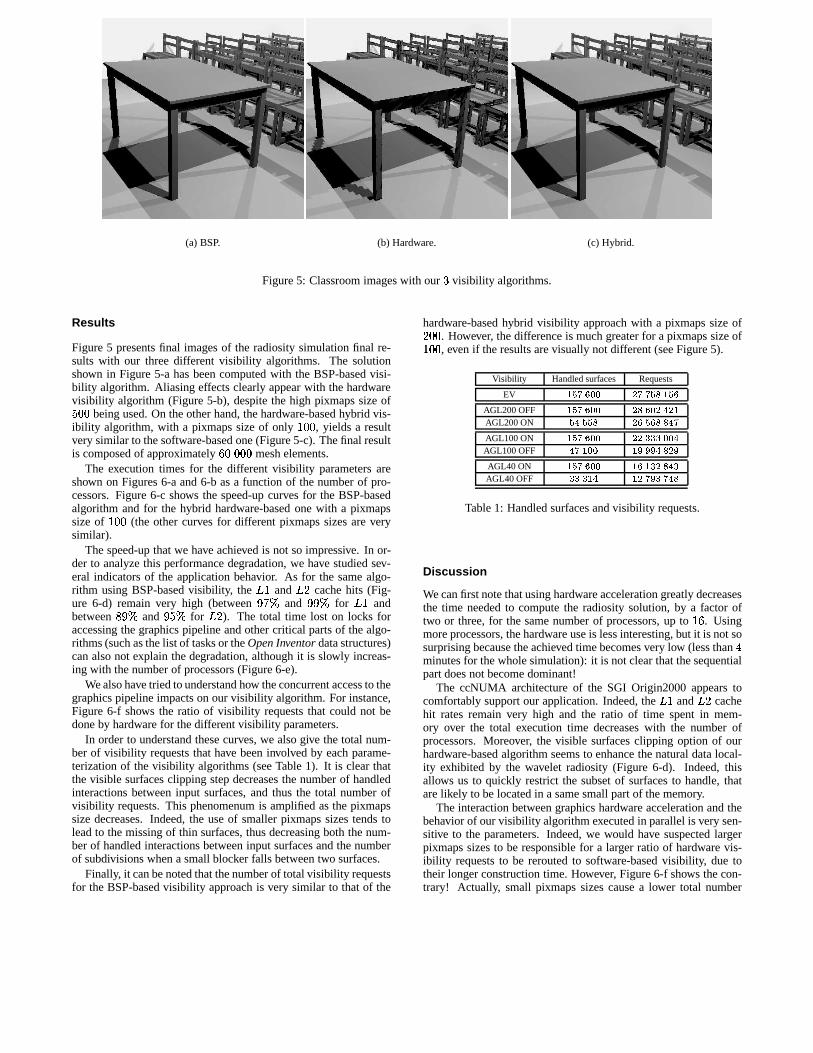
Figure 5: Classroom images with our�
visibility algorithms.
Results
Figure 5 presents final images of the radiosity simulation final re-sults with our three different visibility algorithms. The solutionshown in Figure 5-a has been computed with the BSP-based visi-bility algorithm. Aliasing effects clearly appear with the hardwarevisibility algorithm (Figure 5-b), despite the high pixmaps size of�
being used. On the other hand, the hardware-based hybrid vis-ibility algorithm, with a pixmaps size of only
��, yields a result
very similar to the software-based one (Figure 5-c). The final resultis composed of approximately
���mesh elements.
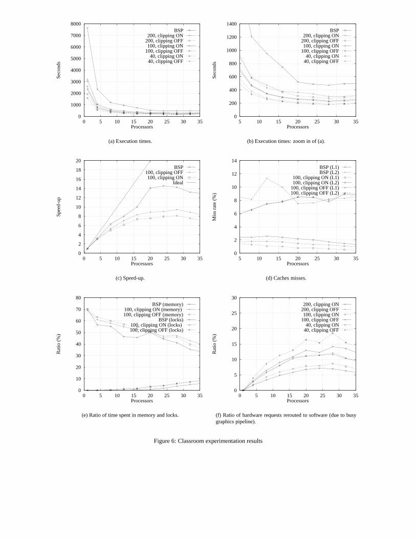
The execution times for the different visibility parameters areshown on Figures 6-a and 6-b as a function of the number of pro-cessors. Figure 6-c shows the speed-up curves for the BSP-basedalgorithm and for the hybrid hardware-based one with a pixmapssize of
���(the other curves for different pixmaps sizes are very
similar).The speed-up that we have achieved is not so impressive. In or-
der to analyze this performance degradation, we have studied sev-eral indicators of the application behavior. As for the same algo-rithm using BSP-based visibility, the � � and � � cache hits (Fig-ure 6-d) remain very high (between
����and
����for � � and
between � �� and����
for � � ). The total time lost on locks foraccessing the graphics pipeline and other critical parts of the algo-rithms (such as the list of tasks or the Open Inventor data structures)can also not explain the degradation, although it is slowly increas-ing with the number of processors (Figure 6-e).
We also have tried to understand how the concurrent access to thegraphics pipeline impacts on our visibility algorithm. For instance,Figure 6-f shows the ratio of visibility requests that could not bedone by hardware for the different visibility parameters.
In order to understand these curves, we also give the total num-ber of visibility requests that have been involved by each parame-terization of the visibility algorithms (see Table 1). It is clear thatthe visible surfaces clipping step decreases the number of handledinteractions between input surfaces, and thus the total number ofvisibility requests. This phenomenum is amplified as the pixmapssize decreases. Indeed, the use of smaller pixmaps sizes tends tolead to the missing of thin surfaces, thus decreasing both the num-ber of handled interactions between input surfaces and the numberof subdivisions when a small blocker falls between two surfaces.
Finally, it can be noted that the number of total visibility requestsfor the BSP-based visibility approach is very similar to that of the
hardware-based hybrid visibility approach with a pixmaps size of� . However, the difference is much greater for a pixmaps size of��, even if the results are visually not different (see Figure 5).
Visibility Handled surfaces Requests
EV ������� ������� �����AGL200 OFF ������ �� ����������AGL200 ON ������ �������� � ���AGL100 ON ������ ������������AGL100 OFF ������� ��������� ���AGL40 ON ������ ���������� ���AGL40 OFF ��������� �������������
Table 1: Handled surfaces and visibility requests.
Discussion
We can first note that using hardware acceleration greatly decreasesthe time needed to compute the radiosity solution, by a factor oftwo or three, for the same number of processors, up to
���. Using
more processors, the hardware use is less interesting, but it is not sosurprising because the achieved time becomes very low (less than
minutes for the whole simulation): it is not clear that the sequentialpart does not become dominant!
The ccNUMA architecture of the SGI Origin2000 appears tocomfortably support our application. Indeed, the � � and � � cachehit rates remain very high and the ratio of time spent in mem-ory over the total execution time decreases with the number ofprocessors. Moreover, the visible surfaces clipping option of ourhardware-based algorithm seems to enhance the natural data local-ity exhibited by the wavelet radiosity (Figure 6-d). Indeed, thisallows us to quickly restrict the subset of surfaces to handle, thatare likely to be located in a same small part of the memory.
The interaction between graphics hardware acceleration and thebehavior of our visibility algorithm executed in parallel is very sen-sitive to the parameters. Indeed, we would have suspected largerpixmaps sizes to be responsible for a larger ratio of hardware vis-ibility requests to be rerouted to software-based visibility, due totheir longer construction time. However, Figure 6-f shows the con-trary! Actually, small pixmaps sizes cause a lower total number
0
1000
2000
3000
4000
5000
6000
7000
8000
0 5 10 15 20 25 30 35
Seco
nds
Processors
BSP200, clipping ON
200, clipping OFF100, clipping ON
100, clipping OFF40, clipping ON
40, clipping OFF
(a) Execution times.
0
200
400
600
800
1000
1200
1400
5 10 15 20 25 30 35
Seco
nds
Processors
BSP200, clipping ON
200, clipping OFF100, clipping ON
100, clipping OFF40, clipping ON
40, clipping OFF
(b) Execution times: zoom in of (a).
0
2
4
6
8
10
12
14
16
18
20
0 5 10 15 20 25 30 35
Spee
d-up
Processors
BSP100, clipping OFF100, clipping ON
Ideal
(c) Speed-up.
0
2
4
6
8
10
12
14
5 10 15 20 25 30 35
Mis
s ra
te (
%)
Processors
BSP (L1)BSP (L2)
100, clipping ON (L1)100, clipping ON (L2)
100, clipping OFF (L1)100, clipping OFF (L2)
(d) Caches misses.
0
10
20
30
40
50
60
70
80
0 5 10 15 20 25 30 35
Rat
io (
%)
Processors
BSP (memory)100, clipping ON (memory) 100, clipping OFF (memory)
BSP (locks)100, clipping ON (locks) 100, clipping OFF (locks)
(e) Ratio of time spent in memory and locks.
0
5
10
15
20
25
30
0 5 10 15 20 25 30 35
Rat
io (
%)
Processors
200, clipping ON200, clipping OFF100, clipping ON
100, clipping OFF40, clipping ON
40, clipping OFF
(f) Ratio of hardware requests rerouted to software (due to busygraphics pipeline).
Figure 6: Classroom experimentation results
of visibility requests. Thus, the time needed to build the pixmapsbecomes important compared to the visibility computations time,and a larger proportion of hardware visibility requests are blocked.Large pixmaps sizes lead to a large number of visibility requests,and thus to a better reuse of already build pixmaps.
The granularity we used for the parallelization is surely the mostproblematic aspect of this experimentation. Indeed, the inner loopparallelization has two drawbacks: first, the preparation (i.e. thepush/pull of the energy at each level) of the surface with the mostenergy that will be handled in parallel has to be done sequentially.Second, a synchronization barrier is needed before the next surfaceto be handled. The time lost at these two points, as the number ofprocessors increase, may be largely responsible for the performancedegradation.
7 General discussion
Graphics hardware acceleration greatly increases the efficiency ofour wavelet radiosity algorithm, and even more so when combinedwith multi-processing. Indeed, the high computational resourcesrequired by wavelet radiosity are mainly devoted to visibility re-quests which can be efficiently solved by hardware using dedicatedgraphics pipelines. Moreover, our hardware-based visibility algo-rithms greatly benefit from the spatial coherency of the involvedvisibility requests, thus allowing a large reuse of structures builtwith hardware.
An efficient hardware acceleration, however, can only beachieved if the application has direct access to the results of thecomputations made by the graphics pipelines. Recent advances ingraphics architectures now allow such a direct connection5: on theSGI systems, this is done through a pixel buffer (pbuffer for short).If no direct connection is available, it is certainly better to turn to-ward a software-based solution!
Combined use of graphics hardware and multi-processing intro-duce a new bottleneck in algorithms relying on this scheme. Indeed,a given graphics pipeline cannot be accessed in parallel by severalprocesses. During our tuning phase, we have noticed that waitingfor the graphics pipeline to be free can be very time-consuming.In those cases, it is better, when possible, to resort to an equivalentsoftware-based algorithm. When tasks of differing importance haveto be performed by hardware, it could also be interesting to intro-duce a priority system. In our case, clipping visible surfaces mustbe done in priority before other visibility computations, becauseother processes may be waiting for the result of this computation.Of course, using a multi-pipelines configuration, these access con-flicts will be reduced. In an ideal world, we could have one pipelinefor one processor! Our experiments seem to show that one pipelinefor
or � processors could be sufficient.
Finally, in order to fully benefit from the graphics hardwareacceleration, the load-balancing of our parallel radiosity algorithmhas to be improved in order to avoid unnecessary idle time (whenwaiting for a surface to be free) and synchronization barriers.Indeed, these phenomena are mainly responsible for our badspeed-up curves, which are still not really convincing.
Despite the early state of our work on this new promising com-bination, we were able to compute a radiosity solution of the SodaHall building within
� �minutes for the direct illumination of the� � point light sources and about � hours for both the
���emitting
surfaces and��
shooting iterations, on���
processors and a sin-gle graphics pipeline. Figure 7 and 8 show images of the obtainedresult.
5Actually, you may have to decrease the screen resolution in order to geta pbuffer visual for ��� computations.
8 Conclusion and future work
We have presented in this paper a new parallel wavelet algorithmthat uses a novel combination of multi-processors and graphicshardware. The solution proposed consists of using the capabil-ities of graphics hardware for performing the costly geometriccalculations, while the remaining computations are performed inparallel on the processors. Executing this program on the SGIOrigin2000 with
� � processors and the SGI InfiniteReality2, wecompute a highly precise radiosity solution in a near reasonabletime. Moreover, our algorithm also benefits from the graphicspipeline for rendering interactive visualization at every step of theiterative resolution process. In a multi-processors/multi-pipelinesenvironment, some processors could have a read-only access to thecomputation results in progress and have their own pipeline(s) forinteractively displaying intermediate results. As a result, we thinkthat our new scheme is a promising avenue to make 3D realisticrendering from geometric models tractable, at last, for real worldapplications. We also think that the combination that we proposecould be used in some other applications. Physical simulation,such as heat transfer, acoustic simulation, N-body methods, etc,may also benefit from the combined multi-resolution approach andgraphics hardware acceleration.
More performance evaluations are needed for tailoring ourscheme to work well at different scales. Our goal in future ex-periments is to extend our approach from small scale ( � processorsand
�graphics pipeline) to large scale (� processors and � graphics
pipelines) systems.
Acknowledgments
We would like to thank the Centre Charles Hermite for providingthe resources necessary to the experimentations implied by our re-search work, and especially Alain Filbois for the time spent on thegraphics system configuration, the members of the ISA team fortheir work on the CANDELA project and Carlo Sequin who pro-vided the Soda Hall model.
References
[1] James Ahrens and James Painter. Efficient Sort-Last Render-ing Using Compression-Based Image Compositing. In Pro-ceedings of the Second Eurographics Workshop on ParallelGraphics and Visualisation, pages 145–154, Rennes, France,September 1998. Eurographics.
[2] Laurent Alonso and Nicolas Holzschuch. Using graph-ics hardware to speed-up your visibility queries. Journalof Graphics Tools, 1999. Submitted for publication. Alsoavailable as http://www.loria.fr/˜holzschu/Publications/99-R-030.pdf.
[3] Daniel R. Baum and James M. Winget. Real Time Radios-ity Through Parallel Processing and Hardware Acceleration.In Computer Graphics (1990 Symposium on Interactive 3DGraphics), volume 24, pages 67–75, March 1990.
[4] Xavier Cavin, Laurent Alonso, and Jean-Claude Paul. Parallelwavelet radiosity. In Proceedings of the Second EurographicsWorkshop on Parallel Graphics and Visualisation, pages 61–75, Rennes, France, September 1998. Eurographics.
[5] Alan Chalmers and Erik Reinhard. Parallel and DistributedPhoto-Realistic Rendering. ACM SIGGRAPH’98 CourseNotes, July 1998. Course 3.
[6] Michael Cohen, Shenchang Eric Chen, John R. Wallace, andDonald P. Greenberg. A Progressive Refinement Approachto Fast Radiosity Image Generation. In Computer Graphics(ACM SIGGRAPH ’88 Proceedings), volume 22, pages 75–84, August 1988.
[7] Michael Cohen and Donald P. Greenberg. The Hemi-Cube: ARadiosity Solution for Complex Environments. In ComputerGraphics (ACM SIGGRAPH ’85 Proceedings), volume 19,pages 31–40, August 1985.
[8] Michael F. Cohen and John R. Wallace. Radiosity and Real-istic Image Synthesis. Academic Press Professional, Boston,MA, 1993.
[9] Commission Internationale de l’Eclairage, Bureau de la CIE,Paris. Recommended File Format For Electronic Transfer OfLuminaire Photometric Data, 1993. CIE 102.
[10] Marc de Berg. Linear Size Binary Space Partitions for Fat Ob-jects. In Proceedings of the 3rd Annual European Symposiumon Algorithms, pages 252–263, 1995.
[11] Thomas A. Funkhouser. Coarse-Grained Parallelism for Hi-erarchical Radiosity Using Group Iterative Methods. In Com-puter Graphics Proceedings, Annual Conference Series, 1996(ACM SIGGRAPH ’96 Proceedings), pages 343–352, 1996.
[12] Steven J. Gortler, Peter Schroder, Michael F. Cohen, and PatHanrahan. Wavelet Radiosity. In Computer Graphics Pro-ceedings, Annual Conference Series, 1993 (ACM SIGGRAPH’93 Proceedings), pages 221–230, 1993.
[13] Dongming Jiang and Jaswinder Pal Singh. A Methodologyand an Evaluation of the SGI Origin2000. In ACM Sig-mectrics/Peformance, Madison, Wisconsin, June 1998.
[14] Alexander Keller. Instant radiosity. In Computer Graphics(ACM SIGGRAPH ’97 Proceedings), volume 31, pages 49–56, 1997.
[15] James Laudon and Daniel Lenoski. The SGI Origin: A cc-NUMA Highly Scalable Server. In Proceedings of the 24thAnnual International Symposium on Computer Architecture,pages 241–251, Denver, June 1997. ACM Press.
[16] I. Martin, X. Pueyo, and D. Tost. A two-pass hardware-basedmethod for hierarchical radiosity. Computer Graphics Jour-nal (Proc. Eurographics ’98), 17(3):C159–C164, September1998.
[17] D. Meneveaux, K. Bouatouch, and E. Maisel. Memory man-agement schemes for radiosity computation in complex en-vironments. In Proc. Computer Graphics International ’98(CGI ’98), Hannover, Germany, June 1998.
[18] Steven Parker, William Martin, Peter-Pike Sloan, PeterShirley, Brian Smits, and Chuck Hansen. Interactive RayTracing. In I3D, April 1999. Accepted for publication.
[19] Luc Renambot, Bruno Arnaldi, Thierry Priol, and XavierPueyo. Towards efficient parallel radiosity for dsm-based par-allel computers using virtual interfaces. In Proceedings of theThird Parallel Rendering Symposium (PRS ’97), pages 79–86,Phoenix, AZ, October 1997. IEEE Computer Society.
[20] Luc Renambot and David Figuls. Convergence analysis in aparallel radiosity algorithm using virtual interface. In Pro-ceedings of the Second Eurographics Workshop on ParallelGraphics and Visualisation, pages 31–48, Rennes, France,September 1998. Eurographics.
[21] Peter Schroder. Wavelet Algorithms for Illumination Com-putations. Ph.D. thesis, Technical Report, Princeton, NJ,November 1994.
[22] Peter Schroder, Steven J. Gortler, Michael F. Cohen, and PatHanrahan. Wavelet Projections for Radiosity. In Fourth Euro-graphics Workshop on Rendering, number Series EG 93 RW,pages 105–114, Paris, France, June 1993.
[23] Peter Schroder, Steven J. Gortler, Michael F. Cohen, and PatHanrahan. Wavelet Projections for Radiosity. ComputerGraphics Forum, 13(2):141–151, June 1994.
[24] Francois Sillion and Claude Puech. Radiosity and Global Il-lumination. Morgan Kaufmann, San Francisco, CA, 1994.
[25] Jaswinder Pal Singh, John L. Hennessy, and Annoop Gupta.Implications of Hierarchical � -body Methods for Multipro-cessor Architectures. ACM Transactions on Computer Sys-tems, 13(2):141–202, May 1995.
[26] Christophe Winkler. Experimentation d’algorithmes de calculde radiosite a base d’ondelettes. PhD thesis, Institut NationalPolytechnique de Lorraine, 1998.
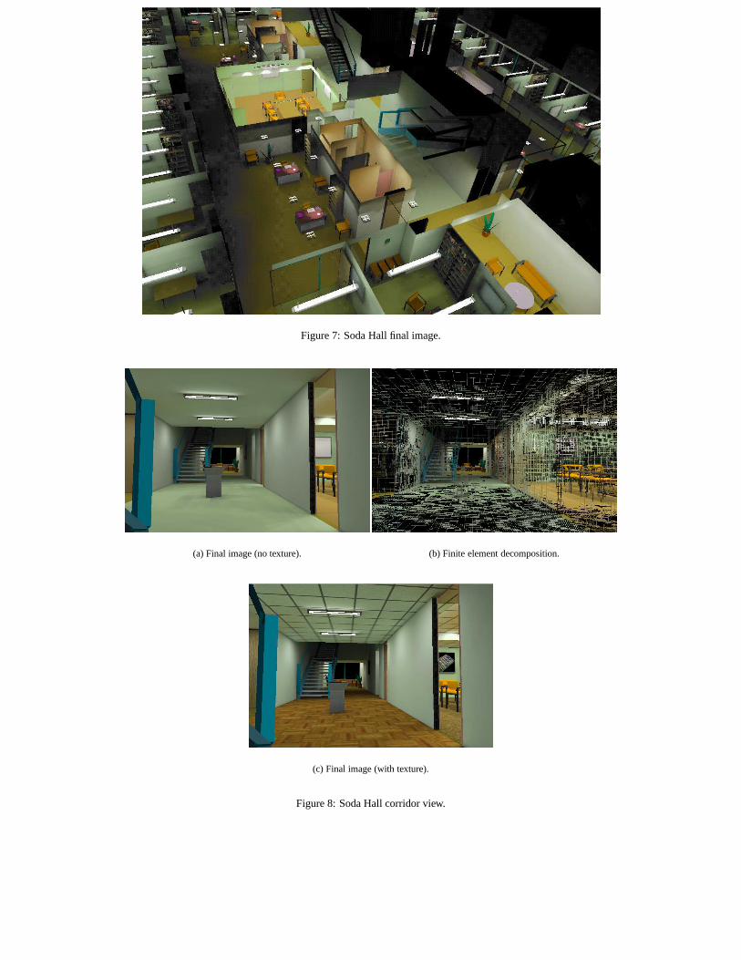
Figure 7: Soda Hall final image.
(a) Final image (no texture). (b) Finite element decomposition.
(c) Final image (with texture).
Figure 8: Soda Hall corridor view.


![3[1]. Graphics Hardware II](https://img.pdfslide.us/doc/110x75/547834d45906b55f318b4785/31-graphics-hardware-ii.jpg)