Embed Size (px)
Citation preview
FormForm
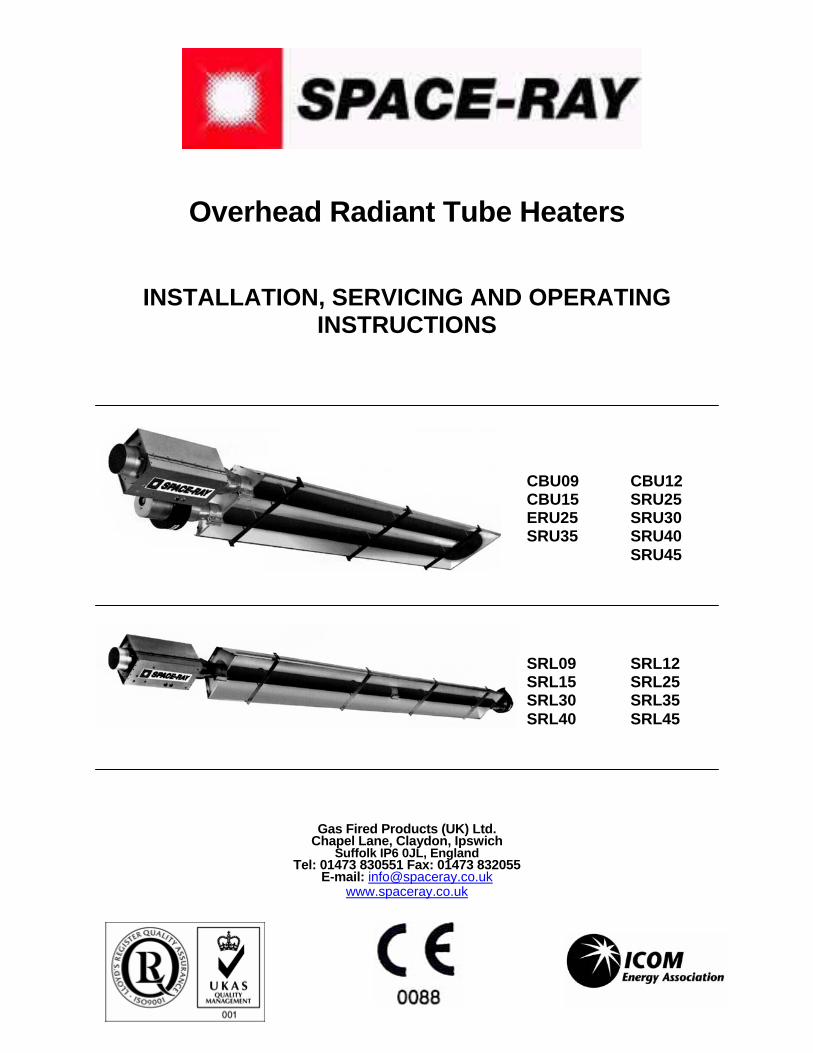
Overhead Radiant Tube Heaters
INSTALLATION, SERVICING AND OPERATING INSTRUCTIONS
Gas Fired Products (UK) Ltd. Chapel Lane, Claydon, Ipswich
Suffolk IP6 0JL, England Tel: 01473 830551 Fax: 01473 832055
E-mail: [email protected] www.spaceray.co.uk
CBU09 CBU12 CBU15 SRU25 ERU25 SRU30 SRU35 SRU40 SRU45
SRL09 SRL12 SRL15 SRL25 SRL30 SRL35 SRL40 SRL45

Form 483S Rev Jan 09 Page 1 of 53
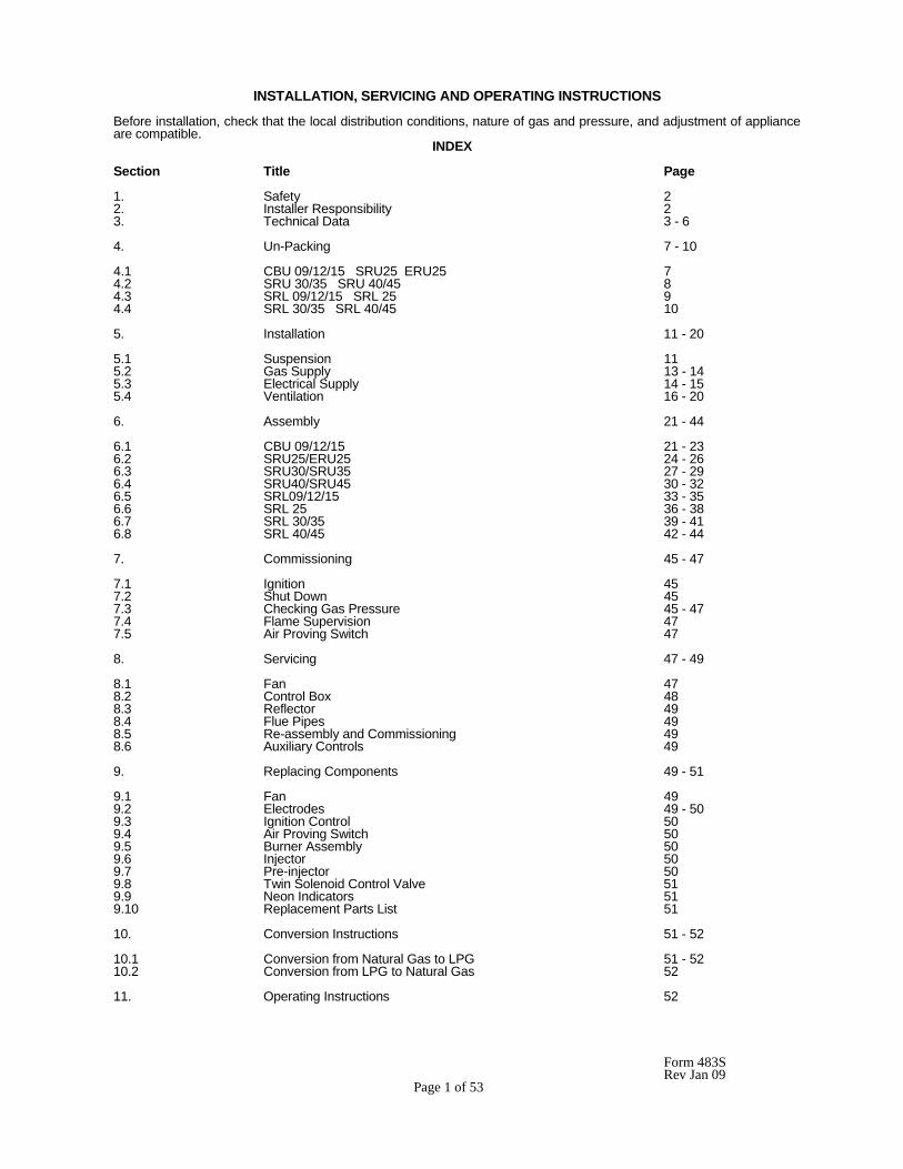
INSTALLATION, SERVICING AND OPERATING INSTRUCTIONS Before installation, check that the local distribution conditions, nature of gas and pressure, and adjustment of appliance are compatible. INDEX Section Title Page 1. Safety 2 2. Installer Responsibility 2 3. Technical Data 3 - 6 4. Un-Packing 7 - 10 4.1 CBU 09/12/15 SRU25 ERU25 7 4.2 SRU 30/35 SRU 40/45 8 4.3 SRL 09/12/15 SRL 25 9 4.4 SRL 30/35 SRL 40/45 10 5. Installation 11 - 20 5.1 Suspension 11 5.2 Gas Supply 13 - 14 5.3 Electrical Supply 14 - 15 5.4 Ventilation 16 - 20 6. Assembly 21 - 44 6.1 CBU 09/12/15 21 - 23 6.2 SRU25/ERU25 24 - 26 6.3 SRU30/SRU35 27 - 29 6.4 SRU40/SRU45 30 - 32 6.5 SRL09/12/15 33 - 35 6.6 SRL 25 36 - 38 6.7 SRL 30/35 39 - 41 6.8 SRL 40/45 42 - 44 7. Commissioning 45 - 47 7.1 Ignition 45 7.2 Shut Down 45 7.3 Checking Gas Pressure 45 - 47 7.4 Flame Supervision 47 7.5 Air Proving Switch 47 8. Servicing 47 - 49 8.1 Fan 47 8.2 Control Box 48 8.3 Reflector 49 8.4 Flue Pipes 49 8.5 Re-assembly and Commissioning 49 8.6 Auxiliary Controls 49 9. Replacing Components 49 - 51 9.1 Fan 49 9.2 Electrodes 49 - 50 9.3 Ignition Control 50 9.4 Air Proving Switch 50 9.5 Burner Assembly 50 9.6 Injector 50 9.7 Pre-injector 50 9.8 Twin Solenoid Control Valve 51 9.9 Neon Indicators 51 9.10 Replacement Parts List 51 10. Conversion Instructions 51 - 52 10.1 Conversion from Natural Gas to LPG 51 - 52 10.2 Conversion from LPG to Natural Gas 52 11. Operating Instructions 52
Form 483S Rev Jan 09 Page 2 of 53
INSTALLATION, SERVICING & OPERATING INSTRUCTIONS 1. SAFETY This heater is a self-contained overhead radiant tube heater designed for non-domestic use. Safety information required during installation and operation of this heater is provided in this manual and the labels on the product. The installation, service and maintenance of this heater must be performed by a contractor qualified in the installation and service of gas fired heating equipment.
All personnel in contact with the heater must read, and understand, all safety information, instructions and labels before operation. The following symbols will be used in this manual to indicate important safety information.
Warning instructions must be followed to prevent or avoid hazards which may cause serious injury, property damage or death.
Caution instructions must be followed to prevent incorrect operation or installation of the heater which may cause minor injury or property damage
2. INSTALLER RESPONSIBILITY
The installer is responsible for the following:
• The heater and venting, as well as electrical and gas supplies must be installed in accordance with these installation instructions and any applicable codes and regulations.
• Every heater shall be located with respect to building construction and other equipment so as to permit access to the heater.
• Each installer must follow the clearances to combustibles materials for the heaters.
• Install the heater so that the supports and hangers are correctly spaced in accordance with these instructions. The heater must be supported by materials having a working load limit of at least 52kg.
• Supply the owner with a copy of these Installation and Operation Instructions.
• Never use the heater as a support for a ladder or other access equipment. Do not hang anything from the heater.
• Supply all installation materials necessary that are not included with the heater.
Form 483S Rev Jan 09 Page 3 of 53
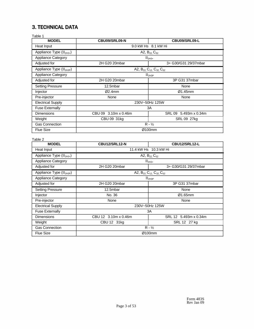
3. TECHNICAL DATA Table 1
MODEL CBU09/SRL09-N CBU09/SRL09-L Heat Input 9.0 kW Hs 8.1 kW Hi Appliance Type (II2H3+) A2, B22, C52 Appliance Category II2H3+ Adjusted for 2H G20 20mbar 3+ G30/G31 29/37mbar Appliance Type (II2H3P) A2, B22, C12, C32, C52 Appliance Category II2H3P Adjusted for 2H G20 20mbar 3P G31 37mbar Setting Pressure 12.5mbar None Injector Ø2.4mm Ø1.45mm Pre-injector None None Electrical Supply 230V~50Hz 125W Fuse Externally 3A Dimensions CBU 09 3.10m x 0.46m SRL 09 5.493m x 0.34m Weight CBU 09 31kg SRL 09 27kg Gas Connection R - ½ Flue Size Ø100mm
Table 2
MODEL CBU12/SRL12-N CBU12/SRL12-L Heat Input 11.4 kW Hs 10.3 kW Hi Appliance Type (II2H3+) A2, B22, C52 Appliance Category II2H3+ Adjusted for 2H G20 20mbar 3+ G30/G31 29/37mbar Appliance Type (II2H3P) A2, B22, C12, C32, C52 Appliance Category II2H3P Adjusted for 2H G20 20mbar 3P G31 37mbar Setting Pressure 12.5mbar None Injector No. 36 Ø1.65mm Pre-injector None None Electrical Supply 230V~50Hz 125W Fuse Externally 3A Dimensions CBU 12 3.10m x 0.46m SRL 12 5.493m x 0.34m Weight CBU 12 31kg SRL 12 27 kg Gas Connection R - ½ Flue Size Ø100mm
Form 483S Rev Jan 09 Page 4 of 53
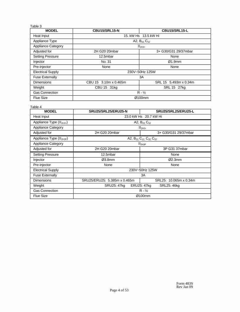
Table 3 MODEL CBU15/SRL15-N CBU15/SRL15-L Heat Input 15. kW Hs 13.5 kW Hi Appliance Type A2, B22, C52 Appliance Category II2H3+ Adjusted for 2H G20 20mbar 3+ G30/G31 29/37mbar Setting Pressure 12.5mbar None Injector No. 31 Ø1.9mm Pre-injector None None Electrical Supply 230V~50Hz 125W Fuse Externally 3A Dimensions CBU 15 3.10m x 0.465m SRL 15 5.493m x 0.34m Weight CBU 15 31kg SRL 15 27kg Gas Connection R - ½ Flue Size Ø100mm
Table 4
MODEL SRU25/SRL25/ERU25-N SRU25/SRL25/ERU25-L Heat Input 23.0 kW Hs 20.7 kW Hi Appliance Type (II2H3+) A2, B22, C52 Appliance Category II2H3+ Adjusted for 2H G20 20mbar 3+ G30/G31 29/37mbar Appliance Type (II2H3P) A2, B22, C12, C32, C52 Appliance Category II2H3P Adjusted for 2H G20 20mbar 3P G31 37mbar Setting Pressure 12.5mbar None Injector Ø3.8mm Ø2.3mm Pre-injector None None Electrical Supply 230V~50Hz 125W Fuse Externally 3A Dimensions SRU25/ERU25: 5.385m x 0.465m SRL25: 10.065m x 0.34m Weight SRU25: 47kg ERU25: 47kg SRL25: 46kg Gas Connection R - ½ Flue Size Ø100mm
Form 483S Rev Jan 09 Page 5 of 53
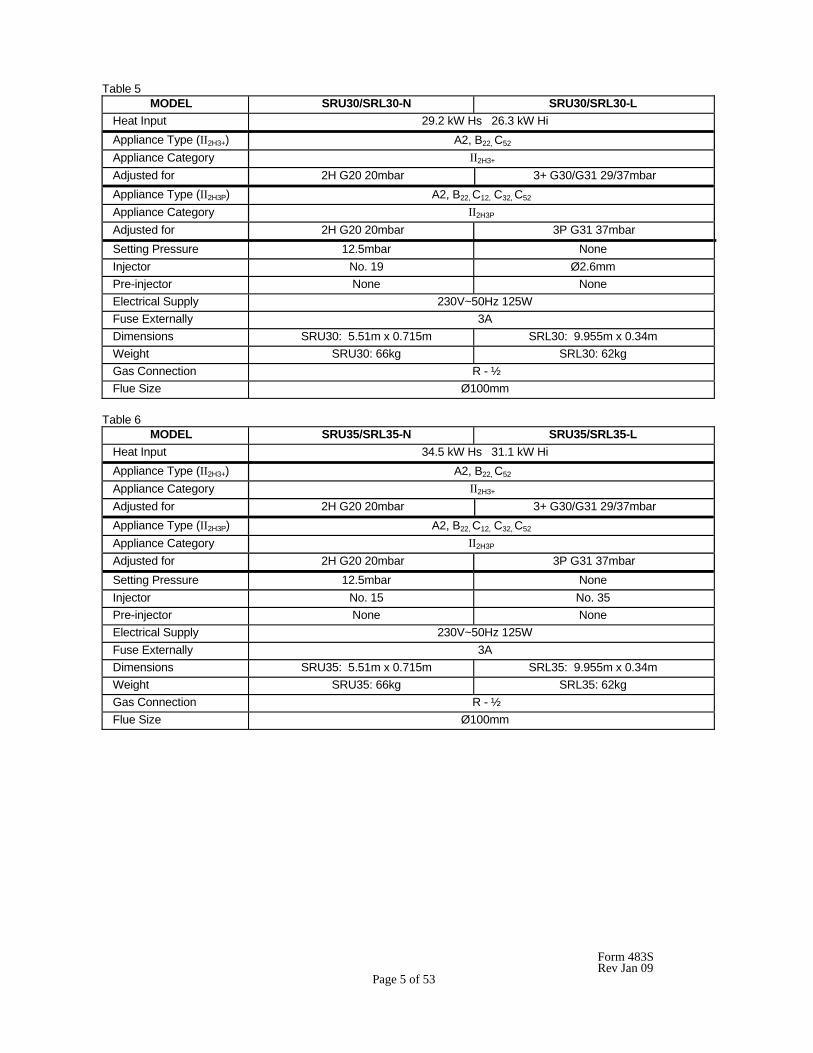
Table 5 MODEL SRU30/SRL30-N SRU30/SRL30-L Heat Input 29.2 kW Hs 26.3 kW Hi Appliance Type (II2H3+) A2, B22, C52 Appliance Category II2H3+ Adjusted for 2H G20 20mbar 3+ G30/G31 29/37mbar Appliance Type (II2H3P) A2, B22, C12, C32, C52 Appliance Category II2H3P Adjusted for 2H G20 20mbar 3P G31 37mbar Setting Pressure 12.5mbar None Injector No. 19 Ø2.6mm Pre-injector None None Electrical Supply 230V~50Hz 125W Fuse Externally 3A Dimensions SRU30: 5.51m x 0.715m SRL30: 9.955m x 0.34m Weight SRU30: 66kg SRL30: 62kg Gas Connection R - ½ Flue Size Ø100mm
Table 6
MODEL SRU35/SRL35-N SRU35/SRL35-L Heat Input 34.5 kW Hs 31.1 kW Hi Appliance Type (II2H3+) A2, B22, C52 Appliance Category II2H3+ Adjusted for 2H G20 20mbar 3+ G30/G31 29/37mbar Appliance Type (II2H3P) A2, B22, C12, C32, C52 Appliance Category II2H3P Adjusted for 2H G20 20mbar 3P G31 37mbar Setting Pressure 12.5mbar None Injector No. 15 No. 35 Pre-injector None None Electrical Supply 230V~50Hz 125W Fuse Externally 3A Dimensions SRU35: 5.51m x 0.715m SRL35: 9.955m x 0.34m Weight SRU35: 66kg SRL35: 62kg Gas Connection R - ½ Flue Size Ø100mm
Form 483S Rev Jan 09 Page 6 of 53
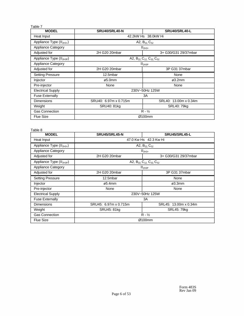
Table 7 MODEL SRU40/SRL40-N SRU40/SRL40-L Heat Input 42.2kW Hs 38.0kW Hi Appliance Type (II2H3+) A2, B22, C52 Appliance Category II2H3+ Adjusted for 2H G20 20mbar 3+ G30/G31 29/37mbar Appliance Type (II2H3P) A2, B22, C12, C32, C52 Appliance Category II2H3P Adjusted for 2H G20 20mbar 3P G31 37mbar Setting Pressure 12.5mbar None Injector ø5.0mm ø3.2mm Pre-injector None None Electrical Supply 230V~50Hz 125W Fuse Externally 3A Dimensions SRU40: 6.97m x 0.715m SRL40: 13.00m x 0.34m Weight SRU40: 81kg SRL40: 79kg Gas Connection R - ½ Flue Size Ø100mm
Table 8
MODEL SRU45/SRL45-N SRU45/SRL45-L Heat Input 47.0 Kw Hs 42.3 Kw Hi Appliance Type (II2H3+) A2, B22, C52 Appliance Category II2H3+ Adjusted for 2H G20 20mbar 3+ G30/G31 29/37mbar Appliance Type (II2H3P) A2, B22, C12, C32, C52 Appliance Category II2H3P Adjusted for 2H G20 20mbar 3P G31 37mbar Setting Pressure 12.5mbar None Injector ø5.4mm ø3.3mm Pre-injector None None Electrical Supply 230V~50Hz 125W Fuse Externally 3A Dimensions SRU45: 6.97m x 0.715m SRL45: 13.00m x 0.34m Weight SRU45: 81kg SRL45: 79kg Gas Connection R - ½ Flue Size Ø100mm
Form 483S Rev Jan 09 Page 7 of 53
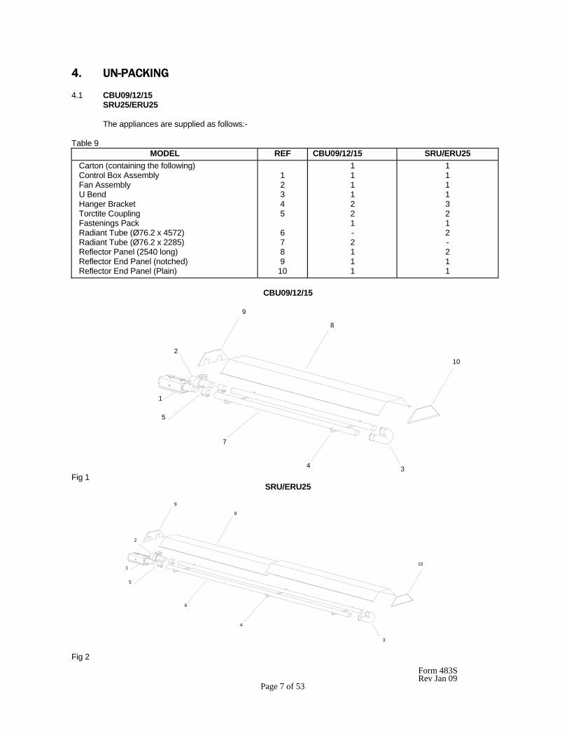
4. UN-PACKING 4.1 CBU09/12/15 SRU25/ERU25 The appliances are supplied as follows:- Table 9
MODEL REF CBU09/12/15 SRU/ERU25 Carton (containing the following) Control Box Assembly Fan Assembly U Bend Hanger Bracket Torctite Coupling Fastenings Pack Radiant Tube (Ø76.2 x 4572) Radiant Tube (Ø76.2 x 2285) Reflector Panel (2540 long) Reflector End Panel (notched) Reflector End Panel (Plain)
1 2 3 4 5 6 7 8 9 10
1 1 1 1 2 2 1 - 2 1 1 1
1 1 1 1 3 2 1 2 - 2 1 1
CBU09/12/15
Fig 1 SRU/ERU25
Fig 2
9
8
10
7
4
1
2
5
5
1
2
9
8
3
10
4
6
Form 483S Rev Jan 09 Page 8 of 53
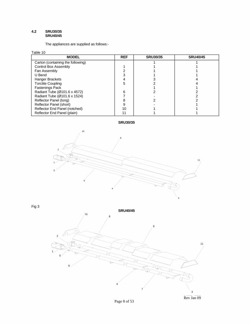
4.2 SRU30/35 SRU40/45 The appliances are supplied as follows:- Table 10
MODEL REF SRU30/35 SRU40/45 Carton (containing the following) Control Box Assembly Fan Assembly U Bend Hanger Brackets Torctite Coupling Fastenings Pack Radiant Tube (Ø101.6 x 4572) Radiant Tube (Ø101.6 x 1524) Reflector Panel (long) Reflector Panel (short) Reflector End Panel (notched) Reflector End Panel (plain)
1 2 3 4 5 6 7 8 9 10 11
1 1 1 1 3 2 1 2 - 2 - 1 1
1 1 1 1 4 4 1 2 2 2 1 1 1
SRU30/35
Fig 3 SRU40/45
4
6
5
1
3
11
2
10
8
7
4
5
9
6
1
2
8
3
11
Form 483S Rev Jan 09 Page 9 of 53
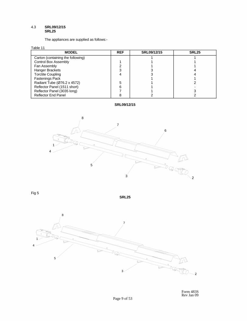
4.3 SRL09/12/15 SRL25 The appliances are supplied as follows:- Table 11
MODEL REF SRL09/12/15 SRL25 Carton (containing the following) Control Box Assembly Fan Assembly Hanger Brackets Torctite Coupling Fastenings Pack Radiant Tube (Ø76.2 x 4572) Reflector Panel (1511 short) Reflector Panel (3035 long) Reflector End Panel
1 2 3 4 5 6 7 8
1 1 1 3 3 1 1 1 1 2
1 1 1 4 4 1 2 - 3 2
SRL09/12/15
Fig 5
SRL25
3
5
1
4
8
6
7
8
7
3
1
4
5
Form 483S Rev Jan 09 Page 10 of 53
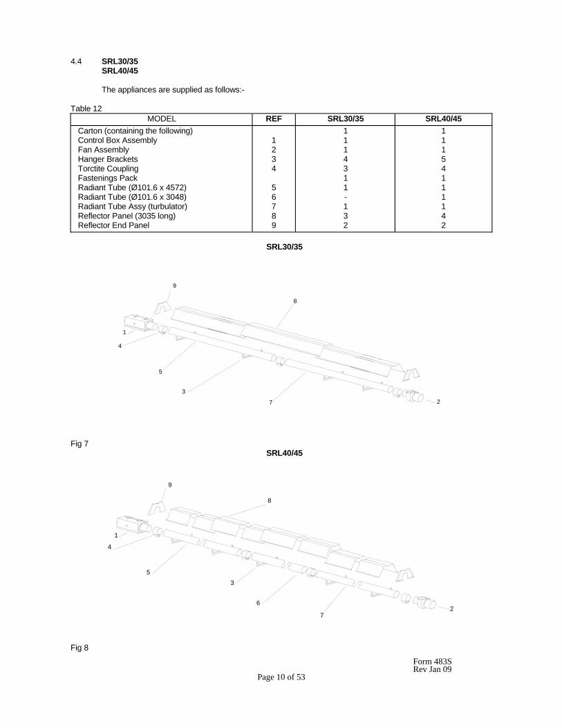
4.4 SRL30/35 SRL40/45 The appliances are supplied as follows:- Table 12
MODEL REF SRL30/35 SRL40/45 Carton (containing the following) Control Box Assembly Fan Assembly Hanger Brackets Torctite Coupling Fastenings Pack Radiant Tube (Ø101.6 x 4572) Radiant Tube (Ø101.6 x 3048) Radiant Tube Assy (turbulator) Reflector Panel (3035 long) Reflector End Panel
1 2 3 4 5 6 7 8 9
1 1 1 4 3 1 1 - 1 3 2
1 1 1 5 4 1 1 1 1 4 2
SRL30/35
Fig 7
SRL40/45
Fig 8
3
5
4
1
7
9
2
8
53
2
1
9
8
4
6
7
Form 483S Rev Jan 09 Page 11 of 53
5. INSTALLATION
Not withstanding their limited scope, the appliance should be installed in accordance with the relevant provisions of any National Gas Safety (Installation and Use) Regulations. Due account should also be taken of any obligations arising from any National Heath and Safety at Work Regulations, National and Local Building Regulations and National Electrical Wiring Regulations. The appliance must be installed, and where necessary, converted for use on other gases, by a qualified installer.
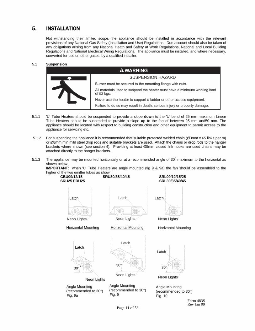
5.1 Suspension
��������������������� ����� ���������������������
������������������ �������������������������������������� ������� �� ���������
������������������� ����� ����������� �� ��������������������
�������� �� �� ������������������ ����� �����!���� ���� ������������
"#"$%�"&'��(�)�*+
5.1.1 'U' Tube Heaters should be suspended to provide a slope down to the 'U' bend of 25 mm maximum Linear
Tube Heaters should be suspended to provide a slope up to the fan of between 25 mm and50 mm. The appliance should be located with respect to building construction and other equipment to permit access to the appliance for servicing etc.
5.1.2 For suspending the appliance it is recommended that suitable protected welded chain (Ø3mm x 65 links per m)
or Ø8mm min mild steel drop rods and suitable brackets are used. Attach the chains or drop rods to the hanger brackets where shown (see section 4). Providing at least Ø5mm closed link hooks are used chains may be attached directly to the hanger brackets.
5.1.3 The appliance may be mounted horizontally or at a recommended angle of 300 maximum to the horizontal as
shown below. IMPORTANT: when 'U' Tube Heaters are angle mounted (fig 9 & 9a) the fan should be assembled to the higher of the two emitter tubes as shown.
CBU09/12/15 SRU30/35/40/45 SRL09/12/15/25 SRU25 ERU25 SRL30/35/40/45
Horizontal Mounting Horizontal Mounting Horizontal Mounting
Angle Mounting(recommended to 30°)Fig. 9a
Angle Mounting(recommended to 30°)Fig. 9
Angle Mounting(recommended to 30°)Fig. 10
Latch Latch Latch
LatchLatch
Latch
Neon LightsNeon Lights Neon Lights
Neon LightsNeon Lights Neon Lights
30°30° 30°
Form 483S Rev Jan 09 Page 12 of 53
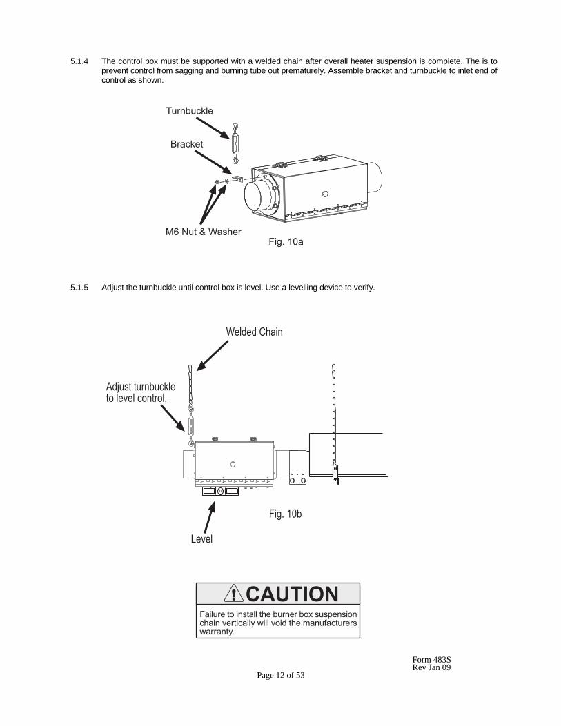
5.1.4 The control box must be supported with a welded chain after overall heater suspension is complete. The is to prevent control from sagging and burning tube out prematurely. Assemble bracket and turnbuckle to inlet end of control as shown. 5.1.5 Adjust the turnbuckle until control box is level. Use a levelling device to verify.
0��������
������
12����3�4����������56�
��!����������� �������� �� ��
�����56
/����
4������-����
�������� ����������������� .��������� ����������������������� ��������������������������
Form 483S Rev Jan 09 Page 13 of 53
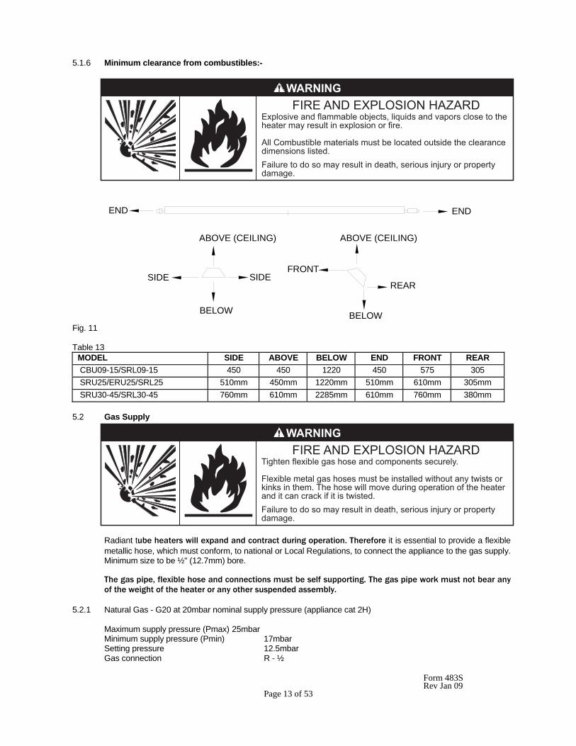
5.1.6 Minimum clearance from combustibles:-
END END
ABOVE (CEILING) ABOVE (CEILING)
BELOW BELOW
SIDE SIDEFRONT
REAR
Fig. 11 Table 13
MODEL SIDE ABOVE BELOW END FRONT REAR CBU09-15/SRL09-15 450 450 1220 450 575 305 SRU25/ERU25/SRL25 510mm 450mm 1220mm 510mm 610mm 305mm SRU30-45/SRL30-45 760mm 610mm 2285mm 610mm 760mm 380mm
5.2 Gas Supply
Radiant tube heaters will expand and contract during operation. Therefore it is essential to provide a flexible metallic hose, which must conform, to national or Local Regulations, to connect the appliance to the gas supply. Minimum size to be ½" (12.7mm) bore. The gas pipe, flexible hose and connections must be self supporting. The gas pipe work must not bear any of the weight of the heater or any other suspended assembly.
5.2.1 Natural Gas - G20 at 20mbar nominal supply pressure (appliance cat 2H) Maximum supply pressure (Pmax) 25mbar Minimum supply pressure (Pmin) 17mbar Setting pressure 12.5mbar Gas connection R - ½
%.�� ������������������ !��� ���������������� ����� ��� �����������������������.�� �� �� �������
����- ����������������������� ����� ������������������������� ���������
�������� �� �� ������������������ ����� �����!���� ���� �����������
0���������.��������� �������� �� ��������������
���.�������������� ���������������������� ����������� ���������������0���� ��������� ���������� ����� �� ����������������������������������������
�������� �� �� ������������������ ����� �����!���� ���� �����������
Form 483S Rev Jan 09 Page 14 of 53
5.2.1.1 Installation pipes should be fitted in accordance with National and Local Regulations. Pipes of a smaller size than the heater connection (R - ½) should not be used and the pipework must be designed to achieve a gas supply pressure between the maximum and minimum values stated above, measured at the appliance inlet pressure test point.
A union service cock MUST be fitted as close as practicable upstream of the heater to enable the gas train to be removed for maintenance or repair.
5.2.1.2 Check that the gas fuel on the burner data plate matches the fuel for the application. 5.2.2 LPG - G30/G31 at 29/37mbar nominal supply pressure (appliance cat. 3+). Maximum supply pressure (Pmax): G30 - 35mbar G31 - 45mbar Minimum supply pressure (Pmin): G30 - 20mbar G31 - 25mbar Note:- for appliance cat 3+ the governor is not operational Gas connections: R - ½ 5.2.2.1 The appliance should be connected to a permanent piped supply of LPG with pipes of adequate size to achieve
a gas supply pressure between the maximum and minimum valves stated above, measured at the appliance inlet pressure test point.
5.2.3 The complete installation MUST be tested for soundness in accordance with National or Local Regulations. 5.3 Electrical Supply
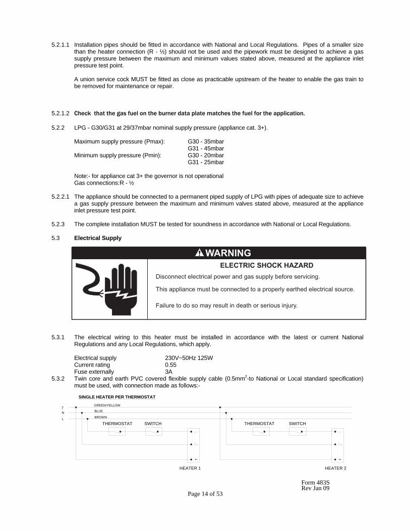
5.3.1 The electrical wiring to this heater must be installed in accordance with the latest or current National Regulations and any Local Regulations, which apply. Electrical supply 230V~50Hz 125W Current rating 0.55 Fuse externally 3A 5.3.2 Twin core and earth PVC covered flexible supply cable (0.5mm2-to National or Local standard specification)
must be used, with connection made as follows:-
THERMOSTAT SWITCHTHERMOSTAT SWITCH
HEATER 1 HEATER 2
GREEN/YELLOW
BLUE
BROWN
7N
L
7 7
SINGLE HEATER PER THERMOSTAT
�������� �� �� ������������������� ������ �����!����
0��������������������� ������� ����� ������������������������ �����
+��� ���������������� ��������������������� �������������
�������������� ���
Form 483S Rev Jan 09 Page 15 of 53
7
L
N
HEATER 1
7
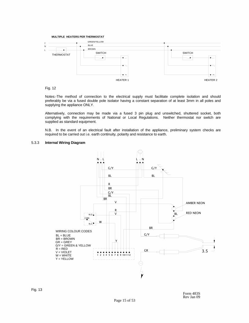
MULTIPLE HEATERS PER THERMOSTAT
SWITCHBROWN
BLUE
GREEN/YELLOW
HEATER 2
7
SWITCHTHERMOSTAT
Fig. 12
Notes:-The method of connection to the electrical supply must facilitate complete isolation and should preferably be via a fused double pole isolator having a constant separation of at least 3mm in all poles and supplying the appliance ONLY.
Alternatively, connection may be made via a fused 3 pin plug and unswitched, shuttered socket, both complying with the requirements of National or Local Regulations. Neither thermostat nor switch are supplied as standard equipment. N.B. In the event of an electrical fault after installation of the appliance, preliminary system checks are required to be carried out i.e. earth continuity, polarity and resistance to earth. 5.3.3 Internal Wiring Diagram
Fig. 13
N
G/Y
BL
RBRG/YBL
G/Y
BL
BRV
RV
W
N.O.
COM.
N.C.
BL
BR
G/Y
GR
Y
1 2 3 4 65 87 9 111210
L L N
WIRING COLOUR CODESBL = BLUEBR = BROWNGR = GREYG/Y = GREEN & YELLOW
V = VIOLETR = RED
W = WHITEY = YELLOW
AMBER NEON
RED NEON
3.5
Form 483S Rev Jan 09 Page 16 of 53
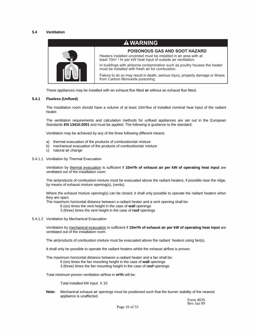
5.4 Ventilation
These appliances may be installed with an exhaust flue fitted or without an exhaust flue fitted.
5.4.1 Flueless (Unflued)
The installation room should have a volume of at least 10m³/kw of installed nominal heat input of the radiant heater. The ventilation requirements and calculation methods for unflued appliances are set out in the European Standards EN 13410:2001 and must be applied. The following is guidance to the standard: Ventilation may be achieved by any of the three following different means: a) thermal evacuation of the products of combustion/air mixture b) mechanical evacuation of the products of combustion/air mixture c) natural air change
5.4.1.1 Ventilation by Thermal Evacuation
Ventilation by thermal evacuation is sufficient if 10m³/h of exhaust air per kW of operating heat input are ventilated out of the installation room. The air/products of combustion mixture must be evacuated above the radiant heaters, if possible near the ridge, by means of exhaust mixture opening(s), (vents). Where the exhaust mixture opening(s) can be closed, it shall only possible to operate the radiant heaters when they are open. The maximum horizontal distance between a radiant heater and a vent opening shall be: 6 (six) times the vent height in the case of wall openings 3 (three) times the vent height in the case of roof openings
5.4.1.2 Ventilation by Mechanical Evacuation
Ventilation by mechanical evacuation is sufficient if 10m³/h of exhaust air per kW of operating heat input are ventilated out of the installation room.
The air/products of combustion mixture must be evacuated above the radiant heaters using fan(s). It shall only be possible to operate the radiant heaters whilst the exhaust airflow is proven. The maximum horizontal distance between a radiant heater and a fan shall be: 6 (six) times the fan mounting height in the case of wall openings 3 (three) times the fan mounting height in the case of roof openings Total minimum proven ventilation airflow in m³/h will be: Total installed kW input X 10 Note: Mechanical exhaust air openings must be positioned such that the burner stability of the nearest appliance is unaffected.
�������� �� �� ������������������ ����� �����!��� ��� ������������ ����������� ��-�� ��1 � .����� �� �����
&������������������ ����� ������� ����������� ������ ������������������������������������������� ��� ���� ��
(�����������������������������������������������������������56�7�8���������4���������� �� ����������������� ��
������������������� ���
Form 483S Rev Jan 09 Page 17 of 53
5.4.1.3 Ventilation by Natural Air Change
Gas-fired radiant heaters may be operated without any special exhaust system if the exhaust gases are discharged to the outside atmosphere by a sufficient natural air change in the installation room. Furthermore, no provision for thermal or mechanical ventilation is required in the following particular cases: Buildings with natural air change greater than 1.5 volumes per hour Buildings with a density of operating heat input not greater than 5W/m³
5.4.1.4 Air Supply
Air supply openings are required to admit air and shall be located below the radiant heaters. The total area of the unobstructed cross-sections of all the air supply openings shall not be smaller than the total area of the unobstructed cross-sections of all the exhaust openings. Slits and gaps of fixed cross-section can also be used as air supply openings. Where the air supply openings can be closed, it shall only be possible to operate the radiant heaters when they are open.
5.4.2 Flued
If the appliance is to be flued externally, then flue pipe of diameter stated in table 14, and complying with National and Local Regulations should be used.
IMPORTANT: When flued horizontally, the flue pipe must be arranged to provide a continuous rise from the appliance of 25mm per 1m length.
The ventilation requirements for flued appliances is set out in BS 6896:1991 and must be applied. The following is guidance to the standard: 5.4.2.1 Natural Ventilation
Low level ventilation shall be provided in all cases below the level of the heater(s). Up to and including 60kW - 4.5cm2/kW Over 60kW - 270cm2 + 2.25cm2 /kW in excess of 60kW total rated heat input. Where the air supply openings can be closed, it shall only be possible to operate the radiant heaters when they are open. 5.4.2.2 Mechanical Ventilation
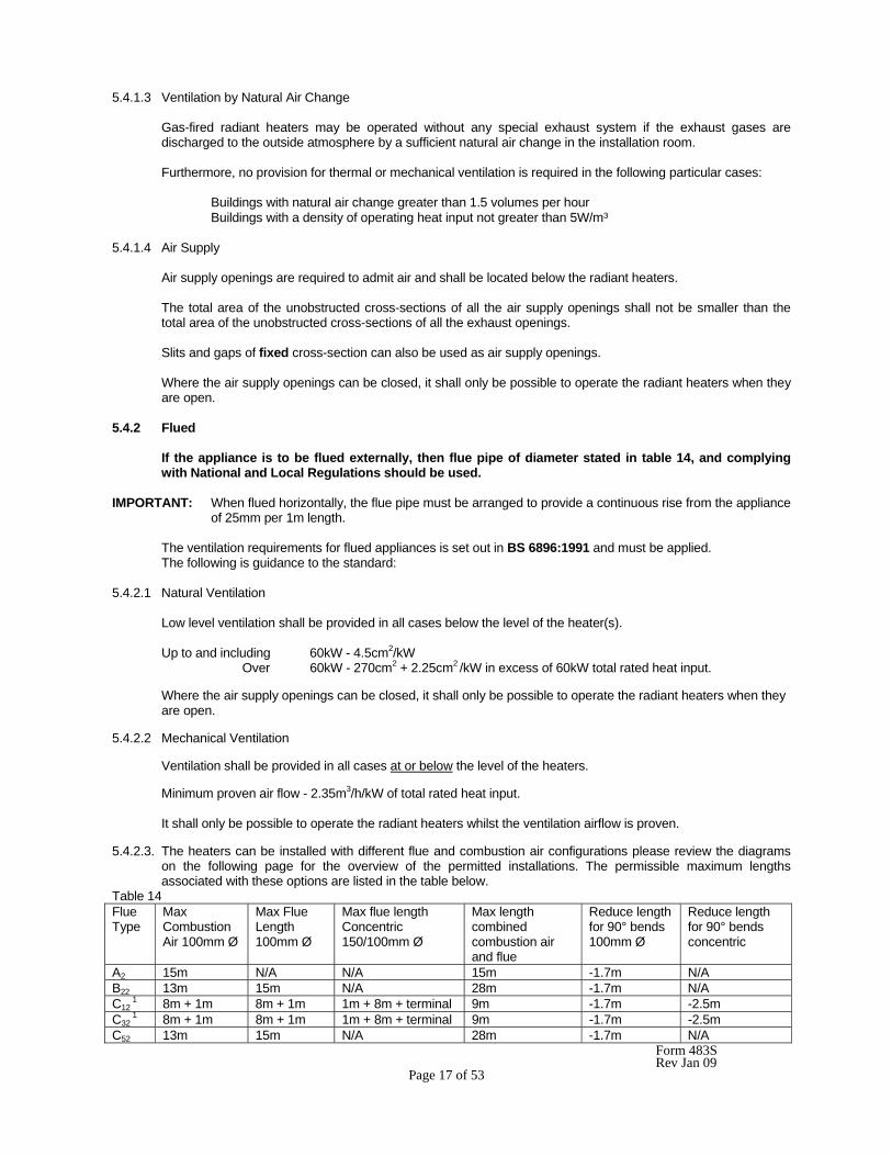
Ventilation shall be provided in all cases at or below the level of the heaters. Minimum proven air flow - 2.35m3/h/kW of total rated heat input. It shall only be possible to operate the radiant heaters whilst the ventilation airflow is proven. 5.4.2.3. The heaters can be installed with different flue and combustion air configurations please review the diagrams
on the following page for the overview of the permitted installations. The permissible maximum lengths associated with these options are listed in the table below.
Table 14 Flue Type
Max Combustion Air 100mm Ø
Max Flue Length 100mm Ø
Max flue length Concentric 150/100mm Ø
Max length combined combustion air and flue
Reduce length for 90° bends 100mm Ø
Reduce length for 90° bends concentric
A2 15m N/A N/A 15m -1.7m N/A B22 13m 15m N/A 28m -1.7m N/A C12
1 8m + 1m 8m + 1m 1m + 8m + terminal 9m -1.7m -2.5m C32
1 8m + 1m 8m + 1m 1m + 8m + terminal 9m -1.7m -2.5m C52 13m 15m N/A 28m -1.7m N/A
Form 483S Rev Jan 09 Page 18 of 53
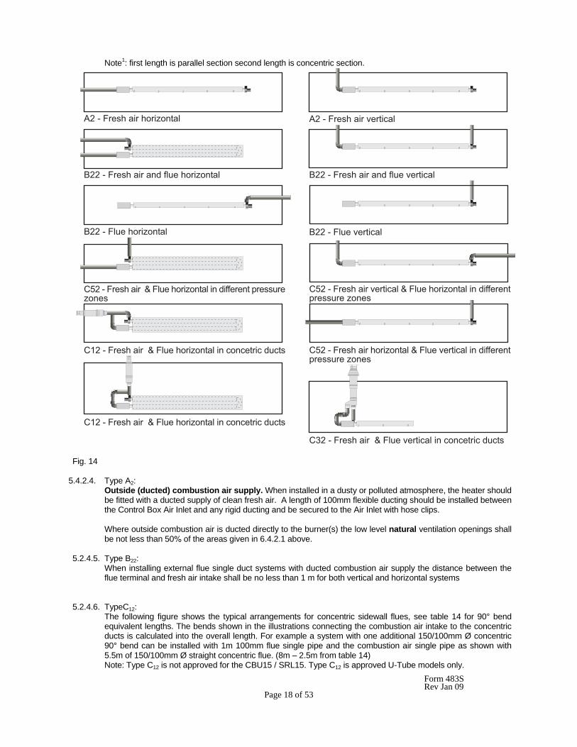
Note1: first length is parallel section second length is concentric section.
���9������������ ��: ��� ���9������������������
����9��������������������� ��: ��� ����9���������������������������
����9������� ��: ��� ����9�������������
-���9������������3������� ��: ������������������������: ���
-���9�������������������3������� ��: ������������������������: ���
-5��9������������3������� ��: �������� �����������
-5��9������������3������� ��: �������� �����������
-7��9������������3������������������ �����������
-���9������������ ��: ����3����������������������������������: ���
Fig. 14
5.4.2.4. Type A2: Outside (ducted) combustion air supply. When installed in a dusty or polluted atmosphere, the heater should
be fitted with a ducted supply of clean fresh air. A length of 100mm flexible ducting should be installed between the Control Box Air Inlet and any rigid ducting and be secured to the Air Inlet with hose clips.
Where outside combustion air is ducted directly to the burner(s) the low level natural ventilation openings shall be not less than 50% of the areas given in 6.4.2.1 above.
5.2.4.5. Type B22: When installing external flue single duct systems with ducted combustion air supply the distance between the
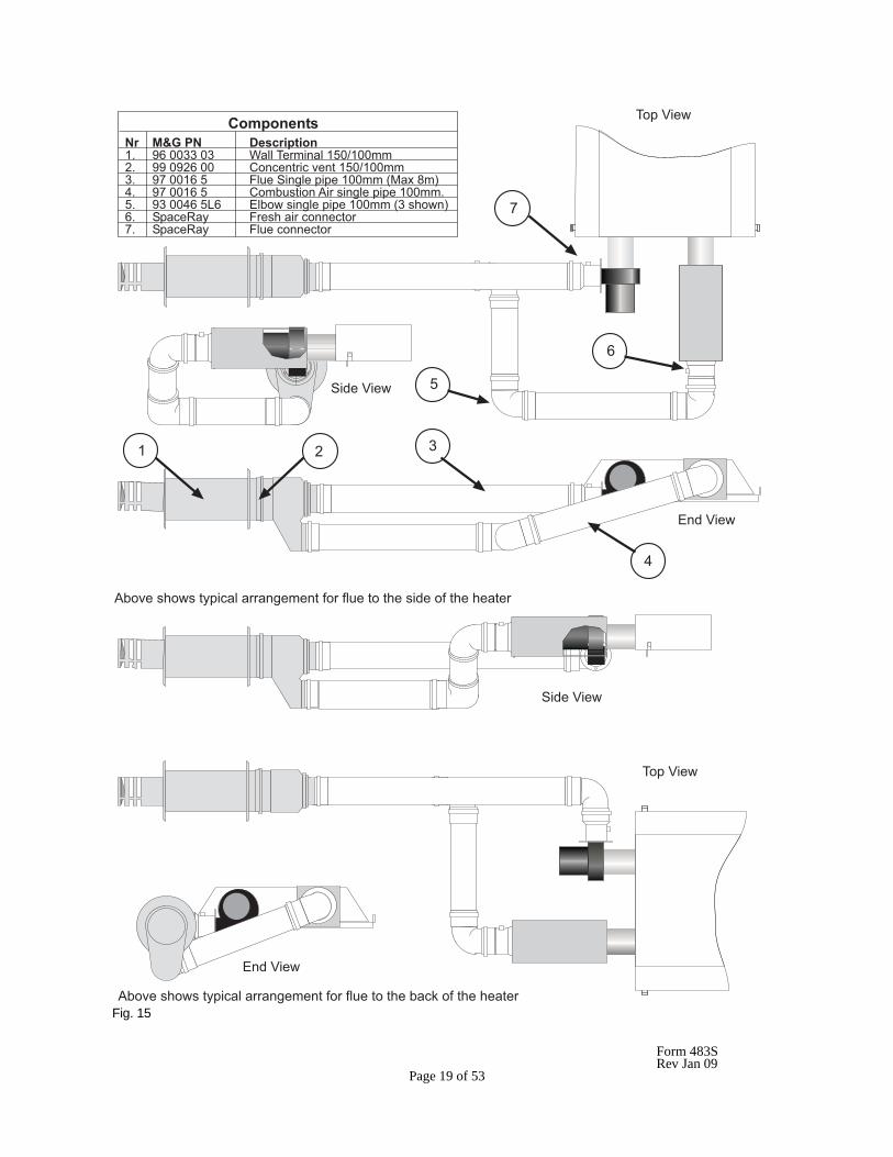
flue terminal and fresh air intake shall be no less than 1 m for both vertical and horizontal systems 5.2.4.6. TypeC12: The following figure shows the typical arrangements for concentric sidewall flues, see table 14 for 90° bend
equivalent lengths. The bends shown in the illustrations connecting the combustion air intake to the concentric ducts is calculated into the overall length. For example a system with one additional 150/100mm Ø concentric 90° bend can be installed with 1m 100mm flue single pipe and the combustion air single pipe as shown with 5.5m of 150/100mm Ø straight concentric flue. (8m – 2.5m from table 14)
Note: Type C12 is not approved for the CBU15 / SRL15. Type C12 is approved U-Tube models only.
Form 483S Rev Jan 09 Page 19 of 53
5 � 7
0 ��;���
"����;���
%���;���
"����;���
%���;���
0 ��;���
������������ ������ �����������5�� <2�6677�67 4����0��������5�68566���� <<�6<�2�66 - ������������5�68566��7�� <=�6652�� �����"�����������566���>1�.�?�@A� <=�6652�� - ���� ������������������566����� <7�66A2��/2 %� ��������������566���>7��� ��@2� "����*�� ����������� ���� �=� "����*�� ������ ���� �
� ����� ���������������������� ������� ��������� ����������
� ����� ���������������������� ������� �������� ����������
A
�
2
=
Fig. 15
Form 483S Rev Jan 09 Page 20 of 53
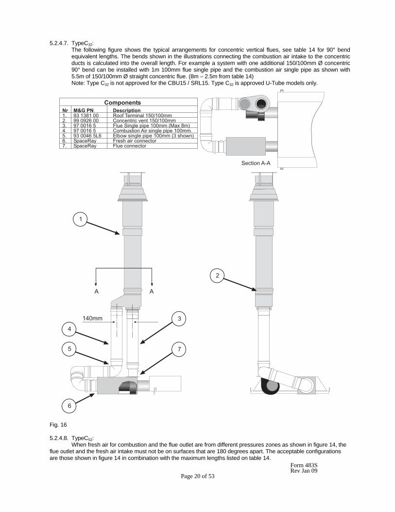
5.2.4.7. TypeC32: The following figure shows the typical arrangements for concentric vertical flues, see table 14 for 90° bend
equivalent lengths. The bends shown in the illustrations connecting the combustion air intake to the concentric ducts is calculated into the overall length. For example a system with one additional 150/100mm Ø concentric 90° bend can be installed with 1m 100mm flue single pipe and the combustion air single pipe as shown with 5.5m of 150/100mm Ø straight concentric flue. (8m – 2.5m from table 14)
Note: Type C32 is not approved for the CBU15 / SRL15. Type C32 is approved U-Tube models only.
Fig. 16 5.2.4.8. TypeC52: When fresh air for combustion and the flue outlet are from different pressures zones as shown in figure 14, the flue outlet and the fresh air intake must not be on surfaces that are 180 degrees apart. The acceptable configurations are those shown in figure 14 in combination with the maximum lengths listed on table 14.
������������ ������ �����������5�� <7�57?5�66 * ��0��������5�68566���� <<�6<�2�66 - ������������5�68566��7�� <=�6652�� �����"�����������566���>1�.�?�@A� <=�6652�� - ���� ������������������566����� <7�66A2��/2 %� ��������������566���>7��� ��@2� "����*�� ����������� ���� �=� "����*�� ������ ���� �
"��� ���9�
�
5
A
7
� �
�
2
=
5A6��
Form 483S Rev Jan 09 Page 21 of 53
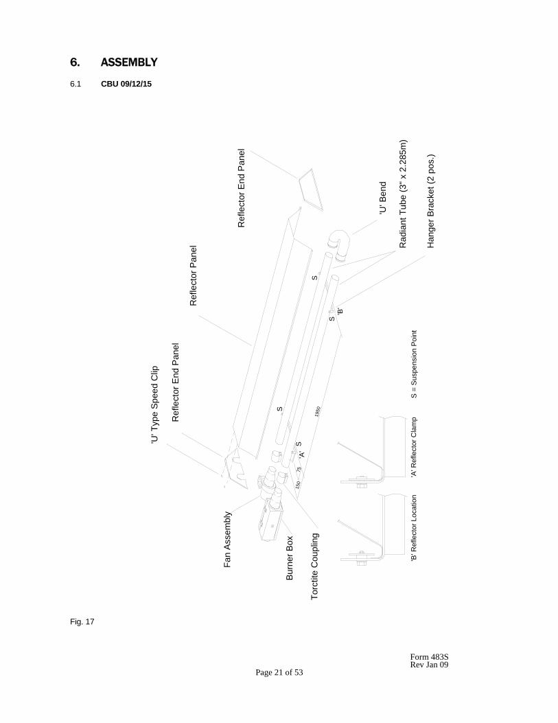
6. ASSEMBLY 6.1 CBU 09/12/15
Fig. 17
7515
0
1950
'U' T
ype
Spee
d C
lip
Ref
lect
or E
nd P
anel
Ref
lect
or P
anel
Ref
lect
or E
nd P
anel
'U' B
end
Rad
iant
Tub
e (3
" x 2
.285
m)
Han
ger B
rack
et (2
pos
.)
Bur
ner B
ox
Fan
Ass
embl
y
Torc
tite
Cou
plin
g'A
'S
S'B
'
S
S
'A' R
efle
ctor
Cla
mp
'B' R
efle
ctor
Loc
atio
nS
= S
uspe
nsio
n Po
int
Form 483S Rev Jan 09 Page 22 of 53
6.1.1 Remove the packaging/protection from the Radiant Tubes and ensure that they are clear internally. Place the
Radiant Tubes on trestles, providing 150mm minimum clearance above the floor and space 190mm apart with the ends of the tubes in line. Ensure that the welded seam of the tube is in contact with the hanger bracket (see 6.1.2 below) i.e. facing away from the reflector.
Assemble the U bend to the tubes with the two threaded holes facing upwards, ensuring that the U bend engages fully. Using two 5/16" BSW hexagon socket setscrews (from fastenings pack) secure the U bend to the Radiant Tubes.
IMPORTANT: Failure to assemble the Radiant tubes with their welded seam facing away from the reflector will void the manufactures warranty.
6.1.2 Assemble the two Hanger Brackets to the Radiant Tubes using two 'U' bolts per bracket (from fastenings pack)
and position along the Radiant Tubes as shown in Fig 17. Tighten the nuts sufficiently to retain the Hanger Brackets. Do not over tighten.
6.1.3 Place one Torctite Coupling over the open end of the R.H. Radiant Tube (viewed from the open end of the
tubes) ensuring that it engages fully, up to the stop. Assemble the Control Box to the R.H. Radiant Tube ensuring that it engages fully into the Torctite Coupling (up to the stop) and is positioned vertically with the door latch uppermost (see Fig 9a). Tighten the nuts of the Torctite Coupling to secure the Control Box to the Radiant Tube taking care to support the Control Box in line with the axis of the tube.
NOTE: Tighten the Torctite Coupling screws alternately whilst continually checking for slackness of the joint.
6.1.4 Place the second Torctite Coupling over the open end of the L.H. Radiant Tube ensuring that it engages fully,
up to the stop. Assemble the Fan Assembly to the LH Radiant Tube, ensuring that it engages fully into the Torctite Coupling (up to the stop) and is positioned as follows:- Horizontal Mounting: fan outlet horizontal and facing away from the adjacent Control Box for flueless applications and either horizontal or vertical (facing upwards) for flued applications. Angle Mounting: fan outlet vertical (facing upwards) for either flueless or flued applications. Tighten the nuts of the Torctite Coupling to secure the Fan Assembly tot he Radiant Tube taking care to support the Fan Assembly in line with the axis of the tube (see Fig. 9a).
NOTE: Tighten the Torctite Coupling screws alternately whilst continually checking for slackness of the joint.
6.1.5 Place the Reflector Panel onto the Hanger Brackets, positioning the Reflector at the Control Box end between the bracket and the Torctite Coupling. Clamp the Reflector to the Hanger Brackets using the retainers and M6 setscrews and washers (fastenings Pack - qty 4) as shown in Fig 17. 6.1.6 Position the Reflector End Panel (notched) over the Radiant Tubes and into the end of the Reflector Panel with
the End Panel flange flush with the end of the Reflector. Secure the Reflector End Panel to the Reflector Panel by use of 6 'U' type speed clips provided (fastenings pack); 2 clips per facet of Reflector Panel, as shown in Fig 17.
Repeat the procedure to attach the Reflector End Panel (plain) to the opposite end of the Reflector. 6.1.7 The appliance should now be raised and suspended from previously fixed chains or drop rods as detailed in
Section 5.1, at suspension points indicated in Fig 17. Rope or webbing slings should be used when lifting from above. If using a forklift to position the appliance, ensure that the appliance is balanced on the forks prior to lifting.
6.1.8 If combustion air is to be ducted to the appliance, attach a length of flexible ducting to the Air Inlet Adaptor of
the Control Box by the use of a suitable hoseclip. Attach the inlet end of the hose to any fixed ducting, also by the use of a suitable hoseclip, allowing for adequate movement of the appliance.
6.1.9 Connect the gas supply in accordance with Section 5.2 - Gas Supply, of these installation instructions.

Form 483S Rev Jan 09 Page 23 of 53
6.1.10 Using twin core and earth flexible supply cable, as specified in Section 5.3.2, suitable for 230V~50Hz 125W supply, connect the 3 pin electrical socket provided (fastenings pack) as follows:-
Brown (Red) - to terminal marked L Blue (Black) - to terminal marked N Green/Yellow - to terminal marked 7 External fuse rating required - 3A. See Section 3.3 for electricity supply requirements.
NOTE: It is important for the correct function of the appliance for the polarity of the electrical supply to be correct.
Form 483S Rev Jan 09 Page 24 of 53
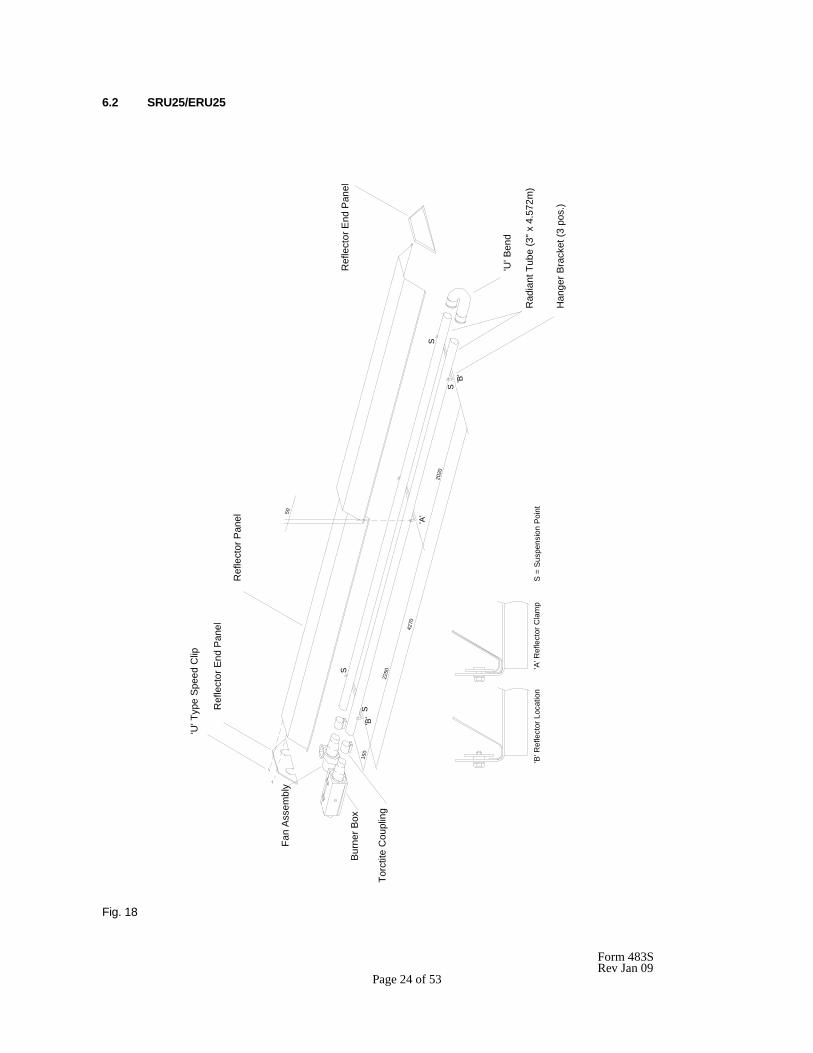
6.2 SRU25/ERU25
Fig. 18
Han
ger B
rack
et (3
pos
.)
Rad
iant
Tub
e (3
" x 4
.572
m)
150
'A' R
efle
ctor
Cla
mp
Torc
tite
Cou
plin
g
Burn
er B
ox
S =
Sus
pens
ion
Poin
t'B
' Ref
lect
or L
ocat
ion
S'B
'
2250S
S'B
'
S
Fan
Ass
embl
y
Ref
lect
or E
nd P
anel
'U' T
ype
Spee
d C
lip
Ref
lect
or P
anel
'U' B
end
Ref
lect
or E
nd P
anel
'A'
4270
2020
50
Form 483S Rev Jan 09 Page 25 of 53
6.2.1 Remove the packaging/protection from the Radiant Tubes and ensure that they are clear internally. Place the
Radiant Tubes on trestles, providing 150mm minimum clearance above the floor and space 190mm apart, with the ends of the tubes in line. Ensure that the welded seam of the tube is in contact with the hanger bracket (see 6.2.2 below) i.e. facing away from the reflector. Assemble the U bend to the tubes with the two threaded holes facing upwards, ensuring that the U bend engages fully. Using two 5/16" BSW hexagon socket setscrews (from Fastenings Pack) secure the U bend to the Radiant Tubes.
IMPORTANT: Failure to assemble the Radiant tubes with their welded seam facing away from the reflector will void the manufactures warranty. 6.2.2 Assemble the three Hanger Brackets to the Radiant Tubes using two 'U' bolts per bracket (from Fastenings
Pack) and position along the Radiant Tubes as shown in Fig 18. Tighten the nuts sufficiently to retain the Hanger Brackets. Do not over tighten.
6.2.3 Place one Torctite Coupling over the open end of the RH Radiant Tube (viewed from the open end of the tubes) ensuring that it engages fully, up to the stop. Assemble the Control Box to the RH Radiant Tube ensuring that it engages fully into the Torctite Coupling (up to the stop) and is positioned vertically with the door latch uppermost (see fig 9a). Tighten the nuts of the Torctite Coupling to secure the Control Box to the Radiant Tube, taking care to support the Control Box in line with the axis of the tube.
NOTE: Tighten the Torctite Coupling screws alternately whilst continually checking for slackness of the joint. 6.2.4 Place the second Torctite Coupling over the open end of the LH Radiant Tube ensuring that it engages fully, up
to the stop. Assemble the Fan Assembly to the LH Radiant Tube ensuring that it engages fully into the Torctite Coupling (up to the stop) and is positioned as follows:- Horizontal Mounting: fan outlet horizontal and facing away from the adjacent Control Box for flueless applications and either horizontal or vertical (facing upwards) for flued applications. Angle Mounting: fan outlet vertical (facing upwards) for either flueless or flued applications. Tighten the nuts of the Torctite Coupling to secure the Fan Assembly to the Radiant Tube taking care to support the Fan Assembly in line with the axis of the tube (see Fig. 9a).
NOTE: Tighten the Torctite Coupling screws alternately whilst continually checking for slackness of the joint. 6.2.5 Place the two Reflector Panels onto the Hanger Brackets and position to provide a 50mm overlap at the centre
arranged equally about the centre Hanger Bracket. Clamp the two Reflector Panels to the centre Hanger Bracket using two retainers and M6 setscrews and washers (fastening pack). Screw the remaining (4) retainers to the two outer Hanger Brackets to provide location for the Reflector Panel ends as shown in Fig. 18.
NOTE. The outer ends of the Reflector Panels will be free to move and compensate for expansion and contraction caused by temperature variation. 6.2.6 Position the Reflector End Panel (notched) over the Radiant Tubes and into the end of the Reflector Panel, with
the End Panel flange flush with the end of the Reflector. Secure the Reflector End Panel to the Reflector Panel by use of 6 - U type speed clips provided (fastenings pack); 2 clips per facet of Reflector Panel, as shown in Fig. 18.
Repeat the procedure to attach the Reflector End Panel (plain) to the opposite end of the Reflector. 6.2.7 The appliance should now be raised and suspended from previously fixed chains or drop rods as detailed in
Section 5.1, at suspension points indicated in Fig. 18. Rope or webbing slings should be used when lifting from above. If using a forklift to position the appliance, ensure that the appliance is balanced on the forks prior to lifting.
6.2.8 If combustion air is to be ducted to the appliance, attach a length of flexible ducting to the Air Inlet Adaptor of the Control Box by use of a suitable hoseclip. Attach the inlet end of the hose to any fixed ducting, also by use of a suitable hoseclip, allowing for adequate movement of the appliance. 6.2.9 Connect the gas supply in accordance with section 5.2 - Gas Supply, of these installation instructions.
Form 483S Rev Jan 09 Page 26 of 53
6.2.10 Using twin core and earth flexible supply cable, as specified in Section 5.3.2, suitable for 230V~50Hz 125W supply, connect the 3 pin electrical socket provided (fastening pack) as follows:-
Brown (Red) - to terminal marked L Blue (Black) - to terminal marked N Green/Yellow - to terminal marked 7 External fuse rating required - 3A See Section 3.3 for electricity supply requirements.
NOTE: It is important for the correct function of the appliance for the polarity of the electrical supply to be correct.
Form 483S Rev Jan 09 Page 27 of 53
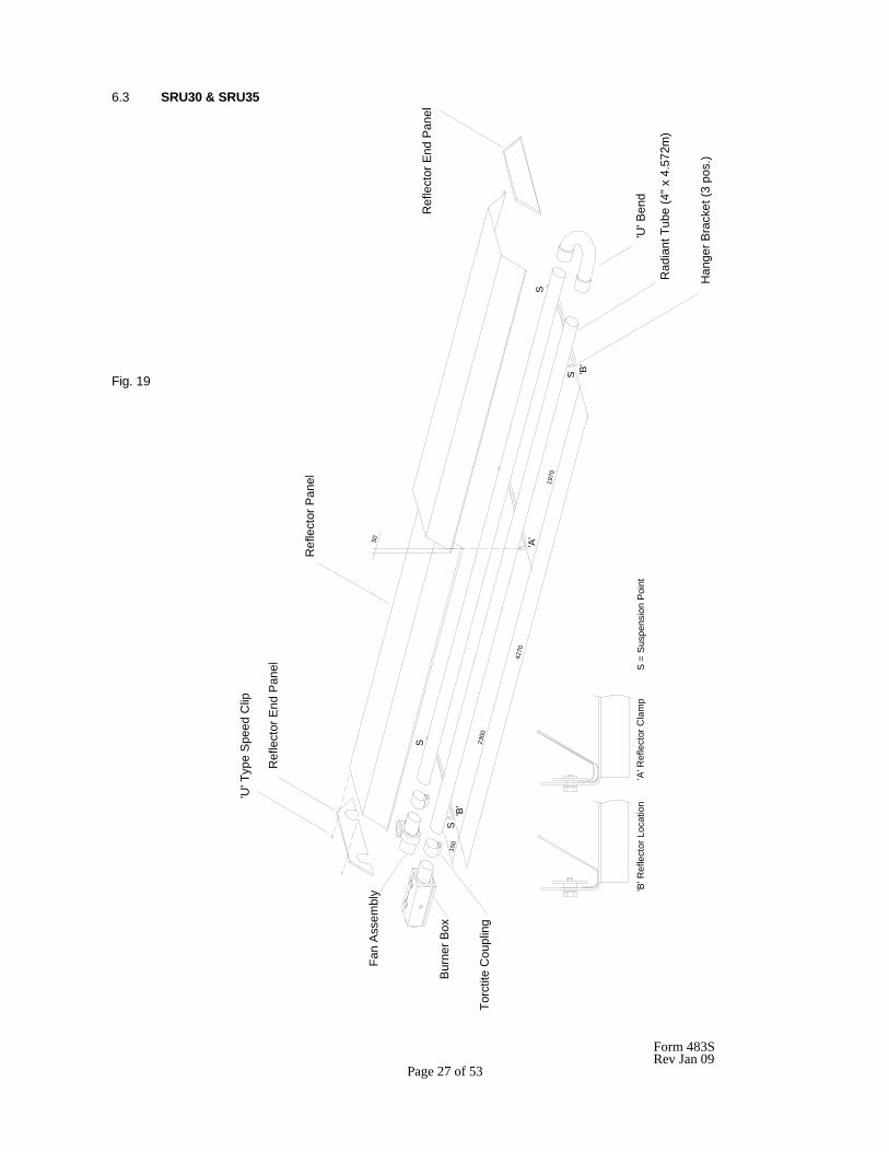
6.3 SRU30 & SRU35 Fig. 19
Han
ger B
rack
et (3
pos
.)
Rad
iant
Tub
e (4
" x 4
.572
m)
Torc
tite
Cou
plin
g
Bur
ner B
ox
S 'B'
S
'U' B
end
Ref
lect
or E
nd P
anel
Fan
Ass
embl
y
'U' T
ype
Spe
ed C
lip
Ref
lect
or E
nd P
anel
Ref
lect
or P
anel
'A' R
efle
ctor
Cla
mp
'B' R
efle
ctor
Loc
atio
nS
= S
uspe
nsio
n P
oint
4270
1970
2300
150
'A'
S
S
'B'
50
Form 483S Rev Jan 09 Page 28 of 53
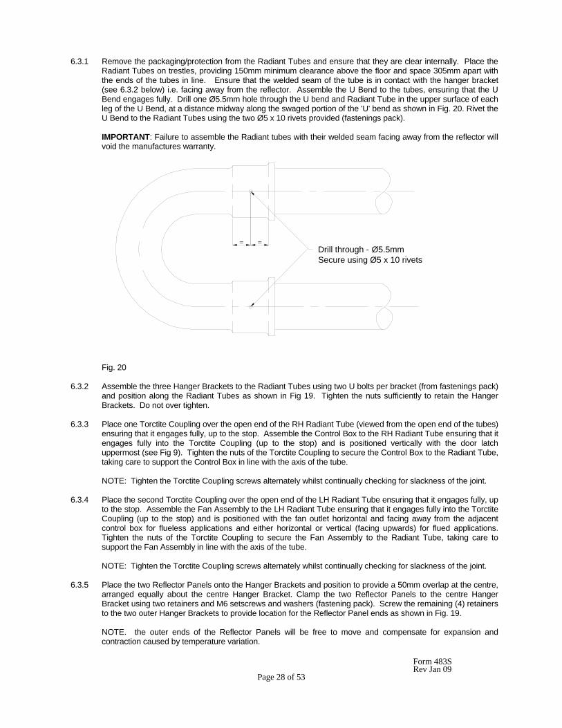
6.3.1 Remove the packaging/protection from the Radiant Tubes and ensure that they are clear internally. Place the Radiant Tubes on trestles, providing 150mm minimum clearance above the floor and space 305mm apart with the ends of the tubes in line. Ensure that the welded seam of the tube is in contact with the hanger bracket (see 6.3.2 below) i.e. facing away from the reflector. Assemble the U Bend to the tubes, ensuring that the U Bend engages fully. Drill one Ø5.5mm hole through the U bend and Radiant Tube in the upper surface of each leg of the U Bend, at a distance midway along the swaged portion of the 'U' bend as shown in Fig. 20. Rivet the U Bend to the Radiant Tubes using the two Ø5 x 10 rivets provided (fastenings pack).
IMPORTANT: Failure to assemble the Radiant tubes with their welded seam facing away from the reflector will void the manufactures warranty.
Fig. 20 6.3.2 Assemble the three Hanger Brackets to the Radiant Tubes using two U bolts per bracket (from fastenings pack)
and position along the Radiant Tubes as shown in Fig 19. Tighten the nuts sufficiently to retain the Hanger Brackets. Do not over tighten.
6.3.3 Place one Torctite Coupling over the open end of the RH Radiant Tube (viewed from the open end of the tubes)
ensuring that it engages fully, up to the stop. Assemble the Control Box to the RH Radiant Tube ensuring that it engages fully into the Torctite Coupling (up to the stop) and is positioned vertically with the door latch uppermost (see Fig 9). Tighten the nuts of the Torctite Coupling to secure the Control Box to the Radiant Tube, taking care to support the Control Box in line with the axis of the tube.
NOTE: Tighten the Torctite Coupling screws alternately whilst continually checking for slackness of the joint.
6.3.4 Place the second Torctite Coupling over the open end of the LH Radiant Tube ensuring that it engages fully, up
to the stop. Assemble the Fan Assembly to the LH Radiant Tube ensuring that it engages fully into the Torctite Coupling (up to the stop) and is positioned with the fan outlet horizontal and facing away from the adjacent control box for flueless applications and either horizontal or vertical (facing upwards) for flued applications. Tighten the nuts of the Torctite Coupling to secure the Fan Assembly to the Radiant Tube, taking care to support the Fan Assembly in line with the axis of the tube.
NOTE: Tighten the Torctite Coupling screws alternately whilst continually checking for slackness of the joint.
6.3.5 Place the two Reflector Panels onto the Hanger Brackets and position to provide a 50mm overlap at the centre,
arranged equally about the centre Hanger Bracket. Clamp the two Reflector Panels to the centre Hanger Bracket using two retainers and M6 setscrews and washers (fastening pack). Screw the remaining (4) retainers to the two outer Hanger Brackets to provide location for the Reflector Panel ends as shown in Fig. 19.
NOTE. the outer ends of the Reflector Panels will be free to move and compensate for expansion and contraction caused by temperature variation.
= = Drill through - Ø5.5mm Secure using Ø5 x 10 rivets
Form 483S Rev Jan 09 Page 29 of 53
6.3.6 Position the Reflector End Panel (notched) over the Radiant Tubes and into the end of the Reflector Panel with the End Panel flange flush with the end of the Reflector. Secure the Reflector End Panel to the Reflector Panel by use of 6 - U type speed clips provided (fastenings pack); 2 clips per facet of Reflector Panel, as shown in Fig. 19.
Repeat the procedure to attach the Reflector End Panel (plain) to the opposite end of the Reflector. 6.3.7 The appliance should now be raised and suspended from previously fixed chains or drop rods as detailed in
section 5.1, at suspension points indicated in Fig. 19. Rope or webbing slings should be used when lifting from above. If using a forklift to position the appliance, ensure that the appliance is balanced on the forks prior to lifting.
6.3.8 If combustion air is to be ducted to the appliance, attach a length of flexible ducting to the Air Inlet Adaptor of the Control Box by use of a suitable hoseclip. Attach the inlet end of the hose to any fixed ducting, also by use of a suitable hoseclip, allowing for adequate movement of the appliance. 6.3.9 Connect the gas supply in accordance with Section 5.2 - Gas supply, of these installation instructions. 6.3.10 Using twin core and earth flexible supply cable as specified in Section 5.3.2, suitable for 230V~50Hz 125W
supply, connect the 3 pin electrical socket provided (fastening pack) as follows:- Brown (Red) - to terminal marked L Blue (Black) - to terminal marked N Green/Yellow - to terminal marked 7 External fuse rating required - 3A See Section 5.3 for electricity supply requirements.
NOTE: It is important for the correct function of the appliance for the polarity of the electrical supply to be correct.
Form 483S Rev Jan 09 Page 30 of 53
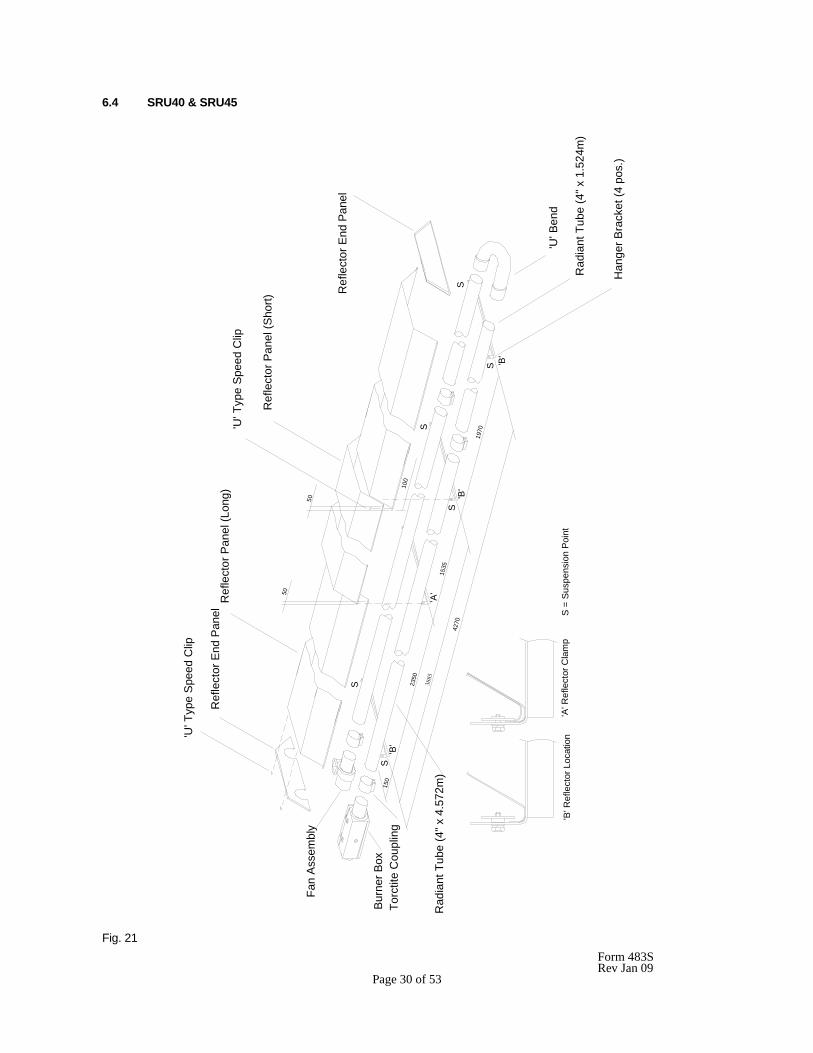
6.4 SRU40 & SRU45
Fig. 21
1535
3885
100
50
Ref
lect
or P
anel
(Sho
rt)
'U' T
ype
Spee
d C
lip
Rad
iant
Tub
e (4
" x 4
.572
m)
Rad
iant
Tub
e (4
" x 1
.524
m)
Han
ger B
rack
et (4
pos
.)
'B' R
efle
ctor
Loc
atio
n'A
' Ref
lect
or C
lam
pS
= S
uspe
nsio
n Po
int
Ref
lect
or E
nd P
anel
'U' T
ype
Spe
ed C
lip
Torc
tite
Cou
plin
gB
urne
r Box
Fan
Ass
embl
y
S15
0'B
'
4270
'B'
2350
S
50
1970
'B'
S
S
Ref
lect
or P
anel
(Lon
g)
'U' B
end
Ref
lect
or E
nd P
anel
'A'
S
S
Form 483S Rev Jan 09 Page 31 of 53
6.4.1 Remove the packaging/protection from the Radiant Tubes (2 long tubes and 2 short tubes) and ensure that
they are clear internally. Join one long tube and one short tube together using a Torctite Coupling. Ensure that the tubes engage fully into the Torctite Coupling (up to the stop) and that the welded seam of the tubes is in line from one tube to the other and that the Torctite Coupling clamp is positioned adjacent to the weld seam. Tighten the nuts of the Torctite Coupling to secure it to the tubes taking care to support the tubes to maintain the axis of the tube in a straight line. Repeat the procedure above to join the remaining long and short tubes. Place the Radiant Tube assemblies on tressels providing 150mm minimum clearance above the floor with the Torctite Coupling clamp underneath and the weld seam of the tubes in contact with the hanger bracket (see 6.4.3 below) i.e. facing away from the reflector. Space the tube assemblies 305mm apart with the ends of the short tubes (and Torctite Couplings) in line.
NOTE: Tighten the Torctite Coupling screws alternately whilst continually checking for slackness of the joint.
IMPORTANT: Failure to assemble the Radiant tubes with their welded seam facing away from the reflector will void the manufactures warranty.
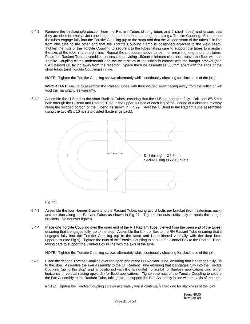
6.4.2 Assemble the U Bend to the short Radiant Tubes, ensuring that the U Bend engages fully. Drill one Ø5.5mm
hole through the U Bend and Radiant Tube in the upper surface of each leg of the U bend at a distance midway along the swaged portion of the U bend as shown in Fig 22. Rivet the U Bend to the Radiant Tube assemblies using the two Ø5 x 10 rivets provided (fastenings pack).
Fig. 22 6.4.3 Assemble the four Hanger Brackets to the Radiant Tubes using two U bolts per bracket (from fastenings pack)
and position along the Radiant Tubes as shown in Fig 21. Tighten the nuts sufficiently to retain the hanger brackets. Do not over tighten.
6.4.4 Place one Torctite Coupling over the open end of the RH Radiant Tube (viewed from the open end of the tubes)
ensuring that it engages fully, up to the stop. Assemble the Control Box to the RH Radiant Tube ensuring that it engages fully into the Torctite Coupling (up to the stop) and is positioned vertically with the door latch uppermost (see Fig 9). Tighten the nuts of the Torctite Coupling to secure the Control Box to the Radiant Tube, taking care to support the Control Box in line with the axis of the tube.
NOTE: Tighten the Torctite Coupling screws alternately whilst continually checking for slackness of the joint.
6.4.5 Place the second Torctite Coupling over the open end of the LH Radiant Tube, ensuring that it engages fully, up
to the stop. Assemble the Fan Assembly to the LH Radiant Tube ensuring that it engages fully into the Torctite Coupling (up to the stop) and is positioned with the fan outlet horizontal for flueless applications and either horizontal or vertical (facing upwards) for flued applications. Tighten the nuts of the Torctite Coupling to secure the Fan Assembly to the Radiant Tube, taking care to support the Fan Assembly in line with the axis of the tube.
NOTE: Tighten the Torctite Coupling screws alternately whilst continually checking for slackness of the joint.
= = Drill through - Ø5.5mm Secure using Ø5 x 10 rivets
Form 483S Rev Jan 09 Page 32 of 53
6.4.6 Place the two long Reflector Panels onto the Hanger Brackets and position as shown in Fig 18. Place the short Reflector Panel over the two long Reflector Panels to provide a 50mm overlap at each end. Clamp the long and short Reflector Panels (Control Box end) to the Hanger Bracket at which they overlap, using two retainers and M6 setscrews and washers (fastenings pack). Secure the other end of the short Reflector Panel to the second long Reflector Panel using two U type speed clips (from fastenings pack) as shown in Fig 21. Screw the remaining (6) retainers to each of the other Hanging Brackets to provide location for the Reflector Panels as shown in Fig 21.
Note: the Reflector Panels, not clamped where they overlap, will be free to move and compensate for expansion and contraction caused by temperature variation. 6.4.7 Position the Reflector End Panel (notched) over the Radiant Tubes and into the end of the Reflector Panel with
the End Panel flange flush with the end of the Reflector. Secure the Reflector End Panel to the Reflector Panel by use of 6-U type speed clips provided (fastenings pack); 2 clips per facet of Reflector Panel, as shown in Fig. 21.
Repeat the procedure to attach the Reflector End Panel (plain) to the opposite end of the Reflector. 6.4.8 The appliance should now be raised and suspended from previously fixed chains or drop rods as detailed in
Section 5.1, at suspension points indicated in Fig. 21. Rope or webbing slings should be used when lifting from above. If using a forklift to position the appliance, ensure that the appliance is balanced on the forks prior to lifting.
6.4.9 If combustion air is to be ducted to the appliance, attach a length a flexible ducting to the Air Inlet Adaptor of the Control Box by use of a suitable hoseclip. Attach the inlet end of the hose to any fixed ducting, also by use of a suitable hoseclip, allowing for adequate movement of the appliance. 6.4.10 Connect the gas supply in accordance with Section 5.2 - Gas Supply, of these installation instructions. 6.4.11 Using twin core and earth flexible supply cable as specified in Section 5.3.2, suitable for 230V~50Hz 125W
supply, connect the 3 pin electrical socket provided (fastening pack) as follows:- Brown (Red) - to terminal marked L Blue (Black) - to terminal marked N Green/Yellow - to terminal marked 7 External fuse rating required - 3A See Section 5.3 for electricity supply requirements.
NOTE: It is important for the correct function of the appliance for the polarity of the electrical supply to be correct.
Form 483S Rev Jan 09 Page 33 of 53
6.5 SRL09/12/15
Fig. 23
S
'B'
Torc
tite
Cou
plin
g
SS
2930
4272
1342
150
Fan
Ass
embl
y
'U' T
ype
Spe
ed C
lip
Ref
lect
or E
nd P
anel
Ref
lect
or E
nd P
anel
Ref
lect
or P
anel
(Sho
rt)
Ref
lect
or P
anel
(Lon
g)
50
S =
Sus
pens
ion
Poi
nt'B
' Ref
lect
or L
ocat
ion
'A' R
efle
ctor
Cla
mp
Han
ger B
rack
et (3
pos
.)
Rad
iant
Tub
e (3
" x 4
.572
m)
Burn
er B
ox
Torc
tite
Cou
plin
g
'B'
S'A
'
Form 483S Rev Jan 09 Page 34 of 53
6.5.1 Remove the packaging/protection from the Radiant Tube and ensure it is clear internally. The appliance should be assembled prior to being suspended and due consideration must be given to the means by which the appliance is to be safely raised into position.
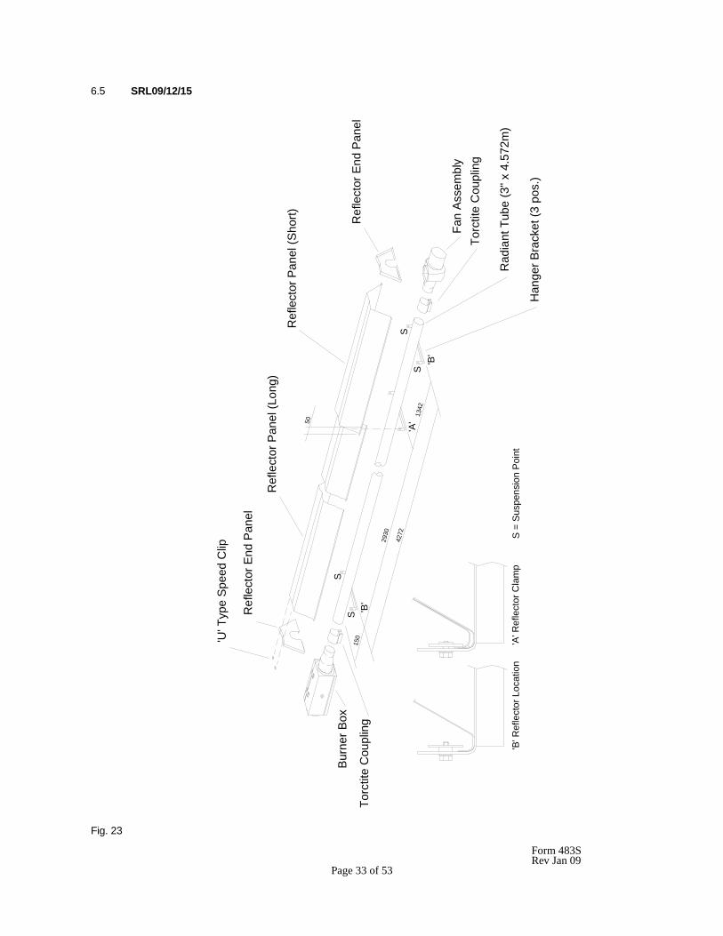
6.5.2 Place the Radiant Tube on trestles, providing 150mm minimum clearance above the floor and assemble the
three Hanger Brackets to the Radiant tube using one U bolt per bracket (fastening pack) and position along the Radiant Tubes as shown in Fig. 23. Ensure that the welded seam of the tube is in contact with the Hanger Bracket, i.e. facing away from the reflector. Tighten the nuts sufficiently to retain the Hanger Brackets. Do not overtighten.
IMPORTANT: Failure to assemble the Radiant Tube with its welded seam facing away from the reflector will
void the manufacturers warranty. 6.5.3 Place a Torctite Coupling over one end of the Radiant Tube ensuring that it engages fully up to the stop.
Assemble the Control Box to the Radiant Tube ensuring that it engages fully into the Torctite Coupling (up to the stop) and is positioned vertically with the door latch uppermost (see Fig. 10). Tighten the nuts of the Torctite Coupling to secure the Control Box to the Radiant Tube, taking care to support the Control Box in line with the axis of the tube.
NOTE: Tighten the Torctite Coupling screws alternately whilst continually checking for slackness of the joint. 6.5.4 Place a second Torctite Coupling over the open end of the Radiant Tube ensuring that it engages fully, (up to
the stop). Assemble the Fan Assembly to the Radiant Tube ensuring that it engages fully into the Torctite Coupling (up to the stop) and is positioned with the fan outlet horizontal for flueless applications and either horizontal or vertical (facing upwards) for flued applications. Tighten the nuts of the Torctite Coupling to secure the Fan Assembly to the Radiant Tube, taking care to support the Fan Assembly in line with the axis of the tube.
NOTE: Tighten the Torctite Coupling screws alternately whilst continually checking for slackness of the joint. 6.5.5 Place the two Reflector Panels onto the Hanger Brackets and position to provide a 50mm overlap, arranged
equally about the inner Hanger Bracket (see Fig 23.). Clamp the two Reflector Panels to the inner Hanger Bracket using two Retainers and M6 setscrews and washers (fastening pack). Screw the remaining (4) Retainers to the two outer Hanger Brackets to provide location for the Reflector Panel ends as shown in Fig. 23.
NOTE: The outer ends of the Reflector Panels will be free to move and compensate for expansion and
contraction caused by temperature variation. 6.5.6 Position one Reflector End Panel over the Radiant Tube and into one end of the Reflector Panels, with the End
Panel flange flush with the end of the Reflector Panel. Secure the Reflector End Panel to the Reflector Panel by use of six 'U' type speed clips provided (fastening pack): 2 clips per facet of Reflector Panel, as shown in Fig 23.
Repeat the procedure to attach the second Reflector End Panel to the opposite end of the reflector. 6.5.7 The appliance should now be raised and suspended from previously fixed chains or drop rods as detailed in
Section 53.1., at suspension points indicated in Fig. 23. Rope or webbing slings should be used when lifting from above. If using a forklift to position the appliance, ensure that it is balanced on the forks prior to lifting.
6.5.8 If combustion air is to be ducted to the appliance attach a length of flexible ducting to the Air Inlet Adaptor of the
Control Box by the use of a suitable hoseclip. Attach the inlet end of the hose to any fixed ducting, also by use of a suitable hoseclip, allowing for adequate movement of the appliance.
6.5.9 Connect the gas supply in accordance with Section 5.2. - Gas Supply, of these installation instructions.
Form 483S Rev Jan 09 Page 35 of 53
6.5.10 Using a suitable cable connector and twin core and earth PVC covered flexible supply cable, (0.5 mm2 to National or Local standard specification) connect the fan leads to the 3 pin plug provided (fastenings pack) as follows:- Brown (red) - to terminal marked L Blue (Black) - to terminal marked N Green/Yellow - to terminal marked 7
Connect this 3 pin plug to the electrical socket (marked ) mounted in the side of the Control Box. Due consideration should be given to the required clearance from combustibles (see section 5.1.4) when routing the cable from Fan to Control Box.
6.5.11 Using twin core and earth flexible supply cable, as specified in Section 5.3.2 suitable for 230V~50Hz 125W supply, connect the 3 pin electrical socket provided (fastenings pack) as follows:-
Brown (Red) - to terminal marked L Blue (Black) - to terminal marked N Green/Yellow - to terminal marked 7 Connect this electrical socket to the 3 pin plug (marked 230V~50Hz) mounted in the side of the Control Box. External fuse rating required - 3A See Section 5.3 for electrical supply requirements. NOTE: it is important for the correct function of the appliance for the polarity of the electrical supply to
be correct.
Form 483S Rev Jan 09 Page 36 of 53
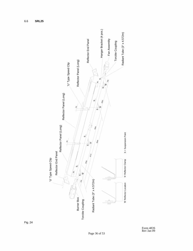
6.6 SRL25
Fig. 24
Ref
lect
or P
anel
(Lon
g)
'B'
50
150
2850
8845
Rad
iant
Tub
e (3
" x 4
.572
m)
SS
SS
'U' T
ype
Spee
d C
lip
80
80
Rad
iant
Tub
e (3
" x 4
.572
m)
S =
Sus
pens
ion
Poin
t'A
' Ref
lect
or C
lam
p'B
' Ref
lect
or L
ocat
ion
Han
ger B
rack
et (4
pos
.)
Ref
lect
or P
anel
(Lon
g)
Bur
ner B
ox
Torc
tite
Cou
plin
g'B
'S
150
4272
2930
S
Ref
lect
or E
nd P
anel
'U' T
ype
Spee
d C
lip
Torc
tite
Cou
plin
g
Ref
lect
or E
nd P
anel
Fan
Ass
embl
y
S
'A'
3065
'B'
S
Ref
lect
or P
anel
(Lon
g)50
Form 483S Rev Jan 09 Page 37 of 53
6.6.1 Remove the packaging/protection from the Radiant Tubes and ensure that they are clear internally. It is
recommended that the appliance is suspended in sections which are joined by the use of a Torctite Coupling once in position. Appliances may however, at the discretion of the installation engineer, be assembled (less Reflector Panels) prior to being suspended, in which case due consideration must be given to the means by which the appliance is to be safely raised into position.
6.6.2 Place the Radiant Tubes on trestles, providing 150mm minimum clearance above the floor and assemble the
four Hanger Brackets to the Radiant Tubes using one U bolt per bracket (from fastenings pack) and position along the Radiant Tubes as shown in Fig. 24. Ensure that the welded seam of the tubes is in contact with the Hanger Bracket i.e. facing away from the reflector. Tighten the nuts sufficiently to retain the Hanger Brackets. Do not overtighten.
IMPORTANT: Failure to assemble the Radiant Tubes with their welded seam facing away from the reflector will void the manufactures warranty.
6.6.3 Place one Torctite Coupling over the end of the relevant Radiant Tube ensuring that it engages fully up to the
stop. Assemble the Control Box to the Radiant Tube ensuring that it engages fully into the Torctite Coupling (up to the stop) and is positioned vertically with the door latch uppermost (see fig.10). Tighten the nuts of the Torctite Coupling to secure the Control Box to the Radiant Tube, taking care to support the Control Box in line with the axis of the tube.
NOTE: Tighten the Torctite Coupling screws alternately whilst continually checking for slackness of the joint.
6.6.4 Place a second Torctite Coupling over the end of the remaining Radiant Tube ensuring that it engages fully, up
to the stop. Assemble the Fan Assembly to the Radiant Tube ensuring that it engages fully into the Torctite Coupling (up to the stop) and is positioned with the fan outlet horizontal for flueless applications and either horizontal or vertical (facing upwards) for flues applications. Tighten the nuts of the Torctite Coupling to secure the Fan Assembly to the Radiant Tube, taking care to support the Fan Assembly in line with the axis of the tube.
NOTE: Tighten the Torctite Coupling screws alternately whilst continually checking for slackness of the joint.
6.6.5 The two sections of the appliance should now be raised and suspended from previously fixed chains or drop
rods as detailed in Section 5.1, at suspension points indicated in Fig. 24. Rope or webbing should be used when lifting from above. If using a forklift to position the appliance sections, ensure that they are balanced on the forks prior to lifting.
6.6.6 Place the third Torctite Coupling over the open end of one Radiant Tube ensuring that it engages fully, up to the
stop. Assemble the second Radiant Tube into the Torctite Coupling ensuring that it engages fully, up to the stop, with the Hanger Brackets aligned with those of the first Radiant Tube section (see Fig. 24). Tighten the nuts of the Torctite Coupling to secure the two sections of Radiant Tube to one another, taking care to maintain the tubes in a straight line.
NOTE: Tighten the Torctite Coupling screws alternately whilst continually checking for slackness of the joint.
6.6.7 Place two of the Reflector Panels onto the Hanger Brackets and position their outer edges such that they
overhang the outer Hanger Bracket by 80mm (see Fig. 24). Place the third Reflector Panel over the two previously positioned Reflector Panels to provide a 50mm overlap at each end. Clamp the first and second Reflector Panels, where they overlap, to the second Hanger Bracket, (from Control Box) using two retainers and M6 setscrews and washers (fastenings pack). Secure the outer end of the centre Reflector Panel to the Reflector Panel at the Fan Assembly end of the appliance, using two 'U' type speed clips (from fastenings pack) as shown in Fig. 24. Screw the remaining (6) retainers to each of the other Hanger Brackets to provide location for the Reflector Panels as shown in Fig.21.
Note: the Reflector Panels, where located but not clamped, will be free to move and compensate for expansion and contraction caused by temperature variation. 6.6.8 Position one Reflector End Panel over the Radiant Tube and into one end of the Reflector Panels with the End
Panel flange flush with the end of the Reflector Panel. Secure the Reflector End Panel to the Reflector Panel by the use of six 'U'' type speed clips provided (fastenings pack); 2 clips per facet of Reflector Panel, as shown in Fig. 24.
Repeat the procedure to attach the second Reflector End Panel to the opposite end of the Reflector.
Form 483S Rev Jan 09 Page 38 of 53
6.6.9 If combustion air is to be ducted to the appliance, attach a length of flexible ducting to the Air Inlet Adaptor of the Control Box by use of a suitable hoseclip. Attach the inlet end of the hose to any fixed ducting, also by use of a suitable hoseclip, allowing for adequate movement of the appliance. 6.6.10 Connect the gas supply in accordance with Section 5.2 - Gas supply, of these installation instructions. 6.6.11 Using a suitable cable connector and twin core and earth PVC covered flexible supply cable, (0.5 mm2 to National or Local standard specification) connect the fan leads to the 3 pin plug provided (fastenings pack) as follows:- Brown (red) - to terminal marked L Blue (Black) - to terminal marked N Green/Yellow - to terminal marked 7 Connect this 3 pin plug to the electrical socket (marked ) mounted in the side of the Control Box. Due
consideration should be given to the required clearance from combustibles (see section 5.1.4) when routing the cable from Fan to Control Box.
6.6.12 Using twin core and earth flexible supply cable, as specified in Section 5.3.2, suitable for 230V~50Hz 125W
supply, connect the 3 pin electrical socket provided (fastenings pack) as follows:- Brown (red) - to terminal marked L Blue (Black) - to terminal marked N Green/Yellow - to terminal marked 7 Connect this electrical socket to the 3 pin plug (marked 230V~50Hz) mounted in the side of the Control Box. External fuse rating required - 3A See Section 5.3 for electrical supply requirements.
NOTE: It is important for the correct function of the appliance for the polarity of the electrical supply to be correct.
Form 483S Rev Jan 09 Page 39 of 53
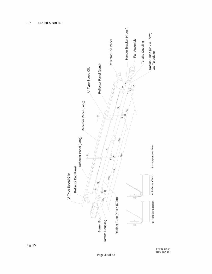
6.7 SRL30 & SRL35
Fig. 25
'U' T
ype
Spe
ed C
lip
80
80
Rad
iant
Tub
e (4
" x 4
.572
m)
c/w
Tur
bula
tor
Ref
lect
or E
nd P
anel
Han
ger B
rack
et (4
pos
.)
Ref
lect
or P
anel
(Lon
g)
S =
Sus
pens
ion
Poi
nt'A
' Ref
lect
or C
lam
p'B
' Ref
lect
or L
ocat
ion
Rad
iant
Tub
e (4
" x 4
.572
m)
Torc
tite
Cou
plin
g
Bur
ner B
ox15
0
4272
2930
'B'
SS
'U' T
ype
Spe
ed C
lip
Ref
lect
or E
nd P
anel
S88
45
'B'
2850
S'B
' 150
S
Fan
Ass
embl
y
Torc
tite
Cou
plin
g
S
'A'
S
3065
S
50
50
Ref
lect
or P
anel
(Lon
g)
Ref
lect
or P
anel
(Lon
g)
Form 483S Rev Jan 09 Page 40 of 53
6.7.1 Remove the packaging/protection from the Radiant Tubes and ensure that they are clear internally. It is
recommended that the appliance is suspended in sections which are joined by the use of a Torctite Coupling once in position. Appliances may however, at the discretion of the installation engineer be assembled (less reflector panels) prior to being suspended, in which case due consideration must be given to the means by which the appliance is to be safely raised into position.
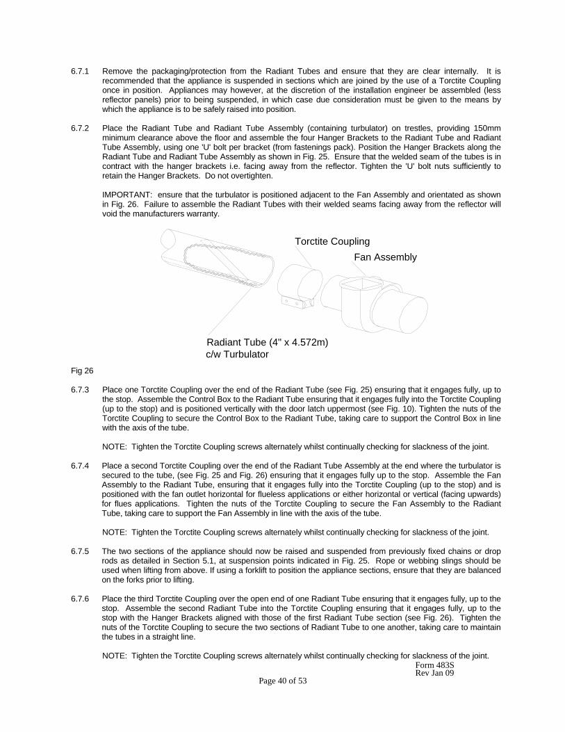
6.7.2 Place the Radiant Tube and Radiant Tube Assembly (containing turbulator) on trestles, providing 150mm
minimum clearance above the floor and assemble the four Hanger Brackets to the Radiant Tube and Radiant Tube Assembly, using one 'U' bolt per bracket (from fastenings pack). Position the Hanger Brackets along the Radiant Tube and Radiant Tube Assembly as shown in Fig. 25. Ensure that the welded seam of the tubes is in contract with the hanger brackets i.e. facing away from the reflector. Tighten the 'U' bolt nuts sufficiently to retain the Hanger Brackets. Do not overtighten.
IMPORTANT: ensure that the turbulator is positioned adjacent to the Fan Assembly and orientated as shown
in Fig. 26. Failure to assemble the Radiant Tubes with their welded seams facing away from the reflector will void the manufacturers warranty.
Fig 26 6.7.3 Place one Torctite Coupling over the end of the Radiant Tube (see Fig. 25) ensuring that it engages fully, up to
the stop. Assemble the Control Box to the Radiant Tube ensuring that it engages fully into the Torctite Coupling (up to the stop) and is positioned vertically with the door latch uppermost (see Fig. 10). Tighten the nuts of the Torctite Coupling to secure the Control Box to the Radiant Tube, taking care to support the Control Box in line with the axis of the tube.
NOTE: Tighten the Torctite Coupling screws alternately whilst continually checking for slackness of the joint.
6.7.4 Place a second Torctite Coupling over the end of the Radiant Tube Assembly at the end where the turbulator is
secured to the tube, (see Fig. 25 and Fig. 26) ensuring that it engages fully up to the stop. Assemble the Fan Assembly to the Radiant Tube, ensuring that it engages fully into the Torctite Coupling (up to the stop) and is positioned with the fan outlet horizontal for flueless applications or either horizontal or vertical (facing upwards) for flues applications. Tighten the nuts of the Torctite Coupling to secure the Fan Assembly to the Radiant Tube, taking care to support the Fan Assembly in line with the axis of the tube.
NOTE: Tighten the Torctite Coupling screws alternately whilst continually checking for slackness of the joint.
6.7.5 The two sections of the appliance should now be raised and suspended from previously fixed chains or drop
rods as detailed in Section 5.1, at suspension points indicated in Fig. 25. Rope or webbing slings should be used when lifting from above. If using a forklift to position the appliance sections, ensure that they are balanced on the forks prior to lifting.
6.7.6 Place the third Torctite Coupling over the open end of one Radiant Tube ensuring that it engages fully, up to the
stop. Assemble the second Radiant Tube into the Torctite Coupling ensuring that it engages fully, up to the stop with the Hanger Brackets aligned with those of the first Radiant Tube section (see Fig. 26). Tighten the nuts of the Torctite Coupling to secure the two sections of Radiant Tube to one another, taking care to maintain the tubes in a straight line. NOTE: Tighten the Torctite Coupling screws alternately whilst continually checking for slackness of the joint.
Radiant Tube (4" x 4.572m)c/w Turbulator
Fan AssemblyTorctite Coupling
Form 483S Rev Jan 09 Page 41 of 53
6.7.7 Place two of the Reflector Panels onto the Hanger Brackets and position their outer edges such that they overhang the outer Hanger Brackets by 80mm (see Fig. 25). Place the third Reflector Panel over the two previously positioned Reflector Panels to provide a 50mm overlap at each end. Clamp the first and second Reflector Panels, where they overlap, to the second Hanger Bracket (from Control Box end) using two retainers and M6 setscrews and washers (fastenings pack). Secure the outer end of the centre Reflector Panel to the Reflector Panel at the Fan Assembly end of the appliance using two U type speed clips (from fastenings pack) as shown in Fig. 25. Screw the remaining (6) retainers to each of the other Hanger Brackets to provide location for the Reflector Panels as shown in Fig. 25.
Note: the Reflector Panels, where located but not clamped will be free to move and compensate for expansion and contraction caused by temperature variation. 6.7.8 Position one Reflector End Panel over the Radiant Tube and into one end of the Reflector Panels with the End
Panel flange flush with the end of the Reflector Panel. Secure the Reflector End Panel to the Reflector Panels by use of six 'U' type speed clips provided (fastenings Pack); 2 clips per facet of Reflector Panel, as shown in Fig. 25.
Repeat the procedure to attach the second Reflector End Panel to the opposite end of the Reflector. 6.7.9 If combustion air is to be ducted to the appliance, attach a length of flexible ducting to the Air Inlet Adaptor of the Control Box by use of a suitable hoseclip. Attach the inlet end of the hose to any fixed ducting, also by use of a suitable hoseclip, allowing for adequate movement of the appliance. 6.7.10 Connect the gas supply in accordance with Section 5.2 - Gas supply, of these installation instructions. 6.7.11 Using a suitable cable connector and twin core and earth PVC covered flexible supply cable, (0.5 mm2 to National or Local standard specification) connect the fan leads to the 3 pin plug provided (fastenings pack) as follows:- Brown (red) - to terminal marked L Blue (Black) - to terminal marked N Green/Yellow - to terminal marked 7
Connect this 3 pin plug to the electrical socket (marked ) mounted in the side of the Control Box. Due consideration should be given to the required clearance from combustibles (see section 5.1.4) when routing the cable from Fan to Control Box.
6.7.12 Using twin core and earth flexible supply cable as specified in Section 5.3.2., suitable for 230V~50Hz 125W
supply, connect the 3 pin electrical socket provided (fastenings pack) as follows:- Brown (Red) - to terminal marked L Blue (Black) - to terminal marked N Green/Yellow - to terminal marked 7 Connect this electrical socket to the 3 pin plug (marked 230V~50Hz) mounted in the side of the Control Box. External fuse rating required - 3A See Section 5.3 for electrical supply requirement.
NOTE: It is important for the correct function of the appliance for the polarity of the electrical supply to be correct.
Form 483S Rev Jan 09 Page 42 of 53
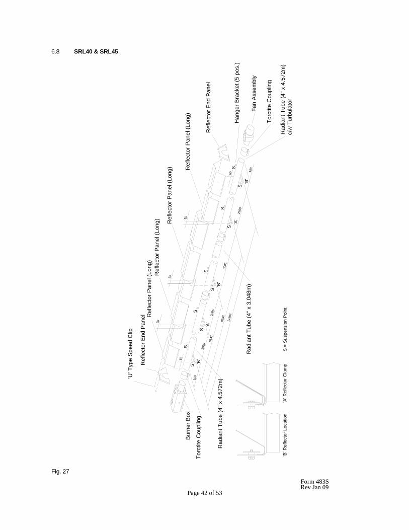
6.8 SRL40 & SRL45
Fig. 27
50R
efle
ctor
Pan
el (L
ong)
50
50
Ref
lect
or P
anel
(Lon
g) Ref
lect
or P
anel
(Lon
g)50
50S
S
'A'
2886
1189
2
Rad
iant
Tub
e (4
" x 4
.572
m)
Rad
iant
Tub
e (4
" x 3
.048
m)
'A' R
efle
ctor
Cla
mp
Rad
iant
Tub
e (4
" x 4
.572
m)
c/w
Tur
bula
tor
3086
'B' R
efle
ctor
Loc
atio
nS
= S
uspe
nsio
n Po
int
2960
8932
'A'
5847
SS
'B'
2960
SS
S
150
'B'
S
Torc
tite
Cou
plin
g
Han
ger B
rack
et (5
pos
.)
Fan
Ass
embl
y
Ref
lect
or E
nd P
anel
Bur
ner B
ox
Ref
lect
or P
anel
(Lon
g)R
efle
ctor
End
Pan
el
SS
'U' T
ype
Spe
ed C
lip
'B'
150
Torc
tite
Cou
plin
g
Form 483S Rev Jan 09 Page 43 of 53
6.8.1 Remove the packaging/protection from the Radiant Tubes and ensure that they are clear internally. It is
recommended that the appliance is suspended in sections which are joined by the use of Torctite Couplings once in position. Appliances may however, at the discretion of the installation engineer, be assembled (less reflector panels) prior to being suspended, in which case due consideration must be given to the means by which the appliance is to be safely raised into position.
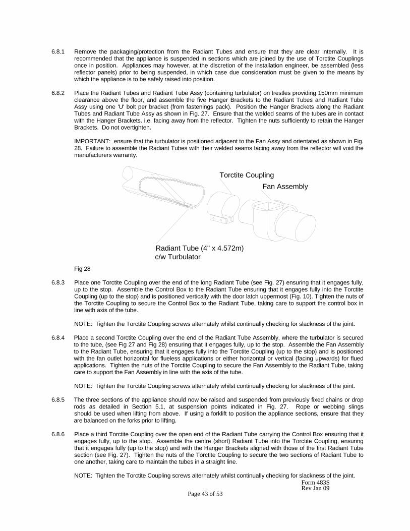
6.8.2 Place the Radiant Tubes and Radiant Tube Assy (containing turbulator) on trestles providing 150mm minimum
clearance above the floor, and assemble the five Hanger Brackets to the Radiant Tubes and Radiant Tube Assy using one 'U' bolt per bracket (from fastenings pack). Position the Hanger Brackets along the Radiant Tubes and Radiant Tube Assy as shown in Fig. 27. Ensure that the welded seams of the tubes are in contact with the Hanger Brackets. i.e. facing away from the reflector. Tighten the nuts sufficiently to retain the Hanger Brackets. Do not overtighten.
IMPORTANT: ensure that the turbulator is positioned adjacent to the Fan Assy and orientated as shown in Fig. 28. Failure to assemble the Radiant Tubes with their welded seams facing away from the reflector will void the manufacturers warranty.
Fig 28 6.8.3 Place one Torctite Coupling over the end of the long Radiant Tube (see Fig. 27) ensuring that it engages fully,
up to the stop. Assemble the Control Box to the Radiant Tube ensuring that it engages fully into the Torctite Coupling (up to the stop) and is positioned vertically with the door latch uppermost (Fig. 10). Tighten the nuts of the Torctite Coupling to secure the Control Box to the Radiant Tube, taking care to support the control box in line with axis of the tube.
NOTE: Tighten the Torctite Coupling screws alternately whilst continually checking for slackness of the joint.
6.8.4 Place a second Torctite Coupling over the end of the Radiant Tube Assembly, where the turbulator is secured
to the tube, (see Fig 27 and Fig 28) ensuring that it engages fully, up to the stop. Assemble the Fan Assembly to the Radiant Tube, ensuring that it engages fully into the Torctite Coupling (up to the stop) and is positioned with the fan outlet horizontal for flueless applications or either horizontal or vertical (facing upwards) for flued applications. Tighten the nuts of the Torctite Coupling to secure the Fan Assembly to the Radiant Tube, taking care to support the Fan Assembly in line with the axis of the tube.
NOTE: Tighten the Torctite Coupling screws alternately whilst continually checking for slackness of the joint.
6.8.5 The three sections of the appliance should now be raised and suspended from previously fixed chains or drop
rods as detailed in Section 5.1, at suspension points indicated in Fig. 27. Rope or webbing slings should be used when lifting from above. If using a forklift to position the appliance sections, ensure that they are balanced on the forks prior to lifting.
6.8.6 Place a third Torctite Coupling over the open end of the Radiant Tube carrying the Control Box ensuring that it
engages fully, up to the stop. Assemble the centre (short) Radiant Tube into the Torctite Coupling, ensuring that it engages fully (up to the stop) and with the Hanger Brackets aligned with those of the first Radiant Tube section (see Fig. 27). Tighten the nuts of the Torctite Coupling to secure the two sections of Radiant Tube to one another, taking care to maintain the tubes in a straight line.
NOTE: Tighten the Torctite Coupling screws alternately whilst continually checking for slackness of the joint.
Radiant Tube (4" x 4.572m)c/w Turbulator
Fan AssemblyTorctite Coupling
Form 483S Rev Jan 09 Page 44 of 53
6.8.7 Place the fourth Torctite Coupling over the open end of the Radiant Tube (and turbulator) Assembly carrying the Fan Assembly ensuring that it engages fully, up to the stop. Assemble the previously assembled section of Radiant Tubes into the Torctite Coupling ensuring that it engages fully (up to the stop) and with all the appliance Hanger Brackets correctly aligned with each other (see Fig. 27). Tighten the nuts of the Torctite Coupling to secure the two sections of Radiant Tube to one another, taking care to maintain the tubes in a straight line.
NOTE: Tighten the Torctite Coupling screws alternately whilst continually checking for slackness of the joint.
6.8.8 Place one Reflector Panel onto the two Hanger Brackets adjacent to the Control Box and a second Reflector
Panel onto the two Hanger Brackets adjacent to the Fan Assembly. Position the Reflector Panels such that their outer edges overhang the Hanger Brackets by 50mm (see Fig. 27). Place the remaining two Reflector Panels over the two outer Reflector Panels, ensuring that the centre overlap is as shown in Fig. 24, thus providing a 50mm overlap at each joint. Clamp the first and second Reflector Panels, where they overlap, to the second Hanger Bracket (from Control Box end) using two retainers and M6 setscrews and washers (fastenings pack). Clamp also, the third and fourth Reflector Panels where they overlap, to the fourth Hanger Bracket (from Control Box end) end using two retainers and M6 setscrews and washers (fastenings pack). Secure the two Reflector Panels that overlap adjacent to the centre Hanger Bracket, to each other using two 'U' type speed clips (fastenings pack) as shown in Fig. 27. Screw the remaining (6) retainers to each of the other Hanger Brackets to provide location for the Reflector Panels.
Note: the Reflector Panels, where located but not clamped, will be free to move and compensate for expansion and contraction caused by temperature variation. 6.8.9 Position one Reflector End Panel over the Radiant Tube and into one end of the Reflector Panels, with the End
Panel flange flush with the end of the Reflector Panel. Secure the Reflector End Panel to the Reflector Panel by use of six 'U' type speed clips provided (fastenings pack); 2 clips per facet of Reflector Panel, as shown in Fig. 27.
Repeat the procedure to attach the second Reflector End Panel to the opposite end of the Reflector. 6.8.10 If combustion air is to be ducted to the appliance attach a length of flexible ducting to the Air Inlet Adaptor of the Control Box by use of a suitable hoseclip. Attach the inlet end of the hose to any fixed ducting, also by use of a suitable hoseclip, allowing for adequate movement of the appliance. 6.8.11 Connect the gas supply in accordance with Section 5.2. - Gas supply, of these Installation Instructions. 6.8.12 Using twin core and earth flexible supply cable, as specified in Section 5.3.2, suitable for 230V~50Hz 125W
supply, connect the 3 pin electrical socket provided (fastenings pack) as follows:- Brown (Red) - to terminal marked L Blue (Black) - to terminal marked N Green/Yellow - to terminal marked 7 Connect this socket to the 3 pin plug (marked 230V~50Hz) mounted in the side of the Control Box. External fuse rating required - 3A See Section 5.3 for electrical supply requirements.
NOTE: It is important for the correct function of the appliance for the polarity of the electrical supply to be correct.
Form 483S Rev Jan 09 Page 45 of 53
7. COMMISSIONING
It is essential that all new pipework installations are purged and tested for soundness with a suitable leak detection fluid prior to attempting to ignite any appliance. This work should be carried out in accordance with National or Local regulations.
N.B. DO NOT TEST FOR SOUNDNESS BY USE OF NAKED FLAMES. 7.1 Ignition 7.1.1 Close and secure the Control Box door. The appliance will not operate unless the door is secured. 7.1.2 Turn on the gas supply to the appliance. 7.1.3 Set the system time clock and thermostat to demand heat. 7.1.4 Switch on the electricity supply to the appliance. The appliance red neon indicator will be illuminated, the
system fan will commence rotating and the air proving switch will sense an adequate air flow condition. The amber neon indicator will be illuminated.
7.1.5 After a purge period of 10 seconds minimum, the solenoid valves and ignition spark electrode will be energised simultaneously. 7.1.6 Upon successful ignition, the flame sensor will detect the flame, and the ignition spark electrode will be de-
energised. 7.1.7 Should the flame fail to permanently establish during the 12 second ignition period the solenoid valves and
ignition spark electrode will be de-energised, the amber neon indicator extinguished, the fan stop rotating, and the appliance ignition control go to "lockout" condition.
7.1.8 To repeat the ignition sequence it will be necessary to switch off the electricity supply to the appliance for a
period of 10 seconds to reset the ignition control. If a first reset is not successful, wait at least 15 seconds before repeating the procedure. After reset, an extended waiting time will occur.
7.1.9 If the burner fails to ignite following a second ignition sequence, switch off the electricity supply to the appliance, turn off the gas supply at the gas isolation valve and investigate the fault. 7.1.10 If gas failure occurs after successful ignition, the appliance ignition control will attempt one re-ignition before
going to "lockout" condition. 7.2 Shut Down 7.2.1 To shut down the appliance for short periods of time, switch off the electricity supply to the appliance. 7.2.2 To shut down the appliance for a period for time in excess of one week, switch off the electricity supply to the
appliance and turn off the gas supply at the gas isolation valve. Note: Concise operating instructions are contained on Instruction Label (4260440), which should be affixed, adjacent to a low level user control. 7.3 Checking Gas Pressures 7.3.1 Switch off the electricity supply to the appliance. 7.3.2 Connect a manometer to the test nipple protruding from the rear panel of the Control Box (adjacent to the Air
Inlet Adaptor) see Fig. 29. 7.3.3 Open the Control Box door after releasing the two toggle latches. 7.3.4 To check the gas supply pressure:-
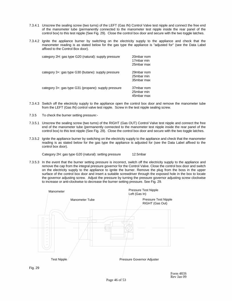
Form 483S Rev Jan 09 Page 46 of 53
7.3.4.1 Unscrew the sealing screw (two turns) of the LEFT (Gas IN) Control Valve test nipple and connect the free end of the manometer tube (permanently connected to the manometer test nipple inside the rear panel of the control box) to this test nipple (See Fig. 29). Close the control box door and secure with the two toggle latches.
7.3.4.2 Ignite the appliance burner by switching on the electricity supply to the appliance and check that the manometer reading is as stated below for the gas type the appliance is "adjusted for" (see the Data Label affixed to the Control Box door). category 2H: gas type G20 (natural): supply pressure 20mbar nom 17mbar min 25mbar max category 3+: gas type G30 (butane): supply pressure 29mbar nom 25mbar min 35mbar max category 3+: gas type G31 (propane): supply pressure 37mbar nom 25mbar min 45mbar max 7.3.4.3 Switch off the electricity supply to the appliance open the control box door and remove the manometer tube
from the LEFT (Gas IN) control valve test nipple. Screw in the test nipple sealing screw. 7.3.5 To check the burner setting pressure:- 7.3.5.1 Unscrew the sealing screw (two turns) of the RIGHT (Gas OUT) Control Valve test nipple and connect the free
end of the manometer tube (permanently connected to the manometer test nipple inside the rear panel of the control box) to this test nipple (See Fig. 29). Close the control box door and secure with the two toggle latches.
7.3.5.2 Ignite the appliance burner by switching on the electricity supply to the appliance and check that the manometer
reading is as stated below for the gas type the appliance is adjusted for (see the Data Label affixed to the control box door).
Category 2H: gas type G20 (natural): setting pressure 12.5mbar 7.3.5.3 In the event that the burner setting pressure is incorrect, switch off the electricity supply to the appliance and
remove the cap from the integral pressure governor for the Control Valve. Close the control box door and switch on the electricity supply to the appliance to ignite the burner. Remove the plug from the boss in the upper surface of the control box door and insert a suitable screwdriver through the exposed hole in the box to locate the governor adjusting screw. Adjust the pressure by turning the pressure governor adjusting screw clockwise to increase or anti-clockwise to decrease the burner setting pressure. See Fig. 29.
Fig. 29
Pressure Governor Adjuster
Pressure Test Nipple RIGHT (Gas Out)
Manometer Tube
Manometer
Test Nipple
Pressure Test Nipple Left (Gas In)
Form 483S Rev Jan 09 Page 47 of 53
7.3.5.4 Upon obtaining the correct burner setting pressure switch off the electricity supply to the appliance, remove the
screwdriver, replace the plug into the boss in the upper surface of the control box door and open the door. Remove the manometer tube from the RIGHT (Gas OUT) Control Valve test nipple and screw in the test nipple sealing screw. Close the control box door and secure it with the two toggle latches.
7.4 Flame Supervision 7.4.1 To check the operation of the flame supervision equipment, run the appliance normally, turn off the gas supply
at the gas isolation valve and observe that the amber neon indicator remains illuminated. 7.4.2 After a purge period of 10 seconds (minimum) the solenoid valves and the ignition spark electrode will be re-
energised and with the gas still turned off, the ignition control will go to "lockout" condition after a further 12 seconds (maximum). Amber neon indicator extinguished.
7.4.3 Switch off the electricity supply to the appliance for a period of 10 seconds before attempting to re-ignite the
burner. (see section 7.1.10). 7.5 Air Proving Switch 7.5.1 With the appliance running normally, disconnect the 3 pin electrical plug on the fan leads from the electrical
socket (marked ) mounted in the side of the Control Box. The burner should extinguish within 3 seconds. 7.5.2 Leave the Fan disconnected for 30 seconds to ensure that there is no attempt at re-ignition. 7.5.3 Switch off the electricity supply to the appliance and re-connect the electrical plug on the fan leads to the socket
(marked ) mounted in the side of the Control Box. 8. SERVICING
It is essential that at least once a year, preferably before the heating season, a qualified person service the appliance. In exceptionally dirty conditions, such as may occur in a foundry, more frequent servicing may be desirable.
IMPORTANT:- 1. Do not rest anything, especially ladders, against the appliance. 2. Gas and Electricity supplies must be isolated before commencing servicing work or replacement of components. 3. Unless instructed to the contrary, re-assemble components in reverse order. 4. Check all joints for gas soundness after carrying out any servicing of the appliance. 5. On completion of a service/fault finding task which has required the breaking and remaking of electrical corrections, the following checks, using a multimeter must be made. 5.1 Earth continuity check 5.2 Polarity check 5.3 Resistance to earth check 8.1 Fan 8.1.1 Disconnect the electrical plug on the fan leads from the socket (marked ) mounted in the side of the Control Box. 8.1.2 If a flued installation, disconnect the flue from the Fan. 8.1.3 Slacken the nuts of the Torctite Coupling securing the Fan Connector to the Radiant Tube and draw the Fan
Assembly off the Radiant Tube. 8.1.4 Inspect the main impeller and secondary cooling impeller and remove any dust by brushing with a soft brush.
Check that the impeller rotates freely and that there is no excessive play in the bearings. The bearings are pre-lubricated and require no attention.
Form 483S Rev Jan 09 Page 48 of 53
8.2 Control Box The control box can be removed from the appliance and serviced at ground level. 8.2.1 Disconnect the electrical supply socket from the 3 pin plug (marked 230V~50Hz) mounted in the side of the
Control Box, turn off the gas supply to the appliance at the gas isolation valve and disconnect the gas supply pipe from the control box, leaving the R - ½ nipple screwed into the Control Valve flanged elbow.
8.2.2 Slacken the nuts of the Torctite Coupling securing the Control Box Connector to the Radiant Tube and draw the
Control Box Assembly off the Radiant Tube. 8.2.3 Ignition Electrodes 8.2.3.1 Open the Control Box door after releasing the two toggle latches. 8.2.3.2 Disconnect the grey HT ignition/flame sensor lead and the green/yellow earth lead from the electrodes by gently
pulling the connectors, using pliers. 8.2.3.3 Unscrew the M6 x 16 setscrew securing the electrode carrier to the Control Box and remove the Electrode
Assembly. 8.2.3.4 Remove any foreign matter from the Electrode tips and check that the spark gap is 3.5mm. If the Electrode
rods are badly oxidised, replace the Electrodes (see section 7.2). 8.2.3.5 Upon re-assembly, ensure that the HT lead and earth lead connectors are securely attached to the Electrodes. 8.2.4 Burner 8.2.4.1 Unscrew, the two M4 x 25 setscrews from the Burner Bracket and remove the Burner Clamp. Unscrew the
Burner from the Injector Fitting and lift out of the Control Box. Clean by use of a stiff brush to remove any deposits.
8.2.4.2 Inspect the Injector and clean as necessary with a soft bristle brush. DO NOT DAMAGE THE INJECTOR ORIFICE BY USE OF SOLID OBJECTS. 8.2.4.3 To remove or replace the Injector, unscrew it from the Injector Fitting using a spanner, whilst retaining the
Injector Fitting with a second spanner. 8.2.5 Electrical Wiring 8.2.5.1 Check that all the electrical connections are sound and that the wiring is undamaged. Replace damaged wires
as necessary. 8.2.6 Air Inlet/Baffle Plate 8.2.6.1 Check that the air inlet holes in the Baffle Plate, which is clamped between the Control Box end panel and the
Air Inlet flange, are clear from obstructions. Check also, that the wire mesh panel of the Air Inlet is clean. Clean as necessary using a soft brush.
8.2.6.2 In the case of an appliance having a ducted air supply, it will be necessary to disconnect the flexible ducting from the Air Inlet by first releasing the hoseclip. 8.2.6.3 If it is necessary to remove the Air Inlet to adequately clean the Baffle Plate it will be necessary to replace the
gasket seal (see section 9.10 - Replacement Parts). 8.2.7 Door Seal 8.2.7.1 Check the condition of the seal around the Control Box door and replace as necessary (see section 9.10
Replacement Parts) IMPORTANT: The appliance will not function unless the seal around the control box door is sound and the
door secured with the two toggle latches.
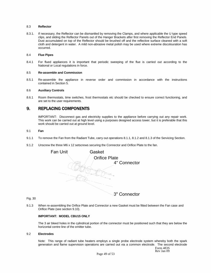
Form 483S Rev Jan 09 Page 49 of 53
8.3 Reflector 8.3.1. If necessary, the Reflector can be dismantled by removing the Clamps, and where applicable the U type speed
clips, and sliding the Reflector Panels out of the Hanger Brackets after first removing the Reflector End Panels. Dust accumulated on top of the Reflector should be brushed off and the reflective surface cleaned with a soft cloth and detergent in water. A mild non-abrasive metal polish may be used where extreme discolouration has occurred.
8.4 Flue Pipes 8.4.1 For flued appliances it is important that periodic sweeping of the flue is carried out according to the National or Local regulations in force. 8.5 Re-assemble and Commission 8.5.1 Re-assemble the appliance in reverse order and commission in accordance with the instructions contained in Section 5. 8.6 Auxiliary Controls 8.6.1 Room thermostats, time switches, frost thermostats etc should be checked to ensure correct functioning, and
are set to the user requirements. 9. REPLACING COMPONENTS
IMPORTANT: Disconnect gas and electricity supplies to the appliance before carrying out any repair work. This work can be carried out at high level using a purposes designed access tower, but it is preferable that this work should be carried out at ground level.
9.1 Fan 9.1.1 To remove the Fan from the Radiant Tube, carry out operations 8.1.1, 8.1.2 and 8.1.3 of the Servicing Section. 9.1.2 Unscrew the three M6 x 12 setscrews securing the Connector and Orifice Plate to the fan.
Fig. 30 9.1.3 When re-assembling the Orifice Plate and Connector a new Gasket must be fitted between the Fan case and
Orifice Plate (see section 9.10). IMPORTANT: MODEL CBU15 ONLY
The 3 air bleed holes in the cylindrical portion of the connector must be positioned such that they are below the horizontal centre line of the emitter tube.
9.2 Electrodes
Note: This range of radiant tube heaters employs a single probe electrode system whereby both the spark generation and flame supervision operations are carried out via a common electrode. The second electrode
4" ConnectorOrifice Plate
Form 483S Rev Jan 09 Page 50 of 53
provides the earth path for the ignition spark. The two electrodes are identical, therefore either lead (grey HT or green/yellow - earth) may be connected to either electrode.
9.2.1 Disconnect the grey HT ignition/flame sensor lead and the green/yellow earth lead from the electrodes by gently
pulling the connectors, using pliers. 9.2.2 Unscrew the M6 x 16 setscrew securing the Electrode Assembly to the Control Box end panel and remove the Electrode Assembly. 9.2.3 Unscrew the M3 setscrews securing the Electrodes to the Carrier and withdrawn the Electrodes. 9.2.4 After assembling replacement Electrodes to the Carrier, check that the spark gap is 3.5mm before inserting the
Electrode Assembly into the Control Box and securing to the Control Box end panel with the M6 x 16 setscrews.
9.3 Ignition Control (Honeywell S4565R1006) 9.3.1 Unscrew the two screws securing the cable clamp to the ignition control and remove the cable clamp. 9.3.2 Disconnect the 12 way Molex electrical connector and the grey HT ignition spark/flame sensor lead from the
Ignition Control. 9.3.3 Unscrew the M3 screw securing the Ignition Control to the Control Valve and lift out the Ignition Control. 9.4 Air Proving Switch 9.4.1 Remove the Air Tube Assembly from the Air Proving Switch pressure connection marked 'H' and from the Test
Nipple located in the centre of the Air Inlet Baffle Plate. 9.4.2 Unscrew the two No. 8 x 12 self tapping screws securing the Air Proving Switch to the floor of the Control box
and lift out with the electrical leads attached. 9.4.3 Disconnect the three electrical leads from the Air Proving Switch by gently pulling the connectors, using pliers. 9.4.4 Remove the restrictor from the Air Switch Pressure connection marked L. 9.4.5 When installing a replacement Air Pressure Switch, take care to connect the electrical leads in accordance with
the wiring diagram shown in Section 5.3.3 - Fig. 13 and replace the restrictor on the pressure connection marked L. The appliance will not function unless this restrictor is in place.
9.5 Burner Assembly 9.5.1 To replace the Burner, unscrew the two M4 x 25 setscrews from the Burner Bracket and remove the Burner Clamp. Unscrew the Burner from the Injector Fitting and lift out of the Control Box. 9.6 Injector 9.6.1 Remove the Burner as described at 7.5 above. Unscrew the Injector from the Injector Fitting, using a spanner, whilst retaining the Injector Fitting with a second spanner. 9.7 Pre-Injector 9.7.1 For models SRU/SRL-30,35,40,45, appliance category 2E+ only, there is a Pre-injector fitted into the Injector
Fitting. In the unlikely event that it should be necessary to replace this Pre-injector, first unscrew the Injector Fitting from the straight flange attached to the Control Valve outlet port, and unscrew the pre-injector from the Injector Fitting using a spanner, whilst retaining the Injector Fitting with a second spanner or by holding in a vice.
Form 483S Rev Jan 09 Page 51 of 53
9.8 Twin solenoid Control Valve 9.8.1 Remove the Ignition Control (see section 9.3) and the Burner (see section 9.5) and disconnect the gas supply
pipe from the Control Box, leaving the R - ½ nipple screwed into the Control Valve elbow flange. Unscrew the two M4 setscrews securing the Valve Bracket to the floor of the Control Box and lift out the Control Valve Assembly.
9.8.2 Unscrew the four M4 screws securing the elbow flange to the Control Valve inlet port and remove the elbow
flange and R - ½ nipple, complete. 9.8.3 Unscrew the four M4 screws securing the straight flange to the Control Valve outlet port and remove the
straight flange and injector fitting, complete. 9.8.4 Unscrew the two M4 screws securing the Valve Bracket to the Control Valve mounting boss and remove the
Valve Bracket. 9.8.5 After replacing the Control Valve, check the gas pressures in accordance with Section 5.3 of this manual. IMPORTANT: TEST FOR GAS SOUNDNESS USING A SUITABLE LEAK DETECTION FLUID. 9.9 Neon Indicator 9.9.1 Disconnect the electrical leads from the Neon Indicators by gently pulling the connectors, using pliers. 9.9.2 Press the Neon Indicator out through the mounting hole in the floor of the Control Box. Remove the spring
fixing washer from the Control Box. 9.9.3 When replacing a Neon Indicator, pass it through the mounting hole in the floor of the Control Box and press
the spring fixing washer over the body of the Neon Indicator and up against the Control Box floor panel to secure the Neon Indicator. Connect the electrical leads in accordance with the wiring diagram shown in Section 5.3.3 Fig. 13.
9.10 Replacement Parts List The following is a list of replacement parts which may be required during the life of the appliance. Part Part Number Gasket 4260132 Electrode 4260368 Ignition Control 4262197 Control Valve 4262586 Fan 4262256 Air Proving Switch 4262278 Neon Indicator-Red 4262280 Neon Indicator-Amber 4262281 Sealing Strip (Control Box door) 4262409 10. CONVERSION INSTRUCTIONS 10.1 Conversion from cat. 2H (Natural Gas) to cat 3+ (LPG). 10.1.1 Remove the Injector from the Injector Fitting (see section 9.6) and replace it with the alternative Injector
supplied (fastenings pack). Check that the size reference marked on the Injector agrees with that listed in the Technical Data table (Section 1) for the appliance model in question.
10.1.2 Remove the pressure governor cap from the integral pressure governor of the Control Valve and screw the
adjuster clockwise up to the stop, to put the governor out of action. Replace the pressure governor cap. 10.1.3 Affix the gas adjustment label (3+ G30/G31, 29/37mbar) supplied (fastenings pack) onto the Data Label,
adjacent to the headings "Adjusted For" and "Setting Pressure", to cover the original gas adjustment label (2H, G20, 20mbar).
Form 483S Rev Jan 09 Page 52 of 53
10.1.4 Carry out checks in accordance with Section 7.3 of this manual to ensure correct supply pressure relative to the gas type being used (G30 - Butane or G31 - Propane).
10.2 Conversion from cat 3+ (LPG) to cat 2H (Natural Gas) 10.2.1 Remove the Injector from the Injector Fitting (see Section 9.6) and replace it with the alternative Injector
supplied (fastenings pack). Check that the size reference marked on the Injector agrees with that listed in the Technical Data table (Section 1) for the appliance model in question.
10.2.2 Remove the pressure governor cap from the integral pressure governor of the Control Valve and unscrew the adjuster anti-clockwise 3 complete turns. 10.2.3 Affix the gas adjustment label (2H, G20, 20mbar) supplied (fastenings pack) onto the Data Label adjacent to the
headings, "Adjusted For" and "Setting Pressure" to cover the original gas adjustment label (3+, G30/G31, 29/37mbar).
10.2.4 Carry out checks in accordance with Section 7.3 of this manual to ensure correct supply pressure and setting pressure, relative to the gas type being used (G20 - Natural Gas). 11 OPERATING INSTRUCTIONS 11.1. Ensure that the Control Box door is closed and secured with the two toggle latches. The heater will not operate with the door open. 11.2 Turn on the gas supply to the appliance. 11.3 Set any time switches or thermostats to demand heat. 11.4 Switch on the electricity supply to the appliance. The red neon indicator and amber neon indicator will be
illuminated. 11.5 The burner should ignite within 20 seconds. Both red and amber neon indicators will remain illuminated. 11.6 Failure to ignite will result in the ignition controller going to "lockout" condition. The red neon indicator will
remain illuminated. The amber neon indicator will be extinguished. 11.7 If lockout occurs, switch off the electricity supply to the appliance, wait for 10 seconds before switching on the
electricity supply to the appliance to repeat the ignition sequence. 11.8 If the appliance fails to ignite after a second sequence switch off the electrical supply to the appliance and call
the service engineer. 11.9 If gas failure occurs after successful ignition the appliance will attempt one re-ignition before going to lockout condition. 11.10 To shut down the appliance for short periods of time, switch off the electricity supply to the appliance. 11.11 To shut down the appliance for longer periods of time, switch of the electricity supply to the appliance and turn
off the gas supply at the gas isolation valve.
Form 483S Rev Jan 09 Page 53 of 53
NOTES: GB IE (ES IT PT)