Embed Size (px)
Citation preview
1
CD 21/2015 (B)
BID FOR SUPPLY AND DELIVERY OF OVERHEAD POWERLINE EQUIPMENT
CENTLEC
2
BID FOR SUPPLY AND DELIVERY OF OVERHEAD POWERLINE EQUIPMENT FOR A PERIOD OF THREE (3) YEARS.
OVERHEAD POWERLINE EQUIPMENT: TECHNICAL SPECIFICATION AND
PRICE SCHEDULE
1. Introduction
CENTLEC (SOC) (Ltd) invites BIDS for supply and delivery of Overhead Powerline Equipment as
detailed in the specification below for a period of three (3) years. 2. Minimum Submission Requirements – Any Omission Of The Listed Items Would Render
An Automatic Disqualification
2.1 One (1) letter of references from previous companies where similar projects were successfully completed and signed by the duly authorized company representative.
2.2 Valid original tax clearance certificate.
2.3 Supply municipal services (Water, Sanitation, Rates and Electricity) bill(s), not owing more than 30 days; or valid clearance certificate. A valid lease Agreement with Current Bill of Account not owing more than thirty (30) days for municipal services that the lessee (Bidder) is responsible for. In the event that the Bidder utilized prepaid services (e.g. water or and electricity) a valid clearance certificate must be submitted. Bidders that are CENTLEC (SOC) Ltd customers are also expected to attach a valid clearance certificate.
3. Scope Of Work
This contract covers the manufacture and delivery of overhead powerline equipment as described in the specification and schedules. All equipment shall be suitable for use on the distribution systems of the Mangaung Metropolitan Municipality and CENTLEC the Regional Electrical Distributor
4. Special Conditions of the bid
4.1 Please note that CENTLEC reserves the right to appoint more than one bidder where
applicable.
4.2 Any work outside of the current scope of work but related to this Bid, identified by CENTLEC duly authorized persons can be quoted by the approved bidder.
4.3 The quotation can be considered by CENTLEC and a work instruction generated for the
quoted ad hoc work. 4.4 Any amendments to the legal and procedural content of this bid shall be addressed in the
SLA entered into by CENTLEC and successful bidder(s). 4.5 The successful bidder will be expected to enter into a Service Level Agreement with
CENTLEC.
3
5. TECHNICAL SPECIFICATION
5.1 GENERAL REMARKS
The electrical equipment covered by this enquiry must be suitable for a 50 Hz AC
network, which operates at the voltages specified for the various items.
The neutral point of the 400/231V network is solidly earthed. The star point on the 11 kV
system in Bloemfontein is earthed through a 600 A (10, 58 ohm) resistor. The
meteorological conditions for Bloemfontein are:
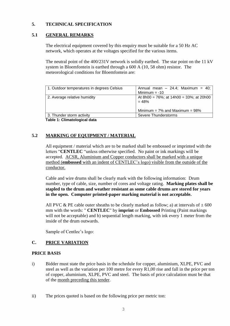
1. Outdoor temperatures in degrees Celsius Annual mean – 24.4; Maximum = 40;
Minimum = -10
2. Average relative humidity At 8h00 = 76%; at 14h00 = 33%; at 20h00 = 48% Minimum = 7% and Maximum = 98%
3. Thunder storm activity Severe Thunderstorms
Table 1: Climatological data
5.2 MARKING OF EQUIPMENT / MATERIAL
All equipment / material which are to be marked shall be embossed or imprinted with the
letters “CENTLEC “unless otherwise specified. No paint or ink markings will be
accepted. ACSR, Aluminium and Copper conductors shall be marked with a unique
method (embossed with an indent of CENTLEC’s logo) visible from the outside of the
conductor.
Cable and wire drums shall be clearly mark with the following information: Drum
number, type of cable, size, number of cores and voltage rating. Marking plates shall be
stapled to the drum and weather resistant as some cable drums are stored for years
in the open. Computer printed-paper marking material is not acceptable.
All PVC & PE cable outer sheaths to be clearly marked as follow; a) at intervals of ± 600
mm with the words: " CENTLEC" by imprint or Embossed Printing (Paint markings
will not be acceptable) and b) sequential length marking, with ink every 1 meter from the
inside of the drum outwards.
Sample of Centlec’s logo:
C. PRICE VARIATION
PRICE BASIS
i) Bidder must state the price basis in the schedule for copper, aluminium, XLPE, PVC and
steel as well as the variation per 100 metre for every R1,00 rise and fall in the price per ton
of copper, aluminium, XLPE, PVC and steel. The basis of price calculation must be that
of the month preceding this tender.
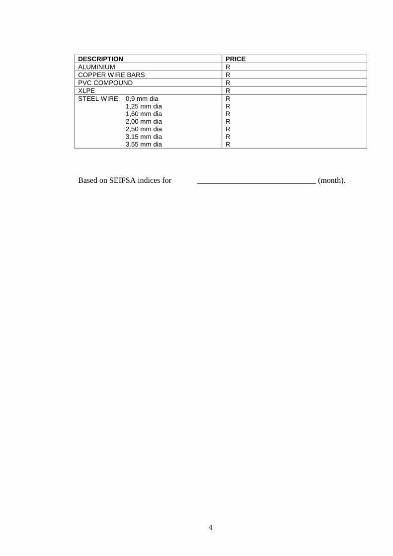
ii) The prices quoted is based on the following price per metric ton:
4
DESCRIPTION PRICE
ALUMINIUM R
COPPER WIRE BARS R
PVC COMPOUND R
XLPE R
STEEL WIRE: 0,9 mm dia 1,25 mm dia 1,60 mm dia 2,00 mm dia 2,50 mm dia 3.15 mm dia 3.55 mm dia
R R R R R R R
Based on SEIFSA indices for ______________________________ (month).
5
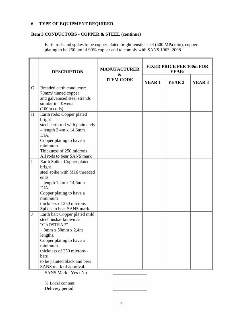
6 TYPE OF EQUIPMENT REQUIRED
Item 3 CONDUCTORS - COPPER & STEEL (continue)
Earth rods and spikes to be copper plated bright tensile steel (500 MPa min), copper
plating to be 250 um of 99% copper and to comply with SANS 1063: 2008.
DESCRIPTION
MANUFACTURER
&
ITEM CODE
FIXED PRICE PER 100m FOR
YEAR:
YEAR 1
YEAR 2
YEAR 3
G Breaded earth conductor:
70mm² tinned copper
and galvanised steel strands
similar to “Kwena”
(100m coils)
H Earth rods: Copper plated
bright
steel earth rod with plain ends
– length 2.4m x 14,6mm
DIA,
Copper plating to have a
minimum
Thickness of 250 microns
All rods to bear SANS mark
I Earth Spike: Copper plated
bright
steel spike with M16 threaded
ends
– length 1.2m x 14,6mm
DIA,
Copper plating to have a
minimum
thickness of 250 microns
Spikes to bear SANS mark.
J Earth bar: Copper plated mild
steel busbar known as
“CADSTRAP”
– 3mm x 50mm x 2,4m
lengths,
Copper plating to have a
minimum
thickness of 250 microns -
bars
to be painted black and bear
SANS mark of approval.
SANS Mark: Yes / No _______________
% Local content _______________
Delivery period _______________
6
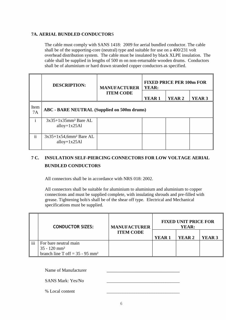
7A. AERIAL BUNDLED CONDUCTORS
The cable must comply with SANS 1418: 2009 for aerial bundled conductor. The cable
shall be of the supporting-core (neutral) type and suitable for use on a 400/231 volt
overhead distribution system. The cable must be insulated by black XLPE insulation. The
cable shall be supplied in lengths of 500 m on non-returnable wooden drums. Conductors
shall be of aluminium or hard drawn stranded copper conductors as specified.
DESCRIPTION:
MANUFACTURER
ITEM CODE
FIXED PRICE PER 100m FOR
YEAR:
YEAR 1
YEAR 2
YEAR 3
Item
7A
ABC - BARE NEUTRAL (Supplied on 500m drums)
i 3x35+1x35mm² Bare AL
alloy+1x25Al
ii 3x35+1x54,6mm² Bare AL
alloy+1x25Al
7 C. INSULATION SELF-PIERCING CONNECTORS FOR LOW VOLTAGE AERIAL
BUNDLED CONDUCTORS
All connectors shall be in accordance with NRS 018: 2002.
All connectors shall be suitable for aluminium to aluminium and aluminium to copper
connections and must be supplied complete, with insulating shrouds and pre-filled with
grease. Tightening bolt/s shall be of the shear off type. Electrical and Mechanical
specifications must be supplied.
CONDUCTOR SIZES:
MANUFACTURER
ITEM CODE
FIXED UNIT PRICE FOR
YEAR:
YEAR 1
YEAR 2
YEAR 3
iii For bare neutral main _______________ ________
35 - 120 mm²
branch line T off = 35 - 95 mm²
Name of Manufacturer ________________________________
SANS Mark: Yes/No ________________________________
% Local content ________________________________
7
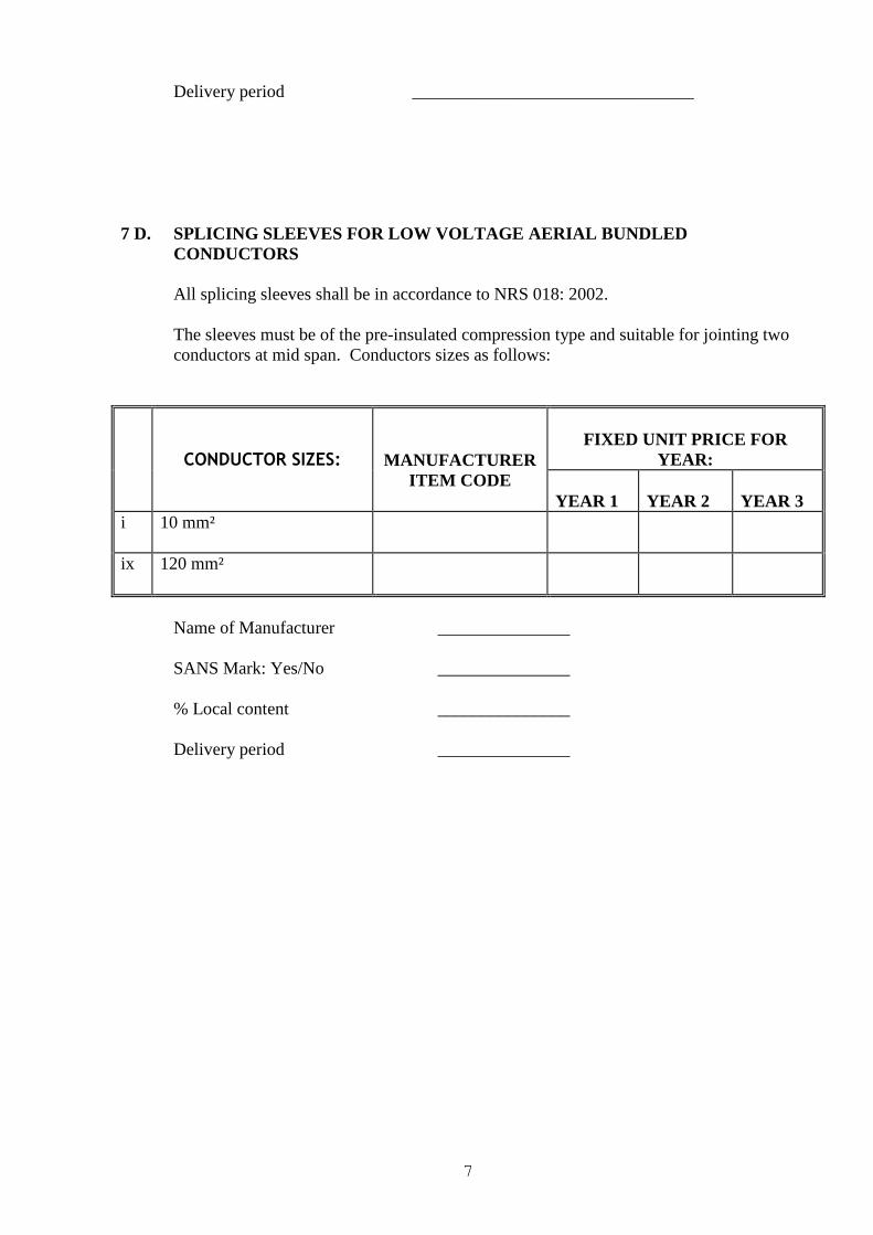
Delivery period ________________________________
7 D. SPLICING SLEEVES FOR LOW VOLTAGE AERIAL BUNDLED
CONDUCTORS
All splicing sleeves shall be in accordance to NRS 018: 2002.
The sleeves must be of the pre-insulated compression type and suitable for jointing two
conductors at mid span. Conductors sizes as follows:
CONDUCTOR SIZES:
MANUFACTURER
ITEM CODE
FIXED UNIT PRICE FOR
YEAR:
YEAR 1
YEAR 2
YEAR 3
i 10 mm²
ix 120 mm²
Name of Manufacturer _______________
SANS Mark: Yes/No _______________
% Local content _______________
Delivery period _______________
8
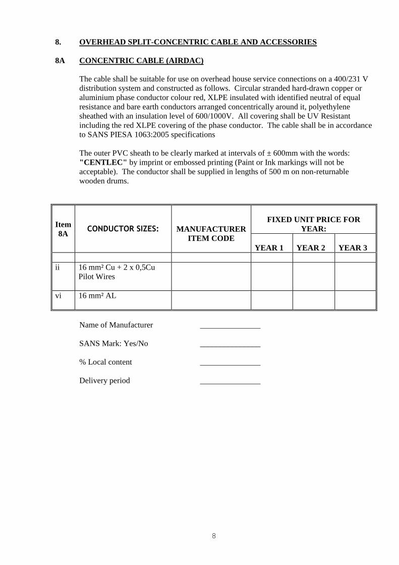
8. OVERHEAD SPLIT-CONCENTRIC CABLE AND ACCESSORIES
8A CONCENTRIC CABLE (AIRDAC)
The cable shall be suitable for use on overhead house service connections on a 400/231 V
distribution system and constructed as follows. Circular stranded hard-drawn copper or
aluminium phase conductor colour red, XLPE insulated with identified neutral of equal
resistance and bare earth conductors arranged concentrically around it, polyethylene
sheathed with an insulation level of 600/1000V. All covering shall be UV Resistant
including the red XLPE covering of the phase conductor. The cable shall be in accordance
to SANS PIESA 1063:2005 specifications
The outer PVC sheath to be clearly marked at intervals of ± 600mm with the words:
"CENTLEC" by imprint or embossed printing (Paint or Ink markings will not be
acceptable). The conductor shall be supplied in lengths of 500 m on non-returnable
wooden drums.
Item
8A
CONDUCTOR SIZES:
MANUFACTURER
ITEM CODE
FIXED UNIT PRICE FOR
YEAR:
YEAR 1
YEAR 2
YEAR 3
ii 16 mm² Cu + 2 x 0,5Cu
Pilot Wires
vi 16 mm² AL
Name of Manufacturer _______________
SANS Mark: Yes/No _______________
% Local content _______________
Delivery period _______________
9
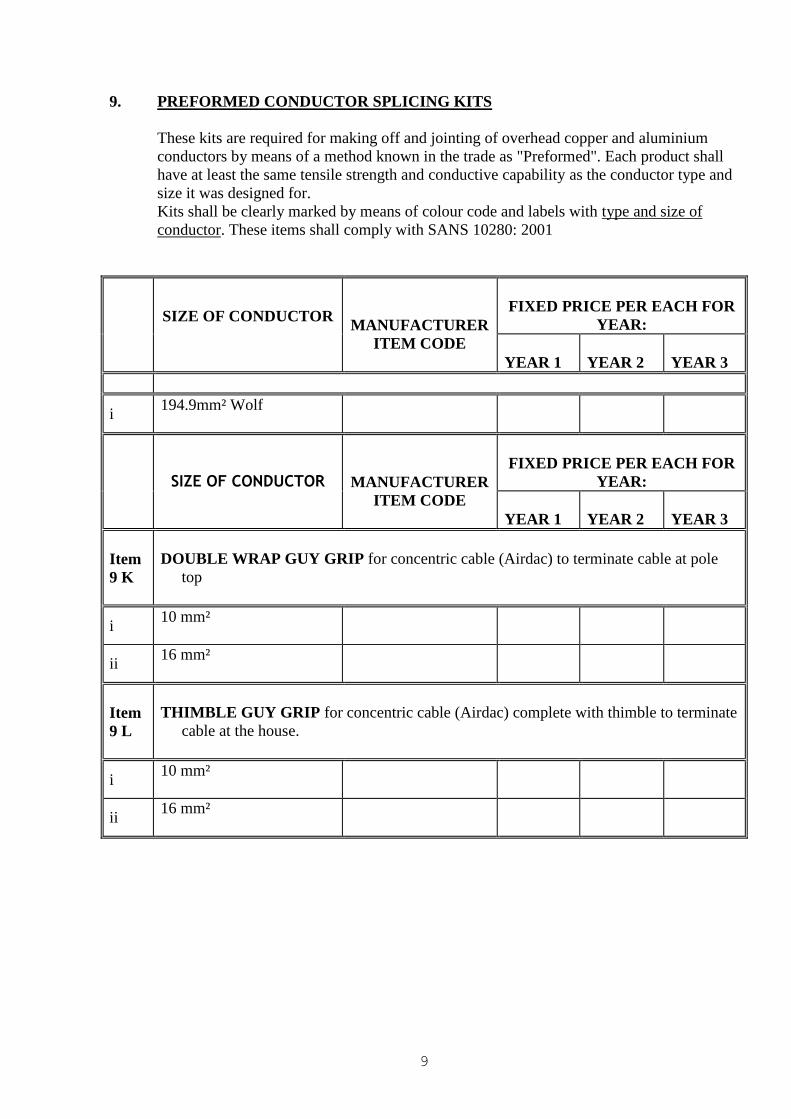
9. PREFORMED CONDUCTOR SPLICING KITS
These kits are required for making off and jointing of overhead copper and aluminium
conductors by means of a method known in the trade as "Preformed". Each product shall
have at least the same tensile strength and conductive capability as the conductor type and
size it was designed for.
Kits shall be clearly marked by means of colour code and labels with type and size of
conductor. These items shall comply with SANS 10280: 2001
SIZE OF CONDUCTOR
MANUFACTURER
ITEM CODE
FIXED PRICE PER EACH FOR
YEAR:
YEAR 1
YEAR 2
YEAR 3
i 194.9mm² Wolf
SIZE OF CONDUCTOR
MANUFACTURER
ITEM CODE
FIXED PRICE PER EACH FOR
YEAR:
YEAR 1
YEAR 2
YEAR 3
Item
9 K
DOUBLE WRAP GUY GRIP for concentric cable (Airdac) to terminate cable at pole
top
i 10 mm²
ii 16 mm²
Item
9 L
THIMBLE GUY GRIP for concentric cable (Airdac) complete with thimble to terminate
cable at the house.
i 10 mm²
ii 16 mm²
10
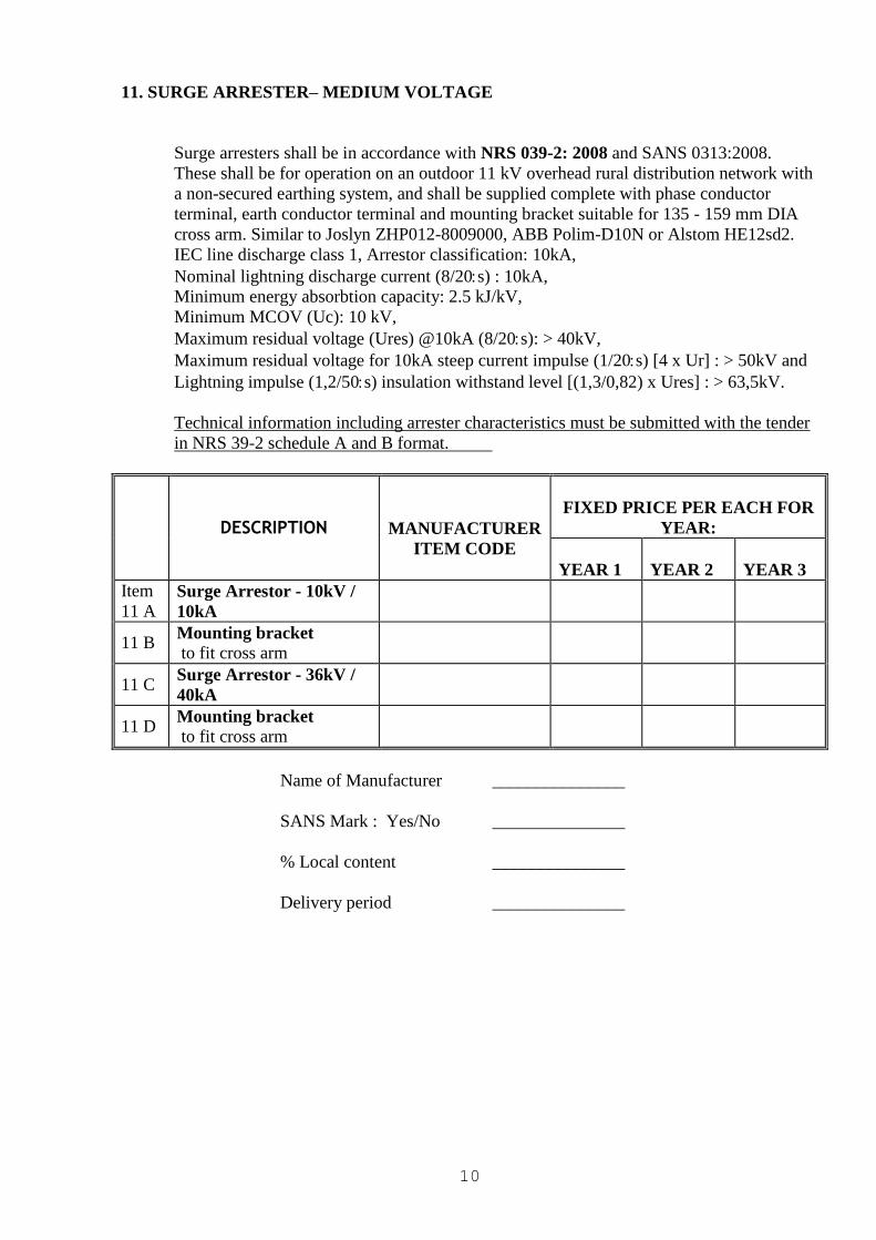
11. SURGE ARRESTER– MEDIUM VOLTAGE
Surge arresters shall be in accordance with NRS 039-2: 2008 and SANS 0313:2008.
These shall be for operation on an outdoor 11 kV overhead rural distribution network with
a non-secured earthing system, and shall be supplied complete with phase conductor
terminal, earth conductor terminal and mounting bracket suitable for 135 - 159 mm DIA
cross arm. Similar to Joslyn ZHP012-8009000, ABB Polim-D10N or Alstom HE12sd2.
IEC line discharge class 1, Arrestor classification: 10kA,
Nominal lightning discharge current (8/20s) : 10kA,
Minimum energy absorbtion capacity: 2.5 kJ/kV,
Minimum MCOV (Uc): 10 kV,
Maximum residual voltage (Ures) @10kA (8/20s): > 40kV,
Maximum residual voltage for 10kA steep current impulse (1/20s) [4 x Ur] : > 50kV and
Lightning impulse (1,2/50s) insulation withstand level [(1,3/0,82) x Ures] : > 63,5kV.
Technical information including arrester characteristics must be submitted with the tender
in NRS 39-2 schedule A and B format.
DESCRIPTION
MANUFACTURER
ITEM CODE
FIXED PRICE PER EACH FOR
YEAR:
YEAR 1
YEAR 2
YEAR 3
Item
11 A Surge Arrestor - 10kV /
10kA
11 B Mounting bracket
to fit cross arm
11 C Surge Arrestor - 36kV /
40kA
11 D Mounting bracket
to fit cross arm
Name of Manufacturer _______________
SANS Mark : Yes/No _______________
% Local content _______________
Delivery period _______________
11
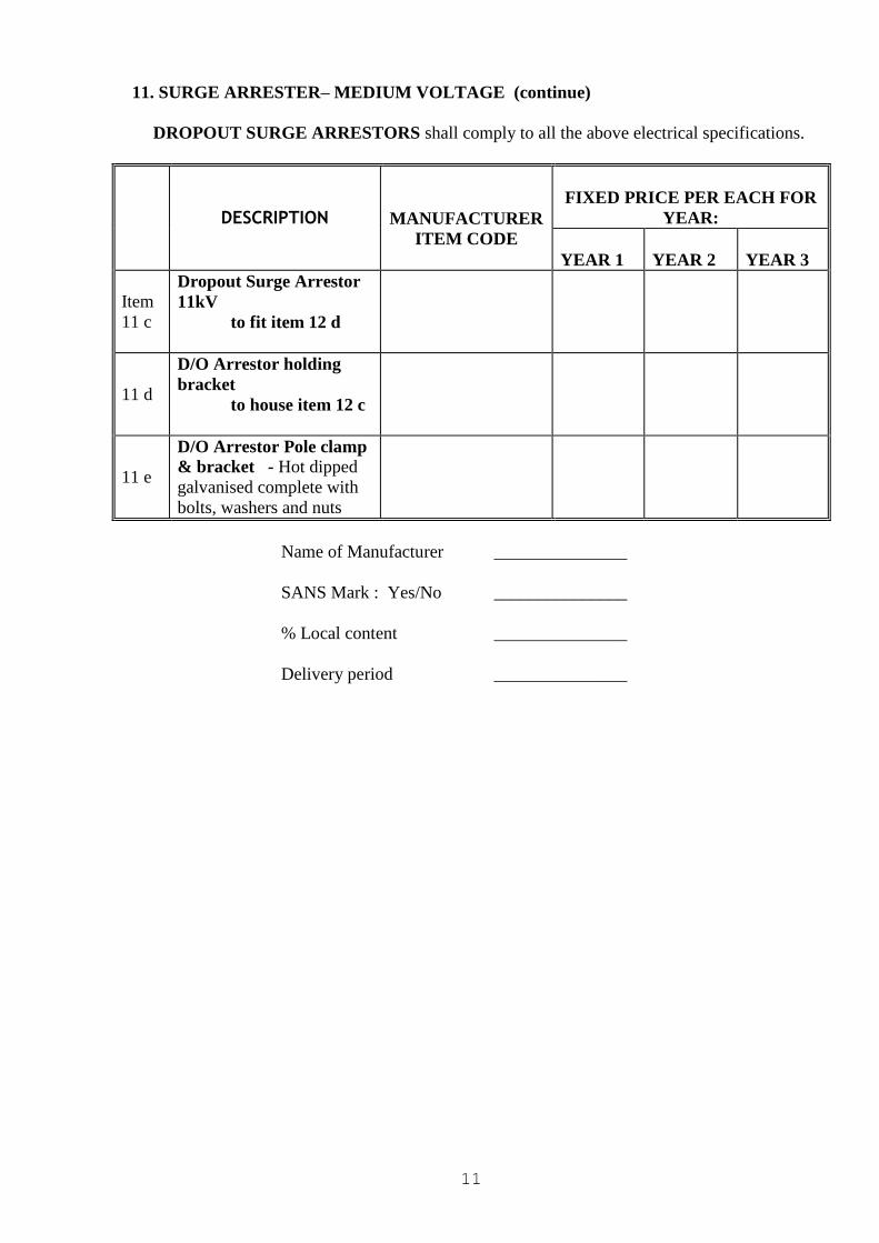
11. SURGE ARRESTER– MEDIUM VOLTAGE (continue)
DROPOUT SURGE ARRESTORS shall comply to all the above electrical specifications.
DESCRIPTION
MANUFACTURER
ITEM CODE
FIXED PRICE PER EACH FOR
YEAR:
YEAR 1
YEAR 2
YEAR 3
Item
11 c
Dropout Surge Arrestor
11kV
to fit item 12 d
11 d
D/O Arrestor holding
bracket
to house item 12 c
11 e
D/O Arrestor Pole clamp
& bracket - Hot dipped
galvanised complete with
bolts, washers and nuts
Name of Manufacturer _______________
SANS Mark : Yes/No _______________
% Local content _______________
Delivery period _______________
12
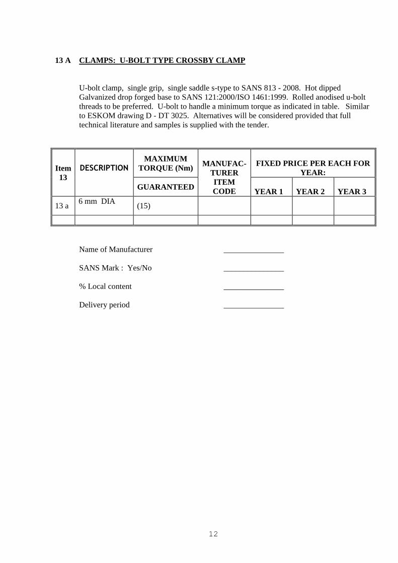
13 A CLAMPS: U-BOLT TYPE CROSSBY CLAMP
U-bolt clamp, single grip, single saddle s-type to SANS 813 - 2008. Hot dipped
Galvanized drop forged base to SANS 121:2000/ISO 1461:1999. Rolled anodised u-bolt
threads to be preferred. U-bolt to handle a minimum torque as indicated in table. Similar
to ESKOM drawing D - DT 3025. Alternatives will be considered provided that full
technical literature and samples is supplied with the tender.
Item
13
DESCRIPTION
MAXIMUM
TORQUE (Nm)
MANUFAC-
TURER
ITEM
CODE
FIXED PRICE PER EACH FOR
YEAR:
GUARANTEED
YEAR 1
YEAR 2
YEAR 3
13 a 6 mm DIA
(15)
Name of Manufacturer _______________
SANS Mark : Yes/No _______________
% Local content _______________
Delivery period _______________
13
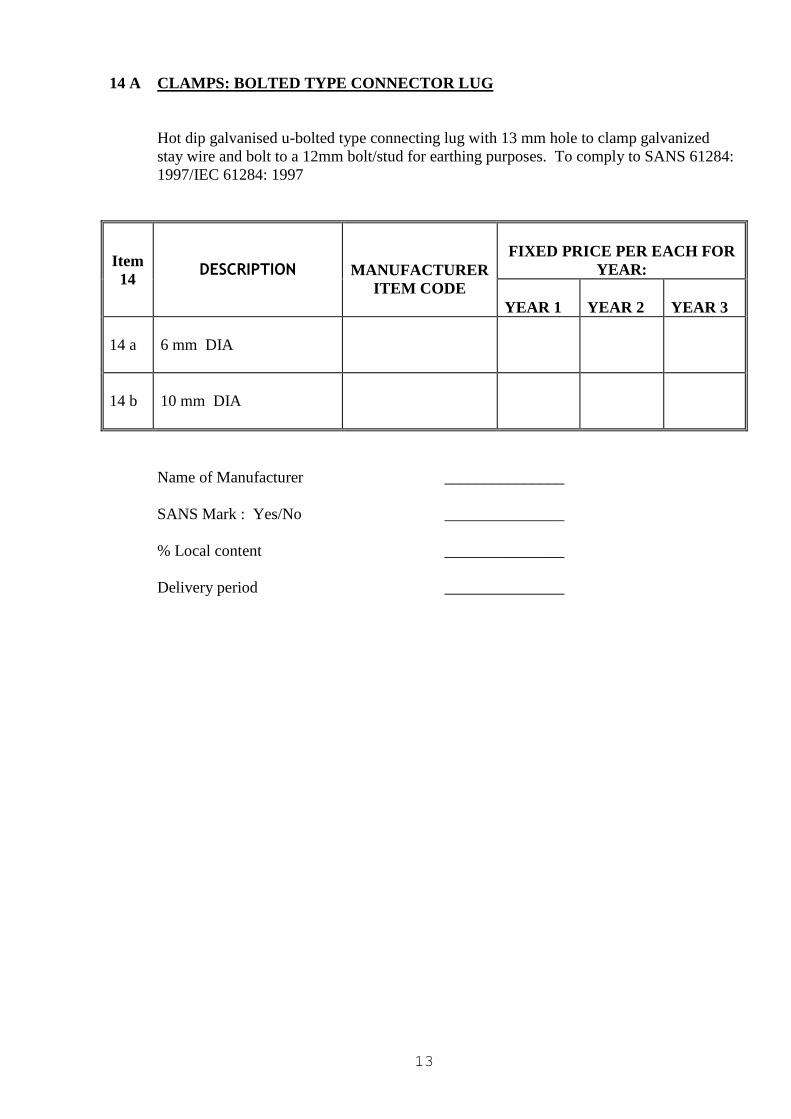
14 A CLAMPS: BOLTED TYPE CONNECTOR LUG
Hot dip galvanised u-bolted type connecting lug with 13 mm hole to clamp galvanized
stay wire and bolt to a 12mm bolt/stud for earthing purposes. To comply to SANS 61284:
1997/IEC 61284: 1997
Item
14
DESCRIPTION
MANUFACTURER
ITEM CODE
FIXED PRICE PER EACH FOR
YEAR:
YEAR 1
YEAR 2
YEAR 3
14 a
6 mm DIA
14 b
10 mm DIA
Name of Manufacturer _______________
SANS Mark : Yes/No _______________
% Local content _______________
Delivery period _______________
14
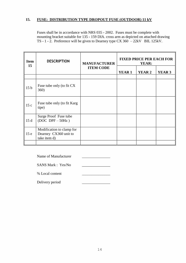
15. FUSE: DISTRIBUTION TYPE DROPOUT FUSE (OUTDOOR) 11 kV
Fuses shall be in accordance with NRS 035 - 2002. Fuses must be complete with
mounting bracket suitable for 135 - 159 DIA. cross arm as depicted on attached drawing
TS - 1 - 2. Preference will be given to Dearney type CX 360 – 22kV BIL 125kV.
Item
15
DESCRIPTION
MANUFACTURER
ITEM CODE
FIXED PRICE PER EACH FOR
YEAR:
YEAR 1
YEAR 2
YEAR 3
15 b
Fuse tube only (to fit CX
360)
15 c
Fuse tube only (to fit Karg
tipe)
15 d
Surge Proof Fuse tube
(DOC DPF – 50Hz )
15 e
Modification to clamp for
Dearney CX360 unit to
take item d)
Name of Manufacturer _______________
SANS Mark : Yes/No _______________
% Local content _______________
Delivery period _______________
15
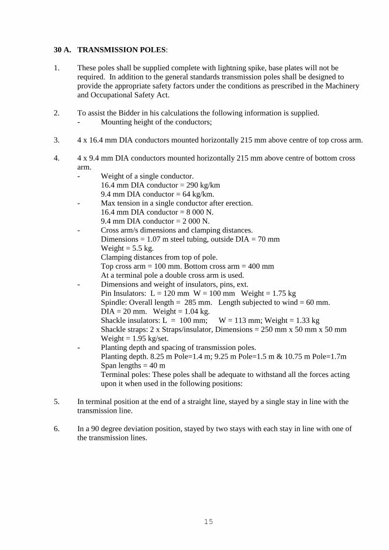
30 A. TRANSMISSION POLES:
1. These poles shall be supplied complete with lightning spike, base plates will not be
required. In addition to the general standards transmission poles shall be designed to
provide the appropriate safety factors under the conditions as prescribed in the Machinery
and Occupational Safety Act.
2. To assist the Bidder in his calculations the following information is supplied.
- Mounting height of the conductors;
3. 4 x 16.4 mm DIA conductors mounted horizontally 215 mm above centre of top cross arm.
4. 4 x 9.4 mm DIA conductors mounted horizontally 215 mm above centre of bottom cross
arm.
- Weight of a single conductor.
16.4 mm DIA conductor = 290 kg/km
9.4 mm DIA conductor = 64 kg/km.
- Max tension in a single conductor after erection.
16.4 mm DIA conductor = 8 000 N.
9.4 mm DIA conductor = 2 000 N.
- Cross arm/s dimensions and clamping distances.
Dimensions = 1.07 m steel tubing, outside DIA = 70 mm
Weight = 5.5 kg.
Clamping distances from top of pole.
Top cross arm = 100 mm. Bottom cross arm = 400 mm
At a terminal pole a double cross arm is used.
- Dimensions and weight of insulators, pins, ext.
Pin Insulators: L = 120 mm W = 100 mm Weight = 1.75 kg
Spindle: Overall length = 285 mm. Length subjected to wind = 60 mm.
DIA = 20 mm. Weight = 1.04 kg.
Shackle insulators: L = 100 mm; W = 113 mm; Weight = 1.33 kg
Shackle straps: 2 x Straps/insulator, Dimensions = 250 mm x 50 mm x 50 mm
Weight = 1.95 kg/set.
- Planting depth and spacing of transmission poles.
Planting depth. 8.25 m Pole=1.4 m; 9.25 m Pole=1.5 m & 10.75 m Pole=1.7m
Span lengths = 40 m
Terminal poles: These poles shall be adequate to withstand all the forces acting
upon it when used in the following positions:
5. In terminal position at the end of a straight line, stayed by a single stay in line with the
transmission line.
6. In a 90 degree deviation position, stayed by two stays with each stay in line with one of
the transmission lines.
16
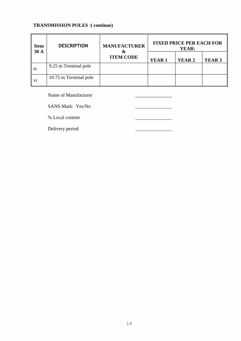
TRANSMISSION POLES :( continue)
Item
30 A
DESCRIPTION
MANUFACTURER
&
ITEM CODE
FIXED PRICE PER EACH FOR
YEAR:
YEAR 1
YEAR 2
YEAR 3
iv 9.25 m Terminal pole
vi 10.75 m Terminal pole
Name of Manufacturer _______________
SANS Mark: Yes/No _______________
% Local content _______________
Delivery period _______________
17
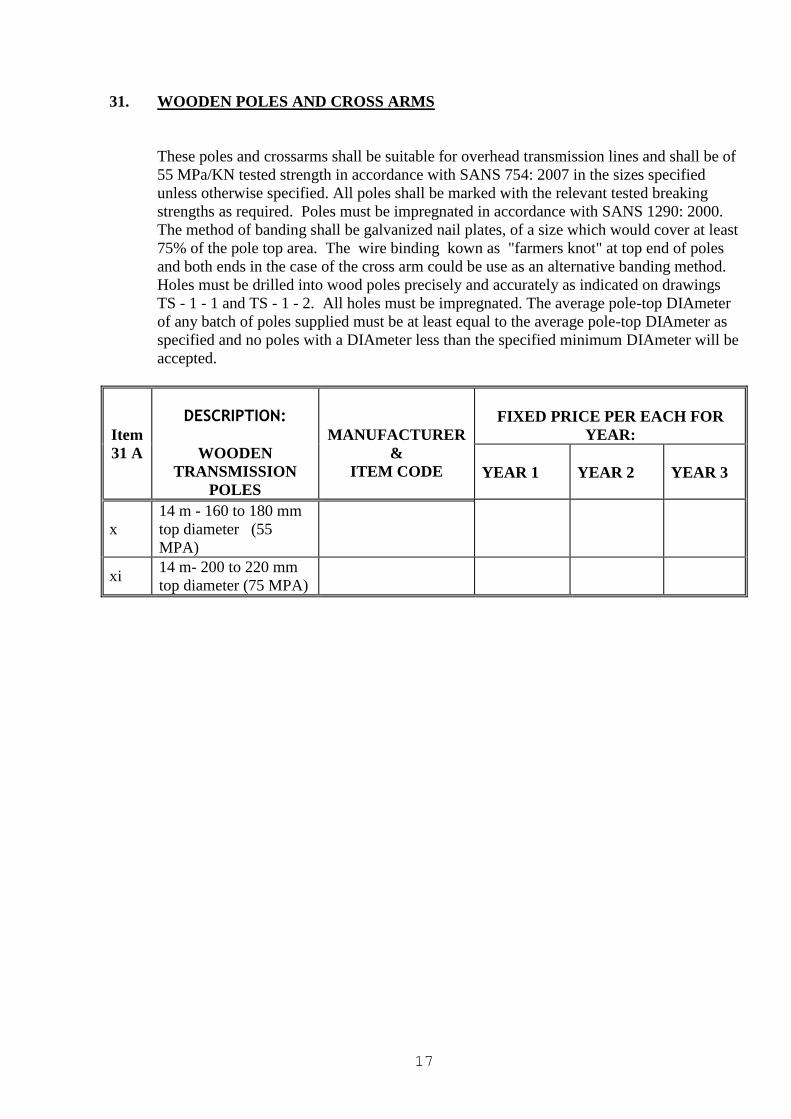
31. WOODEN POLES AND CROSS ARMS
These poles and crossarms shall be suitable for overhead transmission lines and shall be of
55 MPa/KN tested strength in accordance with SANS 754: 2007 in the sizes specified
unless otherwise specified. All poles shall be marked with the relevant tested breaking
strengths as required. Poles must be impregnated in accordance with SANS 1290: 2000.
The method of banding shall be galvanized nail plates, of a size which would cover at least
75% of the pole top area. The wire binding kown as "farmers knot" at top end of poles
and both ends in the case of the cross arm could be use as an alternative banding method.
Holes must be drilled into wood poles precisely and accurately as indicated on drawings
TS - 1 - 1 and TS - 1 - 2. All holes must be impregnated. The average pole-top DIAmeter
of any batch of poles supplied must be at least equal to the average pole-top DIAmeter as
specified and no poles with a DIAmeter less than the specified minimum DIAmeter will be
accepted.
Item
31 A
DESCRIPTION:
WOODEN
TRANSMISSION
POLES
MANUFACTURER
&
ITEM CODE
FIXED PRICE PER EACH FOR
YEAR:
YEAR 1
YEAR 2
YEAR 3
x
14 m - 160 to 180 mm
top diameter (55
MPA)
xi 14 m- 200 to 220 mm
top diameter (75 MPA)
18
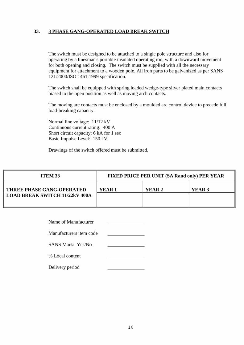
33. 3 PHASE GANG-OPERATED LOAD BREAK SWITCH
The switch must be designed to be attached to a single pole structure and also for
operating by a linesman's portable insulated operating rod, with a downward movement
for both opening and closing. The switch must be supplied with all the necessary
equipment for attachment to a wooden pole. All iron parts to be galvanized as per SANS
121:2000/ISO 1461:1999 specification.
The switch shall be equipped with spring loaded wedge-type silver plated main contacts
biased to the open position as well as moving arch contacts.
The moving arc contacts must be enclosed by a moulded arc control device to precede full
load-breaking capacity.
Normal line voltage: 11/12 kV
Continuous current rating: 400 A
Short circuit capacity: 6 kA for 1 sec
Basic Impulse Level: 150 kV
Drawings of the switch offered must be submitted.
ITEM 33 FIXED PRICE PER UNIT (SA Rand only) PER YEAR
THREE PHASE GANG-OPERATED
LOAD BREAK SWITCH 11/22kV 400A
YEAR 1
YEAR 2
YEAR 3
Name of Manufacturer _______________
Manufacturers item code _______________
SANS Mark: Yes/No _______________
% Local content _______________
Delivery period _______________
19
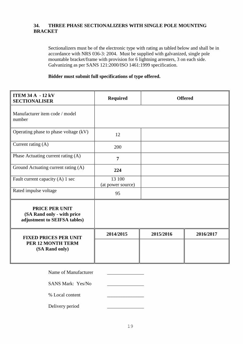
34. THREE PHASE SECTIONALIZERS WITH SINGLE POLE MOUNTING
BRACKET
Sectionalizers must be of the electronic type with rating as tabled below and shall be in
accordance with NRS 036-3: 2004. Must be supplied with galvanized, single pole
mountable bracket/frame with provision for 6 lightning arresters, 3 on each side.
Galvanizing as per SANS 121:2000/ISO 1461:1999 specification.
Bidder must submit full specifications of type offered.
ITEM 34 A - 12 kV
SECTIONALISER Required Offered
Manufacturer item code / model
number
Operating phase to phase voltage (kV)
12
Current rating (A)
200
Phase Actuating current rating (A)
7
Ground Actuating current rating (A)
224
Fault current capacity (A) 1 sec
13 100
(at power source)
Rated impulse voltage
95
PRICE PER UNIT
(SA Rand only - with price
adjustment to SEIFSA tables)
FIXED PRICES PER UNIT
PER 12 MONTH TERM
(SA Rand only)
2014/2015 2015/2016 2016/2017
Name of Manufacturer _______________
SANS Mark: Yes/No _______________
% Local content _______________
Delivery period _______________
20
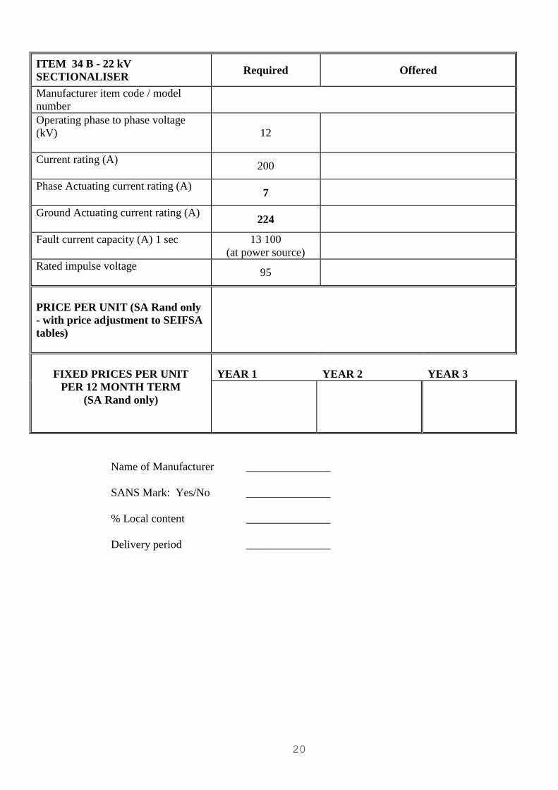
ITEM 34 B - 22 kV
SECTIONALISER Required Offered
Manufacturer item code / model
number
Operating phase to phase voltage
(kV)
12
Current rating (A)
200
Phase Actuating current rating (A)
7
Ground Actuating current rating (A)
224
Fault current capacity (A) 1 sec
13 100
(at power source)
Rated impulse voltage
95
PRICE PER UNIT (SA Rand only
- with price adjustment to SEIFSA
tables)
FIXED PRICES PER UNIT
PER 12 MONTH TERM
(SA Rand only)
YEAR 1
YEAR 2
YEAR 3
Name of Manufacturer _______________
SANS Mark: Yes/No _______________
% Local content _______________
Delivery period _______________
21
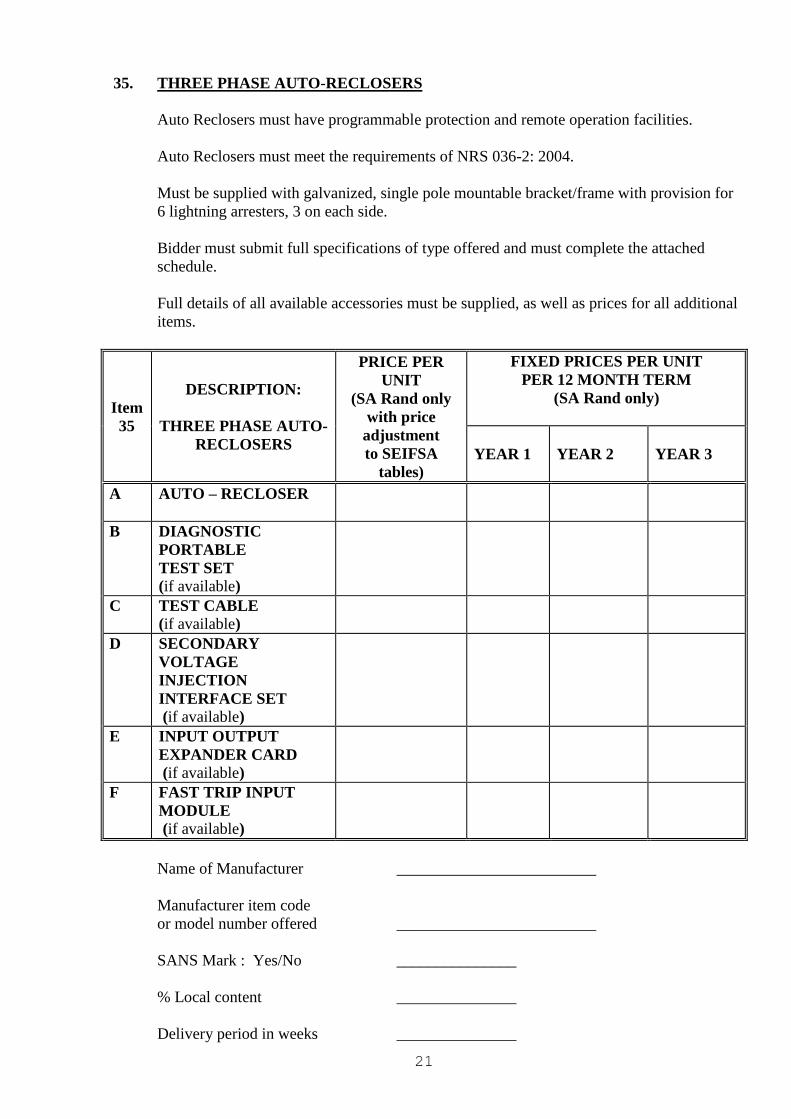
35. THREE PHASE AUTO-RECLOSERS
Auto Reclosers must have programmable protection and remote operation facilities.
Auto Reclosers must meet the requirements of NRS 036-2: 2004.
Must be supplied with galvanized, single pole mountable bracket/frame with provision for
6 lightning arresters, 3 on each side.
Bidder must submit full specifications of type offered and must complete the attached
schedule.
Full details of all available accessories must be supplied, as well as prices for all additional
items.
Item
35
DESCRIPTION:
THREE PHASE AUTO-
RECLOSERS
PRICE PER
UNIT
(SA Rand only
with price
adjustment
to SEIFSA
tables)
FIXED PRICES PER UNIT
PER 12 MONTH TERM
(SA Rand only)
YEAR 1
YEAR 2
YEAR 3
A AUTO – RECLOSER
B DIAGNOSTIC
PORTABLE
TEST SET
(if available)
C TEST CABLE
(if available)
D SECONDARY
VOLTAGE
INJECTION
INTERFACE SET
(if available)
E INPUT OUTPUT
EXPANDER CARD
(if available)
F FAST TRIP INPUT
MODULE
(if available)
Name of Manufacturer _________________________
Manufacturer item code
or model number offered _________________________
SANS Mark : Yes/No _______________
% Local content _______________
Delivery period in weeks _______________
22
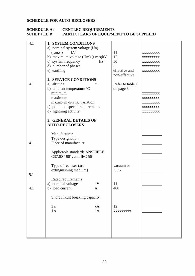
SCHEDULE FOR AUTO-RECLOSERS
SCHEDULE A: CENTLEC REQUIREMENTS
SCHEDULE B: PARTICULARS OF EQUIPMENT TO BE SUPPLIED
4.1
4.1
4.1
5.1
4.1
1. SYSTEM CONDITIONS a) nominal system voltage (Un)
(r.m.s.) kV
b) maximum voltage (Um) (r.m.s)kV
c) system frequency Hz
d) number of phases
e) earthing
2. SERVICE CONDITIONS a) altitude m
b) ambient temperature ºC
minimum
maximum
maximum diurnal variation
c) pollution special requirements
d) lightning activity
3. GENERAL DETAILS OF
AUTO-RECLOSERS
Manufacturer
Type designation
Place of manufacture
Applicable standards ANSI/IEEE
C37.60-1981, and IEC 56
Type of recloser (arc
extinguishing medium)
Rated requirements
a) nominal voltage kV
b) load current A
Short circuit breaking capacity
3 s kA
1 s kA
11
12
50
3
effective and
non-effective
Refer to table 1
on page 3
vacuum or
SF6
11
400
12
xxxxxxxxx
xxxxxxxxx
xxxxxxxxx
xxxxxxxxx
xxxxxxxxx
xxxxxxxxx
xxxxxxxxx
xxxxxxxxx
xxxxxxxxx
xxxxxxxxx
xxxxxxxxx
__________
__________
__________
__________
__________
__________
__________
__________
__________
__________
23
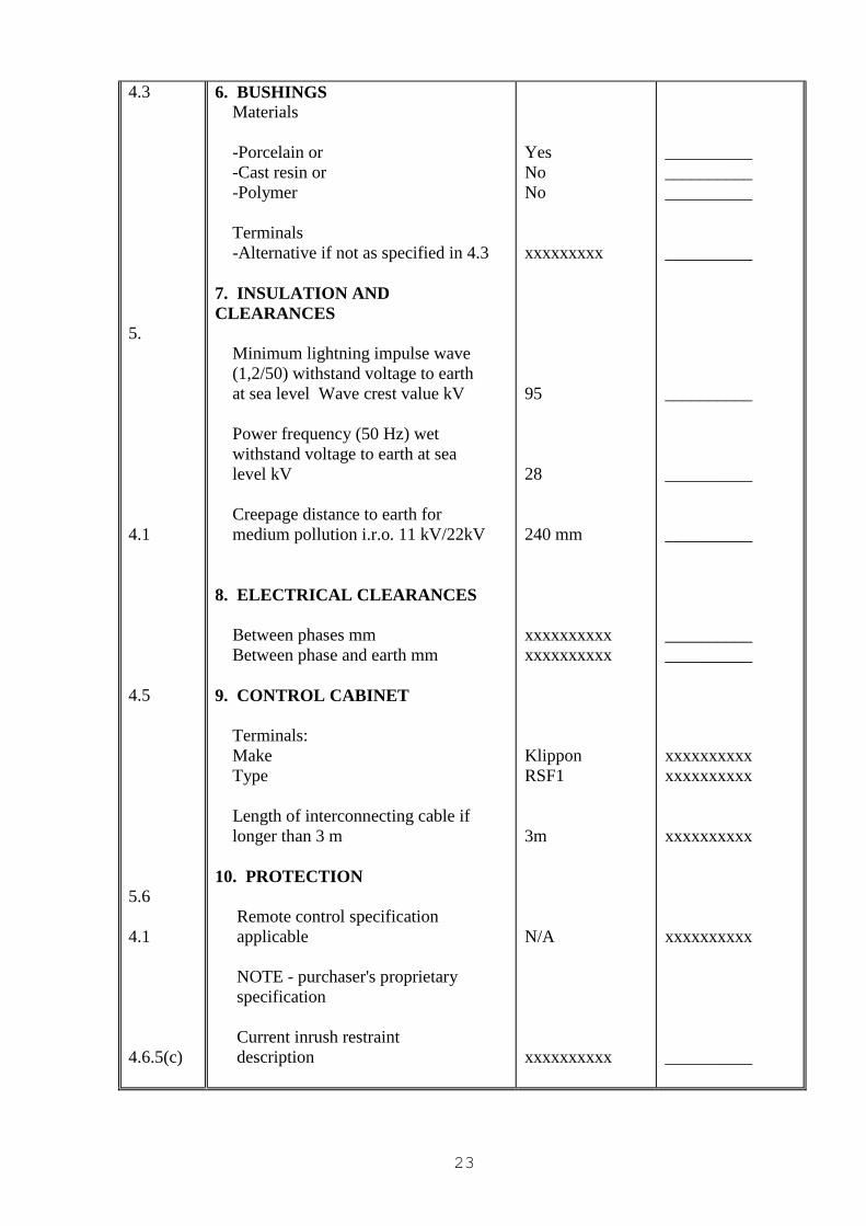
4.3
5.
4.1
4.5
5.6
4.1
4.6.5(c)
6. BUSHINGS Materials
-Porcelain or
-Cast resin or
-Polymer
Terminals
-Alternative if not as specified in 4.3
7. INSULATION AND
CLEARANCES
Minimum lightning impulse wave
(1,2/50) withstand voltage to earth
at sea level Wave crest value kV
Power frequency (50 Hz) wet
withstand voltage to earth at sea
level kV
Creepage distance to earth for
medium pollution i.r.o. 11 kV/22kV
8. ELECTRICAL CLEARANCES
Between phases mm
Between phase and earth mm
9. CONTROL CABINET
Terminals:
Make
Type
Length of interconnecting cable if
longer than 3 m
10. PROTECTION
Remote control specification
applicable
NOTE - purchaser's proprietary
specification
Current inrush restraint
description
Yes
No
No
xxxxxxxxx
95
28
240 mm
xxxxxxxxxx
xxxxxxxxxx
Klippon
RSF1
3m
N/A
xxxxxxxxxx
__________
__________
__________
__________
__________
__________
__________
__________
__________
xxxxxxxxxx
xxxxxxxxxx
xxxxxxxxxx
xxxxxxxxxx
__________
24
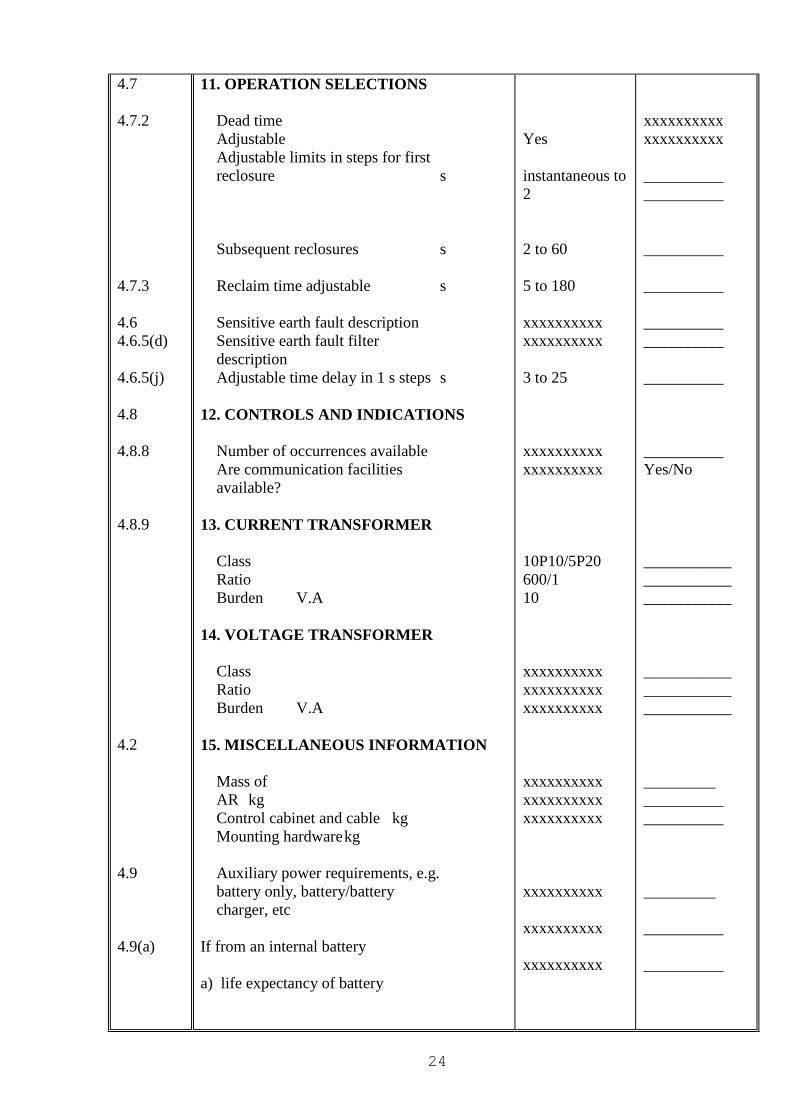
4.7
4.7.2
4.7.3
4.6
4.6.5(d)
4.6.5(j)
4.8
4.8.8
4.8.9
4.2
4.9
4.9(a)
11. OPERATION SELECTIONS
Dead time
Adjustable
Adjustable limits in steps for first
reclosure s
Subsequent reclosures s
Reclaim time adjustable s
Sensitive earth fault description
Sensitive earth fault filter
description
Adjustable time delay in 1 s steps s
12. CONTROLS AND INDICATIONS
Number of occurrences available
Are communication facilities
available?
13. CURRENT TRANSFORMER
Class
Ratio
Burden V.A
14. VOLTAGE TRANSFORMER
Class
Ratio
Burden V.A
15. MISCELLANEOUS INFORMATION
Mass of
AR kg
Control cabinet and cable kg
Mounting hardware kg
Auxiliary power requirements, e.g.
battery only, battery/battery
charger, etc
If from an internal battery
a) life expectancy of battery
Yes
instantaneous to
2
2 to 60
5 to 180
xxxxxxxxxx
xxxxxxxxxx
3 to 25
xxxxxxxxxx
xxxxxxxxxx
10P10/5P20
600/1
10
xxxxxxxxxx
xxxxxxxxxx
xxxxxxxxxx
xxxxxxxxxx
xxxxxxxxxx
xxxxxxxxxx
xxxxxxxxxx
xxxxxxxxxx
xxxxxxxxxx
xxxxxxxxxx
xxxxxxxxxx
__________
__________
__________
__________
__________
__________
__________
__________
Yes/No
___________
___________
___________
___________
___________
___________
_________
__________
__________
_________
__________
__________
25
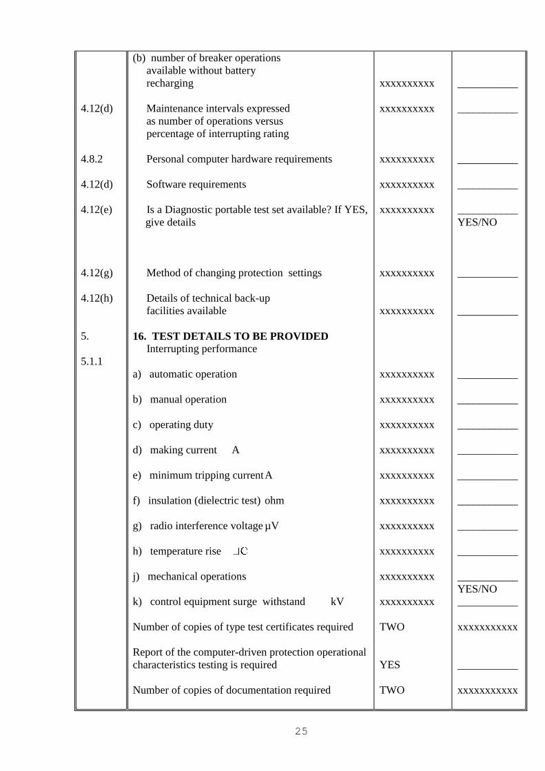
4.12(d)
4.8.2
4.12(d)
4.12(e)
4.12(g)
4.12(h)
5.
5.1.1
(b) number of breaker operations
available without battery
recharging
Maintenance intervals expressed
as number of operations versus
percentage of interrupting rating
Personal computer hardware requirements
Software requirements
Is a Diagnostic portable test set available? If YES,
give details
Method of changing protection settings
Details of technical back-up
facilities available
16. TEST DETAILS TO BE PROVIDED Interrupting performance
a) automatic operation
b) manual operation
c) operating duty
d) making current A
e) minimum tripping current A
f) insulation (dielectric test) ohm
g) radio interference voltage µV
h) temperature rise
j) mechanical operations
k) control equipment surge withstand kV
Number of copies of type test certificates required
Report of the computer-driven protection operational
characteristics testing is required
Number of copies of documentation required
xxxxxxxxxx
xxxxxxxxxx
xxxxxxxxxx
xxxxxxxxxx
xxxxxxxxxx
xxxxxxxxxx
xxxxxxxxxx
xxxxxxxxxx
xxxxxxxxxx
xxxxxxxxxx
xxxxxxxxxx
xxxxxxxxxx
xxxxxxxxxx
xxxxxxxxxx
xxxxxxxxxx
xxxxxxxxxx
xxxxxxxxxx
TWO
YES
TWO
___________
___________
___________
___________
___________
YES/NO
___________
___________
___________
___________
___________
___________
___________
___________
___________
___________
___________
YES/NO
___________
xxxxxxxxxxx
___________
xxxxxxxxxxx
26
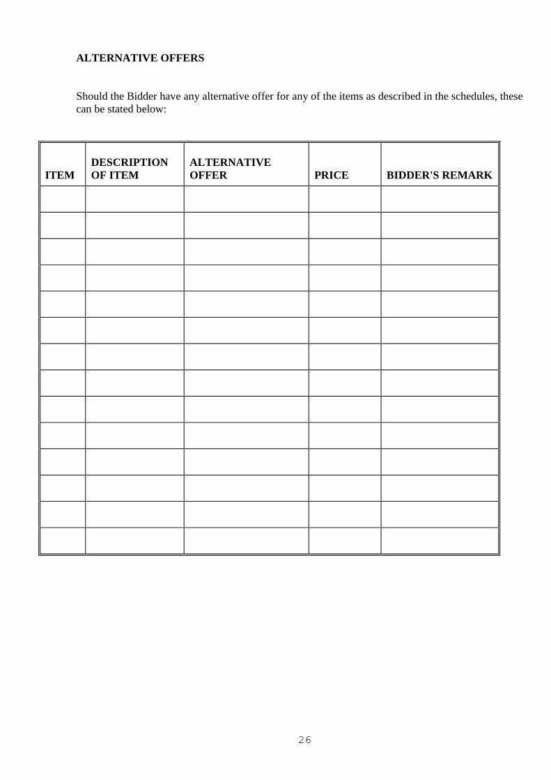
ALTERNATIVE OFFERS
Should the Bidder have any alternative offer for any of the items as described in the schedules, these
can be stated below:
ITEM
DESCRIPTION
OF ITEM
ALTERNATIVE
OFFER
PRICE
BIDDER'S REMARK
27
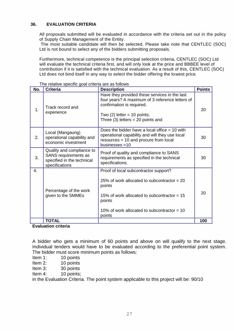
36. EVALUATION CRITERIA
All proposals submitted will be evaluated in accordance with the criteria set out in the policy of Supply Chain Management of the Entity.
The most suitable candidate will then be selected. Please take note that CENTLEC (SOC) Ltd is not bound to select any of the bidders submitting proposals.
Furthermore, technical competence is the principal selection criteria, CENTLEC (SOC) Ltd
will evaluate the technical criteria first, and will only look at the price and BBBEE level of contribution if it is satisfied with the technical evaluation. As a result of this, CENTLEC (SOC) Ltd does not bind itself in any way to select the bidder offering the lowest price.
The relative specific goal criteria are as follows
No. Criteria Description Points
1. Track record and experience
Have they provided these services in the last four years? A maximum of 3 reference letters of confirmation is required. Two (2) letter = 10 points; Three (3) letters = 20 points and
20
2. Local (Mangaung) operational capability and economic investment
Does the bidder have a local office = 10 with operational capability and will they use local resources = 10 and procure from local businesses =10
30
3.
Quality and compliance to SANS requirements as specified in the technical specifications
Proof of quality and compliance to SANS requirements as specified in the technical specifications.
30
4.
Percentage of the work given to the SMMEs
Proof of local subcontractor support? 25% of work allocated to subcontractor = 20 points 15% of work allocated to subcontractor = 15 points 10% of work allocated to subcontractor = 10 points
20
TOTAL 100
Evaluation criteria
A bidder who gets a minimum of 60 points and above on will qualify to the next stage. Individual tenders would have to be evaluated according to the preferential point system. The bidder must score minimum points as follows: Item 1: 10 points Item 2: 10 points Item 3: 30 points Item 4: 10 points; in the Evaluation Criteria. The point system applicable to this project will be: 90/10
28
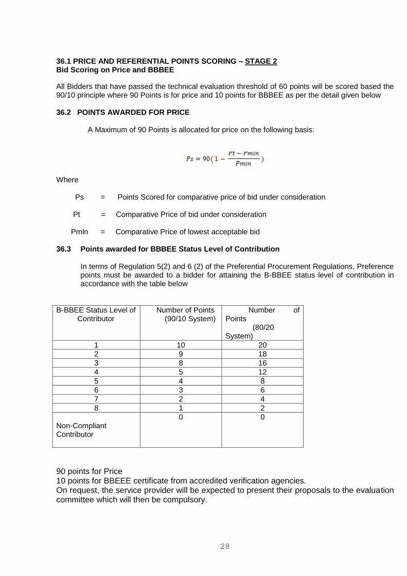
36.1 PRICE AND REFERENTIAL POINTS SCORING – STAGE 2 Bid Scoring on Price and BBBEE
All Bidders that have passed the technical evaluation threshold of 60 points will be scored based the 90/10 principle where 90 Points is for price and 10 points for BBBEE as per the detail given below 36.2 POINTS AWARDED FOR PRICE A Maximum of 90 Points is allocated for price on the following basis:
Where Ps = Points Scored for comparative price of bid under consideration Pt = Comparative Price of bid under consideration Pmln = Comparative Price of lowest acceptable bid 36.3 Points awarded for BBBEE Status Level of Contribution
In terms of Regulation 5(2) and 6 (2) of the Preferential Procurement Regulations, Preference points must be awarded to a bidder for attaining the B-BBEE status level of contribution in accordance with the table below
B-BBEE Status Level of Contributor
Number of Points (90/10 System)
Number of Points (80/20 System)
1 10 20
2 9 18
3 8 16
4 5 12
5 4 8
6 3 6
7 2 4
8 1 2
Non-Compliant Contributor
0 0
90 points for Price 10 points for BBEEE certificate from accredited verification agencies. On request, the service provider will be expected to present their proposals to the evaluation committee which will then be compulsory.

29
37. Contact information 37.1 For any further technical information regarding the document contents please contact Mr Andre
Oelofse e-mail: [email protected]. Such queries must be done in writing, the email address provided serves this purpose. The answer to one question will be sent to all the other prospective bidders that have bought the bid documents.
37.2 For telephonic enquiries Mr Andre Oelofse can be contacted at 051 409 2290. Please note that
that telephonic enquiries that are about the document contents will not be entertained as they may prejudice other prospective bidders that have bought the bid documents.
37.3 For Supply Chain Related questions, Please contact Mr. Allistair Marais at 051 412 2622 or at