Embed Size (px)
Citation preview

S82 W18717 Gemini DriveMuskego, Wisconsin 53150
Phone: (877) 622-2694Fax: (888) 679-3319
www.nabcoentrances.comTechnical Support: (866) 622-8325
WARNINGDo Not install or service this product unless Safety Practices, Warning Labels, Installation instructions, and
Operating Instructions, have been read and fully understood.
Failure to so do may result in bodily injury or property damage.
Part #15-10744 Rev. 9/19/14
Overhead Concealed Swing Door Systems
Bottom Load Models: GT 300 and GT 350 Side Load Models: GT 8300 and GT 8350
GT 8300GT 8350
GT 300GT 350DN 0376

THIS PAGE IS INTENTIONALLY LEFT BLANK

Rev. 9-19-14 Part #15-10744www.NabcoEntrances.com� GT�300-350-8300-8350�OHC�Swing�Door�Installation
i
Table of Contents
Warning Labels . . . . . . . . . . . . . . . . . . . . . . . . . . . . . . . . . . . . . . . . . . . . . . . . . . . . . . . . . . . . . . . . . . . . iiiGeneral Safety Recommendations . . . . . . . . . . . . . . . . . . . . . . . . . . . . . . . . . . . . . . . . . . . . . . . . . . . . iv
CHAPTER 1: SCOPE . . . . . . . . . . . . . . . . . . . . . . . . . . . . . . . . . . . . . . . . . . . . . . . . . . . . . . .1-5
Section 1a: To�the�Installer . . . . . . . . . . . . . . . . . . . . . . . . . . . . . . . . . . . . . . . . . . . . . . . . . . . . . . . . . . .1-5
Section 1b: Objective . . . . . . . . . . . . . . . . . . . . . . . . . . . . . . . . . . . . . . . . . . . . . . . . . . . . . . . . . . . . . . . .1-5
CHAPTER 2: GETTING STARTED . . . . . . . . . . . . . . . . . . . . . . . . . . . . . . . . . . . . . . . . . . . .2-6
Section 2a: Mechanical�Configurations . . . . . . . . . . . . . . . . . . . . . . . . . . . . . . . . . . . . . . . . . . . . . . . . .2-6
Section 2b: Electrical�Standards . . . . . . . . . . . . . . . . . . . . . . . . . . . . . . . . . . . . . . . . . . . . . . . . . . . . . . .2-6
Section 2c: Installation�Specifications . . . . . . . . . . . . . . . . . . . . . . . . . . . . . . . . . . . . . . . . . . . . . . . . . .2-6
Section 2d: Base�Unit�Types . . . . . . . . . . . . . . . . . . . . . . . . . . . . . . . . . . . . . . . . . . . . . . . . . . . . . . . . . .2-6
Section 2e: Header�Types . . . . . . . . . . . . . . . . . . . . . . . . . . . . . . . . . . . . . . . . . . . . . . . . . . . . . . . . . . . .2-7
Section 2f: How�to�Determine�Handing . . . . . . . . . . . . . . . . . . . . . . . . . . . . . . . . . . . . . . . . . . . . . . . . .2-7
Section 2g: Swing�Door�Types . . . . . . . . . . . . . . . . . . . . . . . . . . . . . . . . . . . . . . . . . . . . . . . . . . . . . . . . .2-8
Section 2h: Control�Types . . . . . . . . . . . . . . . . . . . . . . . . . . . . . . . . . . . . . . . . . . . . . . . . . . . . . . . . . . . .2-9
Section 2i: Emergency�Egress . . . . . . . . . . . . . . . . . . . . . . . . . . . . . . . . . . . . . . . . . . . . . . . . . . . . . . . . .2-9
Section 2j: Associated�Manuals�Part�Number . . . . . . . . . . . . . . . . . . . . . . . . . . . . . . . . . . . . . . . . . . . .2-9
CHAPTER 3: PREPARE THE ROUGH OPENING . . . . . . . . . . . . . . . . . . . . . . . . . . . . . . 3-10
CHAPTER 4: ASSEMBLE THE DOOR FRAME . . . . . . . . . . . . . . . . . . . . . . . . . . . . . . . . 4-11
Section 4a: Prep�the�Bottom�Load�Header . . . . . . . . . . . . . . . . . . . . . . . . . . . . . . . . . . . . . . . . . . . . .4-11
Section 4b: Prep�the�Jamb�Tubes . . . . . . . . . . . . . . . . . . . . . . . . . . . . . . . . . . . . . . . . . . . . . . . . . . . . .4-14
Section 4c: Install�the�Header�to�Jamb�Tubes . . . . . . . . . . . . . . . . . . . . . . . . . . . . . . . . . . . . . . . . . . .4-15
CHAPTER 5: INSTALL FRAME TO BUILDING . . . . . . . . . . . . . . . . . . . . . . . . . . . . . . . . 5-16
Section 5a: Secure�Frame�to�Rough�Opening . . . . . . . . . . . . . . . . . . . . . . . . . . . . . . . . . . . . . . . . . . .5-16
Section 5b: Install�the�Finger�Guard . . . . . . . . . . . . . . . . . . . . . . . . . . . . . . . . . . . . . . . . . . . . . . . . . . .5-17

GT�300-350-8300-8350�OHC�Swing�Door�Installation� www.NabcoEntrances.comPart #15-10744 Rev. 9-19-14
ii
CHAPTER 6: INSTALL BOTTOM LOAD COMPONENTS . . . . . . . . . . . . . . . . . . . . . . . . 6-19
Section 6a: Secure�Incoming�Wires . . . . . . . . . . . . . . . . . . . . . . . . . . . . . . . . . . . . . . . . . . . . . . . . . . .6-19
Section 6b: Install�Motor/Operator�into�Header . . . . . . . . . . . . . . . . . . . . . . . . . . . . . . . . . . . . . . . . .6-19
Section 6c: Install�the�Control . . . . . . . . . . . . . . . . . . . . . . . . . . . . . . . . . . . . . . . . . . . . . . . . . . . . . . . .6-20
Section 6d: Install�Optional�Components . . . . . . . . . . . . . . . . . . . . . . . . . . . . . . . . . . . . . . . . . . . . . .6-21
CHAPTER 7: 110 VAC GENERAL WIRING . . . . . . . . . . . . . . . . . . . . . . . . . . . . . . . . . . . 7-22
CHAPTER 8: INSTALL THE FLOOR PIVOT . . . . . . . . . . . . . . . . . . . . . . . . . . . . . . . . . . . 8-23
CHAPTER 9: INSTALL THE SADDLE THRESHOLD . . . . . . . . . . . . . . . . . . . . . . . . . . . . 9-23
CHAPTER 10: INSTALL THE SWING DOOR . . . . . . . . . . . . . . . . . . . . . . . . . . . . . . . . . 10-23
Section 10a: Install�the�NABCO�Swing�Door . . . . . . . . . . . . . . . . . . . . . . . . . . . . . . . . . . . . . . . . . . 10-23
Section 10b: Install�the�Swing�Door�(Not�provided�by�NABCO) . . . . . . . . . . . . . . . . . . . . . . . . . . . 10-24
CHAPTER 11: INSTALL THE SWING ARM . . . . . . . . . . . . . . . . . . . . . . . . . . . . . . . . . . 11-31
Section 11a: Set�Pre-Load . . . . . . . . . . . . . . . . . . . . . . . . . . . . . . . . . . . . . . . . . . . . . . . . . . . . . . . . . 11-31
Section 11b: Secure�the�Swing�Arm . . . . . . . . . . . . . . . . . . . . . . . . . . . . . . . . . . . . . . . . . . . . . . . . . 11-32
Section 11c: Test�the�Pre-Load . . . . . . . . . . . . . . . . . . . . . . . . . . . . . . . . . . . . . . . . . . . . . . . . . . . . . 11-34
CHAPTER 12: PRE-LOAD ADJUSTMENTS . . . . . . . . . . . . . . . . . . . . . . . . . . . . . . . . . . 12-35
Section 12a: Rotate�the�Cam�for�Back�Check . . . . . . . . . . . . . . . . . . . . . . . . . . . . . . . . . . . . . . . . . . 12-35
Section 12b: Adjust�the�Swing�Arm�for�Latch�Check . . . . . . . . . . . . . . . . . . . . . . . . . . . . . . . . . . . . 12-36
Rev. 9-19-14 Part #15-10744www.NabcoEntrances.com� GT�300-350-8300-8350�OHC�Swing�Door�Installation
iii
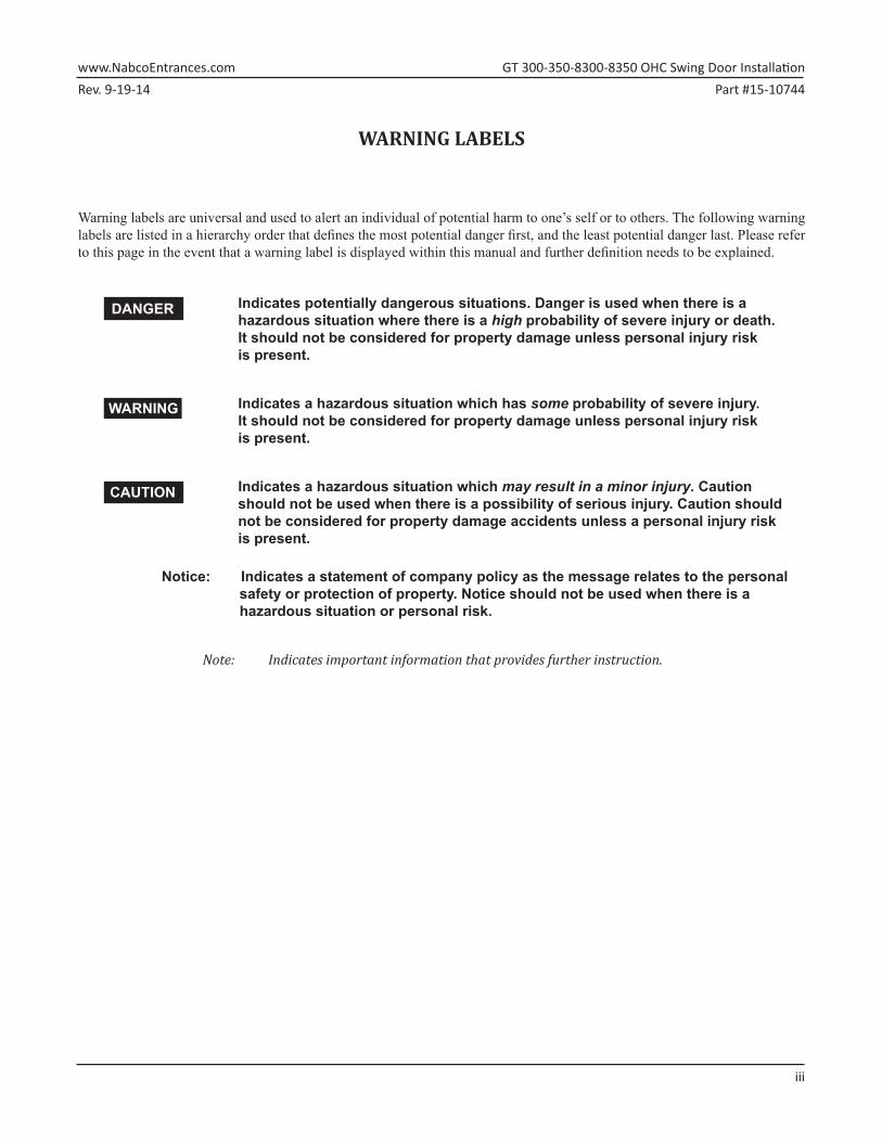
WARNING LABELS
Warning labels are universal and used to alert an individual of potential harm to one’s self or to others. The following warning labels are listed in a hierarchy order that defines the most potential danger first, and the least potential danger last. Please refer to this page in the event that a warning label is displayed within this manual and further definition needs to be explained.
Indicates potentially dangerous situations. Danger is used when there is a hazardous situation where there is a high probability of severe injury or death. It should not be considered for property damage unless personal injury risk is present.
Indicates a hazardous situation which has some probability of severe injury. It should not be considered for property damage unless personal injury risk is present.
Indicates a hazardous situation which may result in a minor injury. Caution should not be used when there is a possibility of serious injury. Caution should not be considered for property damage accidents unless a personal injury risk is present.
Notice: Indicates a statement of company policy as the message relates to the personal safety or protection of property. Notice should not be used when there is a hazardous situation or personal risk.
Note: Indicates important information that provides further instruction.
DANGER
WARNING
CAUTION
GT�300-350-8300-8350�OHC�Swing�Door�Installation� www.NabcoEntrances.comPart #15-10744 Rev. 9-19-14
iv
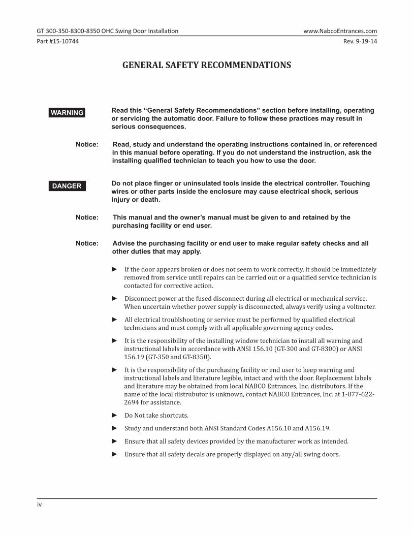
GENERAL SAFETY RECOMMENDATIONS
Read this “General Safety Recommendations” section before installing, operating or servicing the automatic door. Failure to follow these practices may result in serious consequences.
Notice: Read, study and understand the operating instructions contained in, or referenced in this manual before operating. If you do not understand the instruction, ask the installing qualified technician to teach you how to use the door.
Do not place finger or uninsulated tools inside the electrical controller. Touching wires or other parts inside the enclosure may cause electrical shock, serious injury or death.
Notice: This manual and the owner’s manual must be given to and retained by the purchasing facility or end user.
Notice: Advise the purchasing facility or end user to make regular safety checks and all other duties that may apply.
►► If the door appears broken or does not seem to work correctly, it should be immediately removed from service until repairs can be carried out or a qualified service technician is contacted for corrective action.
►► Disconnect power at the fused disconnect during all electrical or mechanical service. When uncertain whether power supply is disconnected, always verify using a voltmeter.
►► All electrical troublshooting or service must be performed by qualified electrical technicians and must comply with all applicable governing agency codes.
►► It is the responsibility of the installing window technician to install all warning and instructional labels in accordance with ANSI 156.10 (GT-300 and GT-8300) or ANSI 156.19 (GT-350 and GT-8350).
►► It is the responsibility of the purchasing facility or end user to keep warning and instructional labels and literature legible, intact and with the door. Replacement labels and literature may be obtained from local NABCO Entrances, Inc. distributors. If the name of the local distrubutor is unknown, contact NABCO Entrances, Inc. at 1-877-622-2694 for assistance.
►► Do Not take shortcuts.
►► Study and understand both ANSI Standard Codes A156.10 and A156.19.
►► Ensure that all safety devices provided by the manufacturer work as intended.
►► Ensure that all safety decals are properly displayed on any/all swing doors.
WARNING
DANGER
Rev. 9-19-14 Part #15-10744www.NabcoEntrances.com� GT�300-350-8300-8350�OHC�Swing�Door�Installation
Scope� 1-5
CHAPTER 1: SCOPE
Section 1a: To the Installer
The purpose of this manual is to familiarize the installer and purchaser with the proper installation and operation of this system. It is essential that this equipment be properly installed and operational before the door is used by the public. It is the installer’s responsibility to inspect the operation of the entrance system to be sure it complies with any applicable standards. In the United States, ANSI Standard 156.10 (GT-300 and GT-8300) or ANSI Standard 156.19 (GT-350 and GT-8350) covers these types of doors. Other local standards or codes may apply. Use them in addition to the ANSI standard. The GT-300, GT-8300, GT-350 and GT-8350 OHC are listed with the Underwriters Laboratory and is identified as such on the label.
Instruct the building owners and operator on the essentials of the operation of the door and this device. The owner should follow these instructions to determine whether the door is operating properly and should immediately call for service if there is any malfunction. All installation changes and adjustments must be made by qualified, NABCO trained technicians.
The OHC Header assembly can be purchased as a standalone unit and may be installed on other makes of doors and frames in lieu of the NABCO Complete Swing Door System.
Section 1b: Objective
The GT-300, GT-8300, GT-350 and GT-8350 OHC swing door series is designed inline with the frame as a concealed unit. The door function is operated by the Magnum IV Control Board which offers many features to accommodate most installation options. This manual offers step by step instructions to install each of the GT-300, GT-8300, GT-350 and GT-8350 OHC swing door units.
GT�300-350-8300-8350�OHC�Swing�Door�Installation� www.NabcoEntrances.comPart #15-10744 Rev. 9-19-14
2-6� Getting�Started
CHAPTER 2: GETTING STARTED
Section 2a: Mechanical Configurations
Base Model OHC Bottom Load OHC Side LoadFull Automatic GT300 GT8300Low Energy GT350 GT8350
Section 2b: Electrical StandardsNote: It is recommended for the Installer to use an Electrical Conduit to house all incoming 120 VAC wires.
Note: All wiring must conform to standard wiring practices and be in accordance with national and local electrical codes.
Electricity DescriptionPower Input 120 (±10%) AC 50-60Hz, 10 AmpsAvailable Current for accessories 0.5 Amps 24 VACAvailable wire size for incoming power 14 AWG
Section 2c: Installation Specifications
Specification MeasurementMinimum Frame Face for Mounting 1-3/4 inches (44mm)Minimum Clearance from Top of Door to Ceiling Bottom Load Side Load
6-1/8” (156 mm) 7-18” (181 mm)Minimum Door Thickness 1-3/4 inches (44 mm)Door Width Specified when ordered
Section 2d: Base Unit Types 2.d.a: Full Power Swing Doors
X Utilize Sensor(s) to open a Swing door.• Sensors activate the Control by detecting motion of pedestrians (or moving objects) that
come into range. X Must be compliant with ANSI Standard Code 156.10 to reduce chance of injury to pedestrians
and wheeled traffic.
2.d.b: Low Energy Swing Doors X Utilize a Knowing Act to open a Swing door.
• A conscious effort that is carried out in many different ways, including (but not limited to): manually opening/closing a Swing door; pressing various types of Push Plates; turning a Key switch; flipping a Rocker Switch; utilizing a keypad or card reader, etc.
X Must be compliant with the ANSI Standard Code 156.19 to reduce chance of injury to pedestrians and wheeled traffic.
Rev. 9-19-14 Part #15-10744www.NabcoEntrances.com� GT�300-350-8300-8350�OHC�Swing�Door�Installation
Getting�Started� 2-7
Always remove the bottom portion of the HandiCap Label stating “Push Door To Operate” if the “Push-n-Go” feature is not being used.
DN 1108
PUSH DOORTO OPERATE
NABCO Entrances, Inc. p/n 148701
AUTOMATIC DOOR
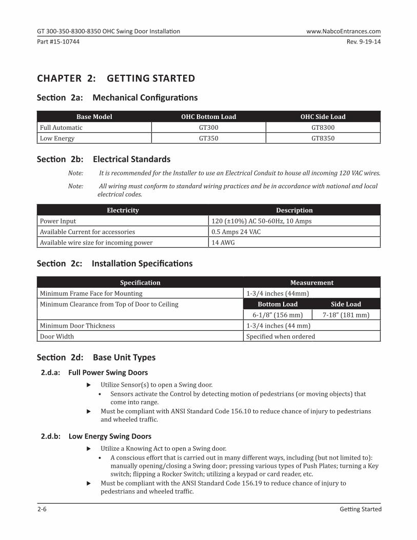
Section 2e: Header Types
SIDE LOADHEADER
Access Cover
Swing Arm
5.50”
6.00”
1.00”
DN 0530
BOTTOM LOADHEADER
Access Cover
Swing Arm
5.50”
5.00”
1.00”
Figure 2-1 Two Types of Headers
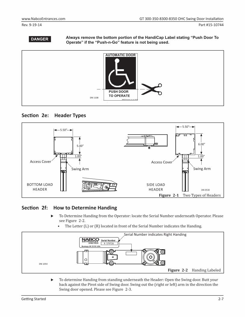
Section 2f: How to Determine Handing X To Determine Handing from the Operator: locate the Serial Number underneath Operator. Please
see Figure 2-2.• The Letter (L) or (R) located in front of the Serial Number indicates the Handing.
DN 1054
Muskego, WI 53150 USA
Serial NumberGYRO TECH
ENTRANCESR 579726
Serial Number indicates Right Handing
Figure 2-2 Handing Labeled
X To determine Handing from standing underneath the Header: Open the Swing door. Butt your back against the Pivot side of Swing door. Swing out the (right or left) arm in the direction the Swing door opened. Please see Figure 2-3.
DANGER
GT�300-350-8300-8350�OHC�Swing�Door�Installation� www.NabcoEntrances.comPart #15-10744 Rev. 9-19-14
2-8� Getting�Started
RIGHT HANDING
DN 1049 LEFT HANDING
Pivot S� le on Swing Door Swing Door
Figure 2-3 Stand with back against Pivot Side of Swing door
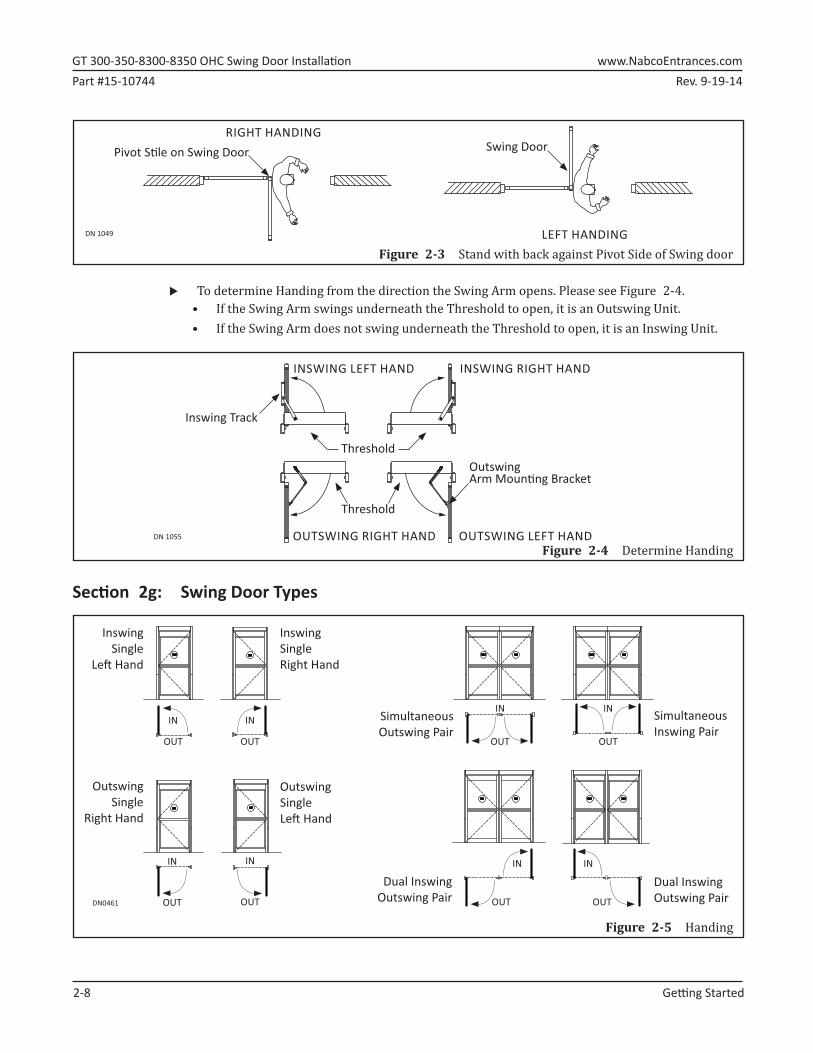
X To determine Handing from the direction the Swing Arm opens. Please see Figure 2-4.• If the Swing Arm swings underneath the Threshold to open, it is an Outswing Unit.• If the Swing Arm does not swing underneath the Threshold to open, it is an Inswing Unit.
DN 1055
INSWING LEFT HAND INSWING RIGHT HAND
Threshold
OUTSWING LEFT HANDOUTSWING RIGHT HAND
Inswing Track
OutswingArm Moun� ng Bracket
Threshold
Figure 2-4 Determine Handing
Section 2g: Swing Door Types
Figure 2-5 Handing
DN0461
InswingSingleRight Hand
InswingSingle
Le� Hand
IN
OUT
IN
OUT
IN
OUT
IN
OUT
IN
OUT
IN
OUT
IN
OUT
IN
OUT
Simultaneous Outswing Pair
Simultaneous Inswing Pair
OutswingSingle
Right Hand
OutswingSingleLe� Hand
Dual InswingOutswing Pair
Dual InswingOutswing Pair

Rev. 9-19-14 Part #15-10744www.NabcoEntrances.com� GT�300-350-8300-8350�OHC�Swing�Door�Installation
Getting�Started� 2-9
Section 2h: Control TypesThe Control is programmed to open/close the Swing door according to how the door will be used in terms of Handing, Speed, Time Delay, Back Check, and Latch Check. Two types of Controls can be purchased for the CU Series Swing doors:
X Magnum 4A X Analog Control
Section 2i: Emergency EgressEmergency Egress allows a Swing door to breakout during an emergency, and is commonly referred to as a Panic Breakout. The hardware used to allow Emergency Egress is called a Panic Latch. A Panic Latch can only be installed on Inswing Doors.
Section 2j: Associated Manuals Part Number X Magnum 4A Control Wiring and Adjustment Manual; P/N 15-10682 X Analog Control Wiring and Adjustment Manual; P/N 15-10745 X GT300/350/8300/8350 OHC Swing Door QSPG; P/N 15-12499-005
GT�300-350-8300-8350�OHC�Swing�Door�Installation� www.NabcoEntrances.comPart #15-10744 Rev. 9-19-14
3-10� Prepare�the�Rough�Opening
CHAPTER 3: PREPARE THE ROUGH OPENINGNote: Make allowances for tile or other existing materials that may change the floor height.Note: Use of a supplemental door stop is always required.
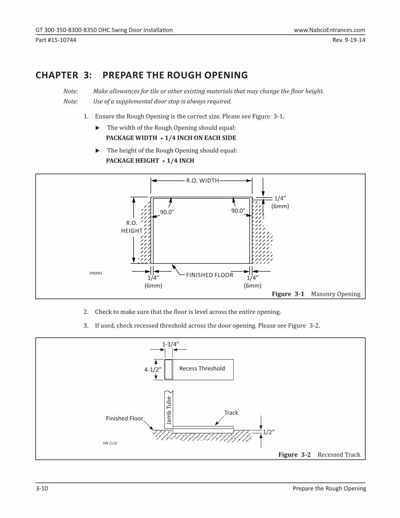
1.►Ensure the Rough Opening is the correct size. Please see Figure 3-1.
X The width of the Rough Opening should equal: PACKAGE WIDTH + 1/4 INCH ON EACH SIDE
X The height of the Rough Opening should equal: PACKAGE HEIGHT + 1/4 INCH
R.O. WIDTH
R.O. HEIGHT
90.0° 90.0°
1/4”(6mm)
FINISHED FLOORDN00811/4”
(6mm)
1/4”(6mm)
Figure 3-1 Masonry Opening
2.►Check to make sure that the floor is level across the entire opening.
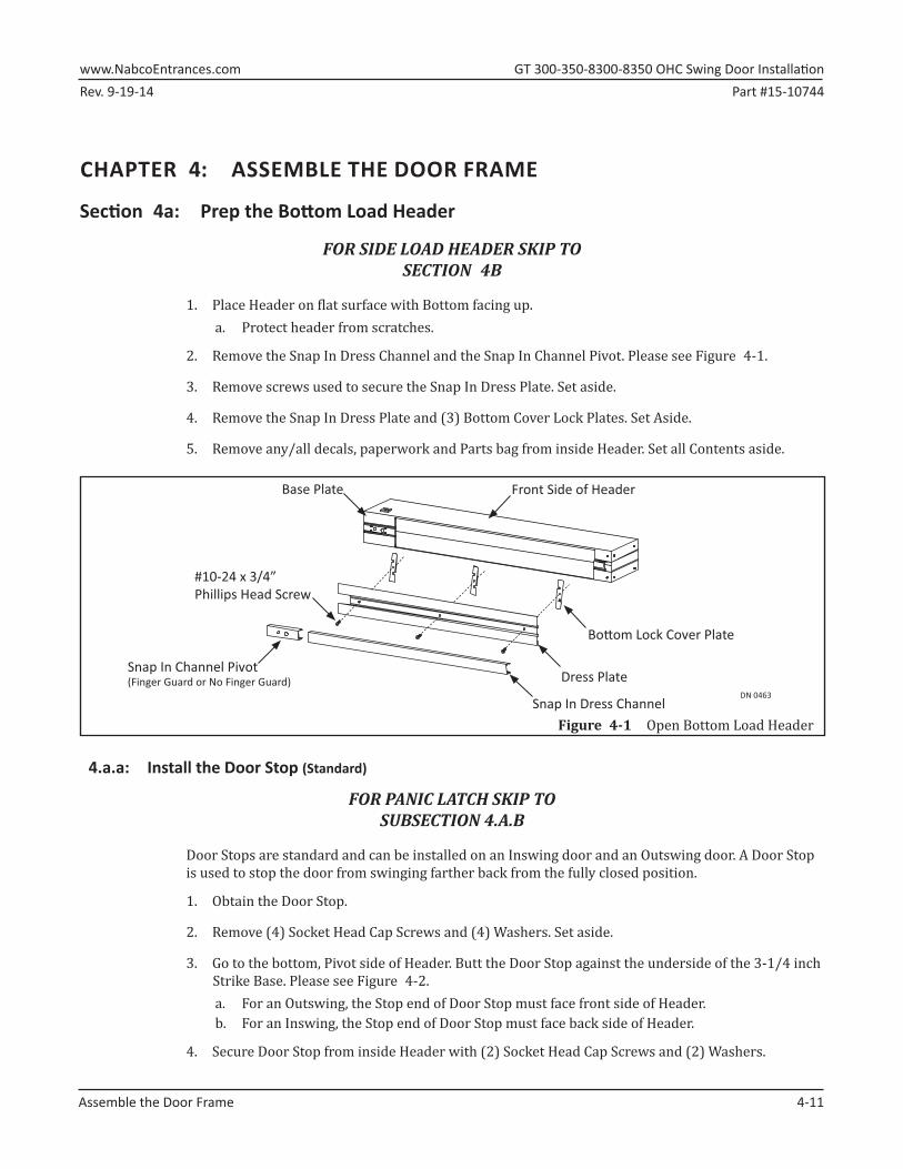
3.►If used, check recessed threshold across the door opening. Please see Figure 3-2.
Track
Jam
b Tu
be
1/2”
1-3/4”
DN 1110
Recess Threshold
Finished Floor
4-1/2”
Figure 3-2 Recessed Track
Rev. 9-19-14 Part #15-10744www.NabcoEntrances.com� GT�300-350-8300-8350�OHC�Swing�Door�Installation
Assemble�the�Door�Frame� 4-11
CHAPTER 4: ASSEMBLE THE DOOR FRAME
Section 4a: Prep the Bottom Load Header
FOR SIDE LOAD HEADER SKIP TO SECTION 4B
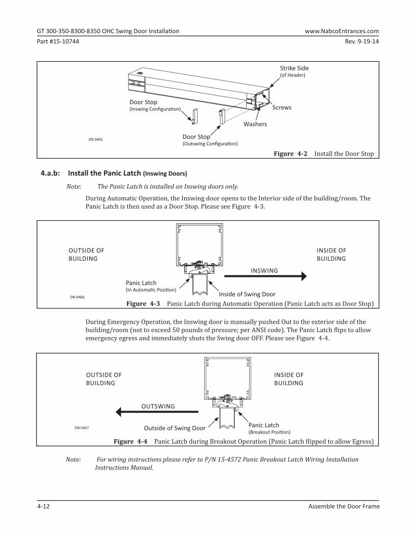
1.►Place Header on flat surface with Bottom facing up.a. Protect header from scratches.
2.►Remove the Snap In Dress Channel and the Snap In Channel Pivot. Please see Figure 4-1.
3.►Remove screws used to secure the Snap In Dress Plate. Set aside.
4.►Remove the Snap In Dress Plate and (3) Bottom Cover Lock Plates. Set Aside.
5.►Remove any/all decals, paperwork and Parts bag from inside Header. Set all Contents aside.
DN 0463
Base Plate Front Side of Header
#10-24 x 3/4”Phillips Head Screw
Snap In Dress Channel
Dress Plate
Bo� om Lock Cover Plate
Snap In Channel Pivot(Finger Guard or No Finger Guard)
Figure 4-1 Open Bottom Load Header
4.a.a: Install the Door Stop (Standard)
FOR PANIC LATCH SKIP TO SUBSECTION 4.A.B
Door Stops are standard and can be installed on an Inswing door and an Outswing door. A Door Stop is used to stop the door from swinging farther back from the fully closed position.
1.►Obtain the Door Stop.
2.►Remove (4) Socket Head Cap Screws and (4) Washers. Set aside.
3.►Go to the bottom, Pivot side of Header. Butt the Door Stop against the underside of the 3-1/4 inch Strike Base. Please see Figure 4-2.a. For an Outswing, the Stop end of Door Stop must face front side of Header.b. For an Inswing, the Stop end of Door Stop must face back side of Header.
4.►Secure Door Stop from inside Header with (2) Socket Head Cap Screws and (2) Washers.
GT�300-350-8300-8350�OHC�Swing�Door�Installation� www.NabcoEntrances.comPart #15-10744 Rev. 9-19-14
4-12� Assemble�the�Door�Frame
DN 0465
Screws
Door Stop(Outswing Confi gura� on)
Washers
Door Stop(Inswing Confi gura� on)
Strike Side(of Header)
Figure 4-2 Install the Door Stop
4.a.b: Install the Panic Latch (Inswing Doors)
Note: The Panic Latch is installed on Inswing doors only.
During Automatic Operation, the Inswing door opens to the Interior side of the building/room. The Panic Latch is then used as a Door Stop. Please see Figure 4-3.
Figure 4-3 Panic Latch during Automatic Operation (Panic Latch acts as Door Stop)DN 0466 Inside of Swing Door
Panic Latch(In Automa� c Posi� on)
OUTSIDE OF BUILDING
INSIDE OFBUILDING
INSWING
During Emergency Operation, the Inswing door is manually pushed Out to the exterior side of the building/room (not to exceed 50 pounds of pressure; per ANSI code). The Panic Latch flips to allow emergency egress and immediately shuts the Swing door OFF. Please see Figure 4-4.
. Figure 4-4 Panic Latch during Breakout Operation (Panic Latch flipped to allow Egress)
DN 0467 Panic Latch(Breakout Posi� on)
OUTSIDE OF BUILDING
INSIDE OFBUILDING
OUTSWING
Outside of Swing Door
Note: For wiring instructions please refer to P/N 15-4572 Panic Breakout Latch Wiring Installation Instructions Manual.
Rev. 9-19-14 Part #15-10744www.NabcoEntrances.com� GT�300-350-8300-8350�OHC�Swing�Door�Installation
Assemble�the�Door�Frame� 4-13
1.►Obtain the Panic Latch and (1) Decal. Set the Decal aside with all other Decals that were packed within Header. a. Decals are placed on Swing Door(s) after installation is complete.
2.►Remove (4) Socket Head Cap Screws and (4) Washers. Set aside.
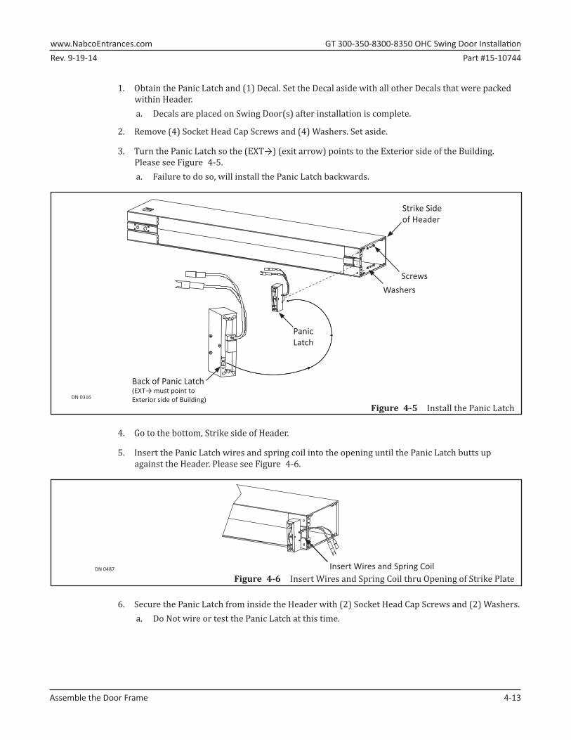
3.►Turn the Panic Latch so the (EXT→) (exit arrow) points to the Exterior side of the Building. Please see Figure 4-5.a. Failure to do so, will install the Panic Latch backwards.
DN 0316
EX
T
Back of Panic Latch(EXT→ must point toExterior side of Building)
PanicLatch
ScrewsWashers
Strike Sideof Header
Figure 4-5 Install the Panic Latch
4.►Go to the bottom, Strike side of Header.
5.►Insert the Panic Latch wires and spring coil into the opening until the Panic Latch butts up against the Header. Please see Figure 4-6.
DN 0487 Insert Wires and Spring Coil Figure 4-6 Insert Wires and Spring Coil thru Opening of Strike Plate
6.►Secure the Panic Latch from inside the Header with (2) Socket Head Cap Screws and (2) Washers. a. Do Not wire or test the Panic Latch at this time.
GT�300-350-8300-8350�OHC�Swing�Door�Installation� www.NabcoEntrances.comPart #15-10744 Rev. 9-19-14
4-14� Assemble�the�Door�Frame
Section 4b: Prep the Jamb Tubes
1.►Measure the full height of existing Swing door.
2.►Go to the bottom of each Jamb Tube, measure the full height calculation of Swing door plus: X 3/4 inch (19mm); if a Threshold is being installed X 1/4 inch (6.4mm); if a Threshold is not being installed
3.►Mark the measurement across the full width of each Jamb Tube.a. It is recommended to use a level for this step.
4.►Obtain (1) Jamb Drilling Template provided by NABCO.
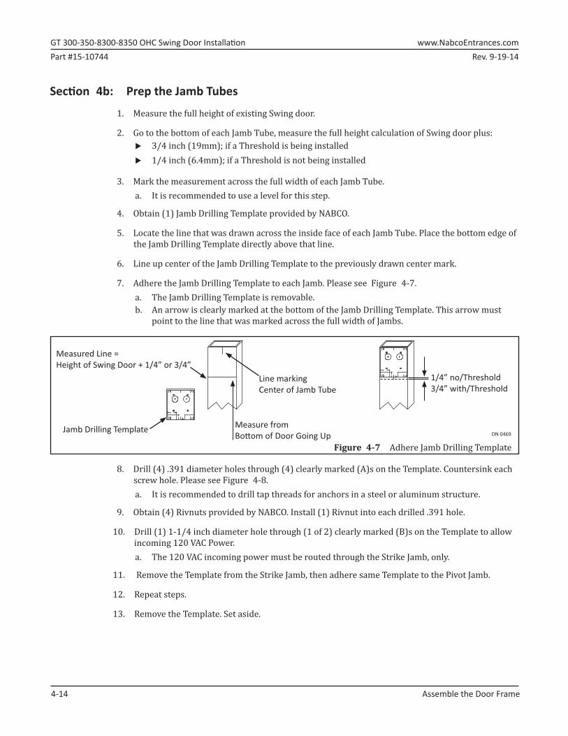
5.►Locate the line that was drawn across the inside face of each Jamb Tube. Place the bottom edge of the Jamb Drilling Template directly above that line.
6.►Line up center of the Jamb Drilling Template to the previously drawn center mark.
7.►Adhere the Jamb Drilling Template to each Jamb. Please see Figure 4-7.a. The Jamb Drilling Template is removable.b. An arrow is clearly marked at the bottom of the Jamb Drilling Template. This arrow must
point to the line that was marked across the full width of Jambs.
Figure 4-7 Adhere Jamb Drilling TemplateDN 0469
Line markingCenter of Jamb Tube
Measured Line = Height of Swing Door + 1/4” or 3/4”
Jamb Drilling Template
1/4” no/Threshold3/4” with/Threshold
Measure from Bo� om of Door Going Up
8.►Drill (4) .391 diameter holes through (4) clearly marked (A)s on the Template. Countersink each screw hole. Please see Figure 4-8.a. It is recommended to drill tap threads for anchors in a steel or aluminum structure.
9.►Obtain (4) Rivnuts provided by NABCO. Install (1) Rivnut into each drilled .391 hole.
10.►Drill (1) 1-1/4 inch diameter hole through (1 of 2) clearly marked (B)s on the Template to allow incoming 120 VAC Power. a. The 120 VAC incoming power must be routed through the Strike Jamb, only.
11.► Remove the Template from the Strike Jamb, then adhere same Template to the Pivot Jamb.
12.►Repeat steps.
13.►Remove the Template. Set aside.
Rev. 9-19-14 Part #15-10744www.NabcoEntrances.com� GT�300-350-8300-8350�OHC�Swing�Door�Installation
Assemble�the�Door�Frame� 4-15
Section 4c: Install the Header to Jamb Tubes
1.►Determine which Jamb tube is the Pivot Jamb and the Strike Jamb. a. Swing door pivots on side of Pivot Jamb.b. Swing door locks on side of Strike Jamb.
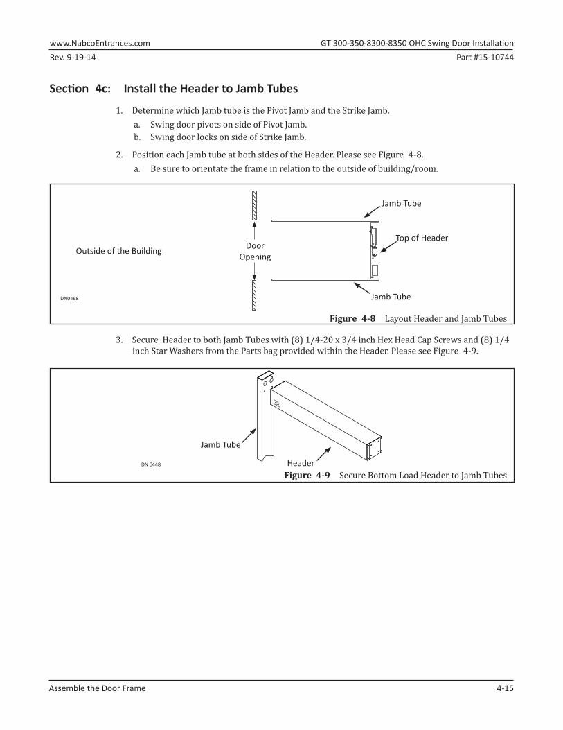
2.►Position each Jamb tube at both sides of the Header. Please see Figure 4-8.a. Be sure to orientate the frame in relation to the outside of building/room.
Figure 4-8 Layout Header and Jamb Tubes
DN0468 Jamb Tube
Top of HeaderDoor
Opening Outside of the Building
Jamb Tube
ON
3.►Secure Header to both Jamb Tubes with (8) 1/4-20 x 3/4 inch Hex Head Cap Screws and (8) 1/4 inch Star Washers from the Parts bag provided within the Header. Please see Figure 4-9.
Figure 4-9 Secure Bottom Load Header to Jamb TubesDN 0448
Jamb Tube
Header
GT�300-350-8300-8350�OHC�Swing�Door�Installation� www.NabcoEntrances.comPart #15-10744 Rev. 9-19-14
5-16� Install�Frame�to�Building
CHAPTER 5: INSTALL FRAME TO BUILDING
Section 5a: Secure Frame to Rough Opening
1.►Lift to position the assembled Frame into the rough opening.
2.►Insert all incoming wiring through the 1-1/4 inch hole located on the Strike side of Header.
Note: It is recommended for the Installer to use an Electrical Conduit to house all incoming 120 VAC wires.Note: Incoming 120 VAC Power wires must be pulled through the Strike end of Header for a single Swing door
or the middle of Header for a simultaneous pair Swing door.Note: All wiring must conform to standard wiring practices and be in accordance with national and local
electrical codes.
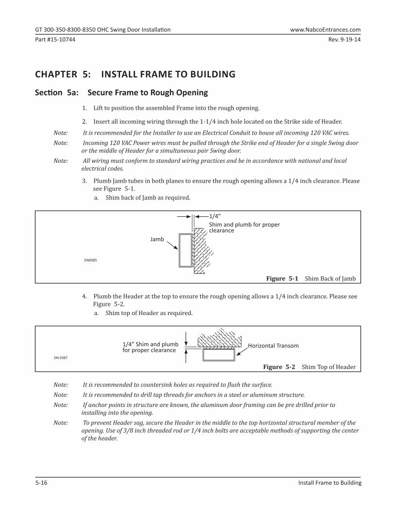
3.►Plumb Jamb tubes in both planes to ensure the rough opening allows a 1/4 inch clearance. Please see Figure 5-1.a. Shim back of Jamb as required.
Figure 5-1 Shim Back of Jamb
Shim�and�plumb�for�proper�clearance
1/4”
DN0085
Jamb
4.►Plumb the Header at the top to ensure the rough opening allows a 1/4 inch clearance. Please see Figure 5-2.a. Shim top of Header as required.
Figure 5-2 Shim Top of HeaderDN 0387
1/4”�Shim�and�plumb�for�proper�clearance
Horizontal Transom
Note: It is recommended to countersink holes as required to flush the surface.Note: It is recommended to drill tap threads for anchors in a steel or aluminum structure.Note: If anchor points in structure are known, the aluminum door framing can be pre drilled prior to
installing into the opening.Note: To prevent Header sag, secure the Header in the middle to the top horizontal structural member of the
opening. Use of 3/8 inch threaded rod or 1/4 inch bolts are acceptable methods of supporting the center of the header.
Rev. 9-19-14 Part #15-10744www.NabcoEntrances.com� GT�300-350-8300-8350�OHC�Swing�Door�Installation
Install�Frame�to�Building� 5-17
5.a.a: Anchor Placement for Header
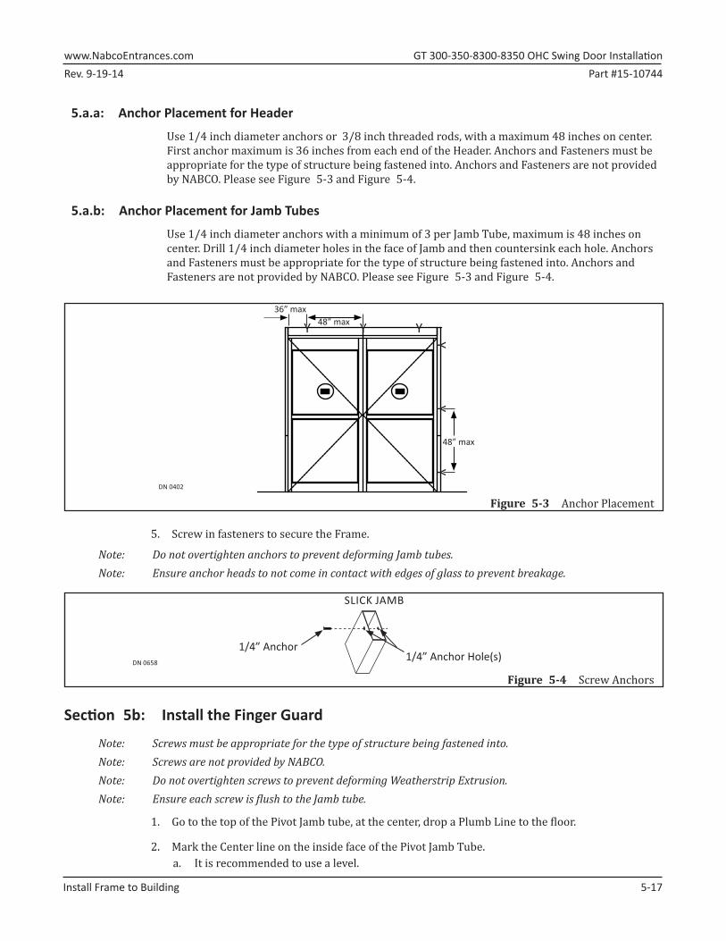
Use 1/4 inch diameter anchors or 3/8 inch threaded rods, with a maximum 48 inches on center. First anchor maximum is 36 inches from each end of the Header. Anchors and Fasteners must be appropriate for the type of structure being fastened into. Anchors and Fasteners are not provided by NABCO. Please see Figure 5-3 and Figure 5-4.
5.a.b: Anchor Placement for Jamb Tubes
Use 1/4 inch diameter anchors with a minimum of 3 per Jamb Tube, maximum is 48 inches on center. Drill 1/4 inch diameter holes in the face of Jamb and then countersink each hole. Anchors and Fasteners must be appropriate for the type of structure being fastened into. Anchors and Fasteners are not provided by NABCO. Please see Figure 5-3 and Figure 5-4.
Figure 5-3 Anchor PlacementDN�0402
36”�max48”�max
48”�max
Y Y Y
YY
Y
5.►Screw in fasteners to secure the Frame.
Note: Do not overtighten anchors to prevent deforming Jamb tubes.Note: Ensure anchor heads to not come in contact with edges of glass to prevent breakage.
Figure 5-4 Screw AnchorsDN 0658
SLICK JAMB
1/4” Anchor1/4” Anchor Hole(s)
Section 5b: Install the Finger Guard
Note: Screws must be appropriate for the type of structure being fastened into.Note: Screws are not provided by NABCO.Note: Do not overtighten screws to prevent deforming Weatherstrip Extrusion.Note: Ensure each screw is flush to the Jamb tube.
1.►Go to the top of the Pivot Jamb tube, at the center, drop a Plumb Line to the floor.
2.►Mark the Center line on the inside face of the Pivot Jamb Tube. a. It is recommended to use a level.
GT�300-350-8300-8350�OHC�Swing�Door�Installation� www.NabcoEntrances.comPart #15-10744 Rev. 9-19-14
5-18� Install�Frame�to�Building
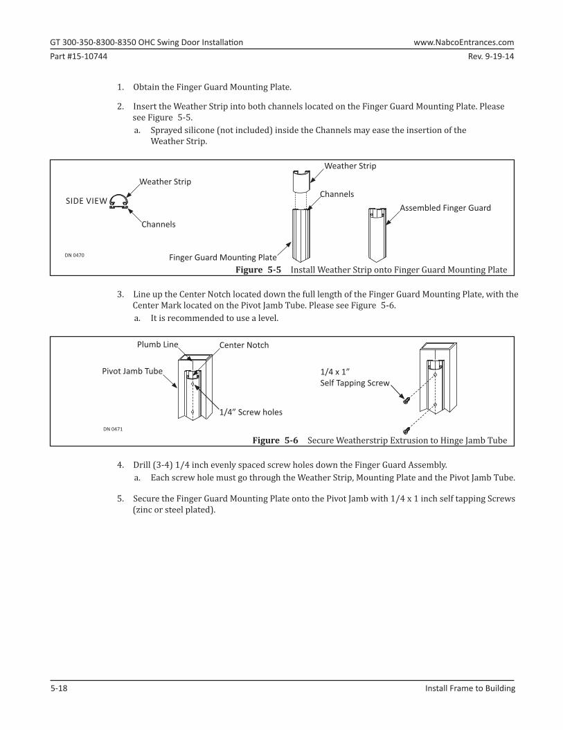
1.►Obtain the Finger Guard Mounting Plate.
2.►Insert the Weather Strip into both channels located on the Finger Guard Mounting Plate. Please see Figure 5-5.a. Sprayed silicone (not included) inside the Channels may ease the insertion of the
Weather Strip.
Figure 5-5 Install Weather Strip onto Finger Guard Mounting Plate
DN 0470
Weather Strip
ChannelsWeather Strip
Channels
Finger Guard Moun� ng Plate
SIDE VIEWAssembled Finger Guard
3.►Line up the Center Notch located down the full length of the Finger Guard Mounting Plate, with the Center Mark located on the Pivot Jamb Tube. Please see Figure 5-6.a. It is recommended to use a level.
Figure 5-6 Secure Weatherstrip Extrusion to Hinge Jamb TubeDN 0471
Plumb Line
1/4” Screw holes
1/4 x 1”Self Tapping Screw
Pivot Jamb Tube
Center Notch
4.►Drill (3-4) 1/4 inch evenly spaced screw holes down the Finger Guard Assembly.a. Each screw hole must go through the Weather Strip, Mounting Plate and the Pivot Jamb Tube.
5.►Secure the Finger Guard Mounting Plate onto the Pivot Jamb with 1/4 x 1 inch self tapping Screws (zinc or steel plated).
Rev. 9-19-14 Part #15-10744www.NabcoEntrances.com� GT�300-350-8300-8350�OHC�Swing�Door�Installation
Install�Bottom�Load�Components� 6-19
CHAPTER 6: INSTALL BOTTOM LOAD COMPONENTSFOR SIDE LOAD HEADER SKIP TO
CHAPTER 7
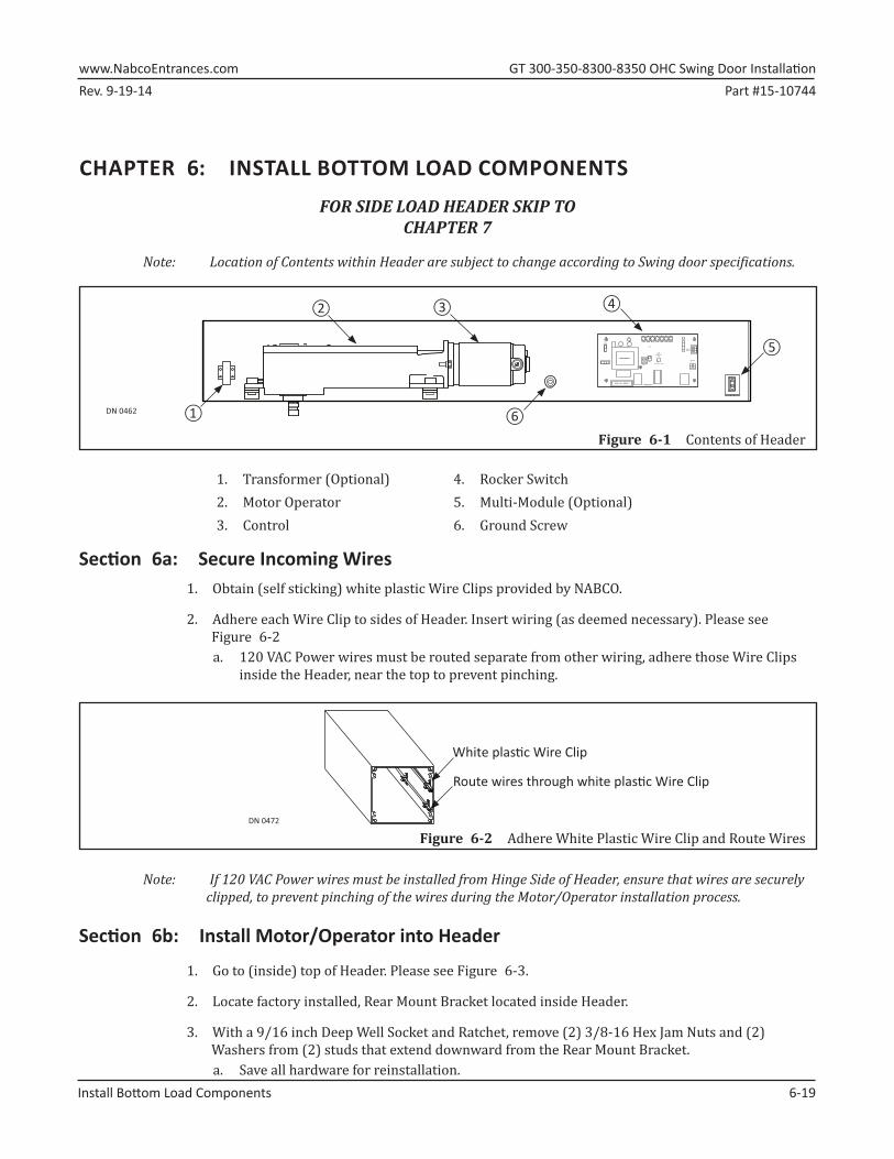
Note: Location of Contents within Header are subject to change according to Swing door specifications.
DN 0462 ①
② ③ ④
⑤
⑥
ON
SIGNA L INPU T
MOTOR J5
LESS SENSITIV E
R28
CURRENT LIMIT
LED
SW2
SW1
CLOSELCHKTDPGTDASBCH KOPENSTOP
R2 R3 R4 R5 R6 R7 R8
MAGNU M IV
TRANSFORME R
FUSE 1:3A 120/240
AUX PWR
FUSE 2; 0.5 A 24 VAC
1. Transformer (Optional) 4. Rocker Switch2. Motor Operator 5. Multi-Module (Optional)3. Control 6. Ground Screw
Section 6a: Secure Incoming Wires1.►Obtain (self sticking) white plastic Wire Clips provided by NABCO.
2.►Adhere each Wire Clip to sides of Header. Insert wiring (as deemed necessary). Please see Figure 6-2a. 120 VAC Power wires must be routed separate from other wiring, adhere those Wire Clips
inside the Header, near the top to prevent pinching.
DN 0472
Route wires through white plas� c Wire Clip
White plas� c Wire Clip
Figure 6-2 Adhere White Plastic Wire Clip and Route Wires
Note: If 120 VAC Power wires must be installed from Hinge Side of Header, ensure that wires are securely clipped, to prevent pinching of the wires during the Motor/Operator installation process.
Section 6b: Install Motor/Operator into Header
1.►Go to (inside) top of Header. Please see Figure 6-3.
2.►Locate factory installed, Rear Mount Bracket located inside Header.
3.►With a 9/16 inch Deep Well Socket and Ratchet, remove (2) 3/8-16 Hex Jam Nuts and (2) Washers from (2) studs that extend downward from the Rear Mount Bracket.a. Save all hardware for reinstallation.
Figure 6-1 Contents of Header
GT�300-350-8300-8350�OHC�Swing�Door�Installation� www.NabcoEntrances.comPart #15-10744 Rev. 9-19-14
6-20� Install�Bottom�Load�Components�
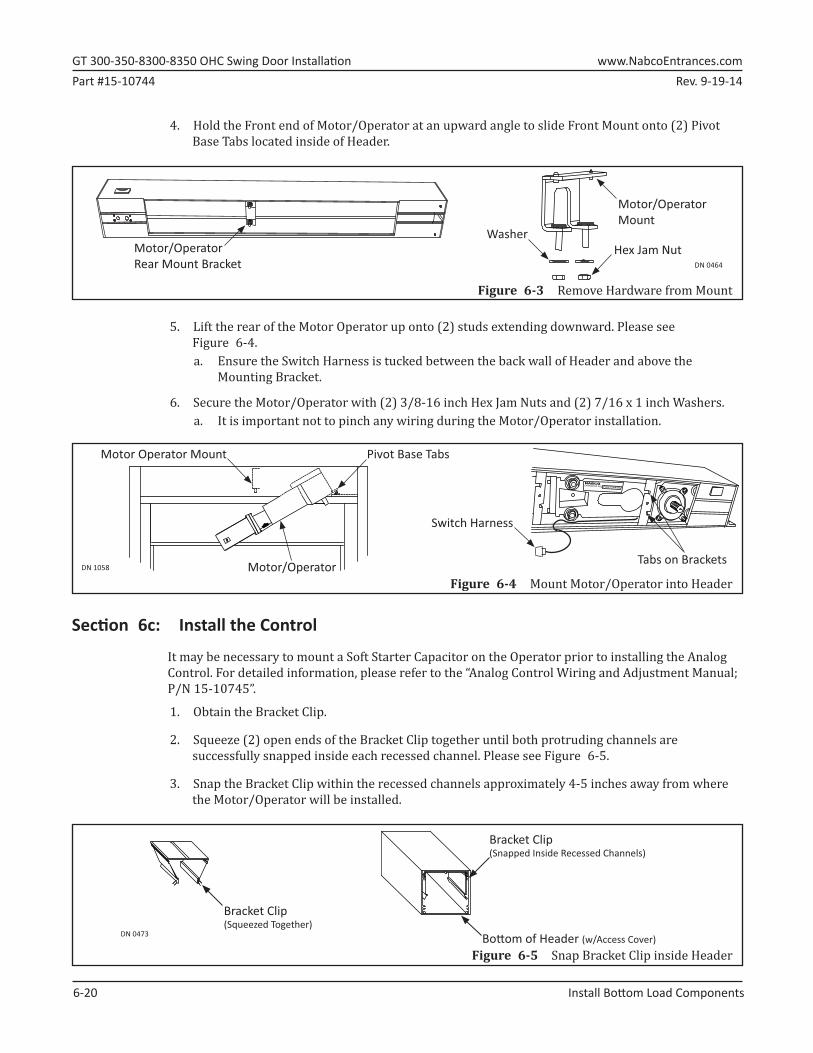
4.►Hold the Front end of Motor/Operator at an upward angle to slide Front Mount onto (2) Pivot Base Tabs located inside of Header.
DN 0464
Motor/OperatorRear Mount Bracket
WasherHex Jam Nut
Motor/OperatorMount
Figure 6-3 Remove Hardware from Mount
5.►Lift the rear of the Motor Operator up onto (2) studs extending downward. Please see Figure 6-4.a. Ensure the Switch Harness is tucked between the back wall of Header and above the
Mounting Bracket.
6.►Secure the Motor/Operator with (2) 3/8-16 inch Hex Jam Nuts and (2) 7/16 x 1 inch Washers.a. It is important not to pinch any wiring during the Motor/Operator installation.
Figure 6-4 Mount Motor/Operator into HeaderDN 1058
Pivot Base TabsMotor Operator Mount
Motor/Operator
ENTRANCES INC. R3J724456NABCO
Tabs on Brackets
Switch Harness
Section 6c: Install the Control
It may be necessary to mount a Soft Starter Capacitor on the Operator prior to installing the Analog Control. For detailed information, please refer to the “Analog Control Wiring and Adjustment Manual; P/N 15-10745”.
1.►Obtain the Bracket Clip.
2.►Squeeze (2) open ends of the Bracket Clip together until both protruding channels are successfully snapped inside each recessed channel. Please see Figure 6-5.
3.►Snap the Bracket Clip within the recessed channels approximately 4-5 inches away from where the Motor/Operator will be installed.
Figure 6-5 Snap Bracket Clip inside Header
DN 0473
Bracket Clip (Squeezed Together)
Bracket Clip (Snapped Inside Recessed Channels)
Bo� om of Header (w/Access Cover)
Rev. 9-19-14 Part #15-10744www.NabcoEntrances.com� GT�300-350-8300-8350�OHC�Swing�Door�Installation
Install�Bottom�Load�Components� 6-21
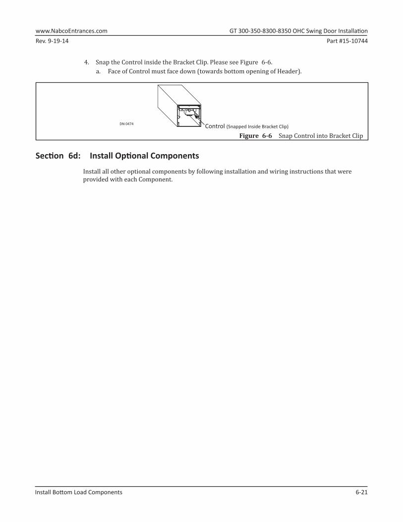
4.►Snap the Control inside the Bracket Clip. Please see Figure 6-6.a. Face of Control must face down (towards bottom opening of Header).
Figure 6-6 Snap Control into Bracket Clip
DN 0474 Control (Snapped Inside Bracket Clip)
Section 6d: Install Optional Components
Install all other optional components by following installation and wiring instructions that were provided with each Component.
GT�300-350-8300-8350�OHC�Swing�Door�Installation� www.NabcoEntrances.comPart #15-10538 Rev. 9-19-14
7-22� 110�VAC�General�Wiring
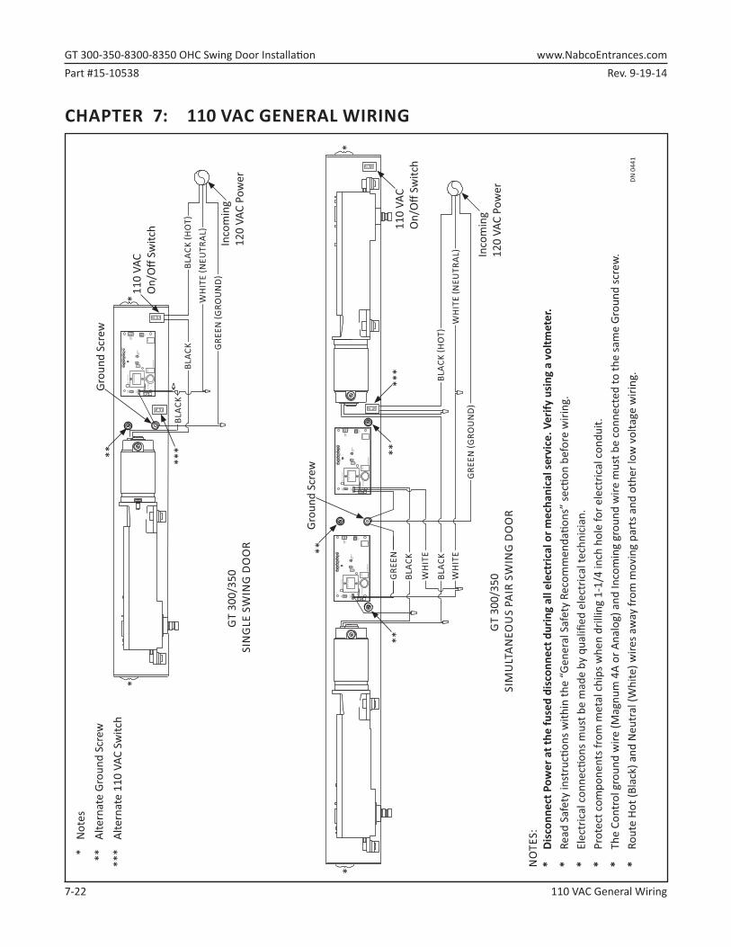
CHAPTER 7: 110 VAC GENERAL WIRING
LED
TRA
NS
FOR
ME
R
OFF
12
AU
XP
WR
4
J2
3
J5
AC
IN F2
SW
2S
W1
F1
RE
LAY
RE
LAY
J4
TDA
S
SIG
NA
LIN
PU
T
TDP
G LCH
KCLO
SE
Fuse
1: 0
.5A
24
VAC
STO
P OP
ENB
CH
K
CU
RR
EN
TLI
MIT
MO
TOR
J1R
28
MA
GN
UM
4A
Fuse
2: 5
A 1
20/2
40
Cap
acito
rM
OV
LED
TRA
NS
FOR
ME
R
OFF
12
AU
XP
WR
4
J2
3
J5
AC
IN F2
SW
2S
W1
F1
RE
LAY
RE
LAY
J4
TDA
S
SIG
NA
LIN
PU
T
TDP
G LCH
KCLO
SE
Fuse
1: 0
.5A
24
VAC
STO
P OP
ENB
CH
K
CU
RR
EN
TLI
MIT
MO
TOR
J1R
28
MA
GN
UM
4A
Fuse
2: 5
A 1
20/2
40
Cap
acito
rM
OV
DN 0
441
Inco
min
g12
0 VA
C Po
wer
GRE
EN �G
ROU
ND
�
Grou
nd S
crew
**11
0 VA
CO
n/O
ff Sw
itch
**
*N
otes
**Al
tern
ate
Grou
nd S
crew
***
Alte
rnat
e 11
0 VA
C Sw
itch
*
***
NO
TES:
* Di
scon
nect
Pow
er a
t the
fuse
d di
scon
nect
dur
ing
all e
lect
rical
or m
echa
nica
l ser
vice
. Ver
ify u
sing
a v
oltm
eter
. *
Read
Saf
ety
inst
ruc�
ons
with
in th
e “G
ener
al S
afet
y Re
com
men
da� o
ns”
sec�
on
befo
re w
iring
.*
Elec
tric
al c
onne
c� o
ns m
ust b
e m
ade
by q
ualifi
ed
elec
tric
al te
chni
cian
.*
Prot
ect c
ompo
nent
s fro
m m
etal
chi
ps w
hen
drill
ing
1-1/
4 in
ch h
ole
for e
lect
rical
con
duit.
*
The
Cont
rol g
roun
d w
ire (M
agnu
m 4
A or
Ana
log)
and
Inco
min
g gr
ound
wire
mus
t be
conn
ecte
d to
the
sam
e Gr
ound
scre
w.
* Ro
ute
Hot (
Blac
k) a
nd N
eutr
al (W
hite
) wire
s aw
ay fr
om m
ovin
g pa
rts a
nd o
ther
low
vol
tage
wiri
ng.
**
*
WH
ITE
�NEU
TRAL
� BL
ACK
�HO
T�
WH
ITE
GRE
ENBL
ACK
BLAC
K
WH
ITE
Grou
nd S
crew
**
110
VAC
On/
Off
Switc
h
Inco
min
g12
0 VA
C Po
wer
WH
ITE
�NEU
TRAL
�
***
**
BLAC
K
GRE
EN �G
ROU
ND
�G
T 30
0/35
0 S
ING
LE S
WIN
G D
OO
R
BLAC
K
GT
300/
350
SIM
ULT
ANEO
US
PAIR
SW
ING
DO
OR
ON
OFF
LED
TRA
NS
FOR
ME
R
OFF
12
AU
XP
WR
4
J2
3
J5
AC
IN F2
SW
2S
W1
F1
RE
LAY
RE
LAY
J4
TDA
S
SIG
NA
LIN
PU
T
TDP
G LCH
KCLO
SE
Fuse
1: 0
.5A
24
VAC
STO
P OP
ENB
CH
K
CU
RR
EN
TLI
MIT
MO
TOR
J1R
28
MA
GN
UM
4A
Fuse
2: 5
A 1
20/2
40
Cap
acito
rM
OV
ON
OFF
ON
OFF
ON
OFF
BLAC
K �H
OT�
Rev. 9-19-14 Part #15-10744www.NabcoEntrances.com� GT�300-350/-300-8350�OHC�Swing�Door�Installation
Install�the�Floor�Pivot� 8-23
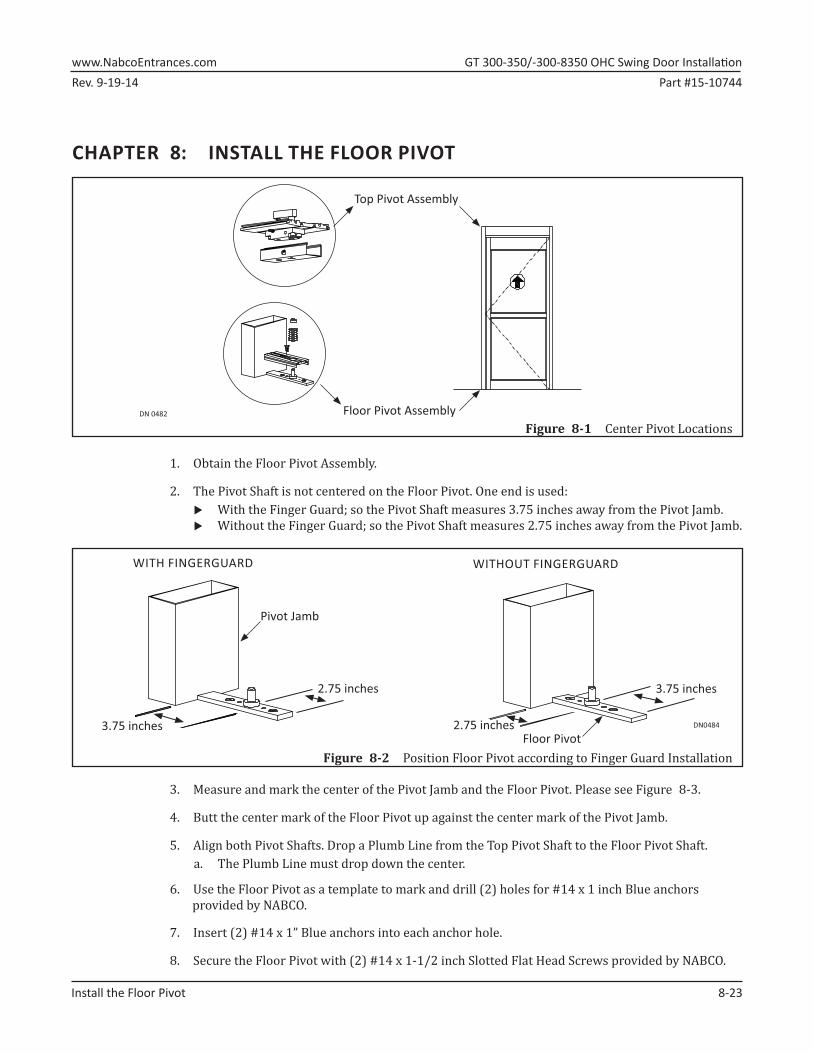
CHAPTER 8: INSTALL THE FLOOR PIVOT
DN 0482 Floor Pivot Assembly
Top Pivot Assembly
Figure 8-1 Center Pivot Locations
1.►Obtain the Floor Pivot Assembly.
2.►The Pivot Shaft is not centered on the Floor Pivot. One end is used: X With the Finger Guard; so the Pivot Shaft measures 3.75 inches away from the Pivot Jamb. X Without the Finger Guard; so the Pivot Shaft measures 2.75 inches away from the Pivot Jamb.
DN04843.75 inches 2.75 inches
2.75 inches 3.75 inches
Pivot Jamb
Floor Pivot
WITH FINGERGUARD WITHOUT FINGERGUARD
Figure 8-2 Position Floor Pivot according to Finger Guard Installation
3.►Measure and mark the center of the Pivot Jamb and the Floor Pivot. Please see Figure 8-3.
4.►Butt the center mark of the Floor Pivot up against the center mark of the Pivot Jamb.
5.►Align both Pivot Shafts. Drop a Plumb Line from the Top Pivot Shaft to the Floor Pivot Shaft.a. The Plumb Line must drop down the center.
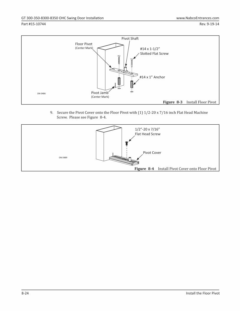
6.►Use the Floor Pivot as a template to mark and drill (2) holes for #14 x 1 inch Blue anchors provided by NABCO.
7.►Insert (2) #14 x 1” Blue anchors into each anchor hole.
8.►Secure the Floor Pivot with (2) #14 x 1-1/2 inch Slotted Flat Head Screws provided by NABCO.
GT�300-350-8300-8350�OHC�Swing�Door�Installation� www.NabcoEntrances.comPart #15-10744 Rev. 9-19-14
8-24� Install�the�Floor�Pivot
DN 0486
Pivot Sha�
#14 x 1-1/2”Slo� ed Flat Screw
#14 x 1” Anchor
Pivot Jamb(Center Mark)
Floor Pivot(Center Mark)
Figure 8-3 Install Floor Pivot
9.►Secure the Pivot Cover onto the Floor Pivot with (1) 1/2-20 x 7/16 inch Flat Head Machine Screw. Please see Figure 8-4.
DN 0489
1/2”-20 x 7/16”Flat Head Screw
Pivot Cover
Figure 8-4 Install Pivot Cover onto Floor Pivot
Rev. 9-19-14 Part #15-10744www.NabcoEntrances.com� GT�300-350-8300-8350�OHC�Swing�Door�Installation
Install�the�Threshold� 9-23
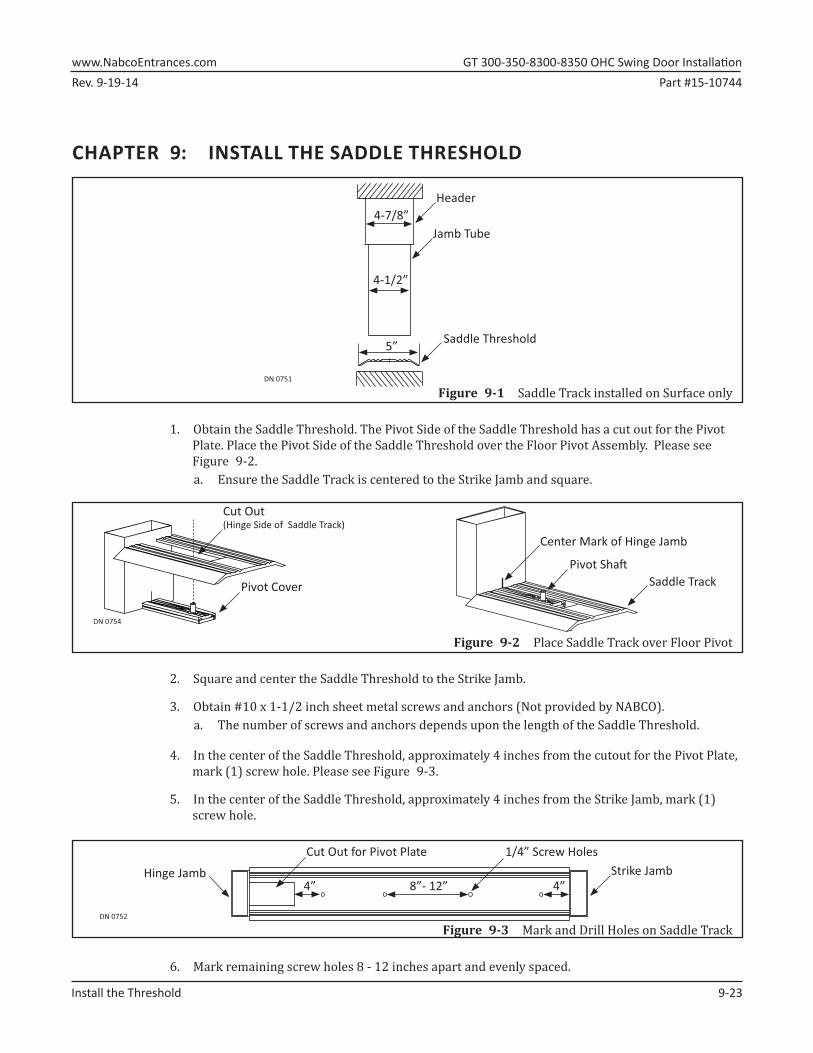
CHAPTER 9: INSTALL THE SADDLE THRESHOLD
Figure 9-1 Saddle Track installed on Surface onlyDN 0751
Header4-7/8”
4-1/2”
Jamb Tube
Saddle Threshold5”
1.►Obtain the Saddle Threshold. The Pivot Side of the Saddle Threshold has a cut out for the Pivot Plate. Place the Pivot Side of the Saddle Threshold over the Floor Pivot Assembly. Please see Figure 9-2.a. Ensure the Saddle Track is centered to the Strike Jamb and square.
Figure 9-2 Place Saddle Track over Floor Pivot
DN 0754
Saddle TrackPivot Cover
Cut Out (Hinge Side of Saddle Track)
Pivot Sha�
Center Mark of Hinge Jamb
2.►Square and center the Saddle Threshold to the Strike Jamb.
3.►Obtain #10 x 1-1/2 inch sheet metal screws and anchors (Not provided by NABCO).a. The number of screws and anchors depends upon the length of the Saddle Threshold.
4.►In the center of the Saddle Threshold, approximately 4 inches from the cutout for the Pivot Plate, mark (1) screw hole. Please see Figure 9-3.
5.►In the center of the Saddle Threshold, approximately 4 inches from the Strike Jamb, mark (1) screw hole.
Figure 9-3 Mark and Drill Holes on Saddle TrackDN 0752
Strike Jamb1/4” Screw HolesCut Out for Pivot Plate
4” 4”8”- 12”Hinge Jamb
6.►Mark remaining screw holes 8 - 12 inches apart and evenly spaced.
GT�300-350-8300-8350�OHC�Swing�Door�Installation� www.NabcoEntrances.comPart #15-10744 Rev. 9-19-14
9-24� Install�the�Threshold
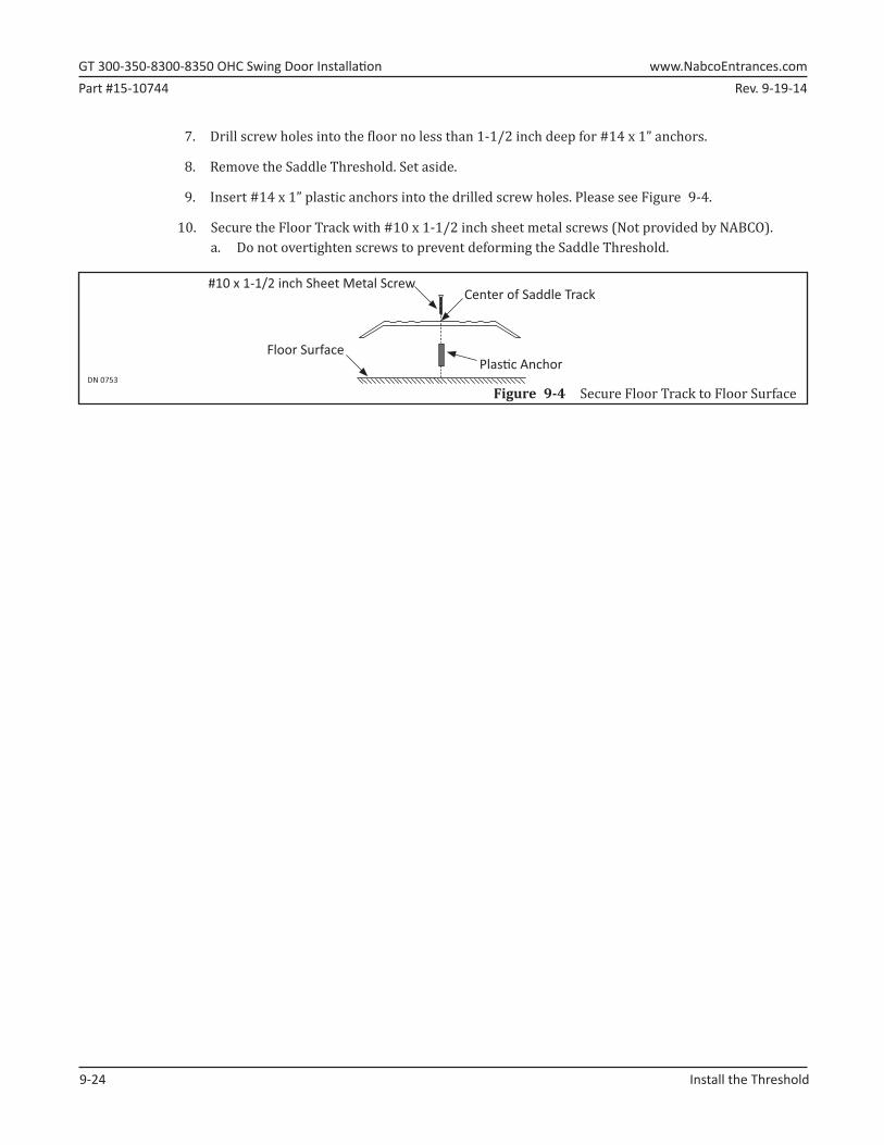
7.►Drill screw holes into the floor no less than 1-1/2 inch deep for #14 x 1” anchors.
8.►Remove the Saddle Threshold. Set aside.
9.►Insert #14 x 1” plastic anchors into the drilled screw holes. Please see Figure 9-4.
10.►Secure the Floor Track with #10 x 1-1/2 inch sheet metal screws (Not provided by NABCO).a. Do not overtighten screws to prevent deforming the Saddle Threshold.
Figure 9-4 Secure Floor Track to Floor SurfaceDN 0753
Center of Saddle Track#10 x 1-1/2 inch Sheet Metal Screw
Floor SurfacePlas� c Anchor
Rev. 9-19-14 Part #15-10744www.NabcoEntrances.com� GT�300-350-8300-8350�OHC�Swing�Door�Installation
Install�the�Swing�Door� 10-23
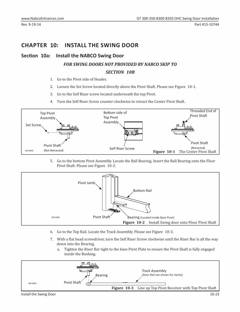
CHAPTER 10: INSTALL THE SWING DOOR
Section 10a: Install the NABCO Swing DoorFOR SWING DOORS NOT PROVIDED BY NABCO SKIP TO
SECTION 10B1.►Go to the Pivot side of Header.
2.►Loosen the Set Screw located directly above the Pivot Shaft. Please see Figure 10-1.
3.►Go to the Self Riser screw located underneath the top Pivot.
4.►Turn the Self Riser Screw counter-clockwise to retract the Center Pivot Shaft.
DN 0493
Pivot Sha� (Not Retracted)
Pivot Sha� (Retracted)
Threaded End ofPivot Sha�
Set Screw
Self Riser Screw
Bo� om side of Top PivotAssembly
Top PivotAssembly
Figure 10-1 The Center Pivot Shaft
5.►Go to the bottom Pivot Assembly. Locate the Ball Bearing. Insert the Ball Bearing onto the Floor Pivot Shaft. Please see Figure 10-2.
Figure 10-2 Install Swing door onto Floor Pivot ShaftDN 0495
Pivot Jamb
Bo� om Rail
Bearing (Located inside Base Pivot)Pivot Sha�
6.►Go to the Top Rail. Locate the Track Assembly. Please see Figure 10-3.
7.►With a flat head screwdriver, turn the Self Riser Screw clockwise until the Riser Bar is all the way down into the Bearing. a. Tighten the Riser Bar tight to the base Pivot Plate to ensure the Pivot Shaft is fully engaged
inside the Bushing.
Figure 10-3 Line up Top Pivot Receiver with Top Pivot ShaftDN 0492
BearingTrack Assembly(Door Rail not shown for clarity)
Pivot Sha�
GT�300-350-8300-8350�OHC�Swing�Door�Installation� www.NabcoEntrances.comPart #15-10744 Rev. 9-19-14
10-24� Install�the�Swing�Door
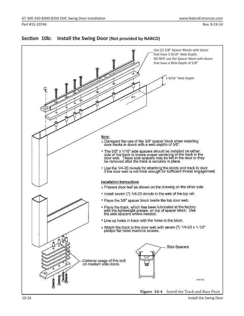
Section 10b: Install the Swing Door (Not provided by NABCO)
DN0756
Use (2) 3/8” Spacer Blocks with doorsthat have 1-9/16” Web Depth.DO NOT use the Spacer Block with doors that have a Web Depth of 5/8”
1-9/16” Web Depth
Figure 10-4 Install the Track and Base Pivot
Rev. 9-19-14 Part #15-10744www.NabcoEntrances.com� GT�300-350-8300-8350�OHC�Swing�Door�Installation
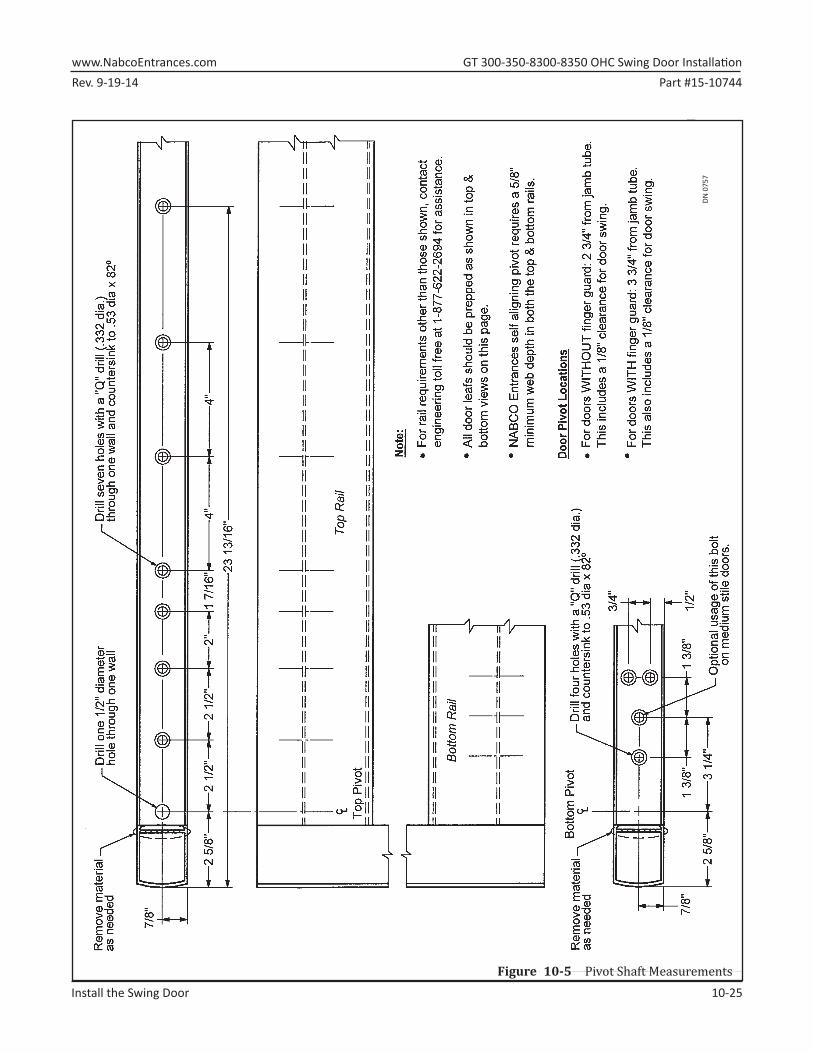
Install�the�Swing�Door� 10-25
DN 0
757
Figure 10-5 Pivot Shaft Measurements
GT�300-350-8300-8350�OHC�Swing�Door�Installation� www.NabcoEntrances.comPart #15-10744 Rev. 9-19-14
10-26� Install�the�Swing�Door
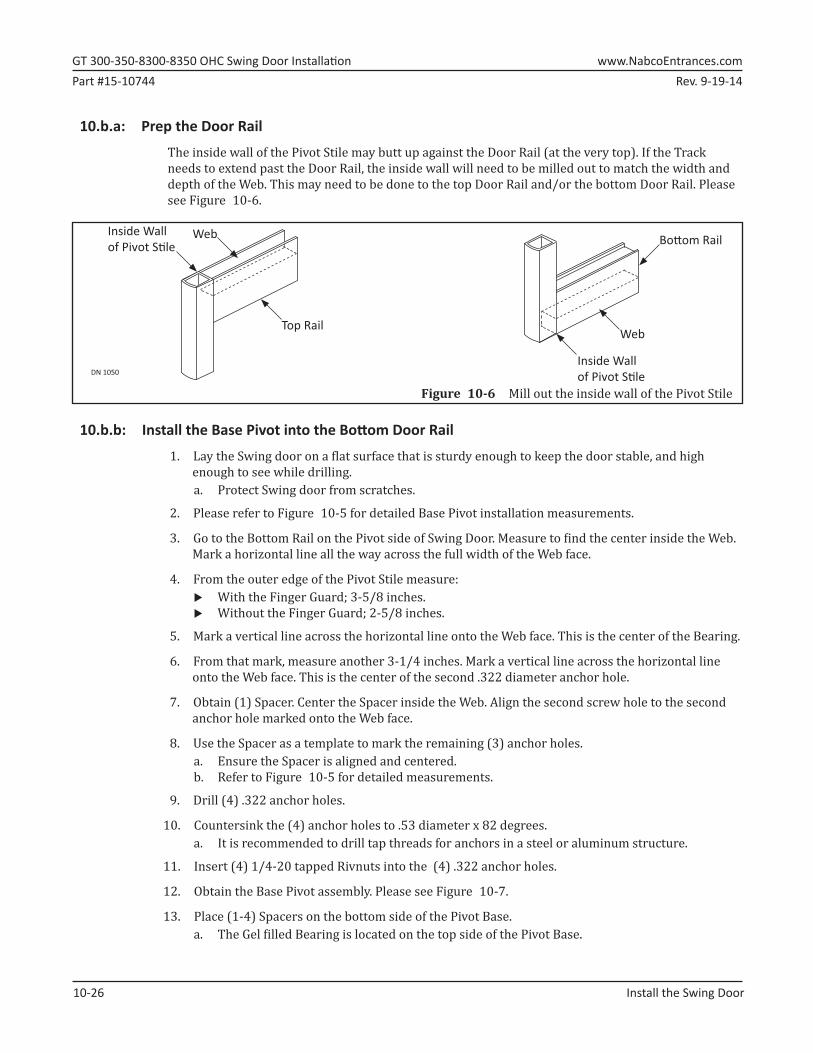
10.b.a: Prep the Door Rail
The inside wall of the Pivot Stile may butt up against the Door Rail (at the very top). If the Track needs to extend past the Door Rail, the inside wall will need to be milled out to match the width and depth of the Web. This may need to be done to the top Door Rail and/or the bottom Door Rail. Please see Figure 10-6.
DN 1050
Inside Wallof Pivot S� le
Top Rail
Bo� om RailWeb
Web
Inside Wallof Pivot S� le
Figure 10-6 Mill out the inside wall of the Pivot Stile
10.b.b: Install the Base Pivot into the Bottom Door Rail
1.►Lay the Swing door on a flat surface that is sturdy enough to keep the door stable, and high enough to see while drilling. a. Protect Swing door from scratches.
2.►Please refer to Figure 10-5 for detailed Base Pivot installation measurements.
3.►Go to the Bottom Rail on the Pivot side of Swing Door. Measure to find the center inside the Web. Mark a horizontal line all the way across the full width of the Web face.
4.►From the outer edge of the Pivot Stile measure: X With the Finger Guard; 3-5/8 inches. X Without the Finger Guard; 2-5/8 inches.
5.►Mark a vertical line across the horizontal line onto the Web face. This is the center of the Bearing.
6.►From that mark, measure another 3-1/4 inches. Mark a vertical line across the horizontal line onto the Web face. This is the center of the second .322 diameter anchor hole.
7.►Obtain (1) Spacer. Center the Spacer inside the Web. Align the second screw hole to the second anchor hole marked onto the Web face.
8.►Use the Spacer as a template to mark the remaining (3) anchor holes.a. Ensure the Spacer is aligned and centered.b. Refer to Figure 10-5 for detailed measurements.
9.►Drill (4) .322 anchor holes.
10.►Countersink the (4) anchor holes to .53 diameter x 82 degrees.a. It is recommended to drill tap threads for anchors in a steel or aluminum structure.
11.►Insert (4) 1/4-20 tapped Rivnuts into the (4) .322 anchor holes.
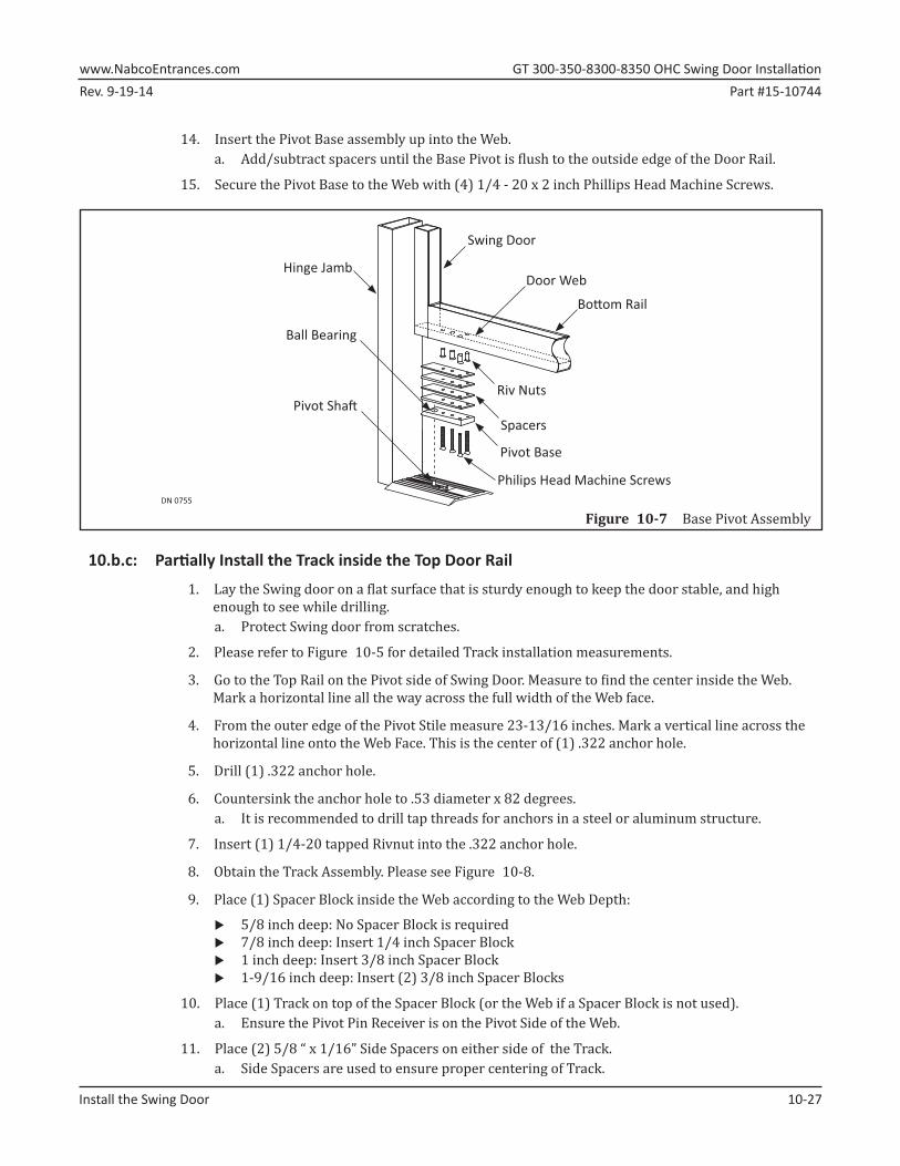
12.►Obtain the Base Pivot assembly. Please see Figure 10-7.
13.►Place (1-4) Spacers on the bottom side of the Pivot Base.a. The Gel filled Bearing is located on the top side of the Pivot Base.
Rev. 9-19-14 Part #15-10744www.NabcoEntrances.com� GT�300-350-8300-8350�OHC�Swing�Door�Installation
Install�the�Swing�Door� 10-27
14.►Insert the Pivot Base assembly up into the Web. a. Add/subtract spacers until the Base Pivot is flush to the outside edge of the Door Rail.
15.►Secure the Pivot Base to the Web with (4) 1/4 - 20 x 2 inch Phillips Head Machine Screws.
DN 0755
Hinge Jamb
Swing Door
Riv Nuts
Spacers
Pivot Base
Philips Head Machine Screws
Ball Bearing
Pivot Sha�
Door Web
Bo� om Rail
Figure 10-7 Base Pivot Assembly
10.b.c: Partially Install the Track inside the Top Door Rail
1.►Lay the Swing door on a flat surface that is sturdy enough to keep the door stable, and high enough to see while drilling. a. Protect Swing door from scratches.
2.►Please refer to Figure 10-5 for detailed Track installation measurements.
3.►Go to the Top Rail on the Pivot side of Swing Door. Measure to find the center inside the Web. Mark a horizontal line all the way across the full width of the Web face.
4.►From the outer edge of the Pivot Stile measure 23-13/16 inches. Mark a vertical line across the horizontal line onto the Web Face. This is the center of (1) .322 anchor hole.
5.►Drill (1) .322 anchor hole.
6.►Countersink the anchor hole to .53 diameter x 82 degrees.a. It is recommended to drill tap threads for anchors in a steel or aluminum structure.
7.►Insert (1) 1/4-20 tapped Rivnut into the .322 anchor hole.
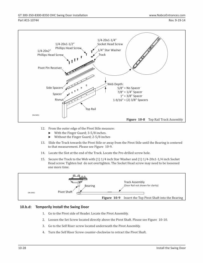
8.►Obtain the Track Assembly. Please see Figure 10-8.
9.►Place (1) Spacer Block inside the Web according to the Web Depth:
X 5/8 inch deep: No Spacer Block is required X 7/8 inch deep: Insert 1/4 inch Spacer Block X 1 inch deep: Insert 3/8 inch Spacer Block X 1-9/16 inch deep: Insert (2) 3/8 inch Spacer Blocks
10.►Place (1) Track on top of the Spacer Block (or the Web if a Spacer Block is not used).a. Ensure the Pivot Pin Receiver is on the Pivot Side of the Web.
11.►Place (2) 5/8 “ x 1/16” Side Spacers on either side of the Track.a. Side Spacers are used to ensure proper centering of Track.
GT�300-350-8300-8350�OHC�Swing�Door�Installation� www.NabcoEntrances.comPart #15-10744 Rev. 9-19-14
10-28� Install�the�Swing�Door
DN 0491
Spacer
Pivot Pin Receiver
Side Spacers
Rivnut
1/4” Star Washer
1/4-20x1-1/2”Phillips Head Screw
= No Spacer= 1/4” Spacer= 3/8” Spacer= (2) 3/8” Spacers
Web Depth:5/8”7/8”
1”1-9/16”
1/4-20x2”Phillips Head Screw
1/4-20x1-1/4”Socket Head Screw
Track
Top Rail
Figure 10-8 Top Rail Track Assembly
12.►From the outer edge of the Pivot Stile measure: X With the Finger Guard; 3-5/8 inches. X Without the Finger Guard; 2-5/8 inches
13.►Slide the Track towards the Pivot Stile or away from the Pivot Stile until the Bearing is centered to that measurement. Please see Figure 10-9.
14.►Locate the Slot at the end of the Track. Locate the Pre-drilled screw hole.
15.►Secure the Track to the Web with (1) 1/4 inch Star Washer and (1) 1/4-20x1-1/4 inch Socket Head screw. Tighten but do not overtighten. The Socket Head screw may need to be loosened one more time.
DN 0492
BearingTrack Assembly(Door Rail not shown for clarity)
Pivot Sha�
Figure 10-9 Insert the Top Pivot Shaft into the Bearing
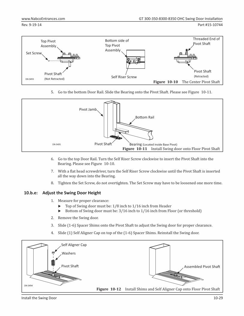
10.b.d: Temporily Install the Swing Door
1.►Go to the Pivot side of Header. Locate the Pivot Assembly.
2.►Loosen the Set Screw located directly above the Pivot Shaft. Please see Figure 10-10.
3.►Go to the Self Riser screw located underneath the Pivot Assembly.
4.►Turn the Self Riser Screw counter-clockwise to retract the Pivot Shaft.
Rev. 9-19-14 Part #15-10744www.NabcoEntrances.com� GT�300-350-8300-8350�OHC�Swing�Door�Installation
Install�the�Swing�Door� 10-29
DN 0493
Pivot Sha� (Not Retracted)
Pivot Sha� (Retracted)
Threaded End ofPivot Sha�
Set Screw
Self Riser Screw
Bo� om side of Top PivotAssembly
Top PivotAssembly
Figure 10-10 The Center Pivot Shaft
5.►Go to the bottom Door Rail. Slide the Bearing onto the Pivot Shaft. Please see Figure 10-11.
Figure 10-11 Install Swing door onto Floor Pivot ShaftDN 0495
Pivot Jamb
Bo� om Rail
Bearing (Located inside Base Pivot)Pivot Sha�
6.►Go to the top Door Rail. Turn the Self Riser Screw clockwise to insert the Pivot Shaft into the Bearing. Please see Figure 10-10.
7.►With a flat head screwdriver, turn the Self Riser Screw clockwise until the Pivot Shaft is inserted all the way down into the Bearing.
8.►Tighten the Set Screw, do not overtighten. The Set Screw may have to be loosened one more time.
10.b.e: Adjust the Swing Door Height
1.►Measure for proper clearance: X Top of Swing door must be: 1/8 inch to 1/16 inch from Header X Bottom of Swing door must be: 3/16 inch to 1/16 inch from Floor (or threshold)
2.►Remove the Swing door.
3.►Slide (1-6) Spacer Shims onto the Pivot Shaft to adjust the Swing door for proper clearance.
4.►Slide (1) Self Aligner Cap on top of the (1-6) Spacer Shims. Reinstall the Swing door.
DN 0494
Washers
Self Aligner Cap
Pivot Sha� Assembled Pivot Sha�
Figure 10-12 Install Shims and Self Aligner Cap onto Floor Pivot Shaft
GT�300-350-8300-8350�OHC�Swing�Door�Installation� www.NabcoEntrances.comPart #15-10744 Rev. 9-19-14
10-30� Install�the�Swing�Door
10.b.f: Align the Swing Door
1.►Fully open the Swing door.
2.►Go to the Track Assembly located inside the Top Rail.
3.►Loosen (1) 1/4-20x1-1/4 inch Socket Head Screw.
4.►Slide the Track Assembly back and forth until the Swing door is properly aligned.a. It is recommended to use a Level.
5.►Tighten the Socket Head Screw but do not tighten all the way down.a. The Socket Head Cap Screw may need to be loosened one more time.
10.c.g: Permanently Install the Track inside the Top Door Rail
1.►Fully open the Swing door.
2.►Use the Track as a template. Mark a vertical line across the horizontal line inside each pre-drilled screw hole. Each mark is the center of (6) .322 anchor holes.
3.►Remove the Swing door.
4.►Lay the Swing door on a flat surface that is sturdy enough to keep the door stable, and high enough to see while drilling. a. Protect Swing door from scratches.
5.►Drill (6) .322 anchor holes.
6.►Countersink the anchor hole to .53 diameter x 82 degrees.a. It is recommended to drill tap threads for anchors in a steel or aluminum structure.
7.►Insert (6) 1/4-20 tapped Rivnut into each .322 anchor hole.
8.►Secure the Track to the Web with (3) 1/4-20x2 inch Socket Head screws and (3) 1/4-20x1-1/2 inch Phillips Head screws. Tighten but do not overtighten. Please see Figure 9-13.
10.c.h: Permanently Install the Swing Door
1.►Follow instructions within subsection 10.b.d.
Rev. 9-19-14 Part #15-10744www.NabcoEntrances.com� GT�300-350-8300-8350�OHC�Swing�Door�Installation
Install�the�Swing�Arm� 11-31
CHAPTER 11: INSTALL THE SWING ARM
Section 11a: Set Pre-Load
Proper Preload is critical for the Control and Operator to open/close the Swing Door correctly.
Power must be turned OFF during the Swing Arm installation.
Ensure the Motor/Operator is plugged into the Controller.
1.►Ensure the Spring on the Operator is in the Unwound (0�) position.a. The Motor/Operator is shipped in the Unwound (0�) position.
2.►Obtain (1) Pin or 1/8 inch Allen Wrench.
3.►Go underneath the Header. Locate the Operator Spindle.
4.►Slide the Swing Arm onto the Spindle.
5.►In order to achieve correct Back Check and Latch Check positions, the Spring on the Operator must be wound up approximately 130 - 140 degrees. With a firm grip, from the Unwound (0 degree) position, rotate the Swing Arm approximately 60 degrees:
X Clockwise ► Counter-Clockwise•►For Left Handing •►For Right Handing
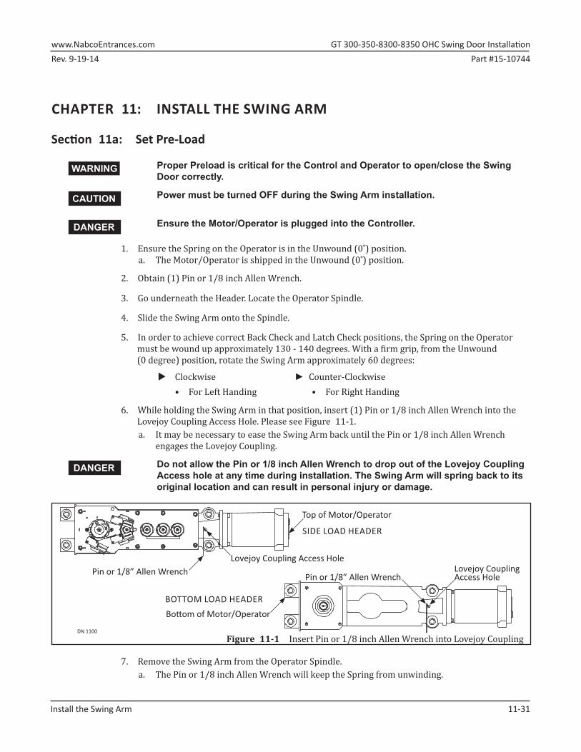
6.►While holding the Swing Arm in that position, insert (1) Pin or 1/8 inch Allen Wrench into the Lovejoy Coupling Access Hole. Please see Figure 11-1.a. It may be necessary to ease the Swing Arm back until the Pin or 1/8 inch Allen Wrench
engages the Lovejoy Coupling.
Do not allow the Pin or 1/8 inch Allen Wrench to drop out of the Lovejoy Coupling Access hole at any time during installation. The Swing Arm will spring back to its original location and can result in personal injury or damage.
DN 1100
Pin or 1/8” Allen WrenchLovejoy CouplingAccess Hole
BOTTOM LOAD HEADER
SIDE LOAD HEADER
Bo om of Motor/Operator
Top of Motor/Operator
Lovejoy Coupling Access HolePin or 1/8” Allen Wrench
Figure 11-1 Insert Pin or 1/8 inch Allen Wrench into Lovejoy Coupling
7.►Remove the Swing Arm from the Operator Spindle.a. The Pin or 1/8 inch Allen Wrench will keep the Spring from unwinding.
WARNING
CAUTION
DANGER
DANGER
GT�300-350-8300-8350�OHC�Swing�Door�Installation� www.NabcoEntrances.comPart #15-10744 Rev. 9-19-14
11-32� Install�the�Swing�Arm
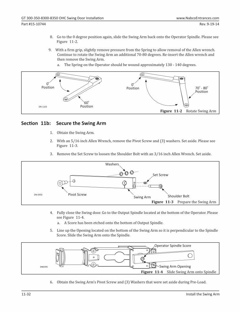
8.►Go to the 0 degree position again, slide the Swing Arm back onto the Operator Spindle. Please see Figure 11-2.
9.►With a firm grip, slightly remove pressure from the Spring to allow removal of the Allen wrench. Continue to rotate the Swing Arm an additional 70-80 degrees. Re-insert the Allen wrench and then remove the Swing Arm. a. The Spring on the Operator should be wound approximately 130 - 140 degrees.
DN 1103
0�Position
60�Position
70� - 80� Position
0�Position
Figure 11-2 Rotate Swing Arm
Section 11b: Secure the Swing Arm
1.►Obtain the Swing Arm.
2.►With an 5/16 inch Allen Wrench, remove the Pivot Screw and (3) washers. Set aside. Please see Figure 11-3.
3.►Remove the Set Screw to loosen the Shoulder Bolt with an 3/16 inch Allen Wrench. Set aside.
Figure 11-3 Prepare the Swing Arm
DN 0450 Pivot Screw
Washers
Shoulder Bolt
Set Screw
Swing Arm
4.►Fully close the Swing door. Go to the Output Spindle located at the bottom of the Operator. Please see Figure 11-4.a. A Score has been etched onto the bottom of Output Spindle.
5.►Line up the Opening located on the bottom of the Swing Arm so it is perpendicular to the Spindle Score. Slide the Swing Arm onto the Spindle.
Figure 11-4 Slide Swing Arm onto SpindleDN0395
Operator Spindle Score
Swing Arm Opening
6.►Obtain the Swing Arm’s Pivot Screw and (3) Washers that were set aside during Pre-Load.
Rev. 9-19-14 Part #15-10744www.NabcoEntrances.com� GT�300-350-8300-8350�OHC�Swing�Door�Installation
Install�the�Swing�Arm� 11-33
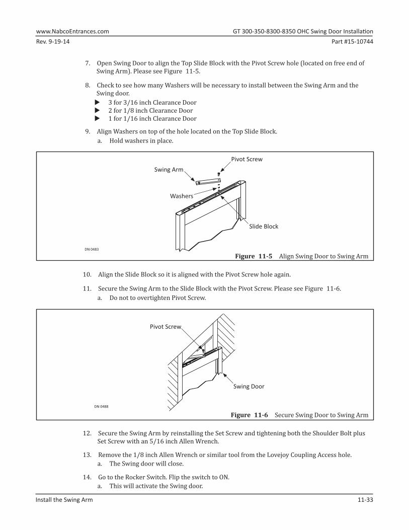
7.►Open Swing Door to align the Top Slide Block with the Pivot Screw hole (located on free end of Swing Arm). Please see Figure 11-5.
8.►Check to see how many Washers will be necessary to install between the Swing Arm and the Swing door.
X 3 for 3/16 inch Clearance Door X 2 for 1/8 inch Clearance Door X 1 for 1/16 inch Clearance Door
9.►Align Washers on top of the hole located on the Top Slide Block.a. Hold washers in place.
Figure 11-5 Align Swing Door to Swing ArmDN 0483
Swing Arm
Slide Block
Pivot Screw
Washers
10.►Align the Slide Block so it is aligned with the Pivot Screw hole again.
11.►Secure the Swing Arm to the Slide Block with the Pivot Screw. Please see Figure 11-6.a. Do not to overtighten Pivot Screw.
Figure 11-6 Secure Swing Door to Swing ArmDN 0488
Pivot Screw
Swing Door
12.►Secure the Swing Arm by reinstalling the Set Screw and tightening both the Shoulder Bolt plus Set Screw with an 5/16 inch Allen Wrench.
13.►Remove the 1/8 inch Allen Wrench or similar tool from the Lovejoy Coupling Access hole.a. The Swing door will close.
14.►Go to the Rocker Switch. Flip the switch to ON.a. This will activate the Swing door.
GT�300-350-8300-8350�OHC�Swing�Door�Installation� www.NabcoEntrances.comPart #15-10744 Rev. 9-19-14
11-34� Install�the�Swing�Arm
15.►Go the Magnum 4A Control. 1.►When the Swing door opens, watch the Green LED go from Blinking Fast on opening, then
Solid in Back Check to full open.2.► When the Swing door closes, watch the Green LED go from Blinking slowly, to Flashing
slowly when opening to Solid OFF for Latch Check (approximately 10° closed).
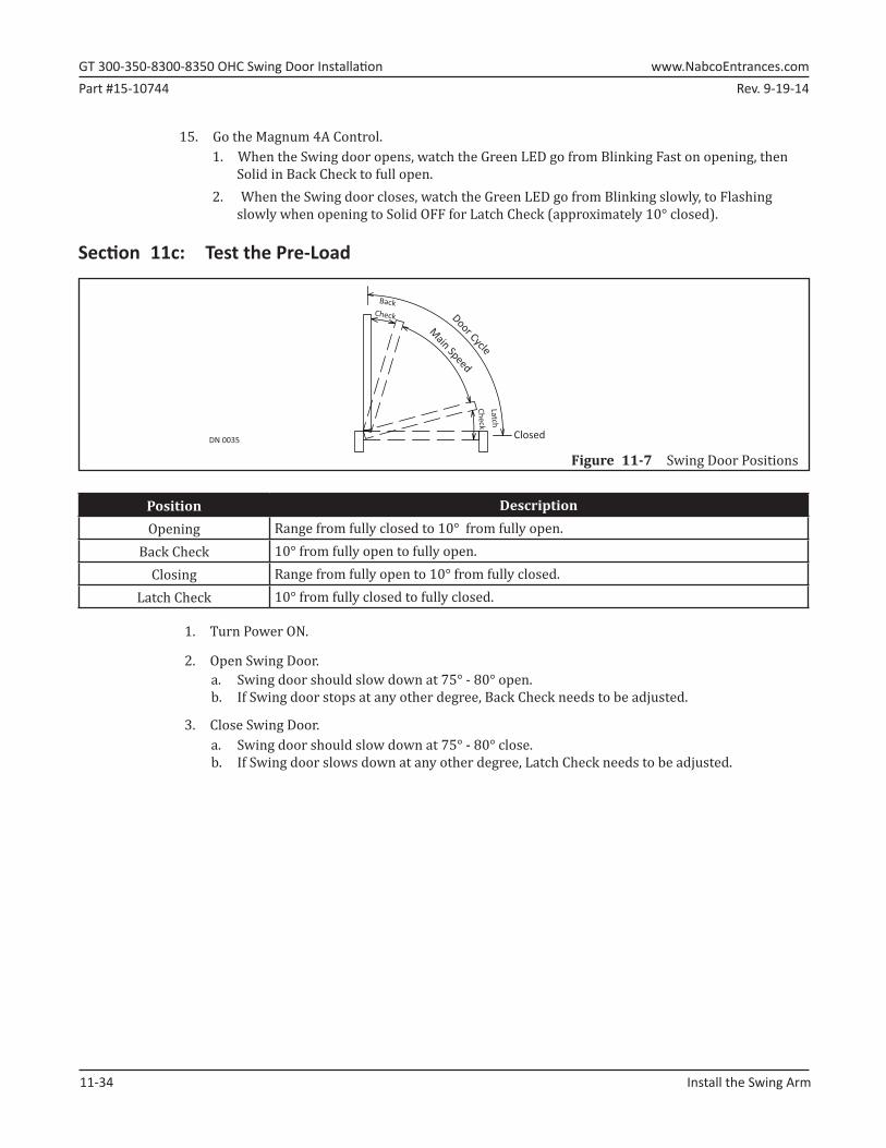
Section 11c: Test the Pre-Load
Figure 11-7 Swing Door PositionsDN 0035
BackCheck
Latch
Check
Main SpeedDoor Cycle
Closed
Position DescriptionOpening Range from fully closed to 10° from fully open.
Back Check 10° from fully open to fully open.Closing Range from fully open to 10° from fully closed.
Latch Check 10° from fully closed to fully closed.
1.►Turn Power ON.
2.►Open Swing Door.a. Swing door should slow down at 75° - 80° open.b. If Swing door stops at any other degree, Back Check needs to be adjusted.
3.►Close Swing Door.a. Swing door should slow down at 75° - 80° close.b. If Swing door slows down at any other degree, Latch Check needs to be adjusted.
Rev. 9-19-14 Part #15-10744www.NabcoEntrances.com� GT�300-350-8300-8350�OHC�Swing�Door�Installation
Pre-Load�Adjustments� 12-35
CHAPTER 12: PRE-LOAD ADJUSTMENTSNote: Adjustments to the Cam Assembly is rarely necessary. It is recommended to adjust the Cams
Assembly as a last resort.
Note: It is recommended to obtain one of the following Manuals to use as reference: X Magnum 4A Manual; 15-10682 X Analog Control Manual; 15-10745
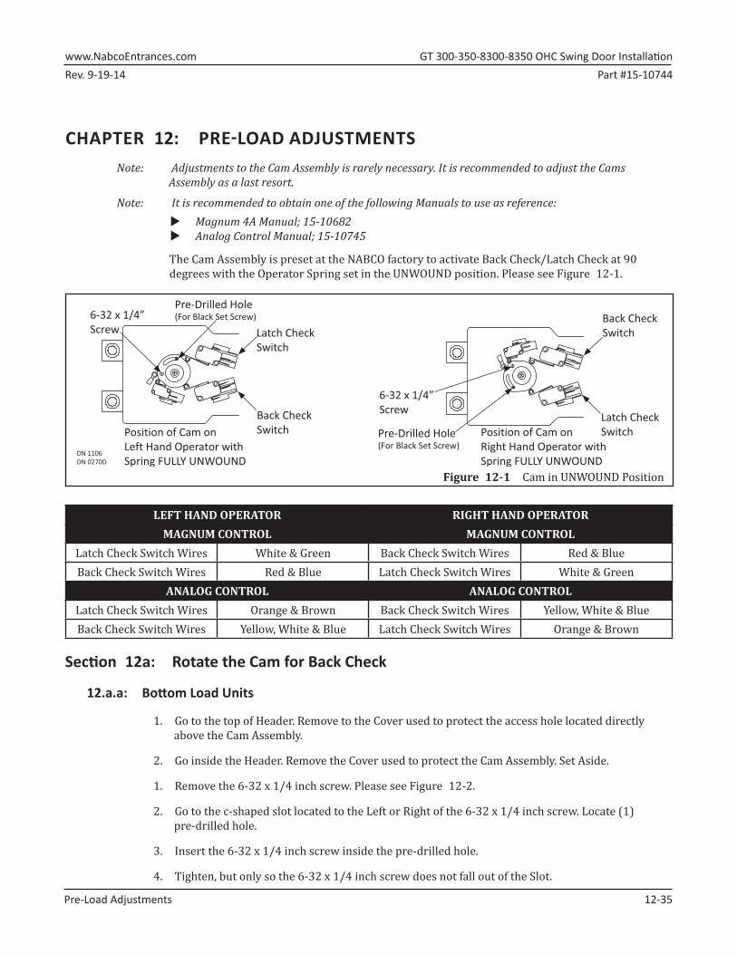
The Cam Assembly is preset at the NABCO factory to activate Back Check/Latch Check at 90 degrees with the Operator Spring set in the UNWOUND position. Please see Figure 12-1.
DN 1106DN 0270D
Position of Cam onRight Hand Operator withSpring FULLY UNWOUND
Back CheckSwitch
Latch CheckSwitchPre-Drilled Hole
(For Black Set Screw)
Latch CheckSwitch
Back CheckSwitchPosition of Cam on
Left Hand Operator withSpring FULLY UNWOUND
Pre-Drilled Hole(For Black Set Screw)6-32 x 1/4”
Screw
6-32 x 1/4” Screw
Figure 12-1 Cam in UNWOUND Position
LEFT HAND OPERATOR RIGHT HAND OPERATORMAGNUM CONTROL MAGNUM CONTROL
Latch Check Switch Wires White & Green Back Check Switch Wires Red & BlueBack Check Switch Wires Red & Blue Latch Check Switch Wires White & Green
ANALOG CONTROL ANALOG CONTROLLatch Check Switch Wires Orange & Brown Back Check Switch Wires Yellow, White & BlueBack Check Switch Wires Yellow, White & Blue Latch Check Switch Wires Orange & Brown
Section 12a: Rotate the Cam for Back Check
12.a.a: Bottom Load Units
1.►Go to the top of Header. Remove to the Cover used to protect the access hole located directly above the Cam Assembly.
2.►Go inside the Header. Remove the Cover used to protect the Cam Assembly. Set Aside.
1.►Remove the 6-32 x 1/4 inch screw. Please see Figure 12-2.
2.►Go to the c-shaped slot located to the Left or Right of the 6-32 x 1/4 inch screw. Locate (1) pre-drilled hole.
3.►Insert the 6-32 x 1/4 inch screw inside the pre-drilled hole.
4.►Tighten, but only so the 6-32 x 1/4 inch screw does not fall out of the Slot.
GT�300-350-8300-8350�OHC�Swing�Door�Installation� www.NabcoEntrances.comPart #15-10744 Rev. 9-19-14
12-36� Pre-Load�Adjustments
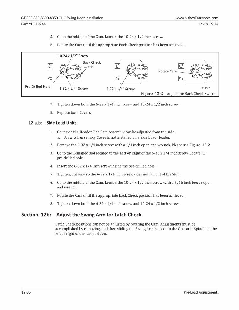
5.►Go to the middle of the Cam. Loosen the 10-24 x 1/2 inch screw.
6.►Rotate the Cam until the appropriate Back Check position has been achieved.
DN 1107
10-24 x 1/2” Screw
Pre-Drilled Hole 6-32 x 1/4” Screw
Back Check Switch
6-32 x 1/4” Screw
Rotate Cam
Figure 12-2 Adjust the Back Check Switch
7.►Tighten down both the 6-32 x 1/4 inch screw and 10-24 x 1/2 inch screw.
8.►Replace both Covers.
12.a.b: Side Load Units
1.►Go inside the Header. The Cam Assembly can be adjusted from the side.a. A Switch Assembly Cover is not installed on a Side Load Header.
2.►Remove the 6-32 x 1/4 inch screw with a 1/4 inch open end wrench. Please see Figure 12-2.
3.►Go to the C-shaped slot located to the Left or Right of the 6-32 x 1/4 inch screw. Locate (1) pre-drilled hole.
4.►Insert the 6-32 x 1/4 inch screw inside the pre-drilled hole.
5.►Tighten, but only so the 6-32 x 1/4 inch screw does not fall out of the Slot.
6.►Go to the middle of the Cam. Loosen the 10-24 x 1/2 inch screw with a 5/16 inch box or open end wrench.
7.►Rotate the Cam until the appropriate Back Check position has been achieved.
8.►Tighten down both the 6-32 x 1/4 inch screw and 10-24 x 1/2 inch screw.
Section 12b: Adjust the Swing Arm for Latch Check
Latch Check positions can not be adjusted by rotating the Cam. Adjustments must be accomplished by removing, and then sliding the Swing Arm back onto the Operator Spindle to the left or right of the last position.