Embed Size (px)
Citation preview
This presentation does not contain any proprietary, confidential, or otherwise restricted information
Overcharge Protection for PHEV Batteries
Guoying Chen and Thomas J. Richardson Lawrence Berkeley National Laboratory
May 17, 2012
Project ID: ES037
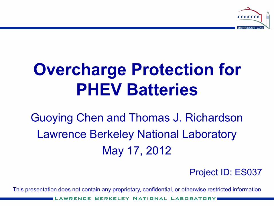
Overview
Timeline
• Start date: March 2009
• End date: ongoing
• Percent complete: ongoing
Budget
• Total project funding - FY09 $190K - FY10 $190K - FY11 $240K
Partners
• ANL, BNL, INL, and SNL
• Berkeley program lead: Venkat Srinivasan
Barriers Addressed
• Cycle life
• Abuse tolerance for PHEV Li-ion batteries

Objectives\Milestones
• Develop a reliable, inexpensive overcharge-protection mechanism. • Use electroactive polymers for internal, self-actuating protection. • Minimize cost, maximize rate capability and cycle life of
overcharge protection in high-energy Li-ion batteries for PHEV applications.
Objectives
Milestones
• Investigate overcharge protection performance of polymer-fiber incorporated composite separators (Jun. 2012).
• Evaluate the property and performance of new high-voltage electroactive polymer candidates (Jul. 2012).
• Report overcharge protection for pouch cells and other large-scale battery cells (Sep. 2012).
• Attend review meetings and present research results.

The Need for Overcharge Protection
http://www.rokemneedlearts.com
Causes of overcharge • Cell imbalance in the battery pack • Charging exceeding electrode capacity • Over-voltage excursions • Low-temperature operation under high
internal resistance
Consequences of overcharge • Cathode degradation, metal ion
dissolution, O2 evolution • Electrolyte breakdown, CO2 evolution • Li deposition on anode, H2 evolution • Overheating, breakdown of anode SEI
layer and thermal runaway • Current collector corrosion • Explosion, fire, toxics released • Accelerated capacity/power fade,
shortened battery life
http://stores.headway-headquarters.com Series-connected LiFePO4 battery pack

0 0.02
0.04
0.07
0.11 0.14 0.19 0.22 0.25
0.09
0.06
0.03
SOC Conductivity (S/cm)
1 x 10⁻¹
1 x 10⁻²
3 x 10⁻³
1 x 10⁻⁴
1 x 10⁻⁵
1 x 10⁻⁶
3 x 10⁻⁷
1 x 10⁻⁸
7 x 10⁻⁹
3 x 10⁻⁹
2 x 10⁻⁹
1 x 10⁻⁹ (neutral)
(oxidized)
Anio
n do
ping
leve
l
• Highly reversible redox reactions – capable of reversible, long-term protection. • Rapid changes in electronic conductivity upon the redox reaction – cell voltage
regulates the resistivity of the polymer shunt.
Our Approach – Electroactive Polymers
-0.4
-0.2
0.0
0.2
0.4
1.0 1.5 2.0 2.5 3.0 3.5 4.0 4.5Potential vs. Li+/Li (V)
Cur
rent
Den
sity
(mA
/cm
2 )
Potential vs. Li+/Li (V)
S SS
R R
R
x
+ PF6-
(Polaron)
S SS
R R
R
x
++ 2PF6-
(Bipolaron)
S
R
n
20 cycles
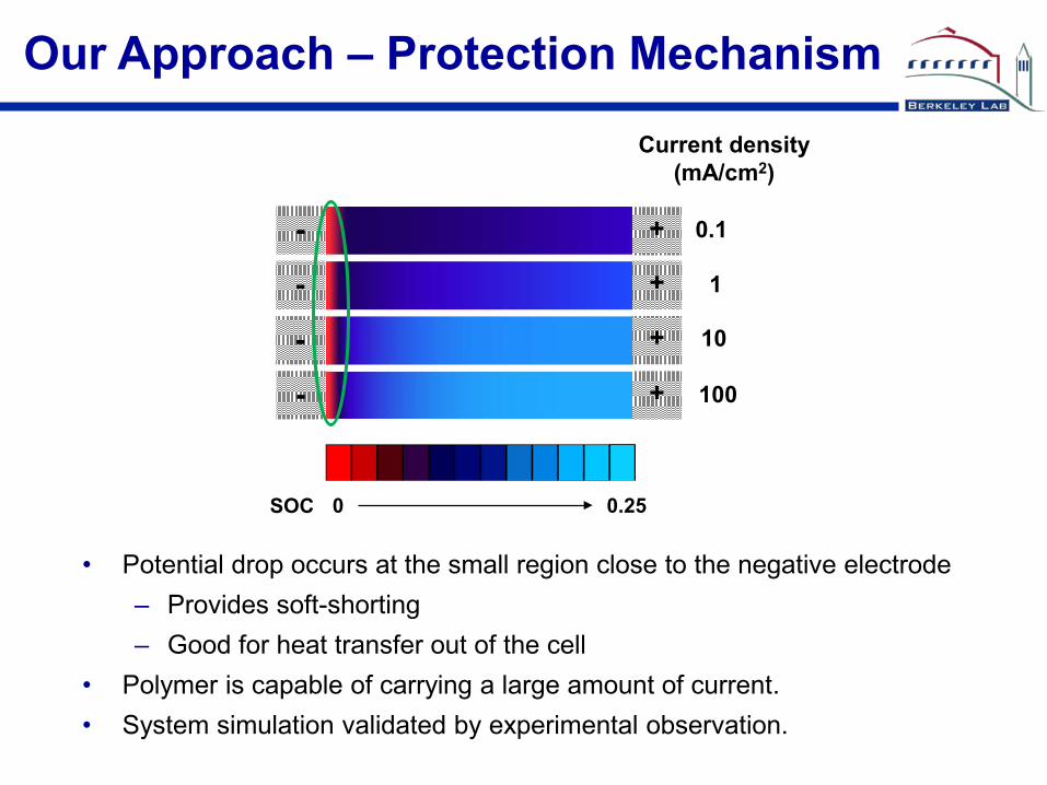
• Potential drop occurs at the small region close to the negative electrode – Provides soft-shorting – Good for heat transfer out of the cell
• Polymer is capable of carrying a large amount of current. • System simulation validated by experimental observation.
Our Approach – Protection Mechanism
0.1
1
10
100
Current density (mA/cm2)
SOC 0 0.25
+
+
+
+
-
-
-
-

Our Approach – Advantages
Do
Dr
+ _ -e-
A° A°
A+ A+
+e-
Redox shuttle method • Diffusion limited - low rate capability and poor low temperature performance • Interference with the cell chemistry • Solubility and volatility issues
External electronics
• Expensive • Added weight and volume • One bad cell kills the whole string
Anode
Cathode
Current Collector
Current Collector
Electroactive Polymer Composite
Sandwich
+ -
Ano
de
Cat
hode
Cur
rent
Col
lect
or
S
epar
ator
Cur
rent
Col
lect
or
Cur
rent
Col
lect
or
Electroactive Polymer Composite A
node
Cur
rent
Col
lect
or
Cur
rent
Col
lect
or
External
Versatility of the polymer approach – cell configuration
Anode
Cathode
Current Collector
Separator
Current Collector Current Collector
Ele
ctro
activ
e Po
lym
er
Com
posi
te
Parallel
Tabs
Technical Accomplishments
• PFOP was found to have an extended stability window in lithium battery electrolytes. Its ability to provide single-polymer overcharge protection was demonstrated. • Modification on electroactive polymer composites led to 20x increase in sustainable current density and excellent long-term overcharge protections for several cell chemistries, including Gen2 and Gen3. • Electroactive polymer-fibers and their composite mats were prepared by an electrospinning technique. The behavior of the fibers as charge carriers in Li-ion batteries was characterized in an in situ optical cell.
-0.4
-0.2
0.0
0.2
0.4
1.0 1.5 2.0 2.5 3.0 3.5 4.0 4.5Cur
rent
Den
sity
(mA/
cm2 )
Potential vs. Li+/Li (V)
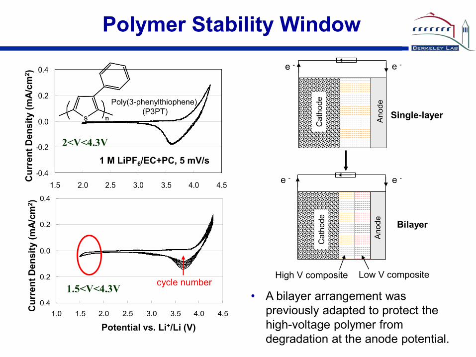
1.5<V<4.3V
-0.4
-0.2
0.0
0.2
0.4
1.5 2.0 2.5 3.0 3.5 4.0 4.5
Cur
rent
Den
sity
(mA/
cm2 )
2<V<4.3V
1 M LiPF6/EC+PC, 5 mV/s
Poly(3-phenylthiophene) (P3PT)
S nS n
Polymer Stability Window
Ano
de
Cat
hode
e - e -
High V composite Low V composite
Ano
de
Cat
hode
e - e -
• A bilayer arrangement was previously adapted to protect the high-voltage polymer from degradation at the anode potential.
Single-layer
Bilayer
cycle number

• PFOP has the highest onset oxidation voltage (4.25V) among the investigated electroactive polymers. • Improved low-voltage stability at anode.
Extended Redox Window in PFOP
0.0 1.0 2.0 3.0 4.0 5.0-0.06
-0.04
-0.02
0.00
0.02
0.04
0.06
Cu
rren
t (m
A)
Voltage (V)
5 mV/s, 10 cycles
Cycle number
Poly[(9,9-dioctylfluorenyl-2,7-diyl)-co-(1,4-phenylene)] (PFOP)

0 10 20 30 40 5080
120
160
200
240
Spec
ific
capa
city
(mAh
/g)
Cycling number
charge discharge
Li
LiFePO4
Current Collector
Current Collector
PFOP/Celgard
Single-polymer Protection Achieved
• Cell cycled at 0.5C and 40% overcharge. • Improved low-voltage stability allows for stable single-polymer protection. • Improved discharge capacity upon cycling may be a result of enhanced conduction in the electrode.
0.0 0.5 1.0 1.5 2.0 2.5 3.0 3.5 4.0 4.5
2.5
3.0
3.5
4.0
4.5
5.0
Volta
ge/V
Time/h
10 20 30 36 38 40 41 43 50
PDFP-LFP-OC1h 0.5C
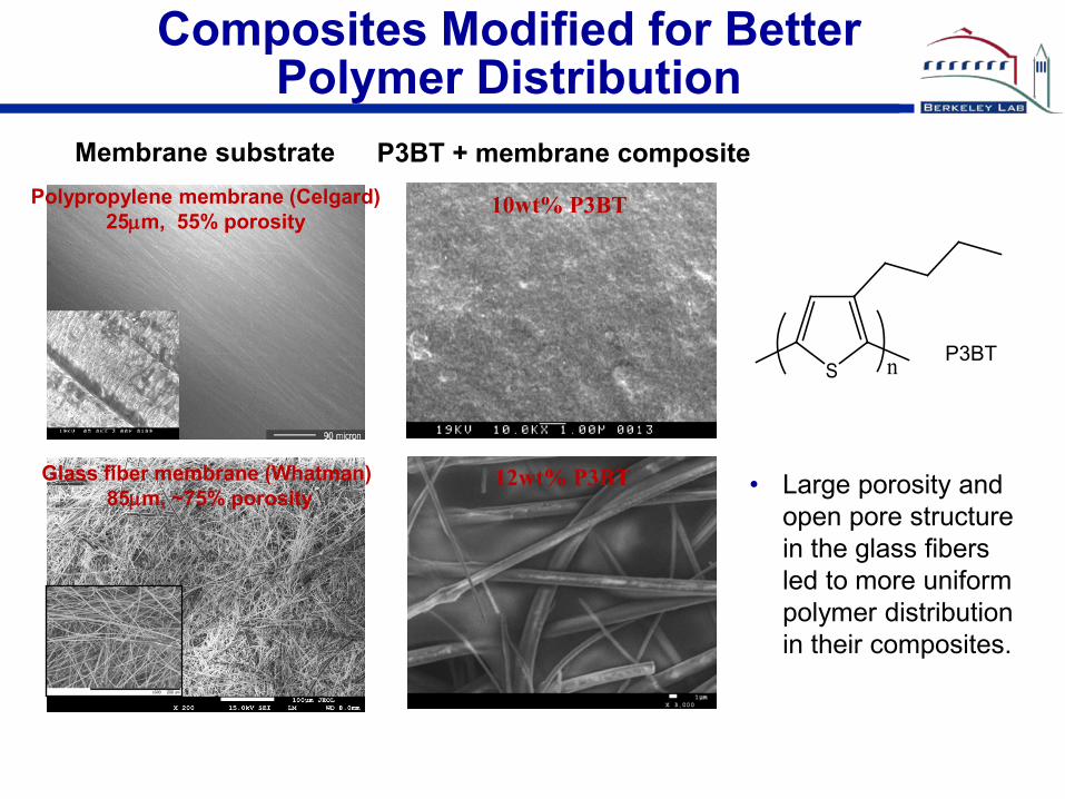
Composites Modified for Better Polymer Distribution
Polypropylene membrane (Celgard) 25µm, 55% porosity
Glass fiber membrane (Whatman) 85µm, ~75% porosity
Membrane substrate
10wt% P3BT
12wt% P3BT
P3BT + membrane composite
P3BT S n
• Large porosity and open pore structure in the glass fibers led to more uniform polymer distribution in their composites.
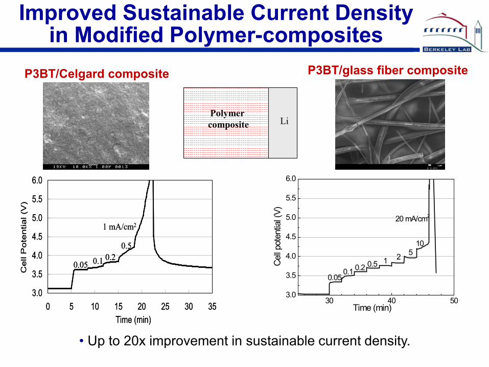
Improved Sustainable Current Density in Modified Polymer-composites
Li Polymer composite
• Up to 20x improvement in sustainable current density.
3.0
3.5
4.0
4.5
5.0
5.5
6.0
0 5 10 15 20 25 30 35Time (min)
Cell
Pote
ntia
l (V
)
0.05 0.1 0.20.5
1 mA/cm2
3.0
3.5
4.0
4.5
5.0
5.5
6.0
0 5 10 15 20 25 30 35Time (min)
Cell
Pote
ntia
l (V
)
0.05 0.1 0.20.5
1 mA/cm2
30 40 503.0
3.5
4.0
4.5
5.0
5.5
6.0
2
0.05Ce
ll pot
entia
l (V)
Time (min)
0.1 0.2 0.5 15
10
20 mA/cm2
P3BT/Celgard composite P3BT/glass fiber composite
580 585 590 595 600 605 610 6152.5
3.0
3.5
4.0
4.5
5.0
Volta
ge (V
)
Time (h)
158th
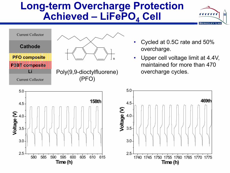
• Cycled at 0.5C rate and 50% overcharge.
• Upper cell voltage limit at 4.4V, maintained for more than 470 overcharge cycles.
1740 1745 1750 1755 1760 1765 1770 17752.5
3.0
3.5
4.0
4.5
5.0
Volta
ge (V
)
Time (h)
469th
Long-term Overcharge Protection Achieved – LiFePO4 Cell
Li Current Collector
Current Collector
P3BT composite
PFO composite
Cathode
Poly(9,9-dioctylfluorene) (PFO)
n
0 100 200 300 400 5000
50
100
150
200
250
Charge DischargeSp
ecifi
c ca
paci
ty (m
Ah/g
)
Cycle number
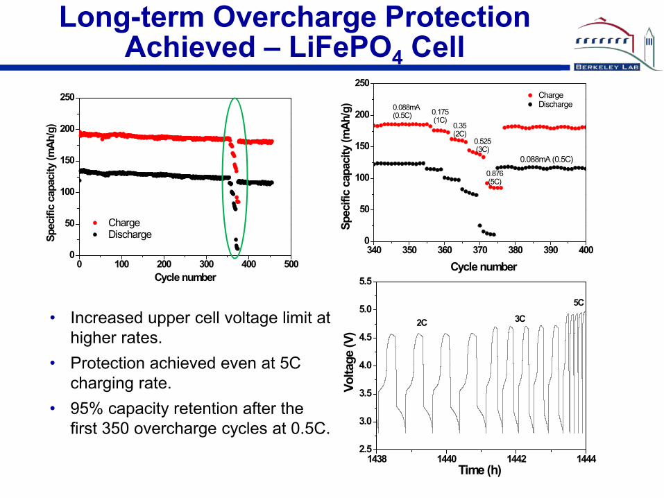
• Increased upper cell voltage limit at higher rates.
• Protection achieved even at 5C charging rate.
• 95% capacity retention after the first 350 overcharge cycles at 0.5C.
340 350 360 370 380 390 4000
50
100
150
200
250
Spec
ific
capa
city
(mAh
/g)
Cycle number
0.088mA (0.5C)
0.088mA (0.5C)
ChargeDischarge
0.35(2C)
0.175 (1C)
0.525 (3C)
0.876 (5C)
1438 1440 1442 14442.5
3.0
3.5
4.0
4.5
5.0
5.5
Time (h)
Volta
ge (V
)
5C
3C2C
Long-term Overcharge Protection Achieved – LiFePO4 Cell
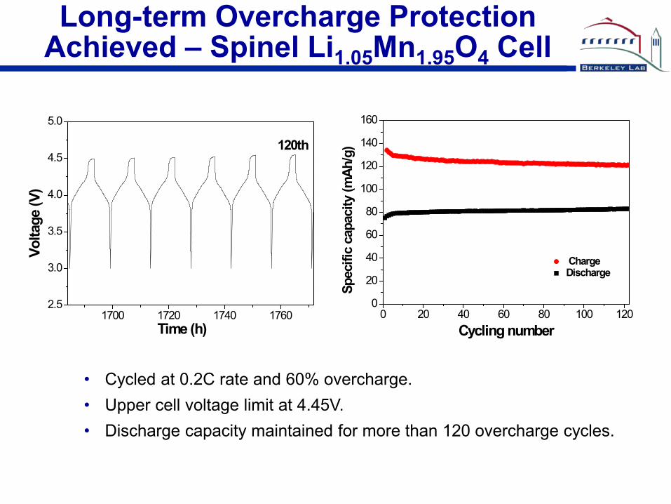
Long-term Overcharge Protection Achieved – Spinel Li1.05Mn1.95O4 Cell
• Cycled at 0.2C rate and 60% overcharge. • Upper cell voltage limit at 4.45V. • Discharge capacity maintained for more than 120 overcharge cycles.
1700 1720 1740 17602.5
3.0
3.5
4.0
4.5
5.0
Time (h)
Volta
ge (V
)
120th
0 20 40 60 80 100 1200
20
40
60
80
100
120
140
160
ChargeDischarge
Spec
ific
capa
city
(mAh
/g)
Cycling number
1190 1200 1210 12202.83.03.23.43.63.84.04.24.44.64.8
Volta
ge (V
)
Time (h)
200th
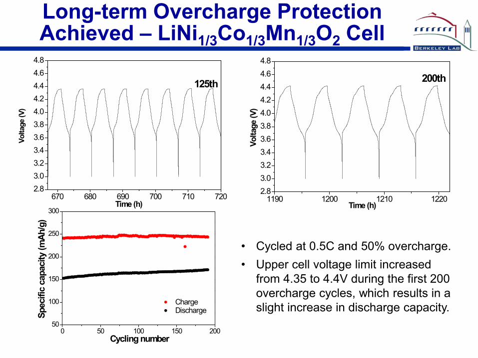
Long-term Overcharge Protection Achieved – LiNi1/3Co1/3Mn1/3O2 Cell
• Cycled at 0.5C and 50% overcharge. • Upper cell voltage limit increased
from 4.35 to 4.4V during the first 200 overcharge cycles, which results in a slight increase in discharge capacity.
0 50 100 150 20050
100
150
200
250
300
Charge DischargeSp
ecifi
c ca
paci
ty (m
Ah/g
)
Cycling number
670 680 690 700 710 720
2.83.03.23.43.63.84.04.24.44.64.8
Volta
ge (V
)
Time (h)
125th
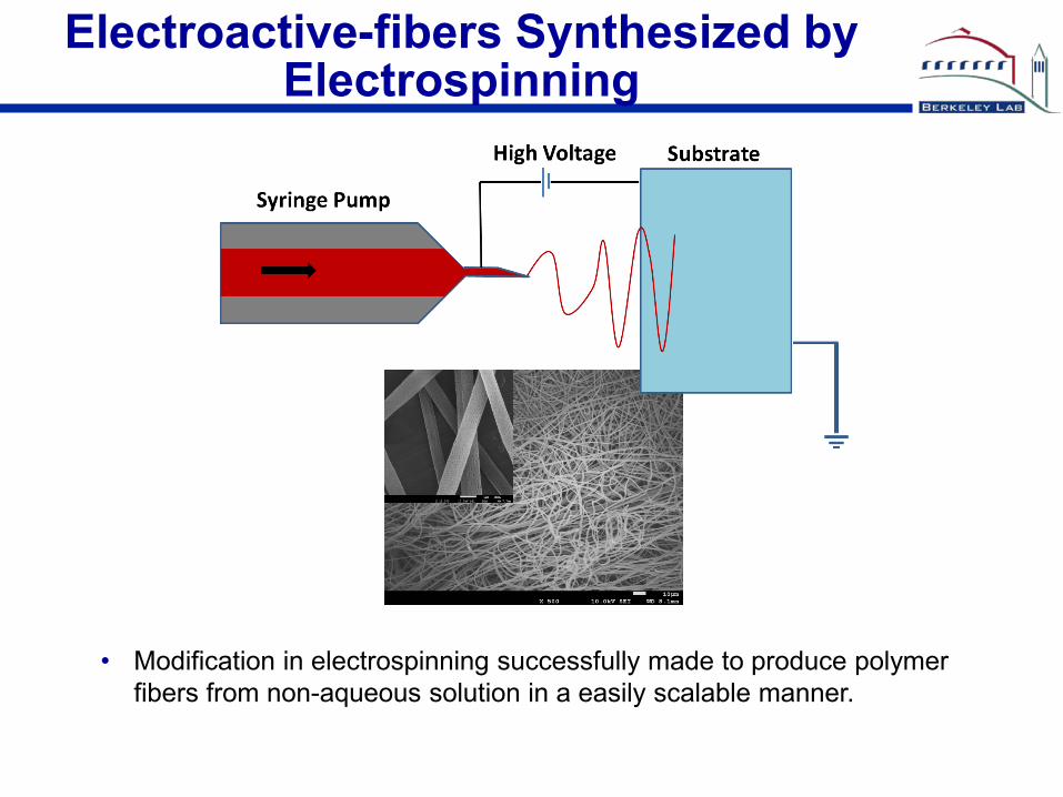
Electroactive-fibers Synthesized by Electrospinning
• Modification in electrospinning successfully made to produce polymer fibers from non-aqueous solution in a easily scalable manner.
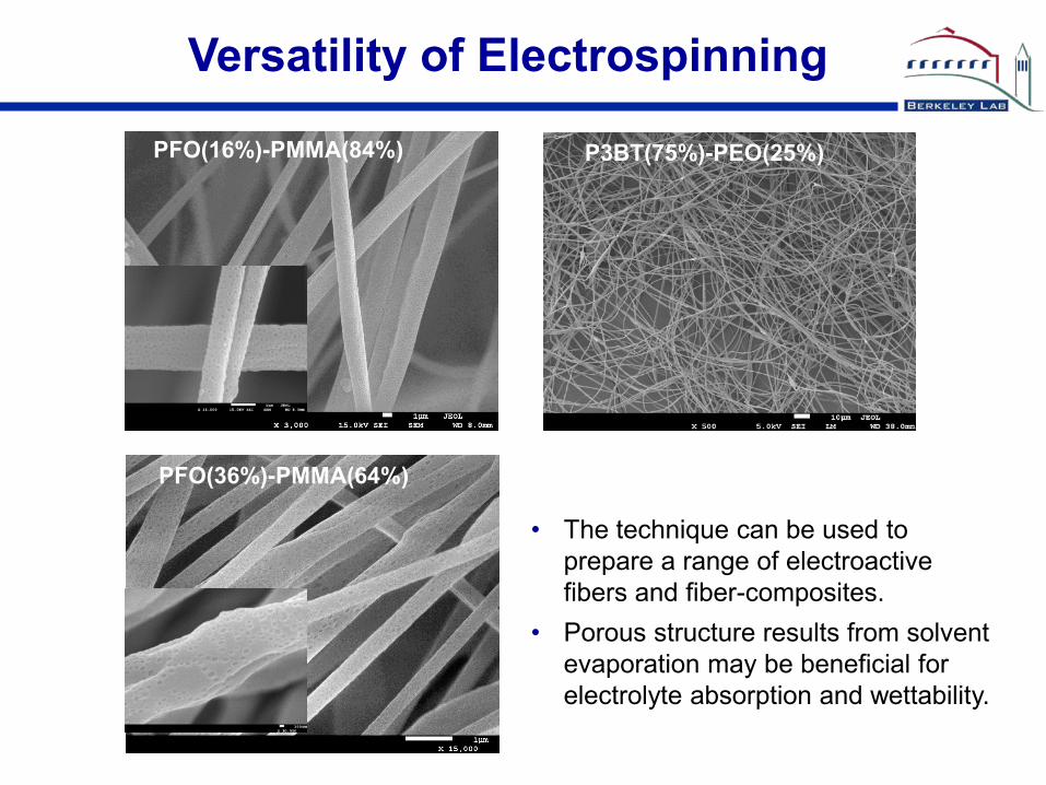
PFO(16%)-PMMA(84%)
Versatility of Electrospinning
PFO(36%)-PMMA(64%)
P3BT(75%)-PEO(25%)
• The technique can be used to prepare a range of electroactive fibers and fiber-composites.
• Porous structure results from solvent evaporation may be beneficial for electrolyte absorption and wettability.
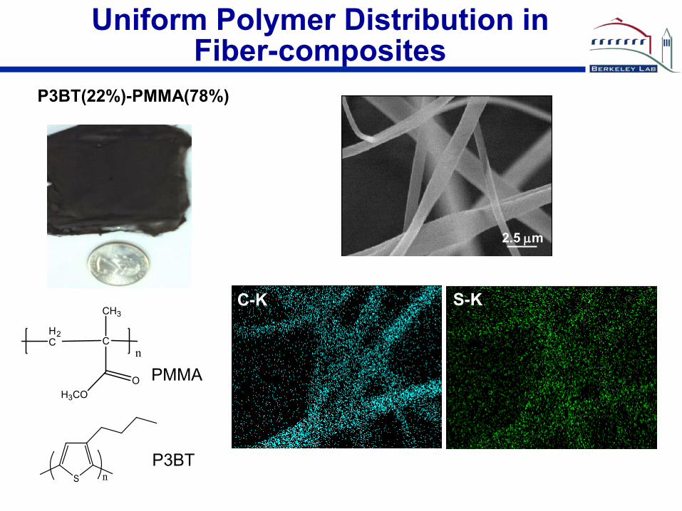
Uniform Polymer Distribution in Fiber-composites
P3BT(22%)-PMMA(78%)
2.5 µm
C-K S-K
P3BT S n
CH2C
CH3
OH3CO
n
PMMA
(-CH2CH2O-)n PEO
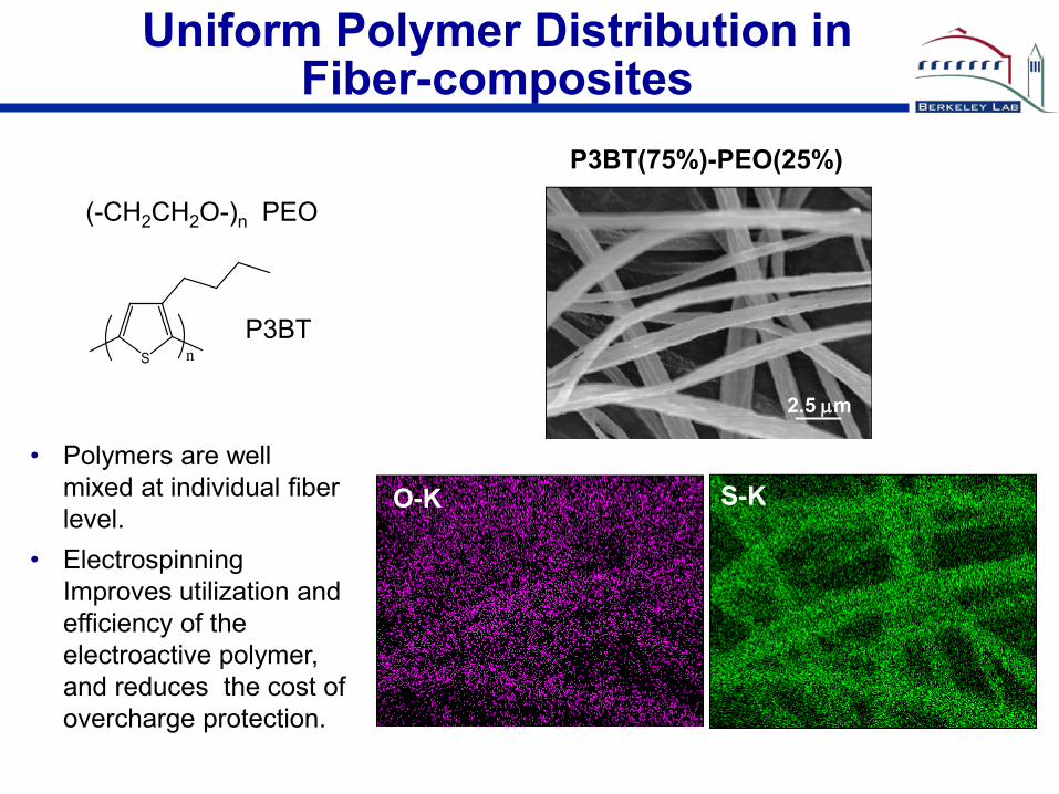
P3BT(75%)-PEO(25%)
Uniform Polymer Distribution in Fiber-composites
P3BT S n
2.5 µm
S-K O-K • Polymers are well
mixed at individual fiber level.
• Electrospinning Improves utilization and efficiency of the electroactive polymer, and reduces the cost of overcharge protection.
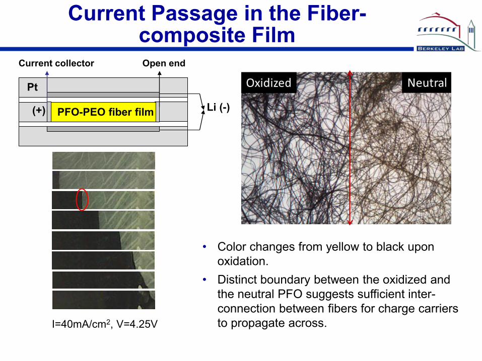
I=40mA/cm2, V=4.25V
Pt
PFO-PEO fiber film Li (-) (+)
Current collector Open end
Current Passage in the Fiber-composite Film
• Color changes from yellow to black upon oxidation.
• Distinct boundary between the oxidized and the neutral PFO suggests sufficient inter-connection between fibers for charge carriers to propagate across.

Electroactive-fiber-composite Membranes Made by Electrospinning
PFO (25%) - PEO(75%)
• Dense electroactive-fiber membranes can be made in various thickness. • A cost-effective way to produce lithium-ion battery separators capable of
voltage-regulated shunting.
Collaborations
• Robert Kostecki (LBNL) – Raman and FTIR Spectroscopy
• Yuegang Zhang (Molecular Foundry) – Electrospinning techniques
• John Kerr (LBNL) – TGA and DSC, AFM
• Vince Battaglia, Marca Doeff, Gao Liu (LBNL) – Electrode fabrication
• Quy Ta, Brian Nguyen (American Dye Source, Inc.) – Electroactive polymer synthesis

Future Work
• Evaluate rate capability and cycle life of the cells protected by electrospun electroactive-fiber-separators.
• Explore alternative polymer placement in the cells that may lead to improved protection and lowered cost.
• Continue to explore other high-voltage electroactive polymers that are suitable for overcharge protection for PHEV batteries. Optimize the morphology of their composites for maximum protection.
• Investigate overcharge protection for the cells with other high-voltage cathodes, particularly the Li and Mn rich Li1+xM1-xO2-type cathodes.
• Collaborate with industry and other labs to “scaling-up” the approach.

Summary
• An electroactive polymer with extended stability window was discovered, which was found to be capable of single-polymer overcharge protection for lithium-ion battery cells.
• The distribution of polymer in the composite is critical for long-term overcharge protection. Protection for hundreds of cycles can be achieved by using the glass fiber composites with better distribution.
• Electroactive-fiber-composite membranes with uniform polymer distribution were made by electrospinning. This type of membranes are expected to provide improved protection with higher polymer utilization and efficiency, and they can be flexible in their placement in the cells.
• Electrospinning can be a cost-effective way to achieve overcharge protection using the electroactive polymer approach.