Embed Size (px)
Citation preview
NUMERICAL OVER CURRENT PROTECTION RELAY ADR241B_V2 T ITLE
ASHIDA Electronics Pvt. Ltd.
Page 1/1
ADITYA SERIES
Over Current Relay
Version 1.0 (For Software V1.xx and V2.xx)
Technical Manual

NUMERICAL OVER CURRENT PROTECTION RELAY ADR241B_V2 CONTENTS
ASHIDA Electronics Pvt. Ltd.
Page 1/10 CONTENTS
Safety Instruction
Introduction
Handling & Case Dimension
User’s Guide
Menu Content Table
Technical Specification
Application Guide
Communication
Installation, Relay Testing & Commissioning
Periodic Testing
Details of Internal Circuit Diagram
Problems Occurred & Hardware Software Revision

NUMERICAL OVER CURRENT PROTECTION RELAY ADR241B_V2 CONTENTS
ASHIDA Electronics Pvt. Ltd.
Page 2/10
1.0 SAFETY INSTRUCTION CONTENTS 1.1 Introduction 3
1.2 Healthy & Safety 3
1.3 Symbol & External Labels 4
1.4 Decommissioning & Disposal 4
1.5 Technical Specifications For Safety 5
1.5.1 Protective Fuse Rating 5
1.5.2 Protective Class 5
1.5.3 Installation Category 5
1.5.4 Environment 5
1.6 CE Marking 5
1.7 Revision Note 6
2.0 INTRODUCTION CONTENTS 2.1 General 3
2.2 Features 4
2.3 How to use the Manual 5
2.4 Ordering Information 7
2.5 Revision Note 9
3.0 HANDLING & CASE DIMENSION CONTENTS 3 Handling 3
3.1 Receipt of Relay 3
3.2 Unpacking 3
3.3 Handling of Electric Components 3
3.4 Storage 4
3.5 Dimensions 4
3.5.1 Connections of Power Terminals and Signal Terminals 4
3.5.2 Earthing 4
3.6 Cabinet drawing 5
3.7 Revision Note 6
NUMERICAL OVER CURRENT PROTECTION RELAY ADR241B_V2 CONTENTS
ASHIDA Electronics Pvt. Ltd.
Page 3/10
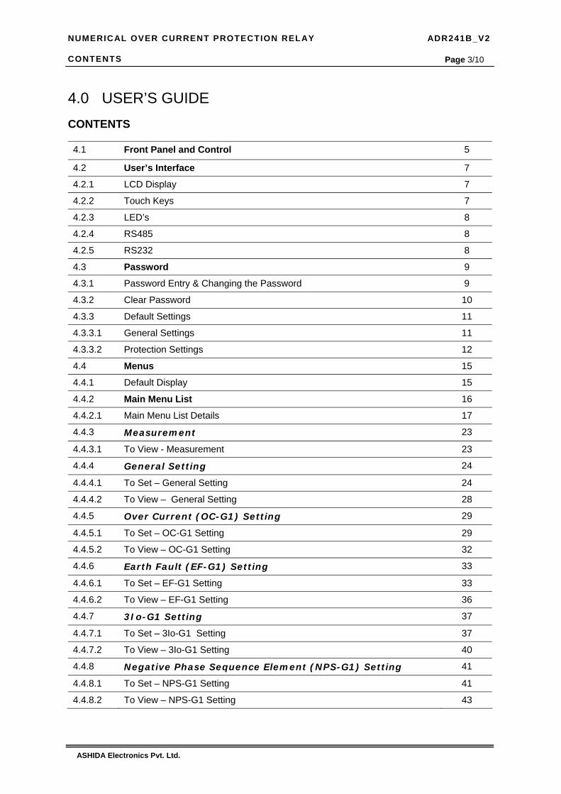
4.0 USER’S GUIDE CONTENTS
4.1 Front Panel and Control 5
4.2 User’s Interface 7
4.2.1 LCD Display 7
4.2.2 Touch Keys 7
4.2.3 LED’s 8
4.2.4 RS485 8
4.2.5 RS232 8
4.3 Password 9
4.3.1 Password Entry & Changing the Password 9
4.3.2 Clear Password 10
4.3.3 Default Settings 11
4.3.3.1 General Settings 11
4.3.3.2 Protection Settings 12
4.4 Menus 15
4.4.1 Default Display 15
4.4.2 Main Menu List 16
4.4.2.1 Main Menu List Details 17
4.4.3 Measurement 23
4.4.3.1 To View - Measurement 23
4.4.4 General Setting 24
4.4.4.1 To Set – General Setting 24
4.4.4.2 To View – General Setting 28
4.4.5 Over Current (OC-G1) Setting 29
4.4.5.1 To Set – OC-G1 Setting 29
4.4.5.2 To View – OC-G1 Setting 32
4.4.6 Earth Fault (EF-G1) Setting 33
4.4.6.1 To Set – EF-G1 Setting 33
4.4.6.2 To View – EF-G1 Setting 36
4.4.7 3Io-G1 Setting 37
4.4.7.1 To Set – 3Io-G1 Setting 37
4.4.7.2 To View – 3Io-G1 Setting 40
4.4.8 Negative Phase Sequence Element (NPS-G1) Setting 41
4.4.8.1 To Set – NPS-G1 Setting 41
4.4.8.2 To View – NPS-G1 Setting 43

NUMERICAL OVER CURRENT PROTECTION RELAY ADR241B_V2 CONTENTS
ASHIDA Electronics Pvt. Ltd.
Page 4/10 4.4.9 Over Current (OC-G2) Setting 44
4.4.9.1 To Set – OC-G2 Setting 44
4.4.9.2 To View – OC-G2 Setting 47
4.4.10 Earth Fault (EF-G2) Setting 48
4.4.10.1 To Set – EF-G2 Setting 48
4.4.10.2 To View – EF-G2 Setting 51
4.4.11 3Io-G2 Setting 52
4.4.11.1 To Set – 3Io-G2 Setting 52
4.4.11.2 To View – 3Io-G2 Setting 55
4.4.12 Negative Phase Sequence Element (NPS-G2) Setting 56
4.4.12.1 To Set – NPS-G2 Setting 56
4.4.12.2 To View – NPS-G2 Setting 58
4.4.13 Auto Recloser (ARR) Setting 59
4.4.13.1 To Set – ARR Setting 59
4.4.13.2 To View – ARR Setting 61
4.4.14 Relay/LED Configuration 62
4.4.14.1 Bit Definition for Relay/LED Configuration 62
4.4.14.2 List of Protection Function and Digital Inputs 63
4.4.14.3 To Set – Relay/LED Configuration 67
4.4.14.4 To View – Relay/LED Configuration 72
4.4.14.5 Example of Relay / LED Configuration 73
4.4.15 Fault 1 88
4.4.15.1 To View – Fault 1 Data [Fault 2 to Fault 20] 88
4.4.16 Status 89
4.4.16.1 To View – Status 89
4.4.17 Error Log 89
4.4.17.1 To View – Error Log 89
4.4.18 Close 90
4.4.19 Trip 90
4.4.20 Active Group 91
4.4.20 Date Time Setting 92
4.4.20.1 To Set – Date Time setting 92
4.4.20.2 To View – Date Time Setting 93
4.5 Input Signals 94
4.5.1 Auxiliary Supply Input 94
4.5.2 CT Secondary Input 94
4.5.3 Status Input 94
NUMERICAL OVER CURRENT PROTECTION RELAY ADR241B_V2 CONTENTS
ASHIDA Electronics Pvt. Ltd.
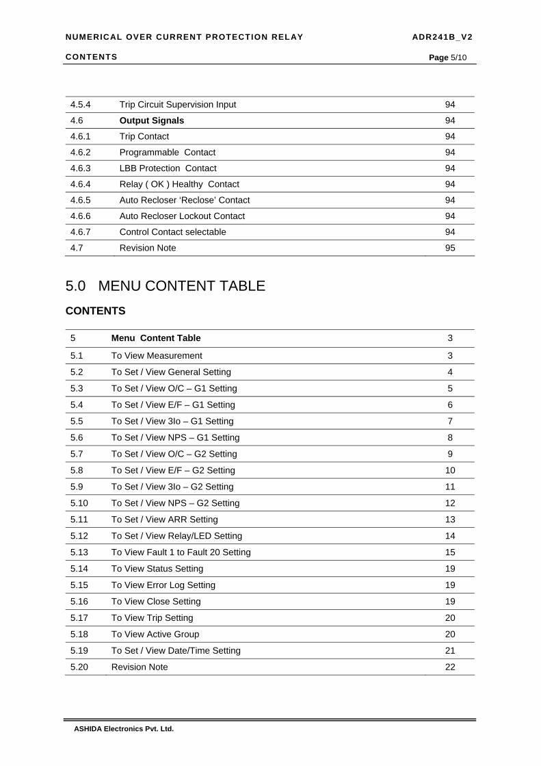
Page 5/10 4.5.4 Trip Circuit Supervision Input 94
4.6 Output Signals 94
4.6.1 Trip Contact 94
4.6.2 Programmable Contact 94
4.6.3 LBB Protection Contact 94
4.6.4 Relay ( OK ) Healthy Contact 94
4.6.5 Auto Recloser ‘Reclose’ Contact 94
4.6.6 Auto Recloser Lockout Contact 94
4.6.7 Control Contact selectable 94
4.7 Revision Note 95
5.0 MENU CONTENT TABLE CONTENTS 5 Menu Content Table 3
5.1 To View Measurement 3
5.2 To Set / View General Setting 4
5.3 To Set / View O/C – G1 Setting 5
5.4 To Set / View E/F – G1 Setting 6
5.5 To Set / View 3Io – G1 Setting 7
5.6 To Set / View NPS – G1 Setting 8
5.7 To Set / View O/C – G2 Setting 9
5.8 To Set / View E/F – G2 Setting 10
5.9 To Set / View 3Io – G2 Setting 11
5.10 To Set / View NPS – G2 Setting 12
5.11 To Set / View ARR Setting 13
5.12 To Set / View Relay/LED Setting 14
5.13 To View Fault 1 to Fault 20 Setting 15
5.14 To View Status Setting 19
5.15 To View Error Log Setting 19
5.16 To View Close Setting 19
5.17 To View Trip Setting 20
5.18 To View Active Group 20
5.19 To Set / View Date/Time Setting 21
5.20 Revision Note 22

NUMERICAL OVER CURRENT PROTECTION RELAY ADR241B_V2 CONTENTS
ASHIDA Electronics Pvt. Ltd.
Page 6/10 6.0 TECHNICAL SPECIFICATION CONTENTS
6.1 Protection Features 3
6.2 Relay Design Features 3
6.3 Block Diagram 4
6.4 Description 5
6.5 Technical Specification 6
6.6 Revision Note 10
7.0 APPLICATION GUIDE CONTENTS
7.1 Main function 3
7.2 Over Current Element 3
7.3 Earth Fault Element 3
7.4 Inverse Time Curve 4
7.4.1 C1 - Normal Inverse 1 (10 Times 3.0 sec) 5
7.4.2 C2 - Normal Inverse 2 (10 Times 1.3 sec) 6
7.4.3 C3 - Very Inverse (10 Times 1.5 sec) 7
7.4.4 C4 - Extremely Inverse (10 Times 0.8 sec) 8
7.4.5 C5 - Long Time Inverse (10 Times 13.3 sec) 9
7.5 Trip Circuit Supervision 10
7.6 Auto Recloser Logic 10
7.7 Breaker Failure Logic 10
7.8 Negative Sequence Over Current 11
7.9 Programmable Di/DO and LED 11
7.10 Monitoring Function (Event, Disturbance Recorder) 11
7.11.1 Wiring Diagram – External EF for EF protection 12
7.11.2 Wiring Diagram – Internal EF for EF Protection 13
7.12 Trip Diagram 14
7.13 Logic Diagram of RL1 to RL5 and LED 15
7.14 Revision Note 16
NUMERICAL OVER CURRENT PROTECTION RELAY ADR241B_V2 CONTENTS
ASHIDA Electronics Pvt. Ltd.
Page 7/10
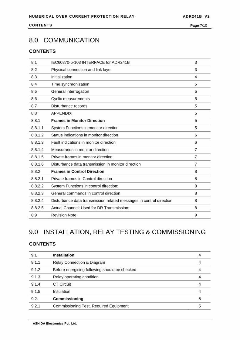
8.0 COMMUNICATION CONTENTS
8.1 IEC60870-5-103 INTERFACE for ADR241B 3
8.2 Physical connection and link layer 3
8.3 Initialization 4
8.4 Time synchronization 5
8.5 General interrogation 5
8.6 Cyclic measurements 5
8.7 Disturbance records 5
8.8 APPENDIX 5
8.8.1 Frames in Monitor Direction 5
8.8.1.1 System Functions in monitor direction 5
8.8.1.2 Status indications in monitor direction 6
8.8.1.3 Fault indications in monitor direction 6
8.8.1.4 Measurands in monitor direction 7
8.8.1.5 Private frames in monitor direction 7
8.8.1.6 Disturbance data transmission in monitor direction 7
8.8.2 Frames in Control Direction 8
8.8.2.1 Private frames in Control direction 8
8.8.2.2 System Functions in control direction: 8
8.8.2.3 General commands in control direction 8
8.8.2.4 Disturbance data transmission related messages in control direction 8
8.8.2.5 Actual Channel: Used for DR Transmission: 8
8.9 Revision Note 9
9.0 INSTALLATION, RELAY TESTING & COMMISSIONING CONTENTS
9.1 Installation 4
9.1.1 Relay Connection & Diagram 4
9.1.2 Before energising following should be checked 4
9.1.3 Relay operating condition 4
9.1.4 CT Circuit 4
9.1.5 Insulation 4
9.2. Commissioning 5
9.2.1 Commissioning Test, Required Equipment 5

NUMERICAL OVER CURRENT PROTECTION RELAY ADR241B_V2 CONTENTS
ASHIDA Electronics Pvt. Ltd.
Page 8/10 9.2.2 Checking of External Circuitry 5
9.2.2.1 Relay Back Terminal Wiring 5
9.2.2.2 Visual Inspection 5
9.2.2.3 Earthing 6
9.2.2.4 CT Polarity 6
9.2.3 Checking of Relay Setting 6
9.2.4 Final Checking 7
9.2.5 Commissioning Record Sheet 7
9.2.5.1 Relay identification 7
9.2.5.2 Commissioning Test Report 8
9.2.5.3 Commissioning record sheet for ADR241B_V2 Relay. 9
9.3 Post instillation / Commissioning observation 10
9.4 Testing of Relay 10
9.4.1 Relay Calibration 10
9.4.2 Diagram for Pickup and Timing Test 12
9.4.3 Testing of Over Current IP>> Protection 13
9.4.3.1 Pickup Test for Over Current IP>> 13
9.4.3.2 IDMT Time Test for Over Current IP>> 13
9.4.3.3 Pickup Test for Over Current Instantaneous Element IP>> 15
9.4.3.4 Operating Time Test for Over Current Instantaneous Element IP>> 16
9.4.4 Testing of 3Io>> Protection 16
9.4.4.1 Pickup Test for 3Io >> 16
9.4.4.2 IDMT Time Test for 3Io>> 17
9.4.4.3 Operating Time Test for Instantaneous Element 3Io>> 18
9.4.5 Testing of Earth Fault Ie>> Element 19
9.4.5.1 Pickup Test for Earth Fault Ie>> 19
9.4.5.2 IDMT Time Test for Earth Fault Ie>> 19
9.4.5.3 Operating Time Test for Earth Fault Instantaneous Element Ie>> 21
9.4.6 Testing of NPS (Negative Phase Sequence Element) 21
9.4.7 Testing of Annunciation for Both Over Current & Earth Fault 22
9.5 Other Functional Test 23
9.6 Revision Note 24

NUMERICAL OVER CURRENT PROTECTION RELAY ADR241B_V2 CONTENTS
ASHIDA Electronics Pvt. Ltd.
Page 9/10
10.0 PERIODIC TESTING CONTENTS 10 Periodic Testing 3
10.1 Trip Test 3
10.2 Functional Test 3
10.3 Testing of Relay 3
10.3.1 Relay Calibration 3
10.3.2 Diagram for Pickup and Timing Test 5
10.3.3 Testing of Over Current Protection 6
10.3.3.1 Pickup Test for Over Current 6
10.3.3.2 IDMT Time Test for Over Current 6
10.3.3.3 Testing of HF Pickup for Over Current Test 8
10.3.3.4 Operating Time test of HF for Over Current 9
10.3.4 Testing Of Earth Fault Current Protection 9
10.3.4.1 Testing of 3IO element 9
10.3.4.2 IDMT test for 3IO>> 10
10.3.4.3 Operating time test of HF for 3IO 11
10.3.4.4 Testing of EF element 12
10.3.4.5 IDMT time test for Ie >> 12
10.3.4.6 Operating Time test of HF for EF 14
10.3.4.7 Testing of NPS 14
10.3.5 Testing Of Annunciation For Both O/C and EF 14
10.3.6 Other functional tests 15
10.4 Revision Note 16
11.0 Details of Internal Circuit Diagram CONTENTS 11.1 Detail of Internal Circuit diagram 3
11.2 Revision Note 4
12.0 Problems Occurred & Hardware Software Revision CONTENTS
12.1 Problems Occurred 3
12.2 Hardware / Software Revision 3
12.3 Revision Note 5

NUMERICAL OVER CURRENT PROTECTION RELAY ADR241B_V2 CONTENTS
ASHIDA Electronics Pvt. Ltd.
Page 10/10
Revision Note
Issue Date Description
01 06.05.2008 Original Version
02 15.11.2008 Minor Typo Error Corrected

NUMERICAL OVER CURRENT PROTECTION RELAY ADR241B_V2 SAFETY INSTRUCTION
ASHIDA Electronics Pvt. Ltd. Ref: Manual/ADR241B_V2/Safety Issue: 02 Date : 15.11.08
Page 1/6
SAFETY INSTRUCTION

NUMERICAL OVER CURRENT PROTECTION RELAY ADR241B_V2 SAFETY INSTRUCTION
ASHIDA Electronics Pvt. Ltd. Ref: Manual/ADR241B_V2/Safety Issue: 02 Date : 15.11.08
Page 2/6
CONTENTS
1.1 Introduction 3
1.2 Healthy & Safety 3
1.3 Symbol & External Labels 4
1.4 Decommissioning & Disposal 4
1.5 Technical Specifications For Safety 5
1.5.1 Protective Fuse Rating 5
1.5.2 Protective Class 5
1.5.3 Installation Category 5
1.5.4 Environment 5
1.6 CE Marking 5
1.7 Revision Note 6

NUMERICAL OVER CURRENT PROTECTION RELAY ADR241B_V2 SAFETY INSTRUCTION
ASHIDA Electronics Pvt. Ltd. Ref: Manual/ADR241B_V2/Safety Issue: 02 Date : 15.11.08
Page 3/6 1.1 INTRODUCTION
This guide and the relevant operating or service manual documentation for the equipment
provide full information on safe handling, commissioning and testing of this equipment and
also includes description of equipment label markings.
Documentation for equipment ordered from ASHIDA Electronics Pvt. Ltd. is dispatched
separately from manufacture goods and may not be received at the same time. Therefore this
guide is provided to ensure that printed information normally present on equipment is fully
understood by the recipient.
Reference should be made to the external connection diagram before the equipment is
installed, commissioned or serviced.
1.2 HEALTHY AND SAFETY
This information in the Safety Section of the equipment documentation is intended to ensure
that equipment is properly installed and handled in order to maintain it in a safe condition.
It is assumed that everyone who will be associated with the equipment will be familiar with the
contents of that Safety Section, or this Safety Guide.
When electrical equipment is in operated, dangerous voltages will be present in certain parts
of the equipment. Failure to warning notices, incorrect use, or improper use may endanger
personnel and equipment and cause personal injury or physical damage.
Before working in the terminal strip area, the equipment must be isolated.
Proper and safe operation of the equipment depends on appropriate shipping and handling,
proper storage, installation and commissioning and on careful operation, maintenance and
servicing. For this reason only qualified personal may work on or operate the equipment.
Qualified personnel are individuals who
• Are familiar with the installation, commissioning and operation of the equipment and of the system to which it is being connected.
• Are able to safely perform switching operation in accordance with accepted safety
and to isolate ground and label it.
• Are trained in the care and use of safety apparatus in accordance with safety engineering practices.
• Are trained in emergency procedures (first aid)

NUMERICAL OVER CURRENT PROTECTION RELAY ADR241B_V2 SAFETY INSTRUCTION
ASHIDA Electronics Pvt. Ltd. Ref: Manual/ADR241B_V2/Safety Issue: 02 Date : 15.11.08
Page 4/6
The operating manual for the equipment gives instruction for its installation, commissioning
and operation. However, the manual cannot cover all conceivable circumstances or include
detailed information on all topics. In the event of questions or specific problems, do not take
any action without proper authorization. Contact the appropriate Ashida technical sales office
and request the necessary information
1.3 SYMBOLS AND EXTERNAL LABELS ON THE EQUIPMENT
For safety reasons the following symbols and external labels, which may be used on the
equipment or referred to in the equipment documentation, should be understood before the
equipment is installed or commissioned
Caution: refer to equipment documentation Caution: risk of electric shock
Protective Conductor (*Earth) terminal.
Functional/Protective Conductor Earth terminal
Note – This symbol may also be used for a Protective Conductor (Earth) terminal if that
terminal is part of a terminal block or sub-assembly e.g. power supply.
*NOTE: THE TERM EARTH USED THROUGHOUT THIS GUIDE IS THE 9ij DIRECT
EQUIVALENT OF THE NORTH AMERICAN TERM GROUND.
1.4 DECOMMISSIONING AND DISPOSAL
Decommissioning: The supply input (auxiliary) for the equipment may include capacitors across the
supply or to earth. To avoid electric shock or energy hazards, after completely
isolating the supplies to the equipment (both poles of any dc supply), the capacitors
should be safely discharged via the external terminals prior to decommissioning.
Disposal: It is recommended that incineration and disposal to water courses is avoided. The
equipment should be disposed of in a safe manner. Any equipment containing
batteries should have them removed before disposal, taking precautions to avoid
short circuits. Particular regulations within the country of operation, may apply to the
disposal of batteries.

NUMERICAL OVER CURRENT PROTECTION RELAY ADR241B_V2 SAFETY INSTRUCTION
ASHIDA Electronics Pvt. Ltd. Ref: Manual/ADR241B_V2/Safety Issue: 02 Date : 15.11.08
Page 5/6
1.5 TECHNICAL SPECIFICATIONS FOR SAFETY
1.5.1 Protective Fuse Rating The recommended maximum rating of the external protective fuse for equipments is 8A, high
rupture capacity (HRC) Red Spot type NIT, or TIA, or equivalent, unless otherwise stated in
the technical data section of the equipment documentation. The protective fuse should be
located as close to the unit as possible.
DANGER -CTs must NOT be fused since open circuiting them may produce lethal hazardous voltages. 7.2 Protective Class
1.5.2 Protective Class
IEC 61010-1: 2001 EN 61010-1: 2001
Class I (unless otherwise specified in the equipment documentation). This equipment requires a protective conductor (earth) connection to ensure user safety.
1.5.3 Installation Category
IEC 61010-1: 2001 EN 61010-1: 2001
Installation Category III (Over voltage Category III): Distribution level, fixed installation. Equipment in this category is qualification tested at 5kV peak, 1.2/50µs, 500Ω, 0.5J, between all supply circuits and earth and also between independent circuits
1.5.4 Environment
The equipment is intended for indoor installation and use only. If it is required for use in an
outdoor environment then it must be mounted in a specific cabinet or housing which will
enable it to meet the requirements of IEC 60529 with the classification of degree of protection
IP54 (dust and splashing water protected).
1.6 CE MARKING
Compliance with all relevant European Marking Community directives:
Compliance demonstrated by reference to safety standards.
Product safety: Low Voltage Directive - 73/23/EEC amended by 93/68/EEC EN 61010-1: 2001 EN 60950-1: 2001 EN 60255-5: 2001 IEC 60664-1: 2001

NUMERICAL OVER CURRENT PROTECTION RELAY ADR241B_V2 SAFETY INSTRUCTION
ASHIDA Electronics Pvt. Ltd. Ref: Manual/ADR241B_V2/Safety Issue: 02 Date : 15.11.08
Page 6/6
1.7 Revision Note
Issue Date Description
01 06.05.2008 Original Version
02 15.11.2008 Typo Error Corrected
NUMERICAL OVER CURRENT PROTECTION RELAY ADR241B_V2 INTRODUCTION
ASHIDA Electronics Pvt. Ltd. Ref: Manual/ADR241B_V2/Introduction Issue: 02 Date : 15.11.2008
Page 1/9
INTRODUCTION

NUMERICAL OVER CURRENT PROTECTION RELAY ADR241B_V2 INTRODUCTION
ASHIDA Electronics Pvt. Ltd. Ref: Manual/ADR241B_V2/Introduction Issue: 02 Date : 15.11.2008
Page 2/9 CONTENTS
2.1 General 3
2.2 Features 4
2.3 How to use the Manual 5
2.4 Ordering Information 7
2.5 Revision Note 9

NUMERICAL OVER CURRENT PROTECTION RELAY ADR241B_V2 INTRODUCTION
ASHIDA Electronics Pvt. Ltd. Ref: Manual/ADR241B_V2/Introduction Issue: 02 Date : 15.11.2008
Page 3/9
2.1. General Features of Aditya-V2 Series : -
ADR241B is a second generation Numerical 3OC + 1EF Over Current Relay. The ADR241B
is part of Ashida Aditya Series ( Aditya-V2 ) of protective relays. General definition and
Aditya series and it model number is give in ordering information.
All the relay are designed using latest numerical technology and having programmable digital
input and outputs to minimized external contact multiplication electromechanical relays. All
relays are tested for EMI / EMC noise as per international IEC specifications. The basic
electronics hardware is common for all relays. The user interface for all relay are similar only
protection logic is different, this make very easy to use. General features of all relays are as
given below
• Large 20x4 LCD display
• Password Protection for all setting
• Disturbance Recorder. Actual waveform of current are captured & saved in the built-in
memory with date time stamping, for analyzing fault condition & fault location.
• IEC standard open protocol.
• Separate Communication Prot for SCADA (RS485) as well as Local testing (RS232)
• Very low burden on CT and PT
• Online display current other digital and physical status.
• Continuous monitoring of module’s internal hardware and alarm generation in case of
failure of any critical components.
• 10 Digital Output contacts for local alarm Tele-signalling & Control
• 7 Optically isolated digital status input for monitoring of status and avoid used of external
relay logic
• 100 nos of event memory, event such CB close, Trip, status change, relay pkp etc. All
events are with date and time stamped up to 1ms
• 6 Programmable ( 3 Red / 3 Green) LED which can be assigned to any of protection
function
• 5 Programmable Relay which can be programmed through key board.
• 5 Optically isolated status input

NUMERICAL OVER CURRENT PROTECTION RELAY ADR241B_V2 INTRODUCTION
ASHIDA Electronics Pvt. Ltd. Ref: Manual/ADR241B_V2/Introduction Issue: 02 Date : 15.11.2008
Page 4/9
The ADR241B is a 3 Over Current and 1 EF relay it consist all the necessary protection and
monitoring functions required for Normal feeder it consist of
1. High Speed Digital DSP Controller
2. Analog Measuring Module
3. Power supply Module
4. Digital Input output module. The High speed Digital Signal Controller continuously monitors line phase current and E/F
current. Along with different status input, through CTs, and optical isolated status
connections. The high-speed micro-controller samples these current signals through a A/D converter. The Digital Signal performs powerful Numerical Algorithms to find out RMS of
fundamental & harmonic contents of the current. All measurement is tuned to fundamental
frequency i.e 50Hz, thus relay remain stable during distorted waveform generated electronics
loco-motive. All these measure values are then used for different protection function such as
IDMT Over current protection, Instantaneous Over current protection, E/F protection etc.
These measured values are also displayed on large 20 x 4 LCD display for metering purpose.
The DSC also monitor different digital input trough optical isolator and perform some
monitoring function such trip circuit supervision, and control potential free contact for control
CB and generate ALARM and Tele-signalling
The power supply module is basically DC – DC converted designed using modern PWM
based Switching mode technique to convert 110Vdc station battery supply to the 12V and
24Vdc low voltage supply for relay electronics and control circuit. It also provides necessary
isolation from station battery. There are two type of power supply modules are available 1)
having range of 77Vdc – 250Vdc. Covering requirement of 110Vdc and 220Vdc station
battery system 2) having range of 18Vdc to 52Vdc covering 24Vdc, 30Vdc, 48Vdc station
battery requirement.
The relay is having total 8 nos of dual LED of high intensity for easy identification of type of
fault for easy user interface. LEDs L5, L6 and L7 and Relay R1 to R5, digital status input and
controlled output are fully programmable via key pad interface.
2.2. Features : -
Protection Features:
4 Element (3 Phase + EF) Over current IDMT/DMT with instant trip.
Programmable (Non- Volatile) Setting By local keys as well as remote setting by
communication port

NUMERICAL OVER CURRENT PROTECTION RELAY ADR241B_V2 INTRODUCTION
ASHIDA Electronics Pvt. Ltd. Ref: Manual/ADR241B_V2/Introduction Issue: 02 Date : 15.11.2008
Page 5/9
Selection of Curve: Five selectable curve (Normal Inverse 1 (C1), Normal Inverse 2, (C2)
Very inverse (C3), Extremely inverse (C4), Long time inverse (C5)) and Define Time
(C6).
Instantaneous Over-Current Protection with adjustable timer.
Breaker Failure detection.
In-built CB Trip Circuit Supervision function during pre closing and post closing of CB.
Negative sequence over current (46).
2.3. HOW TO USE THE MANUAL
This manual contain detail information of “ADITYA” series over current and earth fault relay such as ADR241B by using this manual user can be familiar with the application, installation setting & commissioning of these relays. The User Interface and Menu will be different for different software version. The user interface chapter describe latest software version relay. The older relay menus are shown in menu tables. Before referring manual first identify your relay software version. The software version can be found by following procedure After Power ON or when the HW RESET and LED RESET push button is pressed simultaneously, the relay will display the following message. 1. Safety instruction : -
Content of this chapter is regarding safety of human being to operate/handle this relay.
2. Introduction : - Content of this chapter is about general introduction to the ”ADITYA” series of ADR range of relays.
3. Handling : - Content of this chapter is regarding precaution to be taken while handling electronic equipment.
4. User Guide : - A detail description of features of “ADITYA” series relays.
5. Menu content Table : - This chapter contain detail flash chart of relay as per software history.
6. Technical Specification : - Comprehensive details on nominal values setting ranges, specification & curve characteristics.
Ashida Numerical 3OC/1EF IDMT Relay ADR241B_V2_R2 V02.01 Unit ID = 0001
This window will flash momentarily showing the following Relay Name : 3OC/1EF IDMT Relay Relay Type : ADR241B_V2_R2 Software Version : V02.01 Unit ID = 0001 Then the control will go automatically to default window

NUMERICAL OVER CURRENT PROTECTION RELAY ADR241B_V2 INTRODUCTION
ASHIDA Electronics Pvt. Ltd. Ref: Manual/ADR241B_V2/Introduction Issue: 02 Date : 15.11.2008
Page 6/9
7. Application Guide : - This chapter contains detail description of each relay setting guidelines.
8. Communication : - Communication setting & Protocol details.
9. Installation, Relay Testing & Commissioning : - This chapter contains information regarding installation; complete functional testing of relay & commissioning data sheet.
10. Periodic Testing : - This chapter contains periodic relay testing information.
11. Details of Internal Assemblies : - Information regarding relays internal assemblies.
12. Problem Occurred and Hardware & Software Revision : - Information regarding Error Codes and Hardware & Software Revisions.
NUMERICAL OVER CURRENT PROTECTION RELAY ADR241B_V2 INTRODUCTION
ASHIDA Electronics Pvt. Ltd. Ref: Manual/ADR241B_V2/Introduction Issue: 02 Date : 15.11.2008
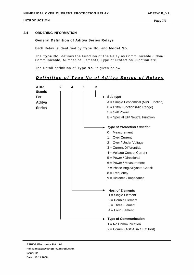
Page 7/9 2.4 ORDERING INFORMATION
General Definit ion of Aditya Series Relays
Each Relay is ident i f ied by Type No . and Model No .
The Type No. def ines the Funct ion of the Relay as Communicable / Non-Communicable, Number of Elements, Type of Protect ion Funct ion etc.
The Detai l def in it ion of Type No . is given below.
D e f i n i t i o n o f T y p e N o o f A d i t y a S e r i e s o f R e l a y s ADR 2 4 1 B Stands For Aditya Series
Type of Protection Function 0 = Measurement 1 = Over Current 2 = Over / Under Voltage 3 = Current Differential. 4 = Voltage Control Current 5 = Power / Directional 6 = Power / Measurement 7 = Phase Angle/Syncro-Check 8 = Frequency 9 = Distance / Impedance
Nos. of Elements 1 = Single Element 2 = Double Element 3 = Three Element 4 = Four Element
Type of Communication 1 = No Communication 2 = Comm. (ASCADA / IEC Port)
Sub type A = Simple Economical (Mini Function) B = Extra Function (Mid Range) S = Self Power E = Special EF/ Neutral Function

NUMERICAL OVER CURRENT PROTECTION RELAY ADR241B_V2 INTRODUCTION
ASHIDA Electronics Pvt. Ltd. Ref: Manual/ADR241B_V2/Introduction Issue: 02 Date : 15.11.2008
Page 8/9
Ordering information:
A D R 2 4 1 B - A M - X X X - X X - X - X - X X - X
Example ADR241B – AM-201-01-3-0-02-0 Type: ADR241B wi th s tandard set t ing IEC60870-5-103 com St . Back termina l layout Cabinet Type: CSE -150 H Aux i l ia ry Supply: 77-250Vdc CT sec: 1 Amp. / 5 Amp selectable
D e f i n i t i o n o f M o d e l N o o f A d i t y a S e r i e s o f R e l a y s A M 2 0 1 – X X – X – X – X X – X
Auxiliary Supply 01 = 18 – 52 V dc 06 = 110 V dc 02 = 77 – 250 V dc 07 = 220 V dc 03 = 24 V dc 04 = 30 V dc 05 = 48 V dc
Reserved for Future Use
PT Secondary0 = NA 1 = 63.5V ac 2 = 110V ac 3 = 230V ac
CT Secondary 1 = 1 Amp. 2 = 5 Amp. 3 = 1 Amp. / 5 Amp. Selectable
201 indicates Aditya _V2 This Document – For Other model Refer respective document or contact Factory
Back Terminal Lay out 01 = As Per ADV00101 and Cabinet as MAC01302

NUMERICAL OVER CURRENT PROTECTION RELAY ADR241B_V2 INTRODUCTION
ASHIDA Electronics Pvt. Ltd. Ref: Manual/ADR241B_V2/Introduction Issue: 02 Date : 15.11.2008
Page 9/9
2.5 Revision Note
Issue Date Description
01 06.05.2008 Original Version
02 15.11.2008 Typo Error Corrected

NUMERICAL OVER CURRENT PROTECTION RELAY ADR241B_V2 HANDLING
ASHIDA Electronics Pvt. Ltd. Ref: Manual/ADR241B_V2/Handling Issue: 02 Date : 15.11.2008
Page 1/6
HANDLING AND CASE DIMENSION

NUMERICAL OVER CURRENT PROTECTION RELAY ADR241B_V2 HANDLING
ASHIDA Electronics Pvt. Ltd. Ref: Manual/ADR241B_V2/Handling Issue: 02 Date : 15.11.2008
Page 2/6
CONTENTS
3 Handling 3
3.1 Receipt of Relay 3
3.2 Unpacking 3
3.3 Handling of Electric Components 3
3.4 Storage 4
3.5 Dimensions 4
3.5.1 Connections of Power Terminals and Signal Terminals 4
3.5.2 Earthing 4
3.6 Cabinet drawing 5
3.7 Revision Note 6
NUMERICAL OVER CURRENT PROTECTION RELAY ADR241B_V2 HANDLING
ASHIDA Electronics Pvt. Ltd. Ref: Manual/ADR241B_V2/Handling Issue: 02 Date : 15.11.2008
Page 3/6
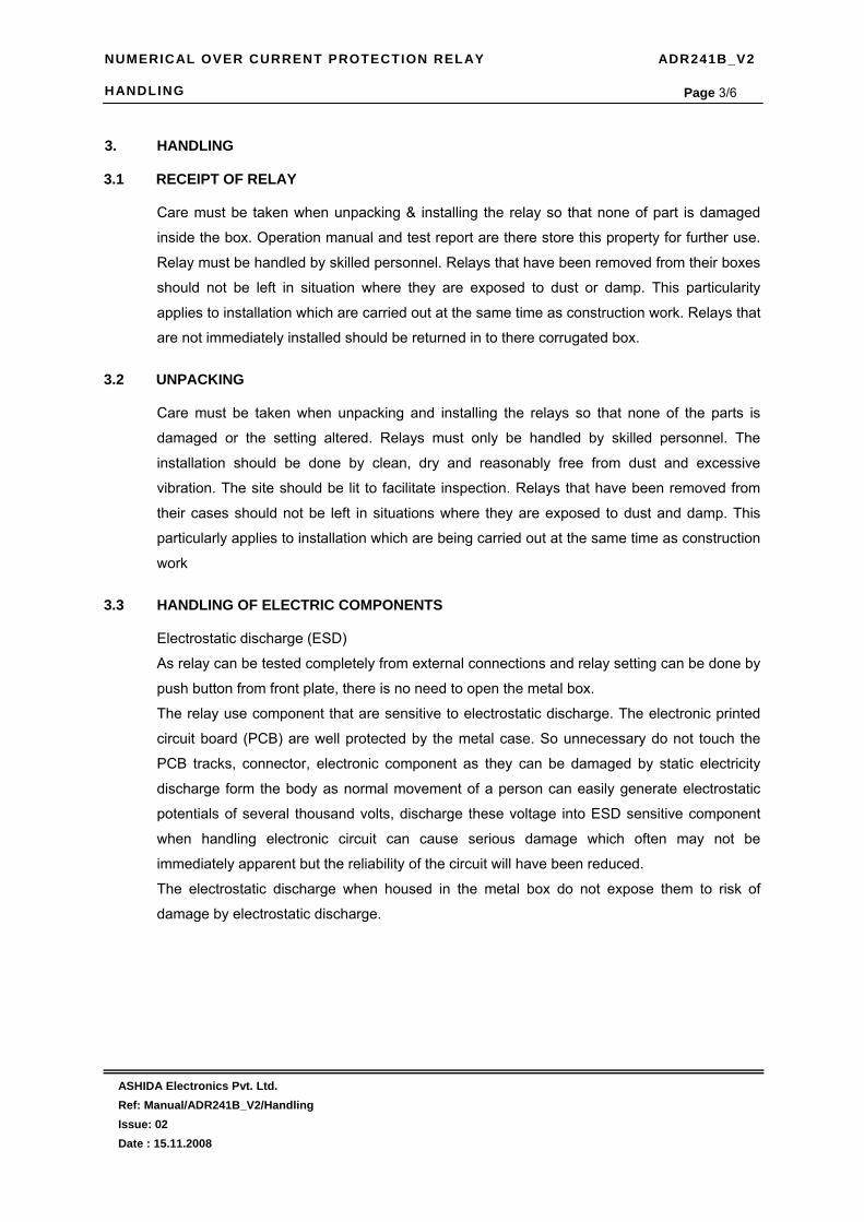
3. HANDLING
3.1 RECEIPT OF RELAY
Care must be taken when unpacking & installing the relay so that none of part is damaged
inside the box. Operation manual and test report are there store this property for further use.
Relay must be handled by skilled personnel. Relays that have been removed from their boxes
should not be left in situation where they are exposed to dust or damp. This particularity
applies to installation which are carried out at the same time as construction work. Relays that
are not immediately installed should be returned in to there corrugated box.
3.2 UNPACKING
Care must be taken when unpacking and installing the relays so that none of the parts is
damaged or the setting altered. Relays must only be handled by skilled personnel. The
installation should be done by clean, dry and reasonably free from dust and excessive
vibration. The site should be lit to facilitate inspection. Relays that have been removed from
their cases should not be left in situations where they are exposed to dust and damp. This
particularly applies to installation which are being carried out at the same time as construction
work
3.3 HANDLING OF ELECTRIC COMPONENTS
Electrostatic discharge (ESD)
As relay can be tested completely from external connections and relay setting can be done by
push button from front plate, there is no need to open the metal box.
The relay use component that are sensitive to electrostatic discharge. The electronic printed
circuit board (PCB) are well protected by the metal case. So unnecessary do not touch the
PCB tracks, connector, electronic component as they can be damaged by static electricity
discharge form the body as normal movement of a person can easily generate electrostatic
potentials of several thousand volts, discharge these voltage into ESD sensitive component
when handling electronic circuit can cause serious damage which often may not be
immediately apparent but the reliability of the circuit will have been reduced.
The electrostatic discharge when housed in the metal box do not expose them to risk of
damage by electrostatic discharge.

NUMERICAL OVER CURRENT PROTECTION RELAY ADR241B_V2 HANDLING
ASHIDA Electronics Pvt. Ltd. Ref: Manual/ADR241B_V2/Handling Issue: 02 Date : 15.11.2008
Page 4/6 3.4 STORAGE
If relays are not to be installed immediately upon receipt they should be stored in a place free from dust and moisture in their original cartons. Where de-humidifier crystals will be impaired if the bag has been exposed to ambient conditions and may be restored by gently heating the bag for about an hour, prior to replacing it in the carton Dust which collect on a carton may, on subsequent unpacking find its way into the relay, in damp conditions the carton and packing may become Impregnated with moisture and the de-humidifier will lose its efficiency. Storage temperature: -25°C to +70°C
3.5 DIMENSIONS
3.5.1 Connection of power terminals, and Signals terminals
The individual equipment are delivered with sufficient M4 screws to connect the relay via annular terminals, with a maximum recommended of two annular terminals per contact. To insure the insulation of the terminals and to respect the security and safety instructions, an isolated sleeve can be used. We recommend the following cable cross-sections: − Auxiliary sources Vaux : 1.5 mm² (some electrical utiliets use 2.5 mm2 ) − Communication Port – D9 Femel with 0.5 mm2 per core total 4 core screen. The maximum
length of 1000m. Linear capacitance between conductor and earth : 100pF/m − PT Circuit 1.5 mm2 − Other circuits 1.0 mm² − CT Circuit 4 - 6 mm2 We recommend to protect the auxiliary source connection by using a fuse of type NIT or TIA with a breaking capacity of 16A. For security reasons, do never install fuses in current Transformers circuits. The other circuits must be protected by fuses.
3.5.2 Earthing Each equipment must be connected to a local earth terminal by the intermediary of a M4 earth terminals. We recommend a wire of minimal section of 2,5 mm², connected to cabinet bolt . Because of the limitations of the annular terminals, NOTE : To prevent any electrolytic risk between copper conductor or brass conductor and the back plate of the equipment, it is necessary to take precautions to isolate them one from the other. This can be done in several ways, for example by inserting between the conductor and the case a plated nickel or insulated ring washer or by using a tin terminals.


NUMERICAL OVER CURRENT PROTECTION RELAY ADR241B_V2 HANDLING
ASHIDA Electronics Pvt. Ltd. Ref: Manual/ADR241B_V2/Handling Issue: 02 Date : 15.11.2008
Page 6/6
3.7 Revision Note
Issue Date Description
01 06.05.2008 Original Version
02 15.11.2008 Typo Error Corrected

NUMERICAL OVER CURRENT PROTECTION RELAY ADR241B_V2 USER’S GUIDE
ASHIDA Electronics Pvt. Ltd. Ref: Manual/ADR241B_V2/User_Guide Issue: 02 Date : 15.11..2008
Page 1/95
USER’S GUIDE (For Software V2.xx)

NUMERICAL OVER CURRENT PROTECTION RELAY ADR241B_V2 USER’S GUIDE
ASHIDA Electronics Pvt. Ltd. Ref: Manual/ADR241B_V2/User_Guide Issue: 02 Date : 15.11..2008
Page 2/95
CONTENTS
4.1 Front Panel and Control 5
4.2 User’s Interface 7
4.2.1 LCD Display 7
4.2.2 Touch Keys 7
4.2.3 LED’s 8
4.2.4 RS485 8
4.2.5 RS232 8
4.3 Password 9
4.3.1 Password Entry & Changing the Password 9
4.3.2 Clear Password 10
4.3.3 Default Settings 11
4.3.3.1 General Settings 11
4.3.3.2 Protection Settings 12
4.4 Menus 15
4.4.1 Default Display 15
4.4.2 Main Menu List 16
4.4.2.1 Main Menu List Details 17
4.4.3 Measurement 23
4.4.3.1 To View - Measurement 23
4.4.4 General Setting 24
4.4.4.1 To Set – General Setting 24
4.4.4.2 To View – General Setting 28
4.4.5 Over Current (OC-G1) Setting 29
4.4.5.1 To Set – OC-G1 Setting 29
4.4.5.2 To View – OC-G1 Setting 32
4.4.6 Earth Fault (EF-G1) Setting 33
4.4.6.1 To Set – EF-G1 Setting 33
4.4.6.2 To View – EF-G1 Setting 36
4.4.7 3Io-G1 Setting 37
4.4.7.1 To Set – 3Io-G1 Setting 37
4.4.7.2 To View – 3Io-G1 Setting 40
4.4.8 Negative Phase Sequence Element (NPS-G1) Setting 41
4.4.8.1 To Set – NPS-G1 Setting 41
4.4.8.2 To View – NPS-G1 Setting 43

NUMERICAL OVER CURRENT PROTECTION RELAY ADR241B_V2 USER’S GUIDE
ASHIDA Electronics Pvt. Ltd. Ref: Manual/ADR241B_V2/User_Guide Issue: 02 Date : 15.11..2008
Page 3/95
4.4.9 Over Current (OC-G2) Setting 44
4.4.9.1 To Set – OC-G2 Setting 44
4.4.9.2 To View – OC-G2 Setting 47
4.4.10 Earth Fault (EF-G2) Setting 48
4.4.10.1 To Set – EF-G2 Setting 48
4.4.10.2 To View – EF-G2 Setting 51
4.4.11 3Io-G2 Setting 52
4.4.11.1 To Set – 3Io-G2 Setting 52
4.4.11.2 To View – 3Io-G2 Setting 55
4.4.12 Negative Phase Sequence Element (NPS-G2) Setting 56
4.4.12.1 To Set – NPS-G2 Setting 56
4.4.12.2 To View – NPS-G2 Setting 58
4.4.13 Auto Recloser (ARR) Setting 59
4.4.13.1 To Set – ARR Setting 59
4.4.13.2 To View – ARR Setting 61
4.4.14 Relay/LED Configuration 62
4.4.14.1 Bit Definition for Relay/LED Configuration 62
4.4.14.2 List of Protection Function and Digital Inputs 63
4.4.14.3 To Set – Relay/LED Configuration 67
4.4.14.4 To View – Relay/LED Configuration 72
4.4.14.5 Example of Relay / LED Configuration 73
4.4.15 Fault 1 88
4.4.15.1 To View – Fault 1 Data [Fault 2 to Fault 20] 88
4.4.16 Status 89
4.4.16.1 To View – Status 89
4.4.17 Error Log 89
4.4.17.1 To View – Error Log 89
4.4.18 Close 90
4.4.19 Trip 90
4.4.20 Active Group 91
4.4.20 Date Time Setting 92
4.4.20.1 To Set – Date Time setting 92
4.4.20.2 To View – Date Time Setting 93

NUMERICAL OVER CURRENT PROTECTION RELAY ADR241B_V2 USER’S GUIDE
ASHIDA Electronics Pvt. Ltd. Ref: Manual/ADR241B_V2/User_Guide Issue: 02 Date : 15.11..2008
Page 4/95
4.5 Input Signals 94
4.5.1 Auxiliary Supply Input 94
4.5.2 CT Secondary Input 94
4.5.3 Status Input 94
4.5.4 Trip Circuit Supervision Input 94
4.6 Output Signals 94
4.6.1 Trip Contact 94
4.6.2 Programmable Contact 94
4.6.3 LBB Protection Contact 94
4.6.4 Relay ( OK ) Healthy Contact 94
4.6.5 Auto Recloser ‘Reclose’ Contact 94
4.6.6 Auto Recloser Lockout Contact 94
4.6.7 Control Contact selectable 94
4.7 Revision Note 95

NUMERICAL OVER CURRENT PROTECTION RELAY ADR241B_V2 USER’S GUIDE
ASHIDA Electronics Pvt. Ltd. Ref: Manual/ADR241B_V2/User_Guide Issue: 02 Date : 15.11..2008
Page 5/95
4.1. Front Panel and Control
1
2
3
4
6
5
7 9 10 11 12 13
8 14
11
22
33
44
66
555
777 999 10 1111 1212 1313
88 1414
Sr. No. Legend Description LEDs Total 8 dual colours LED (Red and Green) are provided for
user interface. The some of LEDs are pre defined. While some are spare and can be programmed as per the requirement. Following are fix LED
1 PROTH / ERR Protection Healthy This is a green LED and become off in flowing condition. During Error It become Red
a When Auxiliary supply is not sufficient to operate relay.
b Relay detect some internal hardware error (LED will become RED)
c When there Trip circuit is faulty (LED will become RED)
2 FAULT / PKP – Green LED indicates FAULT condition. This is Hand Reset (HR) indication and remains on till Reset either by local switch or through communication
Red LED indicates Relay PICKUP condition This is Self Reset (SR) type. Indicates at least one of the current inputs is above set threshold.

NUMERICAL OVER CURRENT PROTECTION RELAY ADR241B_V2 USER’S GUIDE
ASHIDA Electronics Pvt. Ltd. Ref: Manual/ADR241B_V2/User_Guide Issue: 02 Date : 15.11..2008
Page 6/95
3 DT / REC Green LED indicates Dead Time Red LED indicate Reclaim time
4 LOCK / BF Green LED indicates ARR lock-out Hand Reset (HR) Type. Red LED indicates Breaker Fail Hand Reset (HR) Type.
5 ARR. E / ARR.D Green LED indicates ARR Enable Red LED indicates ARR Disable (Note : The above function can be assigned to this LED after loading default Setting)
6 L6 / L7 Spare LED Programmable 7 TRIP / CLOSE Green LED indicates Output TRIP Relay contact closer
(Self Reset SR) Type Red LED indicate Output CLOSE Relay contact closer Self Reset (SR) Type
8 LCD display A 20 character by 4 line back-lit large LCD display will be provided for display of setting / status and measured value such as line current etc.
9 LED Reset 1 Key will be provided for LED reset
10 TEST 1 key will be provided for Trip test. This key could be blocked through general setting, if required.
11 ARR 1 Key will be provided to Enable/Disable ARR (Auto Recloser Relay) function.
12 HW Reset 1 key will be provided for Hardware reset. This key will be interlocked with LED reset.
13 Navigation Key 4 keys will be provided for navigation through different display menu and to do setting
14 Cover This is a removable cover. After removing this cover, local communication port (RS232) will be accessible.

NUMERICAL OVER CURRENT PROTECTION RELAY ADR241B_V2 USER’S GUIDE
ASHIDA Electronics Pvt. Ltd. Ref: Manual/ADR241B_V2/User_Guide Issue: 02 Date : 15.11..2008
Page 7/95
4.2. USER INTERFACE 4.2.1. LCD Display
Back-lit LCD display 20 x 4 is provided for parameter and setting display and for easy viewing of measurement, setting, fault records, date & time, error message. Back-lit will automatically switch off if any push button key will not be pressed for more than 100sec. The display back-lit can be made on by pressing any push button key. Back-lit is also automatically turned on when any tripping occurs on particular equipment.
4.2.2. Touch Keys
The function of relay is controlled by the following keys, Left Arrow key ( ), Right Arrow key ( ), Up Arrow key ( ) Down Arrow key ( ) and LED Reset Key, Test Key, Bypass Key and HW Reset Key which are provided on the front Plate. • When the Right Arrow key ( ) is pressed the operator is able to view the setting of the
relay. When the Right Arrow key ( ) is pressed again it will go to the next setting page, but in case there are no more setting to be displayed it returns to the main menu.
• When the Left Arrow key ( ) is pressed than you can return to previous display page, it relay is already on main menu then, you are able to enter the setting which can be now modified using Up Arrow key ( ) Down Arrow key ( ). When the Left Arrow key ( ) pressed again it will go to the next setting.
• The Up Arrow key ( ) is used to increment the value, the Down Arrow key ( ) is used to decrement the value in the display.
• The Left Arrow key ( ) Right Arrow key ( ) can be used to go forward or backward, both when doing the settings and while viewing the settings
At the time of setting if changes are not carried within 100s then the display will reset it self and return to the main menu. Or you can discard setting and abort to main menu by pressing ‘LED RESET’ key ‘HW RESET’ key is never require in normal operation, It is series with ‘LED RESET’ key, When both keys are pressed simultaneously it reset total hardware of relay. This normally required during firmware update of relay.

NUMERICAL OVER CURRENT PROTECTION RELAY ADR241B_V2 USER’S GUIDE
ASHIDA Electronics Pvt. Ltd. Ref: Manual/ADR241B_V2/User_Guide Issue: 02 Date : 15.11..2008
Page 8/95
4.2.3. LED’s
The relay is having total 8 nos of dual LED of high intensity for easy identification of type of
fault for easy user interface. LEDs L6 and L7 are fully programmable via key pad interface as
these are bi-color LED effectively 6 LEDs are full programmable.
Sr. No. Legend Description 1 PROT.H /
ERR : Green LED indicates Relay OK (Protection Healthy) : In case of following condition led become Red 1. Problem in relay Hardware. 2. Trip Circuit Fault
2 FAULT / PICK-UP
: Green LED indicates FAULT Hand Reset (HR) Type. : Red LED indicate Start of timer Self Reset (SR) Type
3 DT / REC : Green LED indicate Dead Time : Red LED indicate Reclaim time
4 LOCK / BF
: Green LED indicate ARR lock-out (HR) Type : Red LED indicate Breaker Fail (HR) Type
5 ARR. E / ARR. D
Green LED indicates ARR Enable Red LED indicates ARR Disable (Note : The above function can be assigned to this LED after loading default Setting)
6 L6 : Spare LED Programmable 7 L7 : Spare LED Programmable 8 TRIP /
CLOSE : Green LED indicates Output Trip relay contact closer (SR) Type : Red LED indicate output Close relay contact closer (SR) Type
4.2.4. RS485 Port
RS485 port is provided at the back side of relay (near to terminal block) for permanent SCADA connectivity. The physical connection is through D9 type male connector, to avoid accentual connection power warring to communication input. There are 4 wire are used 2 for transmission and 2 for receiving. The actual connection diagram is given in communication section. Using RS485 port Fault data live event, disturbance record, etc can be downloaded port.
4.2.5. RS232 Port
RS232 Communication port D9 type male is provided on front panel of relay, after opening of front cover this port is available. This is very useful for down loading relay data and analysis it. For proper operation user must select communication port from keyboard (general setting) detail description is given in communication chapter.

NUMERICAL OVER CURRENT PROTECTION RELAY ADR241B_V2 USER’S GUIDE
ASHIDA Electronics Pvt. Ltd. Ref: Manual/ADR241B_V2/User_Guide Issue: 02 Date : 15.11..2008
Page 9/95
4.3. Password
4.3.1. Password Entry and changing the password
To enter password in all ADR241B_V2 refer following steps ( User can go to this screen by pressing HW RESET + LED RESET Simultaneously)
In ADR241B the password protected windows are 1. General Setting 2. OC – G1 Setting 3. EF – G1 Setting 4. 3Io – G1 Setting 5. NPS – G1 Setting 6. OC – G2 Setting 7. EF – G2 Setting 8. 3Io – G22 Setting 9. NPS – G2 Setting 10. ARR Setting 11. Relay LED Config and 12. Date Time Setting Procedure to enter the password is same for all windows to enter the password follow these
steps.
General Settings New Password = 000 Range 000-099 Use Inr/Dec
By using the up arrow key ( ) or the down arrow key ( ) New Password can be set. The range is from 000-099 in steps of 001. Press the arrow key ( ) the relay will display other windows on by one till the following window.
Measurement Using + / (INR) or - / (DEC) key scroll the main menu to go to General Setting
Secondary Current R = 000.00 Y = 000.00 B = 000.00 3Io=000.00 CT Sec. Selected = 1A
This is default window showing the actual Secondary Load Current as per “CT Sec” selection Press the arrow key ( ) the relay will display Main menu directly as follows.
Password = 001 Use Inr/Dec
Enter the previously set password, by using the up arrow key or the down arrow key ( ). Note : Default password setting is ‘000’ Press the arrow key ( ) the relay will display as follow.
→ General Settings ←
Password protected window for “General Setting’’ for setting New Password, language Selection, Unit ID, Baud Rate, Com Port, Set Parity, BF Enable, BF Delay, BF Cont,. CT Sec., CT EF, CT Primary, Local Control, Trip Ckt. Trip Cont., Active Group, Cold Load Pick_up. and EF Current Press the arrow key ( ) the relay will display as follow.

NUMERICAL OVER CURRENT PROTECTION RELAY ADR241B_V2 USER’S GUIDE
ASHIDA Electronics Pvt. Ltd. Ref: Manual/ADR241B_V2/User_Guide Issue: 02 Date : 15.11..2008
Page 10/95
4.3.2. Clear Password There are unlinking event when user forgot the password, in such case password can be
cleared by pressing following sequences
1) Press ‘HW RESET’ + ‘LED RESET’ Simultaneously, and hold both.
2) Press navigation key ( ) key Immediately and hold then release ‘HW RESET’ + ‘LED RESET’
3) Press and hold navigation key ( ) key until following message appear on display
Mode for Save? Save Settings
Now again press the ‘ ’ Left arrow key the ÓK’ window will appear for a moment and the control will automatically return to ‘’General Settings’
OK
General Setting
All Fault Memories, Password Clear & all protection OFF Press HW+LED Reset
This window will appear shows all fault memories and password are clear and default password was 0000. All protection function will disable and required to enable as per requirement.
Ashida Numerical 3OC/1EF IDMT Relay ADR241B_V2_R2 V02.08 Unit ID = 0001
This window will flash momentarily showing the following Relay Name : 3OC/1EF IDMT Relay Relay Type : ADR241B_V2_R2 Software Version : V02.01 Unit ID = 0001 Then the control will go automatically to following window

NUMERICAL OVER CURRENT PROTECTION RELAY ADR241B_V2 USER’S GUIDE
ASHIDA Electronics Pvt. Ltd. Ref: Manual/ADR241B_V2/User_Guide Issue: 02 Date : 15.11..2008
Page 11/95
4.3.3. Default Settings
4.3.3.1. General Settings
Index Settings Value Range 1 BF Enable 1 YES/NO
2 BF Delay 200mSec Range 200-1000ms
3 BF Cont 1 SR/HR
4 CT Sec. 2Amp 1Amp/5Amp
5 CT EF 2Amp 1Amp/5Amp
6 CT Primary 300 Range 10-2000
7 Local Control 2 YES/NO
8 Trip Ckt 2 YES/NO
9 Trip Cont 1 SR/HR
10 Active Group 1 G1/G2
11 Cold Ld PKP 2 Enable/Disable
12 RL1 H 14560 13 RL1 L 32768 14 RL2 H 50944 15 RL2 L 32769 16 RL3 H 0 17 RL3 L 0 18 RL4 H 0 19 RL4 L 0 20 RL5 H 0 21 RL5 L 0 22 L5 Green H 0 Special LED 23 L5 Green L 0 Special LED 24 L5 Red H 0 Special LED 25 L5 Red L 2 Special LED 26 L6 Green H 0 27 L6 Green L 32772 28 L6 Red H 0 29 L6 Red L 32770 30 L7 Green H 0 31 L7 Green L 0 32 L7 Red H 0 33 L7 Red L 0 34 S1 0 35 S2 0 36 S3 1 37 S4 2 38 S5 0

NUMERICAL OVER CURRENT PROTECTION RELAY ADR241B_V2 USER’S GUIDE
ASHIDA Electronics Pvt. Ltd. Ref: Manual/ADR241B_V2/User_Guide Issue: 02 Date : 15.11..2008
Page 12/95
4.3.3.2. Protection Settings
Index Settings Value Range 1 IP> Enable - G1 2 YES/NO 2 IP> 90% Range 10%-200%
3 IP> TMS 0.15 Range x0.02-x1.00
4 IP> Curve 6 C1-C6
5 IP> C6 Delay 0.01S 0-99.90S
6 IP>> Enable 1 YES/NO 7 IP>> 100% Range 10%-200%
8 IP>> TMS 0.15 Range x0.02-x1.00
9 IP>> Curve 1 C1-C6
10 IP>> C6 Delay 0.1S 0-99.90S
11 P>>> Enable 1 YES/NO 12 IP>>> 400% Range 50%-2000%
13 IP>>> Delay 0.1S 0-2.00S
14 EF > Enable - G1 2 YES/NO 15 EF > 20% Range 10%-200%
16 EF > TMS 0.02 Range x0.02-x1.00
17 EF > Curve 1 C1-C6
18 EF > C6 Delay 0.01S 0-99.90S
19 EF >> Enable 1 YES/NO 20 EF >> 80% Range 10%-200%
21 EF >> TMS 0.15 Range x0.02-x1.00
22 EF >> Curve 1 C1-C6
23 EF >> C6 Delay 0.1S 0-99.90S
24 EF >>> Enable 1 YES/NO 25 EF >>> 100% Range 50%-2000%
26 EF >>> Delay 0.1S 0-2.00S
27 3Io > Enable - G1 2 YES/NO 28 3Io > 20% Range 10%-200%
29 3Io > TMS 0.02 Range x0.02-x1.00
30 3Io > Curve 1 C1-C6
31 3Io > C6 Delay 0.01S 0-99.90S
32 3Io >> Enable 1 YES/NO 33 3Io >> 20% Range 10%-200%
34 3Io >> TMS 0.02 Range x0.02-x1.00
35 3Io >> Curve 1 C1-C6
36 3Io >> C6 Delay 0.01S 0-99.90S
37 3Io >>> Enable 2 YES/NO 38 3Io >>> 100% Range 50%-2000%
39 3Io >>> Delay 0.1S 0-2.00S
NUMERICAL OVER CURRENT PROTECTION RELAY ADR241B_V2 USER’S GUIDE
ASHIDA Electronics Pvt. Ltd. Ref: Manual/ADR241B_V2/User_Guide Issue: 02 Date : 15.11..2008
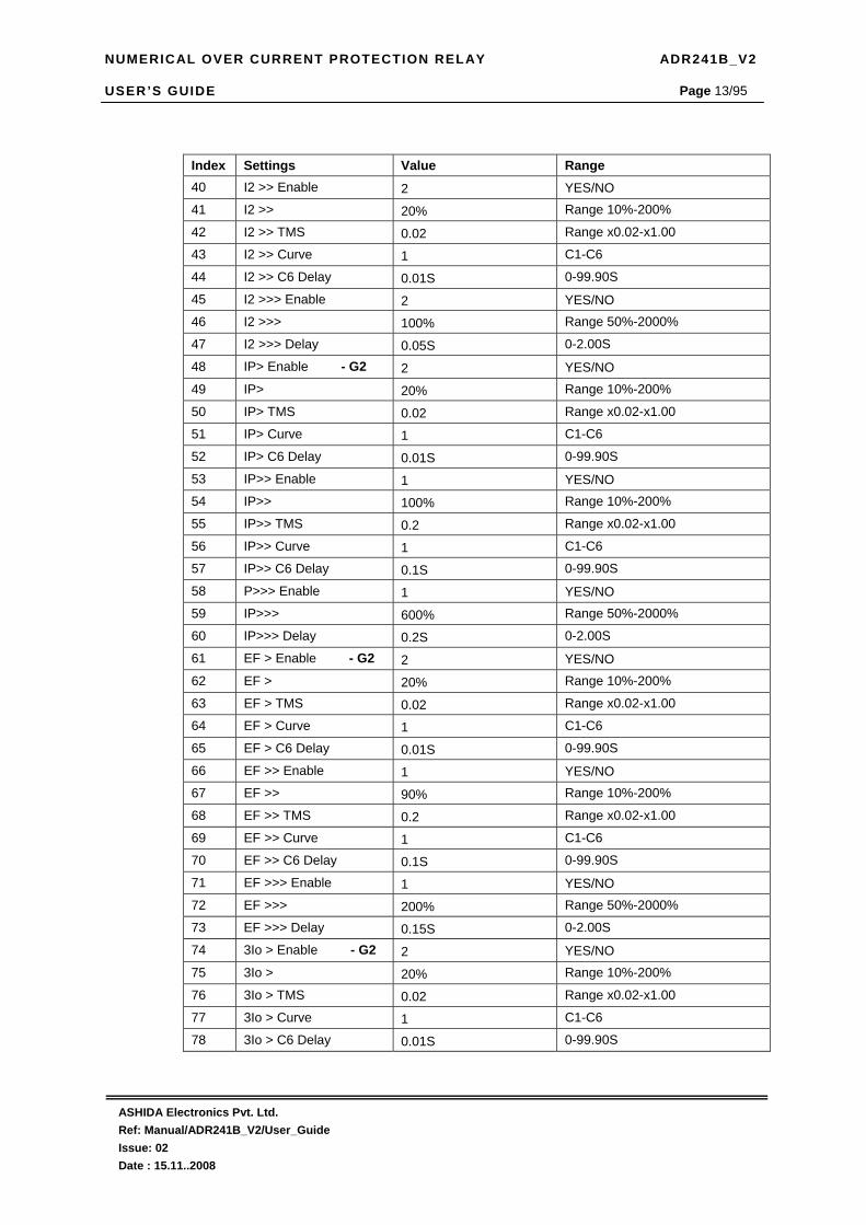
Page 13/95
Index Settings Value Range 40 I2 >> Enable 2 YES/NO 41 I2 >> 20% Range 10%-200%
42 I2 >> TMS 0.02 Range x0.02-x1.00
43 I2 >> Curve 1 C1-C6
44 I2 >> C6 Delay 0.01S 0-99.90S
45 I2 >>> Enable 2 YES/NO 46 I2 >>> 100% Range 50%-2000%
47 I2 >>> Delay 0.05S 0-2.00S
48 IP> Enable - G2 2 YES/NO
49 IP> 20% Range 10%-200%
50 IP> TMS 0.02 Range x0.02-x1.00
51 IP> Curve 1 C1-C6
52 IP> C6 Delay 0.01S 0-99.90S
53 IP>> Enable 1 YES/NO 54 IP>> 100% Range 10%-200%
55 IP>> TMS 0.2 Range x0.02-x1.00
56 IP>> Curve 1 C1-C6
57 IP>> C6 Delay 0.1S 0-99.90S
58 P>>> Enable 1 YES/NO 59 IP>>> 600% Range 50%-2000%
60 IP>>> Delay 0.2S 0-2.00S
61 EF > Enable - G2 2 YES/NO
62 EF > 20% Range 10%-200%
63 EF > TMS 0.02 Range x0.02-x1.00
64 EF > Curve 1 C1-C6
65 EF > C6 Delay 0.01S 0-99.90S
66 EF >> Enable 1 YES/NO 67 EF >> 90% Range 10%-200%
68 EF >> TMS 0.2 Range x0.02-x1.00
69 EF >> Curve 1 C1-C6
70 EF >> C6 Delay 0.1S 0-99.90S
71 EF >>> Enable 1 YES/NO 72 EF >>> 200% Range 50%-2000%
73 EF >>> Delay 0.15S 0-2.00S
74 3Io > Enable - G2 2 YES/NO
75 3Io > 20% Range 10%-200%
76 3Io > TMS 0.02 Range x0.02-x1.00
77 3Io > Curve 1 C1-C6
78 3Io > C6 Delay 0.01S 0-99.90S

NUMERICAL OVER CURRENT PROTECTION RELAY ADR241B_V2 USER’S GUIDE
ASHIDA Electronics Pvt. Ltd. Ref: Manual/ADR241B_V2/User_Guide Issue: 02 Date : 15.11..2008
Page 14/95
79 3Io >> Enable 2 YES/NO 80 3Io >> 20% Range 10%-200%
81 3Io >> TMS 0.02 Range x0.02-x1.00
82 3Io >> Curve 1 C1-C6
83 3Io >> C6 Delay 0.01S 0-99.90S
84 3Io >>> Enable 2 YES/NO 85 3Io >>> 100% Range 50%-2000%
86 3Io >>> Delay 0.05S 0-2.00S
87 I2 >> Enable - G2 2 YES/NO 88 I2 >> 20% Range 10%-200%
89 I2 >> TMS 0.02 Range x0.02-x1.00
90 I2 >> Curve 1 C1-C6
91 I2 >> C6 Delay 0.01S 0-99.90S
92 I2 >>> Enable 2 YES/NO 93 I2 >>> 100% Range 50%-2000%
94 I2 >>> Delay 0.05S 0-2.00S
95 ARR Enable 1 YES/NO 99 N SHOT 2 Range 00-04 97 DT1 40S Range 0.10-180.00S 98 DT2 60S Range 0.10-180.00S 99 DT3 1S Range 0.10-180.00S 100 DT4 1S Range 0.10-180.00S 101 Reclaim Time 30S Range 1.0-200.0S

NUMERICAL OVER CURRENT PROTECTION RELAY ADR241B_V2 USER’S GUIDE
ASHIDA Electronics Pvt. Ltd. Ref: Manual/ADR241B_V2/User_Guide Issue: 02 Date : 15.11..2008
Page 15/95
4.4. MENUS
4.4.1. Default Display : After Power ON or when the HW RESET + LED RESET push button is pressed simultaneously, the relay will display the following message.
Ashida Numerical 3OC/1EF IDMT Relay ADR241B_V2_R2 V02.08 Unit ID = 0001
This window will flash momentarily showing the following Relay Name : 3OC/1EF IDMT Relay Relay Type : ADR241B_V2_R2 Software Version : V02.01 Unit ID = 0001 Then the control will go automatically to default window
Secondary Current R = 000.01 Y = 000.01 B = 000.02 3Io = 000.02 CT Sec. Selected = 1A
This is default window showing the actual Secondary Load Current as per “CT Sec” selection Press the arrow key ( ) the relay will display Main menu directly as follows.

NUMERICAL OVER CURRENT PROTECTION RELAY ADR241B_V2 USER’S GUIDE
ASHIDA Electronics Pvt. Ltd. Ref: Manual/ADR241B_V2/User_Guide Issue: 02 Date : 15.11..2008
Page 16/95
4.4.2. Main Menu List
→ Measurement ← General Settings OC– G1 Settings EF– G1 Settings 3Io– G1 Settings NPS– G1 Settings OC– G2 Settings EF– G2 Settings 3Io– G2 Settings NPS–G2 Settings ARR Settings Relay/LED Config Fault 1 Fault 2 Fault 3 Fault 4 Fault 5 Fault 6 Fault 7 Fault 8 Fault 9 Fault 10 Fault 11 Fault 12 Fault 13 Fault 14 Fault 15 Fault 16 Fault 17 Fault 18 Fault 19 Fault 20 Status Error Log
Close Trip Active Group G2
Date/Time
Measurement, General Settings, OC–G1 Settings, EF–G1 Settings, 3Io–G1 Settings, NPS–G1 Settings, OC–G2 Settings, EF–G2 Settings, 3Io–G2 Settings, NPS–G2 Settings ARR Settings, Relay/LED Config, Fault 1, Fault 2, Fault 3, Fault 4, Fault 5, Fault 6, Fault 7, Fault 8, Fault 9, Fault 10, Status, , Fault 11, Fault 12, Fault 13, Fault 14, Fault 15, Fault 16, Fault 17, Fault 18, Fault 19, Fault 20, Status, Error Log, Close, Trip, Active Group G1 and Date/Time, these are the Main Menus available in this relay. Since the LCD Display consist only of 4 Lines, the main menu list can be scrolled up or down by using the Up Arrow key ( ) or the Down Arrow key ( ). The arrow pointers suggest that particular main menu is selected.
Secondary Current R = 000.00 Y = 000.00 B = 000.00 3Io = 000.02 CT Sec. Selected = 1A
This is default window showing the actual Secondary Load Current as per “CT Sec” selection Press the arrow key ( ) the relay will display Main menu directly as follows.

NUMERICAL OVER CURRENT PROTECTION RELAY ADR241B_V2 USER’S GUIDE
ASHIDA Electronics Pvt. Ltd. Ref: Manual/ADR241B_V2/User_Guide Issue: 02 Date : 15.11..2008
Page 17/95
4.4.2.1. Main Menu List Details
→ Measurement ←
This menu is to view the actual load current in primary as well as secondary as per the CT Secondary and CT Primary selection for all protection function. Press the arrow key ( ) the relay will display as follow.
→ General Settings ←
Password protected window for “General Setting’’ for setting New Password, Language Selection , Unit ID, Baud Rate, Com Port, Set Parity, BF Enable, BF Delay, BF Cont,. CT Sec., C.T. EF, CT Primary, Local Control, Trip Circuit, Trip Cont., Active Group, Cold Load Pick-up and EF Current Press the arrow key ( ) the relay will display as follow.
→ OC- G1 Settings ←
Password protected window for “OC Settings’’ for setting IP> Enable, Ip>% Range, IP>TMS, IP> Curve, IP>C6 Delay, IP>> Enable, Ip>> % Range, IP>>TMS, IP>> Curve, IP>>C6 Delay, IP>>> Enable, Ip>>>% Range, IP>>> C6 Delay. Press the arrow key ( ) the relay will display as follow.
→ NPS – G1 Settings ←
Password protected window for “NPS Setting’’ for setting I2>> Enable, I2>>% Range, I2>>TMS, I2>>Curve, I2>>C6 Delay, I2>>> Enable, I2>>>% Range, I2>>>Delay Press the arrow key ( ) the relay will display as follow.
→ EF – G1 Settings ←
Password protected window for “EF Settings’’ for setting IE> Enable, IE>% Range, IE>TMS, IE> Curve, IE>C6 Delay, IE>> Enable, IE>>% Range, IE>>TMS, IE>> Curve, IE>>C6 Delay, IE>>> Enable, IE>>> % Range and IE>>> C6 Delay Press the arrow key ( ) the relay will display as follow.
→ 3Io – G1 Settings ←
Password protected window for “3Io Settings’’ for setting 3Io> Enable, 3Io>% Range, 3Io>TMS, 3Io> Curve, 3Io>C6 Delay, 3Io>> Enable, 3Io>>% Range, 3Io>>TMS, 3Io>> Curve, 3Io>>C6 Delay, 3Io>>> Enable, 3Io>>> Range, 3Io>>> C6 Delay Press the arrow key ( ) the relay will display as follow.
→ OC- G2 Settings ←
Password protected window for “OC Settings’’ for setting IP> Enable, Ip>% Range, IP>TMS, IP> Curve, IP>C6 Delay, IP>> Enable, Ip>> %Range, IP>>TMS, IP>> Curve, IP>>C6 Delay, IP>>> Enable, Ip>>>% Range, IP>>> C6 Delay. Press the arrow key ( ) the relay will display as follow.

NUMERICAL OVER CURRENT PROTECTION RELAY ADR241B_V2 USER’S GUIDE
ASHIDA Electronics Pvt. Ltd. Ref: Manual/ADR241B_V2/User_Guide Issue: 02 Date : 15.11..2008
Page 18/95
→ Relay/LED Config ←
Password protected window for “Relay LED Config’’ for setting RL1, RL1 Cont, RL2, RL2 Cont, RL3, RL3 Cont, RL4, RL4 Cont, RL5, RL5 Cont, L5 Green, L5 Green, L5 Red, L5 Red, L6 Green, L6 Green, L6 Red, L6 Red, L7 Green, L7 Green, L7 Red , L7 Red, S1, S2, S3, S4 & S5 Press the arrow key ( ) the relay will display as follow.
→ Fault 1 ←
This menu is to view the latest fault data stored by the relay. That is Trip Flag, Trip Counter (TC), Secondary current, Date Time and Primary current. Press the arrow key ( ) the relay will display as follow.
→ Fault 2 ←
This menu is to view the first latest fault data stored by the relay. That is Trip Flag, Trip Counter (TC), Secondary current, Date Time and Primary current. Press the arrow key ( ) the relay will display as follow.
→ ARR Settings ←
Password protected window for “ARR Setting’’ for setting N SHOT, DT1, DT2, DT3, DT4 and Reclaim Time selection. Press the arrow key ( ) the relay will display as follow.
→ EF – G2 Settings ←
Password protected window for “EF Settings’’ for setting IE> Enable, IE>% Range, IE>TMS, IE> Curve, IE>C6 Delay, IE>> Enable, IE>>% Range, IE>>TMS, IE>> Curve, IE>>C6 Delay, IE>>> Enable, IE>>> % Range and IE>>> C6 Delay Press the arrow key ( ) the relay will display as follow.
→ NPS – G2 Settings ←
Password protected window for “NPS Setting’’ for setting I2>> Enable, I2>>% Range, I2>>TMS, I2>>Curve, I2>>C6 Delay, I2>>> Enable, I2>>>% Range, I2>>>Delay Press the arrow key ( ) the relay will display as follow.
→ 3Io – G2 Settings ←
Password protected window for “3Io Settings’’ for setting 3Io> Enable, 3Io>% Range, 3Io>TMS, 3Io> Curve, 3Io>C6 Delay, 3Io>> Enable, 3Io>>% Range, 3Io>>TMS, 3Io>> Curve, 3Io>>C6 Delay, 3Io>>> Enable, 3Io>>> Range, 3Io>>> C6 Delay Press the arrow key ( ) the relay will display as follow.

NUMERICAL OVER CURRENT PROTECTION RELAY ADR241B_V2 USER’S GUIDE
ASHIDA Electronics Pvt. Ltd. Ref: Manual/ADR241B_V2/User_Guide Issue: 02 Date : 15.11..2008
Page 19/95
→ Fault 3 ←
This menu is to view the second latest fault data stored by the relay. That is Trip Flag, Trip Counter (TC), Secondary current, Date Time and Primary current. Press the arrow key ( ) the relay will display as follow.
→ Fault 4 ←
This menu is to view the third latest fault data stored by the relay. That is Trip Flag, Trip Counter (TC), Secondary current, Date Time and Primary current. Press the arrow key ( ) the relay will display as follow.
→ Fault 5 ←
This menu is to view the fourth latest fault data stored by the relay. That is Trip Flag, Trip Counter (TC), Secondary current, Date Time and Primary current. Press the arrow key ( ) the relay will display as follow.
→ Fault 6 ←
This menu is to view the fifth latest fault data stored by the relay. That is Trip Flag, Trip Counter (TC), Secondary current, Date Time and Primary current. Press the arrow key ( ) the relay will display as follow.
→ Fault 7 ←
This menu is to view the sixth latest fault data stored by the relay. That is Trip Flag, Trip Counter (TC), Secondary current, Date Time and Primary current. Press the arrow key ( ) the relay will display as follow.
→ Fault 8 ←
This menu is to view the seventh latest fault data stored by the relay. That is Trip Flag, Trip Counter (TC), Secondary current, Date Time and Primary current. Press the arrow key ( ) the relay will display as follow.
→ Fault 9 ←
This menu is to view the eight latest fault data stored by the relay. That is Trip Flag, Trip Counter (TC), Secondary current, Date Time and Primary current. Press the arrow key ( ) the relay will display as follow.

NUMERICAL OVER CURRENT PROTECTION RELAY ADR241B_V2 USER’S GUIDE
ASHIDA Electronics Pvt. Ltd. Ref: Manual/ADR241B_V2/User_Guide Issue: 02 Date : 15.11..2008
Page 20/95
→ Fault 10 ←
This menu is to view the ninth latest fault data stored by the relay. That is Trip Flag, Trip Counter (TC), Secondary current, Date Time and Primary current. Press the arrow key ( ) the relay will display as follow.
→ Fault 11 ←
This menu is to view the tenth latest fault data stored by the relay. That is Trip Flag, Trip Counter (TC), Secondary current, Date Time and Primary current. Press the arrow key ( ) the relay will display as follow.
→ Fault 12 ←
This menu is to view the eleventh latest fault data stored by the relay. That is Trip Flag, Trip Counter (TC), Secondary current, Date Time and Primary current. Press the arrow key ( ) the relay will display as follow.
→ Fault 13 ←
This menu is to view the twelfth latest fault data stored by the relay. That is Trip Flag, Trip Counter (TC), Secondary current, Date Time and Primary current. Press the arrow key ( ) the relay will display as follow.
→ Fault 14 ←
This menu is to view the thirteenth latest fault data stored by the relay. That is Trip Flag, Trip Counter (TC), Secondary current, Date Time and Primary current. Press the arrow key ( ) the relay will display as follow.
→ Fault 15 ←
This menu is to view the fourteenth latest fault data stored by the relay. That is Trip Flag, Trip Counter (TC), Secondary current, Date Time and Primary current. Press the arrow key ( ) the relay will display as follow.
→ Fault 16 ←
This menu is to view the fifthteenth latest fault data stored by the relay. That is Trip Flag, Trip Counter (TC), Secondary current, Date Time and Primary current. Press the arrow key ( ) the relay will display as follow.
NUMERICAL OVER CURRENT PROTECTION RELAY ADR241B_V2 USER’S GUIDE
ASHIDA Electronics Pvt. Ltd. Ref: Manual/ADR241B_V2/User_Guide Issue: 02 Date : 15.11..2008
Page 21/95
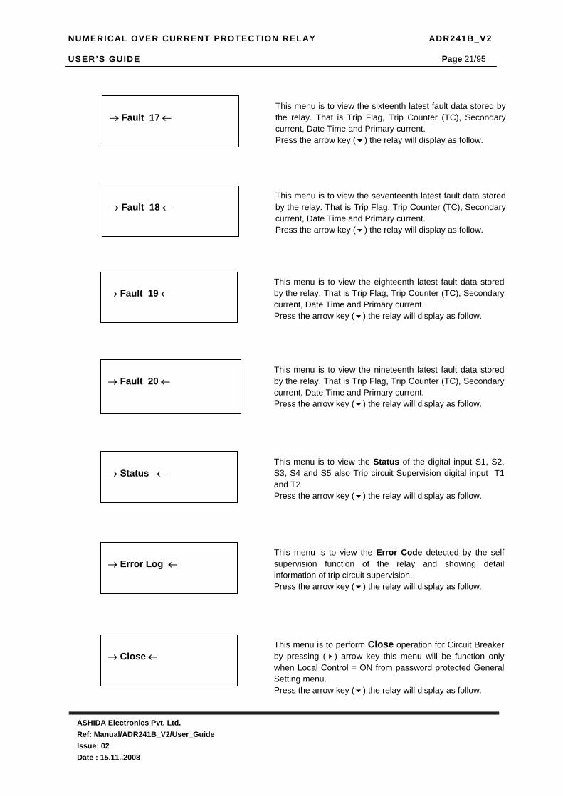
→ Status ←
This menu is to view the Status of the digital input S1, S2, S3, S4 and S5 also Trip circuit Supervision digital input T1 and T2 Press the arrow key ( ) the relay will display as follow.
→ Error Log ←
This menu is to view the Error Code detected by the self supervision function of the relay and showing detail information of trip circuit supervision. Press the arrow key ( ) the relay will display as follow.
→ Fault 17 ←
This menu is to view the sixteenth latest fault data stored by the relay. That is Trip Flag, Trip Counter (TC), Secondary current, Date Time and Primary current. Press the arrow key ( ) the relay will display as follow.
→ Fault 18 ←
This menu is to view the seventeenth latest fault data stored by the relay. That is Trip Flag, Trip Counter (TC), Secondary current, Date Time and Primary current. Press the arrow key ( ) the relay will display as follow.
→ Fault 19 ←
This menu is to view the eighteenth latest fault data stored by the relay. That is Trip Flag, Trip Counter (TC), Secondary current, Date Time and Primary current. Press the arrow key ( ) the relay will display as follow.
→ Fault 20 ←
This menu is to view the nineteenth latest fault data stored by the relay. That is Trip Flag, Trip Counter (TC), Secondary current, Date Time and Primary current. Press the arrow key ( ) the relay will display as follow.
→ Close ←
This menu is to perform Close operation for Circuit Breaker by pressing ( ) arrow key this menu will be function only when Local Control = ON from password protected General Setting menu. Press the arrow key ( ) the relay will display as follow.

NUMERICAL OVER CURRENT PROTECTION RELAY ADR241B_V2 USER’S GUIDE
ASHIDA Electronics Pvt. Ltd. Ref: Manual/ADR241B_V2/User_Guide Issue: 02 Date : 15.11..2008
Page 22/95
→ Date Time ←
Password protected window for setting “Date Time’’ Press the arrow key ( ) the relay will display as follow.
→ Measurement ←
→ Trip ←
This menu is to perform Trip operation for Circuit Breaker by pressing ( ) arrow key this menu will be function only when Local Control = ON from password protected General Setting menu. Press the arrow key ( ) the relay will display as follow
→ Active Group G1 ←
This menu will show selected Active Group from password protected menu General Setting. Press the arrow key ( ) the relay will display as follow

NUMERICAL OVER CURRENT PROTECTION RELAY ADR241B_V2 USER’S GUIDE
ASHIDA Electronics Pvt. Ltd. Ref: Manual/ADR241B_V2/User_Guide Issue: 02 Date : 15.11..2008
Page 23/95
4.4.3. MEASUREMENT
4.4.3.1. To View – Measurement
→ Measurement ←
This menu is to view the actual load current in primary as well as secondary as per the CT Secondary and CT Primary selection. Press the arrow key ( ) the relay will display as follow.
Secondary Current R = 000.00 Y = 000.00 B = 000.00 3Io =000.03 CT Sec. Selected = 1A
This window will show actual Secondary Current as per “CT Sec.‘’ selection Press the arrow key ( ) the relay will display as follows.
Primary Current R = 00000A Y = 00000A B = 00000A 3Io = 00000A
This window will show actual Primary Current as per “CT Primary.‘’ selection, it will display current in K (KAmp) . When “CT Primary ≥500? “ Press the arrow key ( ) the relay will display as follows.
→ Measurement ←
I1=000.01 I2=000.01 EF=000.01
This window will show actual Secondary Current as per respective C.T. Secondary setting. Positive phase sequence Current – I1 Negative phase Sequence Current –I2 Exta EF current (from external CBCT) - Ie Press the arrow key ( ) to display the main menu.

NUMERICAL OVER CURRENT PROTECTION RELAY ADR241B_V2 USER’S GUIDE
ASHIDA Electronics Pvt. Ltd. Ref: Manual/ADR241B_V2/User_Guide Issue: 02 Date : 15.11..2008
Page 24/95
4.4.4. GENERAL SETTINGS
4.4.4.1. To Set – General Setting
→ General Setting ←
Password protected window for “General Setting’’ for setting New Password, Language Selection , Unit ID, Baud Rate, Com Port, Set Parity, BF Enable, BF Delay, BF Cont,. CT Sec., C.T. EF, CT Primary, Local Control, Trip Circuit, Trip Cont., Active Group, Cold Load Pick-up and EF Current Press the arrow key ( ) the relay will display as follow.
Password = 001 Use Inr/Dec
Enter the previously set password, By using the up arrow key or the down arrow key ( ). Note : Default password setting is ‘000’ Press the arrow key ( ) the relay will display as follow.
General Settings Unit ID = 001 Range 001-250 Use Inr/Dec
By using the up arrow key ( ) or the down arrow key ( ) the desired Unit ID address can be selected. The unit address can be set from 001 to 250 in steps of 001, which means total 250 devises can be connected to single computer. The 250th address is reserved for special command. These settings are required to communicate with the SCADA computer. Press the arrow key ( ) the relay will display as follow.
General Settings Baud Rate = 09600 Range 1200-57600 Use Inr/Dec
By using the up arrow key ( ) or the down arrow key ( ) the desired Baud Rate can be set. The range is from 1200-57600. (i.e. 1200, 2400, 9600, 19200, 38400 and 57600) Press the arrow key ( ) the relay will display as follow.
General Settings New Password = 000 Range 000-099 Use Inr/Dec
By using the up arrow key ( ) or the down arrow key ( ) New Password can be set. The range is from 000-099 in steps of 001. Press the arrow key ( ) the relay will display as follow.
General Settings Language Sel. = ENG Range ENG / TUR Use Inr/Dec
By using the up arrow key ( ) or the down arrow key ( ) Language English / Turkey can be selected. Press the arrow key ( ) the relay will display as follow.
NUMERICAL OVER CURRENT PROTECTION RELAY ADR241B_V2 USER’S GUIDE
ASHIDA Electronics Pvt. Ltd. Ref: Manual/ADR241B_V2/User_Guide Issue: 02 Date : 15.11..2008
Page 25/95
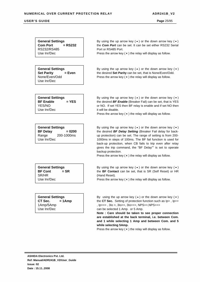
General Settings BF Delay = 0200 Range 200-1000ms Use Inr/Dec
By using the up arrow key ( ) or the down arrow key ( ) the desired BF Delay Setting (Breaker Fail delay for back-up protection) can be set. The range of setting is from 200-1000ms in steps of 100ms. The BF fail function is used for back-up protection, when CB fails to trip even after relay gives the trip command, the ”BF Delay”” is set to operate backup protection. Press the arrow key ( ) the relay will display as follow.
General Settings BF Enable = YES YES/NO Use Inr/Dec
By using the up arrow key ( ) or the down arrow key ( ) the desired BF Enable (Breaker Fail) can be set, that is YES or NO. If set YES then BF relay is enable and if set NO then it will be disable. Press the arrow key ( ) the relay will display as follow.
General Settings CT Sec. = 1Amp 1Amp/5Amp Use Inr/Dec
By using the up arrow key ( ) or the down arrow key ( ) the CT Sec. Setting of protection function such as Ip> , Ip>> , Ip>>> , 3Io >, 3Io>>, 3Io>>>, NPS>>,NPS>>> can be selected 1 Amp. or 5 Amp. Note : Care should be taken to see proper connection are established at the back terminal, i.e. between Com. and 1 while selecting 1 Amp and between Com. and 5 while selecting 5Amp. Press the arrow key ( ) the relay will display as follow.
General Settings Com Port = RS232 RS232/RS485 Use Inr/Dec
By using the up arrow key ( ) or the down arrow key ( ) the Com Port can be set. It can be set either RS232 Serial Port or RS485 Port. Press the arrow key ( ) the relay will display as follow.
General Settings Set Parity = Even None/Even/Odd Use Inr/Dec
By using the up arrow key ( ) or the down arrow key ( ) the desired Set Parity can be set, that is None/Even/Odd. Press the arrow key ( ) the relay will display as follow.
General Settings BF Cont = SR SR/HR Use Inr/Dec
By using the up arrow key ( ) or the down arrow key ( ) the BF Contact can be set, that is SR (Self Reset) or HR (Hand Reset). Press the arrow key ( ) the relay will display as follow.

NUMERICAL OVER CURRENT PROTECTION RELAY ADR241B_V2 USER’S GUIDE
ASHIDA Electronics Pvt. Ltd. Ref: Manual/ADR241B_V2/User_Guide Issue: 02 Date : 15.11..2008
Page 26/95
General Settings CT Primary = 0100 Range 10-2000 Use Inr/Dec
By using the up arrow key ( ) or the down arrow key ( ) the CT Primary setting can be applicable for protection function such as Ip> , Ip>> , Ip>>> , 3Io >, 3Io>>, 3Io>>>, NPS>>,NPS>>>. The range for CT Primary setting is form 10 to 2000 in steps of 1. Press the arrow key ( ) the relay will display as follow.
General Settings Local Control = YES YES / NO Use Inr/Dec
By using the up arrow key ( ) or the down arrow key ( ) Local Control selection can be enable TRIP push button function from relays front plate. Press the arrow key ( ) the relay will display as follow.
General Settings Trip Ckt = NO YES/NO Use Inr/Dec
By using the up arrow key ( ) or the down arrow key ( ) Trip Circuit Supervision function can be Enable / Disable that is YES or NO. If set YES then the Trip Circuit Supervision function will be Enable, if it is set as NO then Trip Circuit Supervision function will be Disable Press the arrow key ( ) the relay will display as follow.
General Settings Trip Cont = SR SR/HR Use Inr/Dec
By using the up arrow key ( ) or the down arrow key ( ) the Trip Contact can be set, that is SR (Self Reset) or HR (Hand Reset). Press the arrow key ( ) the relay will display as follow.
General Settings CT Sec. EF = 1 Amp 1Amp/5Amp Use Inr/Dec
By using the up arrow key ( ) or the down arrow key ( ) the CT Sec. Setting of protection function such as IE>, IE>>, IE>>> can be selected 1 Amp. or 5 Amp. Note : Care should be taken to see proper connection are established at the back terminal, i.e. between Com. and 1 while selecting 1 Amp and between Com. and 5 while selecting 5Amp. Press the arrow key ( ) the relay will display as follow.
General Settings Active Group = G1 G1 / G2 Use Inr/Dec
By using the up arrow key ( ) or the down arrow key ( ) Active Group can be selected. Press the arrow key ( ) the relay will display as follow.

NUMERICAL OVER CURRENT PROTECTION RELAY ADR241B_V2 USER’S GUIDE
ASHIDA Electronics Pvt. Ltd. Ref: Manual/ADR241B_V2/User_Guide Issue: 02 Date : 15.11..2008
Page 27/95
Save Settings Mode for Save
To Save any changes. Press the arrow key ( ) the relay will save the change and the following message is display. Note : If changes made are not to be saved press LED Reset or leave key pad untouched for 100 sec.
OK
This window will flash for moment The control will return to the main menu
→ General Setting ←
General Settings Cold Ld. PKP = NO YES / NO Use Inr/Dec
By using the up arrow key ( ) or the down arrow key ( ) the Cold Load Pick-up function can be Enable / Disable, That is YES for Enable and NO for Disable. Press the arrow key ( ) the relay will display as follow.

NUMERICAL OVER CURRENT PROTECTION RELAY ADR241B_V2 USER’S GUIDE
ASHIDA Electronics Pvt. Ltd. Ref: Manual/ADR241B_V2/User_Guide Issue: 02 Date : 15.11..2008
Page 28/95
4.4.4.2. To View – General Setting
→ General Setting ←
Press the arrow key ( ) the relay will display as follow.
→ General Setting ←
Language Sel. = ENG Unit ID = 0001 Baud Rate = 09600 Com Port = RS232
This window will show General Setting done previously. Press the arrow key ( ) the relay will display as follow. This is Page 1
Set Parity = Even BF Enable = YES BF Delay = 0200 BF Cont = SR
This window will show General Setting done previously. Press the arrow key ( ) the relay will display as follow. This is Page 2
CT Sec. = 1Amp CT Sec. EF = 1Amp CT Primary = 0100 Local Control = YES
This window will show General Setting done previously. Press the arrow key ( ) the relay will display the main menu. This is Page 3
Trip Ckt = NO Trip Cont. = SR Active Group = G1 Cold Ld PKP = NO
This window will show General Setting done previously. Press the arrow key ( ) the relay will display the main menu. This is Page 3

NUMERICAL OVER CURRENT PROTECTION RELAY ADR241B_V2 USER’S GUIDE
ASHIDA Electronics Pvt. Ltd. Ref: Manual/ADR241B_V2/User_Guide Issue: 02 Date : 15.11..2008
Page 29/95
4.4.5. OVER CURRENT (OC- G1) SETTINGS
4.4.5.1. To Set :- OC – G1 Setting
→ OC- G1 Setting ←
Password protected window for “OC-G1 Setting’’ for setting Password, IP> Stage1 Enable, IP> %Trip Setting, IP> TMS, IP> Curve selection, IP>C6 Delay, IP>> Stage 2 Enable, IP>> Trip Setting Stage 2, IP>> TMS, IP>> Curve selection, IP>>C6 Delay, IP>>> Stage 3 Enable, IP>>> Instantaneous Element Trip Setting, IP>>> Delay, Press the arrow key ( ) the relay will display as follow.
Password = 001 Use Inr/Dec
Enter the previously set password, By using the up arrow key or the down arrow key ( ). Note : Default password setting is ‘000’ Press the arrow key ( ) the relay will display as follow.
OC- G1 Settings IP> Enable = YES YES/NO Use Inr/Dec
By using the up arrow key ( ) or the down arrow key ( ) the desired IP> Enable (IDMT/DMT Trip setting stage 1) can be Enable / Disable that is YES / NO respectively. If set YES then IP> is enabled and if set NO then it will be disabled. Press the arrow key ( ) the relay will display as follow.
OC- G1 Settings IP> = 0020 Range 10%-200% Use Inr/Dec
By using the up arrow key ( ) or the down arrow key ( ) the desired IP> (IDMT/DMT Trip setting stage 1) can be set. The range is 10% to 200% in steps of 1%. Press the arrow key ( ) the relay will display as follow.
OC- G1 Settings IP> TMS = 01.00 Range x0.02-x1.00 Use Inr/Dec
By using the up arrow key ( ) or the down arrow key ( ) the desired IP> TMS (IDMT Time Multiplier Setting stage1 can be set. The range is from x0.02 to x1.00 in steps of 0.01 Note: If C6 DMT Curve is selected then ignore this setting Press the arrow key ( ) the relay will display as follow.
OC- G1 Settings IP> Curve = 0001 Range C1-C6 Use Inr/Dec
By using the up arrow key ( ) or the down arrow key ( ) the desired IP> Curve (IDMT/DMT Curve selection stage 1 can be set. Six different types of curves are provided C1 to C6. When the given value is 0001 Curve 1 is selected and when the given value 0002 Curve 2 is selected. In similar manner any desired curve can be selected as 0001 to 0006 correspond respectively with C1 to C6. Press the arrow key ( ) the relay will display as follow.

NUMERICAL OVER CURRENT PROTECTION RELAY ADR241B_V2 USER’S GUIDE
ASHIDA Electronics Pvt. Ltd. Ref: Manual/ADR241B_V2/User_Guide Issue: 02 Date : 15.11..2008
Page 30/95
Curve Description
C1 Normal Inverse 1 (10 Times 3.0 sec) C2 Normal Inverse 2 (10 Times 1.3 sec) C3 Very Inverse (10 Times 1.5 sec) C4 Extremely Inverse (10 Times 0.8 sec) C5 Long Time Inverse (10 Times 13.3 sec) C6 Definite Time (Inst. to 99.9 sec)
OC- G1 Settings IP> C6 Delay = 00.05 Range 00.00 - 99.90S Use Inr/Dec
By using the up arrow key ( ) or the down arrow key ( ) the desired IP> C6 Delay (DMT Definite Time selection stage 1) can be set. The setting range for of IP> C6 delay is from 00.00 (Inst) to 99.9secs in steps of 0.05 sec. Note: If C1 to C5 curve is selected then ignore this setting for IP> . Press the arrow key ( ) the relay will display as follow.
OC- G1 Settings IP>> Enable = YES YES/NO Use Inr/Dec
By using the up arrow key ( ) or the down arrow key ( ) the desired IP>> Enable (IDMT/DMT Trip setting stage 2) can be set, that is YES or NO. If set YES then IP>> is enabled and if set NO then it will be disabled. Press the arrow key ( ) the relay will display as follow.
OC- G1 Settings IP>> = 0020 Range 10%-200% Use Inr/Dec
By using the up arrow key ( ) or the down arrow key ( ) the desired IP>> (IDMT/DMT Trip setting stage 2) can be set. The range is 10% to 200% in steps of 1%. Press the arrow key ( ) the relay will display as follow.
OC- G1 Settings IP>> TMS = 01.00 Range x0.02-x1.00 Use Inr/Dec
By using the up arrow key ( ) or the down arrow key ( ) the desired IP>> TMS (IDMT Time multiply setting stage 2) can be set. The range is from x0.02 to x1.00 in steps of 0.01 Note: If C6 DMT Curve is selected then ignore this setting Press the arrow key ( ) the relay will display as follow.
OC- G1 Settings IP>> Curve = 0001 Range C1-C6 Use Inr/Dec
By using the up arrow key ( ) or the down arrow key ( ) the desired IP>> Curve (IDMT/DMT Curve selection stage 2) can be set. Six different types of curves are provided C1 to C6. When the given value is 0001 Curve 1 is selected and when the given value 0002 Curve 2 is selected. In similar manner any desired curve can be selected as 0001 to 0006 correspond respectively with C1 to C6. Press the arrow key ( ) the relay will display as follow.

NUMERICAL OVER CURRENT PROTECTION RELAY ADR241B_V2 USER’S GUIDE
ASHIDA Electronics Pvt. Ltd. Ref: Manual/ADR241B_V2/User_Guide Issue: 02 Date : 15.11..2008
Page 31/95
Curve Description
C1 Normal Inverse 1 (10 Times 3.0 sec) C2 Normal Inverse 2 (10 Times 1.3 sec) C3 Very Inverse (10 Times 1.5 sec) C4 Extremely Inverse (10 Times 0.8 sec) C5 Long Time Inverse (10 Times 13.3 sec) C6 Definite Time (Inst. to 99.9 sec)
OC- G1 Settings IP>>> Enable = YES YES/NO Use Inr/Dec
By using the up arrow key ( ) or the down arrow key ( ) the desired IP>>> Enable (Instantaneous Trip Setting Stage 3) can be set, that is YES or NO. If set YES then IP>>> is enabled and if set NO then it will be disabled Press the arrow key ( ) the relay will display as follow.
OC- G1 Settings IP>>> = 0200 Range 50%- 2000% Use Inr/Dec
By using the up arrow key ( ) or the down arrow key ( ) the desired IP>>> (Instantaneous Trip Setting Stage 3 can be set. The range is 50% to 2000% in steps of 50%. Press the arrow key ( ) the relay will display as follow.
OC- G1 Settings IP>> C6 Delay = 000.1 Range 00.00-99.9S Use Inr/Dec
By using the up arrow key ( ) or the down arrow key ( ) the desired IP>> C6 Delay (DMT Definite Time selection stage 2) can be set. The setting range for of IP>> C6 delay is from 00.00(Inst) to 99.9secs in steps of 0.05 sec. Note: If C1 to C5 curve is selected then ignore this setting for IP>>. Press the arrow key ( ) the relay will display as follow.
Save Settings Mode for Save
To Save any changes. Press the arrow key ( ) the relay will save the change and the following message is display. Note : If changes made are not to be saved press LED Reset or leave key pad untouched for 100Sec.
OK
This window will flash for moment The control will return to the main menu
OC- G1 Settings IP>>> Delay = 00.05 Range 00.00-2.00S Use Inr/Dec
By using the up arrow key ( ) or the down arrow key ( ) the desired IP>>> Delay (DMT Definite Time selection stage 3) can be selected. The setting range for of IP>>> delay is from00.00 (Inst) to 2.00secs in steps of 0.05secs. Press the arrow key ( ) the relay will display as follow.

NUMERICAL OVER CURRENT PROTECTION RELAY ADR241B_V2 USER’S GUIDE
ASHIDA Electronics Pvt. Ltd. Ref: Manual/ADR241B_V2/User_Guide Issue: 02 Date : 15.11..2008
Page 32/95
4.4.5.2. To View :- OC- G1 Settings
→ OC- G1 Settings ←
→ OC- G1 Setting ←
Press the arrow key ( ) the relay will display as follow.
IP>=ON IP> = 0020 IP> TMS = 01.00 IP> Curve = 0001 IP> C6 Delay = 00.05
This window will show OC Setting done previously. Press the arrow key ( ) the relay will display as follow.
IP>>=ON IP>> = 0020 IP>>TMS = 01.00 IP>> Curve = 0001 IP>> C6 Delay = 00.05
This window will show OC Setting done previously. Press the arrow key ( ) the relay will display as follow.
IP>>>=ON IP>>> = 0200 IP>>>Delay = 00.05
This window will show OC Setting done previously. Press the arrow key ( ) the relay will display the main menu.
→ OC- G1 Setting ←

NUMERICAL OVER CURRENT PROTECTION RELAY ADR241B_V2 USER’S GUIDE
ASHIDA Electronics Pvt. Ltd. Ref: Manual/ADR241B_V2/User_Guide Issue: 02 Date : 15.11..2008
Page 33/95
4.4.6 EARTH FAULT (EF – G1) SETTINGS
4.4.6.1 To Set :– EF– G1 Setting:
EF – G1 Settings IE> Enable = YES YES/NO Use Inr/Dec
By using the up arrow key ( ) or the down arrow key ( ) the desired IE> Enable (IDMT/DMT Trip setting stage 1) can be set, that is YES or NO. If set YES then IE> is enabled and if set NO then it will be disabled. Press the arrow key ( ) the relay will display as follow.
EF – G1 Settings IE> = 0020 Range 10% - 200% Use Inr/Dec
By using the up arrow key ( ) or the down arrow key ( ) the desired IE> (IDMT/DMT Trip setting stage 1) can be set. The range is 10% to 200% in steps of 1%. Press the arrow key ( ) the relay will display as follow.
EF – G1 Settings IE> TMS = 01.00 Range x0.02-x1.00 Use Inr/Dec
By using the up arrow key ( ) or the down arrow key ( ) the desired IE> TMS (IDMT Time multiply setting stage 1) can be set. The range is from x0.02 to x1.00 in steps of 0.01 Note: If C6 DMT Curve is selected then ignore this setting Press the arrow key ( ) the relay will display as follow.
EF – G1 Settings IE> Curve = 0001 Range C1-C6 Use Inr/Dec
By using the up arrow key ( ) or the down arrow key ( ) the desired IE> Curve (IDMT/DMT Curve selection stage 1) can be set. Six different types of curves are provided C1 to C6. When the given value is 0001 Curve 1 is selected and when the given value 0002 Curve 2 is selected. In similar manner any desired curve can be selected as 0001 to 0006 correspond respectively with C1 to C6. Press the arrow key ( ) the relay will display as follow.
→ EF – G1 Setting ←
Password protected window “EF– G1 Setting’’ for setting Password, IE> Enable, IE> Trip Setting Stage 1, IE> TMS, IE> Curve Selection, IE>C6 Delay, IE>> Enable, IE>> Trip Setting Stage 2, IE>> TMS, IE>> Curve Selection, IE>>C6 Delay, IE>>> Enable, IE>>> Trip setting High Set, IE>>> Delay. Press the arrow key ( ) the relay will display as follow.
Password = 001 Use Inr/Dec
Enter the previously y set password, By using the up arrow key or the down arrow key ( ). Note : Default password setting is ’0000’ Press the arrow key ( ) the relay will display as follow.

NUMERICAL OVER CURRENT PROTECTION RELAY ADR241B_V2 USER’S GUIDE
ASHIDA Electronics Pvt. Ltd. Ref: Manual/ADR241B_V2/User_Guide Issue: 02 Date : 15.11..2008
Page 34/95
Curve Description
C1 Normal Inverse 1 (10 Times 3.0 sec) C2 Normal Inverse 2 (10 Times 1.3 sec) C3 Very Inverse (10 Times 1.5 sec) C4 Extremely Inverse (10 Times 0.8 sec) C5 Long Time Inverse (10 Times 13.3 sec) C6 Definite Time (Inst. to 99.9 sec)
EF – G1 Settings IE> C6 Delay = 00.05 Range 00.00-99.90S Use Inr/Dec
By using the up arrow key ( ) or the down arrow key ( ) the desired IE> C6 Delay (DMT Definite Time selection stage 1) can be set. The setting range for of IE> C6 delay is from 00.00 (Inst) to 99.90 secs in steps of 0.05 sec. Note: If C1 to C5 curve is selected then ignore this setting for IE>. Press the arrow key ( ) the relay will display as follow.
EF – G1 Settings IE>> Enable = YES YES/NO Use Inr/Dec
By using the up arrow key ( ) or the down arrow key ( ) the desired IE>> Enable (IDMT/DMT Trip setting stage 2) can be set, that is YES or NO. If set YES then IE>> is enabled and if set NO then it will be disabled. Press the arrow key ( ) the relay will display as follow.
EF – G1 Settings IE>> = 0020 Range 10% - 200% Use Inr/Dec
By using the up arrow key ( ) or the down arrow key ( ) the desired IE>> (IDMT/DMT Trip setting stage 2) can be set. The range is 10% to 200% in steps of 1%. Press the arrow key ( ) the relay will display as follow.
EF – G1 Settings IE>> TMS = 01.00 Range x0.02-x1.00 Use Inr/Dec
By using the up arrow key ( ) or the down arrow key ( ) the desired IE>> TMS (IDMT Time Multiplier Setting stage 2 can be set. The range is from x0.02 to x1.00 in steps of 0.01 Note: If C6 DMT Curve is selected then ignore this setting Press the arrow key ( ) the relay will display as follow.
EF – G1 Settings IE>> Curve = 0001 Range C1-C6 Use Inr/Dec
By using the up arrow key ( ) or the down arrow key ( ) the desired IE>> Curve (IDMT/DMT Curve selection stage 2 can be set. Six different types of curves are provided C1 to C6. When the given value is 0001 Curve 1 is selected and when the given value 0002 Curve 2 is selected. In similar manner any desired curve can be selected as 0001 to 0006 correspond respectively with C1 to C6. Press the arrow key ( ) the relay will display as follow.

NUMERICAL OVER CURRENT PROTECTION RELAY ADR241B_V2 USER’S GUIDE
ASHIDA Electronics Pvt. Ltd. Ref: Manual/ADR241B_V2/User_Guide Issue: 02 Date : 15.11..2008
Page 35/95
Curve Description
C1 Normal Inverse 1 (10 Times 3.0 sec) C2 Normal Inverse 2 (10 Times 1.3 sec) C3 Very Inverse (10 Times 1.5 sec) C4 Extremely Inverse (10 Times 0.8 sec) C5 Long Time Inverse (10 Times 13.3 sec) C6 Definite Time (Inst. to 99.9 sec)
Save Settings Mode for Save
To Save any changes. Press the arrow key ( ) the relay will save the change and the following message is display. Note : If changes made are not to be saved press LED Reset or leave key pad untouched for 100Sec.
OK
This window will flash for moment The control will return to the main menu
EF – G1 Settings IE>>> Enable = YES YES/NO Use Inr/Dec
By using the up arrow key ( ) or the down arrow key ( ) the desired IE>>> Enable (Instantaneous Trip Setting Stage 3) can be set, that is YES or NO. If set YES then IE>>> is enabled and if set NO then it will be disabled Press the arrow key ( ) the relay will display as follow.
EF – G1 Settings IE>>> = 0200 Range 50%- 2000% Use Inr/Dec
By using the up arrow key ( ) or the down arrow key ( ) the desired IE>>> (Instantaneous Trip Setting Stage 3) can be set. The range is 50% to 2000% in steps of 50%. Press the arrow key ( ) the relay will display as follow.
EF – G1 Settings IE>>> Delay = 00.05 Range 00.00 - 2.00S Use Inr/Dec
By using the up arrow key ( ) or the down arrow key ( ) the desired IE>>> Delay (DMT Definite Time selection stage 3) can be selected. The setting range for of IE>>> delay is from 00.00 (Inst) to 2.00 secs in steps of 0.05 secs. Press the arrow key ( ) the relay will display as follow.
EF – G1 Settings IE>> C6 Delay = 00.05 Range 00.00 - 99.9S Use Inr/Dec
By using the up arrow key ( ) or the down arrow key ( ) the desired IE>> C6 Delay (DMT Definite Time selection stage 2) can be set. The setting range for of IE>> C6 delay is from 00.00 (Inst) to 99.90 secs in steps of 0.05 sec. Note: If C1 to C5 curve is selected then ignore this setting for IE>>. Press the arrow key ( ) the relay will display as follow.

NUMERICAL OVER CURRENT PROTECTION RELAY ADR241B_V2 USER’S GUIDE
ASHIDA Electronics Pvt. Ltd. Ref: Manual/ADR241B_V2/User_Guide Issue: 02 Date : 15.11..2008
Page 36/95
4.4.6.2 To View :– EF– G1 Setting
→ EF – G1 Setting ←
→ EF – G1 Setting ←
Press the arrow key ( ) the relay will display as follow.
IE>=ON IE> = 0020 IE> TMS = 01.00 IE> Curve = 0001 IE> C6 Delay = 00.05
This window will show EF Setting done previously. Press the arrow key ( ) the relay will display as follow.
IE>>=ON IE>> = 0020 IE>> TMS = 01.00 IE>> Curve = 0001 IE>> C6 Delay = 00.05
This window will show EF Setting done previously. Press the arrow key ( ) the relay will display as follow.
IE>>>=ON IE>>> = 200 IE>>>Delay = 00.05
This window will show EF Setting done previously. Press the arrow key ( ) the relay will display the main menu.
→ EF – G1 Setting ←

NUMERICAL OVER CURRENT PROTECTION RELAY ADR241B_V2 USER’S GUIDE
ASHIDA Electronics Pvt. Ltd. Ref: Manual/ADR241B_V2/User_Guide Issue: 02 Date : 15.11..2008
Page 37/95
4.4.7 3Io – G1 SETTINGS
4.4.7.1 To Set : – 3Io - G1 Setting
3Io – G1 Settings 3Io> Enable = YES YES/NO Use Inr/Dec
By using the up arrow key ( ) or the down arrow key ( ) the desired 3Io> Enable (IDMT/DMT Trip setting stage 1) can be set, that is YES or NO. If set YES then 3Io> is enabled and if set NO then it will be disabled. Press the arrow key ( ) the relay will display as follow.
3Io – G1 Settings 3Io> = 0020 Range 10% - 200% Use Inr/Dec
By using the up arrow key ( ) or the down arrow key ( ) the desired 3Io> (IDMT/DMT Trip setting stage 1) can be set. The range is 10% to 200% in steps of 1%. Press the arrow key ( ) the relay will display as follow.
3Io – G1 Settings 3Io> TMS = 01.00 Range x0.02-x1.00 Use Inr/Dec
By using the up arrow key ( ) or the down arrow key ( ) the desired 3Io> TMS (IDMT Time multiply setting stage 1) can be set. The range is from x0.02 to x1.00 in steps of 0.01 Note: If C6 DMT Curve is selected then ignore this setting Press the arrow key ( ) the relay will display as follow.
3Io – G1 Settings 3Io> Curve = 0001 Range C1-C6 Use Inr/Dec
By using the up arrow key ( ) or the down arrow key ( ) the desired 3Io> Curve (IDMT/DMT Curve selection stage 1) can be set. Six different types of curves are provided C1 to C6. When the given value is 0001 Curve 1 is selected and when the given value 0002 Curve 2 is selected. In similar manner any desired curve can be selected as 0001 to 0006 correspond respectively with C1 to C6. Press the arrow key ( ) the relay will display as follow.
→ 3Io – G1 Setting ←
Password protected window for “3Io-G1 Setting’’ for setting Password, 3Io> Stage 1 Enable, 3Io> Trip Setting, 3Io> TMS, 3Io> Curve Selection, 3Io>C6 Delay, 3Io>> Enable, 3Io>> Trip Setting Stage 2, 3Io>> TMS, 3Io>> Curve Selection, 3Io>>C6 Delay, 3Io>>> Enable, 3Io>>> Trip setting High Set, 3Io >>> Delay. Press the arrow key ( ) the relay will display as follow.
Password = 001 Use Inr/Dec
Enter the previously set password, By using the up arrow key ( ) or the down arrow key ( ). Note : Default password setting is ’0000’ Press the arrow key ( ) the relay will display as follow.

NUMERICAL OVER CURRENT PROTECTION RELAY ADR241B_V2 USER’S GUIDE
ASHIDA Electronics Pvt. Ltd. Ref: Manual/ADR241B_V2/User_Guide Issue: 02 Date : 15.11..2008
Page 38/95
Curve Description
C1 Normal Inverse 1 (10 Times 3.0 sec) C2 Normal Inverse 2 (10 Times 1.3 sec) C3 Very Inverse (10 Times 1.5 sec) C4 Extremely Inverse (10 Times 0.8 sec) C5 Long Time Inverse (10 Times 13.3 sec) C6 Definite Time (Inst. to 99.9 sec)
3Io – G1 Settings 3Io> C6 Delay = 00.05 Range 00.00 - 99.90S Use Inr/Dec
By using the up arrow key ( ) or the down arrow key ( ) the desired 3Io> C6 Delay (DMT Definite Time selection stage 1) can be set. The setting range for of IE> C6 delay is from 00.00 (Inst) to 99.90 secs in steps of 0.05 sec. Note: If C1 to C5 curve is selected then ignore this setting for 3IoI>. Press the arrow key ( ) the relay will display as follow.
3Io – G1 Settings 3Io>> Enable = YES YES/NO Use Inr/Dec
By using the up arrow key ( ) or the down arrow key ( ) the desired 3Io>> Enable (IDMT/DMT Trip setting stage 2) can be set, that is YES or NO. If set YES then 3Io >> is enabled and if set NO then it will be disabled. Press the arrow key ( ) the relay will display as follow.
3Io – G1 Settings 3Io>> = 0020 Range 10% - 200% Use Inr/Dec
By using the up arrow key ( ) or the down arrow key ( ) the desired 3Io>> (IDMT/DMT Trip setting stage 2) can be set. The range is 10% to 200% in steps of 1%. Press the arrow key ( ) the relay will display as follow.
3Io – G1 Settings 3Io>> TMS = 01.00 Range x0.02-x1.00 Use Inr/Dec
By using the up arrow key ( ) or the down arrow key ( ) the desired 3Io>> TMS (IDMT Time multiply setting stage 2) can be set. The range is from x0.02 to x1.00 in steps of 0.01 Note: If C6 DMT Curve is selected then ignore this setting Press the arrow key ( ) the relay will display as follow.
3Io – G1 Settings 3Io>> Curve = 0001 Range C1-C6 Use Inr/Dec
By using the up arrow key ( ) or the down arrow key ( ) the desired 3Io>> Curve (IDMT/DMT Curve selection stage 2) can be set. Six different types of curves are provided C1 to C6. When the given value is 0001 Curve 1 is selected and when the given value 0002 Curve 2 is selected. In similar manner any desired curve can be selected as 0001 to 0006 correspond respectively with C1 to C6. Press the arrow key ( ) the relay will display as follow.
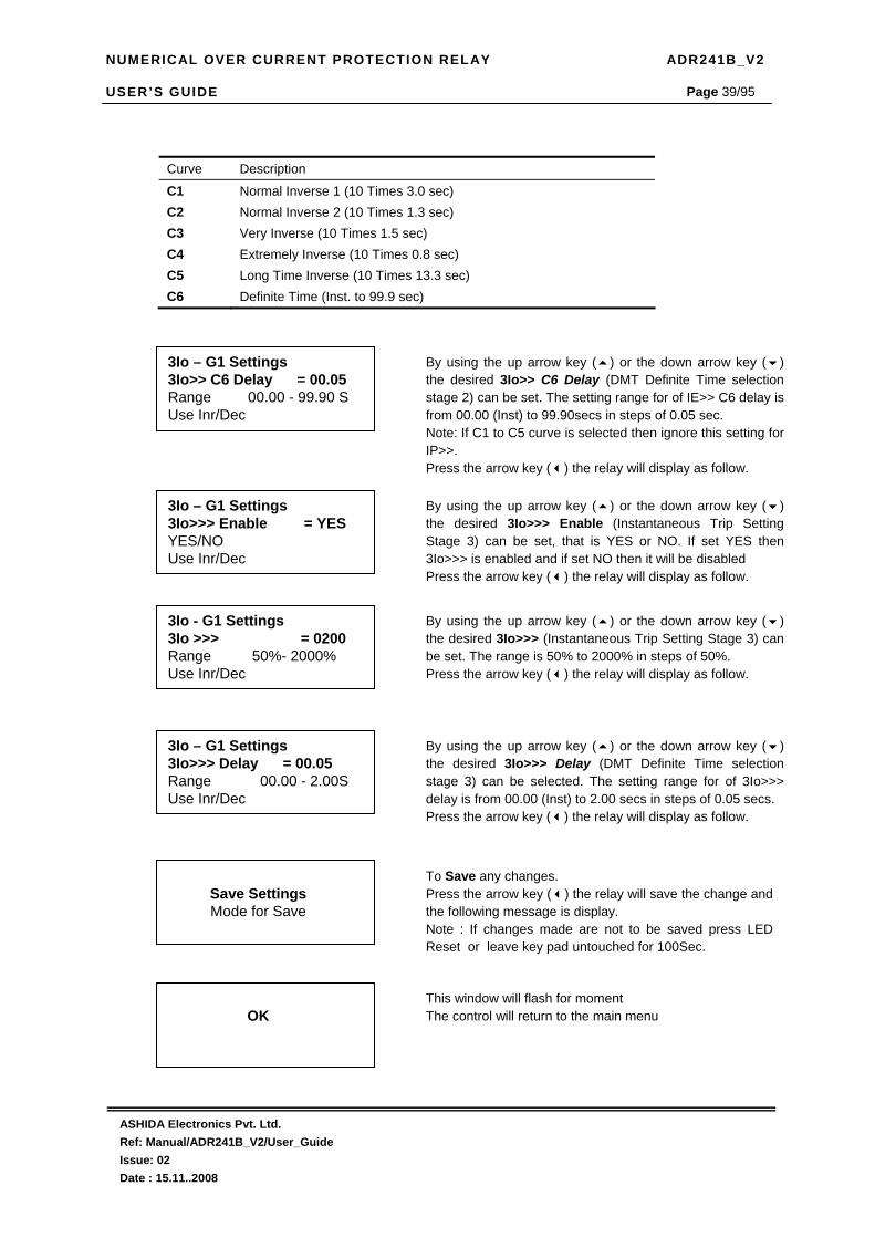
NUMERICAL OVER CURRENT PROTECTION RELAY ADR241B_V2 USER’S GUIDE
ASHIDA Electronics Pvt. Ltd. Ref: Manual/ADR241B_V2/User_Guide Issue: 02 Date : 15.11..2008
Page 39/95
Curve Description
C1 Normal Inverse 1 (10 Times 3.0 sec) C2 Normal Inverse 2 (10 Times 1.3 sec) C3 Very Inverse (10 Times 1.5 sec) C4 Extremely Inverse (10 Times 0.8 sec) C5 Long Time Inverse (10 Times 13.3 sec) C6 Definite Time (Inst. to 99.9 sec)
Save Settings Mode for Save
To Save any changes. Press the arrow key ( ) the relay will save the change and the following message is display. Note : If changes made are not to be saved press LED Reset or leave key pad untouched for 100Sec.
OK
This window will flash for moment The control will return to the main menu
3Io – G1 Settings 3Io>>> Enable = YES YES/NO Use Inr/Dec
By using the up arrow key ( ) or the down arrow key ( ) the desired 3Io>>> Enable (Instantaneous Trip Setting Stage 3) can be set, that is YES or NO. If set YES then 3Io>>> is enabled and if set NO then it will be disabled Press the arrow key ( ) the relay will display as follow.
3Io - G1 Settings 3Io >>> = 0200 Range 50%- 2000% Use Inr/Dec
By using the up arrow key ( ) or the down arrow key ( ) the desired 3Io>>> (Instantaneous Trip Setting Stage 3) can be set. The range is 50% to 2000% in steps of 50%. Press the arrow key ( ) the relay will display as follow.
3Io – G1 Settings 3Io>>> Delay = 00.05 Range 00.00 - 2.00S Use Inr/Dec
By using the up arrow key ( ) or the down arrow key ( ) the desired 3Io>>> Delay (DMT Definite Time selection stage 3) can be selected. The setting range for of 3Io>>> delay is from 00.00 (Inst) to 2.00 secs in steps of 0.05 secs. Press the arrow key ( ) the relay will display as follow.
3Io – G1 Settings 3Io>> C6 Delay = 00.05 Range 00.00 - 99.90 S Use Inr/Dec
By using the up arrow key ( ) or the down arrow key ( ) the desired 3Io>> C6 Delay (DMT Definite Time selection stage 2) can be set. The setting range for of IE>> C6 delay is from 00.00 (Inst) to 99.90secs in steps of 0.05 sec. Note: If C1 to C5 curve is selected then ignore this setting for IP>>. Press the arrow key ( ) the relay will display as follow.

NUMERICAL OVER CURRENT PROTECTION RELAY ADR241B_V2 USER’S GUIDE
ASHIDA Electronics Pvt. Ltd. Ref: Manual/ADR241B_V2/User_Guide Issue: 02 Date : 15.11..2008
Page 40/95
4.4.7.2 To View :– 3Io-G1 Setting
→ 3Io – G1 Setting ←
→ 3Io – G1 Setting ←
Press the arrow key ( ) the relay will display as follow.
3Io>=ON 3Io> = 0020 3Io > TMS = 01.00 3Io > Curve = 0001 3Io > C6 Delay = 00.05
This window will show 3Io Setting done previously. Press the arrow key ( ) the relay will display as follow.
3Io>>=ON 3Io> = 0020 3Io>> TMS = 01.00 3Io>> Curve = 0001 3Io>> C6 Delay = 00.05
This window will show 3Io Setting done previously. Press the arrow key ( ) the relay will display as follow.
3Io >>>=ON 3Io >>> = 200 3Io >>>Delay = 00.05
This window will show 3Io Setting done previously. Press the arrow key ( ) the relay will display the main menu.
→ 3Io – G1 Setting ←

NUMERICAL OVER CURRENT PROTECTION RELAY ADR241B_V2 USER’S GUIDE
ASHIDA Electronics Pvt. Ltd. Ref: Manual/ADR241B_V2/User_Guide Issue: 02 Date : 15.11..2008
Page 41/95
4.4.8 NEGATIVE PHASE SEQUENCE ELEMENT (NPS – G1) SETTINGS
4.4.8.1 To Set: – NPS – G1 Setting
NPS – G1 Settings I2>> Enable = YES YES/NO Use Inr/Dec
By using the up arrow key ( ) or the down arrow key ( ) the desired I2>> Enable (IDMT/DMT Trip setting stage 2) can be set, that is YES or NO. If set YES then IE>> is enabled and if set NO then it will be disabled. Press the arrow key ( ) the relay will display as follow.
NPS – G1 Settings I2>> = 0020 Range 10% - 200% Use Inr/Dec
By using the up arrow key ( ) or the down arrow key ( ) the desired I2>> (IDMT/DMT Trip setting stage 2) can be set. The range is 10% to 200% in steps of 1%. Press the arrow key ( ) the relay will display as follow.
NPS – G1 Settings I2>> TMS = 01.00 Range x0.02-x1.00 Use Inr/Dec
By using the up arrow key ( ) or the down arrow key ( ) the desired I2>> TMS (IDMT Time Multiplier Setting stage 2) can be set. The range is from x0.02 to x1.00 in steps of 0.01 Note: If C6 DMT Curve is selected then ignore this setting Press the arrow key ( ) the relay will display as follow.
NPS – G1 Settings I2>> Curve = 0001 Range C1-C6 Use Inr/Dec
By using the up arrow key ( ) or the down arrow key ( ) the desired I2>> Curve (IDMT/DMT Curve selection stage 2 can be set. Six different types of curves are provided C1 to C6. When the given value is 0001 Curve 1 is selected and when the given value 0002 Curve 2 is selected. In similar manner any desired curve can be selected as 0001 to 0006 correspond respectively with C1 to C6. Press the arrow key ( ) the relay will display as follow.
→ NPS - G1 Setting ←
Password protected window for “NPS – G1 Setting’’ for setting Password, I2>> Stage 2 Enable, I2>> Trip Setting, I2>> TMS, I2>> Curve Selection, I2>>C6 Delay, I2>>> Enable, I2>>> Instantaneous Element Trip setting, I2>>> Delay. Press the arrow key ( ) the relay will display as follow.
Password = 001 Use Inr/Dec
Enter the previously set password, By using the up arrow key or the down arrow key ( ). Note : Default password setting is ’0000’ Press the arrow key ( ) the relay will display as follow.

NUMERICAL OVER CURRENT PROTECTION RELAY ADR241B_V2 USER’S GUIDE
ASHIDA Electronics Pvt. Ltd. Ref: Manual/ADR241B_V2/User_Guide Issue: 02 Date : 15.11..2008
Page 42/95
Curve Description
C1 Normal Inverse 1 (10 Times 3.0 sec) C2 Normal Inverse 2 (10 Times 1.3 sec) C3 Very Inverse (10 Times 1.5 sec) C4 Extremely Inverse (10 Times 0.8 sec) C5 Long Time Inverse (10 Times 13.3 sec) C6 Definite Time (Inst. to 99.9 sec)
Save Settings Mode for Save
To Save any changes. Press the arrow key ( ) the relay will save the change and the following message is display. Note : If changes made are not to be saved press LED Reset or leave key pad untouched for 100 sec.
OK
This window will flash for moment The control will return to the main menu
NPS – G1 Settings I2>>> Enable = YES YES/NO Use Inr/Dec
By using the up arrow key ( ) or the down arrow key ( ) the desired I2>>> Enable (Instantaneous Trip Setting Stage 3) can be set, that is YES or NO. If set YES then it is enabled and if set NO then it will be disabled Press the arrow key ( ) the relay will display as follow.
NPS – G1 Settings I2>>> = 0200 Range 50%- 1500% Use Inr/Dec
By using the up arrow key ( ) or the down arrow key ( ) the desired I2>>> (Instantaneous Trip Setting Stage 3) can be set. The range is 50% to 1500% in steps of 50%. Press the arrow key ( ) the relay will display as follow.
NPS – G1 Settings I2>> C6 Delay = 00.05 Range 00.00 - 99.90 S Use Inr/Dec
By using the up arrow key ( ) or the down arrow key ( ) the desired I2>> C6 Delay (DMT Definite Time selection stage 2) can be set. The setting range is from 00.000 (Inst) to 99.90 secs in steps of 0.05sec. Note: If C1 to C5 curve is selected then ignore this setting Press the arrow key ( ) the relay will display as follow.
NPS – G1 Settings I2>>> Delay = 00.05 Range 00.00 - 2.00S Use Inr/Dec
By using the up arrow key ( ) or the down arrow key ( ) the desired I2>>> Delay (DMT Definite Time selection stage 3) can be selected. The setting range is from 00.00 (Inst) to 2.00 secs in steps of 0.05secs. This setting is effective only when C6 curve is selected Press the arrow key ( ) the relay will display as follow.

NUMERICAL OVER CURRENT PROTECTION RELAY ADR241B_V2 USER’S GUIDE
ASHIDA Electronics Pvt. Ltd. Ref: Manual/ADR241B_V2/User_Guide Issue: 02 Date : 15.11..2008
Page 43/95
4.4.8.2 To View:– NPS – G1 Setting
→ NPS – G1 Setting ←
→ NPS – G1 Setting ←
Press the arrow key ( ) the relay will display as follow.
I2>>=ON I2>> = 0020 I2>> TMS = 01.00 I2>> Curve = 0001 I2>> C6 Delay = 00.05
This window will show NPS Setting done previously. Press the arrow key ( ) the relay will display as follow.
I2>>>=ON I2>>> = 0200 I2>>>Delay = 00.05
This window will show NPS Setting done previously. Press the arrow key ( ) the relay will display the main menu.
→ NPS – G1 Setting ←

NUMERICAL OVER CURRENT PROTECTION RELAY ADR241B_V2 USER’S GUIDE
ASHIDA Electronics Pvt. Ltd. Ref: Manual/ADR241B_V2/User_Guide Issue: 02 Date : 15.11..2008
Page 44/95
4.4.9 OVER CURRENT (OC- G2) SETTINGS
4.4.9.1 To Set :– OC – G2 Setting
→ OC – G2 Setting ←
Password protected window for “OC - G2 Setting’’ for setting Password, IP> Stage1 Enable, IP> %Trip Setting, IP> TMS, IP> Curve selection, IP>C6 Delay, IP>> Stage 2 Enable, IP>> Trip Setting Stage 2, IP>> TMS, IP>> Curve selection, IP>>C6 Delay, IP>>> Stage 3 Enable, IP>>> Instantaneous Element Trip Setting , IP>>> Delay, Press the arrow key ( ) the relay will display as follow.
Password = 001 Use Inr/Dec
Enter the previously set password, By using the up arrow key or the down arrow key ( ). Note : Default password setting is ‘000’ Press the arrow key ( ) the relay will display as follow.
OC – G2 Settings IP> Enable = YES YES/NO Use Inr/Dec
By using the up arrow key ( ) or the down arrow key ( ) the desired IP> Enable (IDMT/DMT Trip setting stage 1) can be Enable / Disable that is YES / NO respectively. If set YES then IP> is enabled and if set NO then it will be disabled. Press the arrow key ( ) the relay will display as follow.
OC – G2 Settings IP> = 0020 Range 10%-200% Use Inr/Dec
By using the up arrow key ( ) or the down arrow key ( ) the desired IP> (IDMT/DMT Trip setting stage 1) can be set. The range is 10% to 200% in steps of 1%. Press the arrow key ( ) the relay will display as follow.
OC – G2 Settings IP> TMS = 01.00 Range x0.02-x1.00 Use Inr/Dec
By using the up arrow key ( ) or the down arrow key ( ) the desired IP> TMS (IDMT Time Multiplier Setting stage1 can be set. The range is from x0.02 to x1.00 in steps of 0.01 Note: If C6 DMT Curve is selected then ignore this setting Press the arrow key ( ) the relay will display as follow.
OC – G2 Settings IP> Curve = 0001 Range C1-C6 Use Inr/Dec
By using the up arrow key ( ) or the down arrow key ( ) the desired IP> Curve (IDMT/DMT Curve selection stage 1 can be set. Six different types of curves are provided C1 to C6. When the given value is 0001 Curve 1 is selected and when the given value 0002 Curve 2 is selected. In similar manner any desired curve can be selected as 0001 to 0006 correspond respectively with C1 to C6. Press the arrow key ( ) the relay will display as follow.

NUMERICAL OVER CURRENT PROTECTION RELAY ADR241B_V2 USER’S GUIDE
ASHIDA Electronics Pvt. Ltd. Ref: Manual/ADR241B_V2/User_Guide Issue: 02 Date : 15.11..2008
Page 45/95
Curve Description
C1 Normal Inverse 1 (10 Times 3.0 sec) C2 Normal Inverse 2 (10 Times 1.3 sec) C3 Very Inverse (10 Times 1.5 sec) C4 Extremely Inverse (10 Times 0.8 sec) C5 Long Time Inverse (10 Times 13.3 sec) C6 Definite Time (Inst. to 99.9 sec)
OC – G2 Settings IP> C6 Delay = 00.05 Range 00.00 - 99.90S Use Inr/Dec
By using the up arrow key ( ) or the down arrow key ( ) the desired IP> C6 Delay (DMT Definite Time selection stage 1) can be set. The setting range for of IP> C6 delay is from 00.00 (Inst) to 99.9secs in steps of 0.05 sec. Note: If C1 to C5 curve is selected then ignore this setting for IP> . Press the arrow key ( ) the relay will display as follow.
OC – G2 Settings IP>> Enable = YES YES/NO Use Inr/Dec
By using the up arrow key ( ) or the down arrow key ( ) the desired IP>> Enable (IDMT/DMT Trip setting stage 2) can be set, that is YES or NO. If set YES then IP>> is enabled and if set NO then it will be disabled. Press the arrow key ( ) the relay will display as follow.
OC – G2 Settings IP>> = 0020 Range 10%-200% Use Inr/Dec
By using the up arrow key ( ) or the down arrow key ( ) the desired IP>> (IDMT/DMT Trip setting stage 2) can be set. The range is 10% to 200% in steps of 1%. Press the arrow key ( ) the relay will display as follow.
OC – G2 Settings IP>> TMS = 01.00 Range x0.02-x1.00 Use Inr/Dec
By using the up arrow key ( ) or the down arrow key ( ) the desired IP>> TMS (IDMT Time multiply setting stage 2) can be set. The range is from x0.02 to x1.00 in steps of 0.01 Note: If C6 DMT Curve is selected then ignore this setting Press the arrow key ( ) the relay will display as follow.
OC – G2 Settings IP>> Curve = 0001 Range C1-C6 Use Inr/Dec
By using the up arrow key ( ) or the down arrow key ( ) the desired IP>> Curve (IDMT/DMT Curve selection stage 2) can be set. Six different types of curves are provided C1 to C6. When the given value is 0001 Curve 1 is selected and when the given value 0002 Curve 2 is selected. In similar manner any desired curve can be selected as 0001 to 0006 correspond respectively with C1 to C6. Press the arrow key ( ) the relay will display as follow.

NUMERICAL OVER CURRENT PROTECTION RELAY ADR241B_V2 USER’S GUIDE
ASHIDA Electronics Pvt. Ltd. Ref: Manual/ADR241B_V2/User_Guide Issue: 02 Date : 15.11..2008
Page 46/95
Curve Description
C1 Normal Inverse 1 (10 Times 3.0 sec) C2 Normal Inverse 2 (10 Times 1.3 sec) C3 Very Inverse (10 Times 1.5 sec) C4 Extremely Inverse (10 Times 0.8 sec) C5 Long Time Inverse (10 Times 13.3 sec) C6 Definite Time (Inst. to 99.9 sec)
OC – G2 Settings IP>>> Enable = YES YES/NO Use Inr/Dec
By using the up arrow key ( ) or the down arrow key ( ) the desired IP>>> Enable (Instantaneous Trip Setting Stage 3) can be set, that is YES or NO. If set YES then IP>>> is enabled and if set NO then it will be disabled Press the arrow key ( ) the relay will display as follow.
OC – G2 Settings IP>>> = 0200 Range 50%- 2000% Use Inr/Dec
By using the up arrow key ( ) or the down arrow key ( ) the desired IP>>> (Instantaneous Trip Setting Stage 3 can be set. The range is 50% to 2000% in steps of 50%. Press the arrow key ( ) the relay will display as follow.
OC – G2 Settings IP>> C6 Delay = 00.05 Range 00.00 - 99.90S Use Inr/Dec
By using the up arrow key ( ) or the down arrow key ( ) the desired IP>> C6 Delay (DMT Definite Time selection stage 2) can be set. The setting range for of IP>> C6 delay is from 00.00(Inst) to 99.9secs in steps of 0.05 sec. Note: If C1 to C5 curve is selected then ignore this setting for IP>>. Press the arrow key ( ) the relay will display as follow.
Save Settings Mode for Save
To Save any changes. Press the arrow key ( ) the relay will save the change and the following message is display. Note : If changes made are not to be saved press LED Reset or leave key pad untouched for 100Sec.
OK
This window will flash for moment The control will return to the main menu
OC – G2 Settings IP>>> Delay = 00.05 Range 00.00-2.00S Use Inr/Dec
By using the up arrow key ( ) or the down arrow key ( ) the desired IP>>> Delay (DMT Definite Time selection stage 3) can be selected. The setting range for of IP>>> delay is from00.00 (Inst) to 2.00secs in steps of 0.05secs. Press the arrow key ( ) the relay will display as follow.

NUMERICAL OVER CURRENT PROTECTION RELAY ADR241B_V2 USER’S GUIDE
ASHIDA Electronics Pvt. Ltd. Ref: Manual/ADR241B_V2/User_Guide Issue: 02 Date : 15.11..2008
Page 47/95
4.4.9.2 To View :– OC – G2 Settings
→ OC – G2 Settings ←
→ OC – G2 Setting ←
Press the arrow key ( ) the relay will display as follow.
IP>=ON IP> = 0020 IP> TMS = 01.00 IP> Curve = 0001 IP> C6 Delay = 00.05
This window will show OC Setting done previously. Press the arrow key ( ) the relay will display as follow.
IP>>=ON IP>> = 0020 IP>>TMS = 01.00 IP>> Curve = 0001 IP>> C6 Delay = 00.05
This window will show OC Setting done previously. Press the arrow key ( ) the relay will display as follow.
IP>>>=ON IP>>> = 0200 IP>>>Delay = 00.05
This window will show OC Setting done previously. Press the arrow key ( ) the relay will display the main menu.
→ OC – G2 Setting ←

NUMERICAL OVER CURRENT PROTECTION RELAY ADR241B_V2 USER’S GUIDE
ASHIDA Electronics Pvt. Ltd. Ref: Manual/ADR241B_V2/User_Guide Issue: 02 Date : 15.11..2008
Page 48/95
4.4.10 EARTH FAULT (EF – G2) SETTINGS
4.4.10.1 To Set:– EF – G2 Setting:
EF – G2 Settings IE> Enable = YES YES/NO Use Inr/Dec
By using the up arrow key ( ) or the down arrow key ( ) the desired IE> Enable (IDMT/DMT Trip setting stage 1) can be set, that is YES or NO. If set YES then IE> is enabled and if set NO then it will be disabled. Press the arrow key ( ) the relay will display as follow.
EF – G2 Settings IE> = 0020 Range 10% - 200% Use Inr/Dec
By using the up arrow key ( ) or the down arrow key ( ) the desired IE> (IDMT/DMT Trip setting stage 1) can be set. The range is 10% to 200% in steps of 1%. Press the arrow key ( ) the relay will display as follow.
EF – G2 Settings IE> TMS = 01.00 Range x0.02-x1.00 Use Inr/Dec
By using the up arrow key ( ) or the down arrow key ( ) the desired IE> TMS (IDMT Time multiply setting stage 1) can be set. The range is from x0.02 to x1.00 in steps of 0.01 Note: If C6 DMT Curve is selected then ignore this setting Press the arrow key ( ) the relay will display as follow.
EF – G2 Settings IE> Curve = 0001 Range C1-C6 Use Inr/Dec
By using the up arrow key ( ) or the down arrow key ( ) the desired IE> Curve (IDMT/DMT Curve selection stage 1) can be set. Six different types of curves are provided C1 to C6. When the given value is 0001 Curve 1 is selected and when the given value 0002 Curve 2 is selected. In similar manner any desired curve can be selected as 0001 to 0006 correspond respectively with C1 to C6. Press the arrow key ( ) the relay will display as follow.
→ EF – G2 Setting ←
Password protected window “EF – G2 Setting’’ for setting Password, IE> Enable, IE> Trip Setting Stage 1, IE> TMS, IE> Curve Selection, IE>C6 Delay, IE>> Enable, IE>> Trip Setting Stage 2, IE>> TMS, IE>> Curve Selection, IE>>C6 Delay, IE>>> Enable, IE>>> Trip setting High Set, IE>>> Delay. Press the arrow key ( ) the relay will display as follow.
Password = 001 Use Inr/Dec
Enter the previously y set password, By using the up arrow key or the down arrow key ( ). Note : Default password setting is ’0000’ Press the arrow key ( ) the relay will display as follow.

NUMERICAL OVER CURRENT PROTECTION RELAY ADR241B_V2 USER’S GUIDE
ASHIDA Electronics Pvt. Ltd. Ref: Manual/ADR241B_V2/User_Guide Issue: 02 Date : 15.11..2008
Page 49/95
Curve Description
C1 Normal Inverse 1 (10 Times 3.0 sec) C2 Normal Inverse 2 (10 Times 1.3 sec) C3 Very Inverse (10 Times 1.5 sec) C4 Extremely Inverse (10 Times 0.8 sec) C5 Long Time Inverse (10 Times 13.3 sec) C6 Definite Time (Inst. to 99.9 sec)
EF – G2 Settings IE> C6 Delay = 00.05 Range 00.00-99.90S Use Inr/Dec
By using the up arrow key ( ) or the down arrow key ( ) the desired IE> C6 Delay (DMT Definite Time selection stage 1) can be set. The setting range for of IE> C6 delay is from 00.00 (Inst) to 99.90 secs in steps of 0.05 sec. Note: If C1 to C5 curve is selected then ignore this setting for IE>. Press the arrow key ( ) the relay will display as follow.
EF – G2 Settings IE>> Enable = YES YES/NO Use Inr/Dec
By using the up arrow key ( ) or the down arrow key ( ) the desired IE>> Enable (IDMT/DMT Trip setting stage 2) can be set, that is YES or NO. If set YES then IE>> is enabled and if set NO then it will be disabled. Press the arrow key ( ) the relay will display as follow.
EF – G2 Settings IE>> = 0020 Range 10% - 200% Use Inr/Dec
By using the up arrow key ( ) or the down arrow key ( ) the desired IE>> (IDMT/DMT Trip setting stage 2) can be set. The range is 10% to 200% in steps of 1%. Press the arrow key ( ) the relay will display as follow.
EF – G2 Settings IE>> TMS = 01.00 Range x0.02-x1.00 Use Inr/Dec
By using the up arrow key ( ) or the down arrow key ( ) the desired IE>> TMS (IDMT Time Multiplier Setting stage 2 can be set. The range is from x0.02 to x1.00 in steps of 0.01 Note: If C6 DMT Curve is selected then ignore this setting Press the arrow key ( ) the relay will display as follow.
EF – G2 Settings IE>> Curve = 0001 Range C1-C6 Use Inr/Dec
By using the up arrow key ( ) or the down arrow key ( ) the desired IE>> Curve (IDMT/DMT Curve selection stage 2 can be set. Six different types of curves are provided C1 to C6. When the given value is 0001 Curve 1 is selected and when the given value 0002 Curve 2 is selected. In similar manner any desired curve can be selected as 0001 to 0006 correspond respectively with C1 to C6. Press the arrow key ( ) the relay will display as follow.
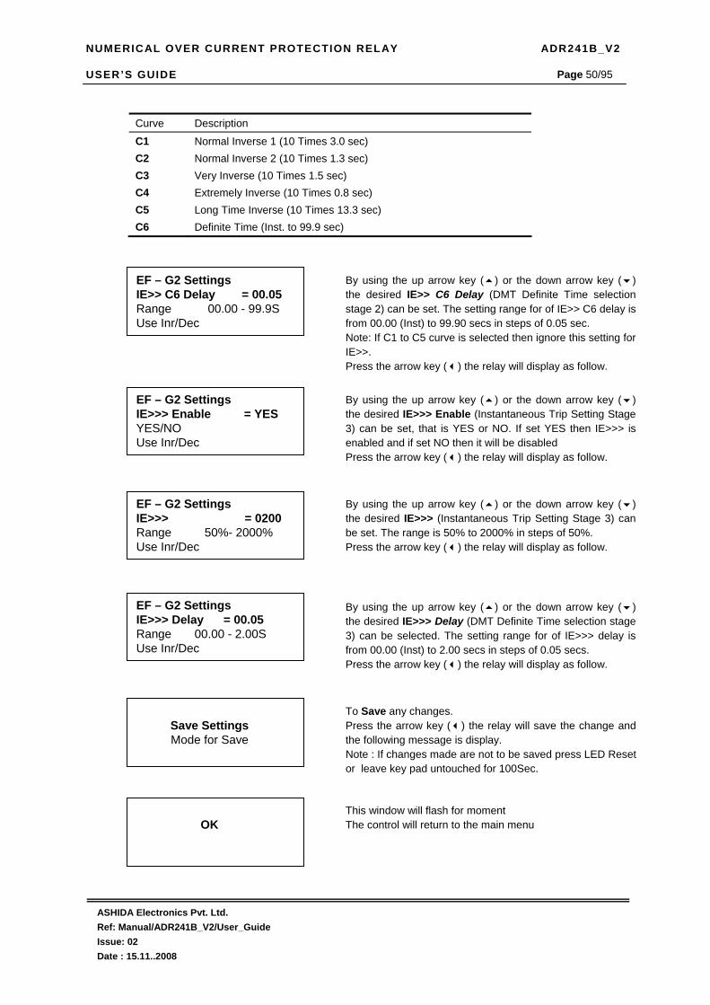
NUMERICAL OVER CURRENT PROTECTION RELAY ADR241B_V2 USER’S GUIDE
ASHIDA Electronics Pvt. Ltd. Ref: Manual/ADR241B_V2/User_Guide Issue: 02 Date : 15.11..2008
Page 50/95
Curve Description
C1 Normal Inverse 1 (10 Times 3.0 sec) C2 Normal Inverse 2 (10 Times 1.3 sec) C3 Very Inverse (10 Times 1.5 sec) C4 Extremely Inverse (10 Times 0.8 sec) C5 Long Time Inverse (10 Times 13.3 sec) C6 Definite Time (Inst. to 99.9 sec)
Save Settings Mode for Save
To Save any changes. Press the arrow key ( ) the relay will save the change and the following message is display. Note : If changes made are not to be saved press LED Reset or leave key pad untouched for 100Sec.
OK
This window will flash for moment The control will return to the main menu
EF – G2 Settings IE>>> Enable = YES YES/NO Use Inr/Dec
By using the up arrow key ( ) or the down arrow key ( ) the desired IE>>> Enable (Instantaneous Trip Setting Stage 3) can be set, that is YES or NO. If set YES then IE>>> is enabled and if set NO then it will be disabled Press the arrow key ( ) the relay will display as follow.
EF – G2 Settings IE>>> = 0200 Range 50%- 2000% Use Inr/Dec
By using the up arrow key ( ) or the down arrow key ( ) the desired IE>>> (Instantaneous Trip Setting Stage 3) can be set. The range is 50% to 2000% in steps of 50%. Press the arrow key ( ) the relay will display as follow.
EF – G2 Settings IE>>> Delay = 00.05 Range 00.00 - 2.00S Use Inr/Dec
By using the up arrow key ( ) or the down arrow key ( ) the desired IE>>> Delay (DMT Definite Time selection stage 3) can be selected. The setting range for of IE>>> delay is from 00.00 (Inst) to 2.00 secs in steps of 0.05 secs. Press the arrow key ( ) the relay will display as follow.
EF – G2 Settings IE>> C6 Delay = 00.05 Range 00.00 - 99.9S Use Inr/Dec
By using the up arrow key ( ) or the down arrow key ( ) the desired IE>> C6 Delay (DMT Definite Time selection stage 2) can be set. The setting range for of IE>> C6 delay is from 00.00 (Inst) to 99.90 secs in steps of 0.05 sec. Note: If C1 to C5 curve is selected then ignore this setting for IE>>. Press the arrow key ( ) the relay will display as follow.

NUMERICAL OVER CURRENT PROTECTION RELAY ADR241B_V2 USER’S GUIDE
ASHIDA Electronics Pvt. Ltd. Ref: Manual/ADR241B_V2/User_Guide Issue: 02 Date : 15.11..2008
Page 51/95
4.4.10.2 To View:– EF– G2 Setting
→ EF – G2 Setting ←
→ EF – G2 Setting ←
Press the arrow key ( ) the relay will display as follow.
IE>=ON IE> = 0020 IE> TMS = 01.00 IE> Curve = 0001 IE> C6 Delay = 00.05
This window will show EF Setting done previously. Press the arrow key ( ) the relay will display as follow.
IE>>=ON IE>> = 0020 IE>> TMS = 01.00 IE>> Curve = 0001 IE>> C6 Delay = 00.05
This window will show EF Setting done previously. Press the arrow key ( ) the relay will display as follow.
IE>>>=ON IE>>> = 0200 IE>>>Delay = 00.05
This window will show EF Setting done previously. Press the arrow key ( ) the relay will display the main menu.
→ EF – G2 Setting ←

NUMERICAL OVER CURRENT PROTECTION RELAY ADR241B_V2 USER’S GUIDE
ASHIDA Electronics Pvt. Ltd. Ref: Manual/ADR241B_V2/User_Guide Issue: 02 Date : 15.11..2008
Page 52/95
4.4.11 3Io – G2 SETTINGS
4.4.11.1 To Set: – 3Io – G2 Setting
3Io – G2 Settings 3Io> Enable = YES YES/NO Use Inr/Dec
By using the up arrow key ( ) or the down arrow key ( ) the desired 3Io> Enable (IDMT/DMT Trip setting stage 1) can be set, that is YES or NO. If set YES then 3Io> is enabled and if set NO then it will be disabled. Press the arrow key ( ) the relay will display as follow.
3Io – G2 Settings 3Io> = 0020 Range 10% - 200% Use Inr/Dec
By using the up arrow key ( ) or the down arrow key ( ) the desired 3Io> (IDMT/DMT Trip setting stage 1) can be set. The range is 10% to 200% in steps of 1%. Press the arrow key ( ) the relay will display as follow.
3Io – G2 Settings 3Io> TMS = 01.00 Range x0.02-x1.00 Use Inr/Dec
By using the up arrow key ( ) or the down arrow key ( ) the desired 3Io> TMS (IDMT Time multiply setting stage 1) can be set. The range is from x0.02 to x1.00 in steps of 0.01 Note: If C6 DMT Curve is selected then ignore this setting Press the arrow key ( ) the relay will display as follow.
3Io – G2 Settings 3Io> Curve = 0001 Range C1-C6 Use Inr/Dec
By using the up arrow key ( ) or the down arrow key ( ) the desired 3Io> Curve (IDMT/DMT Curve selection stage 1) can be set. Six different types of curves are provided C1 to C6. When the given value is 0001 Curve 1 is selected and when the given value 0002 Curve 2 is selected. In similar manner any desired curve can be selected as 0001 to 0006 correspond respectively with C1 to C6. Press the arrow key ( ) the relay will display as follow.
→ 3Io – G2 Setting ←
Password protected window for “3Io – G2 Setting’’ for setting Password, 3Io> Stage 1 Enable, 3Io> Trip Setting, 3Io> TMS, 3Io> Curve Selection, 3Io>C6 Delay, 3Io>> Enable, 3Io>> Trip Setting Stage 2, 3Io>> TMS, 3Io>> Curve Selection, 3Io>>C6 Delay, 3Io>>> Enable, 3Io>>> Trip setting High Set, 3Io >>> Delay. Press the arrow key ( ) the relay will display as follow.
Password = 001 Use Inr/Dec
Enter the previously y set password, By using the up arrow key ( ) or the down arrow key ( ). Note : Default password setting is ’0000’ Press the arrow key ( ) the relay will display as follow.

NUMERICAL OVER CURRENT PROTECTION RELAY ADR241B_V2 USER’S GUIDE
ASHIDA Electronics Pvt. Ltd. Ref: Manual/ADR241B_V2/User_Guide Issue: 02 Date : 15.11..2008
Page 53/95
Curve Description
C1 Normal Inverse 1 (10 Times 3.0 sec) C2 Normal Inverse 2 (10 Times 1.3 sec) C3 Very Inverse (10 Times 1.5 sec) C4 Extremely Inverse (10 Times 0.8 sec) C5 Long Time Inverse (10 Times 13.3 sec) C6 Definite Time (Inst. to 99.9 sec)
3Io – G2 Settings 3Io> C6 Delay = 00.05 Range 00.00 - 99.90S Use Inr/Dec
By using the up arrow key ( ) or the down arrow key ( ) the desired 3Io> C6 Delay (DMT Definite Time selection stage 1) can be set. The setting range for of IE> C6 delay is from 00.00 (Inst) to 99.90 secs in steps of 0.05 sec. Note: If C1 to C5 curve is selected then ignore this setting for 3IoI>. Press the arrow key ( ) the relay will display as follow.
3Io – G2 Settings 3Io>> Enable = YES YES/NO Use Inr/Dec
By using the up arrow key ( ) or the down arrow key ( ) the desired 3Io>> Enable (IDMT/DMT Trip setting stage 2) can be set, that is YES or NO. If set YES then 3Io >> is enabled and if set NO then it will be disabled. Press the arrow key ( ) the relay will display as follow.
3Io – G2 Settings 3Io>> = 0020 Range 10% - 200% Use Inr/Dec
By using the up arrow key ( ) or the down arrow key ( ) the desired 3Io>> (IDMT/DMT Trip setting stage 2) can be set. The range is 10% to 200% in steps of 1%. Press the arrow key ( ) the relay will display as follow.
3Io – G2 Settings 3Io>> TMS = 01.00 Range x0.02-x1.00 Use Inr/Dec
By using the up arrow key ( ) or the down arrow key ( ) the desired 3Io>> TMS (IDMT Time multiply setting stage 2) can be set. The range is from x0.02 to x1.00 in steps of 0.01 Note: If C6 DMT Curve is selected then ignore this setting Press the arrow key ( ) the relay will display as follow.
3Io – G2 Settings 3Io>> Curve = 0001 Range C1-C6 Use Inr/Dec
By using the up arrow key ( ) or the down arrow key ( ) the desired 3Io>> Curve (IDMT/DMT Curve selection stage 2) can be set. Six different types of curves are provided C1 to C6. When the given value is 0001 Curve 1 is selected and when the given value 0002 Curve 2 is selected. In similar manner any desired curve can be selected as 0001 to 0006 correspond respectively with C1 to C6. Press the arrow key ( ) the relay will display as follow.

NUMERICAL OVER CURRENT PROTECTION RELAY ADR241B_V2 USER’S GUIDE
ASHIDA Electronics Pvt. Ltd. Ref: Manual/ADR241B_V2/User_Guide Issue: 02 Date : 15.11..2008
Page 54/95
Curve Description
C1 Normal Inverse 1 (10 Times 3.0 sec) C2 Normal Inverse 2 (10 Times 1.3 sec) C3 Very Inverse (10 Times 1.5 sec) C4 Extremely Inverse (10 Times 0.8 sec) C5 Long Time Inverse (10 Times 13.3 sec) C6 Definite Time (Inst. to 99.9 sec)
Save Settings Mode for Save
To Save any changes. Press the arrow key ( ) the relay will save the change and the following message is display. Note : If changes made are not to be saved press LED Reset or leave key pad untouched for 100Sec.
OK
This window will flash for moment The control will return to the main menu
3Io – G2 Settings 3Io>>> Enable = YES YES/NO Use Inr/Dec
By using the up arrow key ( ) or the down arrow key ( ) the desired 3Io>>> Enable (Instantaneous Trip Setting Stage 3) can be set, that is YES or NO. If set YES then 3Io>>> is enabled and if set NO then it will be disabled Press the arrow key ( ) the relay will display as follow.
3Io – G2 Settings 3Io >>> = 0200 Range 50%- 2000% Use Inr/Dec
By using the up arrow key ( ) or the down arrow key ( ) the desired 3Io>>> (Instantaneous Trip Setting Stage 3) can be set. The range is 50% to 2000% in steps of 50%. Press the arrow key ( ) the relay will display as follow.
3Io – G2 Settings 3Io>>> Delay = 00.05 Range 00.00 - 2.00S Use Inr/Dec
By using the up arrow key ( ) or the down arrow key ( ) the desired 3Io>>> Delay (DMT Definite Time selection stage 3) can be selected. The setting range for of 3Io>>> delay is from 00.00 (Inst) to 2.00 secs in steps of 0.05 secs. Press the arrow key ( ) the relay will display as follow.
3Io – G2 Settings 3Io>> C6 Delay = 00.05 Range 00.00 - 99.90 S Use Inr/Dec
By using the up arrow key ( ) or the down arrow key ( ) the desired 3Io>> C6 Delay (DMT Definite Time selection stage 2) can be set. The setting range for of IE>> C6 delay is from 00.00 (Inst) to 99.90secs in steps of 0.05 sec. Note: If C1 to C5 curve is selected then ignore this setting for IP>>. Press the arrow key ( ) the relay will display as follow.

NUMERICAL OVER CURRENT PROTECTION RELAY ADR241B_V2 USER’S GUIDE
ASHIDA Electronics Pvt. Ltd. Ref: Manual/ADR241B_V2/User_Guide Issue: 02 Date : 15.11..2008
Page 55/95
4.4.11.2 To View :– 3Io - G2 Setting
→ 3Io – G2 Setting ←
→ 3Io – G2 Setting ←
Press the arrow key ( ) the relay will display as follow.
3Io>=ON 3Io> = 0020 3Io > TMS = 01.00 3Io > Curve = 0001 3Io > C6 Delay = 00.05
This window will show 3Io Setting done previously. Press the arrow key ( ) the relay will display as follow.
3Io>>=ON 3Io> = 0020 3Io>> TMS = 01.00 3Io>> Curve = 0001 3Io>> C6 Delay = 00.05
This window will show 3Io Setting done previously. Press the arrow key ( ) the relay will display as follow.
3Io >>>=ON 3Io >>> = 0200 3Io >>>Delay = 00.05
This window will show 3Io Setting done previously. Press the arrow key ( ) the relay will display the main menu.
→ 3Io – G2 Setting ←

NUMERICAL OVER CURRENT PROTECTION RELAY ADR241B_V2 USER’S GUIDE
ASHIDA Electronics Pvt. Ltd. Ref: Manual/ADR241B_V2/User_Guide Issue: 02 Date : 15.11..2008
Page 56/95
4.4.12 NEGATIVE PHASE SEQUENCE ELEMENT (NPS – G2) SETTINGS
4.4.12.1 To Set: – NPS – G2 Setting
NPS – G2 Settings I2>> Enable = YES YES/NO Use Inr/Dec
By using the up arrow key ( ) or the down arrow key ( ) the desired I2>> Enable (IDMT/DMT Trip setting stage 2) can be set, that is YES or NO. If set YES then IE>> is enabled and if set NO then it will be disabled. Press the arrow key ( ) the relay will display as follow.
NPS – G2 Settings I2>> = 0020 Range 10% - 200% Use Inr/Dec
By using the up arrow key ( ) or the down arrow key ( ) the desired I2>> (IDMT/DMT Trip setting stage 2) can be set. The range is 10% to 200% in steps of 1%. Press the arrow key ( ) the relay will display as follow.
NPS – G2 Settings I2>> TMS = 01.00 Range x0.02-x1.00 Use Inr/Dec
By using the up arrow key ( ) or the down arrow key ( ) the desired I2>> TMS (IDMT Time Multiplier Setting stage 2) can be set. The range is from x0.02 to x1.00 in steps of 0.01 Note: If C6 DMT Curve is selected then ignore this setting Press the arrow key ( ) the relay will display as follow.
NPS – G2 Settings I2>> Curve = 0001 Range C1-C6 Use Inr/Dec
By using the up arrow key ( ) or the down arrow key ( ) the desired I2>> Curve (IDMT/DMT Curve selection stage 2 can be set. Six different types of curves are provided C1 to C6. When the given value is 0001 Curve 1 is selected and when the given value 0002 Curve 2 is selected. In similar manner any desired curve can be selected as 0001 to 0006 correspond respectively with C1 to C6. Press the arrow key ( ) the relay will display as follow.
→ NPS – G2 Setting ←
Password protected window for “NPS – G2 Setting’’ forsetting Password, I2>> Stage 2 Enable, I2>> Trip Setting,I2>> TMS, I2>> Curve Selection, I2>>C6 Delay, I2>>>Enable, I2>>> Instantaneous Element Trip setting, I2>>>Delay. Press the arrow key ( ) the relay will display as follow.
Password = 001 Use Inr/Dec
Enter the previously y set password, By using the up arrow key or the down arrow key ( ). Note : Default password setting is ’0000’ Press the arrow key ( ) the relay will display as follow.

NUMERICAL OVER CURRENT PROTECTION RELAY ADR241B_V2 USER’S GUIDE
ASHIDA Electronics Pvt. Ltd. Ref: Manual/ADR241B_V2/User_Guide Issue: 02 Date : 15.11..2008
Page 57/95
Curve Description
C1 Normal Inverse 1 (10 Times 3.0 sec) C2 Normal Inverse 2 (10 Times 1.3 sec) C3 Very Inverse (10 Times 1.5 sec) C4 Extremely Inverse (10 Times 0.8 sec) C5 Long Time Inverse (10 Times 13.3 sec) C6 Definite Time (Inst. to 99.9 sec)
Save Settings Mode for Save
To Save any changes. Press the arrow key ( ) the relay will save the change and the following message is display. Note : If changes made are not to be saved press LED Reset or leave key pad untouched for 100 sec.
OK
This window will flash for moment The control will return to the main menu
NPS – G2 Settings I2>>> Enable = YES YES/NO Use Inr/Dec
By using the up arrow key ( ) or the down arrow key ( ) the desired I2>>> Enable (Instantaneous Trip Setting Stage 3) can be set, that is YES or NO. If set YES then it is enabled and if set NO then it will be disabled Press the arrow key ( ) the relay will display as follow.
NPS – G2 Settings I2>>> = 0200 Range 50%- 1500% Use Inr/Dec
By using the up arrow key ( ) or the down arrow key ( ) the desired I2>>> (Instantaneous Trip Setting Stage 3) can be set. The range is 50% to 1500% in steps of 50%. Press the arrow key ( ) the relay will display as follow.
NPS – G2 Settings I2>> C6 Delay = 00.05 Range 00.00 - 99.90 S Use Inr/Dec
By using the up arrow key ( ) or the down arrow key ( ) the desired I2>> C6 Delay (DMT Definite Time selection stage 2) can be set. The setting range is from 00.000 (Inst) to 99.90 secs in steps of 0.05sec. Note: If C1 to C5 curve is selected then ignore this setting Press the arrow key ( ) the relay will display as follow.
NPS – G2 Settings I2>>> Delay = 00.05 Range 00.00 - 2.00 S Use Inr/Dec
By using the up arrow key ( ) or the down arrow key ( ) the desired I2>>> Delay (DMT Definite Time selection stage 3) can be selected. The setting range is from 00.00 (Inst) to 2.00 secs in steps of 0.05secs. This setting is effective only when C6 curve is selected Press the arrow key ( ) the relay will display as follow.

NUMERICAL OVER CURRENT PROTECTION RELAY ADR241B_V2 USER’S GUIDE
ASHIDA Electronics Pvt. Ltd. Ref: Manual/ADR241B_V2/User_Guide Issue: 02 Date : 15.11..2008
Page 58/95
4.4.12.2 To View :– NPS – G2 Setting
→ NPS – G2 Setting ←
→ NPS – G2 Setting ←
Press the arrow key ( ) the relay will display as follow.
I2>>=ON I2>> = 0020 I2>> TMS = 01.00 I2>> Curve = 0001 I2>> C6 Delay = 00.05
This window will show NPS Setting done previously. Press the arrow key ( ) the relay will display as follow.
I2>>>=ON I2>>> = 0200 I2>>>Delay = 00.05
This window will show NPS Setting done previously. Press the arrow key ( ) the relay will display the main menu.
→ NPS – G2 Setting ←
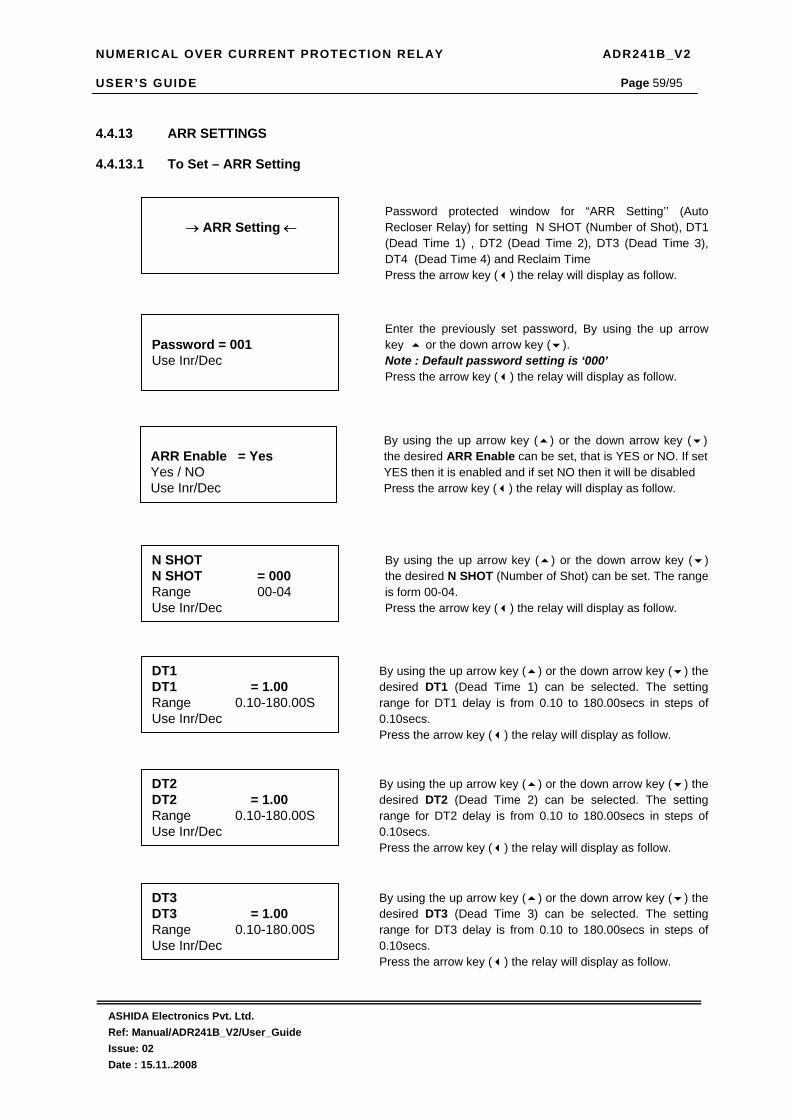
NUMERICAL OVER CURRENT PROTECTION RELAY ADR241B_V2 USER’S GUIDE
ASHIDA Electronics Pvt. Ltd. Ref: Manual/ADR241B_V2/User_Guide Issue: 02 Date : 15.11..2008
Page 59/95
4.4.13 ARR SETTINGS
4.4.13.1 To Set – ARR Setting
→ ARR Setting ←
Password protected window for “ARR Setting’’ (Auto Recloser Relay) for setting N SHOT (Number of Shot), DT1 (Dead Time 1) , DT2 (Dead Time 2), DT3 (Dead Time 3), DT4 (Dead Time 4) and Reclaim Time Press the arrow key ( ) the relay will display as follow.
Password = 001 Use Inr/Dec
Enter the previously set password, By using the up arrow key or the down arrow key ( ). Note : Default password setting is ‘000’ Press the arrow key ( ) the relay will display as follow.
N SHOT N SHOT = 000 Range 00-04 Use Inr/Dec
By using the up arrow key ( ) or the down arrow key ( ) the desired N SHOT (Number of Shot) can be set. The range is form 00-04. Press the arrow key ( ) the relay will display as follow.
DT1 DT1 = 1.00 Range 0.10-180.00S Use Inr/Dec
By using the up arrow key ( ) or the down arrow key ( ) the desired DT1 (Dead Time 1) can be selected. The setting range for DT1 delay is from 0.10 to 180.00secs in steps of 0.10secs. Press the arrow key ( ) the relay will display as follow.
DT2 DT2 = 1.00 Range 0.10-180.00S Use Inr/Dec
By using the up arrow key ( ) or the down arrow key ( ) the desired DT2 (Dead Time 2) can be selected. The setting range for DT2 delay is from 0.10 to 180.00secs in steps of 0.10secs. Press the arrow key ( ) the relay will display as follow.
DT3 DT3 = 1.00 Range 0.10-180.00S Use Inr/Dec
By using the up arrow key ( ) or the down arrow key ( ) the desired DT3 (Dead Time 3) can be selected. The setting range for DT3 delay is from 0.10 to 180.00secs in steps of 0.10secs. Press the arrow key ( ) the relay will display as follow.
ARR Enable = Yes Yes / NO Use Inr/Dec
By using the up arrow key ( ) or the down arrow key ( ) the desired ARR Enable can be set, that is YES or NO. If set YES then it is enabled and if set NO then it will be disabled Press the arrow key ( ) the relay will display as follow.
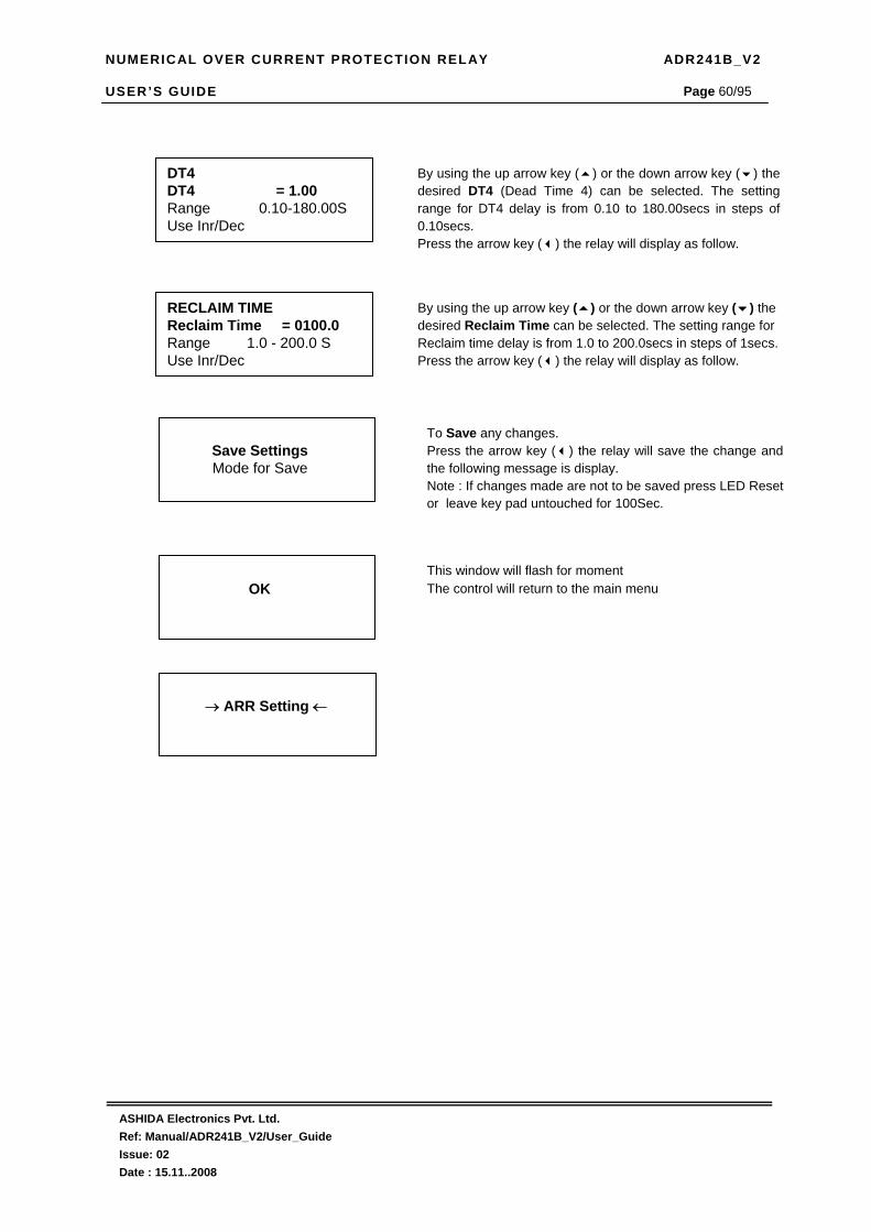
NUMERICAL OVER CURRENT PROTECTION RELAY ADR241B_V2 USER’S GUIDE
ASHIDA Electronics Pvt. Ltd. Ref: Manual/ADR241B_V2/User_Guide Issue: 02 Date : 15.11..2008
Page 60/95
DT4 DT4 = 1.00 Range 0.10-180.00S Use Inr/Dec
By using the up arrow key ( ) or the down arrow key ( ) the desired DT4 (Dead Time 4) can be selected. The setting range for DT4 delay is from 0.10 to 180.00secs in steps of 0.10secs. Press the arrow key ( ) the relay will display as follow.
RECLAIM TIME Reclaim Time = 0100.0 Range 1.0 - 200.0 S Use Inr/Dec
By using the up arrow key ( ) or the down arrow key ( ) the desired Reclaim Time can be selected. The setting range for Reclaim time delay is from 1.0 to 200.0secs in steps of 1secs. Press the arrow key ( ) the relay will display as follow.
Save Settings Mode for Save
To Save any changes. Press the arrow key ( ) the relay will save the change and the following message is display. Note : If changes made are not to be saved press LED Reset or leave key pad untouched for 100Sec.
OK
This window will flash for moment The control will return to the main menu
→ ARR Setting ←

NUMERICAL OVER CURRENT PROTECTION RELAY ADR241B_V2 USER’S GUIDE
ASHIDA Electronics Pvt. Ltd. Ref: Manual/ADR241B_V2/User_Guide Issue: 02 Date : 15.11..2008
Page 61/95
4.4.13.2 To View – ARR Setting
→ ARR Setting ←
Press the arrow key ( ) the relay will display as follow.
ARR = ON N SHOT = 004 DT1 = 001.00 DT2 = 001.00
This window will show ARR Setting done previously. Press the arrow key ( ) the relay will display as follow.
→ ARR Setting ←
DT3 = 001.00 DT4 = 001.00 Reclaim Time = 0100.0
This window will show ARR Setting done previously. Press the arrow key ( ) the relay will display the main menu.

NUMERICAL OVER CURRENT PROTECTION RELAY ADR241B_V2 USER’S GUIDE
ASHIDA Electronics Pvt. Ltd. Ref: Manual/ADR241B_V2/User_Guide Issue: 02 Date : 15.11..2008
Page 62/95
4.4.14 RELAY/LED CONFIGURATION Relay RL1 to RL5 and Dual LEDs L5 to L7 can be assign as 32 bit binary input for each Relay / LED . These 32 bit split into two ( A & B ) 16 bit binary input
which are required to transfer into Hexadecimal number to enter via Relays keypad and into Decimal number to enter via Relay Talk Software.
Any combination of listed Protection function & Digital input can be assign to Digital output relays RL1 TO RL5 and dual LEDs L5 , L6 & L7. These functions can
be assigning by relay front keypad and by Relay Talk Software.
4.4.14.1 Bit Definition for Relay/LED Configuration
Refer following table for each bit position corresponds to protection function and digital input. Bit Position 15 14 13 12 11 10 9 8 7 6 5 4 3 2 1 0
Weight of Bit 2^15 2^14 2^13 2^12 2^11 2^10 2^9 2^8 2^7 2^6 2^5 2^4 2^3 2^2 2^1 2^0
Relay(n) / LED(n) A
3Io>>> Ie>>> B>>> Y>>> R>>> I2>> 3Io>> Ie>> B>> Y>> R>> 3Io> Ie> B> Y> R>
Relay(n) / LED(n) B
SR/HR XX ArrDs ArrEn TC-F TC-H T2 T1 S5 S4 S3 S2 S1 OV UV I2>>>
Protection Function Bit information to assign
Set Bit Assign required protection function and digital input Binary ‘1’ to Set Bit
Reset Bit Assign required protection function and digital input Binary ‘0’ to Reset Bit
Self Reset ( SR ) Assign Bit no. 15 in Relay/LED B as Binary input ‘0’ to set selected function Self Reset.
Hand Reset ( HR ) Assign Bit no. 15 in Relay/LED B as Binary input ‘1’ to set selected function Hand Reset.
Not Applicable Bit no. 14 in Relay / LED B was not assigned to any protection function and digital function.
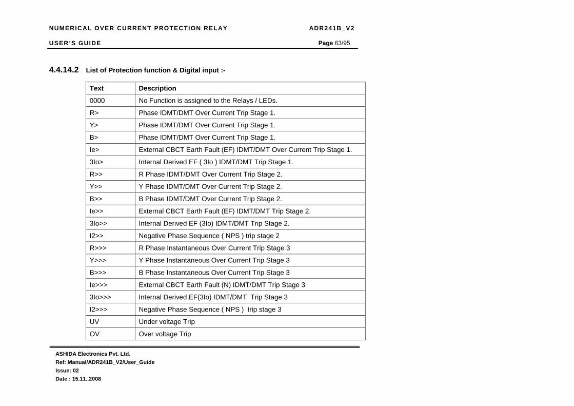
NUMERICAL OVER CURRENT PROTECTION RELAY ADR241B_V2 USER’S GUIDE
ASHIDA Electronics Pvt. Ltd. Ref: Manual/ADR241B_V2/User_Guide Issue: 02 Date : 15.11..2008
Page 63/95
4.4.14.2 List of Protection function & Digital input :-
Text Description
0000 No Function is assigned to the Relays / LEDs.
R> Phase IDMT/DMT Over Current Trip Stage 1.
Y> Phase IDMT/DMT Over Current Trip Stage 1.
B> Phase IDMT/DMT Over Current Trip Stage 1.
Ie> External CBCT Earth Fault (EF) IDMT/DMT Over Current Trip Stage 1.
3Io> Internal Derived EF ( 3Io ) IDMT/DMT Trip Stage 1.
R>> R Phase IDMT/DMT Over Current Trip Stage 2.
Y>> Y Phase IDMT/DMT Over Current Trip Stage 2.
B>> B Phase IDMT/DMT Over Current Trip Stage 2.
Ie>> External CBCT Earth Fault (EF) IDMT/DMT Trip Stage 2.
3Io>> Internal Derived EF (3Io) IDMT/DMT Trip Stage 2.
I2>> Negative Phase Sequence ( NPS ) trip stage 2
R>>> R Phase Instantaneous Over Current Trip Stage 3
Y>>> Y Phase Instantaneous Over Current Trip Stage 3
B>>> B Phase Instantaneous Over Current Trip Stage 3
Ie>>> External CBCT Earth Fault (N) IDMT/DMT Trip Stage 3
3Io>>> Internal Derived EF(3Io) IDMT/DMT Trip Stage 3
I2>>> Negative Phase Sequence ( NPS ) trip stage 3
UV Under voltage Trip
OV Over voltage Trip

NUMERICAL OVER CURRENT PROTECTION RELAY ADR241B_V2 USER’S GUIDE
ASHIDA Electronics Pvt. Ltd. Ref: Manual/ADR241B_V2/User_Guide Issue: 02 Date : 15.11..2008
Page 64/95
S1 S1 Digital Input to ON to any Relay / LEDs
S2 S2 Digital Input to ON to any Relay / LEDs
S3 S3 Digital Input to ON to any Relay / LEDs
S4 S4 Digital Input to ON to any Relay / LEDs
S5 S5 Digital Input to ON to any Relay / LEDs
T1 TC1(CB-NO) Trip Circuit Supervision Digital input
T2 TC2(CB-NC) Trip Circuit Digital input
TC-H Trip Circuit Supervision Healthy
TC-F Trip Circuit Supervision Faulty
Arr-En Auto Recloser Relay function Enable
Arr-Ds Auto Recloser Relay function Disable
SR / HR Relays / LED can be set Self Reset (SR) / Hand Reset.

NUMERICAL OVER CURRENT PROTECTION RELAY ADR241B_V2 USER’S GUIDE
ASHIDA Electronics Pvt. Ltd. Ref: Manual/ADR241B_V2/User_Guide Issue: 02 Date : 15.11..2008
Page 65/95
Refer following table for each bit position corresponds to protection function and digital input.
Bit Position 15 14 13 12 11 10 9 8 7 6 5 4 3 2 1 0
Weight of Bit 2^15 2^14 2^13 2^12 2^11 2^10 2^9 2^8 2^7 2^6 2^5 2^4 2^3 2^2 2^1 2^0
S1/S2/S3/S4/S5 XX XX XX XX XX XX XX XX XX XX XX XX XX G2 AB RR Protection Function Bit information to assign
Set Bit Assign required protection function and digital input Binary ‘1’ to Set Bit
Reset Bit Assign required protection function and digital input Binary ‘0’ to Reset Bit
RR Bit no. ‘0’ Remote Reset (RR) can be assign to any Status input.
AB Bit no. ‘1’ Auto Recloser Relay Block (AB) can be assign to any Status input.
G2 Bit no. ‘2’ can be assign to change Group 1 to Group 2 vise-versa by any Status input.
Not Applicable Bit no. 3 to 15 was not assign to any Status input.

NUMERICAL OVER CURRENT PROTECTION RELAY ADR241B_V2 USER’S GUIDE
ASHIDA Electronics Pvt. Ltd. Ref: Manual/ADR241B_V2/User_Guide Issue: 02 Date : 15.11..2008
Page 66/95
Refer following table for some equivalent Binary, Hex and Decimal values.
Binary Value Hex decimal Values Decimal Values
0000 0 0.
0001 1 1.
0010 2 2.
0011 3 3.
0100 4 4.
0101 5 5.
0110 6 6.
0111 7 7.
1000 8 8.
1001 9 9.
1010 A 10.
1011 B 11.
1100 C 12.
1101 D 13.
1110 E 14.
1111 F 15.

NUMERICAL OVER CURRENT PROTECTION RELAY ADR241B_V2 USER’S GUIDE
ASHIDA Electronics Pvt. Ltd. Ref: Manual/ADR241B_V2/User_Guide Issue: 02 Date : 15.11..2008
Page 67/95
4.4.14.3 To Set – Relay / LED Configuration :
→ Relay/LED Config ←
Password protected window for “Relay/LED Setting’’ for setting RL1, RL2, RL3, RL4, RL5, L5 Green, L5 Red, L6 Green, L6 Red, L7 Green, L7 Red, S1, S2, S3, S4 & S5. Press the arrow key ( ) the relay will display as follow.
Password = 001 Use Inr/Dec
Enter the previously y set password, By using the up arrow key or the down arrow key ( ). Note : Default password setting is ‘000’ Press the arrow key ( ) the relay will display as follow.
RL1 A = 0000 Use Inr/Dec
By using the up arrow key ( ) or the down arrow key ( ) the desired Function as per Hexadecimal number (0000 = Not Used) is assign to output relay RL1. This contact RL1 A is not assigned to any above listed function
RL1 B = 0000 Use Inr/Dec
By using the up arrow key ( ) or the down arrow key ( ) the desired Function as per Hexadecimal number (0000 = Not Used) is assign to output relay RL1. This contact RL1 B is not assigned to any above listed function
RL2 A = 0000 Use Inr/Dec
By using the up arrow key ( ) or the down arrow key ( ) the desired Function as per Hexadecimal number (0000 = Not Used) is assign to output relay RL2. This contact RL2 A is not assigned to any above listed function
RL2 B = 0000 Use Inr/Dec
By using the up arrow key ( ) or the down arrow key ( ) the desired Function as per Hexadecimal number (0000 = Not Used) is assign to output relay RL2. This contact RL2 B is not assigned to any above listed function
RL3 A = 0000 Use Inr/Dec
By using the up arrow key ( ) or the down arrow key ( ) the desired Function as per Hexadecimal number (0000 = Not Used) is assign to output relay RL3. This contact RL3 A is not assigned to any above listed function

NUMERICAL OVER CURRENT PROTECTION RELAY ADR241B_V2 USER’S GUIDE
ASHIDA Electronics Pvt. Ltd. Ref: Manual/ADR241B_V2/User_Guide Issue: 02 Date : 15.11..2008
Page 68/95
RL3 B = 0000 Use Inr/Dec
By using the up arrow key ( ) or the down arrow key ( ) the desired Function as per Hexadecimal number (0000 = Not Used) is assign to output relay RL3. This contact RL3 B is not assigned to any above listed function
RL4 B = 0000 Use Inr/Dec
By using the up arrow key ( ) or the down arrow key ( ) the desired Function as per Hexadecimal number (0000 = Not Used) is assign to output relay RL4. This contact RL4 B is not assigned to any above listed function
RL5 A = 0000 Use Inr/Dec
By using the up arrow key ( ) or the down arrow key ( ) the desired Function as per Hexadecimal number (0000 = Not Used) is assign to output relay RL5. This contact RL5 A is not assigned to any above listed function
RL5 B = 0000 Use Inr/Dec
By using the up arrow key ( ) or the down arrow key ( ) the desired Function as per Hexadecimal number (0000 = Not Used) is assign to output relay RL5. This contact RL5 B is not assigned to any above listed function
L5 Green A = 0000 Use Inr/Dec
By using the up arrow key ( ) or the down arrow key ( ) the desired Function as per Hexadecimal number (0000 = Not Used) is assign to output LED L5 Green. This contact L5 Green A is not assigned to any above listed function
L5 Green B = 0000 Use Inr/Dec
By using the up arrow key ( ) or the down arrow key ( ) the desired Function as per Hexadecimal number (0000 = Not Used) is assign to output LED L5 Green. This contact L5 Green B is not assigned to any above listed function
RL4 A = 0000 Use Inr/Dec
By using the up arrow key ( ) or the down arrow key ( ) the desired Function as per Hexadecimal number (0000 = Not Used) is assign to output relay RL4. This contact RL4 A is not assigned to any above listed function

NUMERICAL OVER CURRENT PROTECTION RELAY ADR241B_V2 USER’S GUIDE
ASHIDA Electronics Pvt. Ltd. Ref: Manual/ADR241B_V2/User_Guide Issue: 02 Date : 15.11..2008
Page 69/95
L5 Red A = 0000 Use Inr/Dec
By using the up arrow key ( ) or the down arrow key ( ) the desired Function as per Hexadecimal number (0000 = Not Used) is assign to output LED L5 Red. This contact L5 Red A is not assigned to any above listed function
L5 Red B = 0000 Use Inr/Dec
By using the up arrow key ( ) or the down arrow key ( ) the desired Function as per Hexadecimal number (0000 = Not Used) is assign to output LED L5 Red. This contact L5 Red B is not assigned to any above listed function
L6 Green A = 0000 Use Inr/Dec
By using the up arrow key ( ) or the down arrow key ( ) the desired Function as per Hexadecimal number (0000 = Not Used) is assign to output LED L6 Green. This contact L6 Green A is not assigned to any above listed function
L6 Green B = 0000 Use Inr/Dec
By using the up arrow key ( ) or the down arrow key ( ) the desired Function as per Hexadecimal number (0000 = Not Used) is assign to output LED L6 Green. This contact L6 Green B is not assigned to any above listed function
L6 Red A = 0000 Use Inr/Dec
By using the up arrow key ( ) or the down arrow key ( ) the desired Function as per Hexadecimal number (0000 = Not Used) is assign to output LED L6 Red. This contact L6 Red A is not assigned to any above listed function
L6 Red B = 0000 Use Inr/Dec
By using the up arrow key (() or the down arrow key (() the desired Function as per Hexadecimal number (0000 = Not Used) is assign to output LED L6 Red. This contact L6 Red B is not assigned to any above listed function
L7 Green A = 0000 Use Inr/Dec
By using the up arrow key ( ) or the down arrow key ( ) the desired Function as per Hexadecimal number (0000 = Not Used) is assign to output LED L7 Green. This contact L7 Green A is not assigned to any above listed function

NUMERICAL OVER CURRENT PROTECTION RELAY ADR241B_V2 USER’S GUIDE
ASHIDA Electronics Pvt. Ltd. Ref: Manual/ADR241B_V2/User_Guide Issue: 02 Date : 15.11..2008
Page 70/95
S1 = 0000 Use Inr/Dec
By using the up arrow key ( ) or the down arrow key ( ) the desired Function (as per Hexadecimal number (0000 = Not Used) is assign to Status Input S1. This contact S1 is not assigned to any above listed function
L7 Green B = 0000 Use Inr/Dec
By using the up arrow key ( ) or the down arrow key ( ) the desired Function as per Hexadecimal number (0000 = Not Used) is assign to output LED L7 Green. This contact L7 Green B is not assigned to any above listed function
L7 Red A = 0000 Use Inr/Dec
By using the up arrow key ( ) or the down arrow key ( ) the desired Function as per Hexadecimal number (0000 = Not Used) is assign to output LED L7 Red. This contact L7 Red A is not assigned to any above listed function
L7 Red B = 0000 Use Inr/Dec
By using the up arrow key ( ) or the down arrow key ( ) the desired Function as per Hexadecimal number (0000 = Not Used) is assign to output LED L7 Red. This contact L7 Red B is not assigned to any above listed function
S2 = 0000 Use Inr/Dec
By using the up arrow key ( ) or the down arrow key ( ) the desired Function (as per Hexadecimal number (0000 = Not Used) is assign to Status Input S2. This contact S2 is not assigned to any above listed function
S3 = 0000 Use Inr/Dec
By using the up arrow key ( ) or the down arrow key ( ) the desired Function (as per Hexadecimal number (0000 = Not Used) is assign to Status Input S3. This contact S3 is not assigned to any above listed function
S4 = 0000 Use Inr/Dec
By using the up arrow key ( ) or the down arrow key ( ) the desired Function (as per Hexadecimal number (0000 = Not Used) is assign to Status Input S4. This contact S4 is not assigned to any above listed function

NUMERICAL OVER CURRENT PROTECTION RELAY ADR241B_V2 USER’S GUIDE
ASHIDA Electronics Pvt. Ltd. Ref: Manual/ADR241B_V2/User_Guide Issue: 02 Date : 15.11..2008
Page 71/95
Save Settings Mode for Save
To Save any changes. Press the arrow key ( ) the relay will save the change and the following message is display. Note: If changes made are not to be saved press LED Reset or leave key pad untouched for 100Sec.
OK
This window will flash for moment The control will return to the main menu
→ Relay/LED Config ←
S5 = 0000 Use Inr/Dec
By using the up arrow key ( ) or the down arrow key ( ) the desired Function (as per Hexadecimal number (0000 = Not Used) is assign to Status Input S5. This contact S5 is not assigned to any above listed function

NUMERICAL OVER CURRENT PROTECTION RELAY ADR241B_V2 USER’S GUIDE
ASHIDA Electronics Pvt. Ltd. Ref: Manual/ADR241B_V2/User_Guide Issue: 02 Date : 15.11..2008
Page 72/95
4.4.14.4 To View – Relay / LED Configuration :
→ Relay/LED Config ←
Press the arrow key ( ) the relay will display as follow.
RL1 A = 0000 RL1 B = 0000 RL2 A = 0000 RL2 B = 0000
This window will show Relay/LED Config Setting done previously. Press the arrow key ( ) the relay will display as follow.
RL3 A = 0000 RL3 B = 0000 RL4 A = 0000 RL4 B = 0000
This window will show Relay/LED Config Setting done previously. Press the arrow key ( ) the relay will display as follow.
RL5 A = 0000 RL5 B = 0000 L5 Green A = 0000 L5 Green B = 0000
This window will show Relay/LED Config Setting done previously. Press the arrow key ( ) the relay will display as follow.
L5 Red A = 0000 L5 Red B = 0000 L6 Green A = 0000 L6 Green B = 0000
This window will show Relay/LED Config Setting done previously. Press the arrow key ( ) the relay will display as follow.
L6 Red A = 0000 L6 Red B = 0000 L7 Green A = 0000 L7 Green B = 0000
This window will show Relay/LED Config Setting done previously. Press the arrow key ( ) the relay will display as follow.
L7 Red A = 0000 L7 Red B = 0000 S1 = 0000 S2 = 0000
This window will show Relay/LED Config Setting done previously. Press the arrow key ( ) the relay will display as follow.
→ Relay/LED Config ←
S3 = 0000 S4 = 0000 S5 = 0000
This window will show Relay/LED Config Setting done previously. Press the arrow key ( ) the relay will display as follow.

NUMERICAL OVER CURRENT PROTECTION RELAY ADR241B_V2 USER’S GUIDE
ASHIDA Electronics Pvt. Ltd. Ref: Manual/ADR241B_V2/User_Guide Issue: 02 Date : 15.11..2008
Page 73/95
4.4.14.5 Example of Relay / LED configuration. :-
1. Suppose RL 1 required to configure with manual reset : R>>, Y>>, B>>
2. Suppose RL 2 required to configure manual reset: R>>>, Y>>>, B>>>
3. Suppose RL 3 required to configure manual reset : 3Io>>,EF>>, I2>>
4. Suppose RL 4 required to configure manual reset : 3Io>>>,EF>>>, I2>>>
5. Suppose RL 5 required to configure manual reset : R>, Y>, B>,3Io>,EF>
6. Suppose L5 Green required configure for C.B. OFF monitor via T2 self reset: T2
As T2 = ON = C.B. OFF
7. Suppose L5 Red required to configure for C.B. ON monitor via T1 self reset : T1
As T1 = ON = C.B. ON
8. Suppose L6 Green required to configure for Spring Charge monitor via S1 self reset : S1
As S1 = ON = Spring Charge
9. Suppose L6 Red required to configure for Spring Discharge monitor via S2 self reset : S2
As S2 = ON = Spring Discharge
10. Suppose L7 Green required to configure for IDMT Trip manual reset : R>>, Y>>, B>>, 3Io>>,EF>>, I2>>
11. Suppose L7 Red required to configure for Instantaneous Trip manual reset : R>>>, Y>>>, B>>>, 3Io>>>,EF>>>, I2>>>
12. Suppose S3 Status input required to configure for Remote Reset ( RR ) : S3
13. Suppose S4 Status input required to configure for Auto Recolser Relay Block ( AB ) : S4
14. Suppose S5 Status input required to configure for Group Change ( G2 ) : S5

NUMERICAL OVER CURRENT PROTECTION RELAY ADR241B_V2 USER’S GUIDE
ASHIDA Electronics Pvt. Ltd. Ref: Manual/ADR241B_V2/User_Guide Issue: 02 Date : 15.11..2008
Page 74/95
Calculation to configure above protection function & status input : 1. Suppose RL 1 required to configure : R>>, Y>>, B>> Bit Position 15 14 13 12 11 10 9 8 7 6 5 4 3 2 1 0
Weight of Bit 2^15 2^14 2^13 2^12 2^11 2^10 2^9 2^8 2^7 2^6 2^5 2^4 2^3 2^2 2^1 2^0 Relay(n) / LED(n) A
3Io>>> Ie>>> B>>> Y>>> R>>> I2>> 3Io>> Ie>>
B>> Y>> R>> 3Io> Ie> B> Y> R>
Set Bit 0 0 0 0 0 0 0 0 1 1 1 0 0 0 0 0 Equivalent Hex No.
0 0 E 0
* Equivalent Decimal No. Calculation
2^7 128+
2^6 64+
2^5 32=
224
Equivalent Decimal No
224
Relay(n) / LED(n) B
SR/HR XX ArrDs ArrEn TC-F TC-H T2 T1 S5 S4 S3 S2 S1 OV UV I2>>>
Set Bit 1 0 0 0 0 0 0 0 0 0 0 0 0 0 0 0 Equivalent Hex No.
8 0 0 0
* Equivalent Decimal No. Calculation
2^15 32768=
32768
Equivalent Decimal No
32768
Set RL1 A = 00E0 Enter by Relay front PCB = 224 Enter by Relay Talk Software RL1 B = 8000 Enter by Relay front PCB = 32768 Enter by Relay Talk Software Note :- * ‘Equivalent Decimal No. Calculation’ was applicable only when ‘Set Bit’ = 1
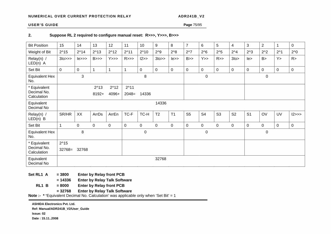
NUMERICAL OVER CURRENT PROTECTION RELAY ADR241B_V2 USER’S GUIDE
ASHIDA Electronics Pvt. Ltd. Ref: Manual/ADR241B_V2/User_Guide Issue: 02 Date : 15.11..2008
Page 75/95
2. Suppose RL 2 required to configure manual reset: R>>>, Y>>>, B>>> Bit Position 15 14 13 12 11 10 9 8 7 6 5 4 3 2 1 0
Weight of Bit 2^15 2^14 2^13 2^12 2^11 2^10 2^9 2^8 2^7 2^6 2^5 2^4 2^3 2^2 2^1 2^0
Relay(n) / LED(n) A
3Io>>> Ie>>> B>>> Y>>> R>>> I2>> 3Io>> Ie>> B>> Y>> R>> 3Io> Ie> B> Y> R>
Set Bit 0 0 1 1 1 0 0 0 0 0 0 0 0 0 0 0
Equivalent Hex No.
3 8 0 0
* Equivalent Decimal No. Calculation
2^13 8192+
2^12 4096+
2^11 2048=
14336
Equivalent Decimal No
14336
Relay(n) / LED(n) B
SR/HR XX ArrDs ArrEn TC-F TC-H T2 T1 S5 S4 S3 S2 S1 OV UV I2>>>
Set Bit 1 0 0 0 0 0 0 0 0 0 0 0 0 0 0 0
Equivalent Hex No.
8 0 0 0
* Equivalent Decimal No. Calculation
2^15 32768=
32768
Equivalent Decimal No
32768
Set RL1 A = 3800 Enter by Relay front PCB = 14336 Enter by Relay Talk Software RL1 B = 8000 Enter by Relay front PCB = 32768 Enter by Relay Talk Software Note :- * ‘Equivalent Decimal No. Calculation’ was applicable only when ‘Set Bit’ = 1

NUMERICAL OVER CURRENT PROTECTION RELAY ADR241B_V2 USER’S GUIDE
ASHIDA Electronics Pvt. Ltd. Ref: Manual/ADR241B_V2/User_Guide Issue: 02 Date : 15.11..2008
Page 76/95
3. Suppose RL 3 required to configure manual reset : 3Io>>,EF>>, I2>> Bit Position 15 14 13 12 11 10 9 8 7 6 5 4 3 2 1 0
Weight of Bit 2^15 2^14 2^13 2^12 2^11 2^10 2^9 2^8 2^7 2^6 2^5 2^4 2^3 2^2 2^1 2^0
Relay(n) / LED(n) A
3Io>>> Ie>>> B>>> Y>>> R>>> I2>> 3Io>> Ie>> B>> Y>> R>> 3Io> Ie> B> Y> R>
Set Bit 0 0 0 0 0 1 1 1 0 0 0 0 0 0 0 0
Equivalent Hex No.
0 7 0 0
* Equivalent Decimal No. Calculation
2^10 1024+
2^9 512+
2^8 256=
1792
Equivalent Decimal No
1792
Relay(n) / LED(n) B
SR/HR XX ArrDs ArrEn TC-F TC-H T2 T1 S5 S4 S3 S2 S1 OV UV I2>>>
Set Bit 1 0 0 0 0 0 0 0 0 0 0 0 0 0 0 0
Equivalent Hex No.
8 0 0 0
* Equivalent Decimal No. Calculation
2^15 32768=
32768
Equivalent Decimal No
32768
Set RL3 A = 0700 Enter by Relay front PCB = 1792 Enter by Relay Talk Software RL3 B = 8000 Enter by Relay front PCB = 32768 Enter by Relay Talk Software Note :- * ‘Equivalent Decimal No. Calculation’ was applicable only when ‘Set Bit’ = 1
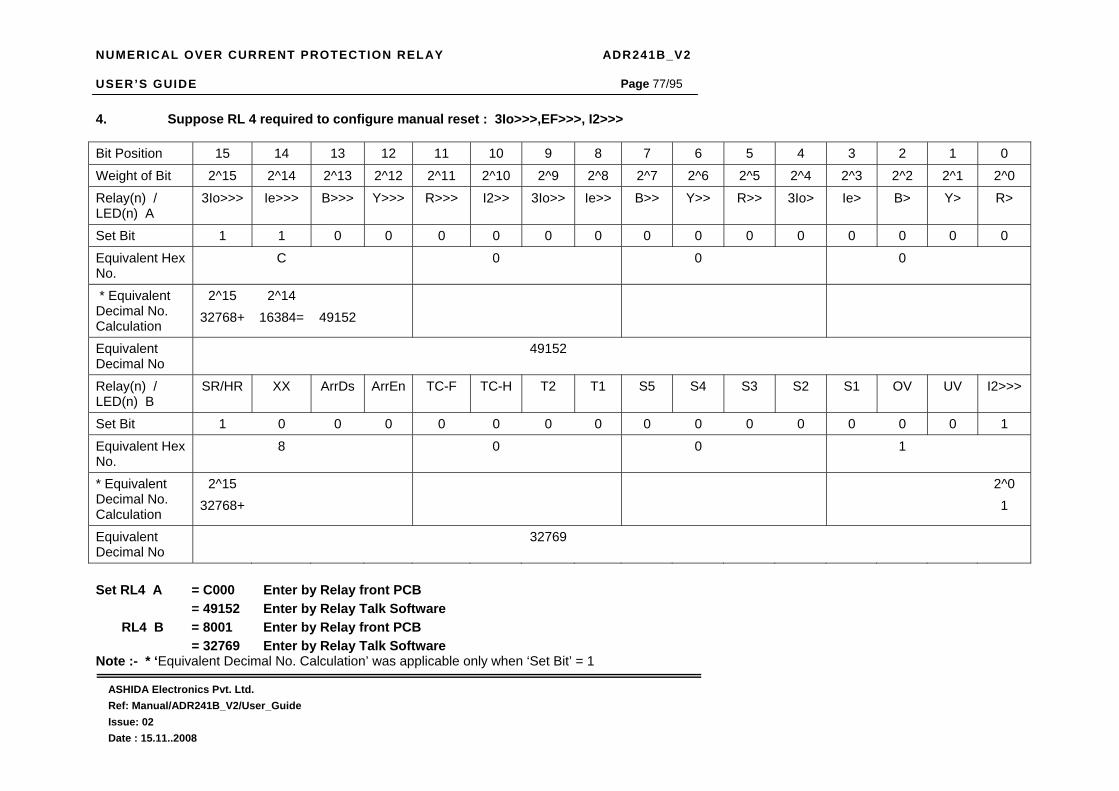
NUMERICAL OVER CURRENT PROTECTION RELAY ADR241B_V2 USER’S GUIDE
ASHIDA Electronics Pvt. Ltd. Ref: Manual/ADR241B_V2/User_Guide Issue: 02 Date : 15.11..2008
Page 77/95
4. Suppose RL 4 required to configure manual reset : 3Io>>>,EF>>>, I2>>> Bit Position 15 14 13 12 11 10 9 8 7 6 5 4 3 2 1 0
Weight of Bit 2^15 2^14 2^13 2^12 2^11 2^10 2^9 2^8 2^7 2^6 2^5 2^4 2^3 2^2 2^1 2^0
Relay(n) / LED(n) A
3Io>>> Ie>>> B>>> Y>>> R>>> I2>> 3Io>> Ie>> B>> Y>> R>> 3Io> Ie> B> Y> R>
Set Bit 1 1 0 0 0 0 0 0 0 0 0 0 0 0 0 0
Equivalent Hex No.
C 0 0 0
* Equivalent Decimal No. Calculation
2^15 32768+
2^14 16384=
49152
Equivalent Decimal No
49152
Relay(n) / LED(n) B
SR/HR XX ArrDs ArrEn TC-F TC-H T2 T1 S5 S4 S3 S2 S1 OV UV I2>>>
Set Bit 1 0 0 0 0 0 0 0 0 0 0 0 0 0 0 1
Equivalent Hex No.
8 0 0 1
* Equivalent Decimal No. Calculation
2^15 32768+
2^0 1
Equivalent Decimal No
32769
Set RL4 A = C000 Enter by Relay front PCB = 49152 Enter by Relay Talk Software RL4 B = 8001 Enter by Relay front PCB = 32769 Enter by Relay Talk Software Note :- * ‘Equivalent Decimal No. Calculation’ was applicable only when ‘Set Bit’ = 1

NUMERICAL OVER CURRENT PROTECTION RELAY ADR241B_V2 USER’S GUIDE
ASHIDA Electronics Pvt. Ltd. Ref: Manual/ADR241B_V2/User_Guide Issue: 02 Date : 15.11..2008
Page 78/95
5. Suppose RL 5 required to configure manual reset : R>, Y>, B>,3Io>,EF> Bit Position 15 14 13 12 11 10 9 8 7 6 5 4 3 2 1 0
Weight of Bit 2^15 2^14 2^13 2^12 2^11 2^10 2^9 2^8 2^7 2^6 2^5 2^4 2^3 2^2 2^1 2^0
Relay(n) / LED(n) A
3Io>>> Ie>>> B>>> Y>>> R>>> I2>> 3Io>> Ie>> B>> Y>> R>> 3Io> Ie> B> Y> R>
Set Bit 0 0 0 0 0 0 0 0 0 0 0 1 1 1 1 1
Equivalent Hex No.
0 0 1 F
* Equivalent Decimal No. Calculation
2^4 16
2^3 8
2^2 4
2^1 2
2^0 1
Equivalent Decimal No
31
Relay(n) / LED(n) B
SR/HR XX ArrDs ArrEn TC-F TC-H T2 T1 S5 S4 S3 S2 S1 OV UV I2>>>
Set Bit 1 0 0 0 0 0 0 0 0 0 0 0 0 0 0 0
Equivalent Hex No.
8 0 0 0
* Equivalent Decimal No. Calculation
2^15 32768=
32768
Equivalent Decimal No
32768
Set RL5 A = 001F Enter by Relay front PCB = 31 Enter by Relay Talk Software RL5 B = 8000 Enter by Relay front PCB = 32768 Enter by Relay Talk Software Note :- * ‘Equivalent Decimal No. Calculation’ was applicable only when ‘Set Bit’ = 1

NUMERICAL OVER CURRENT PROTECTION RELAY ADR241B_V2 USER’S GUIDE
ASHIDA Electronics Pvt. Ltd. Ref: Manual/ADR241B_V2/User_Guide Issue: 02 Date : 15.11..2008
Page 79/95
6. Suppose L5 Green required configure for C.B. OFF monitor via T2 self reset: T2
As T2 = ON = C.B. OFF
Bit Position 15 14 13 12 11 10 9 8 7 6 5 4 3 2 1 0
Weight of Bit 2^15 2^14 2^13 2^12 2^11 2^10 2^9 2^8 2^7 2^6 2^5 2^4 2^3 2^2 2^1 2^0
Relay(n) / LED(n) A
3Io>>> Ie>>> B>>> Y>>> R>>> I2>> 3Io>> Ie>> B>> Y>> R>> 3Io> Ie> B> Y> R>
Set Bit 0 0 0 0 0 0 0 0 0 0 0 0 0 0 0 0
Equivalent Hex No.
0 0 0 0
* Equivalent Decimal No. Calculation
Equivalent Decimal No
0
Relay(n) / LED(n) B
SR/HR XX ArrDs ArrEn TC-F TC-H T2 T1 S5 S4 S3 S2 S1 OV UV I2>>>
Set Bit 0 0 0 0 0 0 1 0 0 0 0 0 0 0 0 0
Equivalent Hex No.
0 2 0 0
* Equivalent Decimal No. Calculation
2^9 512=
512
Equivalent Decimal No
512
Set L5 Green A = 0000 Enter by Relay front PCB = 0 Enter by Relay Talk Software L5 Green B = 0200 Enter by Relay front PCB = 512 Enter by Relay Talk Software Note :- * ‘Equivalent Decimal No. Calculation’ was applicable only when ‘Set Bit’ = 1

NUMERICAL OVER CURRENT PROTECTION RELAY ADR241B_V2 USER’S GUIDE
ASHIDA Electronics Pvt. Ltd. Ref: Manual/ADR241B_V2/User_Guide Issue: 02 Date : 15.11..2008
Page 80/95
7. Suppose L5 Red required to configure for C.B. ON monitor via T1 self reset : T1
As T1 = ON = C.B. ON
Bit Position 15 14 13 12 11 10 9 8 7 6 5 4 3 2 1 0
Weight of Bit 2^15 2^14 2^13 2^12 2^11 2^10 2^9 2^8 2^7 2^6 2^5 2^4 2^3 2^2 2^1 2^0
Relay(n) / LED(n) A
3Io>>> Ie>>> B>>> Y>>> R>>> I2>> 3Io>> Ie>> B>> Y>> R>> 3Io> Ie> B> Y> R>
Set Bit 0 0 0 0 0 0 0 0 0 0 0 0 0 0 0 0
Equivalent Hex No.
0 0 0 0
* Equivalent Decimal No. Calculation
Equivalent Decimal No
0
Relay(n) / LED(n) B
SR/HR XX ArrDs ArrEn TC-F TC-H T2 T1 S5 S4 S3 S2 S1 OV UV I2>>>
Set Bit 0 0 0 0 0 0 0 1 0 0 0 0 0 0 0 0
Equivalent Hex No.
0 1 0 0
* Equivalent Decimal No. Calculation
2^8 256=
256
Equivalent Decimal No
256
Set L5 Red A = 0000 Enter by Relay front PCB = 0 Enter by Relay Talk Software L5 Red B = 0100 Enter by Relay front PCB = 256 Enter by Relay Talk Software Note :- * ‘Equivalent Decimal No. Calculation’ was applicable only when ‘Set Bit’ = 1

NUMERICAL OVER CURRENT PROTECTION RELAY ADR241B_V2 USER’S GUIDE
ASHIDA Electronics Pvt. Ltd. Ref: Manual/ADR241B_V2/User_Guide Issue: 02 Date : 15.11..2008
Page 81/95
8. Suppose L6 Green required to configure for Spring Charge monitor via S1 self reset : S1 As S1 = ON = Spring Charge
Bit Position 15 14 13 12 11 10 9 8 7 6 5 4 3 2 1 0
Weight of Bit 2^15 2^14 2^13 2^12 2^11 2^10 2^9 2^8 2^7 2^6 2^5 2^4 2^3 2^2 2^1 2^0
Relay(n) / LED(n) A
3Io>>> Ie>>> B>>> Y>>> R>>> I2>> 3Io>> Ie>> B>> Y>> R>> 3Io> Ie> B> Y> R>
Set Bit 0 0 0 0 0 0 0 0 0 0 0 0 0 0 0 0
Equivalent Hex No.
0 0 0 0
* Equivalent Decimal No. Calculation
Equivalent Decimal No
0
Relay(n) / LED(n) B
SR/HR XX ArrDs ArrEn TC-F TC-H T2 T1 S5 S4 S3 S2 S1 OV UV I2>>>
Set Bit 0 0 0 0 0 0 0 0 0 0 0 0 1 0 0 0
Equivalent Hex No.
0 0 0 8
* Equivalent Decimal No. Calculation
2^3 8=
8
Equivalent Decimal No
8
Set L6 Green A = 0000 Enter by Relay front PCB = 0 Enter by Relay Talk Software L6 Green B = 0008 Enter by Relay front PCB = 8 Enter by Relay Talk Software Note :- * ‘Equivalent Decimal No. Calculation’ was applicable only when ‘Set Bit’ = 1

NUMERICAL OVER CURRENT PROTECTION RELAY ADR241B_V2 USER’S GUIDE
ASHIDA Electronics Pvt. Ltd. Ref: Manual/ADR241B_V2/User_Guide Issue: 02 Date : 15.11..2008
Page 82/95
9. Suppose L6 Red required to configure for Spring Discharge monitor via S2 self reset : S2
As S2 = ON = Spring Discharge
Bit Position 15 14 13 12 11 10 9 8 7 6 5 4 3 2 1 0
Weight of Bit 2^15 2^14 2^13 2^12 2^11 2^10 2^9 2^8 2^7 2^6 2^5 2^4 2^3 2^2 2^1 2^0
Relay(n) / LED(n) A
3Io>>> Ie>>> B>>> Y>>> R>>> I2>> 3Io>> Ie>> B>> Y>> R>> 3Io> Ie> B> Y> R>
Set Bit 0 0 0 0 0 0 0 0 0 0 0 0 0 0 0 0
Equivalent Hex No.
0 0 0 0
* Equivalent Decimal No. Calculation
Equivalent Decimal No
0
Relay(n) / LED(n) B
SR/HR XX ArrDs ArrEn TC-F TC-H T2 T1 S5 S4 S3 S2 S1 OV UV I2>>>
Set Bit 0 0 0 0 0 0 0 0 0 0 0 1 0 0 0 0
Equivalent Hex No.
0 0 1 0
* Equivalent Decimal No. Calculation
2^4 16
Equivalent Decimal No
16
Set L6 Red A = 0000 Enter by Relay front PCB = 0 Enter by Relay Talk Software L6 Red B = 0010 Enter by Relay front PCB = 16 Enter by Relay Talk Software Note :- * ‘Equivalent Decimal No. Calculation’ was applicable only when ‘Set Bit’ = 1

NUMERICAL OVER CURRENT PROTECTION RELAY ADR241B_V2 USER’S GUIDE
ASHIDA Electronics Pvt. Ltd. Ref: Manual/ADR241B_V2/User_Guide Issue: 02 Date : 15.11..2008
Page 83/95
10. Suppose L7 Green required to configure for IDMT Trip manual reset : R>>, Y>>, B>>, 3Io>>,EF>>, I2>>
Bit Position 15 14 13 12 11 10 9 8 7 6 5 4 3 2 1 0
Weight of Bit 2^15 2^14 2^13 2^12 2^11 2^10 2^9 2^8 2^7 2^6 2^5 2^4 2^3 2^2 2^1 2^0
Relay(n) / LED(n) A
3Io>>> Ie>>> B>>> Y>>> R>>> I2>> 3Io>> Ie>> B>> Y>> R>> 3Io> Ie> B> Y> R>
Set Bit 0 0 0 0 0 1 1 1 1 1 1 0 0 0 0 0
Equivalent Hex No.
0 7 E 0
* Equivalent Decimal No. Calculation
2^10 1024+
2^9 512+
2^8 256+
2^7 128+
2^6 64+
2^5 32=
2016
Equivalent Decimal No
2016
Relay(n) / LED(n) B
SR/HR XX ArrDs ArrEn TC-F TC-H T2 T1 S5 S4 S3 S2 S1 OV UV I2>>>
Set Bit 1 0 0 0 0 0 0 0 0 0 0 0 0 0 0 0
Equivalent Hex No.
8 0 0 0
* Equivalent Decimal No. Calculation
2^15 32768=
32768
Equivalent Decimal No
32768
Set L7 Green A = 07E0 Enter by Relay front PCB = 2016 Enter by Relay Talk Software L7 Green B = 8000 Enter by Relay front PCB = 32768 Enter by Relay Talk Software Note :- * ‘Equivalent Decimal No. Calculation’ was applicable only when ‘Set Bit’ = 1

NUMERICAL OVER CURRENT PROTECTION RELAY ADR241B_V2 USER’S GUIDE
ASHIDA Electronics Pvt. Ltd. Ref: Manual/ADR241B_V2/User_Guide Issue: 02 Date : 15.11..2008
Page 84/95
11. Suppose L7 Red required to configure for Instantaneous Trip manual reset : R>>>, Y>>>, B>>>, 3Io>>>,EF>>>, I2>>> Bit Position 15 14 13 12 11 10 9 8 7 6 5 4 3 2 1 0
Weight of Bit 2^15 2^14 2^13 2^12 2^11 2^10 2^9 2^8 2^7 2^6 2^5 2^4 2^3 2^2 2^1 2^0
Relay(n) / LED(n) A
3Io>>> Ie>>> B>>> Y>>> R>>> I2>> 3Io>> Ie>> B>> Y>> R>> 3Io> Ie> B> Y> R>
Set Bit 1 1 1 1 1 0 0 0 0 0 0 0 0 0 0 0
Equivalent Hex No.
F 8 0 0
* Equivalent Decimal No. Calculation
2^15 32768
2^14 16384+
2^13 8192+
2^12 4096+
2^11 2048=
63488
Equivalent Decimal No
63488
Relay(n) / LED(n) B
SR/HR XX ArrDs ArrEn TC-F TC-H T2 T1 S5 S4 S3 S2 S1 OV UV I2>>>
Set Bit 1 0 0 0 0 0 0 0 0 0 0 0 0 0 0 1
Equivalent Hex No.
8 0 0 1
* Equivalent Decimal No. Calculation
2^15 32768+
2^0 1
Equivalent Decimal No
32769
Set L7 Red A = F800 Enter by Relay front PCB = 63488 Enter by Relay Talk Software L7 Red B = 8001 Enter by Relay front PCB = 32769 Enter by Relay Talk Software Note :- * ‘Equivalent Decimal No. Calculation’ was applicable only when ‘Set Bit’ = 1

NUMERICAL OVER CURRENT PROTECTION RELAY ADR241B_V2 USER’S GUIDE
ASHIDA Electronics Pvt. Ltd. Ref: Manual/ADR241B_V2/User_Guide Issue: 02 Date : 15.11..2008
Page 85/95
12. Suppose S3 Status input required to configure for : Remote Reset ( RR ) Bit Position 15 14 13 12 11 10 9 8 7 6 5 4 3 2 1 0 Weight of Bit 2^15 2^14 2^13 2^12 2^11 2^10 2^9 2^8 2^7 2^6 2^5 2^4 2^3 2^2 2^1 2^0 S1/S2/S3/S4/S5 XX XX XX XX XX XX XX XX XX XX XX XX XX G2 AB RR Set Bit 0 0 0 0 0 0 0 0 0 0 0 0 0 0 0 1 Equivalent Hex No.
0 0 0 1
* Equivalent Decimal no. calculation
2^0 1=1
Equivalent Decimal
1
Set S3 = 0001 Enter by Relay front PCB = 1 Enter by Relay front PCB Note :- * ‘Equivalent Decimal No. Calculation’ was applicable only when ‘Set Bit’ = 1

NUMERICAL OVER CURRENT PROTECTION RELAY ADR241B_V2 USER’S GUIDE
ASHIDA Electronics Pvt. Ltd. Ref: Manual/ADR241B_V2/User_Guide Issue: 02 Date : 15.11..2008
Page 86/95
13. Suppose S4 Status input required to configure for : Auto Recolser Relay Block ( AB )
Bit Position 15 14 13 12 11 10 9 8 7 6 5 4 3 2 1 0
Weight of Bit 2^15 2^14 2^13 2^12 2^11 2^10 2^9 2^8 2^7 2^6 2^5 2^4 2^3 2^2 2^1 2^0
S1/S2/S3/S4/S5 XX XX XX XX XX XX XX XX XX XX XX XX XX G2 AB RR
Set Bit 0 0 0 0 0 0 0 0 0 0 0 0 0 0 1 0
Equivalent Hex No.
0 0 0 2
* Equivalent Decimal no. calculation
2^1 2=2
Equivalent Decimal
2
Set S4 = 0002 Enter by Relay front PCB = 2 Enter by Relay front PCB Note :- * ‘Equivalent Decimal No. Calculation’ was applicable only when ‘Set Bit’ = 1

NUMERICAL OVER CURRENT PROTECTION RELAY ADR241B_V2 USER’S GUIDE
ASHIDA Electronics Pvt. Ltd. Ref: Manual/ADR241B_V2/User_Guide Issue: 02 Date : 15.11..2008
Page 87/95
14. Suppose S5 Status input required to configure for : Group Change ( G2 ) Bit Position 15 14 13 12 11 10 9 8 7 6 5 4 3 2 1 0
Weight of Bit 2^15 2^14 2^13 2^12 2^11 2^10 2^9 2^8 2^7 2^6 2^5 2^4 2^3 2^2 2^1 2^0
S1/S2/S3/S4/S5 XX XX XX XX XX XX XX XX XX XX XX XX XX G2 AB RR
Set Bit 0 0 0 0 0 0 0 0 0 0 0 0 0 1 0 0
Equivalent Hex No.
0 0 0 4
* Equivalent Decimal no. calculation
2^2 4=4
Equivalent Decimal
4
Set S5 = 0004 Enter by Relay front PCB = 4 Enter by Relay front PCB Note :- * ‘Equivalent Decimal No. Calculation’ was applicable only when ‘Set Bit’ = 1

NUMERICAL OVER CURRENT PROTECTION RELAY ADR241B_V2 USER’S GUIDE
ASHIDA Electronics Pvt. Ltd. Ref: Manual/ADR241B_V2/User_Guide Issue: 02 Date : 15.11..2008
Page 88/95
4.4.15 FAULT 1
4.4.15.1 To View – Fault 1 Data.
Note : Fault 2 to Fault 20 can be viewed as above
→ Fault 1 ←
This menu is to view the latest fault data stored by the relay. That is Trip Flag, Trip Counter (TC), Secondary current, Date Time and Primary current. Press the arrow key ( ) the relay will display as follow.
I> : R I>> : I>>> : TC : 0073
This window will show trip flag and TC: Trip Counter. Press the arrow key ( ) the relay will display as follows.
→ Fault 1 ←
R = 100.01 Y = 000.01 B = 000.01 3Io = 000.01 Date : 29/03/08 Time : 16:03:59.861
This window will show fault current in secondary in each Phase and Earth Fault as per “CT Sec” setting with Date & Time stamping up to millisecond. Press the arrow key ( ) the relay will display as follows.
Primary Current R = 01000A Y = 00000A B = 00000A 3Io = 00000A
This window will show fault current in primary in each Phase and Earth Fault as per “CT Primary” setting Press the arrow key ( ) the relay will display as follows.
EF=000.02 I2=000.76
This window will show External EF current and Negative Phase sequence current in secondary value Press the arrow key ( ) the relay will display the main menu.

NUMERICAL OVER CURRENT PROTECTION RELAY ADR241B_V2 USER’S GUIDE
ASHIDA Electronics Pvt. Ltd. Ref: Manual/ADR241B_V2/User_Guide Issue: 02 Date : 15.11..2008
Page 89/95
4.4.16 STATUS
4.4.16.1 To View – Status
4.4.17 ERROR LOG
4.4.17.1 To View – Error Log
→ Status ←
This menu is to view the Status of Digital Input S1, S2, S3, S4, S5 and Trip Circuit Supervision Digital Input status T1 and T2. Press the arrow key ( ) the relay will display as follow.
S1:OFF S2:OFF S3:OFF S4:OFF S5:OFF T1:OFF T2:OFF
This window will show status of Digital Input S1, S2, S3, S4, S5 and Trip Circuit Supervision Digital Input status T1 and T2. OFF : +B ( w.r.t. S COM –ve) not present at corresponding Digital Input ON : +B ( w.r.t. S COM –ve) present at corresponding Digital Input. Press the arrow key ( ) the relay will display the main menu.
→ Status ←
→ Error Log ←
This menu is to view the Error Log detected by the self supervision function of relay and showing detail information of trip circuit supervision. Press the arrow key ( ) the relay will display as follow.
Error Code : 0000 Trip Ckt. Test = NO T1: OFF T2:OFF Trip Ckt: Healthy
This window will show Error Code 0000 decteded by self supervision function of Relay i.e. 0001: Setting Error, 0002 EEP Error, 0004 : RTC Error ,
0016 : ADC Error, 0032 : F RAM1 Error, 0064 : F RAM2 Error. Trip Circuit Supervision = YES/NO i.e. YES : Enable, NO : Disable. Trip Circuit Supervision Digital Input T1 & T2 Status ON/OFF I.e. ON : - ve ( w.r.t. +B ) of CB coming through T1/T2. OFF: - ve (w.r.t. +B) of CB not coming through T1/T2 Trip Circuit Supervision: Healthy / Faulty. Healthy : Trip Circuit Supervision Healthy. Faulty : Trip Circuit Supervision Faulty. Press the arrow key ( ) the relay will display the main menu.
→ Error Log ←

NUMERICAL OVER CURRENT PROTECTION RELAY ADR241B_V2 USER’S GUIDE
ASHIDA Electronics Pvt. Ltd. Ref: Manual/ADR241B_V2/User_Guide Issue: 02 Date : 15.11..2008
Page 90/95
4.4.18 CLOSE
4.4.19 TRIP
→ CLOSE ←
This menu is to perform Close operation for Circuit Breaker. Press the arrow key ( ) the relay will display as follow.
CLOSE ? Mode for Close
This step is again asking confirmation to perform Close operation for Circuit Breaker. Press the arrow key ( ) the relay will display as follow.
Operating
By pressing the arrow key ( ) the relay will perform Close operation for Circuit Breaker which can be observed by CLOSE Red LED indication and physical changeover of RECL contact and control will automatically back to main menu list.
Password = 001 Use Inr / Dec
Enter the previously set password, By using the up arrow key or the down arrow key ( ). Note : Default password setting is ‘000’ Press the arrow key ( ) the relay will display as follow.
→ CLOSE ←
→ TRIP ←
This menu is to perform Trip operation for Circuit Breaker. Press the arrow key ( ) the relay will display as follow.
Password = 001 Use Inr / Dec
Enter the previously set password, By using the up arrow key or the down arrow key ( ). Note : Default password setting is ‘000’ Press the arrow key ( ) the relay will display as follow.
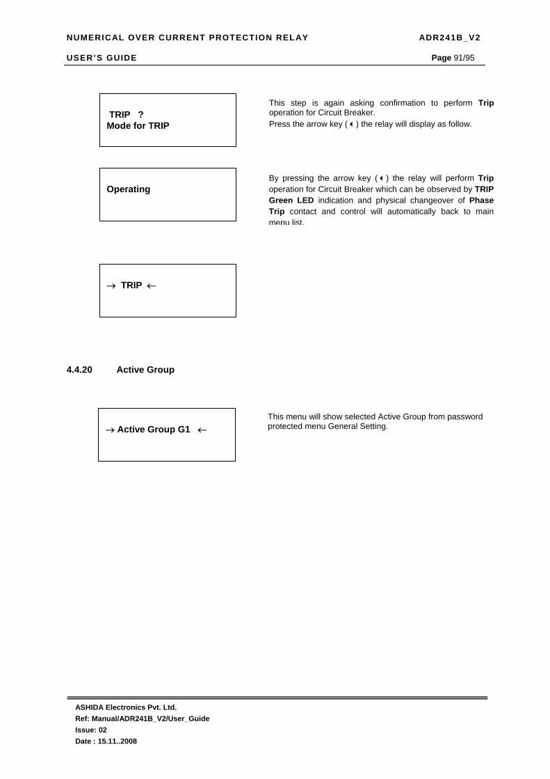
NUMERICAL OVER CURRENT PROTECTION RELAY ADR241B_V2 USER’S GUIDE
ASHIDA Electronics Pvt. Ltd. Ref: Manual/ADR241B_V2/User_Guide Issue: 02 Date : 15.11..2008
Page 91/95
4.4.20 Active Group
→ Active Group G1 ←
This menu will show selected Active Group from password protected menu General Setting.
TRIP ? Mode for TRIP
This step is again asking confirmation to perform Trip operation for Circuit Breaker. Press the arrow key ( ) the relay will display as follow.
Operating
By pressing the arrow key ( ) the relay will perform Trip operation for Circuit Breaker which can be observed by TRIP Green LED indication and physical changeover of Phase Trip contact and control will automatically back to main menu list.
→ TRIP ←

NUMERICAL OVER CURRENT PROTECTION RELAY ADR241B_V2 USER’S GUIDE
ASHIDA Electronics Pvt. Ltd. Ref: Manual/ADR241B_V2/User_Guide Issue: 02 Date : 15.11..2008
Page 92/95
4.4.21 DATE TIME SETTINGS
4.4.21.1 To Set – Date Time Setting
→ Date Time ←
Password protected menu to set the Date and Time . Press the arrow key ( ) the relay will display as follow.
Password = 001 Use INR/DEC
Enter the previously set password, By using the up arrow key or the down arrow key ( ). Note : Default password setting is ‘000’ Press the arrow key ( ) the relay will display as follow.
Time Set : 1 SET Hrs = 014 Range 0_23 Use Inr/Dec
By using the up arrow key ( ) or the down arrow key ( ) Hours can be set. The range is from 000-023 in steps of 001. Press the arrow key ( ) the relay will display as follow.
Time Set : 2 SET Mins = 005 Range 0_59 Use Inr/Dec
By using the up arrow key ( ) or the down arrow key ( ) Minutes can be set. The range is from 000-059 in steps of 001. Press the arrow key ( ) the relay will display as follow.
Time Set : 3 SET Sec = 035 Range 0_59 Use Inr/Dec
By using the up arrow key ( ) or the down arrow key ( ) Seconds can be set. The range is from 000-059 in steps of 001. Press the arrow key ( ) the relay will display as follow.
Date Set : 1 SET Date = 015 Range 1_31 Use Inr/Dec
By using the up arrow key ( ) or the down arrow key ( ) Date can be set. The range is from 001-031 in steps of 001. Press the arrow key ( ) the relay will display as follow.
Date Set : 2 SET Month = 011 Range 1-12 Use Inr/Dec
By using the up arrow key ( ) or the down arrow key ( ) Month can be set. The range is from 001-012 in steps of 001. Press the arrow key ( ) the relay will display as follow.

NUMERICAL OVER CURRENT PROTECTION RELAY ADR241B_V2 USER’S GUIDE
ASHIDA Electronics Pvt. Ltd. Ref: Manual/ADR241B_V2/User_Guide Issue: 02 Date : 15.11..2008
Page 93/95
4.4.21.2 To View – Date Time Setting
Date Set: 3 SET Year = 008 Range 00_99 Use Inr/Dec
By using the up arrow key ( ) or the down arrow key ( ) Year can be set. The range is from 000-099 in steps of 001. Press the arrow key ( ) the relay will display as follow.
Save Setting ? Mode For Save
To Save any changes. Press the arrow key ( ) the relay will save the change and the following message is display. Note : If changes made are not to be saved press LED Reset or leave key pad untouched for 100sec.
OK
This window will flash for moment The control will return to the main menu
→ Date Time ←
→ Date / Time ←
Press the arrow key ( ) the relay will display as follow.
Time : 14 : 05 : 35 Fri 15 / 11 / 08
Press the arrow key ( ) the relay will display the main menu.
→ Date / Time ←
NUMERICAL OVER CURRENT PROTECTION RELAY ADR241B_V2 USER’S GUIDE
ASHIDA Electronics Pvt. Ltd. Ref: Manual/ADR241B_V2/User_Guide Issue: 02 Date : 15.11..2008
Page 94/95
4.5 INPUT SIGNALS 4.5.1 Auxiliary Supply Input as per Back Terminals (BT) number. 4.5.2 CT Secondary Input as per Back Terminals (BT) number. 4.5.3 Status Input as per Back Terminals (BT) number. 4.5.4 Trip Circuit Supervision Input as per Back Terminals (BT) number.
4.6 OUTPUT SIGNALS
4.6.1 Trip Duty Trip contact as per Back Terminals (BT) number. 4.6.2 Trip Duty Programmable contact as per Back Terminals (BT) number.
4.6.3 Trip Duty BF(Local Breaker Back-up ) Protection contact as per Back Terminals (BT)
number. 4.6.4 Relay OK Healthy contact as per Back Terminals (BT) number. 4.6.5 Trip Duty Auto Recloser ‘Reclose’ contact as per Back Terminals (BT) number. 4.6.6 Trip Duty Auto Recloser ‘Lockout’ contact as per Back Terminals (BT) number. 4.6.7 Trip Duty Trip Circuit Supervision Contact as per Back Terminals (BT) number.

NUMERICAL OVER CURRENT PROTECTION RELAY ADR241B_V2 USER’S GUIDE
ASHIDA Electronics Pvt. Ltd. Ref: Manual/ADR241B_V2/User_Guide Issue: 02 Date : 15.11..2008
Page 95/95
4.7 Revision Note
Issue Date Description
01 06.05.2008 Original Version
02 15.11.2008 Relay / LED configuration setting menu changed

NUMERICAL OVER CURRENT PROTECTION RELAY ADR241B_V2 MENU CONTENT TABLE
ASHIDA Electronics Pvt. Ltd. Ref: Manual/ADR241B_V2/Menu Table Issue: 02 Date : 15.11.2008
Page 1/22
MENU CONTENT TABLE (For software V2.08)

NUMERICAL OVER CURRENT PROTECTION RELAY ADR241B_V2 MENU CONTENT TABLE
ASHIDA Electronics Pvt. Ltd. Ref: Manual/ADR241B_V2/Menu Table Issue: 02 Date : 15.11.2008
Page 2/22
CONTENTS
5 Menu Content Table 3
5.1 To View Measurement 3
5.2 To Set / View General Setting 4
5.3 To Set / View O/C – G1 Setting 5
5.4 To Set / View E/F – G1 Setting 6
5.5 To Set / View 3Io – G1 Setting 7
5.6 To Set / View NPS – G1 Setting 8
5.7 To Set / View O/C – G2 Setting 9
5.8 To Set / View E/F – G2 Setting 10
5.9 To Set / View 3Io – G2 Setting 11
5.10 To Set / View NPS – G2 Setting 12
5.11 To Set / View ARR Setting 13
5.12 To Set / View Relay/LED Setting 14
5.13 To View Fault 1 to Fault 20 Setting 15
5.14 To View Status Setting 19
5.15 To View Error Log Setting 19
5.16 To View Close Setting 19
5.17 To View Trip Setting 20
5.18 To View Active Group 20
5.19 To Set / View Date/Time Setting 21
5.20 Revision Note 22

NUMERICAL OVER CURRENT PROTECTION RELAY ADR241B_V2 MENU CONTENT TABLE
ASHIDA Electronics Pvt. Ltd. Ref: Manual/ADR241B_V2/Menu Table Issue: 02 Date : 15.11.2008
Page 3/22 5 MENU TABLE – SOFTWARE VERSION 2.08 5.1 To View – Measurement Setting
Secondary Current R=000.03 Y=000.02 B=000.04 3Io=000.03 CT Sec. Selected = 1A
Primary Current R=00000A Y=00000A B=00000A 3Io=00000A
I1=000.00 I2=000.01 EF=000.01
Secondary Current R = 000.00 Y = 000.00 B = 000.00 3Io=000.03 CT Sec. Selected = 1A
→ Measurement ←
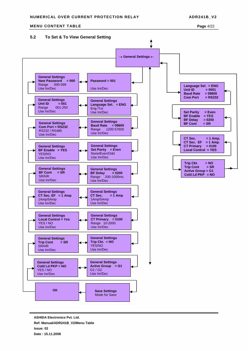
NUMERICAL OVER CURRENT PROTECTION RELAY ADR241B_V2 MENU CONTENT TABLE
ASHIDA Electronics Pvt. Ltd. Ref: Manual/ADR241B_V2/Menu Table Issue: 02 Date : 15.11.2008
Page 4/22 5.2 To Set & To View General Setting
General Settings BF Enable = YES YES/NO Use Inr/Dec
General Settings New Password = 000Range 000-099 Use Inr/Dec
Password = 001 Use Inr/Dec
General Settings Baud Rate = 09600 Range 1200-57600 Use Inr/Dec
General Settings BF Delay = 0200 Range 200-1000ms Use Inr/Dec
General Settings Unit ID = 001 Range 001-250 Use Inr/Dec
General Settings Trip Cont = SR SR/HR Use Inr/Dec
→ General Settings ←
OK
General Settings BF Cont = SR SR/HR Use Inr/Dec
Save Settings Mode for Save
General Settings Active Group = G1 G1 / G2 Use Inr/Dec
General Settings Set Parity = Even None/Even/Odd Use Inr/Dec
General Settings CT Sec. EF = 1 Amp 1Amp/5Amp Use Inr/Dec
General Settings Cold Ld PKP = NO YES / NO Use Inr/Dec
General Settings Com Port = RS232 RS232 / RS485 Use Inr/Dec
General Settings CT Sec. = 1 Amp 1Amp/5Amp Use Inr/Dec
General Settings Trip Ckt. = NO YES/NO Use Inr/Dec
Language Sel. = ENG Unit ID = 0001 Baud Rate = 09600 Com Port = RS232
Set Parity = Even BF Enable = YES BF Delay = 0200 BF Cont = SR
CT Sec. = 1 Amp.CT Sec. EF = 1 Amp. CT Primary = 0100 Local Control = YES
General Settings Language Sel. = ENG Eng /Tur Use Inr/Dec
General Settings CT Primary = 0100 Range 10-2000 Use Inr/Dec
General Settings Local Control = Yes YES / NO Use Inr/Dec
Trip Ckt. = NO Trip Cont = SR Active Group = G1 Cold Ld PKP = NO

NUMERICAL OVER CURRENT PROTECTION RELAY ADR241B_V2 MENU CONTENT TABLE
ASHIDA Electronics Pvt. Ltd. Ref: Manual/ADR241B_V2/Menu Table Issue: 02 Date : 15.11.2008
Page 5/22 5.3 To Set & To View OC – G1 Setting
OC – G1 Settings IP> Enable = YES YES/NO Use Inr/Dec
Password = 0000 Use Inr/Dec
OC – G1 Settings IP> = 0020 Range 10%-200% Use Inr/Dec
→ OC – G1 Settings ←
IP>= ON IP> = 0020 IP>TMS = 01.00 IP>Curve = 0001 IP>C6 Delay = 00.05
IP>>= ON IP>>= 0020 IP>>TMS = 01.00IP>>Curve = 0001 IP>>C6 Delay = 00.05
IP>>> = ON IP>>> = 0200 IP>>> Delay = 00.05
OC – G1Settings IP> TMS = 01.00 Range x0.02-x1.00 Use Inr/Dec
OC – G1 Settings IP>> Enable = YES YES/NO Use Inr/Dec
OC – G1 Settings IP> C6 Delay = 00.05 Range 00.00-99.9S Use Inr/Dec
OC – G1 Settings IP> Curve = 0001 Range C1-C6 Use Inr/Dec
OC – G1 Settings IP>> Curve = 0001 Range C1-C6 Use Inr/Dec
OC – G1 Settings IP>> TMS = 01.00 Range x0.02-x1.00 Use Inr/Dec
OC – G1 Settings IP>> = 0020 Range 10%-200% Use Inr/Dec
OC – G1 Settings IP>>> = 0200 Range 50%- 2000% Use Inr/Dec
OC – G1 Settings IP>>> Enable = YES YES/NO Use Inr/Dec
OC – G1 Settings IP>> C6 Delay = 00.05 Range 00.00-99.9S Use Inr/Dec
OC – G1 Settings IP>>> Delay = 00.05 Range 00.00-02.00S Use Inr/Dec
Save Settings Mode for Save
OK

NUMERICAL OVER CURRENT PROTECTION RELAY ADR241B_V2 MENU CONTENT TABLE
ASHIDA Electronics Pvt. Ltd. Ref: Manual/ADR241B_V2/Menu Table Issue: 02 Date : 15.11.2008
Page 6/22 5.4 To Set & To View EF – G1 Setting
Password = 0000 Use Inr/Dec
→ EF –G1 Settings ←
EF – G1 Settings IE> = 0020 Range 10%-200% Use Inr/Dec
EF – G1 Settings IE> Enable = YES YES/NO Use Inr/Dec
EF – G1 Settings IE> C6 Delay = 00.05 Range 00.00-99.9S Use Inr/Dec
EF – G1 Settings IE> Curve = 0001 Range C1-C6 Use Inr/Dec
EF – G1 Settings IE> TMS = 01.00 Range x0.02-x1.00 Use Inr/Dec
EF – G1 Settings IE>> TMS = 01.00 Range x0.02-x1.00 Use Inr/Dec
EF – G1 Settings IE>> = 0020 Range 10%-200% Use Inr/Dec
EF – G1 Settings IE>> Enable = YES YES/NO Use Inr/Dec
EF – G1 Settings IE>>> Enable = YES YES/NO Use Inr/Dec
EF – G1 Settings IE>> C6 Delay = 00.05 Range 00.00-99.9S Use Inr/Dec
EF – G1 Settings IE>> Curve = 0001 Range C1-C6 Use Inr/Dec
Save Settings Mode for Save
EF – G1 Settings IE>>> Delay = 00.05 Range 00.00-2.00S Use Inr/Dec
EF – G1 Settings IE>>> = 0200 Range 50%- 2000% Use Inr/Dec
IE>= ON IE> = 0020 IE>TMS = 01.00 IE>Curve = 0001 IE>C6 Delay = 00.05
IE>>= ON IE>> = 0020 IE>>TMS = 01.00 IE>>Curve = 0001 IE>>C6 Delay = 00.05
IE>>> = ON IE>>> = 200 IE>>> Delay = 00.05
OK

NUMERICAL OVER CURRENT PROTECTION RELAY ADR241B_V2 MENU CONTENT TABLE
ASHIDA Electronics Pvt. Ltd. Ref: Manual/ADR241B_V2/Menu Table Issue: 02 Date : 15.11.2008
Page 7/22 5.5 To Set & To View 3Io – G1 Setting
Password = 0000 Use Inr/Dec
→3Io – G1 Settings ←
3Io – G1 Settings 3Io> = 0020 Range 10%-200% Use Inr/Dec
3Io – G1 Settings 3Io > Enable = YES YES/NO Use Inr/Dec
3Io – G1 Settings 3Io> C6 Delay = 00.05 Range 00.00-99.90S Use Inr/Dec
3Io – G1 Settings 3Io> Curve = 0001 Range C1-C6 Use Inr/Dec
3Io – G1 Settings 3Io> TMS = 01.00 Range x0.02-x1.00 Use Inr/Dec
3Io – G1 Settings 3Io>> TMS = 01.00 Range x0.02-x1.00 Use Inr/Dec
3Io – G1 Settings 3Io>> = 0020 Range 10%-200% Use Inr/Dec
3Io – G1 Settings 3Io>> Enable = YES YES/NO Use Inr/Dec
3Io – G1 Settings 3Io>>> Enable = YES YES/NO Use Inr/Dec
3Io – G1 Settings 3Io>> C6 Delay = 00.05 Range 00.00-99.90S Use Inr/Dec
3Io – G1 Settings 3Io>> Curve = 0001 Range C1-C6 Use Inr/Dec
Save Settings Mode for Save
3Io – G1 Settings 3Io>>> Delay = 00.05 Range 00.00-2.00S Use Inr/Dec
3Io – G1 Settings 3Io>>> = 0200 Range 50%- 2000% Use Inr/Dec
3Io>= ON 3Io> = 0020 3Io>TMS = 01.00 3Io>Curve = 0001 3Io>C6 Delay = 00.05
3Io>>= ON 3Io>> = 00203Io>>TMS = 01.003Io>>Curve = 0001 3Io>>C6 Delay = 00.05
3Io>>>= ON 3Io>>> = 0200 3Io>>> C6 Delay = 00.05
OK

NUMERICAL OVER CURRENT PROTECTION RELAY ADR241B_V2 MENU CONTENT TABLE
ASHIDA Electronics Pvt. Ltd. Ref: Manual/ADR241B_V2/Menu Table Issue: 02 Date : 15.11.2008
Page 8/22 5.6 To Set & To View NPS – G1 Setting
Password = 0000 Use Inr/Dec
→ NPS – G1 Settings ←
NPS – G1 Settings I2>> = 0020 Range 10%-200% Use Inr/Dec
NPS – G1 Settings I2>>Enable = YES YES/NO Use Inr/Dec
NPS – G1 Settings I2>>C6 Delay = 00.05 Range 00.00-99.90S Use Inr/Dec
NPS – G1 Settings I2>>Curve = 0001 Range C1-C6 Use Inr/Dec
NPS – G1 Settings I2>>TMS = 01.00 Range x0.02-x1.00 Use Inr/Dec
NPS – G1 Settings I2>>> Delay = 00.05 Range 00.00-2.00S Use Inr/Dec
NPS – G1 Settings I2>>> = 0020 Range 50%-1500% Use Inr/Dec
NPS – G1 Settings I2>>> Enable = YES YES/NO Use Inr/Dec
Save Settings Mode for Save
I2>>= ON I2>> = 0020 I2>>TMS = 01.00 I2>>Curve = 0001 I2>>C6 Delay = 00.05
I2>>>= ON I2>>> = 0200 I2>>>Curve = 00.05
OK

NUMERICAL OVER CURRENT PROTECTION RELAY ADR241B_V2 MENU CONTENT TABLE
ASHIDA Electronics Pvt. Ltd. Ref: Manual/ADR241B_V2/Menu Table Issue: 02 Date : 15.11.2008
Page 9/22 5.7 To Set & To View OC – G2 Setting
OC – G2 Settings IP> Enable = YES YES/NO Use Inr/Dec
Password = 0000 Use Inr/Dec
OC – G2 Settings IP> = 0020 Range 10%-200% Use Inr/Dec
→ OC – G2 Settings ←
IP>= ON IP> = 0020 IP>TMS = 01.00 IP>Curve = 0001 IP>C6 Delay = 00.05
IP>>= ON IP>>= 0020 IP>>TMS = 01.00IP>>Curve = 0001 IP>>C6 Delay = 00.05
IP>>>= ON IP>>> = 0200 IP>>> Delay = 00.05
OC – G2 Settings IP> TMS = 01.00 Range x0.02-x1.00 Use Inr/Dec
OC – G2 Settings IP>> Enable = YES YES/NO Use Inr/Dec
OC – G2 Settings IP> C6 Delay = 00.05 Range 00.00-99.9S Use Inr/Dec
OC – G2 Settings IP> Curve = 0001 Range C1-C6 Use Inr/Dec
OC – G2 Settings IP>> Curve = 0001 Range C1-C6 Use Inr/Dec
OC – G2 Settings IP>> TMS = 01.00 Range x0.02-x1.00 Use Inr/Dec
OC – G2 Settings IP>> = 0020 Range 10%-200% Use Inr/Dec
OC – G2 Settings IP>>> = 0200 Range 50%- 2000% Use Inr/Dec
OC – G2 Settings IP>>> Enable = YES YES/NO Use Inr/Dec
OC – G2 Settings IP>> C6 Delay = 00.05 Range 00.00-99.9S Use Inr/Dec
OC – G2 Settings IP>>> Delay = 00.05 Range 00.00-02.00S Use Inr/Dec
Save Settings Mode for Save
OK

NUMERICAL OVER CURRENT PROTECTION RELAY ADR241B_V2 MENU CONTENT TABLE
ASHIDA Electronics Pvt. Ltd. Ref: Manual/ADR241B_V2/Menu Table Issue: 02 Date : 15.11.2008
Page 10/22 5.8 To Set & To View EF – G2 Setting
Password = 0000 Use Inr/Dec
→ EF – G2 Settings ←
EF – G2 Settings IE> = 0020 Range 10%-200% Use Inr/Dec
EF – G2 Settings IE> Enable = YES YES/NO Use Inr/Dec
EF – G2 Settings IE> C6 Delay = 00.05 Range 00.00-99.9S Use Inr/Dec
EF – G2 Settings IE> Curve = 0001 Range C1-C6 Use Inr/Dec
EF – G2 Settings IE> TMS = 01.00 Range x0.02-x1.00 Use Inr/Dec
EF – G2 Settings IE>> TMS = 01.00 Range x0.02-x1.00 Use Inr/Dec
EF – G2 Settings IE>> = 0020 Range 10%-200% Use Inr/Dec
EF – G2 Settings IE>> Enable = YES YES/NO Use Inr/Dec
EF – G2 Settings IE>>> Enable = YES YES/NO Use Inr/Dec
EF – G2 Settings IE>> C6 Delay = 00.05 Range 00.00-99.9S Use Inr/Dec
EF – G2 Settings IE>> Curve = 0001 Range C1-C6 Use Inr/Dec
Save Settings Mode for Save
EF – G2 Settings IE>>> Delay = 00.05 Range 00.00-2.00S Use Inr/Dec
EF – G2 Settings IE>>> = 0200 Range 50%- 2000% Use Inr/Dec
IE>= ON IE> = 0020 IE>TMS = 01.00 IE>Curve = 0001 IE>C6 Delay = 00.05
IE>>= ON IE>> = 0020 IE>>TMS = 01.00 IE>>Curve = 0001 IE>>C6 Delay = 00.05
IE>>>= ON IE>>> = 200 IE>>> Delay = 00.05
OK

NUMERICAL OVER CURRENT PROTECTION RELAY ADR241B_V2 MENU CONTENT TABLE
ASHIDA Electronics Pvt. Ltd. Ref: Manual/ADR241B_V2/Menu Table Issue: 02 Date : 15.11.2008
Page 11/22 5.9 To Set & To View 3Io – G2 Setting
Password = 0000 Use Inr/Dec
→3Io – G2 Settings ←
3Io – G2 Settings 3Io> = 0020 Range 10%-200% Use Inr/Dec
3Io – G2 Settings 3Io > Enable = YES YES/NO Use Inr/Dec
3Io – G2 Settings 3Io> C6 Delay = 00.05 Range 00.00-99.90S Use Inr/Dec
3Io – G2 Settings 3Io> Curve = 0001 Range C1-C6 Use Inr/Dec
3Io – G2 Settings 3Io> TMS = 01.00 Range x0.02-x1.00 Use Inr/Dec
3Io – G2 Settings 3Io>> TMS = 01.00 Range x0.02-x1.00 Use Inr/Dec
3Io – G2 Settings 3Io>> = 0020 Range 10%-200% Use Inr/Dec
3Io – G2 Settings 3Io>> Enable = YES YES/NO Use Inr/Dec
3Io – G2 Settings 3Io>>> Enable = YES YES/NO Use Inr/Dec
3Io – G2 Settings 3Io>> C6 Delay = 00.05 Range 00.00-99.90S Use Inr/Dec
3Io – G2 Settings 3Io>> Curve = 0001 Range C1-C6 Use Inr/Dec
Save Settings Mode for Save
3Io – G2 Settings 3Io>>> Delay = 00.05 Range 00.00-2.00S Use Inr/Dec
3Io – G2 Settings 3Io>>> = 0200 Range 50%- 2000% Use Inr/Dec
3Io>= ON 3Io> = 0020 3Io>TMS = 01.00 3Io>Curve = 0001 3Io>C6 Delay = 00.05
3Io>>= ON 3Io>> = 00203Io>>TMS = 01.003Io>>Curve = 0001 3Io>>C6 Delay = 00.05
3Io>>>= ON 3Io>>> = 0200 3Io>>> C6 Delay = 00.05
OK

NUMERICAL OVER CURRENT PROTECTION RELAY ADR241B_V2 MENU CONTENT TABLE
ASHIDA Electronics Pvt. Ltd. Ref: Manual/ADR241B_V2/Menu Table Issue: 02 Date : 15.11.2008
Page 12/22 5.10 To Set & To View NPS – G2 Setting
Password = 0000 Use Inr/Dec
→ NPS – G2 Settings ←
NPS – G2 Settings I2>> = 0020 Range 10%-200% Use Inr/Dec
NPS – G2 Settings I2>>Enable = YES YES/NO Use Inr/Dec
NPS – G2 Settings I2>>C6 Delay = 00.05 Range 00.00-99.90S Use Inr/Dec
NPS – G2 Settings I2>>Curve = 0001 Range C1-C6 Use Inr/Dec
NPS – G2 Settings I2>>TMS = 01.00 Range x0.02-x1.00 Use Inr/Dec
NPS – G2 Settings I2>>> Delay = 00.05 Range 00.00-2.00S Use Inr/Dec
NPS – G2 Settings I2>>> = 0200 Range 50%-1500% Use Inr/Dec
NPS – G2 Settings I2>>> Enable = YES YES/NO Use Inr/Dec
Save Settings Mode for Save
I2>>= ON I2>> = 0020 I2>>TMS = 01.00 I2>>Curve = 0001 I2>>C6 Delay = 00.05
I2>>>= ON I2>>> = 0200 I2>>>Curve = 00.05
OK

NUMERICAL OVER CURRENT PROTECTION RELAY ADR241B_V2 MENU CONTENT TABLE
ASHIDA Electronics Pvt. Ltd. Ref: Manual/ADR241B_V2/Menu Table Issue: 02 Date : 15.11.2008
Page 13/22 5.11 To Set & To View ARR Setting
→ ARR Settings ←
ARR = ON N SHOT = 004 DT1 = 010.00 DT2 = 005.10
DT3 = 010.00 DT4 = 005.10 Reclaim Time = 0200.0
DT4 = 1.00 Range 0.10-180.00S Use Inr/Dec
Password = 001 Use Inr/Dec
N SHOT = 000 Range 00-04 Use Inr/Dec
DT1 = 1.00 Range 0.10-180.00S Use Inr/Dec
AARR Enable = YES
YES / NO Use Inr / Dec
Save Settings?
Mode for Save
RECLAIM TIME Reclaim Time = 0100.0 Range 1.0-200.0S Use Inr/Dec
DT3 = 1.00 Range 0.10-180.00S Use Inr/Dec
DT2 = 1.00 Range 0.10-180.00S Use Inr/Dec
OK

NUMERICAL OVER CURRENT PROTECTION RELAY ADR241B_V2 MENU CONTENT TABLE
ASHIDA Electronics Pvt. Ltd. Ref: Manual/ADR241B_V2/Menu Table Issue: 02 Date : 15.11.2008
Page 14/22 5.12 To Set & To View Relay/LED Setting
→ Relay/LED Config ←
RL1 A = 0000 RL1 B = 0000 RL2 A = 0000 RL2 B = 0000
RL3 A = 0000 RL3 B = 0000 RL4 A = 0000 RL4 B = 0000
RL5 A = 0000 RL5 B = 0000 L5 Green A = 0000 L5 Green B = 0000
RL4 A = 0000 Use Inr/Dec
RL3 B = 0000 Use Inr/Dec
RL3 A = 0000 Use Inr/Dec
RL5 B = 0000 Use Inr/Dec
RL5 A = 0000 Use Inr/Dec
RL4 B = 0000 Use Inr/Dec
L5 Red A = 0000 Use Inr/Dec
L5 Green B = 0000 Use Inr/Dec
L5 Green A = 0000 Use Inr/Dec
L6 Green B = 0000 Use Inr/Dec
L6 Green A = 0000 Use Inr/Dec
L5 Red B = 0000 Use Inr/Dec
L7 Green A = 0000 Use Inr/Dec
L6 Red B = 0000 Use Inr/Dec
L6 Red A = 0000 Use Inr/Dec
L5 Red A = 0000 L5 Red B = 0000 L6 Green A = 0000 L6 Green B = 0000
L6 Red A = 0000 L6 Red B = 0000 L7 Green A = 0000 L7 Green B = 0000
RL2 A = 0000 Use Inr/Dec
RL2 B = 0000 Use Inr/Dec
RL1 A = 0000 Use Inr/Dec
Password = 001 Use Inr/Dec
L7 Red A = 0000 L7 Red B = 0000 S1 = 0000 S2 = 0000
L7 Red B = 0000 Use Inr/Dec
L7 Red A = 0000 Use Inr/Dec
L7 Green B = 0000 Use Inr/Dec
S3 = 0000 S4 = 0000 S5 = 0000
RL1 B = 0000 Use Inr/Dec
S3 = 0000 Use Inr/Dec
S2 = 0000 Use Inr/Dec
S1 = 0000 Use Inr/Dec
Save Settings? Mode for Save
S5 = 0000 Use Inr/Dec
S4 = 0000 Use Inr/Dec
OK

NUMERICAL OVER CURRENT PROTECTION RELAY ADR241B_V2 MENU CONTENT TABLE
ASHIDA Electronics Pvt. Ltd. Ref: Manual/ADR241B_V2/Menu Table Issue: 02 Date : 15.11.2008
Page 15/22 5.13 To View – Faults
→ Fault 1 ←
I> : R I>> : I>>> : TC : 0073
R=100.01 Y=000.01 B=000.10 3Io=000.10 Date : 13/10//08 Time : 12:50:15.500
Primary Current R=01000A Y=00000A B=00000A 3Io=00230A
EF=000.02 I2=000.76
→ Fault 2 ←
I> : R I>> : I>>> : TC : 0073
R=100.01 Y=000.01 B=000.10 3Io=000.10 Date : 13/10//08 Time : 12:50:15.500
Primary Current R=01000A Y=00000A B=00000A 3Io=00230A
EF=000.02 I2=000.76
→ Fault 3 ←
I> : R I>> : I>>> : TC : 0073
R=100.01 Y=000.01 B=000.10 3Io=000.10 Date : 13/10//08 Time : 12:50:15.500
Primary Current R=01000A Y=00000A B=00000A 3Io=00230A
EF=000.02 I2=000.76
→ Fault 4 ←
I> : R I>> : I>>> : TC : 0073
R=100.01 Y=000.01 B=000.10 3Io=000.10 Date : 13/10//08 Time : 12:50:15.500
Primary Current R=01000A Y=00000A B=00000A 3Io=00230A
EF=000.02 I2=000.76
→ Fault 5 ←
I> : R I>> : I>>> : TC : 0073
R=100.01 Y=000.01 B=000.10 3Io=000.10 Date : 13/10//08 Time : 12:50:15.500
Primary Current R=01000A Y=00000A B=00000A 3Io=00230A
EF=000.02 I2=000.76

NUMERICAL OVER CURRENT PROTECTION RELAY ADR241B_V2 MENU CONTENT TABLE
ASHIDA Electronics Pvt. Ltd. Ref: Manual/ADR241B_V2/Menu Table Issue: 02 Date : 15.11.2008
Page 16/22
→ Fault 6 ←
I> : R I>> : I>>> : TC : 0073
R=100.01 Y=000.01 B=000.10 3Io=000.10 Date : 13/10//08 Time : 12:50:15.500
Primary Current R=01000A Y=00000A B=00000A 3Io=00230A
EF=000.02 I2=000.76
→ Fault 7 ←
I> : R I>> : I>>> : TC : 0073
R=100.01 Y=000.01 B=000.10 3Io=000.10 Date : 13/10//08 Time : 12:50:15.500
Primary Current R=01000A Y=00000A B=00000A 3Io=00230A
EF=000.02 I2=000.76
→ Fault 8 ←
I> : R I>> : I>>> : TC : 0073
R=100.01 Y=000.01 B=000.10 3Io=000.10 Date : 13/10//08 Time : 12:50:15.500
Primary Current R=01000A Y=00000A B=00000A 3Io=00230A
EF=000.02 I2=000.76
→ Fault 9 ←
I> : R I>> : I>>> : TC : 0073
R=100.01 Y=000.01 B=000.10 3Io=000.10 Date : 13/10//08 Time : 12:50:15.500
Primary Current R=01000A Y=00000A B=00000A 3Io=00230A
EF=000.02 I2=000.76
→ Fault 10 ←
I> : R I>> : I>>> : TC : 0073
R=100.01 Y=000.01 B=000.10 3Io=000.10 Date : 13/10//08 Time : 12:50:15.500
Primary Current R=01000A Y=00000A B=00000A 3Io=00230A
EF=000.02 I2=000.76
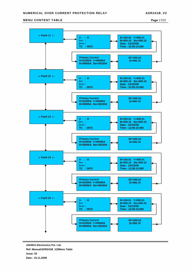
NUMERICAL OVER CURRENT PROTECTION RELAY ADR241B_V2 MENU CONTENT TABLE
ASHIDA Electronics Pvt. Ltd. Ref: Manual/ADR241B_V2/Menu Table Issue: 02 Date : 15.11.2008
Page 17/22
→ Fault 11 ←
I> : R I>> : I>>> : TC : 0073
R=100.01 Y=000.01 B=000.10 3Io=000.10 Date : 13/10//08 Time : 12:50:15.500
Primary Current R=01000A Y=00000A B=00000A 3Io=00230A
EF=000.02 I2=000.76
→ Fault 12 ←
I> : R I>> : I>>> : TC : 0073
R=100.01 Y=000.01 B=000.10 3Io=000.10 Date : 13/10//08 Time : 12:50:15.500
Primary Current R=01000A Y=00000A B=00000A 3Io=00230A
EF=000.02 I2=000.76
→ Fault 13 ←
I> : R I>> : I>>> : TC : 0073
R=100.01 Y=000.01 B=000.10 3Io=000.10 Date : 13/10//08 Time : 12:50:15.500
Primary Current R=01000A Y=00000A B=00000A 3Io=00230A
EF=000.02 I2=000.76
→ Fault 14 ←
I> : R I>> : I>>> : TC : 0073
R=100.01 Y=000.01 B=000.10 3Io=000.10 Date : 13/10//08 Time : 12:50:15.500
Primary Current R=01000A Y=00000A B=00000A 3Io=00230A
EF=000.02 I2=000.76
→ Fault 15 ←
I> : R I>> : I>>> : TC : 0073
R=100.01 Y=000.01 B=000.10 3Io=000.10 Date : 13/10//08 Time : 12:50:15.500
Primary Current R=01000A Y=00000A B=00000A 3Io=00230A
EF=000.02 I2=000.76

NUMERICAL OVER CURRENT PROTECTION RELAY ADR241B_V2 MENU CONTENT TABLE
ASHIDA Electronics Pvt. Ltd. Ref: Manual/ADR241B_V2/Menu Table Issue: 02 Date : 15.11.2008
Page 18/22
→ Fault 16 ←
I> : R I>> : I>>> : TC : 0073
R=100.01 Y=000.01 B=000.10 3Io=000.10 Date : 13/10//08 Time : 12:50:15.500
Primary Current R=01000A Y=00000A B=00000A 3Io=00230A
EF=000.02 I2=000.76
→ Fault 17 ←
I> : R I>> : I>>> : TC : 0073
R=100.01 Y=000.01 B=000.10 3Io=000.10 Date : 13/10//08 Time : 12:50:15.500
Primary Current R=01000A Y=00000A B=00000A 3Io=00230A
EF=000.02 I2=000.76
→ Fault 18 ←
I> : R I>> : I>>> : TC : 0073
R=100.01 Y=000.01 B=000.10 3Io=000.10 Date : 13/10//08 Time : 12:50:15.500
Primary Current R=01000A Y=00000A B=00000A 3Io=00230A
EF=000.02 I2=000.76
→ Fault 19 ←
I> : R I>> : I>>> : TC : 0073
R=100.01 Y=000.01 B=000.10 3Io=000.10 Date : 13/10//08 Time : 12:50:15.500
Primary Current R=01000A Y=00000A B=00000A 3Io=00230A
EF=000.02 I2=000.76
→ Fault 20 ←
I> : R I>> : I>>> : TC : 0073
R=100.01 Y=000.01 B=000.10 3Io=000.10 Date : 13/10//08 Time : 12:50:15.500
Primary Current R=01000A Y=00000A B=00000A 3Io=00230A
EF=000.02 I2=000.76

NUMERICAL OVER CURRENT PROTECTION RELAY ADR241B_V2 MENU CONTENT TABLE
ASHIDA Electronics Pvt. Ltd. Ref: Manual/ADR241B_V2/Menu Table Issue: 02 Date : 15.11.2008
Page 19/22 5.14 To View – Status Setting 5.15 To View Error Log Setting 5.16 To View Close Setting
→ Status ←
S1 : OFF S2 : OFF S3 : OFF S4 : OFF S5 : OFF T1 : OFF T2 : OFF
→ Error Log ←
Error Code : 0000 Trip Ckt. Test = NO T1: OFF T2:OFF Trip Ckt: Healthy
→ CLOSE ←
Operating
CLOSE ? Mode For CLOSE
Password = 001 Use INR/DEC

NUMERICAL OVER CURRENT PROTECTION RELAY ADR241B_V2 MENU CONTENT TABLE
ASHIDA Electronics Pvt. Ltd. Ref: Manual/ADR241B_V2/Menu Table Issue: 02 Date : 15.11.2008
Page 20/22 5.17 To View Trip Setting 5.18 To View Active Group
→ Active Group ←
→ TRIP ←
Operating
TRIP ? Mode For Trip
Password = 001 Use INR/DEC

NUMERICAL OVER CURRENT PROTECTION RELAY ADR241B_V2 MENU CONTENT TABLE
ASHIDA Electronics Pvt. Ltd. Ref: Manual/ADR241B_V2/Menu Table Issue: 02 Date : 15.11.2008
Page 21/22
5.19 To Adjust & To View Date/Time Setting
Password = 001 Use INR/DEC
Time Set : 2 SET Mins = 005 Range 0-59 Use Inr/ Drc
Time Set : 3 SET Sec = 035 Range 0-59 Use Inr/ Drc
Time Set : 1 SET Hrs = 014 Range 0-23 Use Inr/ Drc
→ Date/Time ←
OK
Time : 04:32:20 Wed : 26/06/08
Save Settings? Mode for Save
Date Set : 3 SET Year = 008 Range 00-99 Use Inr/Dec
Date Set : 2 SET Month : 011 Range 1-12 Use Inr/Dec
Date Set : 1 SET Date = 015 Range 1-31 Use Inr/Dec

NUMERICAL OVER CURRENT PROTECTION RELAY ADR241B_V2 MENU CONTENT TABLE
ASHIDA Electronics Pvt. Ltd. Ref: Manual/ADR241B_V2/Menu Table Issue: 02 Date : 15.11.2008
Page 22/22
5.20 Revision Note
Issue Date Description
01 06.05.2008 Original Version
02 15.11.2008 Relay LEDs Configuration modified

NUMERICAL OVER CURRENT PROTECTION RELAY ADR241B_V2 TECHNICAL SPECIFICATION
ASHIDA Electronics Pvt. Ltd Ref: Manual/ADR241B_V2/Technical_specification Issue: 02 Date : 15.11.2008
Page 1/10
TECHNICAL SPECIFICATION

NUMERICAL OVER CURRENT PROTECTION RELAY ADR241B_V2 TECHNICAL SPECIFICATION
ASHIDA Electronics Pvt. Ltd Ref: Manual/ADR241B_V2/Technical_specification Issue: 02 Date : 15.11.2008
Page 2/10
CONTENTS
6.1 Protection Features 3
6.2 Relay Design Features 3
6.3 Block Diagram 4
6.4 Description 5
6.5 Technical Specification 6
6.6 Revision Note 10

NUMERICAL OVER CURRENT PROTECTION RELAY ADR241B_V2 TECHNICAL SPECIFICATION
ASHIDA Electronics Pvt. Ltd Ref: Manual/ADR241B_V2/Technical_specification Issue: 02 Date : 15.11.2008
Page 3/10
6.1 Protection Features:
4 Element (3 Phase + EF) Over current IDMT/DMT with Instantaneous Element
(50/51 and 50N/51N).
Programmable (Non- Volatile) Setting By local keys as well as remote setting by
communication port
Selection of Curve: Five selectable curve (Normal Inverse 1 (C1), Normal Inverse 2, (C2)
Very inverse (C3), Extremely inverse (C4), Long time inverse (C5)) and Define Time (C6)
Instantaneous Over-Current Protection with adjustable timer.
Breaker Failure detection ( 50 BF)
In-built CB Trip Circuit Supervision function during pre closing and post closing of CB.
Negative sequence over current (46).
Auto Recloser Relay ARR ( 79 ) 6.2 Relay Design Features:
Large 20x4 LCD display for Parameter and setting display
Disturbance Recorder. Up 3 sec of actual waveform of current along with logical and
physical status, are captured & saved in the built-in memory with date time stamping, for
analyzing fault condition & fault location.
Fully communicable with IEC standard open protocol.
Separate Communication Port for SCADA (RS485) as well as Local testing (RS232C)
Very low burden on CT (less than 0.5VA)
Online display of CB status and other digital and logical status.
Continuous monitoring of module’s internal hardware and alarm generation in case of
failure of any critical components.
Facility to synchronised Relay time with external GPS network
5 Digital Output contacts for local alarm as well as tele-signalling
5 Optically isolated digital status input for monitoring of status and avoid used of external
relay logic
2 dedicated status input for Trip Circuit Monitoring
100 nos of event memory, event such CB close, Trip, digital status change, relay pkp etc.
All events are with date and time stamped up to 1ms.
20 nos of Fault data stored with keypad interface and time stamping.
2 no.s of setting group available for each protection function.


NUMERICAL OVER CURRENT PROTECTION RELAY ADR241B_V2 TECHNICAL SPECIFICATION
ASHIDA Electronics Pvt. Ltd Ref: Manual/ADR241B_V2/Technical_specification Issue: 02 Date : 15.11.2008
Page 5/10
6.4 Description:
ADR241B is second generation Numerical 3 OC + 1EF Over Current Relay. It consist all the
necessary protection and monitoring functions required for Normal feeder it consist of
1. High Speed Digital DSP Controller
2. Analog Measuring Module
3. Power supply Module
4. Digital Input output module.
The High speed Digital Signal Controller continuously monitors line phase current and E/F
current. Along with different status input, through CTs, and optical isolated status
connections. The high-speed micro-controller samples these current signals through a A/D converter. The Digital Signal performs powerful Numerical Algorithms to find out RMS of
fundamental & harmonic contents of the current. All measurement is tuned to fundamental
frequency i.e 50Hz, thus relay remain stable during distorted waveform generated
electronics loco-motive. All these measure values are then used for different protection
function such as IDMT Over current protection, Instantaneous Over current protection, E/F
protection etc. These measured values are also displayed on large 20 x 4 LCD display for
metering purpose. The DSC also monitors different digital input through optical isolator and
perform some monitoring function such trip circuit supervision, and control potential free
contact for control CB and generate ALARM and Tele-signalling.
The power supply module is basically DC – DC converted designed using modern PWM
based Switching mode technique to convert 110Vdc station battery supply to the 12V and
24Vdc low voltage supply for relay electronics and control circuit. It also provides necessary
isolation from station battery. There are two type of power supply modules are available 1)
having range of 77Vdc – 250Vdc. Covering requirement of 110Vdc and 220Vdc station
battery system 2) having range of 18Vdc to 52Vdc covering 24Vdc, 30Vdc, 48Vdc station
battery requirement.
The relay is having total 8 nos of dual LED of high intensity for easy identification of type of
fault for easy user interface. LEDs L5, L6 and L7 and Relay R1 to R5, digital status input and
controlled output are fully programmable via key pad interface.

NUMERICAL OVER CURRENT PROTECTION RELAY ADR241B_V2 TECHNICAL SPECIFICATION
ASHIDA Electronics Pvt. Ltd Ref: Manual/ADR241B_V2/Technical_specification Issue: 02 Date : 15.11.2008
Page 6/10
6.5 Technical Specifications
General specifications Sr. No. Specification Particulars
I. Current Input : Suitable for CT secondary 5 Amp. or 1 Amp. site selectable II. Aux. Supply : 18 – 125 VDC/AC.
III. VA burden on CT : Less than 0.2VA IV. VA burden on Aux. : Less than 10 Watts V. Operating Temp. range : -10 deg. To + 65 deg. VI. Continuous Current carrying
capacity : 2 x of rated
VII. Pick up : Within 1.1 times of set value VIII. Reset Value : 95% to 90% of pick up.
IX. Output Contact : 1 for Phase Trip : 1 for EF/NPS/3Io Trip : 1 for Reclose : 1 for BF : 1 for RL-OK. : 1 for R-LOCK : 5 for General Programmable
X. Contact Rating : Continuous : 5A : Make & carry for 0.5 sec : 30A : Make carry for 3 sec : 15A
XI. Opto Isolated input : 1 for CB NO : 1 for CB NC : 5 for General Programmable
XII. Thermal With stand for CT : 20 x of rated for 3.0 sec.
Phase Section (Ip) : Stage 1 (Ip > ) 10% - 200% insteps of 1% : Time Multiplier (TMS) x0.02 – x1.00 in step of 0.01. : Operating Time IDMT IEC Std. curve C1 – C5 or Definite
Time C6 (00.00 S – 99.9 S in step of 0.05) : Stage 2 (Ip >> ) 10% - 200% insteps of 1% : Time Multiplier (TMS) x0.02 – x1.00 in step of 0.01. : Operating Time IDMT IEC Std. curve C1 – C5 or Definite
Time C6 (00.00 S – 99.9 S in step of 0.05) : Stage 3 (Ip>>>) 50% - 2000% in steps of 50% and bypass : Operating Time (min) < 40 ms for 2 x In
XIII. Phase stage 1, stage 2 and stage 3
: Additional Time delay in stage 3 (IP>>>)
00.00 – 2.00 sec (in steps of 0.05)
Internal software derived Earth Fault Section (3Io) : Stage 1 (3Io > ) 10% - 200% insteps of 1% : Time Multiplier (TMS) x0.02 – x1.00 in step of 0.01.
XIV. 3Io stage 1, stage 2 and stage 3
: Operating Time IDMT IEC Std. curve C1 – C5 or Definite Time C6 (00.00 S – 99.9 S in step of 0.05)

NUMERICAL OVER CURRENT PROTECTION RELAY ADR241B_V2 TECHNICAL SPECIFICATION
ASHIDA Electronics Pvt. Ltd Ref: Manual/ADR241B_V2/Technical_specification Issue: 02 Date : 15.11.2008
Page 7/10
: Stage 2 (3Io >> ) 10% - 200% insteps of 1% : Time Multiplier (TMS) x0.02 – x1.00 in step of 0.01. : Operating Time IDMT IEC Std. curve C1 – C5 or Definite
Time C6 (00.00 S – 99.9 S in step of 0.05) : Stage 3 (3Io>>>) 50% - 2000% in steps of 50% and bypass : Operating Time (min) < 40 ms for 2 x In
: Additional Time delay in stage 3 (3Io>>>)
00.00 – 2.00 sec (in steps of 0.05)
External Earth Fault Section (Ie) : Stage 1 (Ie > ) 10% - 200% insteps of 1% : Time Multiplier (TMS) x0.02 – x1.00 in step of 0.01. : Operating Time IDMT IEC Std. curve C1 – C5 or Definite
Time C6 (00 S – 99.9 S) : Stage 2 (Ie >> ) 10% - 200% insteps of 1% : Time Multiplier (TMS) x0.02 – x1.00 in step of 0.01. : Operating Time IDMT IEC Std. curve C1 – C5 or Definite
Time C6 (00 S – 99.9 S) : Stage 3 (Ie>>>) 50% - 2000% in steps of 50% and bypass : Operating Time (min) < 40 ms for 2 x In
XV. EF stage 1, stage 2 and stage 3
: Additional Time delay in stage 3 (Ie>>>)
00.00 – 2.00 sec (in steps of 0.05)
Negative Phase sequence Element I2 (46) Section : Stage 2 ( I2>>) 10% - 200% insteps of 1% : Time Multiplier (TMS) x0.02 – x1.00 in step of 0.01. : Operating Time : C1 IEC Std. Inverse. 1 (3.0S)
NPS Stage 2 and Stage 3
: C2 IEC Std. Inverse 2 (1.3S) : C3 IEC Std. Very Inverse : C4 IEC Std. Extremely inverse : C5 IEC Std. Long Time Inverse
XVI.
: C6
Definite Time 00 – 99 Sec In steps of 1.0s.
: Stage 3 ( I2 >> ) 50% - 2000% in steps of 50% and bypass : Operating Time (min) < 40 ms for 2 x In : Additional Time delay in
stage 3 (I2 >>>) 00.00 – 2.00 sec (in steps of 0.05)
Auto Recloser Section : Numbers of shot : 0 – 4 / 0 = bypass : Dead Time 1, 2, 3 & 4 : 0.1S – 180s in step of 0.10 s
XVII.
: Relaim Time : 1.0 – 200s in step of 1.0 s Operational Indicators (Flags) PROT.H /ERR : Green LED indicates Relay OK (Protection Healthy)
: In case of following condition LED become Red 1. Problem in Relay Hardware. 2. Trip Circuit Faulty
FAULT / PKP : Green LED indicates FAULT, Hand Reset (HR) Type. : Red LED indicate Relay Pick-up, Self Reset (SR) Type
XVIII.
DT / REC : Green LED indicate Dead Time ( DT ) : Red LED indicate Reclaim Time ( REC )
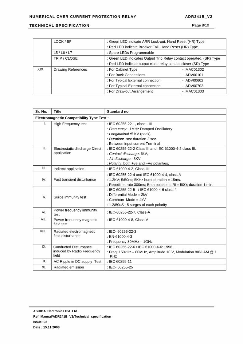
NUMERICAL OVER CURRENT PROTECTION RELAY ADR241B_V2 TECHNICAL SPECIFICATION
ASHIDA Electronics Pvt. Ltd Ref: Manual/ADR241B_V2/Technical_specification Issue: 02 Date : 15.11.2008
Page 8/10
LOCK / BF : Green LED indicate ARR Lock-out, Hand Reset (HR) Type : Red LED indicate Breaker Fail, Hand Reset (HR) Type
L5 / L6 / L7 : Spare LEDs Programmable TRIP / CLOSE : Green LED indicates Output Trip Relay contact operated, (SR) Type
: Red LED indicate output close relay contact closer (SR) Type : For Cabinet Type - MAC01302 XIX. Drawing References
: For Back Connections - ADV00101 : For Typical External connection - ADV00602 : For Typical External connection - ADV00702 : For Draw-out Arrangement - MAC01303
Sr. No. Title Standard no.
Electromagnetic Compatibility Type Test : I. High Frequency test : IEC 60255-22-1, class - III
: Frequency : 1MHz Damped Oscillatory : Longitudinal :5 KV (peak) : Duration: sec duration 2 sec. : Between input current Terminal
II. Electrostatic discharge Direct application
: IEC 60255-22-2 Class III and IEC 61000-4-2 class III. : Contact discharge: 6kV, : Air discharge: 8KV : Polarity: both +ve and –Ve polarities.
III. Indirect application : IEC-61000-4-2, Class-III
IV. Fast transient disturbance : IEC 60255-22-4 and IEC 61000-4-4, class A : 1.2KV; 5/50ns; 5KHz burst duration = 15ms. : Repetition rate 300ms; Both polarities; Ri = 50Ω; duration 1 min.
V. Surge immunity test
: IEC 60255-22-5 / IEC 61000-4-6 class 4 : Differential Mode = 2kV : Common Mode = 4kV : 1.2/50uS , 5 surges of each polarity
VI. Power frequency immunity test : IEC-60255-22-7, Class-A
VII. Power frequency magnetic field test
: IEC-61000-4-8, Class-V
VIII. Radiated electromagnetic field disturbance
: IEC- 60255-22-3 : EN-61000-4-3 : Frequency 80MHz – 1GHz
IX. Conducted Disturbance induced by Radio Frequency field
: IEC 60255-22-6 / IEC 61000-4-6: 1996. : Freq. 150kHz – 80MHz, Amplitude 10 V, Modulation 80% AM @ 1
KHz X. AC Ripple in DC supply Test : IEC 60255-11 XI. Radiated emission : IEC- 60255-25

NUMERICAL OVER CURRENT PROTECTION RELAY ADR241B_V2 TECHNICAL SPECIFICATION
ASHIDA Electronics Pvt. Ltd Ref: Manual/ADR241B_V2/Technical_specification Issue: 02 Date : 15.11.2008
Page 9/10
Insulation tests: XII. High Voltage Test
: IEC 60255-5. class - III : At 2.5kV 50Hz between all terminal connected together and earth
for 1 minutes XIII. Impulse Voltage Test
: IEC60255-5. class - III : Test voltage: 5KV (peak) 1.2 / 50us, : Energy :0.5 J, : Polarity : + ve and – Ve : Nos. of impulses : 3 positive and 3 negative impulse : Duration between Impulses : 5 sec.
Environmental tests: XIV. Cold test Storage test : IEC-60068-2-1
XV. Dry heat test : IEC-60068-2-2
XVI. Damp heat test, steady state : IEC-60068-2-3
XVII. Damp heat test, cyclic : IEC-60068-2-30 CE compliance
XVIII. Immunity : IEC-60255-26
XIX. Emissive Test : IEC- 60255-26
XX. Low voltage directive : EN-50178 Mechanical tests
XXI. Vibration : IEC 60255-21-1 class 1 : Frequency Range = 10Hz – 150Hz , acceleration. = 1gn (9.8 m/s2) : Sweep rate 1 octave/min; 20 cycle in 3 orthogonal axis.
XXII. Shock and bump : IEC- 60255-21-2
XXIII. Seismic : IEC-60255-21-3

NUMERICAL OVER CURRENT PROTECTION RELAY ADR241B_V2 TECHNICAL SPECIFICATION
ASHIDA Electronics Pvt. Ltd Ref: Manual/ADR241B_V2/Technical_specification Issue: 02 Date : 15.11.2008
Page 10/10
6.6 Revision Note
Issue Date Discription
01 06.05.2008 Original Version
02 15.11.2008 Typo Error Corrected.

NUMERICAL OVER CURRENT PROTECTION RELAY ADR241B_V2 APPLICATION GUIDE
ASHIDA Electronics Pvt. Ltd. Ref: Manual/ADR241B_V2/Application Issue: 02 Date : 15.11.2008
Page 1/16
APPLICATION GUIDE

NUMERICAL OVER CURRENT PROTECTION RELAY ADR241B_V2 APPLICATION GUIDE
ASHIDA Electronics Pvt. Ltd. Ref: Manual/ADR241B_V2/Application Issue: 02 Date : 15.11.2008
Page 2/16
CONTENTS
7.1 Main function 3
7.2 Over Current Element 3
7.3 Earth Fault Element 3
7.4 Inverse Time Curve 4
7.4.1 C1 - Normal Inverse 1 (10 Times 3.0 sec) 5
7.4.2 C2 - Normal Inverse 2 (10 Times 1.3 sec) 6
7.4.3 C3 - Very Inverse (10 Times 1.5 sec) 7
7.4.4 C4 - Extremely Inverse (10 Times 0.8 sec) 8
7.4.5 C5 - Long Time Inverse (10 Times 13.3 sec) 9
7.5 Trip Circuit Supervision 10
7.6 Auto Recloser Logic 10
7.7 Breaker Failure Logic 10
7.8 Negative Sequence Over Current 11
7.9 Programmable Di/DO and LED 11
7.10 Monitoring Function (Event, Disturbance Recorder) 11
7.11.1 Wiring Diagram – External EF for EF protection 12
7.11.2 Wiring Diagram – Internal EF for EF Protection 13
7.12 Trip Diagram 14
7.13 Logic Diagram of RL1 to RL5 and LED 15
7.14 Revision Note 16

NUMERICAL OVER CURRENT PROTECTION RELAY ADR241B_V2 APPLICATION GUIDE
ASHIDA Electronics Pvt. Ltd. Ref: Manual/ADR241B_V2/Application Issue: 02 Date : 15.11.2008
Page 3/16
7.1. Main Functions The ADR241B are having following protection functions.
1. 3 stage phase over current element. (Ip>,Ip>> and Ip>>>).
2. 3 stages of 3Io (internally derived EF) (3Io>, 3Io>> and 3Io>>>).
3. 3 stages of Ie (externally EF or REF) (Ie>, Ie>> and Ie>>>).
4. 2 stages of I2 (internally derived Negative Phase Sequence) (I2>> and I2>>>).
5. Trip Circuit Super vision.
6. Breaker Failure Detection.
7. Monitoring Functions.
8. Auto Recloser Relay (ARR).
9. Digital Input / Output Assignment
Each of these functions are independently programmable and can be enable or disable
by user depending upon requirement
7.2. Over Current Element:
The ADR241B is member of Ashida Numerical Relay family design for protection general
feeder. The relay has got three independent stages of over current (IP>, IP>>, & IP>>>).
Stage 1 (>) stage 2 (>>) can be programmed as IDMT or definite time. All major international
IDMT curves are available. Stage 3 (>>>) can be programmed instantaneous or define time.
Range of for stage 1 and 2 is 10% to 200% for phase and 10 to 200% for EF. For stage 3
phase 50% - 2000% The output of stage 1 (IP>) is separate and not connected to trip
contact. The output of Ip> can be assigned to any of 5 programmable relay through key
board. While output of IP>> and IP>>> is connected to trip element. Thus IP> can be used
as ALARM before trip or can be used to trip another CB before tripping main CB.
Although the curves tend towards infinite when the current approaches Is (general
threshold), the minimum guaranteed value of the operating current for all the curves with the
inverse time characteristic is 1.1Is (with a tolerance of ± 0.05Is).
7.3. Earth Fault Element:
The relay has got two different type of Earth Fault one is marked as 3Io and another is
marked as Ie. The 3Io is derived internally by software through phase current while Ie is
measured from external CT. Thus Ie can be used as Core Balance CT(CBCT) or Restricted
EF (REF). Each EF is having 3 stages (>, >>, & >>>). Stage 1 (>) stage 2 (>>) can be
programmed as IDMT or definite time. All major international IDMT curves are available.
Stage 3 (>>>) can be programmed instantaneous or define time. Range of for stage 1 and 2
is 10% to 200%, for stage 3 phase 50% - 2000%. The output of stage 1 (3Io>) is separate
and not connected to trip contact. The output of > can be assigned to any of 5 programmable
relay through key board. While output of >> and >>> is connected to trip element. Thus I>

NUMERICAL OVER CURRENT PROTECTION RELAY ADR241B_V2 APPLICATION GUIDE
ASHIDA Electronics Pvt. Ltd. Ref: Manual/ADR241B_V2/Application Issue: 02 Date : 15.11.2008
Page 4/16
can be used as ALARM before trip or can be used to trip another CB before tripping main
CB. The separate output contact allows to use each stage for independent function such as
stage 1 can be used for ALARM stage 2 for tripping or both can be use for tripping
independent CB. Each stage can enable or disable depend upon application.
7.4. Inverse Time Curves: -
The each stage thresholds for phase (earth) over current can be selected with an Inverse
Definite Minimum Time (IDMT) characteristic. The time delay is calculated with a
mathematical formula
Curve Type Description A B
C1 Standard Inverse_1 0.14 0.02 C2 Standard Inverse_2 0.60 0.02 C3 Very Inverse 13.5 1 C4 Extremely inverse 80 2 C5 Long Time Inverse 120 1 C6 Define Time - -
The separate output contact allows to use each stage for independent function such as
stage 1 can be used for ALARM stage 2 for tripping or both can be use for tripping
independent CB. Each stage can enable or disable depend upon application.
K * aI
Iref
b1
t =K * aI
Iref
b1
t =K * aI
Iref
I
Iref
b1
t =K * aI
Iref
b1
t =K * aI
Iref
b1
t =K * aI
Iref
I
Iref
b1
t =


NUMERICAL OVER CURRENT PROTECTION RELAY ADR241B_V2 APPLICATION GUIDE
ASHIDA Electronics Pvt. Ltd. Ref: Manual/ADR241B_V2/Application Issue: 02 Date : 15.11.2008
Page 10/16
7.5. Trip circuit Supervision :-
The ADR241B is having 2 separate digital opto-coupler status input which can be used to
continuously monitor continuity of trip-circuit. The general scheme is as shown in fig. 4.
Relay monitor Trip coil continuity through CB NO during close condition and through CB NC
during Trip condition. If any discontinuity observed it generate Alarm signal.
The output marked as PROTH (Protection healthy) is normally is ON and become OFF at
following condition
When DC supply is not sufficient (DC fail)
When T1 and T2 both active and both inactive. i.e CB NO as will as CB NC are both
close or open. Relay detects any internal hard ware Error.
7.6. Auto Recloser Logic:- The ADR241B is provided with 4 shot auto recloser function. There are 5 timer for auto
recloser 1) Dead Time for shot 1 (DT1) 2) Dead Time for shot 2 (DT2) 3) Dead Time for shot
3 (DT3) 4) Dead Time for shot 4 (DT4) and 5) Reclaim Time (RT). After clearing of fault
AD241B trigger dead Time 1 i.e DT1. After the time delay Relay provides reclose command
and start reclaim timer RT. If second fault occur during RT relay trigger Dead Time 2 i.e DT2.
If third fault occur during RT relay trigger Dead Time 3 i.e DT3, If Fourth fault occur during
RT relay trigger Dead Time 4 i.e DT4 and after time delay it again provide reclose command
and retrigger RT. If fifth fault occur during RT Relay generate Lock-Out alarm and block
further reclose. The Lock-Out condition can be reset locally as well remotely by SCADA
through communication digital status input.
7.7. Breaker Failure Detection:-
Normally after tripping current should become Zero within 100 – 200ms time depend upon
type of fault and breaker mechanism. After Fault ADR241B trigger internal timer (settable
from 0.1s to 1.0s) If fault is not cleared during this time then relay declare as Breaker fail
(LBB function) and change another contacts. This contact is marked as Breaker Fail can be
used to trip back up breaker or can be used to generate ALARM signal.
1
62
B+
B-
TC
CB NO
CB NC
Fig.4 Trip Circuit Logic
1
62
To Relay CPU
To Relay CPU
TCCOM
T1
T2
1
62
B+
B-
TC
CB NO
CB NC
Fig.4 Trip Circuit Logic
1
62
To Relay CPU
To Relay CPU1
62
B+
B-
TC
CB NO
CB NC
Fig.4 Trip Circuit Logic
1
62
To Relay CPU
To Relay CPU
TCCOM
T1
T2

NUMERICAL OVER CURRENT PROTECTION RELAY ADR241B_V2 APPLICATION GUIDE
ASHIDA Electronics Pvt. Ltd. Ref: Manual/ADR241B_V2/Application Issue: 02 Date : 15.11.2008
Page 11/16
7.8. Negative sequence over current (46)
The ADR241B relay will be included programmable function to detect unbalanced fault
conditions. When earth fault elements are not operated or not sufficiently sensitive. The
ADR241B include negative phase sequence over current element it can be programmed as
IDMT or definite time the actual setting range will be finalized during later stage of design
7.9. Programmable DI/DO and LED :-
The ADR241B has got 5 digital outputs, 5 opto-isolated input and 6 general purpose LEDs.
These can be programmed by local key board. Any logical of physical status can be assigned
to any relay contact.
7.10. Monitoring Functions (Event, Disturbance Record) :-
Apart from basic protection functions. Relay is continuously monitors all substations
operation through status, it internal functions, internal hardware etc. if any changed is
observed it marked as event. Such type of events is stored in internal non-volatile memory
along with time stamped. Following some of the events. Relay PKP, Relay Reset, CB Trip,
CB close, changed of any digital status input, Relay setting changed etc.
Up to 100 such event can be stored and can be download for detailed analysis. Apart from
Event record Relay also record actual waveform of current along with all digital and logical
status during fault condition. Up to 20 such waveforms can be recorded; the duration of
disturbance record is 1 sec. This waveform can be downloaded through communication port
for further analysis.

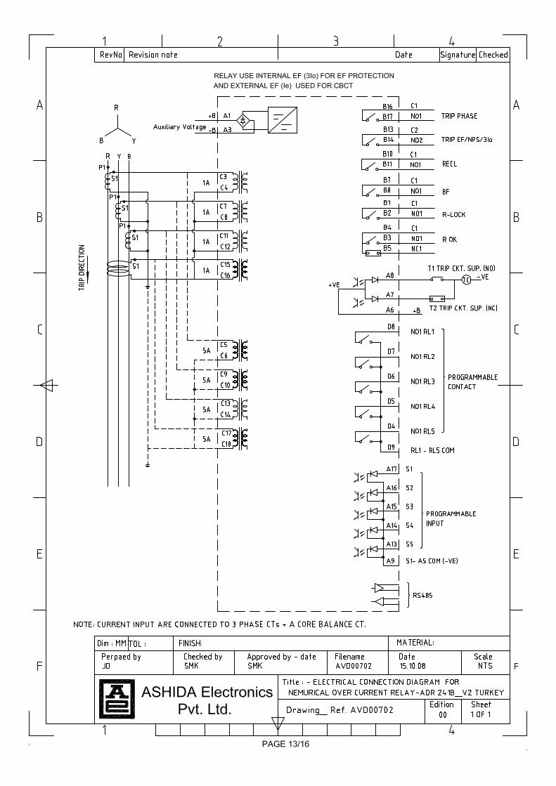

NUMERICAL OVER CURRENT PROTECTION RELAY ADR241B_V2 APPLICATION GUIDE
ASHIDA Electronics Pvt. Ltd. Ref: Manual/ADR241B_V2/Application Issue: 02 Date : 15.11.2008
Page 14/16
Digital Input / Digital Output
The ADR241B relay has got large nos. of setting and functions, Many times all the functions are not
needed and it is totally depends upon application , system under protection etc. The ADR241B
provide very innovative technique to optimized external wiring. The relay provided with 2NO trip
contact which is general trip and it is common to stage 2 and stage 3 of most of the function.
Following logic diagram
7.12 Trip Diagram
TRIP
&IE>>
IE>>Enable
&IE>>>
IE>>>Enable
&3Io>>
3Io>>Enable
&3Io>>>
3Io>>>Enable
&I2>>
I2>>Enable
&I2>>>
I2>>>Enable
&
&
&
&IP>>Y
&IP>>R
&IP>>B
IP>>Enable
IP>>>Y
IP>>>R
IP>>>BIP>>>Enable
&TEST
TEST Enable
TRIP
&IE>>
IE>>Enable
&IE>>>
IE>>>Enable
&3Io>>
3Io>>Enable
&3Io>>>
3Io>>>Enable
&I2>>
I2>>Enable
&I2>>>
I2>>>Enable
&
&
&
&IP>>Y
&IP>>R
&IP>>B
IP>>Enable
IP>>>Y
IP>>>R
IP>>>BIP>>>Enable
&TEST
TEST Enable

NUMERICAL OVER CURRENT PROTECTION RELAY ADR241B_V2 APPLICATION GUIDE
ASHIDA Electronics Pvt. Ltd. Ref: Manual/ADR241B_V2/Application Issue: 02 Date : 15.11.2008
Page 15/16
ADR241B has got 5 programmable relay and 8 programmable LED they can be assign to different
protection functions from key board. The method programming is given in user interface chapter.
Following logic diagram explain the functionality.
7.13 Logic diagram for RL1 to RL5 and Leds
&IE>
IE>Enable
&IE>>
IE>>Enable
&3Io>
3Io>Enable
&3Io>>
3Io>>Enable
&I2>>
I2>>Enable
&I2>>>
I2>>>Enable
&
&
&
&
IP>Y&
IP>R
&
IP>BIP>Enable
IP>>Y
IP>>R
IP>>BIP>>Enable
&
&
&
IP>>>Y
IP>>>R
IP>>>BIP>>>Enable
&IE>>>
IE>>>Enable
&3Io>>>
3Io>>>Enable
Not Connected
SR
HRSR Q
LED Reset
RL1---
RL5
&IE>
IE>Enable
&IE>>
IE>>Enable
&3Io>
3Io>Enable
&3Io>>
3Io>>Enable
&I2>>
I2>>Enable
&I2>>>
I2>>>Enable
&
&
&
&
IP>Y&
IP>R
&
IP>BIP>Enable
IP>>Y
IP>>R
IP>>BIP>>Enable
&
&
&
IP>>>Y
IP>>>R
IP>>>BIP>>>Enable
&IE>>>
IE>>>Enable
&3Io>>>
3Io>>>Enable
Not Connected
SR
HRSR Q
LED Reset
RL1---
RL5

NUMERICAL OVER CURRENT PROTECTION RELAY ADR241B_V2 APPLICATION GUIDE
ASHIDA Electronics Pvt. Ltd. Ref: Manual/ADR241B_V2/Application Issue: 02 Date : 15.11.2008
Page 16/16
7.14 Revision Note
Issue Date Description 01 06.05.2008 Original Version 02 15.11.2008 Typo Error Corrected

NUMERICAL OVER CURRENT PROTECTION RELAY ADR241B_V2 COMMUNICATION
ASHIDA Electronics Pvt. Ltd. Ref: Manual/ADR241B_V2/Communication Issue: 02 Date : 15.11.2008
Page 1/9
COMMUNICATION

NUMERICAL OVER CURRENT PROTECTION RELAY ADR241B_V2 COMMUNICATION
ASHIDA Electronics Pvt. Ltd. Ref: Manual/ADR241B_V2/Communication Issue: 02 Date : 15.11.2008
Page 2/9
CONTENTS
8.1 IEC60870-5-103 INTERFACE for ADR241B 3
8.2 Physical connection and link layer 3
8.3 Initialization 4
8.4 Time synchronization 5
8.5 General interrogation 5
8.6 Cyclic measurements 5
8.7 Disturbance records 5
8.8 APPENDIX 5
8.8.1 Frames in Monitor Direction 5
8.8.1.1 System Functions in monitor direction 5
8.8.1.2 Status indications in monitor direction 6
8.8.1.3 Fault indications in monitor direction 6
8.8.1.4 Measurands in monitor direction 7
8.8.1.5 Private frames in monitor direction 7
8.8.1.6 Disturbance data transmission in monitor direction 7
8.8.2 Frames in Control Direction 8
8.8.2.1 Private frames in Control direction 8
8.8.2.2 System Functions in control direction: 8
8.8.2.3 General commands in control direction 8
8.8.2.4 Disturbance data transmission related messages in control direction 8
8.8.2.5 Actual Channel: Used for DR Transmission: 8
8.9 Revision Note 9

NUMERICAL OVER CURRENT PROTECTION RELAY ADR241B_V2 COMMUNICATION
ASHIDA Electronics Pvt. Ltd. Ref: Manual/ADR241B_V2/Communication Issue: 02 Date : 15.11.2008
Page 3/9
8.1 IEC60870-5-103 INTERFACE for ADR241B
IEC60870-5-103 applies to protection equipment with coded bit serial data transmission for exchanging information with control systems. This relay supports compatibility level 2.
The following IEC60870-5-103 facilities are supported by this interface:
• Initialization (Reset) • Time Synchronization • Event Record Extraction • General Interrogation • Cyclic Measurements • General Commands • Disturbance Records
8.2 Physical connection and link layer
Connection is available for IEC60870-5-103 through the front RS232 port as well as the rear RS485 port. The parameters of the communication are the following: • No Parity, Odd Parity & Even Parity
• 8 Data bits
• 1 stop bit
• Data rate 1200, 2400, 9600, 19200 38400 or 57600 bauds
Electrical connection for Front RS232 Port
P1
CONNECTOR DB9 Male
594837261
P1
CONNECTOR DB9 Femle
594837261
ADR241BComputer

NUMERICAL OVER CURRENT PROTECTION RELAY ADR241B_V2 COMMUNICATION
ASHIDA Electronics Pvt. Ltd. Ref: Manual/ADR241B_V2/Communication Issue: 02 Date : 15.11.2008
Page 4/9
RS485/RS422 communication port Electrical Connection provided at back of Relay
RS485/422 PORT
D9 Male
594837261
RX -
RX +
TX +
TX -
Rx+ and Rx- are Input to relayTx+ and Tx- are output from relay
8.3 Initialization
A reset of the communication function is affected by means of a reset command from the
control system. This is generally transmitted by control system when:
• Control system is initialized;
• The protection does not respond during a certain period. The reset command can be transmitted as:
• Reset frame count bit (FCB), or
• Reset communication unit (CU).
Reset CU will clear any unsent message frames in the relay’s transmit buffer.
The relay will respond to the reset command with an identification message ASDU 5, the
Cause of Transmission COT of this response will be either Reset CU or Reset FCB
Depending on the nature of the reset command. The following information will be contained in
the data section of this ASDU.
Manufacturer Name: ASHIDA
The Software Identification Section will contain the first four characters of the relay model
number to identify the type of relay.
In addition to the above identification message, if the relay has been powered up it will also
produce a power up event.

NUMERICAL OVER CURRENT PROTECTION RELAY ADR241B_V2 COMMUNICATION
ASHIDA Electronics Pvt. Ltd. Ref: Manual/ADR241B_V2/Communication Issue: 02 Date : 15.11.2008
Page 5/9
8.4 Time synchronization
If the time synchronization message is sent as a send/confirm message then the relay will
respond with a confirm. Whether the time synchronization message is sent as a send confirm
or a broadcast (send/no reply) message, a time synchronization message will be returned as
Class 1 data.
8.5 General interrogation
In the control direction, general interrogation (GI) initiated by means of a GI command.
It is used to read the status of the relay, the function numbers, information numbers and
common address offsets that will be returned during the GI cycle.
When the list of messages subject to GI has been processed following by a GI command,
A GI termination message is then transmitted. A new cycle is not initiated in protection
equipment until a new GI impulse is received from control equipment.
8.6 Cyclic measurements
The relay will produce measured values using ASDU 3 and ASDU 9 alternately on a cyclical
basis, these can be read from the relay using a Class 2 poll. The measurands transmitted by
the relay are sent as a proportion of 1.2 times the rated value of the analogue value.
8.7 Disturbance records
The disturbance records stored by the relay can be extracted using the mechanism defined in
the IEC60870-5-103 standard. Disturbance data transmission initiated, first binary values are
transmitted first, followed by disturbance values. Initial status of the binary values transmitted
first, followed by tags for changed values.
Disturbance values are transmitted with increasing channel numbers. All ASDUs are
transmitted as data class 1 in the link layer.
8.8 APPENDIX 8.8.1 Frames in Monitor Direction 8.8.1.1 System Functions in monitor direction
INF Description GI TYP COT FUN (typical)
<0> End of general interrogation - 8 10 255 <0> Time synchronization - 6 8 255 <2> Reset FCB - 5 3 160

NUMERICAL OVER CURRENT PROTECTION RELAY ADR241B_V2 COMMUNICATION
ASHIDA Electronics Pvt. Ltd. Ref: Manual/ADR241B_V2/Communication Issue: 02 Date : 15.11.2008
Page 6/9
<3> Reset CU - 5 4 160 <4> Start/Restart - 5 5 160 <5> Power on - 5 6 160
8.8.1.2 Status indications in monitor direction
INF Description GI TYP COT FUN(typical) <18> Protection active X 1 9 160 <21> Test X 1 9,11 127 <19> LED Reset - 1 1,7,11 160 <27> Status 1 X 1 1,7,9,11 160 <28> Status 2 X 1 1,7,9,11 160 <29> Status 3 X 1 1,7,9,11 160 <30> Status 4 X 1 1,7,9,11 160 <31> Status 5 X 1 1,7,9,11 127
8.8.1.3 Fault indications in monitor direction
INF Description GI TYP COT FUN (typical) <64> Start/ pick-up L1 X 2 1,7,9 160 <65> Start/ pick-up L2 X 2 1,7,9 160 <66> Start/ pick-up L3 X 2 1,7,9 160 <67> Start/ pick-up N X 2 1,7,9 160
<117> OCR 1 pick-up X 2 1,7,9 126 <103> OCR 2 pick-up X 2 1,7,9 126 <105> OCR 3 pick-up X 2 1,7,9 126 <84> General start/ pickup X 2 1,7,9 160 <69> Trip L1 - 2 1,7 160 <70> Trip L2 - 2 1,7 160 <71> Trip L3 - 2 1,7 160 <90> Trip I> - 2 1,7 160 <91> Trip I>> - 2 1,7 160
<104> Trip I>>> - 2 1,7 126 <92> Trip IN> - 2 1,7 160 <93> Trip IN>> - 2 1,7 160
<121> Trip IN>>> - 2 1,7 126 <68> General Trip - 2 1,7 160 <85> Breaker failure - 2 1,7 160
<123> 3IO Stage 1 pick-up X 2 1,7,9 126 <124> 3IO Stage 1 Trip - 2 1,7 126 <125> 3IO Stage 2 pick-up X 2 1,7,9 126

NUMERICAL OVER CURRENT PROTECTION RELAY ADR241B_V2 COMMUNICATION
ASHIDA Electronics Pvt. Ltd. Ref: Manual/ADR241B_V2/Communication Issue: 02 Date : 15.11.2008
Page 7/9
<126> 3IO Stage 2 Trip - 2 1,7 126 <127> 3IO Stage 3 pick-up X 2 1,7,9 126 <128> 3IO Stage 3 Trip - 2 1,7 126 <129> NPS Stage 2 pick-up X 2 1,7,9 126 <130> NPS Stage 2 Trip - 2 1,7 126 <131> NPS Stage 3 pick-up X 2 1,7,9 126 <132> NPS Stage 3 Trip - 2 1,7 126
8.8.1.4 Measurands in monitor direction
INF Description GI TYP COT FUN (typical) <148> Measurand I1, I2, I3 - 9 2 160 <14> Measurand I4 - 9 2 160
8.8.1.5 Private frames in monitor direction
INF Description GI TYP COT FUN (typical) <0> Fault Data - 246 11 160
8.8.1.6 Disturbance data transmission in monitor direction
INF Description GI TYP COT FUN (typical)
<0> List of Recorded Disturbances X 23 31 160
<0> Ready for Transmission of Disturbance Data
- 26 31 160
<0> Ready for Transmission of Tags - 28 31 160
<0> Transmission of Tags - 29 31 160
<0> End of Transmission - 31 31 160
<0> Ready for Transmission of Channel
- 27 31 160
<0> Transmission of Disturbance Data - 30 31 160

NUMERICAL OVER CURRENT PROTECTION RELAY ADR241B_V2 COMMUNICATION
ASHIDA Electronics Pvt. Ltd. Ref: Manual/ADR241B_V2/Communication Issue: 02 Date : 15.11.2008
Page 8/9
8.8.2 Frames in Control Direction 8.8.2.1 Private frames in Control direction
INF Description TYP COT FUN (typical) <0> Fault List Request 24 11 160 <0> Fault Data Request 245 11 127
8.8.2.2 System Functions in control direction
INF Description TYP COT FUN (typical) <0> Initialization of general interrogation 7 9 <255> <0> Time synchronization 6 8 <255>
8.8.2.3 General commands in control direction
INF Description COM TYP COT FUN (typical) <19> LED Reset ON 20 20 160 <124> Output 1 (Trip Relay) ON 20 20 160
8.8.2.4 Disturbance data transmission related messages in control direction
INF Description GI TYP COT FUN (typical) <0> Order for Disturbance data
Transmission - 24 31 160
<0> Acknowledgement for Disturbance Data transmission
- 25 31 160
8.8.2.5 Actual Channel: Used for DR Transmission
INF Description <1> IR <2> IY <3> IB <4> IN

NUMERICAL OVER CURRENT PROTECTION RELAY ADR241B_V2 COMMUNICATION
ASHIDA Electronics Pvt. Ltd. Ref: Manual/ADR241B_V2/Communication Issue: 02 Date : 15.11.2008
Page 9/9
8.9 Revision Note
Issue Date Description 01 06.05.2008 Original Version 02 15.11.2008 Minor Typo Error Corrected.

NUMERICAL OVER CURRENT PROTECTION RELAY ADR241B_V2 INSTALLATION & COMMISSIONING
ASHIDA Electronics Pvt. Ltd. Ref: Manual/ADR241B_V2/ INSTALLATION Issue: 02 Date : 15.11.2008
Page 1/24
INSTALLATION COMMISSIONING &
RELAY TESTING

NUMERICAL OVER CURRENT PROTECTION RELAY ADR241B_V2 INSTALLATION & COMMISSIONING
ASHIDA Electronics Pvt. Ltd. Ref: Manual/ADR241B_V2/ INSTALLATION Issue: 02 Date : 15.11.2008
Page 2/24
CONTENTS
9.1 Installation 4
9.1.1 Relay Connection & Diagram 4
9.1.2 Before energising following should be checked 4
9.1.3 Relay operating condition 4
9.1.4 CT Circuit 4
9.1.5 Insulation 4
9.2. Commissioning 5
9.2.1 Commissioning Test, Required Equipment 5
9.2.2 Checking of External Circuitry 5
9.2.2.1 Relay Back Terminal Wiring 5
9.2.2.2 Visual Inspection 5
9.2.2.3 Earthing 6
9.2.2.4 CT Polarity 6
9.2.3 Checking of Relay Setting 6
9.2.4 Final Checking 7
9.2.5 Commissioning Record Sheet 7
9.2.5.1 Relay identification 7
9.2.5.2 Commissioning Test Report 8
9.2.5.3 Commissioning record sheet for ADR241B_V2 Relay. 9
9.3 Post instillation / Commissioning observation 10
9.4 Testing of Relay 10
9.4.1 Relay Calibration 10
9.4.2 Diagram for Pickup and Timing Test 12
9.4.3 Testing of Over Current IP>> Protection 13
9.4.3.1 Pickup Test for Over Current IP>> 13
9.4.3.2 IDMT Time Test for Over Current IP>> 13
9.4.3.3 Pickup Test for Over Current Instantaneous Element IP>> 15
9.4.3.4 Operating Time Test for Over Current Instantaneous Element IP>> 16
9.4.4 Testing of 3Io>> Protection 16
9.4.4.1 Pickup Test for 3Io >> 16
9.4.4.2 IDMT Time Test for 3Io>> 17
9.4.4.3 Operating Time Test for Instantaneous Element 3Io>> 18

NUMERICAL OVER CURRENT PROTECTION RELAY ADR241B_V2 INSTALLATION & COMMISSIONING
ASHIDA Electronics Pvt. Ltd. Ref: Manual/ADR241B_V2/ INSTALLATION Issue: 02 Date : 15.11.2008
Page 3/24
9.4.5 Testing of Earth Fault Ie>> Element 19
9.4.5.1 Pickup Test for Earth Fault Ie>> 19
9.4.5.2 IDMT Time Test for Earth Fault Ie>> 19
9.4.5.3 Operating Time Test for Earth Fault Instantaneous Element Ie>> 21
9.4.6 Testing of NPS (Negative Phase Sequence Element) 21
9.4.7 Testing of Annunciation for Both Over Current & Earth Fault 22
9.5 Other Functional Test 23
9.6 Revision Note 24

NUMERICAL OVER CURRENT PROTECTION RELAY ADR241B_V2 INSTALLATION & COMMISSIONING
ASHIDA Electronics Pvt. Ltd. Ref: Manual/ADR241B_V2/ INSTALLATION Issue: 02 Date : 15.11.2008
Page 4/24
9.1. INSTALLATION 9.1.1. Relay Connection and Diagram
Before installation of the relay check the correct working procedure as to ensure safety and
the equipment documentation. Terminal exposed during installation may present a hazardous
voltage unless the equipment is electrically isolated. Any disassembly of the equipment may
expose parts at hazardous voltage. Electronic parts may be damaged if suitable electrostatic
discharge (ESD) precautions are not taken. Voltage and current connection should be made
using insulated crimp termination to ensure that terminal block insulation requirement are
maintained for safety. To ensure that wires are correctly terminated the correct crimp terminal
and tool for wire size should be used. The equipment must be connected in accordance with
the appropriate connection diagram.
9.1.2. Before energising following should be checked
a. Voltage rating and polarity.
b. CT circuit rating and integrity of connection.
c. Protective fuse rating.
d. Integrity of the earthing connection.
e. Voltage and current rating of external wiring, applicable to the application.
9.1.3. Relay Operating Condition
The equipment should be operated within the specified electrical and environmental limits. 9.1.4. Current Transformer Circuit
Do not open the secondary circuit of a live CT since the high voltage produce may be lethal to
personnel and could damage insulation. Generally, for safety, the secondary of the line CT
must be shorted before opening any connection to it. For ADR241_V2, terminal block for
current transformer termination has automatic CT shorting on removal of the module.
Therefore external shorting of the CTs may not be required.
9.1.5. Insulation and dielectric strength testing
Insulation testing may leave capacitors charged up to a hazardous voltage. At the end of each
part of the test, the voltage should be gradually reduced to zero, to discharge capacitors,
since this may result in damage.

NUMERICAL OVER CURRENT PROTECTION RELAY ADR241B_V2 INSTALLATION & COMMISSIONING
ASHIDA Electronics Pvt. Ltd. Ref: Manual/ADR241B_V2/ INSTALLATION Issue: 02 Date : 15.11.2008
Page 5/24
9.2. COMMISSIONING 9.2.1. Commissioning Test, Required Equipment.
ADR241B_V2 are fully numerical in their design, it has self supervision function continuously
keeping track on its internal hardware and the movement, it detects failure of any component,
it gives message on LCD display. So with this important function the commissioning test do
not need to be as extensive as with non numerical relays. To communicate ADR241B_V2
relay is only necessary to verify that its functioning correctly. At the time of commissioning of
ADR241B_V2 relay following test equipments are sufficient.
a. Current injector (Single Phase) 0-50A.
b. Timer with precision 1ms.
c. Multimeter Precision 1%
d. Required Auxiliary supply
e. Connecting wire as per required length extension board etc.
9.2.2. Checking of External Circuit
9.2.2.1. Relay Back Terminal Wiring Ensure the relay wiring as per appropriate wiring diagram on back terminal of relay.
a. CT Secondary to be connected to the relay 1A or 5A. All screws on the CT wiring to be
properly tightened. Warning: Open circuit of CT secondary wiring can cause high voltage
produce which may be lethal and could damage insulation.
b. Auxiliary supply input of the relay with proper polarity as positive supply mark with +Ve
and negative supply as –Ve on back sticker. The supply rang is also mentioned on back
sticker. Confirm the auxiliary supply before energizing the relay it should be within range.
c. Trip contact connection as per given schematic diagram.
d. Alarm contact connection as per given schematic diagram.
e. Extra Annunciation contact connection as per requirement as site selectable contacts are
provided.
9.2.2.2. Visual inspection
Check external wiring corresponds to appropriate relay diagram. The reference ferrule no. of
external wiring and relay back sticker on top of the metal box.

NUMERICAL OVER CURRENT PROTECTION RELAY ADR241B_V2 INSTALLATION & COMMISSIONING
ASHIDA Electronics Pvt. Ltd. Ref: Manual/ADR241B_V2/ INSTALLATION Issue: 02 Date : 15.11.2008
Page 6/24
9.2.2.3. Earthing
Earthing sticker is put on the bottom screw of the equipment box at the back side of the relay.
Ensure the relay earthing connected to the local earth bar with several relays present, make
sure that the copper earth bar is properly installed for solidity connecting to the earthing
terminal of each relay equipment box.
9.2.2.4. CT Polarity
Ensure proper CTs are connected as per required maximum load current and their polarity.
When all polarity of CTs are properly connected, unbalance current flowing through earth fault
element will found approximately zero. Otherwise the relay will trip in earth fault after
energizing of C.B.
CT polarity can be checked by following method :
Momentarily battery +Ve to P1 & -Ve to P2 .The center zero ammeter connected with +Ve to
S1 and –Ve to S2, will deflect in +Ve direction if CT polarity is correct.
9.2.3. Checking of Relay Setting
The relay setting check ensures that all of application specific relay setting for the particular
installation have been correctly applied to the relay. Enter all setting manually via the relay
front panel interface.
The commissioning of following points:
a. Ensure over current and earth fault trip setting.
b. Ensure TMS setting of over current and Earth Fault are entered correctly as per required time grading between feeder and incomer.
c. Ensure trip count reset application which are selectable as HR (Hand Reset) or SR (Self Reset).
d. Ensure instantaneous HF setting done correctly and its definite time delay are applied properly as per required time grading between feeder and incomer.
e. Ensure selection of programmable extra annunciation duty contacts is as per required function.
f. Ensure connected CT primary ratio is applied properly as per existing feeder and incomer.
g. Ensure selected CT secondary from relay back terminal is match with selected CT Secondary from relay setting.
h. Ensure annunciation contact reset function which is selectable as HR (hand Reset) or SR (Self Reset).
i. Ensure measure of applied current is same as the current measure in CT secondary current and CT Primary current also.

NUMERICAL OVER CURRENT PROTECTION RELAY ADR241B_V2 INSTALLATION & COMMISSIONING
ASHIDA Electronics Pvt. Ltd. Ref: Manual/ADR241B_V2/ INSTALLATION Issue: 02 Date : 15.11.2008
Page 7/24
9.2.4. Final Checking
After completion of all relay functionality testing and relay setting check. Remove all tests as
temporary shorting leads etc. if it is necessary to disconnect any of the external wiring from
the relay in order to perform the wiring verification test. It should be ensured with the CT
connection are replaced in accordance with the relevant external connection or schemes
diagram. Ensure all fault & Annunciation contacts, trip contacts has been reset before leaving
relay.
If relay ADR241B_V2 is a newly installed or the CB has been just maintained the trip counter
of relay should be zero. This counter can be reset by using HW reset,LED reset and Up arrow
key.
To rest follow the instruction given below:
a. Press and hold ‘HW reset, LED reset’ key.
b. Now press and hold ’Up arrow key’.
c. Now release ‘HW Reset, LED reset’ and hold ‘Up arrow key’ until the following message is displayed
‘All Fault memory and password clear and all protection OFF press HW reset+ LED Reset’
d. Now press ‘HW Reset + LED Reset ’ and release to continue.
9.2.5. Commissioning record sheet 9.2.5.1. Relay identification
Commissioning Date: -
Commissioning Engineer: -
Substation Details: -
Circuit Details: -
ADR series relay model No. : - ADR 241B
Relay model No. : -
Relay Serial No. : -
Rated current : -
Rated Auxiliary Voltage: -
Communication Protocol: -
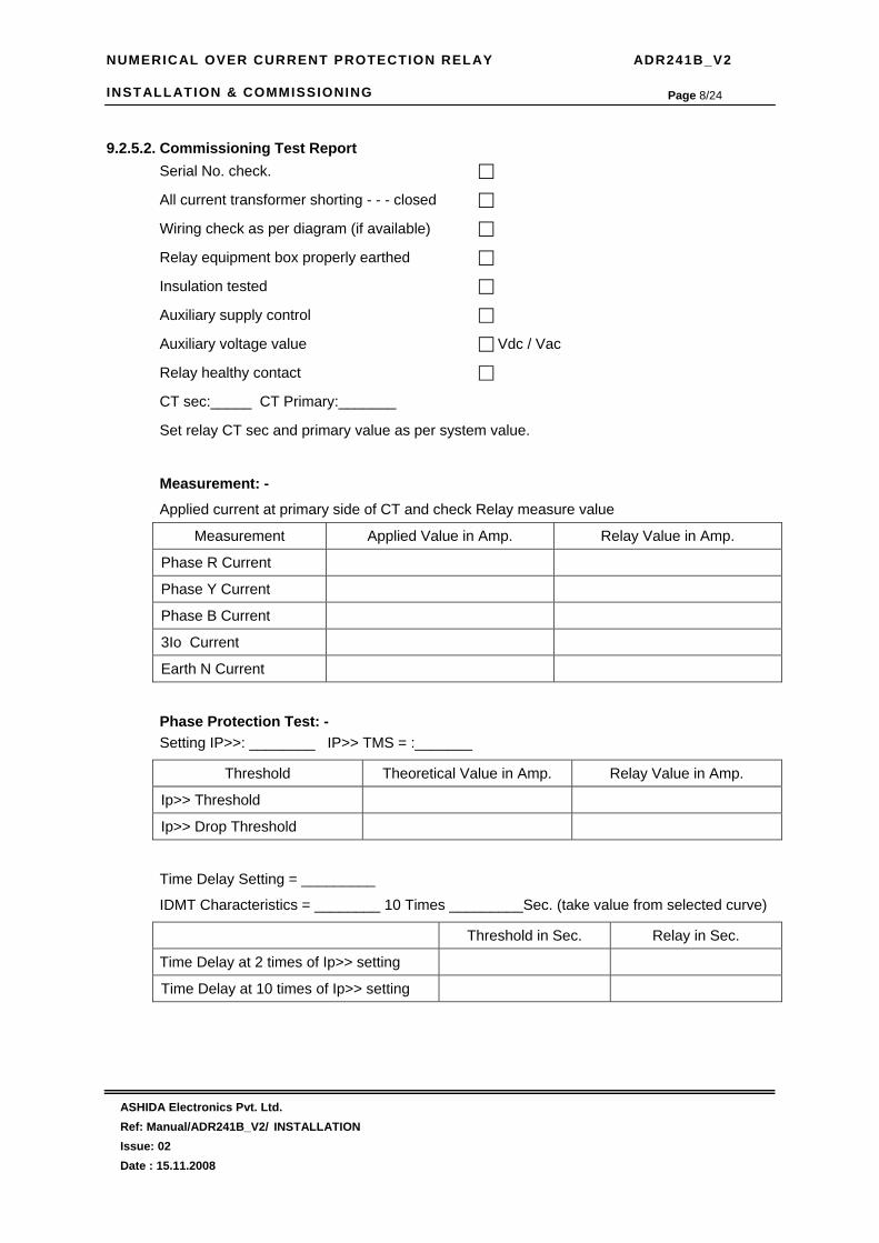
NUMERICAL OVER CURRENT PROTECTION RELAY ADR241B_V2 INSTALLATION & COMMISSIONING
ASHIDA Electronics Pvt. Ltd. Ref: Manual/ADR241B_V2/ INSTALLATION Issue: 02 Date : 15.11.2008
Page 8/24
9.2.5.2. Commissioning Test Report Serial No. check.
All current transformer shorting - - - closed
Wiring check as per diagram (if available)
Relay equipment box properly earthed
Insulation tested
Auxiliary supply control
Auxiliary voltage value Vdc / Vac
Relay healthy contact
CT sec:_____ CT Primary:_______
Set relay CT sec and primary value as per system value.
Measurement: -
Applied current at primary side of CT and check Relay measure value
Measurement Applied Value in Amp. Relay Value in Amp.
Phase R Current
Phase Y Current
Phase B Current
3Io Current
Earth N Current
Phase Protection Test: - Setting IP>>: ________ IP>> TMS = :_______
Threshold Theoretical Value in Amp. Relay Value in Amp.
Ip>> Threshold
Ip>> Drop Threshold
Time Delay Setting = _________
IDMT Characteristics = ________ 10 Times _________Sec. (take value from selected curve)
Threshold in Sec. Relay in Sec.
Time Delay at 2 times of Ip>> setting
Time Delay at 10 times of Ip>> setting

NUMERICAL OVER CURRENT PROTECTION RELAY ADR241B_V2 INSTALLATION & COMMISSIONING
ASHIDA Electronics Pvt. Ltd. Ref: Manual/ADR241B_V2/ INSTALLATION Issue: 02 Date : 15.11.2008
Page 9/24
Earth Protection Test: -
Setting 3Io>>: ________ 3Io>> TMS = :_______
Threshold Theoretical Value in Amp. Relay Value in Amp.
3Io>> Threshold
3Io>> Drop Threshold
Time Delay Setting = _________
IDMT Characteristics = __________ 10 Times _________Sec.
Threshold in Sec. Relay in Sec.
Time Delay at 2 times of 3Io>> setting
Time Delay at 10 times of 3Io>> setting
9.2.5.3. Commissioning record sheet for ADR241B_V2 Relay.
Password protection : -
Password : -
Setting Ref.
CT Ratio configuration menu
Line CT Primary connected ______A
Line CT Secondary
Protection menu:-
Phase Over Current : - (50/51)
Ip>> % trip setting = ______%
Ip>> Delay type setting IDMT
Normal Inverse 1 C1 Normal Inverse 2 C2
Very Inverse C3 Extremely Inverse C4
Long Time Inverse C5 Definite Time Delay C6
Ip TMS setting for IDMT
Ip>> IDMT Delay setting
51 IP>>> setting Yes No
IP>>> % Setting = ___%
IP> >> Delay Setting= _____Sec.

NUMERICAL OVER CURRENT PROTECTION RELAY ADR241B_V2 INSTALLATION & COMMISSIONING
ASHIDA Electronics Pvt. Ltd. Ref: Manual/ADR241B_V2/ INSTALLATION Issue: 02 Date : 15.11.2008
Page 10/24
Earth Fault Over Current (3Io) : - (50N/51N)
3Io>> % trip setting = ______%
3Io>> Delay type setting IDMT
Normal Inverse 1 C1 Normal Inverse 2 C2
Very Inverse C3 Extremely Inverse C4
Long Time Inverse C5 Definite Time Delay C6
3Io>> TMS setting for IDMT
3Io>> IDMT Delay setting
51N
3Io>>> setting Yes No
3Io>>> % Setting = ___%
3Io>> Delay Setting= _____Sec.
9.3. Post instillation / Commissioning observation
After successful installation conformer amount of existing load current in each phase (R, Y, B)
and Earth Fault (3Io). This can be confirmed with Analog/ Digital current meter available on
panel with relay primary and secondary current measurement window. In normal Balance
load condition the 3Io current should be vey low. Similarly Positive sequence current I1
should be approximately equal to average value of phase current while negative phase
sequence current should be very low. Trip test also can be carried out with test push button to
confirm trip circuit this test can be conducted without load also.
9.4 Testing of Relay 9.4.1 Relay Calibration
Before conducting actual test confirm relay calibration by following method. • Connect ADR 241B_V2 relay to current injector and timer as shown in diagram.
• Following chart shows terminal numbers of 1A / 5A CT connections.
Phase 1A 5A R C3, C4 C5, C6 Y C7, C8 C9, C10 B C11, C12 C13, C14
EF C15, C16 C17, C18
• Connect R CT terminals as per the chart.

NUMERICAL OVER CURRENT PROTECTION RELAY ADR241B_V2 INSTALLATION & COMMISSIONING
ASHIDA Electronics Pvt. Ltd. Ref: Manual/ADR241B_V2/ INSTALLATION Issue: 02 Date : 15.11.2008
Page 11/24
• Adjust rated CT Secondary Current 1A/5A. Observe the current value from measurement
menu. The actual current should match with relay display.
• Adjust trimpot if it shows difference in actual and standard source. Refer following table
for calibration.
Phase Trimpot R P1 Y P2 B P3
EF P4
• Repeat the same procedure for other element.
Note: The 3Io is internally derived zero sequence current from phase current. Before testing
of pick up timing check calibration from by giving known current from stable current
source for correct phase sequence and equal value. We recommend digital current sources such as Doble F610 or Omricon test set. Adjust current equal to rated input,
i.e. 1A for A input or 5A for 5A input. If all sources are same and equal then observed 3Io, I1 and I2 current display on relay measurement menu. The 3Io value should be
less than 0.05 , I1 = 1.0 or 5.0A (+/- 3%) depend upon relay 1/5A setting and actual current input. and I2 should be less then 0.05.


NUMERICAL OVER CURRENT PROTECTION RELAY ADR241B_V2 INSTALLATION & COMMISSIONING
ASHIDA Electronics Pvt. Ltd. Ref: Manual/ADR241B_V2/ INSTALLATION Issue: 02 Date : 15.11.2008
Page 13/24
9.4.3 TESTING OF OVER CURRENT PROTECTION 9.4.3.1 Pickup Test for Over Current IP>> :
1. Connect ADR 241B_V2 relay to current injector and timer as shown in diagram.
2. Select IP>> =50%,100%, and 200% as per table, IP>> TMS =x0.02
3. Switch on current injector and inject the current to relay.
4. Now start increasing the current using VI control (Variac) and observe the pickup indication of the relay.
5. When the injected current crosses IP>> % relay Pickup led will glow indicating relay pick-up condition. The relay gives trip signal. Note down this current value as pick value of relay.
6. At the same time the relay latches the fault in the current buffer.
7. Read that current fault and note down the trip current value.
8. Repeat the procedure for different pickup setting for different phases as per test report.
Pick-up Test (IN AMPS.)
IP>> % R Phase Y Phase B Phase Limit value(amp)
1A 5A 1A 5A 1A 5A 1A 5A Min Max Min Max 50% 0.5 0.55 2.0 2.75 100% 1.0 1.1 5.0 5.5 200% 2.0 2.2 10.0 11
Result : Pickup accuracy was found within _______________ (1.1 Time of set value)
9.4.3.2 IDMT Time Test for Over Current IP>> :
1. Set IP>> = and Ip>> TMS as per table.
2. Connect trip contacts (3 and 4) to stop terminals of Timer.
3. Adjust current to required value as per test report.
4. Reset the Timer.
5. Start the timer using start push button. The timer will stop automatically when relay gives trip command.
6. Note down the time value.
7. Repeat the procedure for different setting for different phases as per test report.
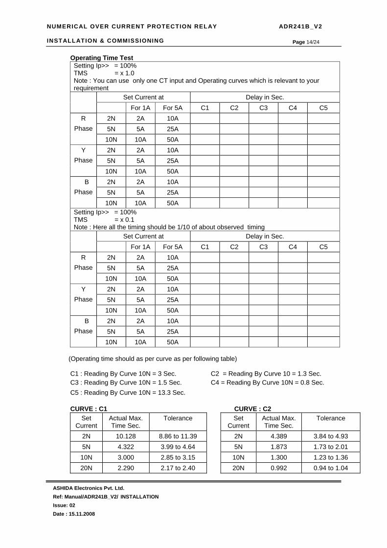
NUMERICAL OVER CURRENT PROTECTION RELAY ADR241B_V2 INSTALLATION & COMMISSIONING
ASHIDA Electronics Pvt. Ltd. Ref: Manual/ADR241B_V2/ INSTALLATION Issue: 02 Date : 15.11.2008
Page 14/24
Operating Time Test Setting Ip>> = 100% TMS = x 1.0 Note : You can use only one CT input and Operating curves which is relevant to your requirement
Set Current at Delay in Sec. For 1A For 5A C1 C2 C3 C4 C5
2N 2A 10A 5N 5A 25A
R Phase
10N 10A 50A 2N 2A 10A 5N 5A 25A
Y Phase
10N 10A 50A 2N 2A 10A 5N 5A 25A
B Phase
10N 10A 50A Setting Ip>> = 100% TMS = x 0.1 Note : Here all the timing should be 1/10 of about observed timing
Set Current at Delay in Sec. For 1A For 5A C1 C2 C3 C4 C5
2N 2A 10A 5N 5A 25A
R Phase
10N 10A 50A 2N 2A 10A 5N 5A 25A
Y Phase
10N 10A 50A 2N 2A 10A 5N 5A 25A
B Phase
10N 10A 50A (Operating time should as per curve as per following table)
C1 : Reading By Curve 10N = 3 Sec. C2 = Reading By Curve 10 = 1.3 Sec. C3 : Reading By Curve 10N = 1.5 Sec. C4 = Reading By Curve 10N = 0.8 Sec. C5 : Reading By Curve 10N = 13.3 Sec.
CURVE : C1 CURVE : C2
Set Current
Actual Max. Time Sec.
Tolerance Set Current
Actual Max. Time Sec.
Tolerance
2N 10.128 8.86 to 11.39 2N 4.389 3.84 to 4.93 5N 4.322 3.99 to 4.64 5N 1.873 1.73 to 2.01 10N 3.000 2.85 to 3.15 10N 1.300 1.23 to 1.36 20N 2.290 2.17 to 2.40
20N 0.992 0.94 to 1.04

NUMERICAL OVER CURRENT PROTECTION RELAY ADR241B_V2 INSTALLATION & COMMISSIONING
ASHIDA Electronics Pvt. Ltd. Ref: Manual/ADR241B_V2/ INSTALLATION Issue: 02 Date : 15.11.2008
Page 15/24
CURVE : C3 CURVE : C4 Set
Current Actual Max. Time Sec.
Tolerance Set Current
Actual Max. Time Sec.
Tolerance
2N 13.500 11.81 to 15.18 2N 26.667 23.33 to 30.00 5N 3.375 3.12 to 3.62 5N 3.333 3.08 to 3.58 10N 1.500 1.42 to 1.57 10N 0.808 0.76 to 0.84 20N 0.711 0.67 to 0.74
20N 0.201 0.19 to 0.21 CURVE : C5
Set Current Actual Max. Time Sec.
Tolerance
2N 120.000 105 .00 to 135.00 5N 30.000 27.75 to 32.25
10N 13.333 12.66 to 13.99 20N 6.316 6.00 to 6.63
9.4.3.3 Pick-up Testing for Over Current Instantaneous Element
1. Set IP>>> = 200%, IP>>> delay = 0.
2. Start increasing the current using variac when it crosses IP>>> % settings the relay gives trip signal and the timer will stop.
3. The unit latches the fault current and will display message as follows:
IP> : IP>> : TC : 0026 IP>>> : R
R = 10.00 Y = 00.10 B = 00.10 N = 000.0 Date : 01/09/05 Time : 12:04:33:034
4. Note down the current value. At which relay trip.
5. Repeat the procedure for different setting as per test report.
H.F. Test : [ Amp.]
For 1 A For 5 A IP>>> % 200% (2A) 200%(10) R (Amps) Y (Amps) B (Amps)
The actual value should be with in +/- 10% setting

NUMERICAL OVER CURRENT PROTECTION RELAY ADR241B_V2 INSTALLATION & COMMISSIONING
ASHIDA Electronics Pvt. Ltd. Ref: Manual/ADR241B_V2/ INSTALLATION Issue: 02 Date : 15.11.2008
Page 16/24
9.4.3.4 Operating Time test for Over Current Instantaneous Element
1. Set IP>>> setting = 100%, IP>>>delay = 00
2. Connect trip contacts (3 and 4) to stop terminals of Timer.
3. Adjust current equal to 1.5N of IP>>> (1.5A for 1A input and 7.5A for 5A input) setting value.
4. Reset the Timer.
5. Start the timer using start push button. The timer will stop automatically when relay gives trip command.
6. Note down the time value.
7. Repeat the procedure for different setting for different phases as per test report.
HF Time Testing For O/C :
Set Delay =00 Set Delay =1.0s IP>>> Time Delay settings Observed Theoretical Observe Theoretical
Observed Delay Less than 40mS 0.95 – 1.05 sec
9.4.4 TESTING OF EARTH FAULT CURRENT PROTECTION 9.4.4.1 Pickup Test for 3Io>> Element
Note: The 3Io is internally derived zero sequence current from phase current. Before
testing of pick up timing check calibration from by giving known current from
stable current source for correct phase sequence and equal value. We recommend digital current sources such as Doble F610 or Omricon test set. Adjust current
equal to rated input, i.e. 1A for A input or 5A for 5A input. If all sources are same and equal then observed 3Io, I1 and I2 current display on relay measurement menu.
The 3Io value should be less than 0.05 , I1 = 1.0 or 5.0A (+/- 3%) depend upon relay 1/5A setting and actual current input. And I2 should be less then 0.05.
1. Connect to R Phase CT input terminal of ADR 241B_V2 relay to current injector and timer as shown in diagram.
2. Select 3Io>> =10%, 3Io>> TMS =x0.02
3. Switch on current injector and inject the current to relay.
4. Now start increasing the current using VI control (Variac) and observe the pickup indication of the relay.
5. When the injected current crosses 3Io>> % relay Pickup led will glow indicating relay pick-up condition. The relay gives trip signal. Note down this current value as pick value of relay.

NUMERICAL OVER CURRENT PROTECTION RELAY ADR241B_V2 INSTALLATION & COMMISSIONING
ASHIDA Electronics Pvt. Ltd. Ref: Manual/ADR241B_V2/ INSTALLATION Issue: 02 Date : 15.11.2008
Page 17/24
6. Read that current fault and note down the trip current value.
7. Repeat the procedure for different pickup setting for different phases as per test report.
Pick-up Test (IN AMPS.)
3Io>> % R Phase Limit value(amp)
1A 5A 1A 5A Min Max Min Max
10% 0.1 0.12 0.5 0.55 50% 0.5 0.55 2.5 2.75
100% 1.0 1.2 10.0 11.0
Result : Pickup accuracy was found within _______________ (1.1 Time of set value) 9.4.4.2 IDMT Time Test for 3Io>> Element
1. Set 3Io>> = and 3Io>> TMS as per table.
2. Connect trip contacts (3 and 4) to stop terminals of Timer.
3. Adjust current to required value as per test report.
4. Reset the Timer.
5. Start the timer using start push button. The timer will stop automatically when relay gives trip command.
6. Note down the time value.
7. Repeat the procedure for different setting. Operating Time Test
Setting 3Io>> = 50% 3Io> , Ip> and Ip>> = OFF TMS = x 1.0 Note : You can use only one CT input and Operating curves which is relevant to your requirement
Set Current at Delay in Sec. For 1A For 5A C1 C2 C3 C4 C5
2N 1A 5A 5N 2.5A 7.5A
R Phase
10N 5A 25A Setting 3Io>> = 100% 3Io> , Ip> and Ip>> = OFF TMS = x 0.1 Note : Here all the timing should be 1/10 of about observed timing
Set Current at Delay in Sec. For 1A For 5A C1 C2 C3 C4 C5
2N 1A 5A 5N 2.5A 7.5A
R Phase
10N 5A 25A

NUMERICAL OVER CURRENT PROTECTION RELAY ADR241B_V2 INSTALLATION & COMMISSIONING
ASHIDA Electronics Pvt. Ltd. Ref: Manual/ADR241B_V2/ INSTALLATION Issue: 02 Date : 15.11.2008
Page 18/24
(Operating time should as per curve as per following table)
C1: Reading by Curve 10N = 3 Sec. C2 = Reading by Curve 10 = 1.3 Sec. C3: Reading by Curve 10N = 1.5 Sec. C4 = Reading by Curve 10N = 0.8 Sec. C5: Reading by Curve 10N = 13.3 Sec.
CURVE: C1 CURVE: C2
Set Current
Actual Max. Time Sec.
Tolerance Set Current
Actual Max. Time Sec.
Tolerance
2N 10.128 8.86 to 11.39 2N 4.389 3.84 to 4.93 5N 4.322 3.99 to 4.64 5N 1.873 1.73 to 2.01 10N 3.000 2.85 to 3.15 10N 1.300 1.23 to 1.36 20N 2.290 2.17 to 2.40
20N 0.992 0.94 to 1.04
CURVE: C3 CURVE: C4 Set
Current Actual Max. Time Sec.
Tolerance Set Current
Actual Max. Time Sec.
Tolerance
2N 13.500 11.81 to 15.18 2N 26.667 23.33 to 30.00 5N 3.375 3.12 to 3.62 5N 3.333 3.08 to 3.58 10N 1.500 1.42 to 1.57 10N 0.808 0.76 to 0.84 20N 0.711 0.67 to 0.74
20N 0.201 0.19 to 0.21 CURVE: C5
Set Current Actual Max. Time Sec.
Tolerance
2N 120.000 105 .00 to 135.00 5N 30.000 27.75 to 32.25
10N 13.333 12.66 to 13.99 20N 6.316 6.00 to 6.63
9.4.4.3 Operating Time Test for Instantaneous Element 3Io>>
1. Set 3Io>>> setting = 50%, 3Io>>>delay = 00
2. Connect trip contacts (3 and 4) to stop terminals of Timer.
3. Adjust current equal to 1.5N of 3Io>>> (0.75A for 1A input and 3.75A for 5A input) setting value.
4. Reset the Timer.
5. Start the timer using start push button. The timer will stop automatically when relay gives trip command.
6. Note down the time value.
7. Repeat the procedure for different setting for different setting as per test report.

NUMERICAL OVER CURRENT PROTECTION RELAY ADR241B_V2 INSTALLATION & COMMISSIONING
ASHIDA Electronics Pvt. Ltd. Ref: Manual/ADR241B_V2/ INSTALLATION Issue: 02 Date : 15.11.2008
Page 19/24
HF Time Testing For 3Io :
Set Delay =00 Set Delay =1.0s 3Io>>> Time Delay settings Observed Theoretical Observe Theoretical
Observed Delay Less than 40mS 0.95 – 1.05 sec
9.4.5 Testing of Earth Fault (EF) Element
9.4.5.1 Pickup Test for Earth Fault Ie>> Element
Note: The Ie externally measure the EF and this element can be used as additional EF like REF etc
1. Connect to EF CT input terminal of ADR 241B_V2 relay to current injector and timer as shown in diagram.
2. Select Ie>> =10%, Ie>> TMS =x0.02
3. Switch on current injector and inject the current to relay.
4. Now start increasing the current using VI control (Variac) and observe the pickup indication of the relay.
5. When the injected current crosses Ie>> % relay Pickup led will glow indicating relay pick-up condition. The relay gives trip signal. Note down this current value as pick value of relay.
6. Read that current fault and note down the trip current value.
7. Repeat the procedure for different pickup setting for different phases as per test report.
Pick-up Test (IN AMPS.)
Ie>> % EF input Limit value(amp)
1A 5A 1A 5A Min Max Min Max
10% 0.1 0.12 0.5 0.55 50% 0.5 0.55 2.5 2.75 80% 0.8 0.88 4.0 4.44
Result : Pickup accuracy was found within _______________ (1.1 Time of set value)
9.4.5.2 DMT Time Test for Earth Fault Ie>>
1. Set Ie>> = and Ie>> TMS as per table.
2. Connect trip contacts (3 and 4) to stop terminals of Timer.
3. Adjust current to required value as per test report.
4. Reset the Timer.

NUMERICAL OVER CURRENT PROTECTION RELAY ADR241B_V2 INSTALLATION & COMMISSIONING
ASHIDA Electronics Pvt. Ltd. Ref: Manual/ADR241B_V2/ INSTALLATION Issue: 02 Date : 15.11.2008
Page 20/24
5. Start the timer using start push button. The timer will stop automatically when relay gives trip command.
6. Note down the time value.
7. Repeat the procedure for different setting. Operating Time Test
Setting Ie>> = 50% TMS = x 1.0 Note : You can use only one CT input and Operating curves which is relevant to your requirement
Set Current at Delay in Sec. For 1A For 5A C1 C2 C3 C4 C5
2N 1A 5A 5N 2.5A 7.5A
EF
10N 5A 25A Setting Ip>> = 100% 3Io> , Ip> and Ip>> = OFF TMS = x 0.1 Note : Here all the timing should be 1/10 of about observed timing
Set Current at Delay in Sec. For 1A For 5A C1 C2 C3 C4 C5
2N 1A 5A 5N 2.5A 7.5A
EF
10N 5A 25A
(Operating time should as per curve as per following table)
C1 : Reading By Curve 10N = 3 Sec. C2 = Reading By Curve 10 = 1.3 Sec. C3 : Reading By Curve 10N = 1.5 Sec. C4 = Reading By Curve 10N = 0.8 Sec. C5 : Reading By Curve 10N = 13.3 Sec.
CURVE : C1 CURVE : C2
Set Current
Actual Max. Time Sec.
Tolerance Set Current
Actual Max. Time Sec.
Tolerance
2N 10.128 8.86 to 11.39 2N 4.389 3.84 to 4.93 5N 4.322 3.99 to 4.64 5N 1.873 1.73 to 2.01 10N 3.000 2.85 to 3.15 10N 1.300 1.23 to 1.36 20N 2.290 2.17 to 2.40
20N 0.992 0.94 to 1.04
CURVE : C3 CURVE : C4 Set
Current Actual Max. Time Sec.
Tolerance Set Current
Actual Max. Time Sec.
Tolerance
2N 13.500 11.81 to 15.18 2N 26.667 23.33 to 30.00 5N 3.375 3.12 to 3.62 5N 3.333 3.08 to 3.58 10N 1.500 1.42 to 1.57 10N 0.808 0.76 to 0.84 20N 0.711 0.67 to 0.74
20N 0.201 0.19 to 0.21
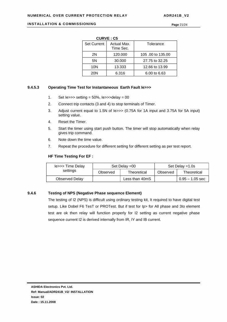
NUMERICAL OVER CURRENT PROTECTION RELAY ADR241B_V2 INSTALLATION & COMMISSIONING
ASHIDA Electronics Pvt. Ltd. Ref: Manual/ADR241B_V2/ INSTALLATION Issue: 02 Date : 15.11.2008
Page 21/24
CURVE : C5
Set Current Actual Max. Time Sec.
Tolerance
2N 120.000 105 .00 to 135.00 5N 30.000 27.75 to 32.25
10N 13.333 12.66 to 13.99 20N 6.316 6.00 to 6.63
9.4.5.3 Operating Time Test for Instantaneous Earth Fault Ie>>>
1. Set Ie>>> setting = 50%, Ie>>>delay = 00
2. Connect trip contacts (3 and 4) to stop terminals of Timer.
3. Adjust current equal to 1.5N of Ie>>> (0.75A for 1A input and 3.75A for 5A input) setting value.
4. Reset the Timer.
5. Start the timer using start push button. The timer will stop automatically when relay gives trip command.
6. Note down the time value.
7. Repeat the procedure for different setting for different setting as per test report.
HF Time Testing For EF :
Set Delay =00 Set Delay =1.0s Ie>>> Time Delay settings Observed Theoretical Observed Theoretical
Observed Delay Less than 40mS 0.95 – 1.05 sec 9.4.6 Testing of NPS (Negative Phase sequence Element)
The testing of I2 (NPS) is difficult using ordinary testing kit, It required to have digital test
setup. Like Dobel F6 TesT or PROTest. But if test for Ip> for All phase and 3Io element
test are ok then relay will function properly for I2 setting as current negative phase
sequence current I2 is derived internally from IR, IY and IB current.

NUMERICAL OVER CURRENT PROTECTION RELAY ADR241B_V2 INSTALLATION & COMMISSIONING
ASHIDA Electronics Pvt. Ltd. Ref: Manual/ADR241B_V2/ INSTALLATION Issue: 02 Date : 15.11.2008
Page 22/24
9.4.7 Testing Of Annunciation For Both O/C and EF
1. In Relay/LED configuration menu configure relay and Led as below.
Relay Configuration LED Configuration Relay Relay
Configuration Setting
Assign Function
LED Relay Configuration
Setting
Assign Function
RL1 A 0020 R>> LED5 GREEN A 0020 R>> RL1 B 8000 HR LED5 GREEN B 8000 HR RL2 A 0040 Y>> LED5 RED A 0040 Y>> RL2 B 8000 HR LED5 RED B 8000 HR RL3 A 0080 B>> LED6 GREEN A 0080 B>> RL3 B 8000 HR LED6 GREEN B 8000 HR RL4 A 0100 E>> LED6 RED A 0100 E>> RL4 B 8000 HR LED6 RED B 8000 HR RL5 A 0800 R>>> LED7 GREEN A 0800 R>>> RL5 B 8000 HR LED7 GREEN B 8000 HR
LED7 RED A 1000 Y>>> LED7 RED B 8000 HR
2. Ip>> =100%, Ip>> TMS = 0x0.02 & Ip>>>=100% , IP>>> Delay =00.00
3. Connect R CT terminal to current injector.
4. Now start increasing the current using VI control (Variac) and observe the pickup indication of the relay.
5. When the injected current crosses Ip>> % relay Pickup led will glow indicating relay pick-up condition. The relay gives trip signal. At the same time relay RL1 will operate and LED L5 GREEN will glow . Same will be reset manually as per configuration.
6. Follow the same procedure for every condition given above.
7. The result will found as per chart given below.
configuration RL1 RL2 RL3 RL4 RL5 L5 GREEN
L5 RED
L6 GREEN
L6 RED
L7 GREEN
L7 RED
R>> ON OFF OFF OFF OFF ON OFF OFF OFF OFF OFF
Y>> OFF ON OFF OFF OFF OFF ON OFF OFF OFF OFF
B>> OFF OFF ON OFF OFF OFF OFF ON OFF OFF OFF
E>> OFF OFF OFF ON OFF OFF OFF OFF ON OFF OFF
R>>> OFF OFF OFF OFF ON OFF OFF OFF OFF ON OFF
Y>>> OFF OFF OFF OFF OFF OFF OFF OFF OFF OFF ON

NUMERICAL OVER CURRENT PROTECTION RELAY ADR241B_V2 INSTALLATION & COMMISSIONING
ASHIDA Electronics Pvt. Ltd. Ref: Manual/ADR241B_V2/ INSTALLATION Issue: 02 Date : 15.11.2008
Page 23/24
9.5 Other Functional Test • Key functions: ______________
• HF Time Test (Should be <40ms at 2 times of HF settings ) : ______ .
• Trip Relay contacts: _______________.
• BF Timing Test : _______________
• BF Relay contacts : ______________
• Relay R1 to R5 Contacts : ________________
• Status S1 to S5 :_________________
• Status T1 & T2 : ____________
• Communication Test 1) RS 232 : _________ 2) RS 485 : __________
• Back Terminal Connection: _______________________________.
• Insulation test: __________________MΩ @ 1000VDC.
• H.V. Test: @ 2000VAC between all Terminals and body for 60 Sec. _____________.
• Conclusion: ________________________________________________.
Tested By Checked By (QC)
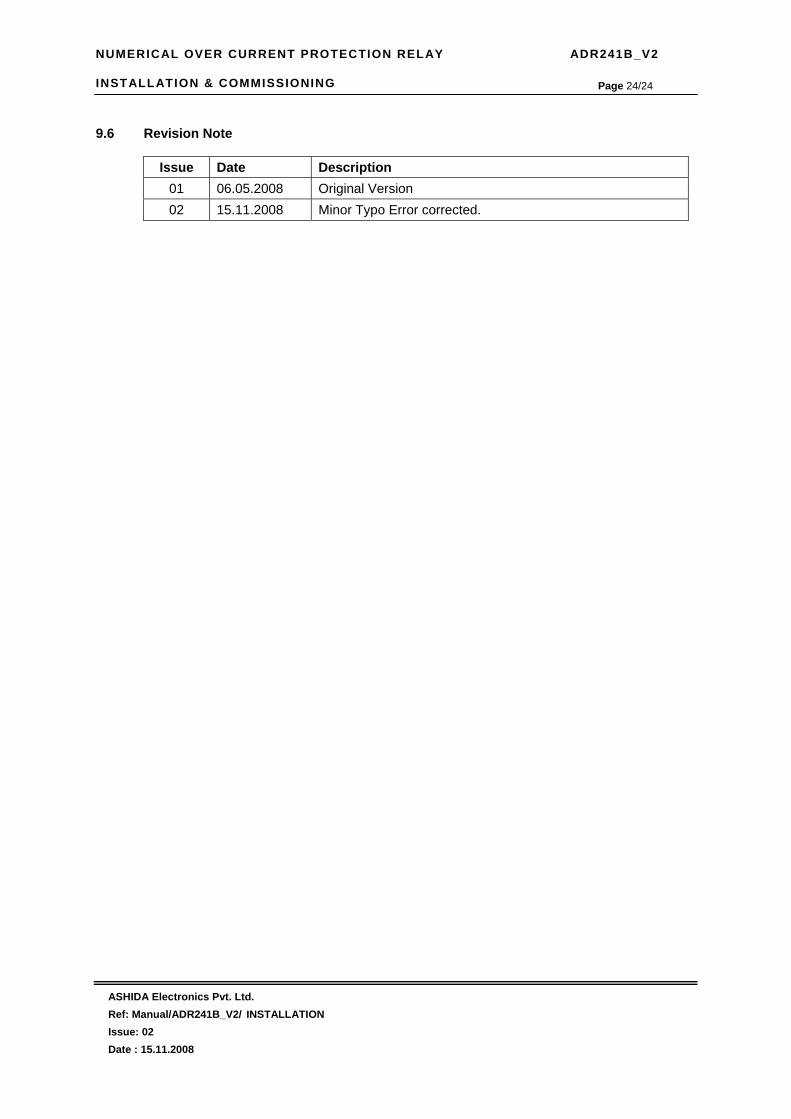
NUMERICAL OVER CURRENT PROTECTION RELAY ADR241B_V2 INSTALLATION & COMMISSIONING
ASHIDA Electronics Pvt. Ltd. Ref: Manual/ADR241B_V2/ INSTALLATION Issue: 02 Date : 15.11.2008
Page 24/24
9.6 Revision Note
Issue Date Description 01 06.05.2008 Original Version 02 15.11.2008 Minor Typo Error corrected.

NUMERICAL OVER CURRENT PROTECTION RELAY ADR241B_V2 PERIODIC TESTING
ASHIDA Electronics Pvt. Ltd. Ref: Manual/ADR241B_V2/ PERIODIC TESTING Issue: 02 Date : 15.11..2008
Page 1/16
PERIODIC RELAY
TESTING

NUMERICAL OVER CURRENT PROTECTION RELAY ADR241B_V2 PERIODIC TESTING
ASHIDA Electronics Pvt. Ltd. Ref: Manual/ADR241B_V2/ PERIODIC TESTING Issue: 02 Date : 15.11..2008
Page 2/16
CONTENTS
10 Periodic Testing 3
10.1 Trip Test 3
10.2 Functional Test 3
10.3 Testing of Relay 3
10.3.1 Relay Calibration 3
10.3.2 Diagram for Pickup and Timing Test 5
10.3.3 Testing of Over Current Protection 6
10.3.3.1 Pickup Test for Over Current 6
10.3.3.2 IDMT Time Test for Over Current 6
10.3.3.3 Testing of HF Pickup for Over Current Test 8
10.3.3.4 Operating Time test of HF for Over Current 9
10.3.4 Testing Of Earth Fault Current Protection 9
10.3.4.1 Testing of 3IO element 9
10.3.4.2 IDMT test for 3IO>> 10
10.3.4.3 Operating time test of HF for 3IO 11
10.3.4.4 Testing of EF element 12
10.3.4.5 IDMT time test for Ie >> 12
10.3.4.6 Operating Time test of HF for EF 14
10.3.4.7 Testing of NPS 14
10.3.5 Testing Of Annunciation For Both O/C and EF 14
10.3.6 Other functional tests 15
10.4 Revision Note 16

NUMERICAL OVER CURRENT PROTECTION RELAY ADR241B_V2 PERIODIC TESTING
ASHIDA Electronics Pvt. Ltd. Ref: Manual/ADR241B_V2/ PERIODIC TESTING Issue: 02 Date : 15.11..2008
Page 3/16
10 Periodic Testing As ADR241B_V2 is a numerical relay which is designed through the latest DSP technology and having self supervision function it is not necessary to test relay
completely. To conduct periodic testing a short testing is also sufficient to confirm relays functionality.
10.1. Trip Test
By pushing ‘Test’ push button relay hardware can tested as it will execute trip command &
records existing load current value in fault memory. In fault record flag indication is not there
its means it was a trip test conduct.
10.2. Functional Test
The relay can be tested in following way (External Test Report ADR241B_V2) 10.3. Testing of Relay 10.3.1. Relay Calibration
Before conducting actual test confirm relay calibration by following method. • Connect ADR 241B_V2 relay to current injector and timer as shown in diagram.
• Following chart shows terminal numbers of 1A / 5A CT connections.
Phase 1A 5A R C3, C4 C5, C6 Y C7, C8 C9, C10 B C11, C12 C13, C14
EF C15, C16 C17, C18
• Connect R CT terminals as per the chart.
• Adjust rated CT Secondary Current 1A/5A. Observe the current value from measurement
menu. The actual current should match with relay display.
• Adjust trimpot if it shows difference in actual and standard source. Refer following table
for calibration.
Phase Trimpot R P1 Y P2 B P3
EF P4
• Repeat the same procedure for other element.
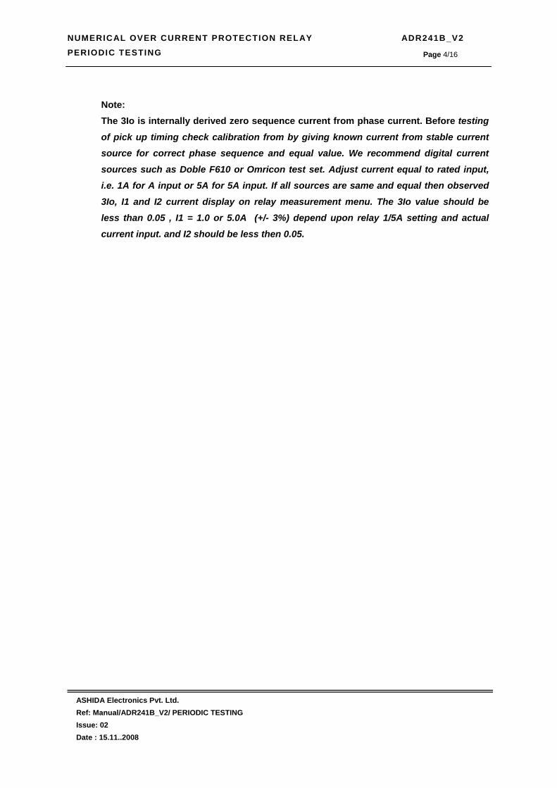
NUMERICAL OVER CURRENT PROTECTION RELAY ADR241B_V2 PERIODIC TESTING
ASHIDA Electronics Pvt. Ltd. Ref: Manual/ADR241B_V2/ PERIODIC TESTING Issue: 02 Date : 15.11..2008
Page 4/16
Note: The 3Io is internally derived zero sequence current from phase current. Before testing
of pick up timing check calibration from by giving known current from stable current source for correct phase sequence and equal value. We recommend digital current
sources such as Doble F610 or Omricon test set. Adjust current equal to rated input, i.e. 1A for A input or 5A for 5A input. If all sources are same and equal then observed
3Io, I1 and I2 current display on relay measurement menu. The 3Io value should be less than 0.05 , I1 = 1.0 or 5.0A (+/- 3%) depend upon relay 1/5A setting and actual
current input. and I2 should be less then 0.05.


NUMERICAL OVER CURRENT PROTECTION RELAY ADR241B_V2 PERIODIC TESTING
ASHIDA Electronics Pvt. Ltd. Ref: Manual/ADR241B_V2/ PERIODIC TESTING Issue: 02 Date : 15.11..2008
Page 6/16
10.3.3. TESTING OF OVER CURRENT PROTECTION 10.3.3.1. Pickup Test for O/C :
1. Connect ADR 241B_V2 relay to current injector and timer as shown in diagram.
2. Select IP>> =50%,100%, and 200% as per table, IP>> TMS =x0.02
3. Switch on current injector and inject the current to relay.
4. Now start increasing the current using VI control (Variac) and observe the pickup indication of the relay.
5. When the injected current crosses IP>> % relay Pickup led will glow indicating relay pick-up condition. The relay gives trip signal. Note down this current value as pick value of relay.
6. At the same time the relay latches the fault in the current buffer.
7. Read that current fault and note down the trip current value.
8. Repeat the procedure for different pickup setting for different phases as per test report.
Pick-up Test (IN AMPS.)
IP>> % R Phase Y Phase B Phase Limit value(amp)
1A 5A 1A 5A 1A 5A 1A 5A Min Max Min Max 50% 0.5 0.55 2.0 2.75 100% 1.0 1.1 5.0 5.5 200% 2.0 2.2 10.0 11
Result : Pickup accuracy was found within _______________ (1.1 Time of set value)
10.3.3.2. IDMT Time Test for O/C :
1. Set IP>> = and ip>> TMS as per table.
2. Connect trip contacts (3 and 4) to stop terminals of Timer.
3. Adjust current to required value as per test report.
4. Reset the Timer.
5. Start the timer using start push button. The timer will stop automatically when relay gives trip command.
6. Note down the time value.
7. Repeat the procedure for different setting for different phases as per test report.

NUMERICAL OVER CURRENT PROTECTION RELAY ADR241B_V2 PERIODIC TESTING
ASHIDA Electronics Pvt. Ltd. Ref: Manual/ADR241B_V2/ PERIODIC TESTING Issue: 02 Date : 15.11..2008
Page 7/16
Operating Time Test Setting Ip>> = 100% TMS = x 1.0 Note : You can use only one CT input and Operating curves which is relevant to your requirement
Set Current at Delay in Sec. For 1A For 5A C1 C2 C3 C4 C5
2N 2A 10A 5N 5A 25A
R Phase
10N 10A 50A 2N 2A 10A 5N 5A 25A
Y Phase
10N 10A 50A 2N 2A 10A 5N 5A 25A
B Phase
10N 10A 50A Setting Ip>> = 100% TMS = x 0.1 Note : Here all the timing should be 1/10 of about observed timing
Set Current at Delay in Sec. For 1A For 5A C1 C2 C3 C4 C5
2N 2A 10A 5N 5A 25A
R Phase
10N 10A 50A 2N 2A 10A 5N 5A 25A
Y Phase
10N 10A 50A 2N 2A 10A 5N 5A 25A
B Phase
10N 10A 50A (Operating time should as per curve as per following table)
C1 : Reading By Curve 10N = 3 Sec. C2 = Reading By Curve 10 = 1.3 Sec. C3 : Reading By Curve 10N = 1.5 Sec. C4 = Reading By Curve 10N = 0.8 Sec. C5 : Reading By Curve 10N = 13.3 Sec.
CURVE : C1 CURVE : C2
Set Current
Actual Max. Time Sec.
Tolerance Set Current
Actual Max. Time Sec.
Tolerance
2N 10.128 8.86 to 11.39 2N 4.389 3.84 to 4.93 5N 4.322 3.99 to 4.64 5N 1.873 1.73 to 2.01 10N 3.000 2.85 to 3.15 10N 1.300 1.23 to 1.36 20N 2.290 2.17 to 2.40
20N 0.992 0.94 to 1.04

NUMERICAL OVER CURRENT PROTECTION RELAY ADR241B_V2 PERIODIC TESTING
ASHIDA Electronics Pvt. Ltd. Ref: Manual/ADR241B_V2/ PERIODIC TESTING Issue: 02 Date : 15.11..2008
Page 8/16
CURVE : C3 CURVE : C4 Set
Current Actual Max. Time Sec.
Tolerance Set Current
Actual Max. Time Sec.
Tolerance
2N 13.500 11.81 to 15.18 2N 26.667 23.33 to 30.00 5N 3.375 3.12 to 3.62 5N 3.333 3.08 to 3.58 10N 1.500 1.42 to 1.57 10N 0.808 0.76 to 0.84 20N 0.711 0.67 to 0.74
20N 0.201 0.19 to 0.21 CURVE : C5
Set Current Actual Max. Time Sec.
Tolerance
2N 120.000 105 .00 to 135.00 5N 30.000 27.75 to 32.25
10N 13.333 12.66 to 13.99 20N 6.316 6.00 to 6.63
10.3.3.3. Testing of HF Pick-up for O/C Test
1. Set IP>>> = 200%, IP>>> delay = 0.
2. Start increasing the current using variac when it crosses IP>>> % settings the relay gives trip signal and the timer will stop.
3. The unit latches the fault current and will display message as follows:
IP> : IP>> : TC : 0026 IP>>> : R
R = 10.00 Y = 00.10 B = 00.10 N = 000.0 Date : 01/09/05 Time : 12:04:33:034
4. Note down the current value. At which relay trip.
5. Repeat the procedure for different setting as per test report.
H.F. Test : [ Amp.]
For 1 A For 5 A IP>>> % 200% (2A) 200%(10) R (Amps) Y (Amps) B (Amps)
The actual value should be with in +/- 10% setting

NUMERICAL OVER CURRENT PROTECTION RELAY ADR241B_V2 PERIODIC TESTING
ASHIDA Electronics Pvt. Ltd. Ref: Manual/ADR241B_V2/ PERIODIC TESTING Issue: 02 Date : 15.11..2008
Page 9/16
10.3.3.4. Operating Time test of HF for O/C
1. Set IP>>> setting = 100%, IP>>>delay = 00
2. Connect trip contacts (3 and 4) to stop terminals of Timer.
3. Adjust current equal to 1.5N of IP>>> (1.5A for 1A input and 7.5A for 5A input) setting value.
4. Reset the Timer.
5. Start the timer using start push button. The timer will stop automatically when relay gives trip command.
6. Note down the time value.
7. Repeat the procedure for different setting for different phases as per test report.
HF Time Testing For O/C :
Set Delay =00 Set Delay =1.0s IP>>> Time Delay settings Observed Theoretical Observe Theoretical
Observed Delay Less than 40mS 0.95 – 1.05 sec
10.3.4. TESTING OF EARTH FAULT CURRENT PROTECTION 10.3.4.1. Testing of 3Io element
Note: The 3Io is internally derived zero sequence current from phase current. Before
testing of pick up timing check calibration from by giving known current from
stable current source for correct phase sequence and equal value. We recommend digital current sources such as Doble F610 or Omricon test set. Adjust current
equal to rated input, i.e. 1A for A input or 5A for 5A input. If all sources are same and equal then observed 3Io, I1 and I2 current display on relay measurement menu.
The 3Io value should be less than 0.05 , I1 = 1.0 or 5.0A (+/- 3%) depend upon relay 1/5A setting and actual current input. and I2 should be less then 0.05.
1. Connect to R Phase CT input terminal of ADR 241B_V2 relay to current injector and timer as shown in diagram.
2. Select 3Io>> =10%, 3Io>> TMS =x0.02
3. Switch on current injector and inject the current to relay.
4. Now start increasing the current using VI control (Variac) and observe the pickup indication of the relay.
5. When the injected current crosses 3Io>> % relay Pickup led will glow indicating relay pick-up condition. The relay gives trip signal. Note down this current value as pick value of relay.

NUMERICAL OVER CURRENT PROTECTION RELAY ADR241B_V2 PERIODIC TESTING
ASHIDA Electronics Pvt. Ltd. Ref: Manual/ADR241B_V2/ PERIODIC TESTING Issue: 02 Date : 15.11..2008
Page 10/16
6. Read that current fault and note down the trip current value.
7. Repeat the procedure for different pickup setting for different phases as per test report.
Pick-up Test (IN AMPS.)
3Io>> % R Phase Limit value(amp)
1A 5A 1A 5A Min Max Min Max
10% 0.1 0.12 0.5 0.55 50% 0.5 0.55 2.5 2.75
100% 1.0 1.2 10.0 11.0
Result : Pickup accuracy was found within _______________ (1.1 Time of set value) 10.3.4.2. IDMT Time Test for 3Io>>
1. Set 3Io>> = and 3Io>> TMS as per table.
2. Connect trip contacts (3 and 4) to stop terminals of Timer.
3. Adjust current to required value as per test report.
4. Reset the Timer.
5. Start the timer using start push button. The timer will stop automatically when relay gives trip command.
6. Note down the time value.
7. Repeat the procedure for different setting. Operating Time Test
Setting 3Io>> = 50% 3Io> , Ip> and Ip>> = OFF TMS = x 1.0 Note : You can use only one CT input and Operating curves which is relevant to your requirement
Set Current at Delay in Sec. For 1A For 5A C1 C2 C3 C4 C5
2N 1A 5A 5N 2.5A 7.5A
R Phase
10N 5A 25A Setting 3Io>> = 100% 3Io> , Ip> and Ip>> = OFF TMS = x 0.1 Note : Here all the timing should be 1/10 of about observed timing
Set Current at Delay in Sec. For 1A For 5A C1 C2 C3 C4 C5
2N 1A 5A 5N 2.5A 7.5A
R Phase
10N 5A 25A

NUMERICAL OVER CURRENT PROTECTION RELAY ADR241B_V2 PERIODIC TESTING
ASHIDA Electronics Pvt. Ltd. Ref: Manual/ADR241B_V2/ PERIODIC TESTING Issue: 02 Date : 15.11..2008
Page 11/16
(Operating time should as per curve as per following table)
C1: Reading by Curve 10N = 3 Sec. C2 = Reading by Curve 10 = 1.3 Sec. C3: Reading by Curve 10N = 1.5 Sec. C4 = Reading by Curve 10N = 0.8 Sec. C5: Reading by Curve 10N = 13.3 Sec.
CURVE: C1 CURVE: C2
Set Current
Actual Max. Time Sec.
Tolerance Set Current
Actual Max. Time Sec.
Tolerance
2N 10.128 8.86 to 11.39 2N 4.389 3.84 to 4.93 5N 4.322 3.99 to 4.64 5N 1.873 1.73 to 2.01 10N 3.000 2.85 to 3.15 10N 1.300 1.23 to 1.36 20N 2.290 2.17 to 2.40
20N 0.992 0.94 to 1.04
CURVE: C3 CURVE: C4 Set
Current Actual Max. Time Sec.
Tolerance Set Current
Actual Max. Time Sec.
Tolerance
2N 13.500 11.81 to 15.18 2N 26.667 23.33 to 30.00 5N 3.375 3.12 to 3.62 5N 3.333 3.08 to 3.58 10N 1.500 1.42 to 1.57 10N 0.808 0.76 to 0.84 20N 0.711 0.67 to 0.74
20N 0.201 0.19 to 0.21 CURVE: C5
Set Current Actual Max. Time Sec.
Tolerance
2N 120.000 105 .00 to 135.00 5N 30.000 27.75 to 32.25
10N 13.333 12.66 to 13.99 20N 6.316 6.00 to 6.63
10.3.4.3. Operating Time test of HF for CIO
1. Set CIO>>> setting = 50%, CIO>>>delay = 00
2. Connect trip contacts (3 and 4) to stop terminals of Timer.
3. Adjust current equal to 1.5N of CIO>>> (0.75A for 1A input and 3.75A for 5A input) setting value.
4. Reset the Timer.
5. Start the timer using start push button. The timer will stop automatically when relay gives trip command.
6. Note down the time value.
7. Repeat the procedure for different setting for different setting as per test report.

NUMERICAL OVER CURRENT PROTECTION RELAY ADR241B_V2 PERIODIC TESTING
ASHIDA Electronics Pvt. Ltd. Ref: Manual/ADR241B_V2/ PERIODIC TESTING Issue: 02 Date : 15.11..2008
Page 12/16
HF Time Testing For CIO:
Set Delay =00 Set Delay =1.0s CIO>>> Time Delay settings Observed Theoretical Observe Theoretical
Observed Delay Less than 40mS 0.95 – 1.05 sec
10.3.4.4. Testing of EF element
Note: The Ie externally measure the EF and this element can be used as additional EF like
REF etc
1. Connect to EF CT input terminal of ADR 241B_V2 relay to current injector and timer as shown in diagram.
2. Select Ie>> =10%, Ie>> TMS =x0.02
3. Switch on current injector and inject the current to relay.
4. Now start increasing the current using VI control (Variac) and observe the pickup indication of the relay.
5. When the injected current crosses Ie>> % relay Pickup led will glow indicating relay pick-up condition. The relay gives trip signal. Note down this current value as pick value of relay.
6. Read that current fault and note down the trip current value.
7. Repeat the procedure for different pickup setting for different phases as per test report.
Pick-up Test (IN AMPS.)
Ie>> % EF input Limit value(amp)
1A 5A 1A 5A Min Max Min Max
10% 0.1 0.12 0.5 0.55 50% 0.5 0.55 2.5 2.75 80% 0.8 0.88 4.0 4.44
Result : Pickup accuracy was found within _______________ (1.1 Time of set value)
10.3.4.5. IDMT Time Test for Ie>>
1. Set Ie>> = and Ie>> TMS as per table.
2. Connect trip contacts (3 and 4) to stop terminals of Timer.
3. Adjust current to required value as per test report.
4. Reset the Timer.
5. Start the timer using start push button. The timer will stop automatically when relay gives trip command.
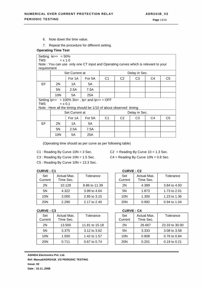
NUMERICAL OVER CURRENT PROTECTION RELAY ADR241B_V2 PERIODIC TESTING
ASHIDA Electronics Pvt. Ltd. Ref: Manual/ADR241B_V2/ PERIODIC TESTING Issue: 02 Date : 15.11..2008
Page 13/16
6. Note down the time value.
7. Repeat the procedure for different setting. Operating Time Test
Setting Ie>> = 50% TMS = x 1.0 Note : You can use only one CT input and Operating curves which is relevant to your requirement
Set Current at Delay in Sec. For 1A For 5A C1 C2 C3 C4 C5
2N 1A 5A 5N 2.5A 7.5A
EF
10N 5A 25A Setting Ip>> = 100% 3Io> , Ip> and Ip>> = OFF TMS = x 0.1 Note : Here all the timing should be 1/10 of about observed timing
Set Current at Delay in Sec. For 1A For 5A C1 C2 C3 C4 C5
2N 1A 5A 5N 2.5A 7.5A
EF
10N 5A 25A
(Operating time should as per curve as per following table)
C1 : Reading By Curve 10N = 3 Sec. C2 = Reading By Curve 10 = 1.3 Sec. C3 : Reading By Curve 10N = 1.5 Sec. C4 = Reading By Curve 10N = 0.8 Sec. C5 : Reading By Curve 10N = 13.3 Sec.
CURVE : C1 CURVE : C2
Set Current
Actual Max. Time Sec.
Tolerance Set Current
Actual Max. Time Sec.
Tolerance
2N 10.128 8.86 to 11.39 2N 4.389 3.84 to 4.93 5N 4.322 3.99 to 4.64 5N 1.873 1.73 to 2.01 10N 3.000 2.85 to 3.15 10N 1.300 1.23 to 1.36 20N 2.290 2.17 to 2.40
20N 0.992 0.94 to 1.04
CURVE : C3 CURVE : C4 Set
Current Actual Max. Time Sec.
Tolerance Set Current
Actual Max. Time Sec.
Tolerance
2N 13.500 11.81 to 15.18 2N 26.667 23.33 to 30.00 5N 3.375 3.12 to 3.62 5N 3.333 3.08 to 3.58 10N 1.500 1.42 to 1.57 10N 0.808 0.76 to 0.84 20N 0.711 0.67 to 0.74
20N 0.201 0.19 to 0.21

NUMERICAL OVER CURRENT PROTECTION RELAY ADR241B_V2 PERIODIC TESTING
ASHIDA Electronics Pvt. Ltd. Ref: Manual/ADR241B_V2/ PERIODIC TESTING Issue: 02 Date : 15.11..2008
Page 14/16
CURVE : C5
Set Current Actual Max. Time Sec.
Tolerance
2N 120.000 105 .00 to 135.00 5N 30.000 27.75 to 32.25
10N 13.333 12.66 to 13.99 20N 6.316 6.00 to 6.63
10.3.4.6. Operating Time test of HF for EF
1. Set Ie>>> setting = 50%, Ie>>>delay = 00
2. Connect trip contacts (3 and 4) to stop terminals of Timer.
3. Adjust current equal to 1.5N of Ie>>> (0.75A for 1A input and 3.75A for 5A input) setting value.
4. Reset the Timer.
5. Start the timer using start push button. The timer will stop automatically when relay gives trip command.
6. Note down the time value.
7. Repeat the procedure for different setting for different setting as per test report.
HF Time Testing For EF :
Set Delay =00 Set Delay =1.0s Ie>>> Time Delay settings Observed Theoretical Observed Theoretical
Observed Delay Less than 40mS 0.95 – 1.05 sec 10.3.4.7. Testing of NPS (Negative Phase sequence Element)
The testing of I2 (NPS) is difficult using ordinary testing kit, It required to have digital test
setup. Like Dobel F6TesT or PROTest. But if test for Ip> for All phase and 3Io element
test are ok then relay will function properly for I2 setting as current negative phase
sequence current I2 is derived internally from IR, IY and IB current.
10.3.5 Testing Of Annunciation For Both O/C and EF
1. In Relay/LED configuration menu configure relay and Led as below.
Relay Led Setting RL1 L5 GREEN IP>R RL2 L5 RED IP>Y RL3 L6 GREEN IP>B RL4 L6 RED IE>E RL5 L7 GREEN IP>>R

NUMERICAL OVER CURRENT PROTECTION RELAY ADR241B_V2 PERIODIC TESTING
ASHIDA Electronics Pvt. Ltd. Ref: Manual/ADR241B_V2/ PERIODIC TESTING Issue: 02 Date : 15.11..2008
Page 15/16
2. Select Ip> =50%, Ip>TMS =x0.01 Ip>> 100%, Ip>> TMS = 0x0.02
3. Connect R CT terminal to current injector.
4. Now start increasing the current using VI control (Variac) and observe the pickup indication of the relay.
5. When the injected current crosses Ip>> % relay Pickup led will glow indicating relay pick-up condition. The relay gives trip signal. At the same time relay RL1 will operate and LED L5 GREEN will glow.
6. Follow the same procedure for every condition given above.
7. The result will found as per chart given below.
configuration RL1 RL2 RL3 RL4 RL5 L5 GREEN
L5 RED
L6 GREEN
L6 RED
L7 GREEN
L7 RED
IP>R ON OFF OFF OFF OFF ON OFF OFF OFF OFF OFF
IP>Y OFF ON OFF OFF OFF OFF ON OFF OFF OFF OFF
IP>B OFF OFF ON OFF OFF OFF OFF ON OFF OFF OFF
IE>E OFF OFF OFF ON OFF OFF OFF OFF ON OFF OFF
IP>>R OFF OFF OFF OFF ON OFF OFF OFF OFF ON OFF
IP>>Y OFF OFF OFF OFF OFF OFF OFF OFF OFF OFF ON
10.3.6 Other Functional Test • Key functions: ______________
• HF Time Test (Should be <40ms at 2 times of HF settings ) : ______ .
• Trip Relay contacts: _______________.
• BF Timing Test : _______________
• BF Relay contacts : ______________
• Relay R1 to R5 Contacts : ________________
• Status S1 to S5 :_________________
• Status T1 & T2 : ____________
• Communication Test 1) RS 232 : _________ 2) RS 485 : __________
• Back Terminal Connection: _______________________________.
• Insulation test: __________________MΩ @ 1000VDC.
• H.V. Test: @ 2000VAC between all Terminals and body for 60 Sec. _____________.
• Conclusion: ________________________________________________.
Tested By Checked By (QC)

NUMERICAL OVER CURRENT PROTECTION RELAY ADR241B_V2 PERIODIC TESTING
ASHIDA Electronics Pvt. Ltd. Ref: Manual/ADR241B_V2/ PERIODIC TESTING Issue: 02 Date : 15.11..2008
Page 16/16
10.4 Revision Note
Issue Date Description
01 06.05.2008 Original Version 02 15.11.2008 Minor Typo Error Corrected

NUMERICAL OVER CURRENT PROTECTION RELAY ADR241B_V2 DETAILS OF INTERNAL CIRCUIT DIAGRAM
ASHIDA Electronics Pvt. Ltd. Ref: Manual/ADR241B_V2/ CIRCUIT DIAGRAM Issue: 02 Date : 15.11.2008
Page 1/4
Details of Internal Circuit Diagram
NUMERICAL OVER CURRENT PROTECTION RELAY ADR241B_V2 DETAILS OF INTERNAL CIRCUIT DIAGRAM
ASHIDA Electronics Pvt. Ltd. Ref: Manual/ADR241B_V2/ CIRCUIT DIAGRAM Issue: 02 Date : 15.11.2008
Page 2/4
CONTENTS
11.1 Detail of Internal Circuit diagram 3
11.2 Revision Note 4
NUMERICAL OVER CURRENT PROTECTION RELAY ADR241B_V2 DETAILS OF INTERNAL CIRCUIT DIAGRAM
ASHIDA Electronics Pvt. Ltd. Ref: Manual/ADR241B_V2/ CIRCUIT DIAGRAM Issue: 02 Date : 15.11.2008
Page 3/4
11.1 Detail of Internal Circuit diagram
Aditya series ADR241B relay having following assembly inside the relay. As per numerical
relay and having such a small box size, all printed circuit boards (PCB) are double sided and
designed using SMD component so it is not suggested to attend the relay on site by end user.
It can be attended by authorized service engineer of Ashida Electronic Pvt. Ltd. only to take
care of electronic component from electrostatic discharge.
1. Current transformer
2. SMPS Card
3. Back PCB contain power supply section and extra annunciation duty contact relay element.
4. Front PCB (Mother board) attached with front plate
5. Trip Contact relay element
6. Push button interface connected with front plate

NUMERICAL OVER CURRENT PROTECTION RELAY ADR241B_V2 DETAILS OF INTERNAL CIRCUIT DIAGRAM
ASHIDA Electronics Pvt. Ltd. Ref: Manual/ADR241B_V2/ CIRCUIT DIAGRAM Issue: 02 Date : 15.11.2008
Page 4/4
11.2 Revision Note
Issue Date Description 01 06.05.2008 Original Version 02 15.11.2008 Minor Typo Error Corrected

NUMERICAL OVER CURRENT PROTECTION RELAY ADR241B_V2 PROBLEMS OCCURRED
ASHIDA Electronics Pvt. Ltd. Ref: Manual/ADR241B_V2/ PROBLEMS OCCURRED Issue: 02 Date: 15.11.2008
Page 1/5
Problems Occurred/ Hardware Software
Revision

NUMERICAL OVER CURRENT PROTECTION RELAY ADR241B_V2 PROBLEMS OCCURRED
ASHIDA Electronics Pvt. Ltd. Ref: Manual/ADR241B_V2/ PROBLEMS OCCURRED Issue: 02 Date: 15.11.2008
Page 2/5
CONTENTS
12.1 Problems Occurred 3
12.2 Hardware / Software Revision 3
12.3 Revision Note 5

NUMERICAL OVER CURRENT PROTECTION RELAY ADR241B_V2 PROBLEMS OCCURRED
ASHIDA Electronics Pvt. Ltd. Ref: Manual/ADR241B_V2/ PROBLEMS OCCURRED Issue: 02 Date: 15.11.2008
Page 3/5
12.1 Problems Occurred
All Aditya series ADR241B are numerical relays designed with latest DSP technology and
having self supervision function which helps keep track on connected hardware and display
error code if any error is detected if problem is minor the relay automatically set default
setting and return back to protection function, following are error code which are
distinguished between major and minor .
ADR241B_V2
Sr. No. Error Code Error Name Minor Major Action Required
1. 01 Setting Error √ - Load default value
2. 02 EEPROM Error √ Contact Factory
3. 04 RTC Error √ - Relay May latch in correct timing internal battery is not working
4. 08 Ext.32KHz Crystal Error
√ - Contact Factory
5. 16 ADC Error - √ Contact Factory
6. 32 FRAM1 Error √ - Contact Factory
7. 64 FRAM2 Error √ - Contact Factory
12.2 Hardware / Software Revision
The revision is maintained in x.xx format 1st digit before decimal point is major version while two digits after decimal point are minor version
Sr. No.
Soft ware Version
Hard ware Revision
Date Remark
1 1.00 1.0 15/03/2008 Original Version 2 1.01 1.0 20/03/2008 CT Primary related Bug Fixed 3 1.02 1.0 20/03/2008 Power On display time reduce 4 1.03 &
1.04 1.0 20/03/2008 1. Reset Time of 500ms Added
2. Bug in CT primary calculation is removed
3. RPV factor in disturbance recorded is adjusted
5 1.05 & 1.06
1.0 24/03/2008 1. Parity setting in communication is added
2. Trip Contact HR/SR setting is added
3. Minor Bug in reset delay and DR record is fix

NUMERICAL OVER CURRENT PROTECTION RELAY ADR241B_V2 PROBLEMS OCCURRED
ASHIDA Electronics Pvt. Ltd. Ref: Manual/ADR241B_V2/ PROBLEMS OCCURRED Issue: 02 Date: 15.11.2008
Page 4/5
6 1.07 & 1.08 & 1.09
1.0 25/03/2008 1. BF logic Bypass during testing 2. BF Contact HR / SR setting added 3. Offset correction in EF input
7 2.00 1.0 08/04/2008 Relay measurement range improved, Calibration is shifted
8 2.01 1.0 22/04/2008 Internal EF i.e. 3Io setting added
9 2.02 1.0 02/05/2008 NPS setting added Di/Do updated
10 2.03 1.0 26/05/2008 Some minor bug in independent operation of stage1 and stage2 is corrected
For any Doubts / Difficulties please contact ASHIDA House, A-308 Road, No. 21, Wagle Industrial Estate Thane. 400 604 INDIA
Tel. : 91-22-25827524 / 25 / 26, 65771076 / 77 / 78 Fax. 91-22-25804262
Email: [email protected] [email protected]
Website : www.ashidaelectronics.com

NUMERICAL OVER CURRENT PROTECTION RELAY ADR241B_V2 PROBLEMS OCCURRED
ASHIDA Electronics Pvt. Ltd. Ref: Manual/ADR241B_V2/ PROBLEMS OCCURRED Issue: 02 Date: 15.11.2008
Page 5/5
12.3 Revision Note
Issue Date Description 01 06.05.2008 Original Version 02 15.11.2008 Minor Typo Error Corrected


![MAHALAKSHMI 2.pdfInduction type non-directional over current relay, Induction type directional over current relay & current differential relay. 2. Define energizing quantity. [AU/Nov/Dec/09/11]](https://img.pdfslide.us/doc/110x75/5b092d2c7f8b9ac90f8daa75/2pdfinduction-type-non-directional-over-current-relay-induction-type-directional.jpg)


![GROUND OVER CURRENT RELAY (EARTH FAULT RELAY)[50/51N]](https://img.pdfslide.us/doc/110x75/616a4f1111a7b741a35115fa/ground-over-current-relay-earth-fault-relay5051n.jpg)