Embed Size (px)
Citation preview

SHOTGUNUSER MANUAL
OVER & UNDER

User manual
BASIC SAFETY RULES ............................. 3
ASSEMBLY .............................................. 10
USE ......................................................... 13
DISASSEMBLY......................................... 18
MAINTENANCE ....................................... 20
ACCESSORIES AND ADJUSTMENTS.... 22
STORAGE ................................................ 38
WARRANTY ............................................. 38

C6A007 006
Warning, Caution and Notice headings are defined as follows:
This manual and its illustrations apply to the Series 690 shotgun.The references “left” or “right” always refer to the shotgun as shouldered by the user.
The contents of this manual are subject to change without notice.
1
OVER-AND-UNDERS
THE PURPOSE OF A WARNING IS TO DRAW ATTENTION TO A POTENTIALITY DANGEROUS SITUATION THAT COULD RESULT IN PERSONAL INJURY.
WARNING
A CAUTION concerns potential damage to the shotgun.
CAUTION
A NOTICE highlights important procedures and statements that require more emphasis than general text.
Notice

C6A007 006
2
OVER-AND-UNDERS
THIS MANUAL CONTAINS IMPORTANT WARNINGS THAT MUST BE UNDER-STOOD BEFORE USING THIS SHOTGUN. PLEASE RETAIN THIS COPY OF THE INSTRUCTION MANUAL FOR FUTURE REFERENCE. ANY TRANSFER OF THIS SHOTGUN SHOULD INCLUDE A COPY OF THIS MANUAL. IF YOU LEND, GIVE OR SELL THE SHOTGUN TO ANYONE, BE SURE THE INSTRUCTION MANUAL ACCOMPANIES IT AS A SAFETY AND OPERATIONAL REFERENCE.
WARNING
FIREARMS CAN BE DANGEROUS AND CAN POTENTIALLY CAUSE SERIOUS INJURY, DAMAGE TO PROPERTY OR DEATH, IF HANDLED IMPROPERLY. THE FOLLOWING SAFETY RULES ARE AN IMPORTANT REMINDER THAT SHOTGUN SAFETY IS YOUR RESPONSIBILITY.
WARNING
ALWAYS ENSURE THAT THE SAFETY IS ENGAGED UNTIL READY TO FIRE. CAREFULLY READ THE “SAFETY” PARAGRAPH IN THIS MANUAL BE-FORE USING THIS SHOTGUN.
WARNING
READ THE ENTIRE MANUAL CAREFULLY BEFORE USING THIS SHOTGUN. MAKE SURE THAT ANY PERSON USING OR HAVING ACCESS TO THIS SHOT-GUN READS AND UNDERSTANDS ALL OF THIS MANUAL PRIOR TO USE OR ACCESS. WE RECOMMEND THE USE OF ORIGINAL BERETTA SPARE PARTS AND AC-CESSORIES. THE USE OF OTHER MANUFACTURER’S SPARE PARTS AND ACCESSORIES COULD CAUSE MALFUNCTIONS AND/OR BREAKAGES THAT WILL NOT BE COVERED BY THE BERETTA WARRANTY.
WARNING

C6A007 006
3
OVER-AND-UNDERS
BASIC SAFETY RULES
1. NEVER POINT A FIREARM AT SOMETHING THAT IS NOT SAFE TO SHOOT.
Never let the muzzle of a firearm point at any part of your body or at another person. This is espe-cially important when loading or unloading the firearm. When you are shooting at a target, know what is behind it. Some bullets can travel over a mile. If you miss your target or if the bullet pene-trates the target, it is your responsibility to ensure that the shot does not cause un intended injury or damage.
2. ALWAYS TREAT A FIREARM AS IF IT WERE LOADED.
Never assume that a firearm is unloaded. The only certain way to ensure there are no cartridges in a firearm is to open the chamber and visually and physically examine the inside to see if a round is present. Removing or unloading the magazine will not guarantee that a firearm is unloaded or cannot fire. Firearms and rifles can be checked by cycling or removing all rounds and by then opening the chamber so that a visual inspection of the chamber for any remaining rounds can be made.

C6A007 006
4
OVER-AND-UNDERS
3. STORE YOUR FIREARM SO THAT CHILDREN CANNOT GAIN ACCESS TO IT.
It is your responsibility to ensure that children under the age of 18 or other un authoris-ed persons do not gain access to your firearm. To reduce the risk of accidents involv-ing children, unload your firearm, lock it, and store the ammunition in a separate locked location. Please note that devices intended to prevent accidents - for example, cable locks, chamber plugs, etc. - may not prevent use or misuse of your firearm by a determined person. Firearm storage in a steel gun safe may be more appropriate to reduce the likelihood of intentional misuse of a firearm by a child or unauthorised person.
4. NEVER SHOOT AT WATER OR AT A HARD SURFACE.
Shooting at the surface of water or at a rock or other hard surface increases the chance of ricochets or fragmentation of the bullet or shot, which can result in the projectile striking an unintended or peripheral target.
5. KNOW THE SAFETY FEATURES OF THE FIREARM YOU ARE USING, BUT REMEMBER: SAFETY DEVICES ARE NOT A SUBSTITUTE FOR SAFE HAN -D L ING PROCEDURES.
Never rely solely on a safety device to prevent an accident. It is imperative that you know and use the safety features of the particular firearm you are handling, but acci-dents can best be prevented by following the safe handling procedures described in these safety rules and elsewhere in the product manual. To further familiarise yourself with the proper use of this or other firearms, take a Firearms Safety Course taught by an expert in firearms use and safety procedures.

C6A007 006
5
OVER-AND-UNDERS
6. PROPERLY MAINTAIN YOUR FIREARM.
Store and carry your firearm so that dirt or lint does not accumulate in the working parts. Clean and oil your fire-arm, following the instructions provided in this manual, af-ter each use to prevent corrosion, damage to the barrel or accumulation of impurities that can prevent use of the fire-arm in an emergency. Always check the bore and cham-ber(s) prior to loading to ensure that they are clean and free from obstructions. Firing with an obstruction in the barrel or chamber can rupture the barrel and injure you or others nearby. In the event you hear an unusual noise when shoot-ing, stop firing immediately, engage the manual safety, and unload the firearm. Make sure the chamber and barrel are free from any obstruction, like a bullet blocked in-side the barrel due to defective or improper ammunition.
7. USE PROPER AMMUNITION.
Only use factory-loaded, new ammunition manufactured to industry specifications: CIP (Europe and elsewhere), SAAMI® (U.S.A.). Be certain that each round you use is in the proper calibre or gauge and type for the particular firearm. The calibre or gauge of the firearm is clearly marked on the barrels of firearms and on the slide or barrel of pistols. The use of reloaded or remanufactured ammunition can increase the likeli-hood of excessive cartridge pressures, case-head ruptures or other defects in the ammunition that can cause damage to your firearm and injury to yourself or others nearby.
8. ALWAYS WEAR PROTECTIVE GLASSES AND EARPLUGS WHEN SHOOTING.
The chance that gas, gunpowder or metal fragments will blow back and injure a shooter who is firing a gun is rare, but the injuries that can be sustained in such circumstances can be severe, including the possible loss of eyesight. A shooter must always wear impact-resistant shooting glasses when firing any firearm. Noise-reducing earplugs or headphones will reduce the risk of damage to hearing caused by pro-longed shooting activity.

C6A007 006
6
OVER-AND-UNDERS
9. NEVER CLIMB A TREE, FENCE OR OBSTRUCTION WITH A LOADED FIREARM.
Open and empty the chamber(s) of your firearm and en gage the manual safety before climbing or descending a tree or before climbing a fence or jumping over a ditch or other obstruction. Never pull or push a loaded firearm toward yourself or another person. Always unload a firearm, visual-ly and physically check to see that the magazine, load ing mechanism, and chamber are unloaded, and the action is open before handing it to another person. Never take a firearm from another person unless it is unloaded, visually and physically checked to confirm it is unloaded, and the action is open.
10. AVOID ALCOHOLIC BEVERAGES OR JUDGEMENT/REFLEX IMPAIRING MEDICATION WHEN SHOOTING.
Do not drink and shoot. If you take medication that can impair motor reactions or judgement, do not handle a fire-arm while you are under the influence of the medication.
11. NEVER TRANSPORT A LOADED FIREARM.
Unload a firearm before putting it in a vehicle (chamber emp-ty, magazine empty). Hunters and target shooters should load their firearm only at their destination, and only when they are ready to shoot. If you carry a firearm for self-protec-tion, leaving the chamber unloaded can reduce the chance of an unintentional discharge.

C6A007 006
7
OVER-AND-UNDERS
12. LEAD WARNING.
Discharging firearms in poorly ventilated areas, cleaning firearms, or handling am-munition may result in exposure to lead and other substances known to cause birth defects, reproductive harm, and other serious physical injury. Have adequate ventila-tion at all times. Wash hands thoroughly after exposure.
It is YOUR responsibility to know and abide by Federal, State and Local laws gov-erning the sale, transportation and use of firearms in your area.
Notice
THIS FIREARM HAS THE CAPABILITY TO TAKE YOUR LIFE OR THE LIFE OF SOMEONE ELSE!
ALWAYS BE EXTREMELY CAREFUL WITH YOUR FIREARM.
AN ACCIDENT IS ALMOST ALWAYS THE RESULT OF NOT FOLLOWING BASIC FIRE ARM SAFETY RULES.
BEFORE USING THE FIREARM OR CARRYING OUT ANY OPERATION IN THIS MANUAL, BE SURE TO FOLLOW THE BASIC SAFETY RULES CAREFULLY.
WARNING
The Manufacturer and/or its Local Official Distributors assume no responsibility for product malfunction, or for physical injury or property damage resulting wholly or partially from criminal or negligent use of the product, improper or careless handling, unauthorized modifications, use of defective, improper, handloaded, reloaded or remanufactured ammunition, customer abuse or neglect of the product, or other influences beyond manufacturer’s direct and immediate control.
In addition to the Basic Safety Rules, there are other Safety Rules pertaining to the loading, unloading, disassembly, assembly and use of this shotgun, located throughout this manual.
Notice
BERETTA ACCEPTS NO RESPONSIBILITY FOR INJURY OR PROPERTY DAMAGE CAUSED BY IMPROPER OR CARELESS HANDLING OF THE FIREARM OR BY INTENTIONAL OR CARELESS DISCHARGE OF THE FIREARM.
WARNING

C6A007 006
8
OVER-AND-UNDERS
OBSTRUCTION / CHOKE TUBES CONDITION CHECK Check the barrels to ensure there are no obstructions in the chamber and bore. This is extremely important because seri-ous injury can result to the user or to nearby persons if a cartridge is fired in an obstructed barrel or chamber.
Check the inside of the barrels prior to completely assembling the firearm and before use; if the firearm is already as-sembled the following procedure should be followed:
• Follow the instructions in the “Disas-sembly” section, page 18, and remove the barrels from the shotgun.
• After removing the barrels, look right through the barrels from the rear and make sure there are no obstructions, even minor ones.
• If an obstruction in the barrels is detect-ed, a competent gunsmith must remove the obstruction. Inspect again the shot-gun before it can be fired.
• Remount the barrels, following the in-structions set out in the “Assembly” section, page 10.
CHECKING THE CONDITION OF THE CHOKE TUBES
• Always check the appearance and cleaning of the choke tubes before us-ing the shotgun.
• Check correct tightness in the barrels with the spanner provided.
• Never use choke tubes that show signs of defects, warping or incrustation.
• Make sure that the choke tube inserted is appropriate for the intended use and shot type to be used (steel or lead).

C6A007 006
PARTS
OVER-AND-UNDERS
FIGURE 1
A butt plateB tipC stockD triggerE trigger guardF receiverG hinge pinH fore-endI barrelsJ muzzleK chokesL sightM top ribN drop at combO line of sightP length of pullQ drop at heelR fore-end catch leverS fore-end ironT top leverU safety/fire selectorV stock drop
CB
O
Q
T
U
P
A
R
GFE
H
D
I
M
JKL
N
S
V
1
9

CASE - FIG. 2
A barrel+fore-endB stock+receiverC Beretta snap caps (if provided)
D chokes+wrenchE special tools (if provided)F Beretta shotgun oil
ASSEMBLYASSEMBLY PROCEDURE
• Remove the shotgun parts from their protective covering (always dispose of these covers responsibly).
• Inspect the insides of the barrels, which must be clean and free from obstruc-tions.
• Use the fore-end catch lever (fig. 3).
• Turn the fore-end slightly and slide it forward (toward the muzzle) (fig. 4).
10
OVER-AND-UNDERS C6A007 006
3
4
A
F
EB
C D 2
Never insert the barrels into the re-ceiver if the fore-end is fitted onto the barrel assembly.
CAUTION
C6A007 006
11
OVER-AND-UNDERS
5
6
7
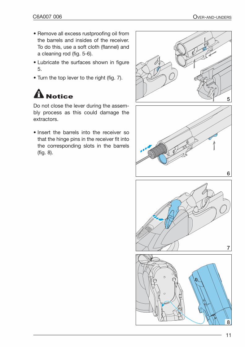
• Remove all excess rustproofing oil from the barrels and insides of the receiver. To do this, use a soft cloth (flannel) and a cleaning rod (fig. 5-6).
• Lubricate the surfaces shown in figure 5.
• Turn the top lever to the right (fig. 7).
• Insert the barrels into the receiver so that the hinge pins in the receiver fit into the corresponding slots in the barrels (fig. 8).
Do not close the lever during the assem-bly process as this could damage the extractors.
Notice
8

• Slowly and gently tilt the barrels up-ward, making sure that the extractor lugs are correctly inserted into the slots in the receiver (fig. 9).
• When the opening lever snaps into po-sition in the center, this means the bar-rels are locked in the receiver (fig. 10).
• Fit the fore-end on the barrels by hook-ing the fore-end iron onto the receiver (fig. 11).
• Turn the fore-end upward and firmly press it against the barrels to engage the barrel hook mechanism (fig. 12).
• The fore-end is only locked in place when the lever is aligned in its slot (fig. 13).
12
OVER-AND-UNDERS C6A007 006
13
CLACK
10
9
11
12

USE
AMMUNITION
• Beretta over-and-unders have 2” 3/4 (70 mm) or 3” (76 mm) chambers.
• On the side of the barrels, you will find the markings for the caliber and cham-ber (fig. 14).
• Every shotgun has been officially tested with special proof-test ammunition to verify the quality and strength of the material used.
13
OVER-AND-UNDERSC6A007 006
12 GA.2” 3/4 - 70 - 28”BERETTA - GARDONE V.T. - MADE IN ITALY
BERETTA CANNOT ACCEPT ANY RE-SPONSIBILITY FOR PHYSICAL INJU-RY OR PROPERTY DAMAGE CAUSED BY THE USE OF DEFECTIVE, IM-PROPER, HAND-LOADED, RE-LOAD-ED OR REMANUFACTURED AMMU-NITION. SERIOUS DAMAGE, INJURY AND EVEN DEATH CAN RESULT FROM THE USE OF INCORRECT AMMUNITION, EXCESSIVE CARTRIDGE PRESSURE OR BORE OBSTRUCTIONS. USE OF RELOADED AMMUNITION WILL VOID THE MANUFACTURER’S WARRANTY. ONLY USE HIGH-QUALITY, FACTO-RY-NEW AMMUNITION.
WARNING
NEVER FIRE CARTRIDGES THAT DO NOT COMPLY WITH THE MARKINGS ON THE BARRELS.
WARNING
ALWAYS USE CARTRIDGES WITH A LENGTH EQUAL TO OR LESS THAN THE LENGTH OF THE CHAMBER MARKED ON THE BARRELS.
WARNING
TO AVOID USING THE INCORRECT TYPE OF AMMUNITION, ALWAYS CHECK THE CHARACTERISTICS GIV-EN ON THE CARTRIDGE BOX AND ON THE CARTRIDGES THEMSELVES. MAKE SURE THAT YOU USE THE CA L-I BER AND LENGTH OF CARTRIDGE THAT ARE SUITABLE FOR YOUR SHOTGUN.
WARNING
TO AVOID SHOTGUN MALFUNC-TIONS, ALWAYS INSPECT EACH CARTRIDGE BEFORE INSERTING IT INTO THE CHAMBER. MAKE SURE THAT THE CASE HEADS ARE NOT DAMAGED OR MISSHAPEN AND THAT THERE ARE NO OTHER DENTS OR DEFECTS IN THE AMMU-NITION. THESE CHECKS ARE ALSO REQUIRED FOR FACTORY-NEW AM-MUNITION.
WARNING
14

14
OVER-AND-UNDERS C6A007 006
LOADING AND FIRING
WARNINGBEFORE LOADING THE FIREARM, YOU SHOULD MAKE SURE THAT YOU ARE FAMILIAR WITH THE FOL-LOWING LOADING AND UNLOADING OPERATIONS WITHOUT USING AM-MUNITION.
NEVER HANDLE A LOADED FIREARM UNTIL YOU ARE ABLE TO CONFI-DENTLY AND CORRECTLY CARRY OUT THESE PROCEDURES.
Always keep your finger away from the trigger if you do not intend to shoot.
The shooter and anyone in the vicinity should always wear safety glasses and ear protection during firearm use.
Particles of shot powder, lubricant or metal fragments may be projected back-ward and cause injury. Ear plugs or head-sets will reduce the risk of hearing dam-age from exposure to long periods of shoot ing.
Before any hunting or shooting session, disassemble your shotgun and make sure that the chokes are fitted, clean, tight and suitable for the ammunition.
STEEL SHOT
Beretta barrels and chokes for use with steel shot, have been designed to be used with factory-new cartridges loaded with steel shot and compliant to interna-tional standards.
Remanufactured or rebuilt cartridges can increase the probability of excess pres-sure, case head ruptures or other ammu-nition defects.
All Beretta barrels can fire “ordinary steel shot ammunitions” (CIP definition).
All barrels, currently made by Beretta, with removable chokes can fire “High Performance steel shot ammunitions” (CIP definition).
The use of High Performance steel shot ammunitions (CIP definition) with HP 0 (*) and 00 (**) chokes is strongly discour-aged, because it may cause unpredict-able wear of the chokes, with the conse-quent deterioration of the barrel’s ballistic performances.
Beretta advices against use of High Per-formance steel shot ammunitions (CIP definition) in barrels with fixed choke, as it could undermine shooting performances and accelerate gun's wear over the long period.
The best results are obtained with steel short cartridges when using open chokes (C0000/CL, 0000/IC, 000/M, S, SK).
Full choke constrictions (0/F, 00/IM) when using steel shot do not increase pattern density and they also distort the distribu-tion of the shot, speeding up choke wear and tear.

15
OVER-AND-UNDERSC6A007 006
Keep the barrels pointed in a safe direc-tion and:
• engage the safety by moving it back; the letter “S” must be fully visible (fig. 15);
• turn the top lever and tilt the barrels downward (fig. 16).
NoticeFor shotguns with “Automatic Safety”, the safety is automatically engaged when the top lever is turned to open the shot-gun.
• Inspect the insides of the barrels to make sure there are no obstructions; then proceed to load it.
• Load the correct caliber cartridges into the chamber (fig. 17).
• Close the shotgun and make sure that the top lever has clicked back into po-sition, as shown in figure 18.
WARNINGTHE MANUAL SAFETY IS A MECHAN-ICAL DEVICE AND DOES NOT RE-PLACE A RESPONSIBLE SHOTGUN USER.AT THIS POINT IN THE LOADING PRO-CESS, THE HAMMERS ARE COCKED AND THE FIREARM IS READY TO SHOOT. FOLLOW THE SAFETY PRO-CEDURES WITH CARE.
S
17
CLACK
18
S
15
S
16

BARREL SELECTOR
Shotguns with “selective single trigger” will fire first from the selected barrel when you pull the trigger:
• selector to the left = first barrel (bottom, fig. 19);
• selector to the right = second barrel (top, fig. 20).
• Push the safety slider forwards (letter “S” covered, fig. 21): when the trigger is pulled, it will fire the first shot.
• After firing the first shot, release the trigger all the way; the shotgun will au-tomatically prepare to fire the second shot without the need to use the selec-tor. Pull the trigger again and fire the sec ond shot.
For shotguns with “single trigger”, when the trigger is pulled, the first barrel (bot-tom) is fired and then the second (top).
For shotguns with “double trigger”, the front trigger fires the first barrel (bottom) and the rear trigger fires the second barrel (top).
WARNINGIF YOU PULL THE TRIGGER AND THE SHOTGUN DOES NOT FIRE, AIM THE BARRELS IN A SAFE DIRECTION AND ENGAGE THE SAFETY.WAIT AT LEAST 1 MINUTE, OPEN THE SHOTGUN AND THEN MANUALLY REMOVE THE CARTRIDGE THAT WAS NOT FIRED.
UNLOADING
• Aim the barrels in a safe direction and engage the safety (fig. 22).
16
OVER-AND-UNDERS C6A007 006
21
S
22
S
19
S
20

• Turn the top lever to the right and tilt the barrels downward (fig. 23).
CAUTIONWhen the shotgun is opened after shooting, the extractors will eject the spent shells and raise the unfired cartridges to make manual removal easier.
• Take out the unfired cartridges by hand (fig. 24).
DECOCKING THE HAMMERS
After unloading the shotgun and before putting it away, always decock the ham-mers to decompress the springs.
17
OVER-AND-UNDERSC6A007 006
SS
24 25
S
23
It is equally important not to decock the hammers by pulling the trigger on an un-loaded shotgun without snap-caps; the action could damage the firing pins.
To decock the hammers without damage to the firing pins, insert the special Beretta snap-caps (fig. 25) (available in gun stores). The snap-caps allow the shotgun to be “dry fired”.
• Load the shotgun as usual with the two snap-caps.
• Pull the trigger to decock the first ham-mer.
• Move the selector, pull the trigger and decock the second hammer.
If the shotgun has a “single trigger” or a “blocked selective trigger”, decock the hammer by tapping the butt with your hand and then pulling the trigger.
NoticeTilting the barrels down will automati-cally recock the hammers.To strip the shotgun WITHOUT RE-COCKING THE HAMMERS, follow the instructions in “Disassembly”, page 18.

• Pull the fore-end catch lever down (fig. 26).
• Turn the fore-end forward to remove it from the receiver (fig. 27).
• Turn the top lever to the right (fig. 28).
• Tilt the barrels downward, holding them firmly to stop them from sliding off the hinge pins completely and falling.
• Lift the barrels gently upward and out of the receiver (fig. 29). The top lever will still be open.
• If the shotgun is loaded with dummy cartridges (snap caps), remove them.
To return the shotgun to its case:
• fit the fore-end on the barrels (see page 12);
• keep the top lever turned all the way to the right and press the top lever plunger all the way, as shown in figure 30;
• release the top lever, keeping the plung-er pressed.
18
OVER-AND-UNDERS C6A007 006
27
26
S
28
S
29 30
DISASSEMBLY
ALWAYS MAKE SURE THAT THE SHOTGUN IS UNLOADED BEFORE BEGINNING DISASSEMBLY PROCE-DURES.
WARNING

STOCK REMOVAL - FIG. 31
A fastening screwsB butt plateC stock bolt (allen hex-head)D guide bushing (if fitted, this makes it
easier to insert the Allen key and to detach the stock from the receiver)
E crosshead screwdriverF Allen key
Procedure:
• loosen the two fastening screws “A” and take off the butt plate “B”;
• insert the Allen key into the bolt “C”;
• unscrew the bolt counterclockwise until the stock comes away completely from the receiver.
To refit the stock, follow these steps in reverse order.
19
OVER-AND-UNDERSC6A007 006
E
F
C
D
A
A
B
31
To prevent damage to the butt plate, we recommend applying petroleum jelly or grease to the screws “A” and the tip of the screwdriver “E”.
CAUTION

• At the end of a hunting or shotting session, clean the shotgun and make sure the chokes are properly tightened. Metal surfaces on shotguns without protective surface treatment need to be cleaned thoroughly and lubricated after every use to protect against rust.
• Use a cotton cloth soaked in Beretta gun cleaner and a cleaning rod to re-move firing residues from the barrels. Use a bronze brush if necessary.
• Always insert the cleaning rod into the cartridge chamber (fig. 32).
• Run a clean, dry cloth through the bores to remove detergent residues.
• Lightly oil the bores with Beretta gun oil on a clean cotton cloth.
• Clean the inner face of the receiver (es-pecially the area around the firing pin holes) and oil lightly (see figure 33).
20
OVER-AND-UNDERS C6A007 006
MAINTENANCE
ALWAYS MAKE SURE THAT THE SHOTGUN IS UNLOADED BEFORE COMMENCING ANY MAINTENANCE OPERATIONS.
WARNING
YOU ARE FULLY RESPONSIBLE FOR THE CORRECT MAINTENANCE OF YOUR SHOTGUN.
WARNING
32
33
NO
34
Never apply too much oil.A build up of oil will attract dirt and this can interfere with the shotgun’s operation and reliability.
CAUTION
Do not allow oil to enter the firing pin holes (fig. 34).
CAUTION

• Clean the surfaces shown in figure 35, and oil them lightly.
21
OVER-AND-UNDERSC6A007 006
The hinge pin area is a very important coupling area.
The receiver and fore-end iron are subject to very high loads and if not properly oiled, could cause seizing of parts or shotgun malfunctioning.
Always make sure these parts are lubricated, following the instructions provided.
Carefully clean the outer surfaces of the shotgun to remove all traces of dirt, sweat and fingerprints.
Apply a thin layer of gun oil (good quality) to the shotgun, using a soft cloth.
CAUTION
Before storing the shotgun, always check the conditions of the shotgun and case, which must be perfectly dry. Moisture and water can damage the shotgun.
CAUTION
EXCESS OIL OR GREASE CAN OB-STRUCT THE BORE, EVEN PARTIAL-LY; THIS MAKES FIRING VERY DAN-GEROUS AND CAN DAMAGE THE SHOTGUN AS WELL AS CAUSING SERIOUS INJURY TO THE SHOOTER AND BYSTANDERS.
WARNING
NEVER SPRAY OR APPLY OIL TO CARTRIDGES.
WARNING
Do not attempt to make repairs to your shotgun if you are not sufficiently experi-enced or trained. Never make alterations or adjustments to any part of the shotgun and only use original Beretta spare parts. Any alteration or intervention necessary for the shotgun to function must be car-ried out by the manufacturer or by a qualified person.
Notice
35

ACCESSORIES AND ADJUSTMENTS
The accessories and adjustments de-scribed below may apply to just some of the shotgun models in this manual and therefore, may not be provided as stand-ard.
CHOKES
22
OVER-AND-UNDERS C6A007 006
HP TAPERED
HP TAPERED
36
ALWAYS MAKE CERTAIN THAT THE SHOTGUN IS UNLOADED BEFORE MAKING ANY ADJUSTMENTS.
WARNING
WHEN YOU BUY A NEW CHOKE OR USE A CHOKE NOT PROVIDED IN THE ORIGINAL PACKAGING OF THE SHOTGUN, ALWAYS MAKE SURE THAT THE WORDING PRINTED ON THE CHOKE IS THE SAME AS THAT ON THE CHOKE IN THE ORIGINAL PACKAGING.
THE BARRELS ARE OPTIMIZED TO BE FIRED WITH A SPECIFIC TYPE OF CHOKE.
FIRING WITH INCORRECT OR NON-BERETTA CHOKES CAN DAM-AGE THE BARREL AND BE DANGER-OUS.
WARNING
Choke type Barrel type
On sleeve (fig. 14) On tube (fig. 36)
Mobilchoke CALIBER
Optimachoke OB CALIBER
Optimachoke HP CALIBER
HP TAPERED
HP OB
OB HP CALIBER
On choke SP = Steel Proof - HP = High Performance
This wording on the chokes means the choke can be used to fire cartridges containing steel shot. The same choke, only if a Mobilchoke, can also fire high-performance steel shot HP, according to the barrel being used.
This wording on a choke means the choke can be used to fire cartridges containing steel shot and “high performance” HP steel shot, according to the barrel being used.
SP
HP

23
OVER-AND-UNDERSC6A007 006
BEFORE HUNTING OR SHOOTING, MAKE SURE THAT THE CHOKES ARE FITTED, CLEAN, COMPLETELY TIGHTENED, AND SUITABLE FOR THE AMMUNITION TO BE USED.
WARNING
DO NOT SHOOT WITH CHOKE BAR-RELS WITHOUT USING CHOKE TUBES.
SHOOTING WITHOUT CHOKE TUBES IS DANGEROUS BECAUSE FRAG-MENTS OR LEAD RESIDUES CAN BE-COME TRAPPED IN THE THREADS, AND OBSTRUCT THE BARRELS.
A LACK OF CHOKE TUBE CAN ALSO CAUSE IRREPARABLE DAMAGE TO THE BARREL THREAD AND CAUSE IRREGULAR SHOT PATTERNS.
WARNING
DO NOT ALTER OR MODIFY THE FITTED FIXED CHOKE BARRELS IN ORDER TO USE THEM WITH INTER-CHANGEABLE CHOKE TUBES.
THE RESULTING WALL THICKNESS WOULD BE TOO THIN TO SAFELY CONTAIN THE PRESSURE LEVELS GENERATED BY SHOOTING.
WARNING
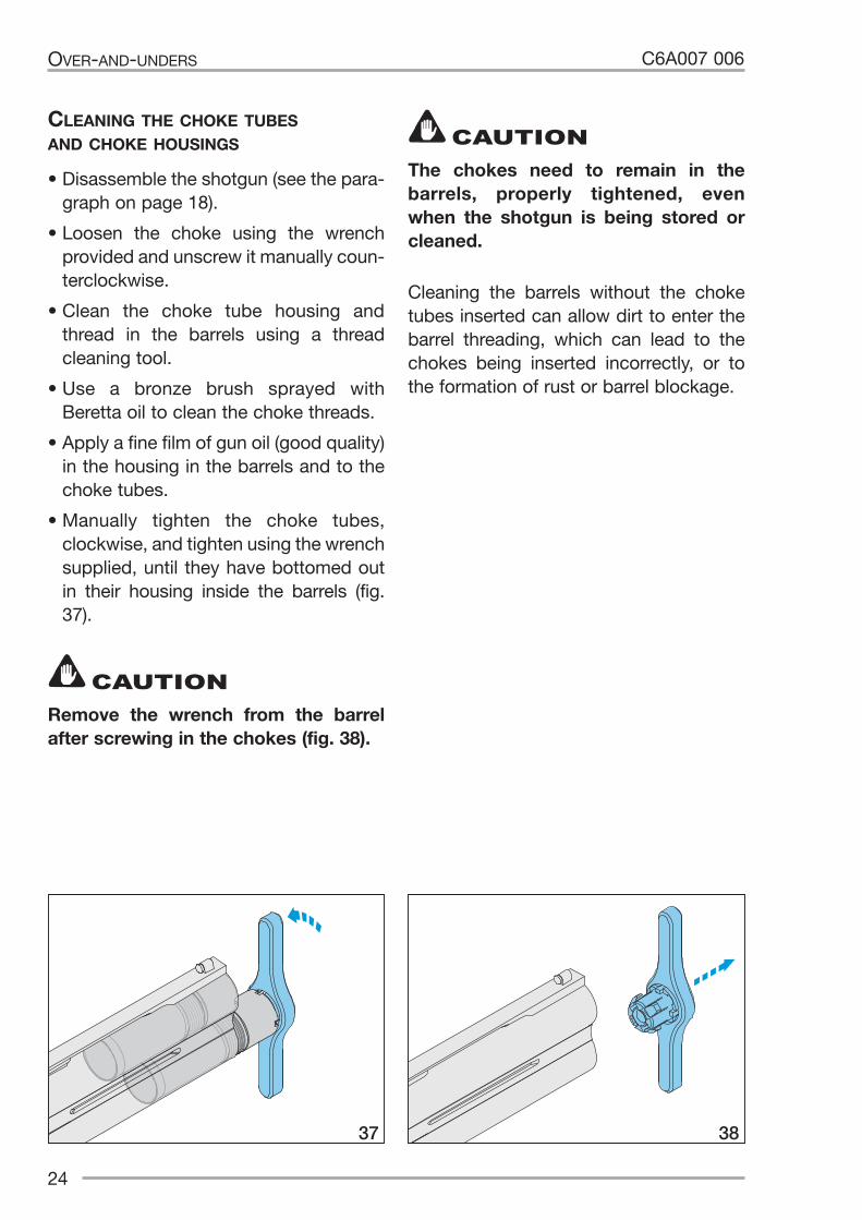
CLEANING THE CHOKE TUBES AND CHOKE HOUSINGS
• Disassemble the shotgun (see the para-graph on page 18).
• Loosen the choke using the wrench provided and unscrew it manually coun-terclockwise.
• Clean the choke tube housing and thread in the barrels using a thread cleaning tool.
• Use a bronze brush sprayed with Beretta oil to clean the choke threads.
• Apply a fine film of gun oil (good quality) in the housing in the barrels and to the choke tubes.
• Manually tighten the choke tubes, clock wise, and tighten using the wrench supplied, until they have bottomed out in their housing inside the barrels (fig. 37).
Cleaning the barrels without the choke tubes inserted can allow dirt to enter the barrel threading, which can lead to the chokes being inserted incorrectly, or to the formation of rust or barrel blockage.
24
OVER-AND-UNDERS C6A007 006
37 38
Remove the wrench from the barrel after screwing in the chokes (fig. 38).
CAUTION
The chokes need to remain in the barrels, properly tightened, even when the shotgun is being stored or cleaned.
CAUTION

C6A007 006
25
OVER-AND-UNDERS
Fixed and Beretta Chokes
Extra-long Beretta marking US name Rim notches choke tube (band colour)
0 (*) F (full) I White
00 (**) IM II Black (Improved Modified)
000 (***) M (Modified) III Green
0000 (****) IC IIII Yellow (Improved Cylinder)
C0000 (C****) CL (Cylinder) IIIII Blue
S SK USA without Purple
SK (Skeet Beretta) (1) SK (Skeet) without Red
without XF (Extra Full) without Brown
without LF (Light Full) without Grey
without LM (Light Modified) without Orange
(1) Beretta special skeet choke with negative value.
CHOKE IDENTIFICATION - FIG. 39 + TABLE
***
***
39

C6A007 006
26
OVER-AND-UNDERS
A
A
B
C
40
BUTT PLATE REPLACEMENT (PULL LENGTH ADJUSTMENT) - FIG. 40
A fastening screwsB butt plateC crosshead screwdriver
Procedure:
• loosen the fastening screws “A” and detach the butt plate “B”;
• fit the new butt plate and tighten the two fastening screws.
TRIGGER ADJUSTMENT - FIG. 41
• Loosen the trigger screw with the screwdriver provided, until the trigger can move freely; take care not to loosen the trigger completely so as to prevent the trigger bearing from coming out.
• Move the trigger forward or back, posi-tioning it in one of the grooves.
• Refit and tighten the side screw.
B-FAST STOCK ADJUSTMENT - FIG. 42
A comb fastening screwsB adjustable combC column fastening screwsD height and drop adjustment ringsE adjustment columnsF graded scaleG column base graded scaleL wrench provided
To prevent damage to the butt plate, we recommend applying petroleum jelly or grease to the screws “A” and the tip of the screwdriver “C”.
CAUTION
41

C6A007 006
Drop adjustment (use wrench “L”):
• loosen the screws “A” by about 2 turns, making sure they do not come out of their holes;
• lift and remove the comb “B”;
• to vary the drop, remove/add the rings “D” provided (ring thickness = 1 mm) (every slot on the column = 1 mm) up to a maximum of 10 rings “D” per column (fitting any more rings could damage the column and does not guarantee tightness). Rings are provided in the colors black and white: if they are fitted so that they alternate, it is easy to iden-tify and make a quick calculation of the height.
It is necessary to have at least one ring “D” on each column.
Once the adjustment has finished, refit the comb “B”, placing it on the columns “E”.
• tighten the lateral screws “A”.
27
OVER-AND-UNDERS
We recommend making these ad-justments on a table and keeping the stock in a horizontal position to prevent any parts from falling to the ground.
CAUTION
When removing and refitting the ad-justment columns “E”, turn the flat side towards the fastening screws “A”.
CAUTION
Comb cast adjustment (use wrench “L”):
• loosen the screws “A” by about 2 turns, making sure they do not come out of their holes;
• lift and remove the comb “B”;
• loosen the screws “C” by about half a turn;
• move the columns “E” to the left or right, until the adjustment is as required (refer to the graded scale: 1 notch = 1 mm max. lateral travel of each column = 7 mm right and 7 mm left, measured from the centre);
• tighten the screws “C”;
• refit the adjustable comb “B”, placing it in the correct position on the columns “E”;
• firmly tighten the lateral fastening screws “A”.
CEF
A
D
G
A
H
B
42
L

��
�
�
�
B-FAST RIB ADJUSTMENT- FIG. 43Some shotguns are fitted with a B-Fast adjustable rib to change the point of im-pact on the target and vary the rib height.
The B-Fast rib is equipped with:
“a” locking mechanism of adjustment wheel
“b” front adjustment mechanism“c” rear adjustment mechanism (avail-
able on certain models only) • adjustment wheel “D” • adjustment wheel lock “E” • screw “F” to fasten the adjustment
wheel • rib adjusting lock “G” • rib fastening screw “H” • wrench provided “L” • screwdriver provided “M”
To lock the adjustment wheel (a-fig. 44)
• Loosen the screw “F” and push it in-wards so that the lock “E” is allow ed to rotate.
• Rotate 90° the lock “E” and insert it into the horizontal seat.
• Tighten the screw “F”.
Front mechanism (b - fig. 45)
The front mechanism “b” serves to adjust the point of impact on the target with precision.
It has two graded scales:
• scale “1”, on the right side of the rib support, needs to be used when the rear mechanism “c” is in position 1;
• scale “2” (available on certain models only), on the left side of the rib support, needs to be used when the rear mech-anism “c” is in position 2.
The front mechanism has an adjustment wheel “D” for precision adjustment of the impact point on a target, raising or lower-ing the front part of the rib.
28
OVER-AND-UNDERS C6A007 006
45
43
44

Anything outside these limits may cause an annoying resonance effect when firing.
Rear mechanism (c - fig. 46) (available on certain models only)
The rear mechanism “c” serves to adjust rib height in one of two available pos-itions:
• position “1” (marked on the right side of the rib support) is a rib height of 25 mm
• position “2” (marked on the left side of the rib support) is a rib height of 30 mm
Rib height adjustment (models with rear adjustment only)
The shotgun is factory set with the rib in position 1, which is 25 mm.
To increase the height to 30 mm, proceed as described below:
• Use the wrench provided “L” to loosen the rib’s rear fastening screw “H”.
• Turn the adjustment wheel “D” as far as the topmost notch, taking care not to turn it too far.
• Loosen and remove the screw “H” (fig. 47).
• Raise the rib to position 2 (marked on the left side of the rib support).
• Insert the rib fastening screw “H” into its housing without tightening it.
• Remove the adjusting block “G” (use the wrench “L” to make the operation easier) (fig. 48).
29
OVER-AND-UNDERSC6A007 006
Do not turn the adjustment wheel “D” without first loosening the fastening screw “F”.
CAUTION
The rib adjusting block “G” must al-ways stay within the top or bottom limits of the graded scale.
CAUTION
�
� �
46
E47
C
F
48H
L
G

• Invert the position of the adjusting block “G”, inserting it into the housing on the left side (fig. 49).
• Tighten the rib fastening screw “H” all the way (fig. 50).
In order to change the point of im-pact on the target, proceed as de-scribed below:• Use the wrench provided “L” to loosen
the rib’s fastening screw “H”, turning it counterclockwise by about 1 turn.
• Turn the adjustment wheel “D” clock-wise or counterclockwise to reach the required point of impact.
• Turn the wheel clockwise to raise the point of impact and vice versa, counter-clockwise to lower it.
• After making the adjustment, tighten the fastening screw “H” by turning it clockwise.
B-FAST BALANCE ADJUSTMENT - FIG. 51
A butt plate fastening screwsB butt plateC adjustment ring/weightD ring/weight fasteningE fixed base
The exclusive balance adjustment system for the shotgun uses a set of metal rings/ weights “C” inside the stock.
To remove or add rings/weights inside the stock, proceed as follows:
• Use a crosshead screwdriver to remove the butt plate “B” (see the “Butt plate replacement” paragraph, page 26): the metal weights/rings are already inside, as installed in the factory.
• Unscrew and remove the ring/weight fastening screws “D”.
• Adjust the shotgun’s balance as need-ed by adding or removing metal rings/ weights.
30
OVER-AND-UNDERS C6A007 006
A
A
BC ED
51
C
49
E
50
G
H

C6A007 006
31
OVER-AND-UNDERS
The weight (in grams and ounces) of each ring/weight is shown on its side (fig. 52).
CAUTION
• It is not necessary to remove the fixed base “E”, fitted in the factory and se-cured to the stock.
• Refit the fastening screws “D”, passing it through the rings/weights and tight-en ing it with the crosshead screwdriver.
• Refit the butt plate “B” on the stock re-tainer (see the “Butt plate replacement” paragraph, page 26).
Barrel weight adjustment (if available)
It is possible to adjust the barrel weight by adding modular weights. The weights, complete with fastening mag nets, can be placed in the area under the fore-end.
Weights are available in the 5 g and 10 g sizes (fig. 53).
After removing the fore-end, the chosen weights need to be applied symmetrically in pairs on the left and right sides of the barrel.
There are five possible positions (fig. 54).
52
5354

EJECTION MODE SELECTION (690 SERIES)
There are two ways of spent cartridge selection to choose from: “automatic” or “manual extraction”. Manual extraction means it is easier to recover spent car-tridges, preventing them from fouling the environment.
After removing the fore-end, (see the “Disassembly” paragraph, page 18) and without removing the barrels from the receiver, grip the barrel and find the two selectors (fig. 55).
Use a screwdriver of a suitable size to turn each selector a 1/4 turn until it stops:
• teeth facing outward = automatic ejection (fig. 56);
• teeth facing inward = manual ejec-tion (fig. 57).
32
OVER-AND-UNDERS C6A007 006
55
5756
Make sure that the selectors are al-ways at their limit: if partially moved in the midway position, it will not be possible to refit the fore-end.
CAUTION

INTERCHANGEABLE TRIGGER GROUPS (SERIES DT)
TRIGGER GROUP DISASSEMBLY
• Disassemble the barrels (see “Dis-assembly”, page 18), and close the opening lever.
• Push the safety forward, past the shoot-ing position: the safety will click into place and a white dot will be visible (fig. 58).
• Turn the top lever to the right and par-tially open the barrels (fig. 59).
• Grip the group and slide it off the receiv er, pulling it downward without forcing it (fig. 60).
If the group does not slide off easily, close the shotgun and repeat the first steps.
33
OVER-AND-UNDERSC6A007 006
The trigger group should only be re-moved if it is being replaced or un-dergoing extraordinary maintenance and/or repairs.
CAUTION
The trigger group is no longer locked and can slide off the shotgun.
CAUTION
58
5960

REFITTING THE TRIGGER GROUP
To make it easier to fit the trigger group, it is best to cock the hammers by moving them back firmly with your thumb (fig. 61).
• Slide the front trigger tang into the re-ceiver (fig. 62).
• Turn the group upwards and place it in its housing.
• Refit the barrels (see “Assembly” on page 10).
• Close the barrels.
FIRING PIN REPLACEMENT (DT SERIES) - FIG. 63
A bottom firing pin retaining pinB firing pinC firing pin springD top firing pin retaining pin
34
OVER-AND-UNDERS C6A007 006
61
62
AB C
D
63

Bottom firing pin procedure (fig. 64):
• to facilitate the operation, remove the trigger (see the paragraph on page 33);
• remove the stock (see the paragraph “Stock removal” on page 19);
• take out the retaining pin “A” of the fir-ing pin;
• side out the firing pin “B” with the rele-vant spring “C”;
• insert the new spring and firing pin (fac-ing them the correct way) (see fig. 65);
• insert the pin “A”.
Follow the same procedure for the top retaining pin.
35
OVER-AND-UNDERSC6A007 006
AB C
64
B
A
C
65

36
OVER-AND-UNDERS C6A007 006
SLING SWIVEL ASSEMBLY (SERIES SV 609 ULTRALIGHT ONLY)
CAUTIONWe recommend carrying out this as-sembly over a table to avoid any pos-sible dropping of parts.
• Loosen and remove the screw/pin of the sling swivel (fig. 66);
• detach the swivel (fig. 67);
• loosen and take out the sling swivel bushing (fig. 68);
• loosen and take out the two screws from the swivel support (fig. 69);
• separate the three parts of the swivel and position them correctly on the bar-rels, following the layout shown in figure 70 (A+B on the right side of the barrel – C on the left);67
66
68
69 70

37
C6A007 006 OVER-AND-UNDERS
75
• screw in the two sling swivel screws without tightening them all the way; make sure that the distance from the edge of the fore-end is L = 5 cm (fig. 71);
• fit the bushing and tighten it fully (fig. 72);
• fit the swivel on the support and secure it with the screw/pin (figs. 73 – 74).
Once assembly is complete, tighten the two screws on the support to the torque stated in figure 75.
72
71
73
74

38
OVER-AND-UNDERS C6A007 006
STORAGE WARRANTY
STORE YOUR SHOTGUN SO THAT CHILDREN CANNOT GAIN ACCESS TO IT. TO REDUCE THE RISK OF ACCIDENTS INVOLVING CHILDREN, UNLOAD YOUR FIREARM, LOCK IT AWAY AND STORE THE AMMUNITION IN A SEPARATE LOCKED LOCATION.
WARNING
Store the shotgun disassembled (barrels/fore-end and receiver/stock) in the supplied case. Before storage, always check the conditions of the shotgun and its case. Make sure that they are perfectly dry. Moisture and water drops could cause damage to the shotgun.
CAUTION
The Warranty and extension of the warranty period is packed with your shotgun Beretta. Please refer to the WARRANTY and the related instructions should a repair service be required under the warranty period.
CAUTION
Wholesalers, dealers or gunsmiths (un-less they are a Repair Station authorized by the Manufacturer) are not authorized to make any Warranty repair or adjust-ment on behalf of the Manufacturer.
Notice
The Warranty is effective only for the original retail purchaser of the shotgun.
Notice

C6A007 006 OVER-AND-UNDERS

FABBRICA D’ARMI P. BERETTA S.P.A.VIA PIETRO BERETTA, 18I 25063 GARDONE VAL TROMPIA, BRESCIA, ITALY
BERETTA.COM
SHO
TGU
NU
SER
MA
NU
AL
OV
ER &
UN
DER