Embed Size (px)
Citation preview
(800) 238-7514 www.ptsupply.comWe work where you work. 1
Outside Telephone
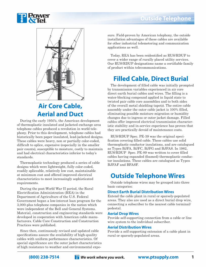
Air Core Cable, Aerial and Duct
During the early 1950’s, the American development of thermoplastic insulated and jacketed exchange area telephone cables produced a revolution in world tele-phony. Prior to this development, telephone cables had historically been paper insulated, lead-jacketed designs. These cables were heavy, non or partially color-coded, difficult to splice, expensive (especially in the smaller pair counts), susceptible to moisture, costly to maintain and had electrical characteristics inferior to today’s standards.
Thermoplastic technology produced a series of cable designs which were lightweight, fully color-coded, readily spliceable, relatively low cost, maintainable at minimum cost and offered improved electrical characteristics to meet increasingly sophisticated requirements.
During the post-World War II period, the Rural Electrification Administration (REA) in the Department of Agriculture of the U.S. Federal Government began a low-interest loan program for the 3,000-plus telephone companies in the nation which were independent of the Bell and General Systems. Material, construction and engineering standards were developed in cooperation with American cable manu-facturers. Cable Core Construction and Construction Practices were published.
Since then, continuously revised and updated cable specifications assure the availability of high-quality cables with uniform performance characteristics. Of special significance are the outer jacket characteristics of high resistance to weather and environmental expo-
sure. Field-proven by American telephony, the outside installation advantages of these cables are available for other industrial telemetering and communication applications as well.
Today, REA has been reidentified as RUS/RDUP to cover a wider range of rurally placed utility services. Our RUS/RDUP designations name a certifiable family of product within telecommunications.
Filled Cable, Direct BurialThe development of filled cable was initially prompted
by transmission variables experienced in air core direct earth burial cables and wires. The filling is a water-blocking compound applied in liquid state to twisted pair cable core assemblies and to both sides of the overall metal shielding tape(s). The entire cable assembly under the outer cable jacket is 100% filled, eliminating possible moisture migration or humidity changes due to ingress or outer jacket damage. Filled cables offer improved electrical transmission character-istic stability and in-service experience has proven that they are practically devoid of maintenance costs.
RUS/RDUP Spec. PE-39 was the original speci-fication covering filled cable. These cables use solid thermoplastic conductor insulations, and are catalogued as Types BJFA, BJFC, BJFG and BJFAS. In 1982, RUS/RDUP Spec. PE-89 was written to cover filled cables having expanded (foamed) thermoplastic conduc-tor insulations. These cables are catalogued as Types BJFAF and BFASF.
Outside Telephone WiresOutside telephone wires may be grouped into three
basic categories:Direct Earth Burial Distribution WiresExtend the cable plant in rural or sparsely-populated areas. They also are used as a direct burial drop wire, connecting a subscriber to the nearest cable terminal/pedestal.Aerial Drop WiresProvide self-supporting connection from a cable or line wire system to the individual subscriber.Aerial Distribution WiresProvide a self-supporting extension of a cable plant in rural or sparsely-populated areas.
(800) 238-7514 www.ptsupply.comWe work where you work.2
Air Core Cable
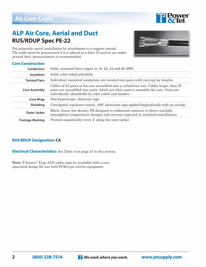
ALP Air Core, Aerial and Duct RUS/RDUP Spec PE-22For primarily aerial installation by attachment to a support strand.The cable must be pressurized if it is placed in a duct. If used in an under-ground duct, pressurization is recommended.
RUS/RDUP Designation: CA
Electrical Characteristics: See Table A on page 21 in this section.
Note: T-Screen® Type ALP cables may be available with a core separated design for use with PCM-type carrier equipment.
Conductors Solid, annealed bare copper in 19, 22, 24 and 26 AWGInsulation Solid, color-coded polyolefin
Twisted Pairs Individual insulated conductors are twisted into pairs with varying lay lengths
Core AssemblyCables of 25 pairs or less are assembled into a cylindrical core. Cables larger than 25 pairs are assembled into units, which are then used to assemble the core. Units are individually identifiable by color coded unit binders.
Core Wrap Non-hygroscopic, dielectric tapeShielding Corrugated, copolymer coated, .008" aluminum tape applied longitudinally with an overlap
Outer Jacket Black, linear low-density PE designed to withstand exposure to direct sunlight, atmospheric temperature changes and stresses expected in standard installations
Footage Marking Printed sequentially every 2' along the outer jacket
Core Construction
(800) 238-7514 www.ptsupply.comWe work where you work. 3
Air Core Cable
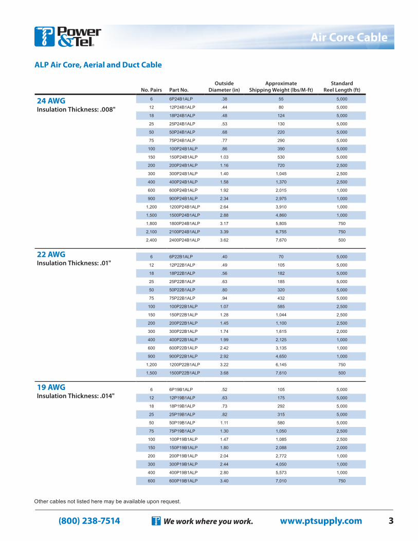
ALP Air Core, Aerial and Duct Cable
Other cables not listed here may be available upon request.
No. Pairs Part No.Outside
Diameter (in)Approximate
Shipping Weight (lbs/M-ft)Standard
Reel Length (ft)
24 AWG Insulation Thickness: .008"
6 6P24B1ALP .38 55 5,000
12 12P24B1ALP .44 80 5,000
18 18P24B1ALP .48 124 5,000
25 25P24B1ALP .53 130 5,000
50 50P24B1ALP .68 220 5,000
75 75P24B1ALP .77 290 5,000
100 100P24B1ALP .86 390 5,000
150 150P24B1ALP 1.03 530 5,000
200 200P24B1ALP 1.16 720 2,500
300 300P24B1ALP 1.40 1,045 2,500
400 400P24B1ALP 1.58 1,370 2,500
600 600P24B1ALP 1.92 2,015 1,000
900 900P24B1ALP 2.34 2,975 1,000
1,200 1200P24B1ALP 2.64 3,910 1,000
1,500 1500P24B1ALP 2.88 4,860 1,000
1,800 1800P24B1ALP 3.17 5,805 750
2,100 2100P24B1ALP 3.39 6,755 750
2,400 2400P24B1ALP 3.62 7,670 500
22 AWG Insulation Thickness: .01"
6 6P22B1ALP .40 70 5,000
12 12P22B1ALP .49 105 5,000
18 18P22B1ALP .56 182 5,000
25 25P22B1ALP .63 185 5,000
50 50P22B1ALP .80 320 5,000
75 75P22B1ALP .94 432 5,000
100 100P22B1ALP 1.07 585 2,500
150 150P22B1ALP 1.28 1,044 2,500
200 200P22B1ALP 1.45 1,100 2,500
300 300P22B1ALP 1.74 1,615 2,000
400 400P22B1ALP 1.99 2,125 1,000
600 600P22B1ALP 2.42 3,135 1,000
900 900P22B1ALP 2.92 4,650 1,000
1,200 1200P22B1ALP 3.22 6,145 750
1,500 1500P22B1ALP 3.68 7,610 500
19 AWG Insulation Thickness: .014"
6 6P19B1ALP .52 105 5,000
12 12P19B1ALP .63 175 5,000
18 18P19B1ALP .73 292 5,000
25 25P19B1ALP .82 315 5,000
50 50P19B1ALP 1.11 580 5,000
75 75P19B1ALP 1.30 1,050 2,500
100 100P19B1ALP 1.47 1,085 2,500
150 150P19B1ALP 1.80 2,088 2,000
200 200P19B1ALP 2.04 2,772 1,000
300 300P19B1ALP 2.44 4,050 1,000
400 400P19B1ALP 2.80 5,573 1,000
600 600P19B1ALP 3.40 7,010 750
(800) 238-7514 www.ptsupply.comWe work where you work.4
Air Core Cable
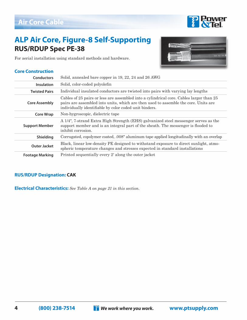
ALP Air Core, Figure-8 Self-Supporting RUS/RDUP Spec PE-38For aerial installation using standard methods and hardware.
RUS/RDUP Designation: CAK
Electrical Characteristics: See Table A on page 21 in this section.
Conductors Solid, annealed bare copper in 19, 22, 24 and 26 AWGInsulation Solid, color-coded polyolefin
Twisted Pairs Individual insulated conductors are twisted into pairs with varying lay lengths
Core AssemblyCables of 25 pairs or less are assembled into a cylindrical core. Cables larger than 25 pairs are assembled into units, which are then used to assemble the core. Units are individually identifiable by color coded unit binders.
Core Wrap Non-hygroscopic, dielectric tape
Support MemberA 1/4", 7-strand Extra High Strength (EHS) galvanized steel messenger serves as the support member and is an integral part of the sheath. The messenger is flooded to inhibit corrosion.
Shielding Corrugated, copolymer coated, .008" aluminum tape applied longitudinally with an overlap
Outer Jacket Black, linear low-density PE designed to withstand exposure to direct sunlight, atmo-spheric temperature changes and stresses expected in standard installations
Footage Marking Printed sequentially every 2' along the outer jacket
Core Construction
(800) 238-7514 www.ptsupply.comWe work where you work. 5
Air Core Cable
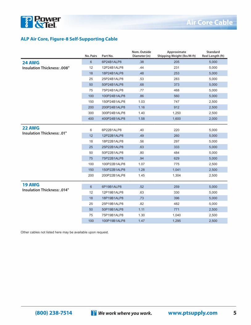
ALP Air Core, Figure-8 Self-Supporting Cable
Other cables not listed here may be available upon request.
No. Pairs Part No.Nom. Outside Diameter (in)
Approximate Shipping Weight (lbs/M-ft)
Standard Reel Length (ft)
24 AWGInsulation Thickness: .008"
6 6P24B1ALP8 .38 205 5,000
12 12P24B1ALP8 .44 231 5,000
18 18P24B1ALP8 .48 253 5,000
25 25P24B1ALP8 .53 283 5,000
50 50P24B1ALP8 .68 373 5,000
75 75P24B1ALP8 .77 468 5,000
100 100P24B1ALP8 .86 560 5,000
150 150P24B1ALP8 1.03 747 2,500
200 200P24B1ALP8 1.16 912 2,500
300 300P24B1ALP8 1.40 1,250 2,500
400 400P24B1ALP8 1.58 1,600 2,000
22 AWG Insulation Thickness: .01"
6 6P22B1ALP8 .40 220 5,000
12 12P22B1ALP8 .49 260 5,000
18 18P22B1ALP8 .56 297 5,000
25 25P22B1ALP8 .63 333 5,000
50 50P22B1ALP8 .80 484 5,000
75 75P22B1ALP8 .94 629 5,000
100 100P22B1ALP8 1.07 775 2,500
150 150P22B1ALP8 1.28 1,041 2,500
200 200P22B1ALP8 1.45 1,304 2,500
19 AWG Insulation Thickness: .014"
6 6P19B1ALP8 .52 259 5,000
12 12P19B1ALP8 .63 330 5,000
18 18P19B1ALP8 .73 396 5,000
25 25P19B1ALP8 .82 482 5,000
50 50P19B1ALP8 1.11 771 2,500
75 75P19B1ALP8 1.30 1,040 2,500
100 100P19B1ALP8 1.47 1,295 2,500

(800) 238-7514 www.ptsupply.comWe work where you work.6
Filled Cable
Filled, Direct Burial, Aerial, Duct, BJFA RUS/RDUP Spec PE-39 For direct burial or duct applications where protection from moisture is required and aluminum shielding desired. May also be used aerially if attached to a support strand.
RUS/RDUP Designation: BFCA
Electrical Characteristics: See Table B on page 21 in this section.
Note: T-Screen® Type BJFA cables may be available with a core separated design for use with PCM-type carrier equipment.
Conductors Solid annealed copper in 19, 22, 24 and 26 AWGInsulation Solid, color-coded polyolefin
Twisted Pairs Individual insulated conductors are twisted into pairs with varying lay lengths
Core AssemblyCables of 25 pairs or less are assembled into a cylindrical core. Cables larger than 25 pairs are assembled into units, which are then used to assemble the core. Units are individually identifiable by color coded unit binders.
Filling Compound The core assembly is filled with an 80°C ETPR compound, completely filling the inter-stices between the pairs and under the core wrap
Core Wrap Non-hygroscopic, dielectric tape
Shielding A corrugated, copolymer coated, .008" aluminum tape is applied longitudinally with an overlap. The shield interfaces are flooded.
Outer Jacket Black, linear low-density PE designed to withstand exposure to direct sunlight, atmo-spheric temperature changes and stresses expected in standard installations
Footage Marking Printed sequentially every 2' along the outer jacket
Core Construction
(800) 238-7514 www.ptsupply.comWe work where you work. 7
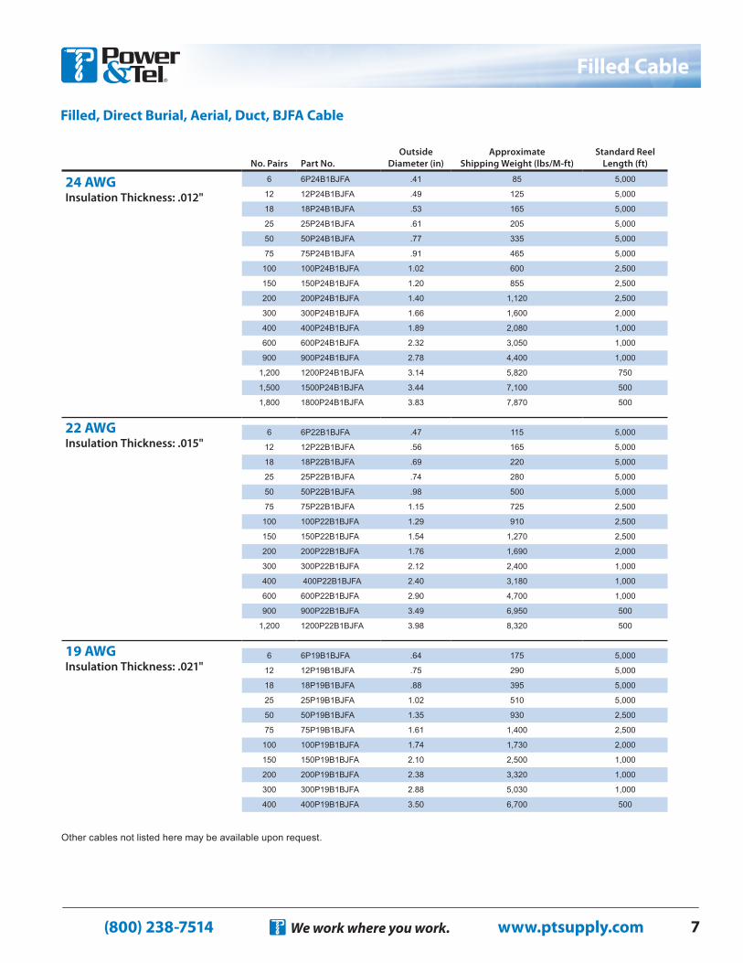
Filled Cable
Filled, Direct Burial, Aerial, Duct, BJFA Cable
No. Pairs Part No.Outside
Diameter (in)Approximate
Shipping Weight (lbs/M-ft)Standard Reel
Length (ft)
24 AWG Insulation Thickness: .012"
6 6P24B1BJFA .41 85 5,000
12 12P24B1BJFA .49 125 5,000
18 18P24B1BJFA .53 165 5,000
25 25P24B1BJFA .61 205 5,000
50 50P24B1BJFA .77 335 5,000
75 75P24B1BJFA .91 465 5,000
100 100P24B1BJFA 1.02 600 2,500
150 150P24B1BJFA 1.20 855 2,500
200 200P24B1BJFA 1.40 1,120 2,500
300 300P24B1BJFA 1.66 1,600 2,000
400 400P24B1BJFA 1.89 2,080 1,000
600 600P24B1BJFA 2.32 3,050 1,000
900 900P24B1BJFA 2.78 4,400 1,000
1,200 1200P24B1BJFA 3.14 5,820 750
1,500 1500P24B1BJFA 3.44 7,100 500
1,800 1800P24B1BJFA 3.83 7,870 500
22 AWG Insulation Thickness: .015"
6 6P22B1BJFA .47 115 5,000
12 12P22B1BJFA .56 165 5,000
18 18P22B1BJFA .69 220 5,000
25 25P22B1BJFA .74 280 5,000
50 50P22B1BJFA .98 500 5,000
75 75P22B1BJFA 1.15 725 2,500
100 100P22B1BJFA 1.29 910 2,500
150 150P22B1BJFA 1.54 1,270 2,500
200 200P22B1BJFA 1.76 1,690 2,000
300 300P22B1BJFA 2.12 2,400 1,000
400 400P22B1BJFA 2.40 3,180 1,000
600 600P22B1BJFA 2.90 4,700 1,000
900 900P22B1BJFA 3.49 6,950 500
1,200 1200P22B1BJFA 3.98 8,320 500
19 AWG Insulation Thickness: .021"
6 6P19B1BJFA .64 175 5,000
12 12P19B1BJFA .75 290 5,000
18 18P19B1BJFA .88 395 5,000
25 25P19B1BJFA 1.02 510 5,000
50 50P19B1BJFA 1.35 930 2,500
75 75P19B1BJFA 1.61 1,400 2,500
100 100P19B1BJFA 1.74 1,730 2,000
150 150P19B1BJFA 2.10 2,500 1,000
200 200P19B1BJFA 2.38 3,320 1,000
300 300P19B1BJFA 2.88 5,030 1,000
400 400P19B1BJFA 3.50 6,700 500
Other cables not listed here may be available upon request.
(800) 238-7514 www.ptsupply.comWe work where you work.8
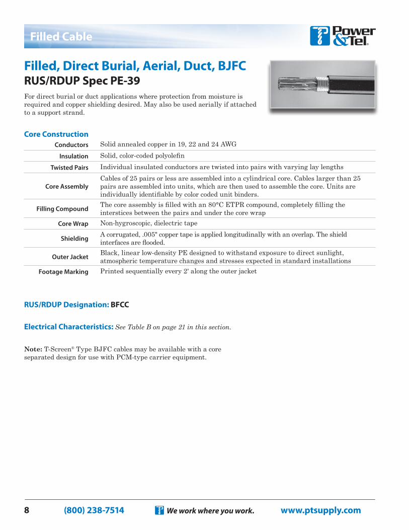
Filled Cable
Filled, Direct Burial, Aerial, Duct, BJFC RUS/RDUP Spec PE-39For direct burial or duct applications where protection from moisture is required and copper shielding desired. May also be used aerially if attached to a support strand.
RUS/RDUP Designation: BFCC
Electrical Characteristics: See Table B on page 21 in this section.
Note: T-Screen® Type BJFC cables may be available with a core separated design for use with PCM-type carrier equipment.
Conductors Solid annealed copper in 19, 22 and 24 AWGInsulation Solid, color-coded polyolefin
Twisted Pairs Individual insulated conductors are twisted into pairs with varying lay lengths
Core AssemblyCables of 25 pairs or less are assembled into a cylindrical core. Cables larger than 25 pairs are assembled into units, which are then used to assemble the core. Units are individually identifiable by color coded unit binders.
Filling Compound The core assembly is filled with an 80°C ETPR compound, completely filling the interstices between the pairs and under the core wrap
Core Wrap Non-hygroscopic, dielectric tape
Shielding A corrugated, .005" copper tape is applied longitudinally with an overlap. The shield interfaces are flooded.
Outer Jacket Black, linear low-density PE designed to withstand exposure to direct sunlight, atmospheric temperature changes and stresses expected in standard installations
Footage Marking Printed sequentially every 2' along the outer jacket
Core Construction
(800) 238-7514 www.ptsupply.comWe work where you work. 9
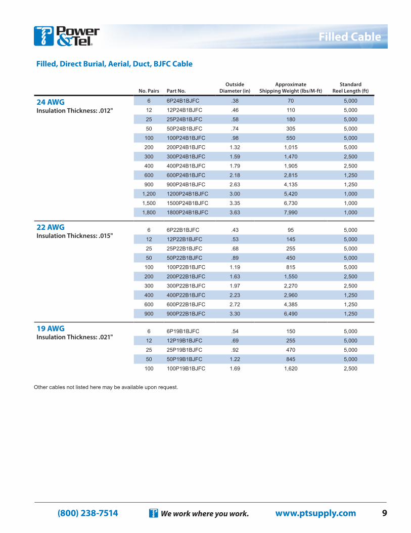
Filled Cable
No. Pairs Part No.Outside
Diameter (in)Approximate
Shipping Weight (lbs/M-ft)Standard
Reel Length (ft)
24 AWG Insulation Thickness: .012"
6 6P24B1BJFC .38 70 5,000
12 12P24B1BJFC .46 110 5,000
25 25P24B1BJFC .58 180 5,000
50 50P24B1BJFC .74 305 5,000
100 100P24B1BJFC .98 550 5,000
200 200P24B1BJFC 1.32 1,015 5,000
300 300P24B1BJFC 1.59 1,470 2,500
400 400P24B1BJFC 1.79 1,905 2,500
600 600P24B1BJFC 2.18 2,815 1,250
900 900P24B1BJFC 2.63 4,135 1,250
1,200 1200P24B1BJFC 3.00 5,420 1,000
1,500 1500P24B1BJFC 3.35 6,730 1,000
1,800 1800P24B1BJFC 3.63 7,990 1,000
22 AWG Insulation Thickness: .015"
6 6P22B1BJFC .43 95 5,000
12 12P22B1BJFC .53 145 5,000
25 25P22B1BJFC .68 255 5,000
50 50P22B1BJFC .89 450 5,000
100 100P22B1BJFC 1.19 815 5,000
200 200P22B1BJFC 1.63 1,550 2,500
300 300P22B1BJFC 1.97 2,270 2,500
400 400P22B1BJFC 2.23 2,960 1,250
600 600P22B1BJFC 2.72 4,385 1,250
900 900P22B1BJFC 3.30 6,490 1,250
19 AWG Insulation Thickness: .021"
6 6P19B1BJFC .54 150 5,000
12 12P19B1BJFC .69 255 5,000
25 25P19B1BJFC .92 470 5,000
50 50P19B1BJFC 1.22 845 5,000
100 100P19B1BJFC 1.69 1,620 2,500
Other cables not listed here may be available upon request.
Filled, Direct Burial, Aerial, Duct, BJFC Cable
(800) 238-7514 www.ptsupply.comWe work where you work.10
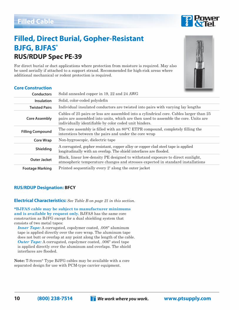
Filled Cable
Filled, Direct Burial, Gopher-Resistant BJFG, BJFAS*
RUS/RDUP Spec PE-39For direct burial or duct applications where protection from moisture is required. May also be used aerially if attached to a support strand. Recommended for high-risk areas where additional mechanical or rodent protection is required.
RUS/RDUP Designation: BFCY
Electrical Characteristics: See Table B on page 21 in this section.
*BJFAS cable may be subject to manufacturer minimums and is available by request only. BJFAS has the same core construction as BJFG except for a dual shielding system that consists of two metal tapes:
Inner Tape: A corrugated, copolymer coated, .008" aluminum tape is applied directly over the core wrap. The aluminum tape does not butt or overlap at any point along the length of the cable.Outer Tape: A corrugated, copolymer coated, .006" steel tape is applied directly over the aluminum and overlaps. The shield interfaces are flooded.
Note: T-Screen® Type BJFG cables may be available with a core separated design for use with PCM-type carrier equipment.
Conductors Solid annealed copper in 19, 22 and 24 AWGInsulation Solid, color-coded polyolefin
Twisted Pairs Individual insulated conductors are twisted into pairs with varying lay lengths
Core AssemblyCables of 25 pairs or less are assembled into a cylindrical core. Cables larger than 25 pairs are assembled into units, which are then used to assemble the core. Units are individually identifiable by color coded unit binders.
Filling Compound The core assembly is filled with an 80°C ETPR compound, completely filling the interstices between the pairs and under the core wrap
Core Wrap Non-hygroscopic, dielectric tape
Shielding A corrugated, gopher resistant, copper alloy or copper clad steel tape is applied longitudinally with an overlap. The shield interfaces are flooded.
Outer Jacket Black, linear low-density PE designed to withstand exposure to direct sunlight, atmospheric temperature changes and stresses expected in standard installations
Footage Marking Printed sequentially every 2' along the outer jacket
Core Construction

(800) 238-7514 www.ptsupply.comWe work where you work. 11
Filled Cable
Filled, Direct Burial, Gopher-Resistant, BJFG Cable
Other cables not listed here may be available upon request.
No. Pairs Part No.Outside
Diameter (in)Approximate
Shipping Weight (lbs/M-ft)Standard
Reel Length (ft)
24 AWG Insulation Thickness: .012"
6 6P24B1BJFG .41 100 5,000
12 12P24B1BJFG .49 140 5,000
18 18P24B1BJFG .53 180 5,000
25 25P24B1BJFG .61 225 5,000
50 50P24B1BJFG .77 365 5,000
75 75P24B1BJFG .91 495 5,000
100 100P24B1BJFG 1.02 630 2,500
150 150P24B1BJFG 1.20 900 2,500
200 200P24B1BJFG 1.40 1,160 2,500
300 300P24B1BJFG 1.66 1,670 2,000
400 400P24B1BJFG 1.89 2,160 1,000
600 600P24B1BJFG 2.32 3,140 1,000
900 900P24B1BJFG 2.78 4,520 1,000
1,200 1200P24B1BJFG 3.14 5,940 750
1,500 1500P24B1BJFG 3.44 7,280 500
1,800 1800P24B1BJFG 3.83 8,005 500
22 AWG Insulation Thickness: .015"
6 6P22B1BJFG .47 130 5,000
12 12P22B1BJFG .56 185 5,000
18 18P22B1BJFG .69 240 5,000
25 25P22B1BJFG .74 305 5,000
50 50P22B1BJFG .98 530 5,000
75 75P22B1BJFG 1.15 765 2,500
100 100P22B1BJFG 1.29 955 2,500
150 150P22B1BJFG 1.54 1,320 2,500
200 200P22B1BJFG 1.76 1,770 2,000
300 300P22B1BJFG 2.12 2,480 1,000
400 400P22B1BJFG 2.40 3,260 1,000
600 600P22B1BJFG 2.90 4,810 1,000
900 900P22B1BJFG 3.49 7,120 500
1,200 1200P22B1BJFG 3.98 9,400 500
19 AWG Insulation Thickness: .021"
6 6P19B1BJFG .64 195 5,000
12 12P19B1BJFG .75 315 5,000
18 18P19B1BJFG .88 425 5,000
25 25P19B1BJFG 1.02 545 5,000
50 50P19B1BJFG 1.35 975 2,500
75 75P19B1BJFG 1.61 1,460 2,500
100 100P19B1BJFG 1.74 1,800 2,000
150 150P19B1BJFG 2.10 2,590 1,000
200 200P19B1BJFG 2.38 3,420 1,000
300 300P19B1BJFG 2.88 5,160 1,000
400 400P19B1BJFG 3.50 6,710 500
(800) 238-7514 www.ptsupply.comWe work where you work.12
Filled Cable
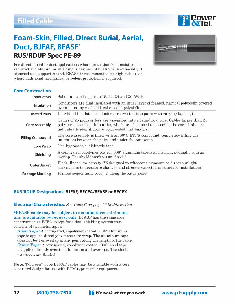
Foam-Skin, Filled, Direct Burial, Aerial, Duct, BJFAF, BFASF*
RUS/RDUP Spec PE-89For direct burial or duct applications where protection from moisture is required and aluminum shielding is desired. May also be used aerially if attached to a support strand. BFASF is recommended for high-risk areas where additional mechanical or rodent protection is required.
RUS/RDUP Designations: BJFAF, BFCEA/BFASF or BFCEX
Electrical Characteristics: See Table C on page 22 in this section.
*BFASF cable may be subject to manufacturer minimums and is available by request only. BFASF has the same core construction as BJFG except for a dual shielding system that consists of two metal tapes:
Inner Tape: A corrugated, copolymer coated, .008" aluminum tape is applied directly over the core wrap. The aluminum tape does not butt or overlap at any point along the length of the cable.Outer Tape: A corrugated, copolymer coated, .006" steel tape is applied directly over the aluminum and overlaps. The shield interfaces are flooded.
Note: T-Screen® Type BJFAF cables may be available with a core separated design for use with PCM-type carrier equipment.
Conductors Solid annealed copper in 19, 22, 24 and 26 AWG
Insulation Conductors are dual insulated with an inner layer of foamed, natural polyolefin covered by an outer layer of solid, color-coded polyolefin
Twisted Pairs Individual insulated conductors are twisted into pairs with varying lay lengths
Core AssemblyCables of 25 pairs or less are assembled into a cylindrical core. Cables larger than 25 pairs are assembled into units, which are then used to assemble the core. Units are individually identifiable by color coded unit binders.
Filling Compound The core assembly is filled with an 80°C ETPR compound, completely filling the interstices between the pairs and under the core wrap
Core Wrap Non-hygroscopic, dielectric tape
Shielding A corrugated, copolymer coated, .008" aluminum tape is applied longitudinally with an overlap. The shield interfaces are flooded.
Outer Jacket Black, linear low-density PE designed to withstand exposure to direct sunlight, atmospheric temperature changes and stresses expected in standard installations
Footage Marking Printed sequentially every 2' along the outer jacket
Core Construction
(800) 238-7514 www.ptsupply.comWe work where you work. 13
Filled Cable
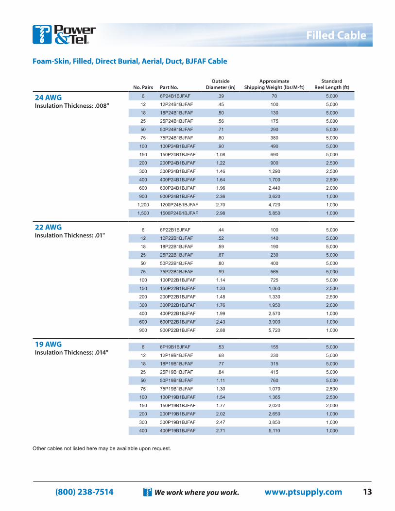
Foam-Skin, Filled, Direct Burial, Aerial, Duct, BJFAF Cable
Other cables not listed here may be available upon request.
No. Pairs Part No.Outside
Diameter (in)Approximate
Shipping Weight (lbs/M-ft)Standard
Reel Length (ft)
24 AWG Insulation Thickness: .008"
6 6P24B1BJFAF .39 70 5,000
12 12P24B1BJFAF .45 100 5,000
18 18P24B1BJFAF .50 130 5,000
25 25P24B1BJFAF .56 175 5,000
50 50P24B1BJFAF .71 290 5,000
75 75P24B1BJFAF .80 380 5,000
100 100P24B1BJFAF .90 490 5,000
150 150P24B1BJFAF 1.08 690 5,000
200 200P24B1BJFAF 1.22 900 2,500
300 300P24B1BJFAF 1.46 1,290 2,500
400 400P24B1BJFAF 1.64 1,700 2,500
600 600P24B1BJFAF 1.96 2,440 2,000
900 900P24B1BJFAF 2.36 3,620 1,000
1,200 1200P24B1BJFAF 2.70 4,720 1,000
1,500 1500P24B1BJFAF 2.98 5,850 1,000
22 AWG Insulation Thickness: .01"
6 6P22B1BJFAF .44 100 5,000
12 12P22B1BJFAF .52 140 5,000
18 18P22B1BJFAF .59 190 5,000
25 25P22B1BJFAF .67 230 5,000
50 50P22B1BJFAF .80 400 5,000
75 75P22B1BJFAF .99 565 5,000
100 100P22B1BJFAF 1.14 725 5,000
150 150P22B1BJFAF 1.33 1,060 2,500
200 200P22B1BJFAF 1.48 1,330 2,500
300 300P22B1BJFAF 1.76 1,950 2,000
400 400P22B1BJFAF 1.99 2,570 1,000
600 600P22B1BJFAF 2.43 3,900 1,000
900 900P22B1BJFAF 2.88 5,720 1,000
19 AWG Insulation Thickness: .014"
6 6P19B1BJFAF .53 155 5,000
12 12P19B1BJFAF .68 230 5,000
18 18P19B1BJFAF .77 315 5,000
25 25P19B1BJFAF .84 415 5,000
50 50P19B1BJFAF 1.11 760 5,000
75 75P19B1BJFAF 1.30 1,070 2,500
100 100P19B1BJFAF 1.54 1,365 2,500
150 150P19B1BJFAF 1.77 2,020 2,000
200 200P19B1BJFAF 2.02 2,650 1,000
300 300P19B1BJFAF 2.47 3,850 1,000
400 400P19B1BJFAF 2.71 5,110 1,000
(800) 238-7514 www.ptsupply.comWe work where you work.14
Filled Cable
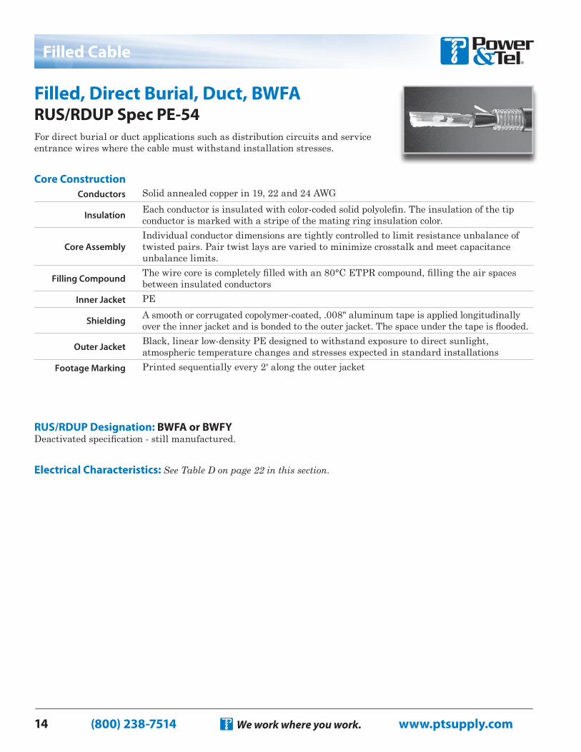
Filled, Direct Burial, Duct, BWFA RUS/RDUP Spec PE-54For direct burial or duct applications such as distribution circuits and service entrance wires where the cable must withstand installation stresses.
RUS/RDUP Designation: BWFA or BWFYDeactivated specification - still manufactured.
Electrical Characteristics: See Table D on page 22 in this section.
Conductors Solid annealed copper in 19, 22 and 24 AWG
Insulation Each conductor is insulated with color-coded solid polyolefin. The insulation of the tip conductor is marked with a stripe of the mating ring insulation color.
Core AssemblyIndividual conductor dimensions are tightly controlled to limit resistance unbalance of twisted pairs. Pair twist lays are varied to minimize crosstalk and meet capacitance unbalance limits.
Filling Compound The wire core is completely filled with an 80°C ETPR compound, filling the air spaces between insulated conductors
Inner Jacket PE
Shielding A smooth or corrugated copolymer-coated, .008" aluminum tape is applied longitudinally over the inner jacket and is bonded to the outer jacket. The space under the tape is flooded.
Outer Jacket Black, linear low-density PE designed to withstand exposure to direct sunlight, atmospheric temperature changes and stresses expected in standard installations
Footage Marking Printed sequentially every 2' along the outer jacket
Core Construction
(800) 238-7514 www.ptsupply.comWe work where you work. 15
Filled Cable
Other cables not listed here may be available upon request.
No. Pairs Part No.Nominal O.D. (in)
Approximate Shipping Weight (lbs/M-ft)
Standard Reel Length (ft)
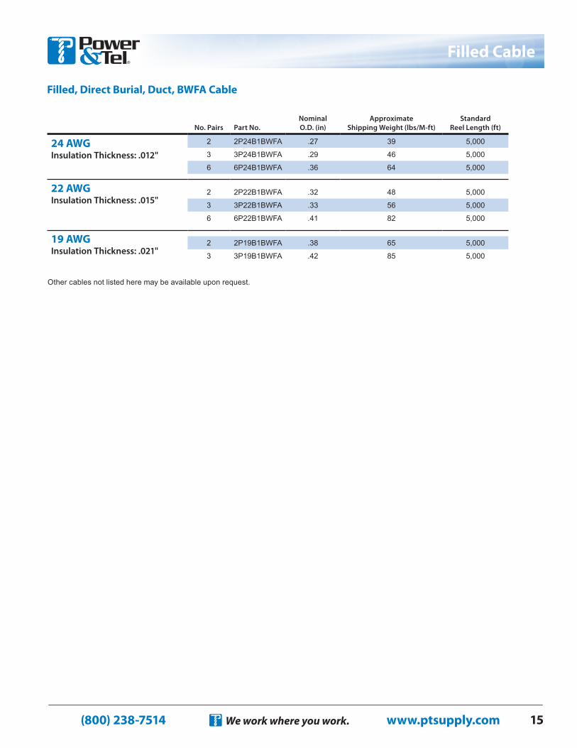
24 AWG Insulation Thickness: .012"
2 2P24B1BWFA .27 39 5,000
3 3P24B1BWFA .29 46 5,000
6 6P24B1BWFA .36 64 5,000
22 AWG Insulation Thickness: .015"
2 2P22B1BWFA .32 48 5,000
3 3P22B1BWFA .33 56 5,000
6 6P22B1BWFA .41 82 5,000
19 AWG Insulation Thickness: .021"
2 2P19B1BWFA .38 65 5,000
3 3P19B1BWFA .42 85 5,000
Filled, Direct Burial, Duct, BWFA Cable
(800) 238-7514 www.ptsupply.comWe work where you work.16
Drop & Distribution Wire
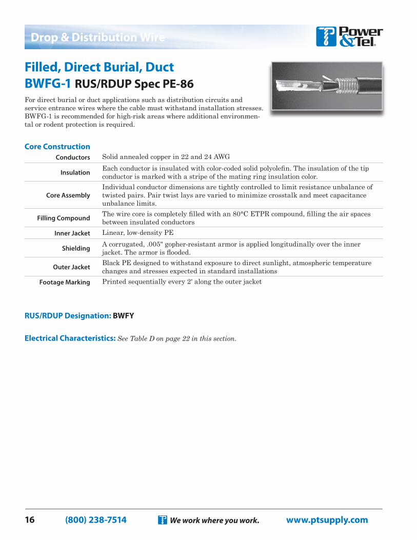
Filled, Direct Burial, Duct BWFG-1 RUS/RDUP Spec PE-86For direct burial or duct applications such as distribution circuits and service entrance wires where the cable must withstand installation stresses. BWFG-1 is recommended for high-risk areas where additional environmen-tal or rodent protection is required.
RUS/RDUP Designation: BWFY
Electrical Characteristics: See Table D on page 22 in this section.
Conductors Solid annealed copper in 22 and 24 AWG
Insulation Each conductor is insulated with color-coded solid polyolefin. The insulation of the tip conductor is marked with a stripe of the mating ring insulation color.
Core AssemblyIndividual conductor dimensions are tightly controlled to limit resistance unbalance of twisted pairs. Pair twist lays are varied to minimize crosstalk and meet capacitance unbalance limits.
Filling Compound The wire core is completely filled with an 80°C ETPR compound, filling the air spaces between insulated conductors
Inner Jacket Linear, low-density PE
Shielding A corrugated, .005" gopher-resistant armor is applied longitudinally over the inner jacket. The armor is flooded.
Outer Jacket Black PE designed to withstand exposure to direct sunlight, atmospheric temperature changes and stresses expected in standard installations
Footage Marking Printed sequentially every 2' along the outer jacket
Core Construction
(800) 238-7514 www.ptsupply.comWe work where you work. 17
Drop & Distribution Wire
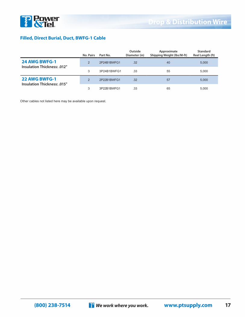
Filled, Direct Burial, Duct, BWFG-1 Cable
Other cables not listed here may be available upon request.
No. Pairs Part No.Outside
Diameter (in)Approximate
Shipping Weight (lbs/M-ft)Standard
Reel Length (ft)
24 AWG BWFG-1 Insulation Thickness: .012"
2 2P24B1BWFG1 .32 40 5,000
3 3P24B1BWFG1 .33 55 5,000
22 AWG BWFG-1 Insulation Thickness: .015"
2 2P22B1BWFG1 .32 57 5,000
3 3P22B1BWFG1 .33 65 5,000
(800) 238-7514 www.ptsupply.comWe work where you work.18
Drop & Distribution Wire
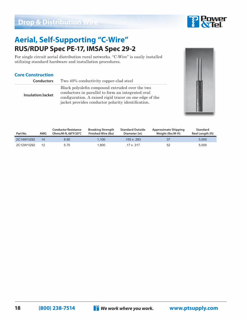
Aerial, Self-Supporting “C-Wire” RUS/RDUP Spec PE-17, IMSA Spec 29-2For single circuit aerial distribution rural networks. “C-Wire” is easily installed utilizing standard hardware and installation procedures.
Conductors Two 40% conductivity copper-clad steel
Insulation/Jacket
Black polyolefin compound extruded over the two conductors in parallel to form an integrated oval configuration. A raised rigid tracer on one edge of the jacket provides conductor polarity identification.
Core Construction
Part No. AWGConductor Resistance Ohms/M-ft, 68°F/20°C
Breaking Strength Finished Wire (lbs)
Standard Outside Diameter (in)
Approximate Shipping Weight (lbs/M-ft)
Standard Reel Length (ft)
2C14W1I292 14 8.90 1,100 .155 x .283 37 5,000
2C12W1I292 12 5.70 1,800 .17 x .317 52 5,000
(800) 238-7514 www.ptsupply.comWe work where you work. 19
Drop & Distribution Wire
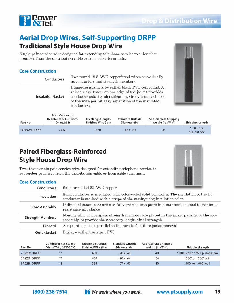
Aerial Drop Wires, Self-Supporting DRPP Traditional Style House Drop Wire
Paired Fiberglass-Reinforced Style House Drop WireTwo, three or six-pair service wire designed for extending telephone service to subscriber premises from the distribution cable or from cable terminals.
Single-pair service wire designed for extending telephone service to subscriber premises from the distribution cable or from cable terminals.
Part No.Conductor Resistance Ohms/M-ft, 68°F/20°C
Breaking Strength Finished Wire (lbs)
Standard Outside Diameter (in)
Approximate Shipping Weight (lbs/M-ft) Shipping Length
2P22B1DRPP 17 400 .20 x .40 40 1,000' coil or 750' pull-out box
3P22B1DRPP 17 450 .28 x .44 54 600' or 1000' coil
6P22B1DRPP 18 365 .27 x .50 80 400' or 1,000' coil
Conductors Two round 18.5 AWG copper/steel wires serve dually as conductors and strength members
Insulation/Jacket
Flame-resistant, all-weather black PVC compound. A raised ridge tracer on one edge of the jacket provides conductor polarity identification. Grooves on each side of the wire permit easy separation of the insulated conductors.
Core Construction
Conductors Solid annealed 22 AWG copper
Insulation Each conductor is insulated with color-coded solid polyolefin. The insulation of the tip conductor is marked with a stripe of the mating ring insulation color.
Core Assembly Individual conductors are carefully twisted into pairs in a manner designed to minimize resistance unbalance
Strength Members Non-metallic or fiberglass strength members are placed in the jacket parallel to the core assembly, to provide the necessary longitudinal strength
Ripcord A ripcord is placed parallel to the core to facilitate jacket removalOuter Jacket Black, weather-resistant PVC
Core Construction
Part No.
Max. Conductor Resistance @ 68°F/20°C
Ohms/M-ft Breaking Strength Finished Wire (lbs)
Standard Outside Diameter (in)
Approximate Shipping Weight (lbs/M-ft) Shipping Length
2C18W1DRPP 24.50 570 .15 x .29 31 1,000' coil pull-out box
(800) 238-7514 www.ptsupply.comWe work where you work.20
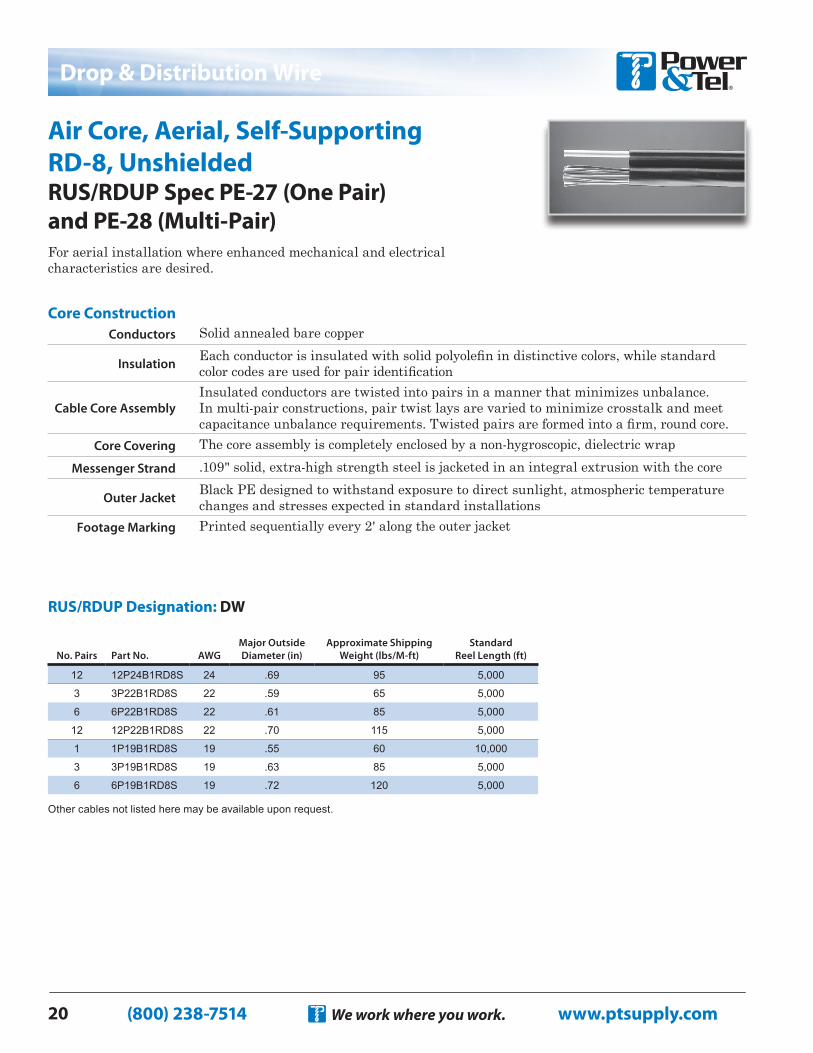
Air Core, Aerial, Self-Supporting RD-8, Unshielded RUS/RDUP Spec PE-27 (One Pair) and PE-28 (Multi-Pair)For aerial installation where enhanced mechanical and electrical characteristics are desired.
Drop & Distribution Wire
Conductors Solid annealed bare copper
Insulation Each conductor is insulated with solid polyolefin in distinctive colors, while standard color codes are used for pair identification
Cable Core AssemblyInsulated conductors are twisted into pairs in a manner that minimizes unbalance. In multi-pair constructions, pair twist lays are varied to minimize crosstalk and meet capacitance unbalance requirements. Twisted pairs are formed into a firm, round core.
Core Covering The core assembly is completely enclosed by a non-hygroscopic, dielectric wrapMessenger Strand .109" solid, extra-high strength steel is jacketed in an integral extrusion with the core
Outer Jacket Black PE designed to withstand exposure to direct sunlight, atmospheric temperature changes and stresses expected in standard installations
Footage Marking Printed sequentially every 2' along the outer jacket
Core Construction
RUS/RDUP Designation: DW
Other cables not listed here may be available upon request.
No. Pairs Part No. AWGMajor Outside Diameter (in)
Approximate Shipping Weight (lbs/M-ft)
Standard Reel Length (ft)
12 12P24B1RD8S 24 .69 95 5,000
3 3P22B1RD8S 22 .59 65 5,000
6 6P22B1RD8S 22 .61 85 5,000
12 12P22B1RD8S 22 .70 115 5,000
1 1P19B1RD8S 19 .55 60 10,000
3 3P19B1RD8S 19 .63 85 5,000
6 6P19B1RD8S 19 .72 120 5,000
(800) 238-7514 www.ptsupply.comWe work where you work. 21
Electrical Characteristics Tables
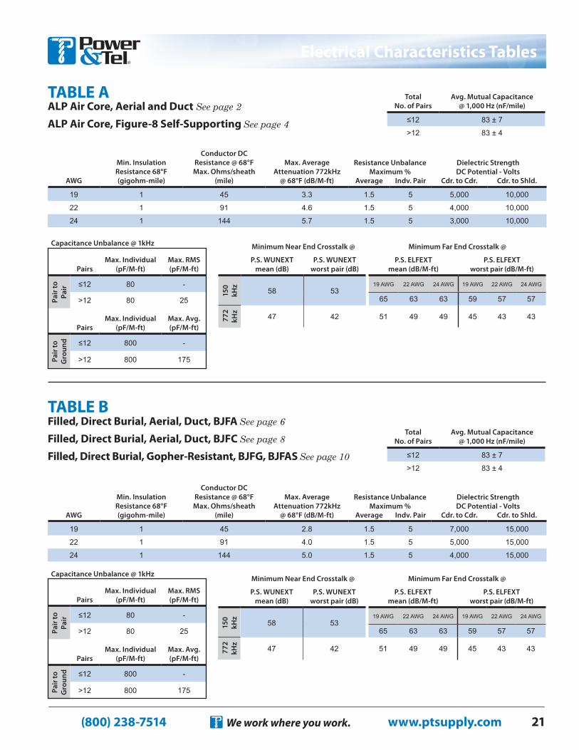
ALP Air Core, Aerial and Duct See page 2
ALP Air Core, Figure-8 Self-Supporting See page 4
TABLE A
Filled, Direct Burial, Aerial, Duct, BJFA See page 6
Filled, Direct Burial, Aerial, Duct, BJFC See page 8
Filled, Direct Burial, Gopher-Resistant, BJFG, BJFAS See page 10
TABLE B
Minimum Near End Crosstalk @ Minimum Far End Crosstalk @
P.S. WUNEXT mean (dB)
P.S. WUNEXT worst pair (dB)
P.S. ELFEXT mean (dB/M-ft)
P.S. ELFEXT worst pair (dB/M-ft)
150
kHz
58 5319 AWG 22 AWG 24 AWG 19 AWG 22 AWG 24 AWG
65 63 63 59 57 57
772
kH
z
47 42 51 49 49 45 43 43
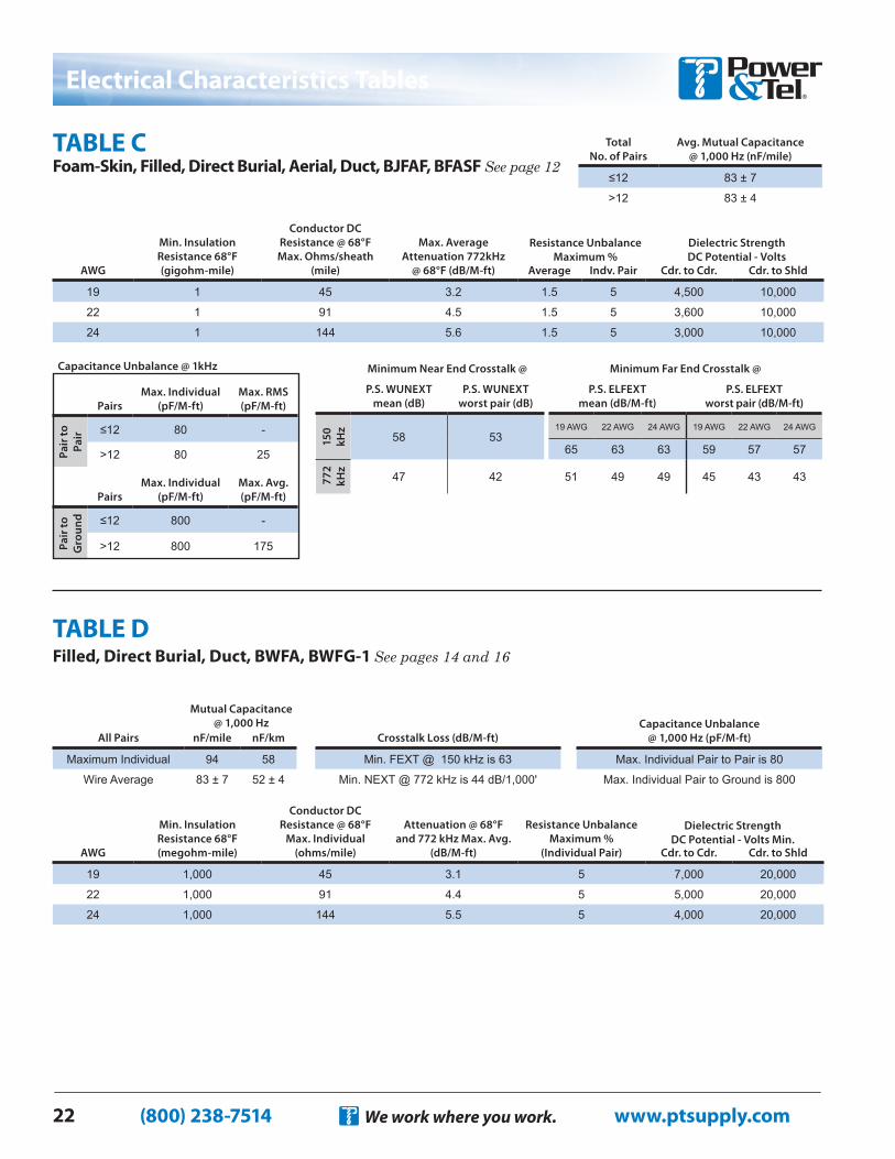
Total No. of Pairs
Avg. Mutual Capacitance @ 1,000 Hz (nF/mile)
≤12 83 ± 7
>12 83 ± 4
PairsMax. Individual
(pF/M-ft)Max. RMS (pF/M-ft)
Pair
to
Pair ≤12 80 -
>12 80 25
PairsMax. Individual
(pF/M-ft)Max. Avg. (pF/M-ft)
Pair
to
Gro
und ≤12 800 -
>12 800 175
Capacitance Unbalance @ 1kHzMinimum Near End Crosstalk @ Minimum Far End Crosstalk @
P.S. WUNEXT mean (dB)
P.S. WUNEXT worst pair (dB)
P.S. ELFEXT mean (dB/M-ft)
P.S. ELFEXT worst pair (dB/M-ft)
150
kHz
58 5319 AWG 22 AWG 24 AWG 19 AWG 22 AWG 24 AWG
65 63 63 59 57 57
772
kH
z
47 42 51 49 49 45 43 43
Total No. of Pairs
Avg. Mutual Capacitance @ 1,000 Hz (nF/mile)
≤12 83 ± 7
>12 83 ± 4
AWG
Min. Insulation Resistance 68°F (gigohm-mile)
Conductor DC Resistance @ 68°F Max. Ohms/sheath
(mile)
Max. Average Attenuation 772kHz
@ 68°F (dB/M-ft) Average Indv. Pair Cdr. to Cdr. Cdr. to Shld.
19 1 45 3.3 1.5 5 5,000 10,000
22 1 91 4.6 1.5 5 4,000 10,000
24 1 144 5.7 1.5 5 3,000 10,000
Dielectric Strength DC Potential - Volts
Resistance Unbalance Maximum %
AWG
Min. Insulation Resistance 68°F (gigohm-mile)
Conductor DC Resistance @ 68°F Max. Ohms/sheath
(mile)
Max. Average Attenuation 772kHz
@ 68°F (dB/M-ft) Average Indv. Pair Cdr. to Cdr. Cdr. to Shld.
19 1 45 2.8 1.5 5 7,000 15,000
22 1 91 4.0 1.5 5 5,000 15,000
24 1 144 5.0 1.5 5 4,000 15,000
Resistance Unbalance Maximum %
Dielectric Strength DC Potential - Volts
PairsMax. Individual
(pF/M-ft)Max. RMS (pF/M-ft)
Pair
to
Pair ≤12 80 -
>12 80 25
PairsMax. Individual
(pF/M-ft)Max. Avg. (pF/M-ft)
Pair
to
Gro
und ≤12 800 -
>12 800 175
Capacitance Unbalance @ 1kHz
(800) 238-7514 www.ptsupply.comWe work where you work.22
Filled, Direct Burial, Duct, BWFA, BWFG-1 See pages 14 and 16TABLE D
All Pairs nF/mile nF/km
Maximum Individual 94 58
Wire Average 83 ± 7 52 ± 4
Mutual Capacitance @ 1,000 Hz
AWG
Min. Insulation Resistance 68°F (megohm-mile)
Conductor DC Resistance @ 68°F
Max. Individual (ohms/mile)
Attenuation @ 68°F and 772 kHz Max. Avg.
(dB/M-ft)
Resistance Unbalance Maximum %
(Individual Pair) Cdr. to Cdr. Cdr. to Shld
19 1,000 45 3.1 5 7,000 20,000
22 1,000 91 4.4 5 5,000 20,000
24 1,000 144 5.5 5 4,000 20,000
Dielectric Strength DC Potential - Volts Min.
Crosstalk Loss (dB/M-ft)
Min. FEXT @ 150 kHz is 63
Min. NEXT @ 772 kHz is 44 dB/1,000'
Capacitance Unbalance @ 1,000 Hz (pF/M-ft)
Max. Individual Pair to Pair is 80
Max. Individual Pair to Ground is 800
AWG
Min. Insulation Resistance 68°F (gigohm-mile)
Conductor DC Resistance @ 68°F Max. Ohms/sheath
(mile)
Max. Average Attenuation 772kHz
@ 68°F (dB/M-ft) Average Indv. Pair Cdr. to Cdr. Cdr. to Shld
19 1 45 3.2 1.5 5 4,500 10,000
22 1 91 4.5 1.5 5 3,600 10,000
24 1 144 5.6 1.5 5 3,000 10,000
Minimum Near End Crosstalk @ Minimum Far End Crosstalk @
P.S. WUNEXT mean (dB)
P.S. WUNEXT worst pair (dB)
P.S. ELFEXT mean (dB/M-ft)
P.S. ELFEXT worst pair (dB/M-ft)
150
kHz
58 5319 AWG 22 AWG 24 AWG 19 AWG 22 AWG 24 AWG
65 63 63 59 57 57
772
kH
z
47 42 51 49 49 45 43 43
Total No. of Pairs
Avg. Mutual Capacitance @ 1,000 Hz (nF/mile)
≤12 83 ± 7
>12 83 ± 4
TABLE C Foam-Skin, Filled, Direct Burial, Aerial, Duct, BJFAF, BFASF See page 12
Dielectric Strength DC Potential - Volts
Resistance Unbalance Maximum %
PairsMax. Individual
(pF/M-ft)Max. RMS (pF/M-ft)
Pair
to
Pair ≤12 80 -
>12 80 25
PairsMax. Individual
(pF/M-ft)Max. Avg. (pF/M-ft)
Pair
to
Gro
und ≤12 800 -
>12 800 175
Capacitance Unbalance @ 1kHz
Electrical Characteristics Tables