Embed Size (px)
Citation preview

OUTPUT INTERFACE353156 – Microprocessor
Asst. Prof. Dr. Choopan Rattanapoka and Asst. Prof. Dr. Suphot Chunwiphat

ARM Memory Structure
AHB = Advanced High-Performance Bus Start at memory address 0xF000
0000
APB = Advanced Peripheral Bus Start at memory address 0xE000
0000Memory access also reading/ writing a sequence of bytes, so use loads for input, stores for output
• Called “Memory Mapped Input/Output”
• A portion of the address space dedicated to communication paths to Input or Output devices (no memory there)

GPIO
GPIO (General Purpose Input/Output) We can use GPIO as an Input or an Output
port Input : input digital/analog signal to
Microprocessor Output : digital output signal to devices.
IN ARM7 2 legacy ports (Port 0, Port 1) Each port has 32 pins (P0.4 means Port 0
pin 4)

LPC 2388 Board

LPC 2388 Board (Available Port) Port 0
P0.0, P0.1 (2 pins continuous) P0.4 – P0.9 (6 pins continuous) P0.12 – P0.18 (7 pins continuous) P0.24 – P0.31 (8 pins continuous)
Port 1 P1.19 – P1.31 (13 pins continuous)

Control Register on GPIO Port There are 4 abstract registers to control GPIO port
IODIR (GPIO Port Direction Control Register) To control either GPIO port is an input port (0) or output port(1) We use IODIR0 for Port0, and IODIR1 for Port1
IOPIN (GPIO Pin Value Register) To read current port status We use IOPIN0 for Port0, and IOPIN1 for Port1
IOSET (GPIO Port Output Set Register) To write data “1” to the specific port to make output logic to
“1” IOSET0 for Port0, and IOSET1 for Port1
IOCLR (GPIO Port Output Clear Register) To write data “1” to the specific port to make output logic to
“0” IOCLR0 for Port0, and IOCLR1 for Port1

Example 1 : Setting a port as output
unsigned int P0_9 = 0x00000100;
IODIR0 = P0_9;
IOSET0 = P0_9;
IOCLR0 = P0_9;
Define a variable P0_9 to store value
0x00000100
Set Port 0.9 as an output port
Set logic “1” as output of Port 0.9
Set logic “0” as output of Port 0.9

Example: 2 LEDs Blink (1)
2 LEDs connected to P0.29 connected to P0.30
We want 2 LEDs blink at the same time.

Example: 2 LEDs Blink (2)
#include “LPC23XX.h”
int main(void) {
unsigned int P0_29 = (1 << 29);
unsigned int P0_30 = (1 << 30);
int i;
IODIR0 = P0_29 | P0_30;
while(1) {
IOSET0 = P0_29 | P0_30;
for(i = 0; i < 10000; i++);
IOCLR0 = P0_29 | P0_30;
for(i = 0; i < 10000; i++)
}
}

Example 3: 7-Segment (1)
Suppose, we use common cathode 7-segment Logic 1 at either a, b, c, d, e, f, g or dp
will light up that LED. We will use
P1.31 for a P1.30 for b P1.29 for c P1.28 for d P1.27 for e P1.26 for f P1.25 for g P1.24 for dp

Example 3: 7-Segment(2)
Display
P1.31(a)
P1.30(b)
P1.29(c)
P1.28(d)
P1.27
(e)
P1.26(f)
P1.25
(g)
P1.24(.)
Hex Value
0 1 1 1 1 1 1 0 0 0xFC000000
1 0 1 1 0 0 0 0 0 0x60000000
2
3
4
5
6
7
8
9
. Let’s complete the table

Example 3 : 7-Segment (3)
Code for displaying “0” on 7-segment.
#include “LPC23XX.h”
int main(void) {
unsigned int P1_24TO31 = 0xFF000000;
IODIR1 = P1_24TO31;
IOCLR1 = P1_24TO31;
IOSET1 = 0xFC000000;
while(1);
}

SWITCH-CASE
SWITCH-CASE in C is used for selecting a multiple (constant) choices.
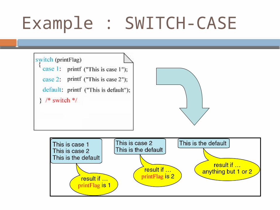
Example : SWITCH-CASE

Example : SWITCH-CASE with Break

Example : 7-Segment with SWITCH
#include “LPC23XX.h”
int main(void) {
unsigned int P1_24TO31 = 0xFF000000;
int num = 0;
IODIR1 = P1_24TO31;
IOCLR1 = P1_24TO31;
switch(num) {
case 0 : IOSET1= 0xFC000000; break;
case 1 : IOSET1 = 0x60000000; break;
…
}
while(1);
}

Assignment 9
Write a program in C for microcontroller to display a number on
7-segment as a
following sequence “0” “1” “2” “0”
“1” “2” “0” … Don’t forget to wait for
a moment before moving to the next number
Don’t forget to clear last output before setting the new one
Use “switch-case” and some loop statements for this program