Embed Size (px)
Citation preview
Outline
• Introductory Remarks
• Statecharts Syntactic and Semantic Basics.
• Modeling the Wrist Watch
[short break anticipated]
• Statecharts Odds&Ends.
• Statecharts as Formal Development Method
• Concluding Remarks
[short break anticipated]
• Project possibilities.
• Exercise (the air conditioner example)
IT University of Copenhagen 2
Reactive Systems
• Transformational programs compute a result for the given inputparameters (eg. compilers)
• Reactive programs (Pnueli,Harel,1985): constantly listen toincoming input and produce outputs in reaction to those (eg.embedded systems, user interfaces)
• Reactive system receives external stimuli from sensors and affectsenvironment using actuators. Sensor may be a button, actuatormay be a display.
• Discrete Reactive Systems ignore the continuity of time and work inlock steps.
• Synchrony Hypothesis is an assumption that reaction of a discretesystem takes no time (outputs are available immediately). Inpractice it means that systems reaction is faster than frequency ofenvironment events.
IT University of Copenhagen 3
Modeling Reactive Systems
with IAR visualSTATE Statecharts
Andrzej Wa,sowski([email protected])
http://www.mini.pw.edu.pl/~wasowski/
27 November 2003
IT University of Copenhagen
Outline
• Introductory Remarks
• Statecharts Syntactic and Semantic Basics.
• Modeling the Wrist Watch
[short break anticipated]
• Statecharts Odds&Ends.
• Statecharts as Formal Development Method
• Concluding Remarks
[short break anticipated]
• Project possibilities.
• Exercise (the air conditioner example)
IT University of Copenhagen 1
Outline
• Introductory Remarks
• Statecharts: Syntactic and Semantic Basics
• Modeling the Wrist Watch
[short break anticipated]
• Statecharts Odds&Ends.
• Statecharts as Formal Development Method
• Concluding Remarks
[short break anticipated]
• Project possibilities.
• Exercise (the air conditioner example)
IT University of Copenhagen 6
Syntactic Trivia
B
A
C
Dα
β
δ
γ(P )
D superstateA, B and C basic statesA,C: a xor-decomposition of Dβ leaves all substates of D
Invariants:1. active(B) xor active(D)2. active(D) ≡ active(A) xor active(C)
• An extension of finite state machines and transition diagrams.
– FSM: a single state active and a single transition taken at a time.
– statecharts: multiple active states and concurrent transitions.
• Labels: Events and outputs possibly parameterized (value passing).
• Transition relation represented by arrows.
• Hierarchy relation represented by nesting of states.
Harel87:Fig.2/p.234
IT University of Copenhagen 7
Architecture of Reactive System
SKELETONCONTROL
Driver Loop
Act
uato
rs
Sen
sors
DRIVER
DRIVER
DRIVER
DRIVER
HANDLER
HANDLER
HANDLER
HANDLER
HANDLER DRIVER
DRIVER
DRIVER
DRIVER
DRIVERAnother RTOS processHardwareHardware Software
on
off
• Control algorithm (skeleton).
• Brown parts are small and relatively easy.
• Sometimes multiple processes are avoided in favour of the loop.
• In some cases it is even possible to give up the RTOS entirely.
IT University of Copenhagen 4
An Abridged History of Statecharts
• Statecharts: a visual modeling language mostly focused on discretetime systems.
• Proposed by David Harel in 1984 and implemented inSTATEMATE.
• Accepted as one of the notations in UML (1996).
• BeoLogic uses a variant of statecharts as a specification language intheir modeling tool visualSTATE.
• Presently visualSTATE is maintained by IAR Systems (Danishdivision).
• A Multitude of tools supports statecharts: visualSTATE, Rhapsody,ArgoUML, Rational Rose...
CREDITS: The vast part of this lecture is based on the exampletaken from the classic paper on statecharts:
“Statecharts: A Visual Formalism For Complex Systems”David Harel, 1987
IT University of Copenhagen 5
Orthogonality
B
C
E
G
F
AY
D
α
δ
µ
γα β G
• All transitions are fired by events.
• Note one transition guarded on active substate of concurrent state.
• States A and D are called regions (or or-states).
• State Y is called a concurrent state (or and-state).
• Note the significant gain in succinctness (wrt to productautomaton).
Harel87:Fig.19/p.242
IT University of Copenhagen 10
Outline
• Introductory Remarks
• Statecharts: Syntactic and Semantic Basics
• Modeling the Wrist Watch
[short break anticipated]
• Statecharts Odds&Ends.
• Statecharts as Formal Development Method
• Concluding Remarks
[short break anticipated]
• Project possibilities.
• Exercise (the air conditioner example)
IT University of Copenhagen 11
Initial States
A
D
D
A
Eδ1
δ0
• Initial states and initial markers
– D is the initial state of E
– A is the initial state of D
– is the initial marker or connector(in UML).
• δ0,δ1 enter initial configuration of D and E.
IT University of Copenhagen 8
Entry Actions
entry: dout(e1, . . . , en)D
entry: aout()A
δ1
Eentry: eout(e1, . . . , en)
Transition’s δ1 own actions are executed first, followed by a sequence
eout(); dout(...); aout();
Outputs are provided as C functions available in seperate file. Outputsmay be parameterized. See later on expressions.
IT University of Copenhagen 9

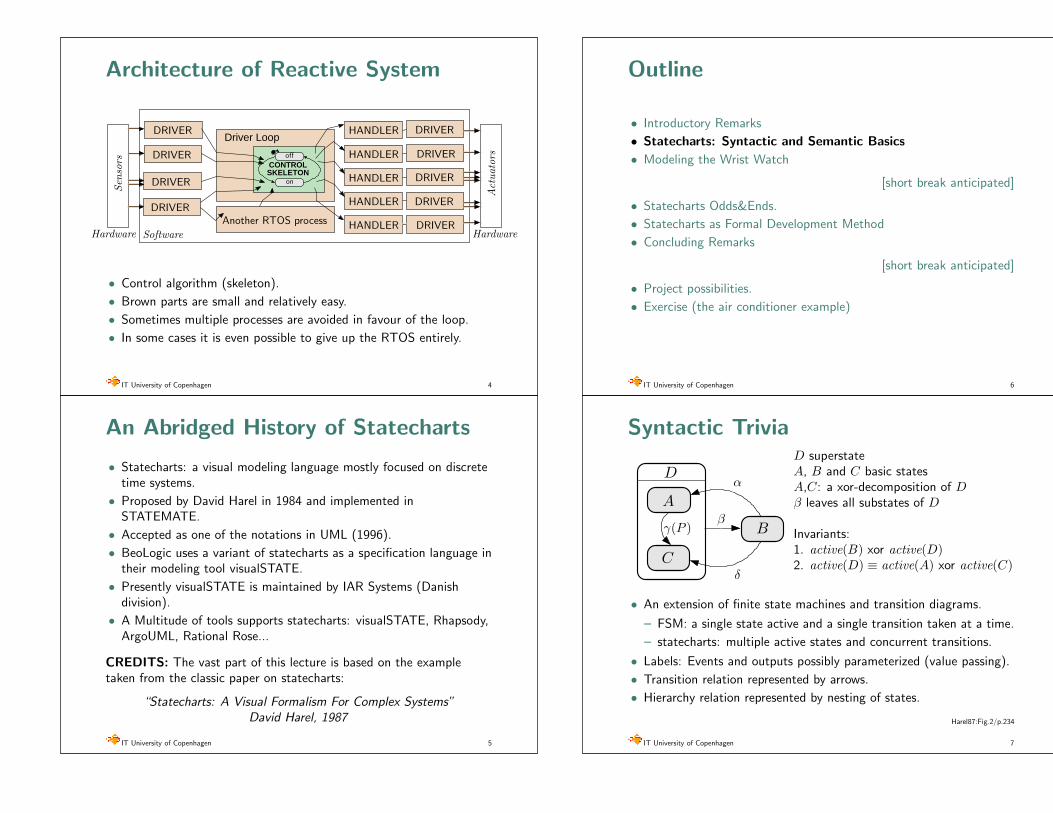
Alarm Activation
alarm1 beeps
alarm2 beeps
both beep
displays
alarms beep
T hits T1
[alarm1 enabled ∧ (alarm2 disabled ∨T1 6= T2)]
T hits T2
or 30s in alarms beepany button pressed
T hits T1
[alarm1 enabled ∧ (alarm2 disabled ∨T1 6= T2)]
[alarm1 enabled ∧ (alarm2 enabled ∧T1 = T2)]
Unfortunately not formal enough for implementation and verification.
Harel87:Fig.8/p.237
IT University of Copenhagen 14
Alarm Activation (II)
What shall we refine to move towards a formal model in visualSTATE?
• Undefined clocks (variables)
– internal int T1; // second of the day to activate the alarm
• Imprecise events:
– button events: a() b() c() d()
– Any button pressed → AnyButton() = a ∨ b ∨ c ∨ d
– 30s in alarms-beep → BeepTimeout()
– T hits T1 → external event T hits T1()
• Actions to set up timers for time related events:
– T hits T1() is fired by an external RTOS process setup ininitialization and controlled whenever setting are changed.
– Set up BeepTimeout() timer whenever alarms beep is entered
• Missing states for enabledness of alarms (independent component)
• Eliminate disjunctions from guards (not allowed in visualSTATE)
IT University of Copenhagen 15
The Running Example
A model of a wrist watch.
Day of montham/pm [12/24] mode
Timer running
Chime (beep on hour)
Alarm 1
Time display
Alarm 2
Display and beeper are the outputs of the watch device.
Harel87:Fig.7/p.236
IT University of Copenhagen 12
The Running Example (II)
Buttons, events and behaviours.
Display mode
Date
Set
Start/Stop
Our goal is to assign exact meaning to button (inputs).
Harel87:Fig.7/p.236
IT University of Copenhagen 13
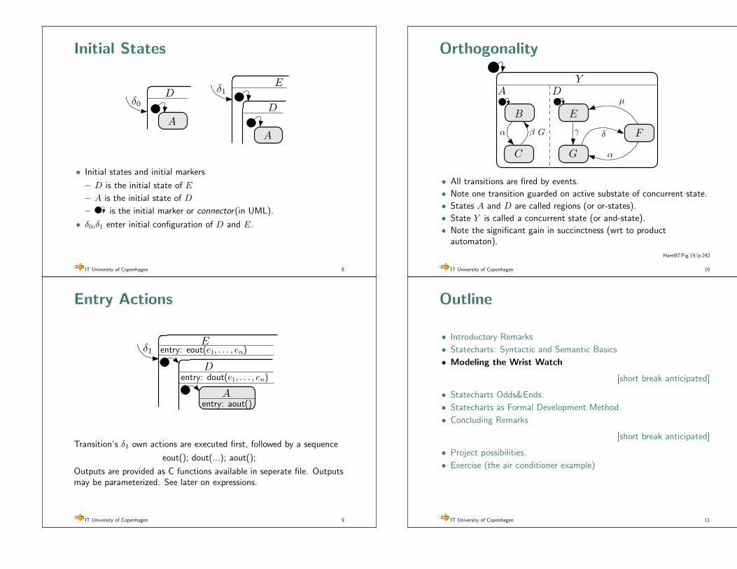
Refining Displays (II)
Note the StartTimer(DateTimeout,120) action, generatingDateTimout after 120 units.
Harel87:Fig.9/p.237
IT University of Copenhagen 18
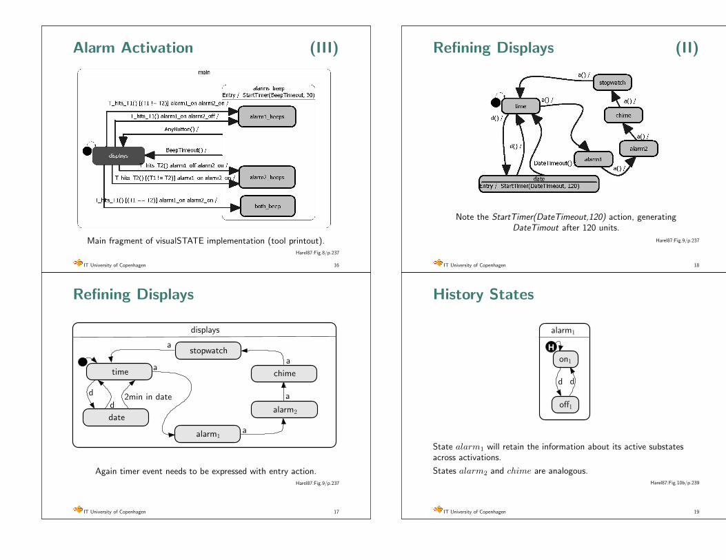
History States
Hon1
off1
d d
alarm1
State alarm1 will retain the information about its active substatesacross activations.
States alarm2 and chime are analogous.Harel87:Fig.10b/p.239
IT University of Copenhagen 19
Alarm Activation (III)
Main fragment of visualSTATE implementation (tool printout).Harel87:Fig.8/p.237
IT University of Copenhagen 16
Refining Displays
stopwatch
time
date
chime
alarm2
alarm1
displays
a
a
2min in dated
d
a
a
a
Again timer event needs to be expressed with entry action.Harel87:Fig.9/p.237
IT University of Copenhagen 17

Update Modes for Time (II)
Note the transitions going out to and coming from upper level.Harel87:Fig.15/p.241
IT University of Copenhagen 22
Update Modes for Time (III)
Harel87:Fig.14/p.240
IT University of Copenhagen 23
Alarms and Chime Setup
Alarms and chime can be activated and deactivated if display is in theproper mode.
[Note a slight design change with respect to the original paper, toavoid relying on semantic subtleties.]
IT University of Copenhagen 20
Update Modes for Time
Harel87:Fig.13/p.240
IT University of Copenhagen 21
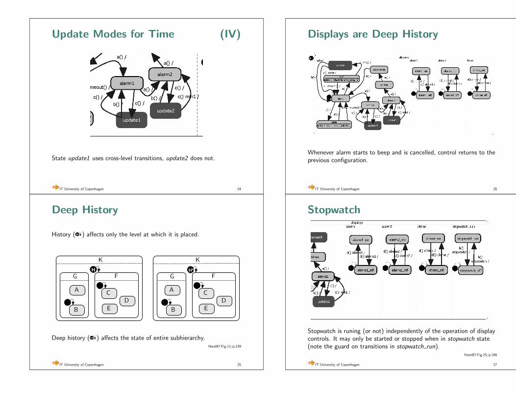
Displays are Deep History
Whenever alarm starts to beep and is cancelled, control returns to theprevious configuration.
IT University of Copenhagen 26
Stopwatch
Stopwatch is runing (or not) independently of the operation of displaycontrols. It may only be started or stopped when in stopwatch state(note the guard on transitions in stopwatch run).
Harel87:Fig.25/p.246
IT University of Copenhagen 27
Update Modes for Time (IV)
State update1 uses cross-level transitions, update2 does not.
IT University of Copenhagen 24
Deep History
History ( H ) affects only the level at which it is placed.
H
B
A C
ED
G F
K
H*
A
B
C
ED
G F
K
Deep history ( H* ) affects the state of entire subhierarchy.Harel87:Fig.11/p.239
IT University of Copenhagen 25
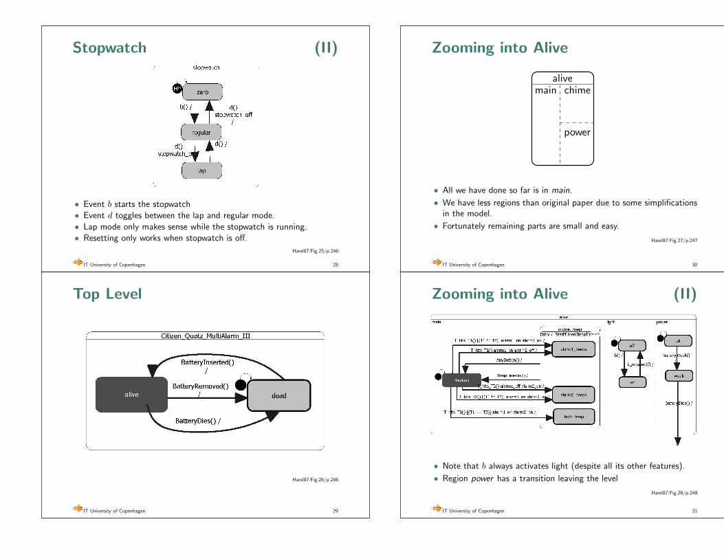
Zooming into Alive
main chime
power
alive
• All we have done so far is in main.
• We have less regions than original paper due to some simplificationsin the model.
• Fortunately remaining parts are small and easy.
Harel87:Fig.27/p.247
IT University of Copenhagen 30
Zooming into Alive (II)
• Note that b always activates light (despite all its other features).
• Region power has a transition leaving the level
Harel87:Fig.28/p.248
IT University of Copenhagen 31
Stopwatch (II)
• Event b starts the stopwatch
• Event d toggles between the lap and regular mode.
• Lap mode only makes sense while the stopwatch is running.
• Resetting only works when stopwatch is off.
Harel87:Fig.25/p.246
IT University of Copenhagen 28
Top Level
Harel87:Fig.26/p.246
IT University of Copenhagen 29

Transitions Revisited
Let us summarize the syntax of transitions.
• Transitions are labeled with conditions and actions:
B
A
condition side: events and guards
action side: outputs and local signals
e() C F / f(x + 1) ˆs
• Condition part: event/signal/event-group, positive/negativecondition, guard (C expression)
• Action part: function calls, assignments to variables and triggeringsignals
IT University of Copenhagen 34
Abstract vs Physical States
• Our model has been constructed in terms of states and transitions.
• These states were abstract. For instance we have not specified anyrelation between the state alarm1.on1 and the fact that the alarmindicator on display is visible.
Hon1
off1
d d
alarm1
?• Such abstract models are useful for analysis of systems but not for
development of real programs!
IT University of Copenhagen 35
Outline
• Introductory Remarks
• Statecharts: Syntactic and Semantic Basics
• Modeling the Wrist Watch
[short break anticipated]
• Statecharts Odds&Ends
• Statecharts as Formal Development Method
• Concluding Remarks
[short break anticipated]
• Project possibilities.
• Exercise (the air conditioner example)
IT University of Copenhagen 32
Signal Communication
• Signals are means of asynchronous communication.
• Signals are similar to events but are not visible for environments.
• Signals may be triggered in any action (on transitons, on entry andexit to states).
• Signals are placed in the condition of a transition in the same wayas events.
• In visualSTATE signals are global (i.e. directed to the entiresystem).
• System with signals works in two stage steps:
– Microstep: apply one event or signal to the model put all signalsproduced in a signal queue
– Macrostep pop a signal from a queue and run a microstep.Iterate until the queue is empty.
• Only macrosteps are observable from external perspective.
IT University of Copenhagen 33

Outline
• Introductory Remarks
• Statecharts: Syntactic and Semantic Basics
• Modeling the Wrist Watch
[short break anticipated]
• Statecharts Odds&Ends
• Statecharts as Formal Development Method
• Concluding Remarks
[short break anticipated]
• Project possibilities.
• Exercise (the air conditioner example)
IT University of Copenhagen 38
Formal Development
• Abstract modeling.
• Automatic model verification.
• Tool-supported debugging (simulation and monitored execution).
• Tool-supported program synthesis (code generation).
• Systematic test of implementation [in progress].
IT University of Copenhagen 39
Abstract vs Physical States (II)
• Abstract state is the state in the model.
• Physical state is the state of the device or environment.
• In models used for synthesis of systems abstract states need to berelated to physical states.
• One typical way to achieve this is by use of entry and exit actions.
H
off1
Entry / ShowAlrm1(1)Exit / ShowAlrm1(0)
on1
dd
alarm1
IT University of Copenhagen 36
visualSTATE Odds&Ends
• Model constants
• Model variables with restricted domains
• External vs Internal variables
• Internal rules
• Do reactions
• Parameterized events may pass the value of sensor readout.
• Entry/exit actions can be hidden (prevents cluttering of diagrams)
�δ0
D
A �
IT University of Copenhagen 37

Outline
• Introductory Remarks
• Statecharts: Syntactic and Semantic Basics
• Modeling the Wrist Watch
[short break anticipated]
• Statecharts Odds&Ends
• Statecharts as Formal Development Method
• Concluding Remarks
[short break anticipated]
• Project possibilities.
• Exercise (the air conditioner example)
IT University of Copenhagen 42
Reactive Programming Agora
• Synchronous Languages — a family of languages based on thestrong synchrony hypothesis, namely that outputs are producedinstantenously with inputs. They present a somewhat unsualprogramming style, but exhibit clean and compact mathematicalsemantics and are easier to model check. Esterel is the mainimperative dialect. Lustre and Signal follow the functionalprogramming style, while Argos is the visual incarnation of thesemantics, rather similar to stateacharts.
• Timed Triggered Languages (eg. Giotto) — based on periodic tasksand data-flow like networks.
• Timed Automata — specifications of systems with continuous time.
• Hybrid Automata — specifications of systems with continuouscontrol.
• So far it seems that statecharts are the only language becomingpopular in mainstream development tools.
IT University of Copenhagen 43
visualSTATE model checker
Model checker automatically verifies if following hold in the model:
• No unused components [states, variables]
• No unreachable guards. It must be possible to enable all of theguards in the system. This means that there must exist a reachablestate for each guard g that enables this guard. Unreachable guardsmean dead code (dead transitions).
• No conflicting transitions.
• No deadlocks.
• No illegal operations. Arithmetic operations should be checked foroverflow and illegal operations such as division by zero.
• No divergent behavior. If the signal queue is used then themacrostep should always be finite.
• No overflow of the signal queue.
IT University of Copenhagen 40
visualSTATE Code Generator
• visualSTATE contains a translator of models into C programs.
• Program implementing the control algorithm is generatedautomatically.
• Programmer should provide
– Code for external C functions, drivers and handlers
– Main loop feeding external events to the system
– and a RTOS (if needed).
• The generated code has very modest memory requirements. Anorder of 50 words of RAM is sufficient for execution. ROM usagefor a model of 200 transitions (rather complex) is in order of 10kb.
IT University of Copenhagen 41
Thank you forYour attention.
IT University of Copenhagen 44
![Test of applicability of multitemporal differential interferometry analysis to landslide investigations in peri-urban areas * Wasowski J. [1], Bovenga](https://img.pdfslide.us/doc/110x75/5514036e550346ec488b4a28/test-of-applicability-of-multitemporal-differential-interferometry-analysis-to-landslide-investigations-in-peri-urban-areas-wasowski-j-1-bovenga.jpg)