Embed Size (px)
Citation preview

TECHNICAL & SERVICE MANUALOUTDOOR UNIT : GRF148MR5I
GRF198MR5IGRF248MR5IGRF318MR5I
GRF148MR5I
GRF318MR5I
GRF198MR5IGRF248MR5I
DC INVERTER MULTI-SYSTEM AIR CONDITIONEROutdoor Model No.
GRF148MR5I
GRF198MR5I
GRF248MR5I
GRF318MR5I
Capacity
4.0kW
5.6kW
6.8kW
8.0kW
Product Code No.
GRF148MR5IAA (1 852 349 49)
GRF198MR5IAA (1 852 349 50)
GRF248MR5IAA (1 852 349 51)
GRF318MR5IAB
REFERENCE NO. SM04/2012
< Applicable Indoor Units >
Wall mounted type
For details about the combination, refer to "Unit Combination Table" in the Appendix ofthis manual.
MCAF78MR5IMCAF98MR5IMCAF128MR5IMCAF188R5IMCAF248R5I
NOTE
Destination: Europe
RoHS
WARNING
• This product does not contain any hazardous substances prohibited by the RoHS Directive.
• You are requested to use RoHS compliant parts for maintenance or repair.• You are requested to use lead-free solder.
FILE NO.
Do not vent R410A into atmosphere : R410A is a fluorinated greenhouse gas,covered by Kyoto Protocol, with a Global Warming Potential (GWP) = 1975.
F-GAS REGULATION (EC) No 842 / 2006

When Wiring
ELECTRICAL SHOCK CAN CAUSE SEVERE PERSONAL INJURY OR DEATH. ONLY A QUALIFIED, EXPERIENCED ELECTRICIAN SHOULD ATTEMPT TO WIRE THIS SYSTEM.
SPECIAL PRECAUTIONS
This symbol refers to a hazard or unsafe practice which can result in severe personal injury or death.
This symbol refers to a hazard or unsafe practice which can result in personal injury or product or property damage.
CAUTION
CAUTION
WARNING
WARNING
Important! Please Read Before StartingThis air conditioning system meets strict safety and operating standards. As the installer or service person, it is an important part of your job to install or service the system so it operates safely and efficiently.
For safe installation and trouble-free operation, you must:
Carefully read this instruction booklet before beginning.Follow each installation or repair step exactly as shown.Observe all local, state, and national electrical codes.Pay close attention to all warning and caution notices given in this manual.
If Necessary, Get HelpThese instructions are all you need for most installation sites and maintenance conditions. If you require help for a special problem, contact our sales/service outlet or your certified dealer for additional instructions.
In Case of Improper InstallationThe manufacturer shall in no way be responsible for improper installation or maintenance service, including failure to follow the instructions in this document.
Do not supply power to the unit until all wiring and tubing are completed or reconnected and checked.Highly dangerous electrical voltages are used in this system. Carefully refer to the wiring diagram and these instructions when wiring. Improper connections and inadequate grounding can cause accidental injury or death.Ground the unit following local electrical codes.Connect all wiring tightly. Loose wiring may cause overheating at connection points and a possible fire hazard.Install a protective leakage breaker depending on the installation location (especially a damp or humid location). If a leakage breaker is not installed, electric shock can occur.
When Transporting
Be careful when picking up and moving the indoor and outdoor units. Get a partner to help, and bend your knees when lifting to reduce strain on your back. Sharp edges or thin aluminum fins on the air conditioner can cut your fingers.
When Installing
In a Ceiling or WallMake sure the ceiling/wall is strong enough to hold the unit’s weight. It may be necessary to construct a strong wood or metal frame to provide added support.In a RoomProperly insulate any tubing run inside a room to prevent "sweating" that can cause dripping and water damage to walls and floors.In Moist or Uneven LocationsUse a raised concrete pad or concrete blocks to provide a solid, level foundation for the outdoor unit. This prevents water damage and abnormal vibration.In an Area with High WindsSecurely anchor the outdoor unit down with bolts and a metal frame. Provide a suitable air baffle. In a Snowy Area (for Heat Pump-type Systems)Install the outdoor unit on a raised platform that is higher than drifting snow. Provide snow vents.
When Connecting Refrigerant Tubing
Use the flare method for connecting tubing.Apply refrigerant lubricant to the matching surfaces of the flare and union tubes before connecting them, then tighten the nut with a torque wrench for a leak-free connection.Check carefully for leaks before starting the test run.
When Servicing
Turn the power off at the main power box (mains) before opening the unit to check or repair electrical parts and wiring.Keep your fingers and clothing away from any moving parts.Clean up the site after you finish, remembering to check that no metal scraps or bits of wiring have been left inside the unit being serviced.
Others
Ventilate any enclosed areas when installing or testing the refrigeration system. Escaped refrigerant gas, on contact with fire or heat, can produce dangerously toxic gas. Confirm upon completing installation that no refrigerant gas is leaking. If escaped gas comes in contact with a stove, gas water heater, electric room heater or other heat source, it can produce dangerously toxic gas.
•
•
••
•
••
•
•
•
•
•
•
2

Table of Contents
APPLICABLE INDOOR UNITS
1. OPERATING RANGE
2. SPECIFICATIONS2-1. Unit Specifications 2-2. Major Component Specifications 2-3. Other Component Specifications
3. DIMENSIONAL DATA
4. REFRIGERANT FLOW DIAGRAM4-1. Refrigerant Flow Diagram
5. PERFORMANCE DATA5-1. Temperature Charts
6. ELECTRICAL DATA6-1. Electric Wiring Diagrams
7. FUNCTIONS7-1. Explanation of Functions7-2. Protective Functions
8. TROUBLESHOOTING8-1. Precautions before Performing Inspection or Repair8-2. Trouble Diagnosis by Error Monitor Lamps8-3. Checking the Outdoor System8-4. Trouble Diagnosis of Each Part8-5. Trouble Diagnosis of Fan Motor
9. REFRIGERANT R410A: SPECIAL PRECAUTIONS WHEN SERVICING UNIT9-1. Characteristics of New Refrigerant R410A9-2. Checklist before Servicing9-3. Tools Specifically for R410A9-4. Tubing Installation Procedures9-5. In Case of Compressor Malfunction9-6. In Case Refrigerant is Leaking9-7. Charging Additional Refrigerant9-8. Retro-Fitting Existing Systems
5
6
71115
16
20
24
41
4549
5253545558
5959616162646565
....................................................................................................
...................................................................................................................
...........................................................................................................................................................................................................................................................................................
...................................................................................................................
...................................................................................................
............................................................................................................
....................................................................................................
...............................................................................................................................................................................................................
....................................................................................................................................
................................................................................................................................................................................................................................................................................
............................................................................................................................................................................
............................................................................................................................................................................................
..........................................................................................................................................................................................................................................................................
............................................................................................
Page
3

APPENDIX INSTALLATION INSTRUCTIONS A-1
-
.............................................................................
Page
4

APPLICABLE INDOOR UNITS
GRF148MR5I
Multi-Outdoor Unit
Indoor Unit
YES YES YES NO NO
GRF198MR5I YES YES YES YES NO
GRF248MR5I YES YES YES YES YES
GRF318MR5I
2-Room
2-Room
4-Room
4-Room YES YES YES YES YES
MCAF78MR5I MCAF98MR5I MCAF128MR5I MCAF188R5I MCAF248R5I
NOTE 1. The table lists the wall-mounted type of indoor units as representative models.
2. For details on the applicable indoor units other than the wall-mounted type, refer to the catalog.
5

6
1. OPERATING RANGE
Temperature Indoor Air Intake Temp. Outdoor Air Intake Temp.
Maximum 32 °C D.B. / 23 °C W.B. 43 °C D.B. Cooling
Minimum 19 °C D.B. / 14 °C W.B. -5 °C W.B. (*1)
Maximum 27 °C D.B. 24 °C D.B. / 18 °C W.B. Heating
Minimum 16 °C D.B. -D.B. / -15 °C W.B.
(*1) 0 °C D.B. : When combined with MCAF188R5I, MCAF248R5I

2. SPECIFICATIONS2-1. Unit SpecificationsOutdoor Unit GRF148MR5IIndoor Unit MCAF98MR5I × 2
DATA SUBJECT TO CHANGE WITHOUT NOTICE.
CompressorRefrigerant / Amount charged at shipment kgRefrigerant Control
4.1925
4.013,600
( 2.0 to 5.0 )( 6,800 to 17,100 )
Shipping Volume
Cooling
1,900
Cooling
NetShipping
Package Dimensions
Weight
Height × Width × Depth
Height × Width × Depthkgkg
m3
mm
mm
220 to 240V Single-Phase 50Hz
198 to 264
Dimensions & Weight (Outdoor Unit)
Refrigerant Tubing Connections
Unit Dimensions
Electrical Rating
Air Circulation (High)
WPower Input
VA
Available Voltage RangeRunning Amperes
Narrow tubeWide tube
Refrigerant mm (in.)Tube Diameter mm (in.)
42.045.00.22
569 × 790 × 285
645 × 920 × 385
6.35 (1/4") × 29.52 (3/8") × 2
mMax. allowable tubing length per unitFlare Type
20
R410A / 1.7Electric Expansion Valve
DC Twin Rotary (Inverter)
dB-A
Fan Speeds Auto (Hi, Me, Lo)Control Microprocessor
Features (Outdoor Unit)
C.O.P.
kW
Performance
%Power Factor 98
W/W -
Power Source
BTU/hCapacity
m3/h
E.E.R. W/W 4.32
230VVoltage Rating
Type
Number of Connectable Indoor Units
6.15Max. Capacity of Operating Indoor Units kW
Number of Operatable Indoor Units
4.515,400
( 2.2 to 5.5 )( 7,500 to 18,800 )
Heating
1,900
Compressor Locked Rotor Amperes A 14.5
4.1925
Heating
98
4.86-
Operation Sound Hi 47 48
Remarks:1. The Values shown in performance section and electrical rating section above are based on the following unit combination.
For other combination unit, please refer to the "Unit Combination Tables" in this manual. Indoor Unit : MCAF98MR5I 2units Outdoor Unit : GRF148MR5I 1unit2. Rating conditions are: Cooling : Indoor air temp. 27°C D.B. / 19°C W.B. Heating : Indoor air temp. 20°C D.B.
Outdoor air temp. 35°C D.B. / 24°C W.B. Outdoor air temp. 7°C D.B. / 6°C W.B.
2-Room Multi Outdoor Unit
2
2
7

Outdoor Unit GRF198MR5IIndoor Unit MCAF98MR5I × 1 + MCAF188R5I × 1
DATA SUBJECT TO CHANGE WITHOUT NOTICE.
CompressorRefrigerant / Amount charged at shipment kgRefrigerant Control
7.521,695
5.619,100
( 2.1 to 6.8 )( 7,200 to 23,200 )
Shipping Volume
Cooling
2,900
Cooling
NetShipping
Package Dimensions
Weight
Height × Width × Depth
Height × Width × Depthkgkg
m3
mm
mm
220 to 240V Single-Phase 50Hz
198 to 264
Dimensions & Weight (Outdoor Unit)
Refrigerant Tubing Connections
Unit Dimensions
Electrical Rating
Air Circulation (High)
WPower Input
VA
Available Voltage RangeRunning Amperes
Narrow tubeWide tube
Refrigerant mm (in.)Tube Diameter mm (in.)
65.069.00.38
740 × 900 × 320
868 × 1,050 × 423
6.35 (1/4") × 29.52 (3/8") × 2
mMax. allowable tubing length per unitFlare Type
25
R410A / 2.8Electric Expansion Valve
DC Twin Rotary (Inverter)
dB-A
Fan Speeds Auto (Hi, Me, Lo)Control Microprocessor
Features (Outdoor Unit)
C.O.P.
kW
Performance
%Power Factor 98
W/W -
Power Source
BTU/hCapacity
m3/h
E.E.R. W/W 3.30
230VVoltage Rating
2-Room Multi Outdoor UnitType
2Number of Connectable Indoor Units
8.65Max. Capacity of Operating Indoor Units kW
2Number of Operatable Indoor Units
7.324,900
( 2.4 to 8.4 )( 8,200 to 28,700 )
Heating
2,900
Compressor Locked Rotor Amperes A 14.5
7.701,735
Heating
98
4.21-
Operation Sound Hi 50 52
Remarks:1. The Values shown in performance section and electrical rating section above are based on the following unit combination.
For other combination unit, please refer to the "Unit Combination Tables" in this manual. Indoor Unit : MCAF98MR5I 1unit + MCAF188R5I 1unit Outdoor Unit : GRF198MR5I 1unit2. Rating conditions are: Cooling : Indoor air temp. 27°C D.B. / 19°C W.B. Heating : Indoor air temp. 20°C D.B.
Outdoor air temp. 35°C D.B. / 24°C W.B. Outdoor air temp. 7°C D.B. / 6°C W.B.
8

Outdoor Unit GRF248MR5IIndoor Unit MCAF98MR5I × 3
DATA SUBJECT TO CHANGE WITHOUT NOTICE.
CompressorRefrigerant / Amount charged at shipment kgRefrigerant Control
8.872,000
6.823,200
( 2.9 to 8.1 )( 9,900 to 27,600 )
Shipping Volume
Cooling
2,900
Cooling
NetShipping
Package Dimensions
Weight
Height × Width × Depth
Height × Width × Depthkgkg
m3
mm
mm
220 to 240V Single-Phase 50Hz
198 to 264
Dimensions & Weight (Outdoor Unit)
Refrigerant Tubing Connections
Unit Dimensions
Electrical Rating
Air Circulation (High)
WPower Input
VA
Available Voltage RangeRunning Amperes
Narrow tubeWide tube
Refrigerant mm (in.)Tube Diameter mm (in.)
65.069.00.38
740 × 900 × 320
868 × 1,050 × 423
6.35 (1/4") × 49.52 (3/8") × 3 + 12.7 (1/2") × 1
mMax. allowable tubing length per unitFlare Type
25
R410A / 2.8Electric Expansion Valve
DC Twin Rotary (Inverter)
dB-A
Fan Speeds Auto (Hi, Me, Lo)Control Microprocessor
Features (Outdoor Unit)
C.O.P.
kW
Performance
%Power Factor 98
W/W -
Power Source
BTU/hCapacity
m3/h
E.E.R. W/W 3.40
230VVoltage Rating
4-Room Multi Outdoor UnitType
4Number of Connectable Indoor Units
12.2Max. Capacity of Operating Indoor Units kW
3Number of Operatable Indoor Units
8.629,300
( 3.4 to 9.0 )( 11,600 to 30,700 )
Heating
2,900
Compressor Locked Rotor Amperes A 14.5
8.872,000
Heating
98
4.30-
Operation Sound Hi 50 52
Remarks:1. The Values shown in performance section and electrical rating section above are based on the following unit combination.
For other combination unit, please refer to the "Unit Combination Tables" in this manual. Indoor Unit : MCAF98MR5I 3units Outdoor Unit : GRF248MR5I 1unit2. Rating conditions are: Cooling : Indoor air temp. 27°C D.B. / 19°C W.B. Heating : Indoor air temp. 20°C D.B.
Outdoor air temp. 35°C D.B. / 24°C W.B. Outdoor air temp. 7°C D.B. / 6°C W.B.
9
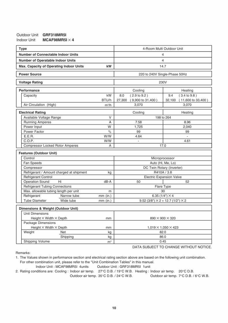
Outdoor Unit GRF318MR5IIndoor Unit MCAF98MR5I × 4
DATA SUBJECT TO CHANGE WITHOUT NOTICE.
CompressorRefrigerant / Amount charged at shipment kgRefrigerant Control
7.581,725
8.027,300
( 2.9 to 9.2 )( 9,900 to 31,400 )
Shipping Volume
Cooling
3,070
Cooling
NetShipping
Package Dimensions
Weight
Height × Width × Depth
Height × Width × Depthkgkg
m3
mm
mm
220 to 240V Single-Phase 50Hz
198 to 264
Dimensions & Weight (Outdoor Unit)
Refrigerant Tubing Connections
Unit Dimensions
Electrical Rating
Air Circulation (High)
WPower Input
VA
Available Voltage RangeRunning Amperes
Narrow tubeWide tube
Refrigerant mm (in.)Tube Diameter mm (in.)
82.086.00.45
890 × 900 × 320
1,019 × 1,050 × 423
6.35 (1/4") × 49.52 (3/8") × 2 + 12.7 (1/2") × 2
mMax. allowable tubing length per unitFlare Type
30
R410A / 3.8Electric Expansion Valve
DC Twin Rotary (Inverter)
dB-A
Fan Speeds Auto (Hi, Me, Lo)Control Microprocessor
Features (Outdoor Unit)
C.O.P.
kW
Performance
%Power Factor 99
W/W -
Power Source
BTU/hCapacity
m3/h
E.E.R. W/W 4.64
230VVoltage Rating
4-Room Multi Outdoor UnitType
4Number of Connectable Indoor Units
14.7Max. Capacity of Operating Indoor Units kW
4Number of Operatable Indoor Units
9.432,100
( 3.4 to 9.8 )( 11,600 to 33,400 )
Heating
3,070
Compressor Locked Rotor Amperes A 17.0
8.962,040
Heating
99
4.61-
Operation Sound Hi 50 52
Remarks:1. The Values shown in performance section and electrical rating section above are based on the following unit combination.
For other combination unit, please refer to the "Unit Combination Tables" in this manual. Indoor Unit : MCAF98MR5I 4units Outdoor Unit : GRF318MR5I 1unit2. Rating conditions are: Cooling : Indoor air temp. 27°C D.B. / 19°C W.B. Heating : Indoor air temp. 20°C D.B.
Outdoor air temp. 35°C D.B. / 24°C W.B. Outdoor air temp. 7°C D.B. / 6°C W.B.
10

Outdoor Unit GRF148MR5I
2-2-1. Outdoor Unit
Control PCB
Control Circuit Fuse ControlsPart No.
Microprocessor250V 25A
CB-CMRV1424EH
DATA SUBJECT TO CHANGE WITHOUT NOTICE.
cc
WHT - BLU :RED - WHT :
BLU - RED :77.577.5
77.5
Micro FVAC
External Finish Acrylic baked-on enamel finish
FV50S ... 350
--
Internal ControllerYes
Aluminum Plate Fin / Copper Tube2
13 Face Area m2
mm0.452
CoilRowsFin Pitch
Heat Exchanger Coil
DAJ12-55J71-CR ... 1
Compressor Oil ... Amount
8
50750 / 750
Ohm
DC Motor
TypeCompressor Model / Nominal Output
Compressor
Coil Resistance (Ambient Temp. 20 °C) Ohm
DC Twin Rotary (Hermetic)C-6RVN93H0M / 1,000W
R - S :S - T :T - R :
0.4820.4820.482
CT (Peak current cut-off control)Compressor Discharge Temp. ControlOperation cut-off control in abnormal ambient Temp.
Safety Device
Micro FVAC
Run Capacitor
Crankcase Heater
YesYesYes
Overload Relay CS-7L115ModelOperation Temp. Open : 115 °C, Close : 95 °C
---
1 ... D420
FanPropeller
Q'ty ... Dia. mmType
TypeOver-Current Protection
Fan Motor
Nominal OutputCoil Resistance
Safety Device
Run Capacitor
TypeModel ... Q'tyNo. of Poles
W
2-2. Major Component Specifications
(Ambient Temp. 20 °C)
Rough Measure RPM (Cool:Hi / Heat:Hi)
11

Outdoor Unit GRF198MR5I
Control PCB
Control Circuit Fuse ControlsPart No.
Microprocessor250V 25A
CB-CMRV1924EH
cc FV50S ... 900Compressor Oil ... Amount
TypeCompressor Model / Nominal Output
Compressor
Coil Resistance (Ambient Temp. 20 °C) Ohm
DC Twin Rotary (Hermetic)5KD240XAB21 / 1,700W
U - V :V - W :W - U :
0.7200.7080.726
CT (Peak current cut-off control)Compressor Discharge Temp. ControlOperation cut-off control in abnormal ambient Temp.
Safety Device
Micro FVAC
Run Capacitor
Crankcase Heater
YesYesYes
Overload Relay CS-7LN115ModelOperation Temp. Open : 115 °C, Close : 100 °C
--
230V 25W
1 ... D460
FanPropeller
Q'ty ... Dia. mmType
DATA SUBJECT TO CHANGE WITHOUT NOTICE.
-
Micro FVAC
External Finish Acrylic baked-on enamel finish
--
Internal ControllerYesYes
Aluminum Plate Fin / Copper Tube2
1.4 Face Area 0.595
CoilRows
Heat Exchanger Coil
SIC-71FW-D490-1 ... 1
8
90750 / 750
Ohm
DC Motor
TypeOver-Current ProtectionOver-Heat Protection
(Ambient Temp. 20 °C)
Fan Motor
Nominal OutputCoil Resistance
Safety Device
Rough Measure RPM (Cool:Hi / Heat:Hi)
Run Capacitor
TypeModel ... Q'tyNo. of Poles
W
m2
mmFin Pitch
12

Outdoor Unit GRF248MR5I
Control PCB
Control Circuit Fuse ControlsPart No.
Microprocessor250V 25A
CB-CMRV2444EH
cc FV50S ... 900Compressor Oil ... Amount
TypeCompressor Model / Nominal Output
Compressor
Coil Resistance (Ambient Temp. 20 °C) Ohm
DC Twin Rotary (Hermetic)5KD240XAB21 / 1,700W
U - V :V - W :W - U :
0.7200.7080.726
CT (Peak current cut-off control)Compressor Discharge Temp. ControlOperation cut-off control in abnormal ambient Temp.
Safety Device
Micro FVAC
Run Capacitor
Crankcase Heater
YesYesYes
Overload Relay CS-7LN115ModelOperation Temp. Open : 115 °C, Close : 100 °C
--
230V 25W
1 ... D460
FanPropeller
Q'ty ... Dia. mmType
DATA SUBJECT TO CHANGE WITHOUT NOTICE.
-
Micro FVAC
External Finish Acrylic baked-on enamel finish
--
Internal ControllerYesYes
Aluminum Plate Fin / Copper Tube2
1.4 Face Area 0.595
CoilRows
Heat Exchanger Coil
SIC-71FW-D490-1 ... 1
8
90750 / 750
Ohm
DC Motor
TypeOver-Current ProtectionOver-Heat Protection
(Ambient Temp. 20 °C)
Fan Motor
Nominal OutputCoil Resistance
Safety Device
Rough Measure RPM (Cool:Hi / Heat:Hi)
Run Capacitor
TypeModel ... Q'tyNo. of Poles
W
m2
mmFin Pitch
13

Outdoor Unit GRF318MR5I
Control PCB
Control Circuit Fuse ControlsPart No.
Microprocessor250V 25A
CB-CMRV3144EH
cc FV50S ... 1,200Compressor Oil ... Amount
TypeCompressor Model / Nominal Output
Compressor
Coil Resistance (Ambient Temp. 20 °C) Ohm
DC Twin Rotary (Hermetic)5JD420XAB22 / 3,000W
U - V :V - W :W - U :
0.4350.4410.452
CT (Peak current cut-off control)Compressor Discharge Temp. ControlOperation cut-off control in abnormal ambient Temp.
Safety Device
Micro FVAC
Run Capacitor
Crankcase Heater
YesYesYes
Overload Relay CS-7LN115ModelOperation Temp. Open : 115 °C, Close : 100 °C
--
230V 25W
1 ... D460
FanPropeller
Q'ty ... Dia. mmType
DATA SUBJECT TO CHANGE WITHOUT NOTICE.
-
Micro FVAC
External Finish Acrylic baked-on enamel finish
--
Internal ControllerYesYes
Aluminum Plate Fin / Copper Tube2
1.4 Face Area 0.723
CoilRows
Heat Exchanger Coil
SIC-71FW-D490-1 ... 1
8
90750 / 750
Ohm
DC Motor
TypeOver-Current ProtectionOver-Heat Protection
(Ambient Temp. 20 °C)
Fan Motor
Nominal OutputCoil Resistance
Safety Device
Rough Measure RPM (Cool:Hi / Heat:Hi)
Run Capacitor
TypeModel ... Q'tyNo. of Poles
W
m2
mmFin Pitch
14

2-3. Other Component Specifications
00 10 20 30 40 50 60 70 80 90
40
60
80
100
120
140
160
180
200
20
Res
ista
nce
(k
oh
m)
Temperature (°C)
40
35
30
25
20
15
10
5
0-20 -15 -10 -5 0 5 10 15 20
Temperature (°C)
Res
ista
nce
(k
oh
m)
Outdoor air temp sensor
Outdoor heat exchanger sensor
AW / AN sensor
BW / BN sensor
CW / CN sensor
DW / DN sensor
TKS295B
TKS292B
TKS292B
TKS292B
TKS292B
TKS292B
Model No.of sensorSensor Name
1
1
1/1
1/1
0
0
1
1
1/1
1/1
0
0
Quantity of Sensor
1
1
1/1
1/1
1/1
1/1
1
1
1/1
1/1
1/1
1/1
GRF148MR5I GRF198MR5I GRF248MR5I GRF318MR5I
Sensor Name
Compressor temp sensor TKS293B
Model No.of sensor
1 1
Quantity of Sensor
1 1
GRF148MR5I GRF198MR5I GRF248MR5I GRF318MR5I
15

295
608 85
790 70
46
336
310
285
4-ID:23.6ID:18
2-ID:12
569
15
7012
2158
70
14246
Wide tube service valvedia.9.52 (3/8") × 2
Narrow tube service valvedia.6.35 (1/4") × 2
Unit: mm
3. DIMENSIONAL DATAOutdoor Unit GRF148MR5I
16

293
608 136
12
900 85
35
369
345
320
ID:1
8
5-ID
:23.
6
740
18
7511
3150
72
11451
Wide tube service valvedia.9.52 (3/8") × 2
Narrow tube service valvedia.6.35 (1/4") × 2
Outdoor Unit GRF198MR5I
Unit: mm
17

293
608 136
12
35
369
345
320
ID:1
8
5-ID
:23.
6
900 85
740
18
7570
11315
072
70
11451
70
70
Wide tube service valvedia.9.52 (3/8") × 3
Narrow tube service valvedia.6.35 (1/4") × 4
Wide tube service valvedia.12.70 (1/2") × 1
Outdoor Unit GRF248MR5I
Unit: mm
18

293
608 136
12
35
369
345
320
ID:1
8
5-ID
:23.
6
900 85
890
18
7570
11315
073
70
11451
70
70
Wide tube service valvedia.9.52 (3/8") × 2
Narrow tube service valvedia.6.35 (1/4") × 4
Wide tube service valvedia.12.70 (1/2") × 2
Outdoor Unit GRF318MR5I
Unit: mm
19

4. REFRIGERANT FLOW DIAGRAM4-1. Refrigerant Flow DiagramOutdoor Unit GRF148MR5I
Insulation of Refrigerant Tubing
Because capillary tubing is used in the outdoor unit, both thewide and narrow tubes of this air conditioner become cold. Toprevent heat loss and wet floors due to dripping ofcondensation, both tubes must be well insulated with a proper insulation material. The thickness of the insulationshould be a min. 8 mm.
After a tube has been insulated,never try to bend it into a narrowcurve because it can cause the tubeto break or crack.
Wide tube
Thickness:Min. 8 mm
Insulation
Narrow tube
Thickness:Min. 8 mm
IMPORTANT
CAUTION
Com
pres
sor
4-wayvalve
Mainaccumulator
Subaccumulator
Service valve onnarrow tube
Service valve onwide tube
Wide tube
BN
AN
BW
AW
O.D.9.52mm
O.D.9.52mm
Narrow tubeO.D.6.35mm
O.D.6.35mm
Hea
t exc
hang
er
Capillarytube for split flow
Cooling cycle
Heating cycle
Defrosting cycle
Indoor unit Outdoor unit
Defrost valvefor hot gas bypass
Strainer
S
M
M
Electricexpansionvalve
Muffler
20

Narrow tubeO.D.6.35mm
O.D.6.35mm
Outdoor Unit GRF198MR5I
Insulation of Refrigerant Tubing
Because capillary tubing is used in the outdoor unit, both thewide and narrow tubes of this air conditioner become cold. Toprevent heat loss and wet floors due to dripping ofcondensation, both tubes must be well insulated with a proper insulation material. The thickness of the insulationshould be a min. 8 mm.
After a tube has been insulated,never try to bend it into a narrowcurve because it can cause the tubeto break or crack.
Wide tube
Thickness:Min. 8 mm
Insulation
Narrow tube
Thickness:Min. 8 mm
IMPORTANT
CAUTION
Com
pres
sor
4-wayvalve
Mainaccumulator
Subaccumulator
Service valve onnarrow tube
Service valve onwide tube
Wide tube
BN
AN
BW
AW
O.D.9.52mm
O.D.9.52mm
Hea
t exc
hang
er
Cooling cycle
Heating cycle
Defrosting cycle
Indoor unit Outdoor unit
Defrost valvefor hot gas bypass
Strainer
S
M
M
Electricexpansionvalve
Header
Header
21

Outdoor Unit GRF248MR5I
Insulation of Refrigerant Tubing
Because capillary tubing is used in the outdoor unit, both thewide and narrow tubes of this air conditioner become cold. Toprevent heat loss and wet floors due to dripping ofcondensation, both tubes must be well insulated with a proper insulation material. The thickness of the insulationshould be a min. 8 mm.
After a tube has been insulated,never try to bend it into a narrowcurve because it can cause the tubeto break or crack.
Wide tube
Thickness:Min. 8 mm
Insulation
Narrow tube
Thickness:Min. 8 mm
IMPORTANT
CAUTION
Com
pres
sor
4-wayvalve
Mainaccumulator
Subaccumulator
Service valve onnarrow tube
Service valve onwide tube
Wide tube
DN
CN
BN
AN
DW
CW
BW
AW
O.D.9.52mm
O.D.9.52mm
O.D.9.52mm
O.D.12.7mm
Narrow tubeO.D.6.35mm
O.D.6.35mm
O.D.6.35mm
O.D.6.35mm
Hea
t exc
hang
er
Cooling cycle
Heating cycle
Defrosting cycle
Indoor unit Outdoor unit
Defrost valvefor hot gas bypass
Strainer
S
M
M
Electricexpansionvalve
Header
Header
M
M
22

Outdoor Unit GRF318MR5I
Insulation of Refrigerant Tubing
Because capillary tubing is used in the outdoor unit, both thewide and narrow tubes of this air conditioner become cold. Toprevent heat loss and wet floors due to dripping ofcondensation, both tubes must be well insulated with a proper insulation material. The thickness of the insulationshould be a min. 8 mm.
After a tube has been insulated,never try to bend it into a narrowcurve because it can cause the tubeto break or crack.
Wide tube
Thickness:Min. 8 mm
Insulation
Narrow tube
Thickness:Min. 8 mm
IMPORTANT
CAUTION
Com
pres
sor
4-wayvalve
Mainaccumulator
Subaccumulator
Service valve onnarrow tube
Service valve onwide tube
Wide tube
DN
CN
BN
AN
DW
CW
BW
AW
O.D.9.52mm
O.D.9.52mm
O.D.12.7mm
O.D.12.7mm
Narrow tubeO.D.6.35mm
O.D.6.35mm
O.D.6.35mm
O.D.6.35mm
Hea
t exc
hang
er
Cooling cycle
Heating cycle
Defrosting cycle
Indoor unit Outdoor unit
Defrost valvefor hot gas bypass
Strainer
S
M
M
Electricexpansionvalve
Header
Header
M
M
23

5. PERFORMANCE DATA5-1. Temperature Charts
5-1-1. Temperature Charts (GRF148MR5I)
Outdoor Unit GRF148MR5I Indoor Unit MCAF78MR5I × 1
Cooling Characteristics(RH : 46%, Indoor fan speed : High fan)(230V, 50Hz)
Heating Characteristics(RH : 85%, Indoor fan speed : High fan)(230V, 50Hz)
(1) Low pressure performance chart (1) High pressure performance chart
(2) Operating current performance chart (2) Operating current performance chart
(3) Indoor discharge air performance chart (3) Indoor discharge air performance chart
• This performance chart shows operation of a single wall-mounted indoor unit. The performance chart will vary depending on the indoor unit type.
• Check each performance value in test-run mode. Electrical performance values represent a combined indoor/outdoor value.(In this case, be sure to stop all the indoor units where performance is not being checked.)
• The performance is for a tubing length of 7.5 m. If the tubing length is different, the performance chart will vary.
NOTE
Low
pre
ssur
e at
wid
e tu
be s
ervi
ce v
alve
MP
aG (
kgf/c
m2 G
)
Hig
h pr
essu
re a
t wid
e tu
be s
ervi
ce v
alve
MP
aG (
kgf/c
m2 G
)Outdoor air temperature (°C) Outdoor air temperature (°C)
30 35 40
1.4(14.2)
1.6(16.2)
1.2(12.2)
1.0(10.2)
25 -5 0 5 10 15 20 25
3.5(35.7)
3.0(30.6)
2.5(25.5)
2.0(20.4)
1.5(15.3)
Ope
ratin
g cu
rren
t (A
)
Ope
ratin
g cu
rren
t (A
)
Outdoor air temperature (°C) Outdoor air temperature (°C)
30 35 40
3
4
2
125 -5 0 5 10 15 20 25
4
3
2
1
Indo
or d
isch
arge
air
tem
pera
ture
(°C
)
Indo
or d
isch
arge
air
tem
pera
ture
(°C
)
Outdoor air temperature (°C) Outdoor air temperature (°C)
5-5 0 5 10 15 20 25
55
50
45
40
35
30
25
20
20°C
17°CIndoor air te
mp.23
Indoor air temp.23°C
Indoor air temp.23°C
20°C
17°C
30 35 40
20
25
15
10
25
2727°C
2424°C
Indoor air temp.30°CIndoor air temp.30°C
27°C
24°C
20°C
17°C
Indoor air temp.23
Indoor air temp.23°C
Indoor air temp.23°C
20°C
17°C
27°C24°C
Indoor air temp.30
Indoor air temp.30°C
Indoor air temp.30°C
27°C24°C
27°C
2424°C
Indoor air temp.30°CIndoor air temp.30°C
27°C
24°C
20°C17°C
Indoor air temp.23°CIndoor air temp.23°C
20°C17°C
Lo fan Hi fan
Lo fan Hi fan
Lo fan Hi fan
24

Cooling Characteristics(RH : 46%, Indoor fan speed : High fan)(230V, 50Hz)
Heating Characteristics(RH : 85%, Indoor fan speed : High fan)(230V, 50Hz)
(1) Low pressure performance chart (1) High pressure performance chart
(2) Operating current performance chart (2) Operating current performance chart
(3) Indoor discharge air performance chart (3) Indoor discharge air performance chart
• This performance chart shows operation of a single wall-mounted indoor unit. The performance chart will vary depending on the indoor unit type.
• Check each performance value in test-run mode. Electrical performance values represent a combined indoor/outdoor value.(In this case, be sure to stop all the indoor units where performance is not being checked.)
• The performance is for a tubing length of 7.5 m. If the tubing length is different, the performance chart will vary.
NOTE
Outdoor air temperature (°C) Outdoor air temperature (°C)
30 35 4025
Lo fan Hi fan
-5 0 5 10 15 20 25
Ope
ratin
g cu
rren
t (A
)
Ope
ratin
g cu
rren
t (A
)
Outdoor air temperature (°C) Outdoor air temperature (°C)
30 35 40
3
4
2
125
Lo fan Hi fan
-5 0 5 10 15 20 25
6
7
5
4
3
Indo
or d
isch
arge
air
tem
pera
ture
(°C
)
Indo
or d
isch
arge
air
tem
pera
ture
(°C
)
Outdoor air temperature (°C) Outdoor air temperature (°C)
5-5 0 5 10 15 20 25
60
55
50
45
40
35
30
25
20°C
17°C
Indoor air temp.23
Indoor air temp.23°C
Indoor air temp.23°C
20°C
17°C
30 35 40
20
25
15
10
25
Lo fan Hi fan
27°C
24°C
Indoor air temp.30°CIndoor air temp.30°C
27°C
24°C
20°C
17°C
Indoor air temp.23
Indoor air temp.23°C
Indoor air temp.23°C
20°C
17°C
27°C24°C
Indoor air temp.30
Indoor air temp.30°C
Indoor air temp.30°C
27°C24°C
27°C
2424°C
Indoor air temp.30Indoor air temp.30°CIndoor air temp.30°C
27°C
24°C
2020°C1717°C
Indoor air temp.23Indoor air temp.23°CIndoor air temp.23°C
20°C17°C
Outdoor Unit GRF148MR5I Indoor Unit MCAF98MR5I × 1
Low
pre
ssur
e at
wid
e tu
be s
ervi
ce v
alve
MP
aG (
kgf/c
m2 G
)
Hig
h pr
essu
re a
t wid
e tu
be s
ervi
ce v
alve
MP
aG (
kgf/c
m2 G
)
1.4(14.2)
1.6(16.2)
1.2(12.2)
1.0(10.2)
3.5(35.7)
3.0(30.6)
2.5(25.5)
2.0(20.4)
25

Cooling Characteristics(RH : 46%, Indoor fan speed : High fan)(230V, 50Hz)
Heating Characteristics(RH : 85%, Indoor fan speed : High fan)(230V, 50Hz)
(1) Low pressure performance chart (1) High pressure performance chart
(2) Operating current performance chart (2) Operating current performance chart
(3) Indoor discharge air performance chart (3) Indoor discharge air performance chart
• This performance chart shows operation of a single wall-mounted indoor unit. The performance chart will vary depending on the indoor unit type.
• Check each performance value in test-run mode. Electrical performance values represent a combined indoor/outdoor value.(In this case, be sure to stop all the indoor units where performance is not being checked.)
• The performance is for a tubing length of 7.5 m. If the tubing length is different, the performance chart will vary.
NOTE
Outdoor air temperature (°C) Outdoor air temperature (°C)
30 35 4025
Lo fan Hi fan
-5 0 5 10 15 20 25
Ope
ratin
g cu
rren
t (A
)
Ope
ratin
g cu
rren
t (A
)
Outdoor air temperature (°C) Outdoor air temperature (°C)
30 35 40
5
6
4
325
Lo fan Hi fan
-5 0 5 10 15 20 25
7
8
6
5
4
Indo
or d
isch
arge
air
tem
pera
ture
(°C
)
Indo
or d
isch
arge
air
tem
pera
ture
(°C
)
Outdoor air temperature (°C) Outdoor air temperature (°C)
5-5 0 5 10 15 20 25
65
60
55
50
45
40
35
30
20°C
17°C
Indoor air temp.23
Indoor air temp.23°C
Indoor air temp.23°C
20°C
17°C
30 35 40
20
25
15
10
25
27°C
24°C
Indoor air temp.30°CIndoor air temp.30°C
27°C
24°C
20°C
17°C
Indoor air temp.23
Indoor air temp.23°C
Indoor air temp.23°C
20°C
17°C
27°C
24°C
Indoor air temp.30
Indoor air temp.30°C
Indoor air temp.30°C
27°C
24°C
2727°C
2424°C
Indoor air temp.30Indoor air temp.30°CIndoor air temp.30°C
27°C
24°C
20°C
17°C
Indoor air temp.23°C
Indoor air temp.23°C
20°C
17°C
Outdoor Unit GRF148MR5I Indoor Unit MCAF128MR5I × 1
Lo fan Hi fan
Low
pre
ssur
e at
wid
e tu
be s
ervi
ce v
alve
MP
aG (
kgf/c
m2 G
)
Hig
h pr
essu
re a
t wid
e tu
be s
ervi
ce v
alve
MP
aG (
kgf/c
m2 G
)
1.2(12.2)
1.4(14.2)
1.0(10.2)
0.8(8.2)
4.0(40.8)
3.5(35.7)
3.0(30.6)
2.5(25.5)
26
Cooling Characteristics(RH : 46%, Indoor fan speed : High fan)(230V, 50Hz)
Heating Characteristics(RH : 85%, Indoor fan speed : High fan)(230V, 50Hz)
• This performance chart shows operation of a single wall-mounted indoor unit. The performance chart will vary depending on the indoor unit type.
• Check each performance value in test-run mode. Electrical performance values represent a combined indoor/outdoor value.(In this case, be sure to stop all the indoor units where performance is not being checked.)
• The performance is for a tubing length of 7.5 m. If the tubing length is different, the performance chart will vary.
NOTE
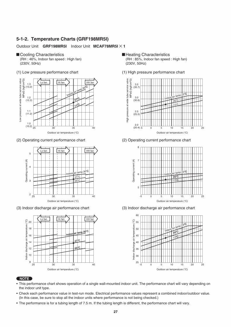
Outdoor Unit GRF198MR5I Indoor Unit MCAF78MR5I × 15-1-2. Temperature Charts (GRF198MR5I)
(1) Low pressure performance chart (1) High pressure performance chart
(2) Operating current performance chart (2) Operating current performance chart
(3) Indoor discharge air performance chart (3) Indoor discharge air performance chart
Outdoor air temperature (°C) Outdoor air temperature (°C)
30 35 4025
Lo fan Hi fan HH fan
-5 0 5 10 15 20 25
Ope
ratin
g cu
rren
t (A
)
Ope
ratin
g cu
rren
t (A
)
Outdoor air temperature (°C) Outdoor air temperature (°C)
30 35 40
4
5
3
225
Lo fan Hi fan HH fan
-5 0 5 10 15 20 25
7
8
6
5
Indo
or d
isch
arge
air
tem
pera
ture
(°C
)
Indo
or d
isch
arge
air
tem
pera
ture
(°C
)
Outdoor air temperature (°C) Outdoor air temperature (°C)
8-5 0 5 10 15 20 25
60
55
50
45
40
35
30
25
20°C
1717°C
Indoor air temp.23
Indoor air temp.23°C
Indoor air temp.23°C
20°C
17°C
30 35 40
20
18
16
14
12
10
25
Lo fan Hi fan HH fan
27°C
2424°C
Indoor air temp.30
Indoor air temp.30°C
Indoor air temp.30°C
27°C
24°C20°C
17°C
Indoor air temp.23
Indoor air temp.23°C
Indoor air temp.23°C
20°C
17°C
27°C
24°C
Indoor air temp.30Indoor air temp.30°CIndoor air temp.30°C
27°C
24°C
27°C
24°C
Indoor air temp.30°CIndoor air temp.30°C
27°C
24°C
20°C
1717°C
Indoor air temp.23Indoor air temp.23°CIndoor air temp.23°C
20°C
17°C
Low
pre
ssur
e at
wid
e tu
be s
ervi
ce v
alve
MP
aG (
kgf/c
m2 G
)
Hig
h pr
essu
re a
t wid
e tu
be s
ervi
ce v
alve
MP
aG (
kgf/c
m2 G
)
1.2(12.2)
1.3(13.2)
1.1(11.2)
1.0(10.2)
3.5(35.7)
3.0(30.6)
2.5(25.5)
2.0(20.4)
27

• This performance chart shows operation of a single wall-mounted indoor unit. The performance chart will vary depending on the indoor unit type.
• Check each performance value in test-run mode. Electrical performance values represent a combined indoor/outdoor value.(In this case, be sure to stop all the indoor units where performance is not being checked.)
• The performance is for a tubing length of 7.5 m. If the tubing length is different, the performance chart will vary.
NOTE
Outdoor Unit GRF198MR5I Indoor Unit MCAF98MR5I × 1
Cooling Characteristics(RH : 46%, Indoor fan speed : High fan)(230V, 50Hz)
Heating Characteristics(RH : 85%, Indoor fan speed : High fan)(230V, 50Hz)
(1) Low pressure performance chart (1) High pressure performance chart
(2) Operating current performance chart (2) Operating current performance chart
(3) Indoor discharge air performance chart (3) Indoor discharge air performance chart
Outdoor air temperature (°C) Outdoor air temperature (°C)
30 35 4025
Lo fan Hi fan
-5 0 5 10 15 20 25
Ope
ratin
g cu
rren
t (A
)
Ope
ratin
g cu
rren
t (A
)
Outdoor air temperature (°C) Outdoor air temperature (°C)
30 35 40
5
6
4
325
Lo fan Hi fan
-5 0 5 10 15 20 25
7
8
6
5
Indo
or d
isch
arge
air
tem
pera
ture
(°C
)
Indo
or d
isch
arge
air
tem
pera
ture
(°C
)
Outdoor air temperature (°C) Outdoor air temperature (°C)
10-5 0 5 10 15 20 25
60
55
50
45
40
35
30
25
20°C
17°C
Indoor air temp.23Indoor air temp.23°CIndoor air temp.23°C
20°C
17°C
30 35 40
20
18
16
14
12
25
Lo fan Hi fan
27°C
24°C
Indoor air temp.30
Indoor air temp.30°C
Indoor air temp.30°C
27°C
24°C20°C
17°C
Indoor air temp.23°C
Indoor air temp.23°C
20°C
17°C
27°C
24°C
Indoor air temp.30
Indoor air temp.30°C
Indoor air temp.30°C
27°C
24°C
27°C
24°C
Indoor air temp.30°CIndoor air temp.30°C
27°C
24°C
2020°C
17°C
Indoor air temp.23°C
Indoor air temp.23°C
20°C
17°C
HH fan
HH fan
HH fan
Low
pre
ssur
e at
wid
e tu
be s
ervi
ce v
alve
MP
aG (
kgf/c
m2 G
)
Hig
h pr
essu
re a
t wid
e tu
be s
ervi
ce v
alve
MP
aG (
kgf/c
m2 G
)
1.2(12.2)
1.3(13.2)
1.1(11.2)
1.0(10.2)
3.5(35.7)
3.0(30.6)
2.5(25.5)
2.0(20.4)
28

Outdoor Unit GRF198MR5I Indoor Unit MCAF128MR5I × 1
Cooling Characteristics(RH : 46%, Indoor fan speed : High fan)(230V, 50Hz)
Heating Characteristics(RH : 85%, Indoor fan speed : High fan)(230V, 50Hz)
(1) Low pressure performance chart (1) High pressure performance chart
(2) Operating current performance chart (2) Operating current performance chart
(3) Indoor discharge air performance chart (3) Indoor discharge air performance chart
• This performance chart shows operation of a single wall-mounted indoor unit. The performance chart will vary depending on the indoor unit type.
• Check each performance value in test-run mode. Electrical performance values represent a combined indoor/outdoor value.(In this case, be sure to stop all the indoor units where performance is not being checked.)
• The performance is for a tubing length of 7.5 m. If the tubing length is different, the performance chart will vary.
NOTE
Outdoor air temperature (°C) Outdoor air temperature (°C)
30 35 4025
Lo fan Hi fan
-5 0 5 10 15 20 25
Ope
ratin
g cu
rren
t (A
)
Ope
ratin
g cu
rren
t (A
)
Outdoor air temperature (°C) Outdoor air temperature (°C)
30 35 40
5
6
4
325
Lo fan Hi fan
-5 0 5 10 15 20 25
7
9
3
5
8
10
4
6
Indo
or d
isch
arge
air
tem
pera
ture
(°C
)
Indo
or d
isch
arge
air
tem
pera
ture
(°C
)
Outdoor air temperature (°C) Outdoor air temperature (°C)
8-5 0 5 10 15 20 25
60
55
50
45
40
35
30
25
20°C
17°CIndoor a
ir temp.23°C
Indoor air te
mp.23°C
20°C
17°C
30 35 40
18
20
16
14
12
10
25
Lo fan Hi fan
27°C
24°C
Indoor air temp.30
Indoor air temp.30°C
Indoor air temp.30°C
27°C
24°C
20°C
17°CIndoor air te
mp.23°C
Indoor air temp.23°C
20°C
17°C
27°C
24°C
Indoor air temp.30
Indoor air temp.30°C
Indoor air temp.30°C
27°C
24°C
27°C
24°C
Indoor air temp.30°CIndoor air temp.30°C
27°C
24°C
2020°C
17°CIndoor air te
mp.23
Indoor air temp.23°C
Indoor air temp.23°C
20°C
17°C
HH fan
HH fan
HH fan
Low
pre
ssur
e at
wid
e tu
be s
ervi
ce v
alve
MP
aG (
kgf/c
m2 G
)
Hig
h pr
essu
re a
t wid
e tu
be s
ervi
ce v
alve
MP
aG (
kgf/c
m2 G
)
1.1(11.2)
1.2(12.2)
1.0(10.2)
0.9(9.2)
4.0(40.8)
3.5(35.7)
3.0(30.6)
2.5(25.5)
29

Outdoor Unit GRF198MR5I Indoor Unit MCAF188R5I × 1
Cooling Characteristics(RH : 46%, Indoor fan speed : High fan)(230V, 50Hz)
Heating Characteristics(RH : 85%, Indoor fan speed : High fan)(230V, 50Hz)
(1) Low pressure performance chart (1) High pressure performance chart
(2) Operating current performance chart (2) Operating current performance chart
(3) Indoor discharge air performance chart (3) Indoor discharge air performance chart
• This performance chart shows operation of a single wall-mounted indoor unit. The performance chart will vary depending on the indoor unit type.
• Check each performance value in test-run mode. Electrical performance values represent a combined indoor/outdoor value.(In this case, be sure to stop all the indoor units where performance is not being checked.)
• The performance is for a tubing length of 7.5 m. If the tubing length is different, the performance chart will vary.
NOTE
Outdoor air temperature (°C) Outdoor air temperature (°C)
30 35 4025
Lo fan Hi fan
-5 0 5 10 15 20 25
Ope
ratin
g cu
rren
t (A
)
Ope
ratin
g cu
rren
t (A
)
Outdoor air temperature (°C) Outdoor air temperature (°C)
30 35 40
7
8
6
5
25
Lo fan Hi fan
-5 0 5 10 15 20 25
10
12
6
8
9
11
7
Indo
or d
isch
arge
air
tem
pera
ture
(°C
)
Indo
or d
isch
arge
air
tem
pera
ture
(°C
)
Outdoor air temperature (°C) Outdoor air temperature (°C)
8-5 0 5 10 15 20 25
60
55
50
45
40
35
30
20°C
1717°C
Indoor air temp.23
Indoor air temp.23°C
Indoor air temp.23°C
20°C
17°C
30 35 40
18
20
16
14
12
10
25
Lo fan Hi fan
2727°C
2424°C
Indoor air temp.30
Indoor air temp.30°C
Indoor air temp.30°C
27°C
24°C
20°C
17°C
Indoor air temp.23°C
Indoor air temp.23°C
20°C
17°C
27°C
24°C
Indoor air temp.30
Indoor air temp.30°C
Indoor air temp.30°C
27°C
24°C
2727°C
2424°C
Indoor air temp.30Indoor air temp.30°CIndoor air temp.30°C
27°C
24°C
20°C
1717°C
Indoor air temp.23
Indoor air temp.23°C
Indoor air temp.23°C
20°C
17°C
HH fan
HH fan
HH fan
Low
pre
ssur
e at
wid
e tu
be s
ervi
ce v
alve
MP
aG (
kgf/c
m2 G
)
Hig
h pr
essu
re a
t wid
e tu
be s
ervi
ce v
alve
MP
aG (
kgf/c
m2 G
)
1.1(11.2)
1.2(12.2)
1.0(10.2)
0.9(9.2)
4.0(40.8)
3.5(35.7)
3.0(30.6)
2.5(25.5)
30

Cooling Characteristics(RH : 46%, Indoor fan speed : High fan)(230V, 50Hz)
Heating Characteristics(RH : 85%, Indoor fan speed : High fan)(230V, 50Hz)
(1) Low pressure performance chart (1) High pressure performance chart
(2) Operating current performance chart (2) Operating current performance chart
(3) Indoor discharge air performance chart (3) Indoor discharge air performance chart
• This performance chart shows operation of a single wall-mounted indoor unit. The performance chart will vary depending on the indoor unit type.
• Check each performance value in test-run mode. Electrical performance values represent a combined indoor/outdoor value.(In this case, be sure to stop all the indoor units where performance is not being checked.)
• The performance is for a tubing length of 7.5 m. If the tubing length is different, the performance chart will vary.
NOTE
Outdoor air temperature (°C) Outdoor air temperature (°C)
30 35 4025
Lo fan Hi fan HH fan
-5 0 5 10 15 20 25
Ope
ratin
g cu
rren
t (A
)
Ope
ratin
g cu
rren
t (A
)
Outdoor air temperature (°C) Outdoor air temperature (°C)
30 35 40
4
5
3
225
Lo fan Hi fan HH fan
-5 0 5 10 15 20 25
7
8
6
5
Indo
or d
isch
arge
air
tem
pera
ture
(°C
)
Indo
or d
isch
arge
air
tem
pera
ture
(°C
)
Outdoor air temperature (°C) Outdoor air temperature (°C)
8-5 0 5 10 15 20 25
60
55
50
45
40
35
30
25
20°C
1717°C
Indoor air temp.23
Indoor air temp.23°C
Indoor air temp.23°C
20°C
17°C
30 35 40
20
18
16
14
12
10
25
Lo fan Hi fan HH fan
27°C
2424°C
Indoor air temp.30
Indoor air temp.30°C
Indoor air temp.30°C
27°C
24°C20°C
17°C
Indoor air temp.23
Indoor air temp.23°C
Indoor air temp.23°C
20°C
17°C
27°C
24°C
Indoor air temp.30Indoor air temp.30°CIndoor air temp.30°C
27°C
24°C
27°C
24°C
Indoor air temp.30°CIndoor air temp.30°C
27°C
24°C
20°C
1717°C
Indoor air temp.23Indoor air temp.23°CIndoor air temp.23°C
20°C
17°C
Outdoor Unit GRF248MR5I Indoor Unit MCAF78MR5I × 15-1-3. Temperature Charts (GRF248MR5I)
Low
pre
ssur
e at
wid
e tu
be s
ervi
ce v
alve
MP
aG (
kgf/c
m2 G
)
Hig
h pr
essu
re a
t wid
e tu
be s
ervi
ce v
alve
MP
aG (
kgf/c
m2 G
)
1.2(12.2)
1.3(13.2)
1.1(11.2)
1.0(10.2)
3.5(35.7)
3.0(30.6)
2.5(25.5)
2.0(20.4)
31

Cooling Characteristics(RH : 46%, Indoor fan speed : High fan)(230V, 50Hz)
Heating Characteristics(RH : 85%, Indoor fan speed : High fan)(230V, 50Hz)
(1) Low pressure performance chart (1) High pressure performance chart
(2) Operating current performance chart (2) Operating current performance chart
(3) Indoor discharge air performance chart (3) Indoor discharge air performance chart
• This performance chart shows operation of a single wall-mounted indoor unit. The performance chart will vary depending on the indoor unit type.
• Check each performance value in test-run mode. Electrical performance values represent a combined indoor/outdoor value.(In this case, be sure to stop all the indoor units where performance is not being checked.)
• The performance is for a tubing length of 7.5 m. If the tubing length is different, the performance chart will vary.
NOTE
Outdoor air temperature (°C) Outdoor air temperature (°C)
30 35 4025
Lo fan Hi fan
-5 0 5 10 15 20 25
Ope
ratin
g cu
rren
t (A
)
Ope
ratin
g cu
rren
t (A
)
Outdoor air temperature (°C) Outdoor air temperature (°C)
30 35 40
5
6
4
325
Lo fan Hi fan
-5 0 5 10 15 20 25
7
8
6
5
Indo
or d
isch
arge
air
tem
pera
ture
(°C
)
Indo
or d
isch
arge
air
tem
pera
ture
(°C
)
Outdoor air temperature (°C) Outdoor air temperature (°C)
10-5 0 5 10 15 20 25
60
55
50
45
40
35
30
25
20°C
17°C
Indoor air temp.23Indoor air temp.23°CIndoor air temp.23°C
20°C
17°C
30 35 40
20
18
16
14
12
25
Lo fan Hi fan
27°C
24°C
Indoor air temp.30
Indoor air temp.30°C
Indoor air temp.30°C
27°C
24°C20°C
17°C
Indoor air temp.23°C
Indoor air temp.23°C
20°C
17°C
27°C
24°C
Indoor air temp.30
Indoor air temp.30°C
Indoor air temp.30°C
27°C
24°C
27°C
24°C
Indoor air temp.30°CIndoor air temp.30°C
27°C
24°C
2020°C
17°C
Indoor air temp.23°C
Indoor air temp.23°C
20°C
17°C
Outdoor Unit GRF248MR5I Indoor Unit MCAF98MR5I × 1
HH fan
HH fan
HH fan
Low
pre
ssur
e at
wid
e tu
be s
ervi
ce v
alve
MP
aG (
kgf/c
m2 G
)
Hig
h pr
essu
re a
t wid
e tu
be s
ervi
ce v
alve
MP
aG (
kgf/c
m2 G
)
1.2(12.2)
1.3(13.2)
1.1(11.2)
1.0(10.2)
3.5(35.7)
3.0(30.6)
2.5(25.5)
2.0(20.4)
32

Outdoor Unit GRF248MR5I Indoor Unit MCAF128MR5I × 1
Cooling Characteristics(RH : 46%, Indoor fan speed : High fan)(230V, 50Hz)
Heating Characteristics(RH : 85%, Indoor fan speed : High fan)(230V, 50Hz)
(1) Low pressure performance chart (1) High pressure performance chart
(2) Operating current performance chart (2) Operating current performance chart
(3) Indoor discharge air performance chart (3) Indoor discharge air performance chart
• This performance chart shows operation of a single wall-mounted indoor unit. The performance chart will vary depending on the indoor unit type.
• Check each performance value in test-run mode. Electrical performance values represent a combined indoor/outdoor value.(In this case, be sure to stop all the indoor units where performance is not being checked.)
• The performance is for a tubing length of 7.5 m. If the tubing length is different, the performance chart will vary.
NOTE
Outdoor air temperature (°C) Outdoor air temperature (°C)
30 35 4025
Lo fan Hi fan
-5 0 5 10 15 20 25
Ope
ratin
g cu
rren
t (A
)
Ope
ratin
g cu
rren
t (A
)
Outdoor air temperature (°C) Outdoor air temperature (°C)
30 35 40
5
6
4
325
Lo fan Hi fan
-5 0 5 10 15 20 25
7
9
3
5
8
10
4
6
Indo
or d
isch
arge
air
tem
pera
ture
(°C
)
Indo
or d
isch
arge
air
tem
pera
ture
(°C
)
Outdoor air temperature (°C) Outdoor air temperature (°C)
8-5 0 5 10 15 20 25
60
55
50
45
40
35
30
25
20°C
17°CIndoor a
ir temp.23°C
Indoor air te
mp.23°C
20°C
17°C
30 35 40
18
20
16
14
12
10
25
Lo fan Hi fan
27°C
24°C
Indoor air temp.30
Indoor air temp.30°C
Indoor air temp.30°C
27°C
24°C
20°C
17°CIndoor air te
mp.23°C
Indoor air temp.23°C
20°C
17°C
27°C
24°C
Indoor air temp.30
Indoor air temp.30°C
Indoor air temp.30°C
27°C
24°C
27°C
24°C
Indoor air temp.30°CIndoor air temp.30°C
27°C
24°C
2020°C
17°CIndoor air te
mp.23
Indoor air temp.23°C
Indoor air temp.23°C
20°C
17°C
HH fan
HH fan
HH fan
Low
pre
ssur
e at
wid
e tu
be s
ervi
ce v
alve
MP
aG (
kgf/c
m2 G
)
Hig
h pr
essu
re a
t wid
e tu
be s
ervi
ce v
alve
MP
aG (
kgf/c
m2 G
)
1.1(11.2)
1.2(12.2)
1.0(10.2)
0.9(9.2)
4.0(40.8)
3.5(35.7)
3.0(30.6)
2.5(25.5)
33

Cooling Characteristics(RH : 46%, Indoor fan speed : High fan)(230V, 50Hz)
Heating Characteristics(RH : 85%, Indoor fan speed : High fan)(230V, 50Hz)
(1) Low pressure performance chart (1) High pressure performance chart
(2) Operating current performance chart (2) Operating current performance chart
(3) Indoor discharge air performance chart (3) Indoor discharge air performance chart
• This performance chart shows operation of a single wall-mounted indoor unit. The performance chart will vary depending on the indoor unit type.
• Check each performance value in test-run mode. Electrical performance values represent a combined indoor/outdoor value.(In this case, be sure to stop all the indoor units where performance is not being checked.)
• The performance is for a tubing length of 7.5 m. If the tubing length is different, the performance chart will vary.
NOTE
Outdoor air temperature (°C) Outdoor air temperature (°C)
30 35 4025
Lo fan Hi fan
-5 0 5 10 15 20 25
Ope
ratin
g cu
rren
t (A
)
Ope
ratin
g cu
rren
t (A
)
Outdoor air temperature (°C) Outdoor air temperature (°C)
30 35 40
7
8
6
5
25
Lo fan Hi fan
-5 0 5 10 15 20 25
10
12
6
8
9
11
7
Indo
or d
isch
arge
air
tem
pera
ture
(°C
)
Indo
or d
isch
arge
air
tem
pera
ture
(°C
)
Outdoor air temperature (°C) Outdoor air temperature (°C)
8-5 0 5 10 15 20 25
60
55
50
45
40
35
30
20°C
17°C
Indoor air temp.23
Indoor air temp.23°C
Indoor air temp.23°C
20°C
17°C
30 35 40
18
20
16
14
12
10
25
Lo fan Hi fan
2727°C
2424°C
Indoor air temp.30
Indoor air temp.30°C
Indoor air temp.30°C
27°C
24°C
20°C
17°C
Indoor air temp.23°C
Indoor air temp.23°C
20°C
17°C
27°C
24°C
Indoor air temp.30
Indoor air temp.30°C
Indoor air temp.30°C
27°C
24°C
2727°C
2424°C
Indoor air temp.30Indoor air temp.30°CIndoor air temp.30°C
27°C
24°C
20°C
1717°C
Indoor air temp.23
Indoor air temp.23°C
Indoor air temp.23°C
20°C
17°C
Outdoor Unit GRF248MR5I Indoor Unit MCAF188R5I × 1
HH fan
HH fan
HH fan
Low
pre
ssur
e at
wid
e tu
be s
ervi
ce v
alve
MP
aG (
kgf/c
m2 G
)
Hig
h pr
essu
re a
t wid
e tu
be s
ervi
ce v
alve
MP
aG (
kgf/c
m2 G
)
1.1(11.2)
1.2(12.2)
1.0(10.2)
0.9(9.2)
4.0(40.8)
3.5(35.7)
3.0(30.6)
2.5(25.5)
34

Cooling Characteristics(RH : 46%, Indoor fan speed : High fan)(230V, 50Hz)
Heating Characteristics(RH : 85%, Indoor fan speed : High fan)(230V, 50Hz)
(1) Low pressure performance chart (1) High pressure performance chart
(2) Operating current performance chart (2) Operating current performance chart
(3) Indoor discharge air performance chart (3) Indoor discharge air performance chart
• This performance chart shows operation of a single wall-mounted indoor unit. The performance chart will vary depending on the indoor unit type.
• Check each performance value in test-run mode. Electrical performance values represent a combined indoor/outdoor value.(In this case, be sure to stop all the indoor units where performance is not being checked.)
• The performance is for a tubing length of 7.5 m. If the tubing length is different, the performance chart will vary.
NOTE
Outdoor air temperature (°C) Outdoor air temperature (°C)
30 35 4025
Lo fan Hi fan
-5 0 5 10 15 20 25
Ope
ratin
g cu
rren
t (A
)
Ope
ratin
g cu
rren
t (A
)
Outdoor air temperature (°C) Outdoor air temperature (°C)
30 35 40
8
9
7
6
25
Lo fan Hi fan
-5 0 5 10 15 20 25
12
14
8
10
11
13
9
Indo
or d
isch
arge
air
tem
pera
ture
(°C
)
Indo
or d
isch
arge
air
tem
pera
ture
(°C
)
Outdoor air temperature (°C) Outdoor air temperature (°C)
8-5 0 5 10 15 20 25
60
55
50
45
40
35
30
2020°C
1717°C
Indoor air temp.23
Indoor air temp.23°C
Indoor air temp.23°C
20°C
17°C
30 35 40
18
20
16
14
12
10
25
Lo fan Hi fan
2727°C
24°C
Indoor air temp.30°CIndoor air temp.30°C
27°C
24°C20°C
17°C
Indoor air temp.23°C
Indoor air temp.23°C
20°C
17°C
27°C
24°CIndoor air te
mp.30°C
Indoor air temp.30°C
27°C
24°C
27°C
24°C
Indoor air temp.30°C
Indoor air temp.30°C
27°C
24°C
20°C
17°C
Indoor air temp.23
Indoor air temp.23°C
Indoor air temp.23°C
20°C
17°C
Outdoor Unit GRF248MR5I Indoor Unit MCAF248R5I × 1
HH fan
HH fan
HH fan
Low
pre
ssur
e at
wid
e tu
be s
ervi
ce v
alve
MP
aG (
kgf/c
m2 G
)
Hig
h pr
essu
re a
t wid
e tu
be s
ervi
ce v
alve
MP
aG (
kgf/c
m2 G
)
1.1(11.2)
1.2(12.2)
1.0(10.2)
0.9(9.2)
4.0(40.8)
3.5(35.7)
3.0(30.6)
2.5(25.5)
35

Cooling Characteristics(RH : 46%, Indoor fan speed : High fan)(230V, 50Hz)
Heating Characteristics(RH : 85%, Indoor fan speed : High fan)(230V, 50Hz)
(1) Low pressure performance chart (1) High pressure performance chart
(2) Operating current performance chart (2) Operating current performance chart
(3) Indoor discharge air performance chart (3) Indoor discharge air performance chart
• This performance chart shows operation of a single wall-mounted indoor unit. The performance chart will vary depending on the indoor unit type.
• Check each performance value in test-run mode. Electrical performance values represent a combined indoor/outdoor value.(In this case, be sure to stop all the indoor units where performance is not being checked.)
• The performance is for a tubing length of 7.5 m. If the tubing length is different, the performance chart will vary.
NOTE
Outdoor air temperature (°C) Outdoor air temperature (°C)
30 35 4025
Lo fan Hi fan Hi fan HH fan
-5 0 5 10 15 20 25
Ope
ratin
g cu
rren
t (A
)
Ope
ratin
g cu
rren
t (A
)
Outdoor air temperature (°C) Outdoor air temperature (°C)
30 35 40
4
5
325 -5 0 5 10 15 20 25
8
9
7
6
5
4
Indo
or d
isch
arge
air
tem
pera
ture
(°C
)
Indo
or d
isch
arge
air
tem
pera
ture
(°C
)
Outdoor air temperature (°C) Outdoor air temperature (°C)
5-5 0 5 10 15 20 25
55
50
45
40
35
30
25
20
20°C
17°C
Indoor air temp.23
Indoor air temp.23°C
Indoor air temp.23°C
20°C
17°C
30 35 40
25
20
15
10
25
2727°C
24°C
Indoor air temp.30Indoor air temp.30°CIndoor air temp.30°C
27°C
24°C
20°C
17°C20°C
17°C
24°C24°C
27°C
2424°C
Indoor air temp.30Indoor air temp.30°CIndoor air temp.30°C
27°C
24°C
20°C
1717°CIndoor a
ir temp.23
Indoor air t
emp.23°C
Indoor air t
emp.23°C
20°C
17°C
Outdoor Unit GRF318MR5I Indoor Unit MCAF78MR5I × 15-1-4. Temperature Charts (GRF318MR5I)
Lo fan Hi fan Hi fan HH fan
Lo fan Hi fan Hi fan HH fan
27°C27°CIndoor air temp.30
Indoor air temp.30°C
Indoor air temp.30°C
Indoor air t
emp.23
Indoor air t
emp.23°C
Indoor air t
emp.23°C
Low
pre
ssur
e at
wid
e tu
be s
ervi
ce v
alve
MP
aG (
kgf/c
m2 G
)
Hig
h pr
essu
re a
t wid
e tu
be s
ervi
ce v
alve
MP
aG (
kgf/c
m2 G
)
1.0(10.2)
1.2(12.2)
0.8(8.2)
0.6(6.2)
3.5(35.7)
3.0(30.6)
2.5(25.5)
2.0(20.4)
1.5(15.3)
36

Cooling Characteristics(RH : 46%, Indoor fan speed : High fan)(230V, 50Hz)
Heating Characteristics(RH : 85%, Indoor fan speed : High fan)(230V, 50Hz)
(1) Low pressure performance chart (1) High pressure performance chart
(2) Operating current performance chart (2) Operating current performance chart
(3) Indoor discharge air performance chart (3) Indoor discharge air performance chart
• This performance chart shows operation of a single wall-mounted indoor unit. The performance chart will vary depending on the indoor unit type.
• Check each performance value in test-run mode. Electrical performance values represent a combined indoor/outdoor value.(In this case, be sure to stop all the indoor units where performance is not being checked.)
• The performance is for a tubing length of 7.5 m. If the tubing length is different, the performance chart will vary.
NOTE
Outdoor air temperature (°C) Outdoor air temperature (°C)
30 35 4025
Lo fan Hi fan Hi fan HH fan
-5 0 5 10 15 20 25
Ope
ratin
g cu
rren
t (A
)
Ope
ratin
g cu
rren
t (A
)
Outdoor air temperature (°C) Outdoor air temperature (°C)
30 35 40
4
5
325 -5 0 5 10 15 20 25
7
8
6
5
4
Indo
or d
isch
arge
air
tem
pera
ture
(°C
)
Indo
or d
isch
arge
air
tem
pera
ture
(°C
)
Outdoor air temperature (°C) Outdoor air temperature (°C)
5-5 0 5 10 15 20 25
55
50
45
40
35
30
25
20
20°C
17°CIndoor air te
mp.23
Indoor air temp.23°C
Indoor air temp.23°C
20°C
17°C
30 35 40
25
20
15
10
25
2727°C
24°C
Indoor air temp.30Indoor air temp.30°CIndoor air temp.30°C
27°C
24°C
20°C
17°CIndoor air t
emp.23
Indoor air t
emp.23°C
Indoor air t
emp.23°C
20°C
17°C
24°C24°C
27°C
2424°C
Indoor air temp.30Indoor air temp.30°CIndoor air temp.30°C
27°C
24°C
20°C
1717°CIndoor air t
emp.23°C
Indoor air t
emp.23°C
20°C
17°C
Outdoor Unit GRF318MR5I Indoor Unit MCAF98MR5I × 1
Lo fan Hi fan Hi fan HH fan
Lo fan Hi fan Hi fan HH fan
Indoor air temp.30
Indoor air temp.30°C
Indoor air temp.30°C
27°C27°C
Low
pre
ssur
e at
wid
e tu
be s
ervi
ce v
alve
MP
aG (
kgf/c
m2 G
)
Hig
h pr
essu
re a
t wid
e tu
be s
ervi
ce v
alve
MP
aG (
kgf/c
m2 G
)
1.0(10.2)
1.2(12.2)
0.8(8.2)
0.6(6.2)
3.5(35.7)
3.0(30.6)
2.5(25.5)
2.0(20.4)
1.5(15.3)
37

Cooling Characteristics(RH : 46%, Indoor fan speed : High fan)(230V, 50Hz)
Heating Characteristics(RH : 85%, Indoor fan speed : High fan)(230V, 50Hz)
(1) Low pressure performance chart (1) High pressure performance chart
(2) Operating current performance chart (2) Operating current performance chart
(3) Indoor discharge air performance chart (3) Indoor discharge air performance chart
• This performance chart shows operation of a single wall-mounted indoor unit. The performance chart will vary depending on the indoor unit type.
• Check each performance value in test-run mode. Electrical performance values represent a combined indoor/outdoor value.(In this case, be sure to stop all the indoor units where performance is not being checked.)
• The performance is for a tubing length of 7.5 m. If the tubing length is different, the performance chart will vary.
NOTE
Outdoor air temperature (°C) Outdoor air temperature (°C)
30 35 4025
Lo fan Hi fan Hi fan HH fan
-5 0 5 10 15 20 25
Ope
ratin
g cu
rren
t (A
)
Ope
ratin
g cu
rren
t (A
)
Outdoor air temperature (°C) Outdoor air temperature (°C)
30 35 40
4
5
6
325 -5 0 5 10 15 20 25
12
13
10
11
9
8
7
Indo
or d
isch
arge
air
tem
pera
ture
(°C
)
Indo
or d
isch
arge
air
tem
pera
ture
(°C
)
Outdoor air temperature (°C) Outdoor air temperature (°C)
5-5 0 5 10 15 20 25
55
50
45
40
35
30
25
20
20°C
1717°C
Indoor air temp.23
Indoor air temp.23°C
Indoor air temp.23°C
20°C
17°C
30 35 40
25
20
15
10
25
2727°C
24°C
Indoor air temp.30Indoor air temp.30°CIndoor air temp.30°C
27°C
24°C
20°C
17°CIndoor a
ir temp.23
Indoor air t
emp.23°C
Indoor air t
emp.23°C
20°C
17°C
24°C24°C
2727°C
2424°C
Indoor air temp.30Indoor air temp.30°CIndoor air temp.30°C
27°C
24°C
20°C
1717°CInd
oor a
ir tem
p.23
Indoo
r air t
emp.2
3°C
Indoo
r air t
emp.2
3°C
20°C
17°C
Outdoor Unit GRF318MR5I Indoor Unit MCAF128MR5I × 1
Lo fan Hi fan Hi fan HH fan
Lo fan Hi fan Hi fan HH fan
Indoor air temp.30
Indoor air temp.30°C
Indoor air temp.30°C
27°C27°C
Low
pre
ssur
e at
wid
e tu
be s
ervi
ce v
alve
MP
aG (
kgf/c
m2 G
)
Hig
h pr
essu
re a
t wid
e tu
be s
ervi
ce v
alve
MP
aG (
kgf/c
m2 G
)
1.0(10.2)
1.2(12.2)
0.8(8.2)
0.6(6.2)
3.5(35.7)
3.0(30.6)
2.5(25.5)
2.0(20.4)
1.5(15.3)
38

30 35 4025
Cooling Characteristics(RH : 46%, Indoor fan speed : High fan)(230V, 50Hz)
Heating Characteristics(RH : 85%, Indoor fan speed : High fan)(230V, 50Hz)
(1) Low pressure performance chart (1) High pressure performance chart
(2) Operating current performance chart (2) Operating current performance chart
(3) Indoor discharge air performance chart (3) Indoor discharge air performance chart
• This performance chart shows operation of a single wall-mounted indoor unit. The performance chart will vary depending on the indoor unit type.
• Check each performance value in test-run mode. Electrical performance values represent a combined indoor/outdoor value.(In this case, be sure to stop all the indoor units where performance is not being checked.)
• The performance is for a tubing length of 7.5 m. If the tubing length is different, the performance chart will vary.
NOTE
Outdoor air temperature (°C) Outdoor air temperature (°C)
Lo fan Hi fan
-5 0 5 10 15 20 25
Ope
ratin
g cu
rren
t (A
)
Ope
ratin
g cu
rren
t (A
)
Outdoor air temperature (°C) Outdoor air temperature (°C)
30 35 40
6
5
7
8
9
425 -5 0 5 10 15 20 25
14
12
13
11
Indo
or d
isch
arge
air
tem
pera
ture
(°C
)
Indo
or d
isch
arge
air
tem
pera
ture
(°C
)
Outdoor air temperature (°C) Outdoor air temperature (°C)
5-5 0 5 10 15 20 25
60
55
50
45
40
35
30
25
2020°C
1717°C
Indoor air temp.23
Indoor air temp.23°C
Indoor air temp.23°C
20°C
17°C
30 35 40
25
20
15
10
25
2727°C
24°C
Indoor air temp.30Indoor air temp.30°CIndoor air temp.30°C
27°C
24°C
20°C
17°CIndoor air te
mp.23
Indoor air temp.23°C
Indoor air temp.23°C
20°C
17°C
24°C24°C
2727°C
2424°C
Indoor air temp.30Indoor air temp.30°CIndoor air temp.30°C
27°C
24°C
20°C
17°C
Indo
or a
ir te
mp.
23°C
Indo
or a
ir te
mp.
23°C
20°C
17°C
Outdoor Unit GRF318MR5I Indoor Unit MCAF188R5I × 1
Lo fan Hi fan
Indoor air temp.30
Indoor air temp.30°C
Indoor air temp.30°C
Lo fan Hi fan
27°C27°C
Low
pre
ssur
e at
wid
e tu
be s
ervi
ce v
alve
MP
aG (
kgf/c
m2 G
)
Hig
h pr
essu
re a
t wid
e tu
be s
ervi
ce v
alve
MP
aG (
kgf/c
m2 G
)
1.0(10.2)
1.2(12.2)
0.8(8.2)
0.6(6.2)
3.5(35.7)
3.0(30.6)
2.5(25.5)
2.0(20.4)
1.5(15.3)
39

30 35 4025
Cooling Characteristics(RH : 46%, Indoor fan speed : High fan)(230V, 50Hz)
Heating Characteristics(RH : 85%, Indoor fan speed : High fan)(230V, 50Hz)
(1) Low pressure performance chart (1) High pressure performance chart
(2) Operating current performance chart (2) Operating current performance chart
(3) Indoor discharge air performance chart (3) Indoor discharge air performance chart
• This performance chart shows operation of a single wall-mounted indoor unit. The performance chart will vary depending on the indoor unit type.
• Check each performance value in test-run mode. Electrical performance values represent a combined indoor/outdoor value.(In this case, be sure to stop all the indoor units where performance is not being checked.)
• The performance is for a tubing length of 7.5 m. If the tubing length is different, the performance chart will vary.
NOTE
Outdoor air temperature (°C) Outdoor air temperature (°C)
Lo fan Hi fan
-5 0 5 10 15 20 25
Ope
ratin
g cu
rren
t (A
)
Ope
ratin
g cu
rren
t (A
)
Outdoor air temperature (°C) Outdoor air temperature (°C)
30 35 40
9
8
10
11
12
25 -5 0 5 10 15 20 25
14
12
13
11
Indo
or d
isch
arge
air
tem
pera
ture
(°C
)
Indo
or d
isch
arge
air
tem
pera
ture
(°C
)
Outdoor air temperature (°C) Outdoor air temperature (°C)
5-5 0 5 10 15 20 25
60
55
50
45
40
35
30
25
20°C
1717°C
Indoor air temp.23
Indoor air temp.23°C
Indoor air temp.23°C
20°C
17°C
30 35 40
25
20
15
10
25
2727°C
24°C
Indoor air temp.30°CIndoor air temp.30°C
27°C
24°C
20°C
17°C
Indoor air temp.23
Indoor air temp.23°C
Indoor air temp.23°C
20°C
17°C
2727°C
2424°C
Indoor air temp.30Indoor air temp.30°CIndoor air temp.30°C
27°C
24°C
20°C
17°C
Indo
or a
ir te
mp.
23°C
Indo
or a
ir te
mp.
23°C
20°C
17°C
Outdoor Unit GRF318MR5I Indoor Unit MCAF248R5I × 1
Lo fan Hi fan
Indoor air temp.30
Indoor air temp.30°C
Indoor air temp.30°C
Lo fan Hi fan
24°C24°C27°C27°C
Low
pre
ssur
e at
wid
e tu
be s
ervi
ce v
alve
MP
aG (
kgf/c
m2 G
)
Hig
h pr
essu
re a
t wid
e tu
be s
ervi
ce v
alve
MP
aG (
kgf/c
m2 G
)
1.0(10.2)
1.2(12.2)
0.8(8.2)
0.6(6.2)
3.5(35.7)
3.0(30.6)
2.5(25.5)
2.0(20.4)
1.5(15.3)
40

WARNINGTo avoid electrical shock hazard, be sure todisconnect power before checking, servicingand/or cleaning any electrical parts.
6. ELECTRICAL DATA6-1. Electric Wiring DiagramsOutdoor Unit GRF148MR5I
8FA2-5257-56900-2
YELBLUREDBLK
WHT
REA
CTA
NC
E
CO
NT
RO
LLE
R
BLKBLK
BLK
BLK
WH
T
COIL
/OUT
DOOR
COILTHERMISTOR
COMPRESSORTHERMISTOR
WH
T
RED
(2P)
CO
NN
ECTO
R
(2P)
CO
NN
ECTO
R
(4P) CONNECTORWHT
OUTDOORTHERMISTOR
COM
P
MAG
NETI
C CO
IL(5P) CONNECTOR
RED
MV
0
TER
MIN
ALPL
ATE
1 2 3 4 5 6 7 8
GN
DA INDDORUNIT
B INDDORUNIT
TO INDDOR UNIT
POWERSUPPLY
NL
WH
T
12
34
1 21
12
2
YELYELBLKBLK
YELYELBLKBLK
1 12 2
3 34 4
A-TH
AW THERMISTOR
AN THERMISTOR
(4P) CONNECTORRED
12
34
YELYELYELYEL
YELYELYELYEL
1 12 2
3 34 4
B-TH
BW THERMISTOR
BN THERMISTOR
(4P) CONNECTORBLU
12
34
WW
YELYELYELYEL
YELYELYELYEL
1 12 2
3 34 4
55
GRYGRY
5 55
44
BLKBLK
4 44
33
YELYEL
3 33
22
REDRED
2 22
11
ORGORG
1 11
DEF1
DEF0
(2P) CONNECTORBLK
BLKBLK
BLUBLU
DE
F
CO
ILD
EFR
OST
VAL
VE
2211
WW
RV1
RV0
(2P) CONNECTORWHT
BLKBLK
BLUBLU
RV
CO
IL4W
AY V
ALVE
2211
WW
L2L1
E-2
MV0
MAG
NETI
C CO
IL
(5P) CONNECTOR
BLUM
V1
FAN
MO
TOR
5
12
34
56
7
5
GRYGRY
5 55
44
BLKBLK
4 44
33
YELYEL
3 33
22
REDRED
2 22
11
ORGORG
1 11
MV1
(7P) CONNECTOR
WHT
7
YEL
7
6BLU
6
5RED
5
4BLK
4
3 3
2 2
1
WHT
1
CN04
DCF
M
(2P) CONNECTORWHT
WHTWHT
WHTWHT
2211
GRN/YEL
W
E-1GRN/YEL
W
E
GRN/YEL
WW
REA
CTA
NC
EB
LK
WH
T
BLK
BLK
BLK
RE
D
BLU
WH
T
ACIN
1W
ACIN
2
WSI
-A
WSI
-B
25A
FM
(3P)
CO
NN
ECTO
R
FER
RIT
EC
OR
E
CO
MPR
ESSO
RM
OTO
R
WH
T
C SRC
MB
LUW
HT
RE
D (
PN
K)
BLU
WH
TR
ED
(P
NK
)1
12
23
3
GR
N/Y
EL
W W
V W
U
OLR1
OLR0
W
WW
(OLR
)O
VER
LOAD
REL
AY
11
22
WH
TW
HT
WH
T
41

WARNINGTo avoid electrical shock hazard, be sure todisconnect power before checking, servicingand/or cleaning any electrical parts.
Outdoor Unit GRF198MR5I
8FA2-5257-84200-0
HE
AT
ER
CR
AN
KC
AS
E WH
T(2
P)
CO
NN
EC
TO
R
MAG
NETI
C CO
IL
MV
0
5
GRY
55
4
BLK
44
3
YEL
33
2
RED
22
1
ORG
11TE
RM
INAL
PLAT
E
1 2 3 4 5 6 7 8
GN
DA INDDORUNIT
B INDDORUNIT
TO INDDOR UNIT
POWERSUPPLY
NL
WH
T
REA
CTA
NC
EB
LK
WH
T
BLK B
LK
BLK
RE
D
BLU
WH
T
ORGWHTBRNBLU
RED
ORGWHTBRNBLU
RED
FAN
MO
TOR
12
34
56
776
54
32
1
FM
FERRITECORE
(3P) CONNECTOR CO
MPR
ESSO
RM
OTO
RC/W
S/U
R/V
WHT
CM
FER
RIT
EC
OR
E
BLUWHTRED (PNK)
BLU
WHTWHT
WHT
WHT
WHTRED (PNK)
REA
CTA
NC
E
CO
NT
RO
LLE
R
BLKBLK
WH
T
COIL
/OUT
DOOR
COILTHERMISTOR
COMPRESSORTHERMISTOR
RED
(2P)
CO
NN
ECTO
R
OUTDOORTHERMISTOR
COMP
12
34
1 21 2
YELYELBLKBLK
12
34
A-TH
AW THERMISTOR
AN THERMISTOR
12
34
YELYELYELYEL
12
34
B-TH
BW THERMISTOR
BN THERMISTOR
12
34
WW
YELYELYELYEL
12
34
54
32
1
DEF1
DEF0
(2P) CONNECTORBLK
BLKBLK
BLUBLU
DE
F
CO
ILD
EFR
OST
VAL
VE
2211
WW
RV1
RV0
(2P) CONNECTORWHT
BLKBLK
BLUBLU
RV
CO
IL4W
AY V
ALVE
2211
WW
L2L1
E-2
MV0
MAG
NETI
C CO
IL
MV
1
5
GRY
55
4
BLK
44
3
YEL
33
2
RED
22
1
ORG
115
43
21
MV1
76
54
32
1CN
04 D
CFM
(2P) CONNECTORWHT
WHTWHT
WHTWHT
2211
GRN/YEL
W
E-1GRN/YEL
W
E
GRN/YEL
WW
ACIN
1W
ACIN
2
WSI
-A
WSI
-B
25A
OLR1
OLR0
WW
(OLR
)O
VER
LOAD
REL
AY
11
22
WH
TW
HT
WH
T
GR
N/Y
EL
12
332
1
W W
HEAT
ER1
W
HEAT
ER0
W
V W
U W
22
11
42

WARNINGTo avoid electrical shock hazard, be sure todisconnect power before checking, servicingand/or cleaning any electrical parts.
Outdoor Unit GRF248MR5I
8FA2-5257-57100-0
RED
(2P)
CO
NN
ECTO
R
OVE
RLO
AD R
ELAY
(OLR
)
22
11
REA
CTA
NC
E
CO
NT
RO
LLE
R
BLKBLK
COIL
/OUT
DOOR
COILTHERMISTOR
COMPRESSORTHERMISTOR
OUTDOORTHERMISTOR
COMP12
34
1 21 2
YELYELBLKBLK
12
34
A-TH
AW THERMISTOR
AN THERMISTOR
12
34
YELYELYELYEL
12
34
B-TH
BW THERMISTOR
BN THERMISTOR
12
34
WW
YELYELYELYEL
12
34
DEF1
DEF0
(2P) CONNECTORBLK
BLKBLK
BLUBLU
DE
F
CO
ILD
EFR
OST
VAL
VE
2211
WW
RV1
RV0
(2P) CONNECTORWHT
BLKBLK
BLUBLU
RV
CO
IL4W
AY V
ALVE
2211
WW
L2L1
E-2
(2P) CONNECTORWHT
WHTWHT
WHTWHT
2211
GRN/YEL
W
E-1GRN/YEL
W
E
GRN/YEL
W
W
W W
W
WV
WU
WOL
R1
WOL
R0
25A
1 2 3 4 5 6 7 8
GN
D
GN
D
9
A INDDORUNIT
B INDDORUNIT
C INDDORUNIT
D INDDORUNIT
POWERSUPPLY
NL
TO INDDOR UNIT
WH
T
REA
CTA
NC
E
10 11 12
BLK
WH
T
BLK
BLK
WH
T
BLK B
LK
BR
N
GR
Y
RE
D
BLU
FER
RIT
EC
OR
E
W
ACIN
1W
ACIN
2
WSI
-A
WSI
-B
FERRITECORE
(3P) CONNECTOR CO
MPR
ESSO
RM
OTO
RC/W
S/U
R/V
WHT
CM
BLUWHTRED (PNK)
BLUWHTRED (PNK)
GRN/YEL
12
332
1
CR
AN
KC
AS
EH
EA
TE
R
(2P)
CO
NN
ECTO
RW
HT
WHTWHT
WHT
WHT
11
22
WW
HEAT
ER1
HEAT
ER0
MAG
NETI
C CO
IL
MV
0
5
GRY
55
4
BLK
44
3
YEL
33
2
RED
22
1
ORG
115
43
21
MV0
MAG
NETI
C CO
IL
MV
1
5
GRY
55
4
BLK
44
3
YEL
33
2
RED
22
1
ORG
115
43
21
MV1
MAG
NETI
C C
OIL
MV
2
5
GRY
55
4
BLK
44
3
YEL
33
2
RED
22
1
ORG
115
43
21
MV2
MAG
NETI
C C
OIL
MV
3
5
GRY
55
4
BLK
44
3
YEL
33
2
RED
22
1
ORG
115
43
21
MV3
C-TH
ORGWHTBRNBLU
RED
ORGWHTBRNBLU
BLKWHTREDBLUBLKWHTREDBLU
RED
FAN
MO
TOR
12
34
56
776
54
32
1
FM
76
54
32
1CN
04 D
CFM
12
34
56
776
54
32
1
7
8886
54
32
1KS
23
CN03
BLKWHTREDBLUBLKWHT
12
34
566
54
32
1
65
43
21
KS22
CN02
BLKWHT
WHT
REDBLU
12
344
32
1
43
21
KS10
CN01
SICO
M2 WSI-C
WSI-D
CW THERMISTOR
CN THERMISTOR
12
34
YELYELYELYEL
12
34
D-TH
DW THERMISTOR
DN THERMISTOR
12
34
YELYELYELYEL
12
34
WH
TW
HT
WH
TW
HT
TE
RM
INA
LP
LAT
E
1 2 3
BLK
WH
TW
HT
SICO
M2
43

WARNINGTo avoid electrical shock hazard, be sure todisconnect power before checking, servicingand/or cleaning any electrical parts.
Outdoor Unit GRF318MR5I
8FA2-5257-89000-0
RED
(2P)
CO
NN
ECTO
R
OVE
RLO
AD R
ELAY
(OLR
)
22
11
REA
CTA
NC
E
CO
NT
RO
LLE
R
BLKBLK
COIL
/OUT
DOOR
COILTHERMISTOR
COMPRESSORTHERMISTOR
OUTDOORTHERMISTOR
COMP12
34
1 21 2
YELYELBLKBLK
12
34
A-TH
AW THERMISTOR
AN THERMISTOR
12
34
YELYELYELYEL
12
34
B-TH
BW THERMISTOR
BN THERMISTOR
12
34
WW
YELYELYELYEL
12
34
DEF1
DEF0
(2P) CONNECTORBLK
BLKBLK
BLUBLU
DE
F
CO
ILD
EFR
OST
VAL
VE
2211
WW
RV1
RV0
(2P) CONNECTORWHT
BLKBLK
BLUBLU
RV
CO
IL4W
AY V
ALVE
2211
WW
L2L1
E-2
(2P) CONNECTORWHT
WHTWHT
WHTWHT
2211
GRN/YELFERRITE
CORE
W
E-1GRN/YEL
W
E
GRN/YEL
W
W
W W
W
WV
WU
WOL
R1
WOL
R0
25A
1 2 3 4 5 6 7 8
GN
D
GN
D
9
A INDDORUNIT
B INDDORUNIT
C INDDORUNIT
D INDDORUNIT
POWERSUPPLY
NL
TO INDDOR UNIT
WH
T
REA
CTA
NC
E
10 11 12
BLK
WH
T
BLK
BLK
WH
T
BLK B
LK
BR
N
GR
Y
RE
D
BLU
FER
RIT
EC
OR
E
W
ACIN
1
W
ACIN
2
WSI
-A
WSI
-B
FERRITECORE
(3P) CONNECTOR
(7P) CONNECTOR
CO
MPR
ESSO
RM
OTO
RC/W
S/U
R/V
WHT
WHT
CM
BLUWHTRED (PNK)
BLUWHTRED (PNK)
GRN/YEL
12
332
1
CR
AN
KC
AS
EH
EA
TE
R
(2P)
CO
NN
ECTO
RW
HT
WHTWHT
WHT
WHT
11
22
WW
HEAT
ER1
HEAT
ER0
MAG
NETI
C CO
IL
MV
0
5
GRY
55
4
BLK
44
3
YEL
33
2
RED
22
1
ORG
115
43
21
MV0
MAG
NETI
C CO
IL
MV
1
5
GRY
55
4
BLK
44
3
YEL
33
2
RED
22
1
ORG
115
43
21
MV1
MAG
NET
IC C
OIL
MV
2
5
GRY
55
4
BLK
44
3
YEL
33
2
RED
22
1
ORG
115
43
21
MV2
MAG
NETI
C C
OIL
MV
3
5
GRY
55
4
BLK
44
3
YEL
33
2
RED
22
1
ORG
115
43
21
MV3
C-TH
ORGWHTBRNBLU
RED
ORGWHTBRNBLU
BLKWHTREDBLUBLKWHTREDBLU
RED
FAN
MO
TOR
12
34
56
776
54
32
1
FM
76
54
32
1CN
04 D
CFM
12
34
56
776
54
32
1
7
8886
54
32
1KS
23
CN03
BLKWHTREDBLUBLKWHT
12
34
566
54
32
1
65
43
21
KS22
CN02
BLKWHT
WHT
REDBLU
12
344
32
1
43
21
KS10
CN01
SICO
M2 WSI-C
WSI-D
CW THERMISTOR
CN THERMISTOR
12
34
YELYELYELYEL
12
34
D-TH
DW THERMISTOR
DN THERMISTOR
12
34
YELYELYELYEL
12
34
WH
TW
HT
WH
TW
HT
TE
RM
INA
LP
LAT
E
1 2 3
BLK
WH
TW
HT
SICO
M2
44

7. FUNCTIONS
7-1. Explanation of Functions
The numerical values such as temperature, frequency, time and current in parentheses are an example
of GRF318MR5I and the values are different from the other models.
Control/conditions
INITIAL Breaker is ON. Power is supplied to the indoor and outdoor unit control circuits, however the unit remains stopped.Positioning of the outdoor unit electric expansion valve is performed.
The ON/OFF operation button on the remote controller is pressed.
If automatic operation mode has been selected with the remote controller, operation begins in HEAT, SENSOR DRY, or COOL mode depending on the room temperature and outdoor temperature at the time operation starts.
Depending on the operational mode, refer to the HEAT, SENSOR DRY, or COOL item.
This applies in the case of automatic HEAT/COOL operation.
HEAT
Unit operation Explanation
The ON/OFF operation button on the remote controller is pressed.
The unit is forced to stop for 3 minutes after the power is turned ON, or 3 minutes after the compressor stops, in order to protect the compressor.
The frequency is increased at the rate of 1 Hz every 0.5 seconds.
Operation lamp illuminates.
Indoor fan is stopped to prevent cold air from being emitted.
Outdoor unit begins operating after forced-stop is canceled.
This is in order to stabilize the return of oil to the compressor.
When the frequency reaches Hz,frequency increases are stopped for a period of seconds.
(Refor to Table 2 "Freguency control".)
If the indoor and outdoor temperatures are high, the current peak cut-off activates, stopping any increases in frequency.
The frequency then increases.
The thermostat turns OFF.
The outdoor unit stops. (It does not stop if the thermostat for another indoor unit is ON.)
Approximately 30 seconds after the thermostat turns OFF, the indoor fan is stopped.
The indoor fan is stopped.
The indoor and outdoor temperatures are high.
The outdoor unit starts automatically after 3 minutes.
During these 3 minutes, a low-pressure pressure balance is achieved, allowing the compressor to start more easily.
In order to protect the compressor, the outdoor unit will not operate for 3 minutes after the thermostat turns OFF, even if the room temperature drops below the desired temperature.
The room temperature has reached the desired temperature.
Operating frequency is stabilized in order to maintain a comfortable environment.
The indoor temperature and the remote controller temperature setting are approximately equal.
The thermostat turns ON. The unit operated before, and the temperature of the indoor heat exchanger is relatively warm.Therefore,the fan speed may start at the set fan speed at the same time that the thermostat turns ON.
The indoor unit is stopped.
Depending on the relationship between the remote controller temperature setting and the room temperature, the compressor may stop temporarily (in other words, the thermostat may turn OFF).
When the indoor coil temperature rises,
the compressor starts,
the outdoor fan starts,
and the indoor fan changes from "LL" to the set fan speed.
The amount of heat pump exceeds the amount of heat radiation from the room.Therefore, there is no need to further increase the compressor capacity, and the frequency is stabilized or lowered.
The frequency is not increased, even if there is a difference between the room temperature and the desired temperature.In some cases, the frequency may be decreased.
NOTE
45

Control/conditions
HEAT When defrost operation begins, frost has formed on the outdoor unit (when the ambient air temperature is low).
Defrost operation begins based on outdoor heat exchanger temperature and outdoor air temperature conditions.Non-stop defrost (Refer to Fig. 1)1. After HEAT operation begins, the temperature
of the outdoor heat exchanger is at or below the L1 line for 35 minutes.(If outdoor air temperature is less than –3 °C,the time is 48 minutes)
2. After HEAT operation begins, the temperature of the outdoor heat exchanger is at or below the L2 line for 120 minutes.
The 4-way valve remains ON during defrost.
Non-stop defrost
Unit operation Explanation
The outdoor fan stops and the solenoid valve turns ON, allowing the refrigerant tobypass the indoor unit.
Indoor fan : Stopped
Outdoor fan : Stopped
Compressor : 80 Hz
Solenoid valve (for hot gas bypass): ON
4-way valve : Remains ON
Operation lamp : Red and orange ON
alternately
Defrost release Indoor fan turns ON.
After 10 seconds, the solenoid valve (for hot gas bypass) turns OFF.
When the cold air feel has disappeared, the indoor fan starts and gradually increases speed until it reaches the set speed.
STOP
[Clean defrost]
Defrost is performed when the outdoor unit is stopped, and the temperature of the outdoor unit coil is at or below the L1 line.
(Refer to Fig. 1.)
All indicator lamps turn OFF. The indoor and outdoor units stop.
The operating frequency during defrost is 80 Hz. (Frequency is lowered if the current peak cut-off function is activated.)
The maximum length of a single defrost operation is 12 minutes.
For the outdoor heat exchanger temperature conditions for ending defrost, refer to Table 1.
Operation is restarted within 4 hours (only when AUTO mode is selected with the remote controller).
Within 4 hours after operation was stopped, it is assumed that there has been no significant change in the indoor and outdoor temperatures, and the previous conditions (HEAT) are stored.
Table 1
Starts operating in the same operating mode (HEAT) and with the same temperature settings as before operation was stopped.
Operation starts after 4 hours or more have passed.
Outdoor heatexchanger temperature
Fig. 1
Outdoor airtemperature
(–20) 0
(– 6)(– 7)
(– 24)(– 25)
L2L1
New operation begins based on the temperature conditions at the time the ON/OFF button is pressed.
Temperature of releasing
*1 The temperature for releasing of defrosting is (20 °C) or higher when the outdoor air temperature is less than 0 °C.
Defrost operation time
Heat exchanger temperature for releasing defrosting
Less than 2 minutes 2 minutes or more
No releasing 14 °C or higher (*1)
46

Control/conditions
COOL The ON/OFF operation button on the remote controller is pressed.
The room temperature has reached the desired temperature.
The outdoor unit does not operate for 3 minutes even after the breaker is turned ON.
This is in order to stabilize the return of oil to the compressor.
Frequency control
(Hz)
(25) Hz
(35) Hz
(45) Hz
(55) Hz
The outdoor unit starts.
(Compressor and the outdoor fan start.)
When the frequency reaches Hz, frequency increases are stopped for a period of seconds. (Refer to Table 2.)
If the indoor and outdoor temperatures are high, the current peak cut-off activates, stopping any increases in frequency.
The frequency then increases.
Operating frequency is stabilized in order to maintain a comfortable environment.
The indoor temperature and the desired temperature are approximately equal.
The thermostat turns ON again.
After 3 minutes, the outdoor unit begins operating automatically.
During these 3 minutes, a pressure balance is achieved, allowing the compressor to start more easily.
After the thermostat turns ON again, the outdoor unit will not operate for 3 minutes, even if the room temperature increases above the desired temperature.
Operation is restarted within 4 hours (only when AUTO mode is selected with the remote controller).
Within 4 hours after operation was stopped, it is assumed that there has been no significant change in the indoor and outdoor temperatures, and the previous conditions (COOL) are stored.
Starts operating in the same operating mode (COOL) and with the same temperature settings as before operation was stopped.
Operation starts after 4 hours or more have passed.
New operating mode is determined based on the temperature conditions at the time the ON/OFF operation button is pressed.
Stop All indicator lamps turn OFF. The indoor and outdoor units stop.
Freeze prevention In order to protect against freezing, the compressor stops temporarily, until the temperature of the indoor heat exchanger has risen.
The thermostat turnsOFF.
The outdoor unit stops. (It does not stop if thethermostart for another indoor unit is ON.)
Unit operation Explanation
The operation lamp illuminates.
The indoor fan operates at the set fan speed.
The outdoor unit stops.
When the temperature of the indoor heat exchanger drops to approximately 2 °Cor below, the compressor turns OFF, the outdoor fan turns OFF, and the indoor fan continues operating with no changes.
Approximately 3 minutes later, if the temperature of the indoor heat exchanger is adove 8 °C, the system returns to its original conditions.
The frequency is increased at the rate of 0.5 Hz every 1 seconds.
Outdoor air temperature is below 0 °C.
(120) seconds
(60) seconds
(60) seconds
(180) seconds
Table 2
(senconds)
Outdoor air temperature is 0 °C or higher.
(60) seconds
(30) seconds
(30) seconds
(90) seconds
47

Control/conditions
SENSORDRY
(1/f fluctuation fan)
The ON/OFF operation button on the remote controller is pressed.
The outdoor unit does not operate for 3 minutes even after the breaker is turned ON.
This is in order to stabilize the return of oil to the compressor.
The outdoor unit starts.
(Compressor and the outdoor fan start.)
When the frequency reaches Hz, frequency increases are stopped for a period of seconds. (Refer to Table 2.)
DRY B operation
If the indoor and outdoor temperatures are high, the current peak cut-off activates, stopping any increases in frequency.
The frequency then increases.
Unit operation Explanation
The operation lamp illuminates.
The indoor fan operates at the set fan speed.
The outdoor unit stops.
The room temperature reaches the desired temperature, and there is no need for further cooling.
Operating frequency is stabilized in order to maintain a comfortable environment.
The room temperature is 15 °C or higher, and is slightly too cold. The compressor operates on a 3-minutes ON,
6-minutes OFF cycle, to prevent the room temperature from dropping too much.
DRY operation starts
DRY A operation
The room temperature is below 15 °C.
1/f fluctuation fan
250
200
6-minute cycle
Fig. 2
150
100
(Step)
50
0
When monitoring operation begins, the compressor stops, and the indoor fan operates at "LL" (very low) speed.
Monitoring operation begins.
The indoor fan changes between "Low" and "LL" (very low) over a 6-minute cycle. This is 1/f fluctuation fan operation. (Refer to Fig. 2.)
The indoor fan changes between "Low" and "LL" (very low) over a 6-minute cycle. This is 1/f fluctuation fan operation.
After appoximately 3 minutes, the compressor turns OFF, the outdoor fan turns OFF, and the indoor fan turns OFF.
After approximately 6 minutes, the conditions return to (1).
(1)
(2)
(3)
The frequency is increased at the rate of 0.5 Hz every 1 seconds.
Operates to effectively dehumidify the air while not excessively reducing the indoor temperature.
The indoor unit operates at 1/f fluctuation fan operation, at a fan speed that does not cause a chilly feeling.
48

7-2. Protective Functions
7-2-1. Defrost Detection and Release
(2) Clean defrost
If all indoor units are stopped during HEAT operation, and frost is detected at the L1 line, and the conditions for defrost are met, then defrost operation occurs, and the unit stops after defrost is completed.
(1) Non-stop defrosting
Heating operation
NOTE Defrost does not occur during HIGH POWER operation.If other stopped indoor units are started during defrost operation, they begin operating in defrost mode.
Frost detection
Non-stop defrosting
Releasing of defrosting
Defrosting sequence 4-way valve ON
Defrost detection occurs in either of the following cases:• The temperature of the heat exchanger remains at or below
the L1 line for 35 minutes after the start of HEAT operation.
•••
•
CompressorOutdoor fanSolenoid valve (for hot gas bypass)
• Temperature of the outdoor heat exchanger is at or above the temperature shown in the table below.
Temperature of releasing
*1 The temperature for releasing of defrosting is (20 °C) or higher when the outdoor air temperature is less than 0 °C.
• Defrost operation has continued for 12 minutes (max. length).
Indoor fan
(80 Hz) operation (4-way valve ON)OFFON
OFF
• The temperature of the heat exchanger remains at or below the L2 line for 120 minutes after the start of HEAT operation.
Outdoor heatexchanger temperature
Outdoor airtemperature
(–20) 0
(– 6)(– 7)(– 24)(– 25)
L2L1
The numerical values such as temperature, frequency, time and current in parentheses are an example
of GRF318MR5I and the values are different from the other models.
NOTE
Defrost operation time
Heat exchanger temperature for releasing defrosting
Less than 2 minutes 2 minutes or more
No releasing 14 °C or higher (*1)
49

7-2-2. Current ControlThe operating current may rise as a result of causes including increasing heating or cooling loads or decreases in power voltage. In these cases, the operating frequency is automatically reduced, or operation is stopped, in order to control the operating current so that it is (20 A) or less.
The operating frequency is reduced automatically, or operation is stopped, in order to control the operating current so that it is at or below the values shown in the table below.
(20A)HEAT
Power breakers and fuses will not be tripped.
Operation can continue during this period with somewhat reduced heating or cooling capacity.
Operation at normal capacity is restored when the cause of the current rise is eliminated.
Description of function
•
•
•
Example of operation for heating
Current(A)
Frequency (Hz)
Trip
Hz reductionHz increase
prohibit
Hz reductionHz increase prohibit
Hz reductionHz increase prohibit
(16)(15.6)
0(30)
Example of operation during cooling
Frequency
Freq
uenc
yCu
rrent
Stops operation
Approx.3 minutes
Power Point CPoint BPoint A
(20A)(17A)
(16.6A)Target
frequency
Operates at the target frequency at Point A and below.Stops increases to the frequency between Points A and B.Reduces the frequency by 1 Hz per 0.5 seconds when Point B is exceeded.Stops operation, and restarts it appoximately 3 minutes later, if Point C is exceeded.(May operate when sudden voltage fluctuations occur. Indicates trouble.)
••••
As a result:
(1) Automatic frequency control
The operating frequency upper limits shown in the figure below are established for frequency reduction and increase-prohibit.
(2) Current control
NOTE During defrost operation, the COOL current setting value is used.
COOL
(20.0) (20.0)
(17.0) (17.0)
(16.6)
Point C (peak cut trip)
Point B (Hz reduction)
Point A (Hz increase prohibit) (16.6)
50

7-2-5. Control at HEAT Start-upIf HEAT operation is started when the outdoor air temperature is 15 °C or below, the unit operates at the HEAT start-up frequency (70 Hz or above).
Reset conditions
The compressor frequency exceeds the start-up frequency of (70 Hz).
The compressor thermostat is OFF.
Frequency reduction for indoor high-load control has occurred.
The outdoor air temperature is above 15 °C.
The main-unit switch on one or more indoor units is set to TEST run.
(1)
(2)
(3)
(4)
(5)
(110)
(106)
(100)
Trip
5Hz every 30 sec. reduction
2Hz every 30 sec. reduction
No control
Increaseprohibit range
(Hz reduction)
(°C)
Co
mp
ress
or
dis
char
ge
tem
per
atu
re
(90)
Within the increase-prohibit range, the range changes to the Hz reduction range (2 Hz every 30 seconds) if the compressor temperature rises by 2 °C.
*
Operation starts at (8 Hz), and the start current is less than the normal operating current. This prevents the flickering of fluorescent lights or television screens that occurs when ordinary A/C units start.
7-2-3. Low Start Current
To protect the compressor coil from overheating, the operating frequency is controlled based on the compressor discharge temperature.
7-2-4. Compressor Temperature Control
51

8. TROUBLESHOOTING
8-1. Precautions before Performing Inspection or Repair
Both the indoor unit and outdoor unit include electronic control circuits. Be sure to pay attention to the following before inspecting or repairing the outdoor-side electronic circuits.
High-capacity electrolytic capacitors are used inside the outdoor unit controller (inverter). They retain an electrical charge (charging voltage DC 311 V) even after the power is turned OFF, and some time is required for the charge to dissipate.
Be careful not to touch any electrified parts before the control circuit board Power Lamp (red) turns OFF.
If the outdoor control circuit board is normal, approximately 180 seconds will be required for the charge to dissipate. However, allow at least 30 minutes for the charge to dissipate if it is thought there might be trouble with the outdoor control circuit board.
For example, if the outdoor control circuit board fuse has blown, approximately 30 minutes will be required to discharge the high-capacity electrolytic capacitors.
52

8-2. Trouble Diagnosis by Error Monitor Lamps
WARNINGTo prevent electric shock, do not inspect or repair until the Power Lamp on the P.C.Board is turned off.
8-2-1. Location of the Error Monitor Lamps
Remove the top plate of outdoor unit and the cover of Electrical Component Box.The Power Lamp and Error Monitor Lamps are located on the P.C.Board of Electrical Component Box. (Fig.1)
8-2-2. Display of the Error Monitor Lamps
If a protective device has activated or there is a sensor failure in the outdoor unit, the 4 error monitor lamps on the outdoor control circuit board will indicate the nature of the trouble.
Heat Exchanger Rear side P.C.Board of Electrical Component Box.
Error Monitor Lamps
Front side
Fig.1 View from topERR0ERR1ERR2ERR3
Power Lamp
Error Monitor LampError Contents
ERR0 ERR1 ERR2 ERR3
Sensor for compressor discharge temp
Sensor for heat excharge temp
Sensor for branch pipe A (Narrow tube)
Sensor for branch pipe B (Narrow tube)
Sensor for branch pipe C (Narrow tube)
Sensor for branch pipe D (Narrow tube)
Sensor for branch pipe A (Wide tube)
Sensor for branch pipe B (Wide tube)
Sensor for branch pipe C (Wide tube)
Sensor for branch pipe D (Wide tube)
HIC circuit trouble (current, temp)
Actuation of comp over load relay
Actuation of freeze protection function
Outdoor unit error. Detail of error message indicate on indoor LED
Outdoor temp sensor
: ON : OFF
53

8-3-1. Checking the outdoor unit
8-3. Checking the Outdoor System
8-3-2. Checking the defrost operation
Work procedure
Apply 220 V AC between terminals L and N on the
outdoor unit terminal plate.
•
Short-circuit the T-RUN terminal to the COM terminal
of TEST/T-RUN terminals.
•
The LED (red) on the control board must illuminate.•
The compressor, fan motor, 4-way valve, and solenoid
valve (for the hot gas bypass) must turn ON.
(They turn ON about (70) seconds later after the power
is turned ON.)
•
No.
1
2
Check items (unit operation)
Work procedure
Connect a dummy resistor of 39 k ohm to the outdoorcoil temperature sensor connector.
• Non-stop defrost
The maximum length of defrost operation is 12 minutes.Defrost can also be released based on the belowconditions for the outdoor heat exchanger sensor.
However, the condition is (20 °C) or higher when theoutdoor air temperature is below 0 °C.
*1
(*1)Less than 2 minutes Not released2 minutes or more 14 °C or higher
•
No.
1
Check items (unit operation)
Indoor fan
Outdoor fan
CM
Solenoid valve(for hot gas
bypass)
30 sec.
10 sec.5 sec.
(80 Hz)
ON
ONOFF OFF
OFFON
Defrost start Release
ON
Setting SettingLL Stop
NOTE If the above check items are okay, but the outdoor unit does not operate, there may be a faulty
connection between the indoor unit and the outdoor unit.
Using forced defrost operation to check this function.
54

8-4. Trouble Diagnosis of Each Part
8-4-1. Problems of Each Part and Inspection Points
For details about the inspection points, refer to the Inspection Points for Each Part.
Problems
Inspectionpoints
Indoor unit
Indo
or u
nit d
oes
not o
pera
te.
Self-Diagnostics check
Indoor controller (control unit)
Indoor fan motor
Room temperature sensor
Heat exchanger temperature sensor
Inter-unit cable
Switch circuit board
Outdoor control circuit board
Diode module
HIC
Electrolytic capacitor
Fuse
Compressor
Compressor protective sensor
Outdoor fan motor
4-way valve
Coil thermistor
Electric expansion valve
Branch tubing temperature sensor
Breaker
Refrigerant gas pressure
(1)
(2)
(3)
(4)
(5)
(6)
(7)
(8)
(9)
(10)
Ope
ratio
n la
mp
blin
king
.
Ope
ratio
n la
mp
does
not
illu
min
ate.
Indo
or fa
n do
se n
ot tu
rn.
Out
door
uni
t doe
s no
t ope
rate
.
Out
door
fan
dose
not
turn
.
4-w
ay v
alve
doe
s no
t ope
rate
.
The
com
pres
sor
(onl
y) d
oes
not
oper
ate.
The
com
pres
sor
stop
s on
occ
asio
n.
The
com
pres
sor
spee
d do
es n
ot
incr
ease
.
The
out
door
air
tem
pera
ture
is h
igh,
how
ever
def
rost
ope
ratio
n oc
curs
.
Def
rost
ope
ratio
n do
es n
ot o
ccur
.
The
ele
ctric
exp
ansi
on v
alve
doe
s no
t ope
rate
.
Doe
s no
t coo
l or
cool
ing
perf
orm
ance
is in
adeq
uate
.
Doe
s no
t hea
t or
heat
ing
perf
orm
ance
is in
adeq
uate
.
Outdoor unit Others
No. of InspectionPoints forEach part
Indo
or u
nit
Out
door
uni
tO
ther
s
55

8-4-2. Inspection Points for Each Part
(1) Outdoor control circuit board
Refer to 8-3-1. Checking the outdoor unit.
(2) Fuse
Check it visually or the continuity with a tester.
(3) Compressor
Check for an open circuit in the compressor coil winding.
(4) Compressor protective sensor (compressor discharge temperature thermistor)
Check that the senseor is securely contained in the thermostart holder.
(5) 4-way valve
Short-circuit the T-RUN terminal to the COM terminal of TEST/T-RUN terminals. Perfrom a test run of the unit alone, and check whether the 4-way valve inside the outdoor unit produces a click sound.
(6) Coil thermistor
Check that the sensor is securely contained in the thermostat holder.
Do not remove or insert the outdoor control circuit board connector when power is being supplied to it.(The controller will be damaged.)
NOTE
No voltage on circuit board
(7) Electric expansion valve
When replacing the electric expansion valve and coil, be sure to attach the connectors in the correct positions. Labels are applied to the valve body and coil, corresponding to the connector colors, to identify them.
Controller check
Voltage varies
0 ohm
No temperature change Temperature changes
Replace the coil.Open and close the
electric expansion valve by hand to check it.
Replace the electric expansion valve.
This part is normal.Check elsewhere.
Check the illumination of the red Power Lamp.
Replace the controller.
Check the coil resistance.
Use a multi-meter to measure the voltage (12 V).
Model No. Sequence
GRF148MR5IGRF198MR5I
GRF248MR5IGRF318MR5I
MV0 MV1
When the power is turned ON, the needle will move in the following seguence in approximately 10 to 20 seconds for each point.
Check the resistance between the gray lead wire and the other wires. Resistance is OK if it is 46 +/– 4ohm at 20 °C
Cool the main unit with a damp cloth or other means while welding.When applying vacuum, use the special service magnet and rotate at least 5 revolutionscounterclockwise to fully open the electric expansion valve.
*1
Approx. 46 +/– 4 ohm
NOTE
If you have manually checked the electric expansion valve, be sure to reapply the outdoor power after you havereplaced the wiring. (The position of the elecric expansion valve will changed.)
*1
MV0 MV1 MV2 MV3
Use the special service magnet and rotate 5 revolutions clockwise to fully close the valve.Then start the unit and measure the temperature at the inlet and outlet tubes of the electric expansion valve. If the temperature difference is large, the valve is closed.Then rotate 5 revolutions counterclockwise to open the valve. Operation is normal if the temperature difference between the 2 tubes drops.
56

(8) Branch tubing temperature sensor
Check that the sensor is securely contained in the thermostat holder.
(9) Breaker
Check whether or not the breaker has been tripped.
Check that the breakers and fuses used are of the specified capacity.
Check that the breaker and its line are exclusive for A/C use.
(10) Refrigerant gas pressure
Start a COOL test run, and messure the temperatures of the A/C intake air and discharge air. Compare the values with the performance charts.
If the values are higher than the performance charts:Check for refrigerant shortage or blockage of the refrigerant circuit.
< Assessment of refrigerant shortage >
1. The pressure in the low-pressure section is 5 MPa or more below the value in the performance charts.
2. There is little condensation on the indoor heat exchanger, which overall appears dry.
< Distinguishing between refrigerant shortage and refrigerant circuit blockage >
If the pressure in the low-pressure section does not change when the circuit is charged 2 to 3 times with refrigerant gas (0.44 lbs each time), or if the change is small, then the problem may not be refrigerant shortage.The problem may be a blockage of the refrigerant circuit.
1. Check that there is no internal leakage inside the 4-way valve:
At the low-pressure side tubing, check that there is no temperature difference between the intake and discharge of the 4-way valve.
2. Check that the electric expansion valve is not blocked. Check as described on the preceding page.
57

8-5. Trouble Diagnosis of Fan Motor
This outdoor DC fan motor contains an internal control PCB. Therefore, it is not possible to measure the coil resistance, and the following procedure should be used to check the motor.Perform the trouble diagnosis by Test Run mode described on Installation Instructions of indoor unit.
[Trouble symptom 1] The fan does not stop when the outdoor unit stops. Outdoor unit controller trouble
[Trouble symptom 2] The fan motor does not rotate when the outdoor unit is operating.(Diagnostic procedure)
* Disconnect the motor connectors and measure the voltage at the DC motor connectors on the outdoor unit controller (3 locations).
(Diagnostic results)All of the above measured values are normal. Fan motor trouble (Replace the motor.)Any one of the above measured values is not normal. Outdoor unit controller trouble
(Replace the controller .)(Reference) DC motor connector pin arrangement
[Trouble symptom 3] Motor rotates for some time (several seconds), but then quickly stops, when the outdoor unit operates.(There is trouble in the system that provides feedback of motor rotation speed from the motor to the outdoor unit controller.)
[Trouble symptom 4] Fan motor rotation speed does not change during outdoor unit operation.
[Trouble symptom 5] Fan motor rotation speed varies excessively during outdoor unit operation.
(Remedy for symptom 3 to 5)It is not possible to identify whether the trouble is outdoor unit controller trouble or motor trouble. Therefore, first replace the outdoor unit controller, then (if necessary) replace the DC motor.
Important: (A) Turn OFF the power before connecting or disconnecting the motor connectors.(B) When performing voltage measurement at the outdoor controller connector for (3) in the table
below, the DC motor will trip and voltage output will stop approximately 10 seconds after operation is started. For this reason, to measure the voltage again, first turn OFF the outdoor unit power, then, measure the voltage in Test Run mode.
Pin 1: Vm (red)Pin 2: Not usedPin 3: Not usedPin 4: Gnd (blue)Pin 5: Vcc (brown)Pin 6: PG (white)Pin 7: Vsp (orange)
GRF198MR5IGRF248MR5I / GRF318MR5I
Pin 1: Vs (white)Pin 2: Not usedPin 3: Not usedPin 4: Gnd (black)Pin 5: Vcc (red)Pin 6: FG (blue)Pin 7: Vsp (yellow)
GRF148MR5I
(1) Vs-Gnd : Between pin 1 and pin 4orVm-Gnd : Between pin 1 and pin 4
(2) Vcc-Gnd : Between pin 5 and pin 4(3) Vsp-Gnd : Between pin 7 and pin 4
Measurement locationDC 230V or more
DC 14V or moreAfter fluctuating 4 times between DC 1.7 to 6.1V(1 sec. ON) and DC 0 V (1 sec. OFF), the DCmotor trips.
Normal value
58

A
D
Flare tool for R410A
A
D
Conventional flare tool (R22)
Spacer
9. REFRIGERANT R410A: SPECIAL PRECAUTIONS WHEN SERVICING UNIT
9-1. Characteristics of New Refrigerant R410A9-1-1. What is New Refrigerant R410A?
R410A is a new refrigerant that contains two types of pseudo-non-azeotropic refrigerant mixture. Its refrigeration capacity and energy efficiency are about the same level as the conventional refrigerant, R22.
9-1-2. Components (mixing proportions)
HFC32 (50%) / HFC125 (50%)
9-1-3. Characteristics
Less toxic, more chemically stable refrigerant
The composition of refrigerant R410A changes whether it is in a gaseous phase or liquid phase. Thus, when there is a refrigerant leak the basic performance of the air conditioner may be degraded because of a change in composition of the remaining refrigerant. Therefore, do not add new refrigerant. Instead, recover the remaining refrigerant with the refrigerant recovery unit. Then, after evacuation, totally recharge the specified amount of refrigerant with the new refrigerant at its normal mixed composition state (in liquid phase).
When refrigerant R410A is used, the composition will differ depending on whether it is in gaseous or liquid phase, and the basic performance of the air conditioner will be degraded if it is charged while the refrigerant is in gaseous state. Thus, always charge the refrigerant while it is in liquid phase.
9-2. Checklist before ServicingUse a clutch-type flare tool for R410A or the conventional flare tool. Note that sizes of the resultant flares differ between these two tools. Where a conventional flare tool is used, make sure to observe A Specification (amount of extrusion) by using the flare spacer.
Size of flare
Ether-type oil is used for compressor oil for R410A-type units, which is different from the mineral oil used for R22. Thus more attention to moisture prevention and faster replacement work compared with conventional models are required.
CAUTION
Specification ADiameter of tube D
Dia.6.35 mm (1/4")
Dia.9.52 mm (3/8")
Dia.12.7 mm (1/2")
Dia.15.88 mm (5/8")
Flare tool for R410A Conventional flare tool (for R22)
0 to 0.5 mm 1.2 mm
59

Tubing precautions
Refrigerant R410A is more easily affected by dust or moisture compared with R22, thus be sure to temporarily cover the ends of the tubing with caps or tape prior to installation.
Never use 0.7mm-thick copper tubing or tubing which is less than 0.8mm in thickness, since air conditioners with R410A are subject to higher pressure than those using R22 and R407C.
No addition of compressor oil for R410A
No additional charge of compressor oil is permitted.
No use of refrigerant other than R410A
Never use a refrigerant other than R410A.
If refrigerant R410A is exposed to fire
Through welding, etc., toxic gas may be released when R410A refrigerant is exposed to fire. Therefore, be sure to provide ample ventilation during installation work.
Caution in case of R410A leak
Check for possible leak points with the special leak detector for R410A. If a leak occurs inside the room, immediately provide thorough ventilation.
60

9-3. Tools Specifically for R410A For servicing, use the following tools for R410A
Gauge manifold
Charging hose
Gas leak detector
Refrigerant cylinder
Charging cylinder
Refrigerant recovery unit
Vacuum pump with anti-reverse flow (*1)
(Solenoid valve-installed type, which prevents oil from flowing back into the
unit when the power is off, is recommended.)
Vacuum pump (*2)...can be used if the following adapter is attached.
Vacuum pump adapter (reverse-flow prevention adapter) (*3).
(Solenoid valve-installed adapter attached to a conventional vacuum pump.)
Electronic scale for charging refrigerant
Flare tool
Bender
Torque wrench
Cutter, reamer
Welding tool, nitrogen gas cylinder
Tools specifically for R410A
Tool Distinction Tool Name
Tools which can be com-
monly used for R22,
R407C, and R410A
CAUTION The above tools specifically for R410A must not be used for R22 and R407C. Doing so will cause malfunction of the unit.
For the above vacuum pump (*1, *2) and vacuum pump adapter (*3), those for R22-type units can be used for R410A-type. However, they must be used exclusively for R410A and never alternately with R22 and R407C.
For details on tubing installation procedures, refer to the installation manuals attached to the indoor unit and outdoor unit.
NOTE
To prevent other refrigerants (R22, R407C) from being mistakenly charged to this unit, shape and external diameter of the service port screw has been altered. <External diameter of service port> R410A : 7.94 mm (5/16")
R22, R407C : 6.35 mm (1/4")
9-4. Tubing Installation ProceduresWhen the tubes are connected, always apply HAB oil on the flare portions to improve the sealing of tubing.
The following is the HAB oil generally used:Esso: ZERICE S32
61

9-5. In Case of Compressor Malfunction
CAUTION Should the compressor malfunction, be sure to make the switch to a replacement compressor as quickly as possible.
Use only the tools indicated exclusively for R410A. See "9-3. Tools Specifically for R410A."
9-5-1. Procedure for Replacing Compressor
(1) Recovering refrigerant
Any remaining refrigerant inside the unit should not be released to the atmosphere, but recovered using the refrigerant recovery unit for R410A.
Do not reuse the recovered refrigerant, since it will contain impurities.
(2) Replacing Compressor
Soon after removing seals of both discharge and suction tubes of the new compressor, replace it quickly.
(3) Checking for sealing
Use nitrogen gas for the pressurized gas, and never use a refrigerant other than R410A. Also do not use oxygen or any flammable gas.
(4) Evacuation
Use a solenoid valve-installed vacuum pump so that even if power is cut off in the middle of evacuation of air due to a power interruption, the valve will prevent the pump oil from flowing back.
The equipment may be damaged if moisture remains in the tubing, thus carry out the evacuation thoroughly.
When using a vacuum pump with exhaust air volume more than 25L/min. and ultimate vacuum pressure rate of 0.05Torr.
Standard time for evacuation
(1) Recover refrigerant
OK
(2) Replace compressor
OK
(3) Check for sealing
OK
(4) Evacuation
OK
(5) Recharge
Length of tubing
Evacuation time
Less than 10 meters
More than 10 minutes
More than 10 meters
More than 15 minutes
62

Valve
Single valveCharge liquid refrigerant with cylinder in up-side-down position.
Single valve (with siphon tube)Charge with cylinder in normal position.
Liquid
Valve
Liquid
Chargingcylinder
Open Refrigerantcylinder
Liquid
NO!
CAUTION Never charge a large amount of liquid refrigerant at once to the unit. This may cause damage to the compressor.
CAUTION To prevent the composition of R410A from changing, never bleed the refrigerant gas into the atmosphere while transferring the refrigerant. (Fig. 3)
(5) Recharging
Be sure to charge the specified amount ofrefrigerant in liquid state using the service port of the wide tube service valve. The proper amount is listed on the unit's nameplate.
When the entire amount cannot be charged all at once, charge gradually while operating the unit in Cooling Operation.
When charging with a refrigerant cylinder, use an electronic scale for charging refrigerant. In this case, if the volume of refrigerant in the cylinder becomes less than 20% of the fully-charged amount, the composition of the refrigerant starts to change. Thus, do not use the refrigerant if the amount in the charging cylinder is less than 20%.
Also, charge the minimum necessary amount to the charging cylinder before using it to charge the air conditioning unit.
Example:
In case of charging refrigerant to a unit requiring 0.76Kg using a capacity of a 10Kg cylinder, the minimum necessary amount for the cylinder is:
0.76 + 10 0.20 = 2.76Kg
For the remaining refrigerant, refer to the instructions of the refrigerant manufacturer.
If using a charging cylinder, transfer the specified amount of liquid refrigerant from the refrigerant cylinder to the charging cylinder.
Prepare an evacuated charging cylinder beforehand.
Do not use the refrigerant if the amount in the charging cylinder is less than 20%.
Configuration and characteristics of cylinders
Fig. 1
Fig. 2
Fig. 3
63
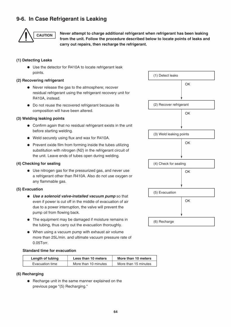
Length of tubing
Evacuation time
Less than 10 meters
More than 10 minutes
More than 10 meters
More than 15 minutes
9-6. In Case Refrigerant is Leaking
CAUTION Never attempt to charge additional refrigerant when refrigerant has been leaking from the unit. Follow the procedure described below to locate points of leaks and carry out repairs, then recharge the refrigerant.
(1) Detecting Leaks
Use the detector for R410A to locate refrigerant leak points.
(2) Recovering refrigerant
Never release the gas to the atmosphere; recover residual refrigerant using the refrigerant recovery unit for R410A, instead.
Do not reuse the recovered refrigerant because its composition will have been altered.
(3) Welding leaking points
Confirm again that no residual refrigerant exists in the unit before starting welding.
Weld securely using flux and wax for R410A.
Prevent oxide film from forming inside the tubes utilizing substitution with nitrogen (N2) in the refrigerant circuit of the unit. Leave ends of tubes open during welding.
(4) Checking for sealing
Use nitrogen gas for the pressurized gas, and never use a refrigerant other than R410A. Also do not use oxygen or any flammable gas.
(5) Evacuation
Use a solenoid valve-installed vacuum pump so that even if power is cut off in the middle of evacuation of air due to a power interruption, the valve will prevent the pump oil from flowing back.
The equipment may be damaged if moisture remains in the tubing, thus carry out the evacuation thoroughly.
When using a vacuum pump with exhaust air volume more than 25L/min. and ultimate vacuum pressure rate of 0.05Torr.
Standard time for evacuation
(6) Recharging
Recharge unit in the same manner explained on the previous page "(5) Recharging."
(2) Recover refrigerant
OK
(3) Weld leaking points
OK
(4) Check for sealing
OK
(5) Evacuation
OK
(6) Recharge
(1) Detect leaks
OK
64

9-7. Charging Additional Refrigerant
9-7-1. When Tubes are Extended
Observe the proper amount of refrigerant as stated in this service manual or the installation manual that came with the indoor unit. Charge additional refrigerant in liquid state only.
9-8. Retro-Fitting Existing Systems
9-8-1. Use of Existing Units
Never use new refrigerant R410A for existing units which use R22. This will cause the air conditioner to operate improperly and may result in a hazardous condition.
9-8-2. Use of Existing Tubing
If replacing an older unit that used refrigerant R22 with a R410A unit, do not use its existing tubing. Instead, completely new tubing must be used.
CAUTION Never charge additional refrigerant if refrigerant is leaking from the unit. Follow instructions given in "9-6. In Case Refrigerant is Leaking" and completely carry out repairs. Only then should you recharge the refrigerant.
65

UNIT COMBINATION TABLESAPPENDIX
Be sure to operate the air conditioning system only when 2 or more indoor units have been installed. If operated with only a single unit installed, the returning fluid to the compressor may cause a malfunction.
NOTE
< List of Combination Table >
Name of Combination Table
2-Room Outdoor Unit Combination Table
2-Room Outdoor Unit Combination Table
4-Room Outdoor Unit Combination Table
4-Room Outdoor Unit Combination Table
Model No. of Outdoor Unit
GRF148MR5I
GRF198MR5I
GRF248MR5I
GRF318MR5I
Remarks
OI-852-6-4181-053-00-0
OI-852-6-4181-054-00-0
OI-852-6-4181-055-00-0
OI-852-6-4181-056-00-0
A-1

Pub. OI-85264181053000
R.D. 28 Reyrieux BP 131-01601 Trévoux CEDEX FranceTel. (33) 04.74.00.92.92 - Fax (33) 04.74.00.42.00
http://www.technibel.com
GRF148MR5I• Refer to the catalog for the combination indoor units.• Store this table together with the operation manual supplied with the indoor unit.
<Combinations of Connectable Indoor Units>The combinations of the indoor units listed in Table 1 on the next page are combinations solely of those units which can be operated concurrently. In addition to the combinations listed in the table, other combinations of indoor units are possible provided that the following conditions are satisfied.
Conditions:1. At least two or more indoor units must be connected to the multi outdoor unit. It is not acceptable for only one indoor
unit to be connected.2. The total rated cooling capacity of the indoor units to be connected must be no more than 200% of the rated cooling
capacity of the outdoor unit.
Example: When two indoor units are connected
If the following holds true• Rated cooling capacity of GRF148MR5I outdoor unit: C=4 (kW)• Rated cooling capacity of indoor units: K1, K2, ... (kW)
Then:
It is therefore possible to connect two units with respective capacities of 3.5 + 3.5. However, since this combination is not found in the 2-room operation column of Table 1, operating all these units concurrently may result in trouble. At a time like this, shut down at least one of the two indoor units to match one of the combinations found in the single-room operation col-umn of Table 1.
2-Room Outdoor Unit Combination Table
In this case, all the indoor units installed must not be operated concurrently under any circumstances. Otherwise, the air conditioner may not run properly and trouble may occur.
Be sure to operate the air conditioning system only when 2 or more indoor units have been installed. If operated with only a single unit installed, the returning fluid to the compressor may cause a malfunction.
CAUTION
C x 2 (200%) K1 + K2 + .......4 x 2 3.5 + 3.58 7
NOTE

Table 1
Room Room Room RoomA B Capacity ( Min. - Max. ) A B Capacity ( Min. - Max. )
2.2 = 2.2 2.2 2.2 ( 1.2 - 2.6 ) 2.5 2.5 ( 1.4 - 3.5 )2.65 = 2.65 2.65 2.65 ( 1.2 - 3.2 ) 3.6 3.6 ( 1.4 - 4.0 )3.5 = 3.5 3.5 3.5 ( 1.3 - 3.6 ) 4.2 4.2 ( 1.5 - 4.2 )2.2 + 2.2 = 4.4 1.8 1.8 3.6 ( 2.0 - 4.5 ) 2.1 2.1 4.2 ( 2.0 - 5.0 )2.2 + 2.65 = 4.85 1.68 2.02 3.7 ( 2.0 - 4.8 ) 1.72 2.48 4.2 ( 2.0 - 5.0 )2.2 + 3.5 = 5.7 1.51 2.39 3.9 ( 2.0 - 4.9 ) 1.64 2.76 4.4 ( 2.2 - 5.3 )
2.65 + 2.65 = 5.3 2 2 4.0 ( 2.0 - 5.0 ) 2.25 2.25 4.5 ( 2.2 - 5.5 )2.65 + 3.5 = 6.15 1.72 2.28 4.0 ( 2.1 - 5.0 ) 2.08 2.42 4.5 ( 2.4 - 5.5 )
Indoor Unit Capacity (kW)HEATING COOLING
< Combinations of operatable indoor units >
GRF148MR5I(Rated cooling capacity: 4.0 kW)
2-roomOperation
Total Performance Total Performance
Single-roomOperation
Indoor Unit Combination
2.2: MCAF78MR5I 2.65: MCAF98MR5I
3.5: MCAF128MR5I
NOTE

Pub. OI-85264181054000
R.D. 28 Reyrieux BP 131-01601 Trévoux CEDEX FranceTel. (33) 04.74.00.92.92 - Fax (33) 04.74.00.42.00
http://www.technibel.com
GRF198MR5I• Refer to the catalog for the combination indoor units.• Store this table together with the operation manual supplied with the indoor unit.
<Combinations of Connectable Indoor Units>The combinations of the indoor units listed in Table 1 on the next page are combinations solely of those units which can be operated concurrently. In addition to the combinations listed in the table, other combinations of indoor units are possible provided that the following conditions are satisfied.
Conditions:1. At least two or more indoor units must be connected to the multi outdoor unit. It is not acceptable for only one indoor
unit to be connected.2. The total rated cooling capacity of the indoor units to be connected must be no more than 200% of the rated cooling
capacity of the outdoor unit.
Example: When two indoor units are connected
If the following holds true• Rated cooling capacity of GRF198MR5I outdoor unit: C=5.6 (kW)• Rated cooling capacity of indoor units: K1, K2, ... (kW)
Then:
It is therefore possible to connect two units with respective capacities of 5.15 + 5.15. However, since this combination is notfound in the 2-room operation column of Table 1, operating all these units concurrently may result in trouble. At a time like this, shut down at least one of the two indoor units to match one of the combinations found in the single-room operation col-umn of Table 1.
2-Room Outdoor Unit Combination Table
In this case, all the indoor units installed must not be operated concurrently under any circumstances. Otherwise, the air conditioner may not run properly and trouble may occur.
Be sure to operate the air conditioning system only when 2 or more indoor units have been installed. If operated with only a single unit installed, the returning fluid to the compressor may cause a malfunction.
CAUTION
C x 2 (200%) K1 + K2 + .......5.6 x 2 5.15 + 5.1511.2 10.3
NOTE

Table 1
Room Room Room RoomA B Capacity ( Min. - Max. ) A B Capacity ( Min. - Max. )
2.2 = 2.2 2.2 2.2 ( 1.4 - 2.6 ) 2.5 2.5 ( 1.8 - 4.3 )2.65 = 2.65 2.65 2.65 ( 1.4 - 3.2 ) 3.6 3.6 ( 1.8 - 4.7 )3.5 = 3.5 3.5 3.5 ( 1.5 - 3.6 ) 4.2 4.2 ( 1.9 - 5.1 )5.15 = 5.15 5.15 5.15 ( 1.6 - 5.8 ) 6.0 6.0 ( 2 - 7.8 )2.2 + 2.2 = 4.4 2.2 2.2 4.4 ( 2.0 - 5.1 ) 2.5 2.5 5.0 ( 2 - 6.4 )2.2 + 2.65 = 4.85 2.2 2.65 4.85 ( 2.0 - 5.8 ) 2.5 3.6 6.1 ( 2.1 - 7.5 )2.2 + 3.5 = 5.7 1.97 3.13 5.1 ( 2.0 - 6.7 ) 2.4 3.9 6.3 ( 2.1 - 8.3 )2.2 + 5.15 = 7.35 1.65 3.85 5.5 ( 2.1 - 6.8 ) 2.03 4.87 6.9 ( 2.4 - 8.4 )2.65 + 2.65 = 5.3 2.50 2.50 5 ( 2.0 - 6.3 ) 3.2 3.2 6.45 ( 2.3 - 8.4 )2.65 + 3.5 = 6.15 2.24 2.96 5.2 ( 2.1 - 6.8 ) 3.07 3.58 6.65 ( 2.3 - 8.4 )2.65 + 5.15 = 7.8 1.9 3.7 5.6 ( 2.1 - 6.8 ) 2.74 4.56 7.3 ( 2.4 - 8.4 )3.5 + 3.5 = 7 2.7 2.7 5.4 ( 2.0 - 6.8 ) 3.45 3.45 6.9 ( 2.3 - 8.4 )3.5 + 5.15 = 8.65 2.27 3.33 5.6 ( 2.1 - 6.8 ) 3.01 4.29 7.3 ( 2.4 - 8.4 )
2-roomOperation
Single-roomOperation
Indoor Unit Combination
< Combinations of operatable indoor units >
GRF198MR5I(Rated cooling capacity: 5.6 kW)
Total Performance Total Performance
Indoor Unit Capacity (kW) COOLING HEATING
2.2: MCAF78MR5I 2.65: MCAF98MR5I
3.5: MCAF128MR5I 5.15: MCAF188R5I
NOTE

Pub. OI-85264181055000
R.D. 28 Reyrieux BP 131-01601 Trévoux CEDEX FranceTel. (33) 04.74.00.92.92 - Fax (33) 04.74.00.42.00
http://www.technibel.com
GRF248MR5I• Refer to the catalog for the combination indoor units.• Store this table together with the operation manual supplied with the indoor unit.
<Combinations of Connectable Indoor Units>The combinations of the indoor units listed in Table 1 on the next page are combinations solely of those units which can be operated concurrently. In addition to the combinations listed in the table, other combinations of indoor units are possible provided that the following conditions are satisfied.
Conditions:1. At least two or more indoor units must be connected to the multi outdoor unit. It is not acceptable for only one indoor
unit to be connected.2. The total rated cooling capacity of the indoor units to be connected must be no more than 200% of the rated cooling
capacity of the outdoor unit.
Example: When four indoor units are connected
If the following holds true• Rated cooling capacity of GRF248MR5I outdoor unit: C=6.8 (kW)• Rated cooling capacity of indoor units: K1, K2, ... (kW)
Then:
It is therefore possible to connect four units with respective capacities of 2.2 + 2.2 + 2.2 + 5.15. However, since this combi-nation is not found in the 4-room operation column of Table 1, operating all these units concurrently may result in trouble. At a time like this, shut down at least one of the four indoor units to match one of the combinations found in the 3-room opera-tion column of Table 1.
4-Room Outdoor Unit Combination Table
In this case, all the indoor units installed must not be operated concurrently under any circumstances. Otherwise, the air conditioner may not run properly and trouble may occur.
Be sure to operate the air conditioning system only when 2 or more indoor units have been installed. If operated with only a single unit installed, the returning fluid to the compressor may cause a malfunction.
CAUTION
C x 2 (200%) K1 + K2 + .......6.8 x 2 2.2 + 2.2 + 2.2 + 5.1513.6 11.75
NOTE

Table 1
Room Room Room Room Room Room Room Room A B C D Capacity ( Min. - Max.) A B C D Capacity ( Min. - Max. )
2.2 = 2.2 2.2 2.2 ( 1.4 - 2.6 ) 2.5 2.5 ( 1.8 - 4.3 )2.65 = 2.65 2.65 2.65 ( 1.4 - 3.2 ) 3.6 3.6 ( 1.8 - 4.7 )
3.5 = 3.5 3.5 3.5 ( 1.5 - 3.6 ) 4.2 4.2 ( 1.9 - 5.1 )5.15 = 5.15 5.15 5.15 ( 1.6 - 5.8 ) 6.0 6.0 ( 2 - 7.8 )
7.1 = 7.1 6.8 6.8 ( 1.6 - 6.8 ) 8.0 8.0 ( 2 - 8.0 )2.2 + 2.2 = 4.4 2.2 2.2 4.4 ( 2.0 - 5.1 ) 2.50 2.50 5.0 ( 2 - 6.4 )2.2 + 2.65 = 4.85 2.2 2.65 4.85 ( 2.0 - 5.8 ) 2.50 3.60 6.1 ( 2.1 - 7.5 )2.2 + 3.5 = 5.7 2.2 3.5 5.7 ( 2.0 - 6.7 ) 2.50 4.20 6.7 ( 2.1 - 8.3 )2.2 + 5.15 = 7.35 1.98 4.62 6.6 ( 2.1 - 7.7 ) 2.44 5.86 8.3 ( 2.4 - 9.0 )2.2 + 7.1 = 9.3 1.61 5.19 6.8 ( 2.1 - 8.1 ) 1.95 6.65 8.6 ( 2.4 - 9.0 )
2.65 + 2.65 = 5.3 2.65 2.65 5.3 ( 2.0 - 6.3 ) 3.60 3.60 7.2 ( 2.3 - 8.5 )2.65 + 3.5 = 6.15 2.54 3.36 5.9 ( 2.0 - 6.8 ) 3.51 4.09 7.6 ( 2.3 - 8.5 )2.65 + 5.15 = 7.8 2.28 4.42 6.7 ( 2.1 - 8.1 ) 3.15 5.25 8.4 ( 2.4 - 9.0 )2.65 + 7.1 = 9.75 1.85 4.95 6.8 ( 2.1 - 8.1 ) 2.56 6.04 8.6 ( 2.4 - 9.0 )
3.5 + 3.5 = 7 3.3 3.3 6.6 ( 2.0 - 8.1 ) 4.00 4.00 8.0 ( 2.3 - 8.5 )3.5 + 5.15 = 8.65 2.75 4.05 6.8 ( 2.1 - 8.1 ) 3.50 5.00 8.5 ( 2.4 - 9.0 )3.5 + 7.1 = 10.6 2.25 4.55 6.8 ( 2.1 - 8.1 ) 2.84 5.76 8.6 ( 2.4 - 9.0 )
5.15 + 5.15 = 10.3 3.4 3.4 6.8 ( 2.1 - 8.1 ) 4.3 4.3 8.6 ( 2.4 - 9.0 )2.2 + 2.2 + 2.2 = 6.6 2.2 2.2 2.2 6.5 ( 2.5 - 7.7 ) 2.5 2.5 2.5 7.5 ( 2.7 - 8.5 )2.2 + 2.2 + 2.65 = 7.05 2.06 2.06 2.48 6.6 ( 2.9 - 8.1 ) 2.3 2.3 3.3 8 ( 3 - 9.0 )2.2 + 2.2 + 3.5 = 7.9 1.88 1.88 2.99 6.75 ( 2.9 - 8.1 ) 2.26 2.26 3.79 8.3 ( 3.2 - 9.0 )2.2 + 2.2 + 5.15 = 9.55 1.57 1.57 3.67 6.8 ( 2.9 - 8.1 ) 1.95 1.95 4.69 8.6 ( 3.4 - 9.0 )2.2 + 2.65 + 2.65 = 7.5 1.97 2.4 2.4 6.7 ( 2.9 - 8.1 ) 2.16 3.12 3.12 8.4 ( 3.4 - 9.0 )2.2 + 2.65 + 3.5 = 8.35 1.79 2.16 2.85 6.8 ( 2.9 - 8.1 ) 2.06 2.97 3.47 8.5 ( 3.4 - 9.0 )2.2 + 2.65 + 5.15 = 10 1.5 1.8 3.5 6.8 ( 2.9 - 8.1 ) 1.78 2.56 4.26 8.6 ( 3.4 - 9.0 )2.2 + 3.5 + 3.5 = 9.2 1.63 2.59 2.59 6.8 ( 2.9 - 8.1 ) 1.97 3.31 3.31 8.6 ( 3.4 - 9.0 )2.2 + 3.5 + 5.15 = 10.9 1.38 2.19 3.23 6.8 ( 2.9 - 8.1 ) 1.69 2.84 4.06 8.6 ( 3.4 - 9.0 )
2.65 + 2.65 + 2.65 = 7.95 2.27 2.27 2.27 6.8 ( 2.9 - 8.1 ) 2.87 2.87 2.87 8.6 ( 3.4 - 9.0 )2.65 + 2.65 + 3.5 = 8.8 2.05 2.05 2.7 6.8 ( 2.9 - 8.1 ) 2.72 2.72 3.17 8.6 ( 3.4 - 9.0 )2.65 + 2.65 + 5.15 = 10.5 1.72 1.72 3.35 6.8 ( 2.9 - 8.1 ) 2.35 2.35 3.91 8.6 ( 3.4 - 9.0 )2.65 + 3.5 + 3.5 = 9.65 1.87 2.47 2.47 6.8 ( 2.9 - 8.1 ) 2.58 3.01 3.01 8.6 ( 3.4 - 9.0 )2.65 + 3.5 + 5.15 = 11.3 1.59 2.11 3.1 6.8 ( 2.9 - 8.1 ) 2.24 2.62 3.74 8.6 ( 3.4 - 9.0 )
3.5 + 3.5 + 3.5 = 10.5 2.27 2.27 2.27 6.8 ( 2.9 - 8.1 ) 2.87 2.87 2.87 8.6 ( 3.4 - 9.0 )3.5 + 3.5 + 5.15 = 12.2 1.96 1.96 2.88 6.8 ( 2.9 - 8.1 ) 2.51 2.51 3.58 8.6 ( 3.4 - 9.0 )
< Combinations of operatable indoor units >
GRF248MR5I(Rated cooling capacity: 6.8 kW)
Indoor Unit Capacity (kW) COOLING HEATING
Total PerformanceIndoor Unit Combination
Single-roomOperation
4-roomOperation
2-roomOperation
3-roomOperation
Total Performance
2.2: MCAF78MR5I 2.65: MCAF98MR5I3.5: MCAF128MR5I
5.15: MCAF188R5I 7.1: MCAF248R5I
NOTE
IMPORTANT (Concurrent operation of 4 indoor units prohibited)This multi outdoor unit allows up to four indoor units to be connected. However, all four indoor units must not be operated concurrently. Otherwise, the air conditioner may not run properly.Up to three indoor units may be operated concurrently.

Pub. OI-85264181056000
R.D. 28 Reyrieux BP 131-01601 Trévoux CEDEX FranceTel. (33) 04.74.00.92.92 - Fax (33) 04.74.00.42.00
http://www.technibel.com
GRF318MR5I• Refer to the catalog for the combination indoor units.• Store this table together with the operation manual supplied with the indoor unit.
<Combinations of Connectable Indoor Units>The combinations of the indoor units listed in Table 1 on the next page are combinations solely of those units which can be operated concurrently. In addition to the combinations listed in the table, other combinations of indoor units are possible provided that the following conditions are satisfied.
Conditions:1. At least two or more indoor units must be connected to the multi outdoor unit. It is not acceptable for only one indoor
unit to be connected.2. The total rated cooling capacity of the indoor units to be connected must be no more than 200% of the rated cooling
capacity of the outdoor unit.
Example: When four indoor units are connected
If the following holds true• Rated cooling capacity of GRF318MR5I outdoor unit: C=8 (kW)• Rated cooling capacity of indoor units: K1, K2, ... (kW)
Then:
It is therefore possible to connect four units with respective capacities of 2.2 + 2.2 + 3.5 + 7.1. However, since this combina-tion is not found in the 4-room operation column of Table 1, operating all these units concurrently may result in trouble. At a time like this, shut down at least one of the four indoor units to match one of the combinations found in the 3-room opera-tion column of Table 1.
4-Room Outdoor Unit Combination Table
In this case, all the indoor units installed must not be operated concurrently under any circumstances. Otherwise, the air conditioner may not run properly and trouble may occur.
Be sure to operate the air conditioning system only when 2 or more indoor units have been installed. If operated with only a single unit installed, the returning fluid to the compressor may cause a malfunction.
CAUTION
C x 2 (200%) K1 + K2 + .......8 x 2 2.2 + 2.2 + 3.5 + 7.116 15
NOTE

Table 1
Room Room Room Room Room Room Room RoomA B C D Capacity ( Min. - Max. ) A B C D Capacity ( Min. - Max. )
2.2 = 2.2 2.2 2.2 ( 1.5 - 2.6 ) 2.5 2.5 ( 1.8 - 4.3 )2.65 = 2.65 2.65 2.65 ( 1.5 - 3.2 ) 3.6 3.6 ( 1.8 - 4.7 )3.5 = 3.5 3.5 3.5 ( 1.6 - 3.6 ) 4.2 4.2 ( 1.9 - 5.1 )
5.15 = 5.15 5.15 5.15 ( 1.7 - 5.8 ) 6 6 ( 2.0 - 7.8 )7.1 = 7.1 7.1 7.1 ( 1.8 - 7.4 ) 8.5 8.5 ( 2.0 - 8.8 )2.2 + 2.2 = 4.4 2.2 2.2 4.4 ( 2.0 - 5.1 ) 2.5 2.5 5 ( 2.0 - 6.4 )2.2 + 2.65 = 4.85 2.2 2.65 4.85 ( 2.0 - 5.8 ) 2.5 3.6 6.1 ( 2.1 - 7.5 )2.2 + 3.5 = 5.7 2.2 3.5 5.7 ( 2.0 - 6.7 ) 2.5 4.2 6.7 ( 2.3 - 8.3 )2.2 + 5.15 = 7.35 2.14 5.01 7.15 ( 2.2 - 7.7 ) 2.5 6 8.5 ( 3.0 - 9.4 )2.2 + 7.1 = 9.3 1.81 5.84 7.65 ( 2.3 - 8.8 ) 2.01 6.84 8.85 ( 3.0 - 9.8 )
2.65 + 2.65 = 5.3 2.65 2.65 5.3 ( 2.0 - 6.5 ) 3.6 3.6 7.2 ( 2.4 - 8.5 )2.65 + 3.5 = 6.15 2.54 3.36 5.9 ( 2.0 - 7.4 ) 3.51 4.09 7.6 ( 2.6 - 8.5 )2.65 + 5.15 = 7.8 2.46 4.79 7.25 ( 2.3 - 8.5 ) 3.24 5.41 8.65 ( 3.3 - 9.4 )2.65 + 7.1 = 9.75 2.11 5.64 7.75 ( 2.3 - 8.8 ) 2.68 6.32 9 ( 3.3 - 9.8 )3.5 + 3.5 = 7 3.4 3.4 6.8 ( 2.2 - 8.4 ) 4 4 8 ( 2.9 - 8.5 )3.5 + 5.15 = 8.65 3.03 4.47 7.5 ( 2.6 - 8.8 ) 3.6 5.15 8.75 ( 3.4 - 9.8 )3.5 + 7.1 = 10.6 2.63 5.33 7.95 ( 2.6 - 8.8 ) 3.02 6.12 9.14 ( 3.4 - 9.8 )
5.15 + 5.15 = 10.3 3.95 3.95 7.9 ( 2.6 - 8.8 ) 4.5 4.5 9 ( 3.4 - 9.8 )5.15 + 7.1 = 12.3 3.36 4.64 8 ( 2.7 - 8.8 ) 3.89 5.51 9.4 ( 3.4 - 9.8 )2.2 + 2.2 + 2.2 = 6.6 2.2 2.2 2.2 6.6 ( 2.0 - 7.7 ) 2.5 2.5 2.5 7.5 ( 2.7 - 9.0 )2.2 + 2.2 + 2.65 = 7.05 2.2 2.2 2.65 7.05 ( 2.2 - 8.4 ) 2.47 2.47 3.56 8.5 ( 3.0 - 9.2 )2.2 + 2.2 + 3.5 = 7.9 2.03 2.03 3.23 7.3 ( 2.4 - 8.6 ) 2.34 2.34 3.93 8.6 ( 3.2 - 9.8 )2.2 + 2.2 + 5.15 = 9.55 1.77 1.77 4.15 7.7 ( 2.7 - 9.0 ) 2.01 2.01 4.83 8.85 ( 3.4 - 9.8 )2.2 + 2.2 + 7.1 = 11.5 1.53 1.53 4.94 8 ( 2.9 - 9.0 ) 1.71 1.71 5.82 9.25 ( 3.4 - 9.8 )2.2 + 2.65 + 2.65 = 7.5 2.11 2.54 2.54 7.2 ( 2.3 - 8.6 ) 2.23 3.21 3.21 8.65 ( 3.3 - 9.3 )2.2 + 2.65 + 3.5 = 8.35 1.95 2.35 3.1 7.4 ( 2.6 - 9.0 ) 2.12 3.06 3.57 8.75 ( 3.4 - 9.8 )2.2 + 2.65 + 5.15 = 10 1.72 2.07 4.02 7.8 ( 2.9 - 9.0 ) 1.86 2.68 4.46 9 ( 3.4 - 9.8 )2.2 + 2.65 + 7.1 = 12 1.47 1.77 4.75 8 ( 2.9 - 9.0 ) 1.61 2.32 5.47 9.4 ( 3.4 - 9.8 )2.2 + 3.5 + 3.5 = 9.2 1.82 2.89 2.89 7.6 ( 2.7 - 9.0 ) 2.03 3.41 3.41 8.85 ( 3.4 - 9.8 )2.2 + 3.5 + 5.15 = 10.9 1.6 2.55 3.75 7.9 ( 2.9 - 9.0 ) 1.79 3.01 4.3 9.1 ( 3.4 - 9.8 )2.2 + 3.5 + 7.1 = 12.8 1.38 2.19 4.44 8 ( 2.9 - 9.0 ) 1.55 2.6 5.26 9.4 ( 3.4 - 9.8 )2.2 + 5.15 + 5.15 = 12.5 1.41 3.3 3.3 8 ( 2.9 - 9.0 ) 1.62 3.89 3.89 9.4 ( 3.4 - 9.8 )2.2 + 5.15 + 7.1 = 14.5 1.22 2.85 3.93 8 ( 2.9 - 9.0 ) 1.38 3.32 4.7 9.4 ( 3.4 - 9.8 )
2.65 + 2.65 + 2.65 = 7.95 2.43 2.43 2.43 7.3 ( 2.5 - 8.6 ) 2.95 2.95 2.95 8.85 ( 3.4 - 9.4 )2.65 + 2.65 + 3.5 = 8.8 2.26 2.26 2.98 7.5 ( 2.7 - 9.0 ) 2.81 2.81 3.28 8.9 ( 3.4 - 9.8 )2.65 + 2.65 + 5.15 = 10.5 2.0 2.0 3.89 7.9 ( 2.9 - 9.0 ) 2.51 2.51 4.18 9.2 ( 3.4 - 9.8 )2.65 + 2.65 + 7.1 = 12.4 1.71 1.71 4.58 8 ( 2.9 - 9.0 ) 2.16 2.16 5.09 9.4 ( 3.4 - 9.8 )2.65 + 3.5 + 3.5 = 9.65 2.13 2.81 2.81 7.75 ( 2.7 - 9.0 ) 2.7 3.15 3.15 9 ( 3.4 - 9.8 )2.65 + 3.5 + 5.15 = 11.3 1.88 2.48 3.65 8 ( 2.9 - 9.0 ) 2.43 2.83 4.04 9.3 ( 3.4 - 9.8 )2.65 + 3.5 + 7.1 = 13.3 1.6 2.11 4.29 8 ( 2.9 - 9.0 ) 2.08 2.42 4.9 9.4 ( 3.4 - 9.8 )2.65 + 5.15 + 5.15 = 13 1.64 3.18 3.18 8 ( 2.9 - 9.0 ) 2.17 3.62 3.62 9.4 ( 3.4 - 9.8 )3.5 + 3.5 + 3.5 = 10.5 2.65 2.65 2.65 7.95 ( 2.9 - 9.0 ) 3.03 3.03 3.03 9.1 ( 3.4 - 9.8 )3.5 + 3.5 + 5.15 = 12.2 2.3 2.3 3.39 8 ( 2.9 - 9.0 ) 2.73 2.73 3.9 9.35 ( 3.4 - 9.8 )3.5 + 3.5 + 7.1 = 14.1 1.99 1.99 4.03 8 ( 2.9 - 9.0 ) 2.34 2.34 4.73 9.4 ( 3.4 - 9.8 )3.5 + 5.15 + 5.15 = 13.8 2.03 2.99 2.99 8 ( 2.9 - 9.0 ) 2.44 3.48 3.48 9.4 ( 3.4 - 9.8 )2.2 + 2.2 + 2.2 + 2.2 = 8.8 1.88 1.88 1.88 1.88 7.5 ( 2.9 - 9.2 ) 2.18 2.18 2.18 2.18 8.7 ( 3.4 - 9.8 )2.2 + 2.2 + 2.2 + 2.65 = 9.25 1.82 1.82 1.82 2.19 7.65 ( 2.9 - 9.2 ) 1.99 1.99 1.99 2.87 8.85 ( 3.4 - 9.8 )2.2 + 2.2 + 2.2 + 3.5 = 10.1 1.71 1.71 1.71 2.72 7.85 ( 2.9 - 9.2 ) 1.91 1.91 1.91 3.21 8.95 ( 3.4 - 9.8 )2.2 + 2.2 + 2.2 + 5.15 = 11.8 1.5 1.5 1.5 3.51 8 ( 2.9 - 9.2 ) 1.71 1.71 1.71 4.11 9.25 ( 3.4 - 9.8 )2.2 + 2.2 + 2.2 + 7.1 = 13.7 1.28 1.28 1.28 4.15 8 ( 2.9 - 9.2 ) 1.47 1.47 1.47 4.99 9.4 ( 3.4 - 9.8 )2.2 + 2.2 + 2.65 + 2.65 = 9.7 1.76 1.76 2.12 2.12 7.75 ( 2.9 - 9.2 ) 1.85 1.85 2.67 2.67 9.05 ( 3.4 - 9.8 )2.2 + 2.2 + 2.65 + 3.5 = 10.6 1.66 1.66 2 2.64 7.95 ( 2.9 - 9.2 ) 1.79 1.79 2.57 3 9.15 ( 3.4 - 9.8 )2.2 + 2.2 + 2.65 + 5.15 = 12.2 1.44 1.44 1.74 3.38 8 ( 2.9 - 9.2 ) 1.61 1.61 2.32 3.86 9.4 ( 3.4 - 9.8 )2.2 + 2.2 + 2.65 + 7.1 = 14.2 1.24 1.24 1.5 4.01 8 ( 2.9 - 9.2 ) 1.37 1.37 1.98 4.67 9.4 ( 3.4 - 9.8 )2.2 + 2.2 + 3.5 + 3.5 = 11.4 1.54 1.54 2.46 2.46 8 ( 2.9 - 9.2 ) 1.72 1.72 2.88 2.88 9.2 ( 3.4 - 9.8 )2.2 + 2.2 + 3.5 + 5.15 = 13.1 1.35 1.35 2.15 3.16 8 ( 2.9 - 9.2 ) 1.55 1.55 2.6 3.71 9.4 ( 3.4 - 9.8 )2.2 + 2.2 + 5.15 + 5.15 = 14.7 1.2 1.2 2.8 2.8 8 ( 2.9 - 9.2 ) 1.38 1.38 3.32 3.32 9.4 ( 3.4 - 9.8 )2.2 + 2.65 + 2.65 + 2.65 = 10.2 1.7 2.05 2.05 2.05 7.85 ( 2.9 - 9.2 ) 1.73 2.49 2.49 2.49 9.2 ( 3.4 - 9.8 )2.2 + 2.65 + 2.65 + 3.5 = 11 1.6 1.93 1.93 2.55 8 ( 2.9 - 9.2 ) 1.67 2.41 2.41 2.81 9.3 ( 3.4 - 9.8 )2.2 + 2.65 + 2.65 + 5.15 = 12.7 1.39 1.68 1.68 3.26 8 ( 2.9 - 9.2 ) 1.5 2.16 2.16 3.59 9.4 ( 3.4 - 9.8 )2.2 + 2.65 + 3.5 + 3.5 = 11.9 1.49 1.79 2.36 2.36 8 ( 2.9 - 9.2 ) 1.62 2.33 2.72 2.72 9.4 ( 3.4 - 9.8 )2.2 + 2.65 + 3.5 + 5.15 = 13.5 1.3 1.57 2.07 3.05 8 ( 2.9 - 9.2 ) 1.44 2.08 2.42 3.46 9.4 ( 3.4 - 9.8 )2.2 + 3.5 + 3.5 + 3.5 = 12.7 1.39 2.2 2.2 2.2 8 ( 2.9 - 9.2 ) 1.56 2.61 2.61 2.61 9.4 ( 3.4 - 9.8 )2.2 + 3.5 + 3.5 + 5.15 = 14.4 1.23 1.95 1.95 2.87 8 ( 2.9 - 9.2 ) 1.39 2.34 2.34 3.34 9.4 ( 3.4 - 9.8 )
2.65 + 2.65 + 2.65 + 2.65 = 10.6 2 2 2 2 8 ( 2.9 - 9.2 ) 2.35 2.35 2.35 2.35 9.4 ( 3.4 - 9.8 )2.65 + 2.65 + 2.65 + 3.5 = 11.5 1.85 1.85 1.85 2.45 8 ( 2.9 - 9.2 ) 2.26 2.26 2.26 2.63 9.4 ( 3.4 - 9.8 )2.65 + 2.65 + 2.65 + 5.15 = 13.1 1.62 1.62 1.62 3.15 8 ( 2.9 - 9.2 ) 2.01 2.01 2.01 3.36 9.4 ( 3.4 - 9.8 )2.65 + 2.65 + 3.5 + 3.5 = 12.3 1.72 1.72 2.28 2.28 8 ( 2.9 - 9.2 ) 2.17 2.17 2.53 2.53 9.4 ( 3.4 - 9.8 )2.65 + 2.65 + 3.5 + 5.15 = 14 1.52 1.52 2.01 2.95 8 ( 2.9 - 9.2 ) 1.94 1.94 2.27 3.24 9.4 ( 3.4 - 9.8 )2.65 + 3.5 + 3.5 + 3.5 = 13.2 1.61 2.13 2.13 2.13 8 ( 2.9 - 9.2 ) 2.09 2.44 2.44 2.44 9.4 ( 3.4 - 9.8 )3.5 + 3.5 + 3.5 + 3.5 = 14 2 2 2 2 8 ( 2.9 - 9.2 ) 2.35 2.35 2.35 2.35 9.4 ( 3.4 - 9.8 )
< Combinations of operatable indoor units >
GRF318MR5I(Rated cooling capacity: 8.0 kW)
Total Performance
Indoor Unit Capacity (kW)
Indoor Unit CombinationHEATING COOLING
Total Performance
4-roomOperation
3-roomOperation
2-roomOperation
Single-roomOperation
2.2: MCAF78MR5I 2.65: MCAF98MR5I
3.5: MCAF128MR5I 5.15: MCAF188R5I 7.1: MCAF248R5I
NOTE

R.D. 28 Reyrieux BP 131 - 01601 Trevoux CEDEX France
Tel. (33) 04.74.00.92.92 - Fax (33) 04.74.00.42.00
http://www.technibel.com