Embed Size (px)
Citation preview

T H E L O O K A N D F E E L O F N A T U R E
OUTCROPPING COLLECTION
INSTALLATION GUIDE
Rosetta Outcropping Collection Installation Manual May 20102
Welcome

Rosetta Outcropping Collection Installation ManualMay 2010 3
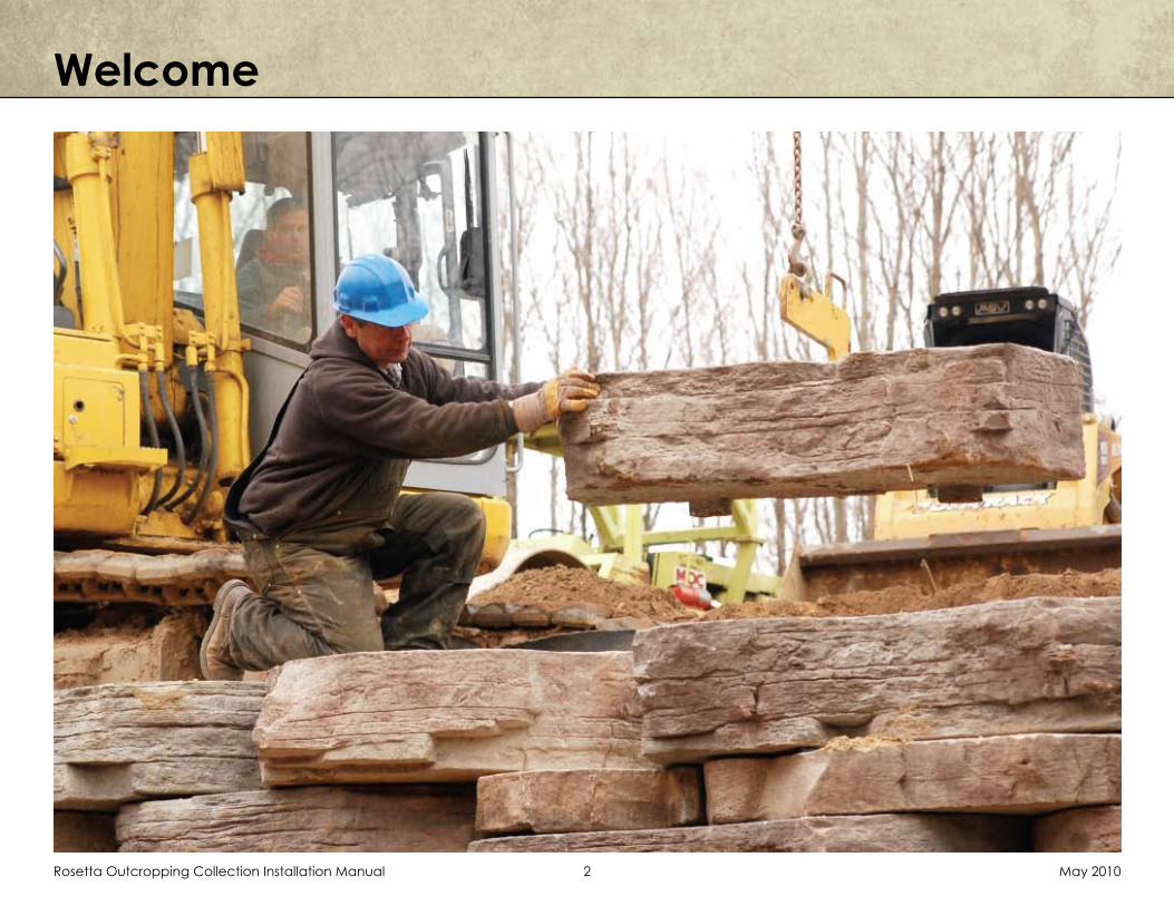
Thank you for your interest in instal-
ling Rosetta’s premium line of hard-
scape products. You will find that
no other engineered system offers
the natural beauty, the design flex-
ibility, and the structural stability of
the Rosetta system. This installation
brochure will give you the fundamen-
tal knowledge needed to construct
stunning, quality retaining walls and
landscape step systems that will last
for generations to come.
www.discoverrosetta.com

Rosetta Outcropping Collection Installation Manual May 20104
Before you start construction, take the time to complete the necessary planning and prepa-ration. This process will keep your project running efficiently and will aid in completing a quality instal-lation. Make sure to address the following:
Develop a project safety plan. Be sure to follow all applicable gov-ernmental (ie. OSHA) standards. Be sure to address items such as: personal protective equipment, maintaining safe slopes, fall pro-tection, rigging and lifting, and any other safety precautions.
Attain the necessary permits and engineering.
Note: This guide is intended to supplement a detailed, site-spe-cific wall design prepared for your project by a Professional Engineer. The actual design for your project supersedes any rec-ommendations presented here.
Review the project plans. Make sure that the plans take into ac-count current site and soil condi-tions. Clays or poor soils place sig-nificantly greater loads on walls than free draining aggregates. If poor soils are present, make sure the plans account for them.
Develop a plan to control surface water during construction.
Pre-Construction

Rosetta Outcropping Collection Installation ManualMay 2010 5
Step 1. Base PreparationProper base preparation is one of the most critical elements of retaining wall construction. The retaining wall is only as stable as the foundation it is placed on. If sub-base soils are deemed unstable, contact a qualified geotechnical engi-neer for remediation.
First, excavate for the leveling pad. The minimum leveling pad thickness is 6”. Higher walls may require a thicker leveling pad based on the detailed wall design. The leveling pad should be a minimum of 40” wide, or wider if called for in the en-gineered construction drawings. The sub grade material needs to be compacted to 95% of standard proctor maximum dry density.
Place 4” perforated sock drain at the back of the excavated trench. Make sure drain has a long term gravity outlet (either to daylight or to approved catch basin).
Place clean crushed stone into excavat-ed trench. Level and compact stone to the design thickness. Check level with a laser or transit. Note: Take time to make sure the base is accurately leveled. This will allow the wall to be installed much more efficiently.

Rosetta Outcropping Collection Installation Manual May 20106
Proper placement of the bottom course of wall stones is critical in determining the overall appearance and integrity of the finished project. Take extra time on this step and the rest of the project will go smoothly. At this point you need to determine the best point of origin for the wall. If you have a fixed point, such as a building corner or a 90° corner, you will want to start the wall from that point and work your way out. This will minimize cutting of blocks. If there are no fixed points, start the wall at the lowest design elevation, as it is easier to step the base up than it is to step the base down. Nearly all segmental block wall systems have a built in batter to provide greater wall stability. With Rosetta, the batter is 14 degrees, which equals 3” of setback for every vertical foot up. One of the unique features of the Rosetta system is multiple block heights. To provide a uniform wall batter with multiple height blocks, the setback of the blocks varies proportionally with the block height. The setback in blocks is acheived with shear heels which are cast into the Rosetta blocks. For a 6” high block, the shear heels are 1.5” deep (1/2 times 3”). For a 12” high block, the shear heels are 3” deep (1 times 3”). For a 24” high block, the shear heels are 6” deep (2 times 3”). To ensure proper wall alignment and to account for the multiple height blocks and vary-ing setbacks, you have to adjust the bottom row of blocks based on their height. Setup a traditional string line for the back of the wall, then offset the blocks per Figure 1.
Step 2. Place Bottom Course
You may find it useful to remove the shear heels from the blocks to be placed on the bottom course. This can be done using a demolition bar. (see Figure 3.) Be sure to do this in a safe manner, keeping your body away from potential falling hazards.
Using an appropriately rated skid steer or small excavator and the Rosetta Lifting Device, place each block along the string line according to Figure 1. Be sure that the safety latch on the Lifting Device is engaged before lifting each block. Use a bar to make small adjustments to bring the blocks into line.
Please note that the Rosetta blocks have an irregular taper on the sides. When placing the bottom course of blocks (as shown on Figure 1), make sure the back corners of the blocks line up with each other perpendicular to the string line.
After placing each block, check for level both front to back and side to side. If the block is out of level, either pick up the block and correct the base material, or tap it into place using the setting machine and a block of wood (to avoid marring the wall stone).
Continue following the above procedures until the entire course of wall stones has been placed.
Figure 2.
Figure 3.
Rosetta Outcropping Collection Installation ManualMay 2010 7
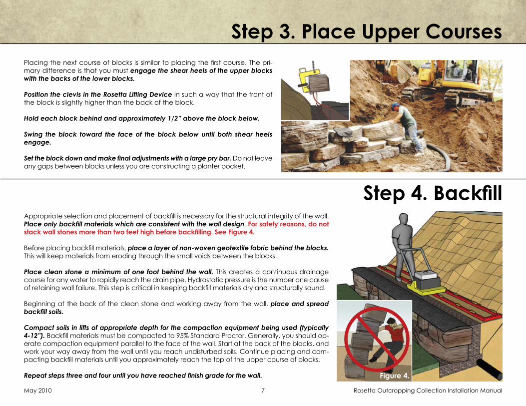
Step 3. Place Upper CoursesPlacing the next course of blocks is similar to placing the first course. The pri-mary difference is that you must engage the shear heels of the upper blocks with the backs of the lower blocks.
Position the clevis in the Rosetta Lifting Device in such a way that the front of the block is slightly higher than the back of the block.
Hold each block behind and approximately 1/2” above the block below.
Swing the block toward the face of the block below until both shear heels engage.
Set the block down and make final adjustments with a large pry bar. Do not leave any gaps between blocks unless you are constructing a planter pocket.
Step 4. BackfillAppropriate selection and placement of backfill is necessary for the structural integrity of the wall. Place only backfill materials which are consistent with the wall design. For safety reasons, do not stack wall stones more than two feet high before backfilling. See Figure 4.
Before placing backfill materials, place a layer of non-woven geotextile fabric behind the blocks. This will keep materials from eroding through the small voids between the blocks.
Place clean stone a minimum of one foot behind the wall. This creates a continuous drainage course for any water to rapidly reach the drain pipe. Hydrostatic pressure is the number one cause of retaining wall failure. This step is critical in keeping backfill materials dry and structurally sound.
Beginning at the back of the clean stone and working away from the wall, place and spread backfill soils.
Compact soils in lifts of appropriate depth for the compaction equipment being used (typically 4-12”). Backfill materials must be compacted to 95% Standard Proctor. Generally, you should op-erate compaction equipment parallel to the face of the wall. Start at the back of the blocks, and work your way away from the wall until you reach undisturbed soils. Continue placing and com-pacting backfill materials until you approximately reach the top of the upper course of blocks.
Repeat steps three and four until you have reached finish grade for the wall. Figure 4.

Rosetta Outcropping Collection Installation Manual May 20108
Step 5. Finishing The WallCompleting a few simple tasks near the end of the project will ensure that the wall will function properly and look good for years to come.
Make sure that the drain pipe is tied into a catch basin or run to a long term daylight opening. If you are using flexible drainpipe behind the wall, convert it to Schedule 40 PVC or equivalent before outleting from be-hind the wall. This will insure that the pipe is not easily crushed during future construc-tion.
Place non-woven geotextile fabric over the clean stone. You may need to leave the clean stone down 4” to 6” from the top of the wall to allow for landscape or other ma-terials.
Grade the top of the wall in such a way that water runs off away from the wall. Never leave the top of a wall graded where sur-face water will pond behind the wall. If fu-ture grading is to take place by others, you should have a responsible party sign off re-garding this point.
Plant appropriate vegetation on the back of the wall
FINISHING OPTIONS
Use Rosetta steps as top blocks, espescially when the grade falls away at the ends of the wall
Place pavers flush with the back of the Rosetta Blocks
Grade slope to rise above top blocks, giving the look of natural outcropping in the bank.(Design must account for surcharge loading)

Rosetta Outcropping Collection Installation ManualMay 2010 9
Other Applications

Rosetta Outcropping Collection Installation Manual May 201010
Begin the step installation process by measuring the total rise required and calculating the number of steps to be used. Each step has a 5½” or 7” rise, but should be sloped approxi-mately ½” such that the back of the step is higher than the front of the step. This sloping will facilitate surface water drainage. With appropriate sloping, the net rise of each step is 6” or 7½”. Divide the total rise by 6” or 7½” to get the number of steps required.
Next, calculate the tread width. Generally, when the grade allows, a 12” or wider tread is desirable. To calculate the tread width, divide the total allowable horizontal run minus the width of the top step, by the number of steps minus one. The one less will account for the top step.
Consider the following example: Total rise = 42”, Total horizontal run = 108”, Width of top step = 24”, Rise of steps = 5½”, Number of steps = 42” ÷ 6”/Step = 7 StepsTread Depth = (108” – 24”) ÷ (7 -1) = 14” Tread Depth
Step Installation
Excavate and grade the area for first step. Steps should be placed on at least 3” of free draining soil, such as sand or pea-stone. Compact soil to a minimum of 95% Standard Proctor.
Place step with either forks or straps using a small excavator or skid-steer to lift the piece into place. Practice safe handling procedures during this process.
Fill behind each step with free draining soil and compact to 95% standard proctor. Remember to slope fill to allow for proper drainage when next step is placed. Continue placing steps in this manner until finish grade is reached.

Rosetta Outcropping Collection Installation ManualMay 2010 11
18 ft.²4000 lbs.
18 ft.²4000 lbs.
18 ft.²4000 lbs.
Note: Color, texture and shape may vary. Length dimensions are nominal.
Outcropping Pallets
12” x 5’ 6”12” x 5’
Pallet A
Pallet B
Pallet C
12” x 4’12” x 3’ 6”
6” x 2’ 6” x 3’
6” x 4’
12” x 3’
12” x 4’ 6” 12” x 6’
18” x 5’
24” x 4’
6” x 2’
6” x 3’

Rosetta Outcropping Collection Installation Manual May 201012
StepsIrregular Steps Dimensional Steps
*All Dimensions NominalNote: Color, texture and shape may vary.
4’
2’4” 5 1/2” Rise - 415 lbs.7” Rise - 567 lbs.
5 1/2” Rise - 391 lbs.7” Rise - 458 lbs
5 1/2” Rise - 289 lbs.7” Rise - 349 lbs.
5 1/2” Rise - 508 lbs.7” Rise - 600 lbs.
5 1/2” Rise - 390 lbs.7” Rise - 476 lbs.
5 1/2” Rise - 424 lbs.7” Rise - 512 lbs.
4’6”
1’10”
3’6”
1’5”
5’
2’
2’2”
3’6”
2’
4’
A B
C D
E F
Approximately 375 lbs.
Approximately 1250 lbs.
Approximately 500 lbs.
36”
48”
7”
7”
18”
30”
72”
7”
18”

Rosetta Outcropping Collection Installation ManualMay 2010 13
Sample PatternsOne of the great advantages of the Rosetta system is the ability of a designer or a contractor to lay out a wall in advance, saving time and effort during installation. The following patterns can be used to aid in wall lay-out and design. Each pattern is 90 square feet and uses 2 A Pallets, 2 B Pallets, and 1 C Pallet. Rosetta custom layout and design software is also available on our website. Please visit www.discoverrosetta.com to download the program.
Please note that the length dimensions shown for Rosetta blocks are rounded for reference. The actual length of the constructed wall will vary slightly from the pattern dimensions shown.
2’ x 45’
3’ x 30’
4’ x 22.5’ 5’ x 18’

Rosetta Outcropping Collection Installation Manual May 201014
CurvesRosetta Blocks have shear heels which provide a setback from lower blocks in the wall, causing the wall to batter back. This batter is important to the engineering design of the wall, and it must be accounted for during construction of a curved wall section.
If you are constructing an outside (convex) curve, the wall batter will cause the blocks higher in the wall will have a shorter radius around the curve than lower blocks. This will cause the higher blocks to “grow” in the wall layout pattern. (This is similar in concept to the inside lane of a race track be-ing shorter than the outside lane.) The result is a potential overlap between some of the blocks in the wall. The best way to deal with this overlap is to sawcut the end of the smaller block, which allows the blocks to fit tight together and all the shear heels to be properly engaged. This sawcut is typically made on an angle to match the taper on the side of the block you are abuting.
1
1
2
2
3
3
4
4
A A
B B
C C
D D
Trim End of Block To Eliminate Overlap Between Blocks
OUTSIDE (CONVEX) CURVES
INSIDE (CONCAVE) CURVES
Install Blocks Tight Together (Trim Ends of Blocks If Needed To Prevent Gaps Between Blocks)
Place Fabric In Voids Between Blocks And Fill
All Voids With Stone

Rosetta Outcropping Collection Installation ManualMay 2010 15
Curves
1
1
2
2
3
3
4
4
A A
B B
C C
D D
Trim End of Block To Eliminate Overlap Between Blocks
OUTSIDE (CONVEX) CURVES
INSIDE (CONCAVE) CURVES
Install Blocks Tight Together (Trim Ends of Blocks If Needed To Prevent Gaps Between Blocks)
Place Fabric In Voids Between Blocks And Fill
All Voids With Stone
If you are constructing an inside (concave) curve, the wall batter will cause the blocks higher in the wall will have a longer radius around the curve than lower blocks. The important step when constructing an inside curve is to keep all blocks tight together. In most cases, the blocks will touch somewhere along the sides of the blocks, not at the back of the blocks. If needed, you can trim the ends off some blocks to prevent gaps from opening up between blocks. When constructing a curve with a short radius, voids may form at the back of the wall where two blocks meet. If this happens simply fill the void areas with drainstone.
Following these steps, Rosetta walls can be properly constructed while providing the flexibility to construct a wide range of curves.

Rosetta Outcropping Collection Installation Manual May 201016
Rosetta has two corner blocks to help make a 90° corner in the wall. The corner blocks are four-sided, and can be installed with alternating faces exposed to maintain a more random look.
The sizes of the corner blocks have been chosen to account for the wall batter in both directions. Two 6” high corner blocks are typically stacked on top of each other and placed on top of a 12” high corner block. Every 12” the corner blocks are intended to be stepped back 3” in both direc-tions. In a few areas, you may need to trim a small part of the corner blocks near the back of the wall to avoid interference with the shear heels on adjacent blocks. See the sample pattern shown here, which details how to make a 90° corner with (4) A Pallets, (4) B Pallets, (2) C Pallets, (3) 12” high corner blocks, and (4) 6” high corner blocks.
Corners

Rosetta Outcropping Collection Installation ManualMay 2010 17
30” 27”
12”6”
48” 39”
Approximately 1170 lbs. Approximately 480 lbs.
Corners

Rosetta Outcropping Collection Installation Manual May 201018
The Rosetta wall system can be engineered to meet your specific needs. For the most up-to-date design information and preliminary wall height charts visit our web-site and click on the DESIGN/ENGINEERING link. There you will find tools, ranging from testing reports to CAD details, to assist in preparing a detailed, site-specific design for your wall.
Rosetta walls are intended to be designed by a professional engineer and built with appropriate construction oversight, giving you the look of a natural stone wall and the con-fidence of a fully engineered wall system that will stand the test of time.
Engineering & Design
ROSETTA® HARDSCAPES LLC - PRELIMINARY WALL HEIGHT GUIDE
GRAVITY WALL WITH POURED-IN-PLACE CONCRETE BACKFILL
Silty Sand, Clayey Sand with an Internal Angle of Friction (F) = 28°
Wall Loading
Condtion ft (m) ft (m) ft (m) ft (m) ft (m) ft (m)
≤ 5.5 (1.68) See Preliminary Gravity Charts
6.0 (1.83) 0.5 (0.15) 0.5 (0.15) 1.5 (0.46) 1.0 (0.30) 5.5 (1.68)
7.0 (2.13) 0.5 (0.15) 0.5 (0.15) 2.0 (0.61) 2.0 (0.61) 6.5 (1.98)
8.0 (2.44) 0.5 (0.15) 0.5 (0.15) 2.5 (0.76) 3.0 (0.91) 7.5 (2.29)
≤ 4.0 (1.22) See Preliminary Gravity Charts
5.0 (1.52) 0.5 (0.15) 0.5 (0.15) 1.5 (0.46) 1.0 (0.30) 4.5 (1.37)
6.0 (1.83) 0.5 (0.15) 0.5 (0.15) 2.0 (0.61) 2.0 (0.61) 5.5 (1.68)
7.0 (2.13) 0.5 (0.15) 0.5 (0.15) 2.5 (0.76) 3.0 (0.91) 6.5 (1.98)
4.0 (1.22) 0.5 (0.15) 0.5 (0.15) 2.0 (0.61) 1.0 (0.30) 3.5 (1.07)
5.0 (1.52) 0.5 (0.15) 0.5 (0.15) 2.5 (0.76) 2.0 (0.61) 4.5 (1.37)
6.0 (1.83) 0.5 (0.15) 0.5 (0.15) 3.0 (0.91) 3.0 (0.91) 5.5 (1.68)
≤ 4.0 (1.22) See Preliminary Gravity Charts
5.0 (1.52) 0.5 (0.15) 0.5 (0.15) 2.5 (0.76) 1.0 (0.30) 4.5 (1.37)
6.0 (1.83) 0.5 (0.15) 0.5 (0.15) 3.0 (0.91) 2.0 (0.61) 5.5 (1.68)
7.0 (2.13) 0.5 (0.15) 0.5 (0.15) 4.0 (1.22) 3.0 (0.91) 6.5 (1.98)
April 29, 2008
Minimum
Pad Depth
Maximum
Wall HeightConcrete Concrete
BlocksStoneWidth Behind
Height
Minimum
Depth
Exposed
Wall BuryDesign
LevelingHeight Above
φ = 28°
NO BACKSLOPE
100 psf (4.79 kPa) LIVE
LOAD SURCHARGE100 psf
(4.79 kPa)
φ = 28°
NO BACKSLOPE
NO SURCHARGE
φ = 28°
NO BACKSLOPE
250 psf (11.96 kPa) LIVE
LOAD SURCHARGE250 psf
(11.96 kPa)
2.51
φ = 28°
1:2.5 (21.8°) BACKSLOPE
NO SURCHARGE
Min. WallBury Depth
(Varies)
Max. Exposed
Wall Height(Varies)
Min. Leveling
Pad Depth(Varies)
Concrete Height
Above Stone(Varies)
Cast-In-Place
Concrete Backfill
Rebar Tie
DrainConcrete Width
Behind Blocks(Varies)
NOTES: The above chart was prepared by Rosetta® Hardscapes LLC for
estimating and conceptual design purposes only. All information is believed to
be true and accurate, however, Rosetta® Hardscapes LLC assumes no
responsibility for the use of these design charts for actual construction.
Determination of the suitability of each chart is the sole responsibility of the
user. Final designs for construction purposes must be performed by a
registered Professional Engineer using the actual conditions of the
proposed site.
1. Unit weight of 28°, 30°, 34° and 40° soils is assumed to be 120pcf (18.9
kN/m3).2. Minimum factors of safety are 1.5 for sliding, 1.5 for overturning and 2.0 for
bearing capacity.
3. Global stability has not been addressed in these charts.
4. The wall design shall address both internal and external drainage and
shall be evaluated by the Professional Engineer who is responsible for
the final wall design.
5. Backfill material to be compacted to 95% standard proctor.
6. All Rosetta® Hardscapes LLC Wall System Specifications are to be
followed.7. Block sizes and placement shown for reference only. Individual Rosetta®
Hardscapes blocks will vary with installation pattern.
8. Assumed concrete backfill minimum f'c = 2500 psi (17.2 MPa).
9. Rebar ties shall be placed over the 18 mm dia. steel hooks cast in the back
of the Rosetta® Hardscapes blocks. Assumed ties = 18 in (45.7 cm) long #4
rebar bent into U-Shaped ties (each leg = 9 in. (22.9cm)).See Project Specific Design Drawings for Full Construction Details

Rosetta Outcropping Collection Installation ManualMay 2010 19
Also Available
BELVEDERE COLLECTION IRREGULAR STEP COLLECTION
DIMENSIONAL STEP COLLECTION
GRAND FLAGSTONE COLLECTION
Consistent Thickness• Easy to Follow Pattern• Grand Appearance•
Natural Texture• Uniform Rise• Form Meets Function•
Hand set wall stone• Natural Face on both front and back• Retaining and Freestanding walls and • Columns possible
All Rosetta products offer the beauty of natural stone with dramatically improved installation efficiency

www.discoverrosetta.com
30% POST-CONSUMER FIBER