Embed Size (px)
Citation preview

Product NameQuick Reference Guide
Part No.
Outback A320/A321 Smart Antenna
User GuidePart No. 875-0291-000 Rev A2

This device complies with part 15 of the FCC Rules. Operation is subject to the following two conditions:
(1) This device may not cause harmful interference, and(2) this device must accept any interference received, including interference that may cause undesired operation.
Copyright NoticeHemisphere GPS Precision GPS Applications
Copyright © Hemisphere GPS (2012). All rights reserved.
No part of this manual may be reproduced, transmitted, transcribed, stored in a retrieval system or translated into any language or computer language, in any form or by any means, electronic, mechanical, magnetic, optical, chemical, manual or otherwise, without the prior written permission of Hemisphere GPS.
TrademarksHemisphere GPS®, the Hemisphere GPS logo, A100TM, A20TM, A21TM, A220TM, A221TM, A30TM, A31TM, A320TM, A321TM, A42TM, A52TM, AC110TM, AerialACETM, AirStarTM, AirTracTM, AutoMateTM, BantamTM, BaseLineHDTM, BaseLineXTM, BEELINE®, COASTTM, Contour LockTM, Crescent®, Earthworks®, EclipseTM, e-Dif®, eDrive®, eDriveTCTM, eDriveVSiTM, eDriveXTM, FliteTracTM, G100TM, G4TM, GateMateTM, GPSteerTM, H102TM, HQTM, IntelliFlow®, IntelliGateTM, IntelliStarTM, IntelliTracTM, Just Let GoTM, L-DifTM, LiteStar IITM, LV101TM, LX-1TM, LX-2TM, M3TM, MapStar®, MBX-4TM, miniEclipseTM, OutbackTM, Outback 360TM, Outback Guidance CenterTM, Outback Guidance®, Outback HitchTM, Outback STM, Outback S2TM, Outback S3TM, Outback S-LiteTM, Outback StsTM, Outback Steering GuideTM, PocketMAX PCTM, PocketMAXTM, PocketMax3TM, R100TM, R131TM, R220TM, R320TM, S320TM, Satloc®, the Satloc logo, SBX-4TM, V101TM, V102TM, V111TM, VS101TM, VS111TM, VectorTM, X200TM, X300TM, XF100TM, XF101TM, and XF102TM are proprietary trademarks of Hemisphere GPS. Other trademarks are the properties of their respective owners.
PatentsThe Outback STM and S-LiteTM automated navigation and steering guide systems are covered by U.S. Patents No. 6,539,303 and No. 6,711,501. The Outback HitchTM automated hitch control system is covered by U.S. Patent No. 6,631,916. The Outback eDriveTCTM GPS assisted steering system is covered by U.S. Patent No. 7,142,956. Hemisphere GPS products may be covered by one or more of the following U.S. Patents:
Other U.S. and foreign patents pending.
6,111,549 6,397,147 6,469,663 6,501,346 6,539,303
6,549,091 6,631,916 6,711,501 6,744,404 6,865,465
6,876,920 7,142,956 7,162,348 7,277,792 7,292,185
7,292,186 7,373,231 7,400,956 7,400,294 7,388,539
7,429,952 7,437,230 7,460,942

Notice to CustomersContact your local dealer for technical assistance. To find the authorized dealer near you:
Outback Guidance2207 Iowa StreetHiawatha, KS 66434Phone: 785-742-2976Fax: 785-742-4584outbacksales@outbackguidance.comwww.outbackguidance.com
Technical SupportIf you need to contact Outback Guidance Customer Service:
North America Australia
Outback Guidance Outback AustraliaHemisphere GPS Unit 2, 305 Montague Road2207 Iowa Street West End, QLD 4101Hiawatha, KS 66434 Phone: (07) 3004 6789Phone: (800) 247-3808 Fax: (07) 3004 6799Fax: (785) 742-4584 Email: [email protected]: [email protected]
Outback Canada326 Saulteaux CrescentWinnipeg, MB R3J 3T2Phone: (866) 888-4472 Fax: (204) 888-0991
Documentation FeedbackHemisphere GPS is committed to the quality and continuous improvement of our products and services. We urge you to provide Hemisphere GPS with any feedback regarding this guide by writing to the following email address: [email protected].

Contents
Chapter 1 Introducing the Outback A320/321 . . . . . . . . . . . . 1A320/321 Overview . . . . . . . . . . . . . . . . . . . . . . . . . . . . . . . . . . . . . . 2
Key Features . . . . . . . . . . . . . . . . . . . . . . . . . . . . . . . . . . . . . . . . . . . . 3
What’s Included . . . . . . . . . . . . . . . . . . . . . . . . . . . . . . . . . . . . . . . . . 3
Ports and Connections . . . . . . . . . . . . . . . . . . . . . . . . . . . . . . . . . . . . 4
A320 Ports and Connections . . . . . . . . . . . . . . . . . . . . . . . . . . . 4
A321 Ports and Connections . . . . . . . . . . . . . . . . . . . . . . . . . . . 5
Display Panel . . . . . . . . . . . . . . . . . . . . . . . . . . . . . . . . . . . . . . . . . . . 6
A320 Display Panel . . . . . . . . . . . . . . . . . . . . . . . . . . . . . . . . . . 6
A321 Display Panel . . . . . . . . . . . . . . . . . . . . . . . . . . . . . . . . . . 6
LED Indicators . . . . . . . . . . . . . . . . . . . . . . . . . . . . . . . . . . . . . . 7
Radio Options . . . . . . . . . . . . . . . . . . . . . . . . . . . . . . . . . . . . . . . . . . . 7
Obtaining Product Updates . . . . . . . . . . . . . . . . . . . . . . . . . . . . . . . . 7
Chapter 2 Installing the A320/321 . . . . . . . . . . . . . . . . . . . . . 9Installing the A320 . . . . . . . . . . . . . . . . . . . . . . . . . . . . . . . . . . . . . . 11
Selecting the Proper Antenna Location . . . . . . . . . . . . . . . . . 11
Routing and Securing the Cables . . . . . . . . . . . . . . . . . . . . . . 11
Mounting the A320 . . . . . . . . . . . . . . . . . . . . . . . . . . . . . . . . . 12
Connecting the A320 to an Outback S3 . . . . . . . . . . . . . . . . . 12
Connecting the A320 to External Devices . . . . . . . . . . . . . . . 13
Powering the A320 . . . . . . . . . . . . . . . . . . . . . . . . . . . . . . . . . . 13
Installing the A321 . . . . . . . . . . . . . . . . . . . . . . . . . . . . . . . . . . . . . . 14
Mounting the A321 . . . . . . . . . . . . . . . . . . . . . . . . . . . . . . . . . 14
Powering the A321 . . . . . . . . . . . . . . . . . . . . . . . . . . . . . . . . . . 16
Chapter 3 Operating the A320/321 . . . . . . . . . . . . . . . . . . . . 17Using the Menus . . . . . . . . . . . . . . . . . . . . . . . . . . . . . . . . . . . . . . . 18
Obtaining and Setting Up Remote Control Software . . . . . . 18
Comparing Remote Control Software to the A321 Physical Display Panel . . . . . . . . . . . . . . . . . . . . . . . . . . . . . . . . . . . . . . 18
GNSS Signal Level Display . . . . . . . . . . . . . . . . . . . . . . . . . . . 19
Navigating the Menus and Selecting Menu Items . . . . . . . . 19
Menu and Menu Item Selection in This User Guide . . . . . . . 21
Top Menu Overview . . . . . . . . . . . . . . . . . . . . . . . . . . . . . . . . 21
A320/321 Radio Configuration Overview . . . . . . . . . . . . . . . . . . . . 22
Configuring Your A320/321 400 MHz Microhard Radio . . . . . . . . 22
Setting the Radio Mode of Operation . . . . . . . . . . . . . . . . . . 22
Setting the Frequency . . . . . . . . . . . . . . . . . . . . . . . . . . . . . . . 24
Outback A320/321 User Guide iii PN 875-0291-000 Rev A2

Contents
Setting the Power . . . . . . . . . . . . . . . . . . . . . . . . . . . . . . . . . . 26
Encrypting RTK Data Using the Microhard Radio Static Mask . . . . . . . . . . . . . . . . . . . . . . . . . . . . . . . . . . . . . . . . . . . . . 28
Typical Distance Performance . . . . . . . . . . . . . . . . . . . . . . . . 30
Configuring Your A320/321 900 MHz Microhard Radio . . . . . . . . 32
Setting the Radio Mode of Operation . . . . . . . . . . . . . . . . . . 32
Setting the Channel . . . . . . . . . . . . . . . . . . . . . . . . . . . . . . . . . 34
Setting the Power . . . . . . . . . . . . . . . . . . . . . . . . . . . . . . . . . . 35
Checking VSWR . . . . . . . . . . . . . . . . . . . . . . . . . . . . . . . . . . . . 37
Checking RSSI . . . . . . . . . . . . . . . . . . . . . . . . . . . . . . . . . . . . . 37
Operating the A320 . . . . . . . . . . . . . . . . . . . . . . . . . . . . . . . . . . . . . 38
Quick Start . . . . . . . . . . . . . . . . . . . . . . . . . . . . . . . . . . . . . . . . 38
Configuring GPS Settings with Outback S3 . . . . . . . . . . . . . 38
Operating the A321 . . . . . . . . . . . . . . . . . . . . . . . . . . . . . . . . . . . . . 47
Begin Using the A321 . . . . . . . . . . . . . . . . . . . . . . . . . . . . . . . 47
Base Station Operating Modes . . . . . . . . . . . . . . . . . . . . . . . . 49
Setting the A321 as a Fixed Base Station . . . . . . . . . . . . . . . 49
Setting the A321 as a Portable Base Station . . . . . . . . . . . . . 53
Setting an Alternate Reference Point . . . . . . . . . . . . . . . . . . . 53
Managing Configurations . . . . . . . . . . . . . . . . . . . . . . . . . . . . 54
USB Data Logging . . . . . . . . . . . . . . . . . . . . . . . . . . . . . . . . . . 55
Appendix A Technical Specifications . . . . . . . . . . . . . . . . . . . 57
Appendix B Menu Map . . . . . . . . . . . . . . . . . . . . . . . . . . . . . . . 61Top Menu . . . . . . . . . . . . . . . . . . . . . . . . . . . . . . . . . . . . . . . . . . . . . 62
GPS/GNSS Menu . . . . . . . . . . . . . . . . . . . . . . . . . . . . . . . . . . . . . . . 63
SBAS Menu . . . . . . . . . . . . . . . . . . . . . . . . . . . . . . . . . . . . . . . . . . . 64
Base Station Menu . . . . . . . . . . . . . . . . . . . . . . . . . . . . . . . . . . . . . . 65
Config Wizard Menu . . . . . . . . . . . . . . . . . . . . . . . . . . . . . . . . . . . . 66
System Setup Menu . . . . . . . . . . . . . . . . . . . . . . . . . . . . . . . . . . . . 67
Data Logging Menu . . . . . . . . . . . . . . . . . . . . . . . . . . . . . . . . . . . . . 68
Appendix C Using Remote Control . . . . . . . . . . . . . . . . . . . . . 69Starting Remote Control . . . . . . . . . . . . . . . . . . . . . . . . . . . . . . . . . 70
Radio Tab . . . . . . . . . . . . . . . . . . . . . . . . . . . . . . . . . . . . . . . . . . . . . 70
Microhard Radio Installed . . . . . . . . . . . . . . . . . . . . . . . . . . . . 70
Advanced Radio Control . . . . . . . . . . . . . . . . . . . . . . . . . . . . . 71
Base Station Tab . . . . . . . . . . . . . . . . . . . . . . . . . . . . . . . . . . . . . . . 72
Index . . . . . . . . . . . . . . . . . . . . . . . . . . . . . . . . . . . . . . . . . . . . . . . 75
End User License Agreement . . . . . . . . . . . . . . . . . . . . . . . . . . . . 79
Warranty Notice . . . . . . . . . . . . . . . . . . . . . . . . . . . . . . . . . . . . . . 82
Outback A320/321 User Guide iv PN 875-0291-000 Rev A2

Chapter 1: Introducing the Outback A320/321A320/321 Overview
Key Features
What’s Included
Ports and Connections
Display Panel
Radio Options
Outback A320/321 User Guide 1 PN 875-0291-000 Rev A2

Chapter 1: Introducing the Outback A320/321
A320/321 OverviewThe Outback A320/321 smart antennas offer fast, portable, professional-level accuracy in a rugged, all-in-one enclosure. The A320/321 comprises the following models:
• Outback A320™ Smart Antenna
• Outback A321™ Smart Antenna
Note: When referring to both the Outback A320 and the Outback A321 this manual uses the term A320/321. When referring to one antenna or the other this manual uses the name of the specific antenna (A320 or A321).
Figure 1-1: A320/321 smart antennas
The A320/321 smart antennas offer versatile, portable solutions with centimeter-level accuracy powered by Hemisphere GPS’ Eclipse™ II multifrequency GNSS receiver technology.
With the Eclipse II GNSS OEM module, RTK performance is scalable. Utilize the same centimeter-level accuracy in either L1-only mode, or employ the full performance of fast RTK over long distances with L1/L2 GNSS signals. Hemisphere GPS’ exclusive SureTrack™ technology ensures your RTK rover is making use of every satellite it is tracking, even satellites not tracked at the base. Benefit from fewer RTK dropouts in congested environments, faster reacquisitions, and more robust solutions due to better cycle slip detection. SureTrack also removes concerns with mixing GNSS data from various manufacturers. Even if your base is only L1/L2 GPS, SureTrack with GLONASS at your rover delivers complete GNSS performance.
The durable enclosures house the receivers, antennas, and optional radio modems, all in one package. They can be powered through various sources, making the A320/321 ideal for a variety of applications, where:
• A320 is designed to be mounted on a variety of roving machines and vehicles for kinematic positioning and navigation applications
• A321 can be used as a portable base station mounted on a tripod or riser, includes a full graphic display with menu selection keys, and can log data to a standard USB flash drive
A320 A321
Outback A320/321 User Guide 2 PN 875-0291-000 Rev A2

Chapter 1: Introducing the Outback A320/321
Key FeaturesKey features of the A320/321 include:
• Centimeter-level accuracy using Eclipse II technology in a rugged, all-in-one enclosure
• Improved GNSS performance, particularly with RTK and GLONASS applications through the implementation of SureTrack technology
• Eclipse II RTK engine capable of converging at long range baselines up to 50 km (radio link dependent)
Note: The 400 MHz radio link limits RTK distances. See “Typical Distance Performance” on page 30 for more information.
• High-precision positioning in RTK, L-band, and SBAS/DGPS modes
• Supports NMEA 2000®, NMEA 0183, binary, and USB for communication with external devices
• Compatible with RTK reference networks through RTCM v3 or CMR/CMR+ corrections
• SBAS satellite ranging technology increases the number of satellites in view for greater speed and reliability
• SureTrack technology for fewer RTK dropouts in congested environments, faster re-acquisitions, better cycle slip detection, and the assurance that even if the base supports only GPS the rover will process GLONASS signals to deliver complete GNSS performance
• Internal radio bay supports Microhard radios
The A320/321 supports a variety of communication protocols for communicating with navigation systems, data loggers, CAN systems and other devices. See Appendix A, “Technical Specifications” for a list of communication protocols supported by the A320/321 (Table A-3 on page 58) as well other technical specifications.
What’s IncludedThe parts included in your A320 or A321 kit depend on the configuration you purchased. All kits include the following:
• A320 or A321 antenna
• Power and data cables
• Mounting hardware
• Battery and charger (portable base station kit only)
• User Guide and Quick Reference Guide
Contact your Outback dealer for questions about the parts included in your kit.
Outback A320/321 User Guide 3 PN 875-0291-000 Rev A2

Chapter 1: Introducing the Outback A320/321
Ports and Connections
A320 Ports and ConnectionsFigure 1-2 shows the ports and connections for the A320 and Table 1-1 provides additional information about each port/connection.
Figure 1-2: A320 ports and connections
Table 1-1: A320 ports and connections
Port What to connect
Radio antenna port External antenna (radio connector)
Power/data port (circular connector)
External power/data cable; allows you to supply power to the A320 as well as communicate with external devices via CAN (NMEA 2000), NMEA 0183 serial, and binary
Antenna port
Power/data port
Outback A320/321 User Guide 4 PN 875-0291-000 Rev A2

Chapter 1: Introducing the Outback A320/321
A321 Ports and ConnectionsFigure 1-3 shows the ports and connections for the A321 and Table 1-2 provides additional information about each port/connection.
Figure 1-3: A321 ports and connections
Table 1-2: A321 ports and connections
Port What to connect
Radio antenna port External antenna (radio connector)
Serial port External serial devices
DB9 connection that allows you to update software or set advanced configuration options. Both DB9 serial ports can be used at the same time; for example, you can use Port A to receive RTK corrections while using Port B to output NMEA messages.
For information on outputting NMEA messages refer to the Hemisphere GPS Technical Reference (go to www.hemispheregps.com/support and click the GPS Reference icon).
USB cable port USB data cable
Advanced service and applications, supporting a direct connection to a PC via USB cable.
USB data port USB flash drive (port is labeled ‘USB STICK’)
Power port External power cable
Mounting hole Pole or tripod mount
Antenna port
USB cable port
Power port
USB flash drive(data storage)
(data transfer)
Serial portsMounting hole(if using poleor tripod)
Outback A320/321 User Guide 5 PN 875-0291-000 Rev A2

Chapter 1: Introducing the Outback A320/321
Display PanelThis section describes the display panel on the A320 and the A321 and provides information on the LED indicators that are common to both the A320 and A321.
A320 Display PanelThe A320 display panel consists of LED indicators for power, GPS, and DGPS.
Figure 1-4: A320 display panel
Refer to the following sections for more information on using the control panel:
• “LED Indicators” on page 7
• “Connecting the A320 to External Devices” on page 13
• “Operating the A320” on page 38
A321 Display PanelThe A321 display panel allows you to select menu options and view power and GPS status.
Figure 1-5: A321 display panel
Refer to the following sections for more information on using the control panel:
• “LED Indicators” on page 7
• “Powering the A321” on page 16
• “Operating the A321” on page 47
DGPS indicator
Power indicator
GPS indicator
Up Arrow button
Enter button
Down Arrow button
(scroll up through items)
(scroll down through items)
(select an item)
Menu
DGPS indicator
Power indicator
GPS indicator
Outback A320/321 User Guide 6 PN 875-0291-000 Rev A2

Chapter 1: Introducing the Outback A320/321
LED IndicatorsThe A320/321 uses LEDs to indicate power, GPS lock, and DGPS position. There is a corresponding icon to the right of each LED. Table 1-3 describes each LED indicator.
Radio OptionsThe following radio configurations are available for the A320/321.
• No radio kit (basic version)
• Microhard radio kit
To purchase an optional radio, contact your Outback Guidance dealer.
For information on configuring a Microhard radio see the following:
• “Configuring Your A320/321 400 MHz Microhard Radio” on page 22
• “Configuring Your A320/321 900 MHz Microhard Radio” on page 32
Obtaining Product UpdatesContact your Outback Guidance dealer or Outback Guidance Customer Service to obtain product updates for A320/321 firmware, software (such as Remote Control), and GPS applications.
Table 1-3: LED display
LED FunctionLED Color
Description
Power Red Power on
GPS Yellow GPS lock
• Solid LED indicates GPS lock
• Blinking LED indicates acquiring data
DGPS Green DGPS position
• Solid LED indicates differential position achieved
• Blinking LED indicates broadcast (A321) or reception (A320) of differential corrections
Outback A320/321 User Guide 7 PN 875-0291-000 Rev A2


Chapter 2: Installing the A320/321Installing the A320
Installing the A321
Outback A320/321 User Guide 9 PN 875-0291-000 Rev A2

Chapter 2: Installing the A320/321
This chapter provides instructions for installing your Outback A320/321. It includes the following sections:
A320 A321
• Selecting the proper antenna location
• Routing and securing the cables
• Mounting the A320
• Connecting the A320 to an Outback S3
• Connecting the A320 to external devices
• Powering the A320
• Mounting the A321
• Powering the A321
Note: The A321 is pre-configured for use as a base station in an RTK system. The provided kit includes everything you need to set up and begin using your base station.
Outback A320/321 User Guide 10 PN 875-0291-000 Rev A2

Chapter 2: Installing the A320/321
Installing the A320This section covers the following topics:
• Selecting the proper antenna location (below)
• Routing and securing the cables (below)
• Mounting the A320
• Connecting the A320 to an Outback S3
• Connecting the A320 to external devices
• Powering the A320
Selecting the Proper Antenna LocationProper antenna placement is critical to positioning accuracy.
To select the proper antenna location:
1. Place the antenna with an unobstructed view of the sky.
Note: An obstructed view of the sky may impair system performance. The GPS engine computes a position based on measurements from each satellite to the internal GPS receiver.
2. Mount the antenna on, or as close as possible to, the center of your point of measurement.
3. Position the antenna as high as possible.
Routing and Securing the CablesConsider the following when routing cables:
• Do not run cables in areas of excessive heat
• Do not expose cables to corrosive chemicals
• Do not crimp or excessively bend cables
• Do not place tension on cables
• Coil up excess cable in the cab of the vehicle
• Secure along the cable route using plastic tie wraps as necessary
• Do not run cables near high voltage or strong RF noise and transmitter sources
Improperly installed cables near machinery may cause injury or death.
Ideal antenna placementon vehicle
Outback A320/321 User Guide 11 PN 875-0291-000 Rev A2

Chapter 2: Installing the A320/321
Mounting the A320The A320 features a built-in magnetic mount. Simply place the A320 on your vehicle in the appropriate location. See “Selecting the Proper Antenna Location” on page 11.
Connecting the A320 to an Outback S3You can use the A320 in the following Outback Guidance equipment configurations:
• A320 and S3
• A320 and S3 with Outback eDriveTC
• A320 and S3 with Outback eDriveX
The following diagram displays the cable connections for the A320, S3, and eDriveX or eDriveTC.
Figure 2-1: A320 cable connections
A320 and S3
To connect the cables:
• Using the A320 power cable connect the A320 to the “Console” end of the S3 power/CAN cable.
Note: The Y cable is not required in this configuration.
A320 and S3 with eDriveTC
To connect the cables:
1. Disconnect the “Console” end of the S3 power/CAN cable from the eDriveTC console.
2. Using the Y cable connect the eDriveTC console to the S3 power/CAN cable.
3. Using the A320 power cable connect the A320 to the open end of the Y cable.
S3
A320
Power/CAN
eDriveX/eDriveTC
Power/CAN/COM
Auxiliary
Outback A320/321 User Guide 12 PN 875-0291-000 Rev A2

Chapter 2: Installing the A320/321
A320 and S3 with eDriveX
To connect the cables:
1. Disconnect the “Console” end of the S3 power/CAN cable from the eDriveX harness.
2. Using the Y cable connect the eDriveX harness to the S3 power/CAN cable.
3. Using the A320 power cable connect the A320 to the open end of the Y cable.
Connecting the A320 to External DevicesThe A320 can communicate with a variety of external data loggers, rate controllers, yield monitors, or other devices. The external device must be connected through the DB9 serial port of the A320 power cable.
Note: See your Outback Guidance dealer or visit the online store at www.outbackguidance.com to select a suitable adapter cable.
Powering the A320To power the A320:
1. Turn on the power switch on the A320 power cable.
2. Check the functionality of the A320 by monitoring the Power LED.
Do not apply a voltage higher than 36 VDC. This will damage the receiver and void the warranty.
Outback A320/321 User Guide 13 PN 875-0291-000 Rev A2
Chapter 2: Installing the A320/321
Installing the A321This section covers the following topics:
• Mounting the A321
• Powering the A321
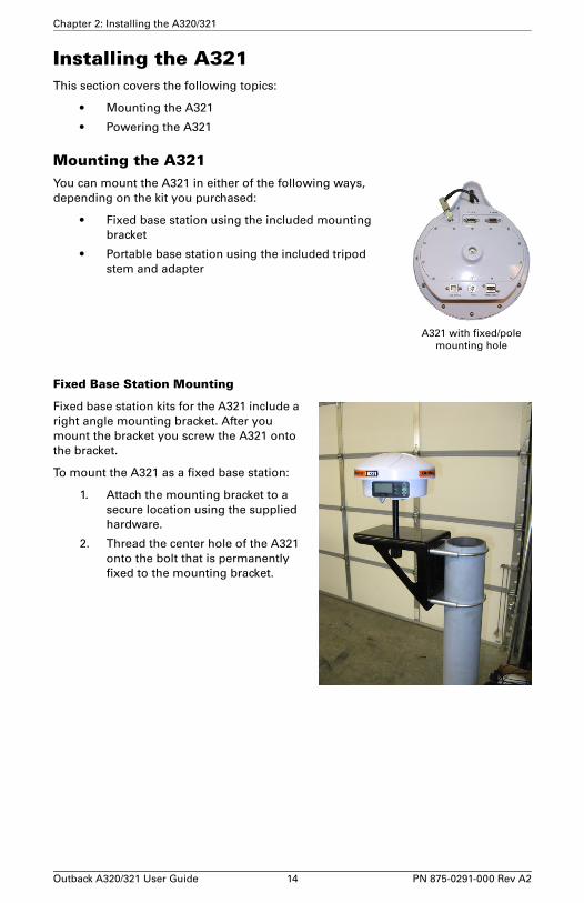
Mounting the A321You can mount the A321 in either of the following ways, depending on the kit you purchased:
• Fixed base station using the included mounting bracket
• Portable base station using the included tripod stem and adapter
Fixed Base Station Mounting
Fixed base station kits for the A321 include a right angle mounting bracket. After you mount the bracket you screw the A321 onto the bracket.
To mount the A321 as a fixed base station:
1. Attach the mounting bracket to a secure location using the supplied hardware.
2. Thread the center hole of the A321 onto the bolt that is permanently fixed to the mounting bracket.
A321 with fixed/polemounting hole
Outback A320/321 User Guide 14 PN 875-0291-000 Rev A2
Chapter 2: Installing the A320/321
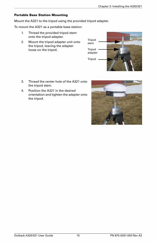
Portable Base Station Mounting
Mount the A321 to the tripod using the provided tripod adapter.
To mount the A321 as a portable base station:
1. Thread the provided tripod stem onto the tripod adapter.
2. Mount the tripod adapter unit onto the tripod, leaving the adapter loose on the tripod.
3. Thread the center hole of the A321 onto the tripod stem.
4. Position the A321 in the desired orientation and tighten the adapter onto the tripod.
Tripod
Tripod
Tripod
adapter
stem
Outback A320/321 User Guide 15 PN 875-0291-000 Rev A2

Chapter 2: Installing the A320/321
Powering the A321Depending on the parts included in your A321 kit you can the power the A321 via either of the following:
• 110/220 V AC power cable
• Power cable (terminated with battery clips) to connect to a 12 V battery*
*You can use a 12 V car battery or, if you purchased a portable base station kit, you can use the included 12 V battery
The A321 is automatically “on” upon connecting a power source.
Note: The following procedure describes how to connect the A321 to a 12 V car battery using the power cable (terminated with battery clips) included in some A321 kits. If your kit includes the 110/220 V AC power cable connect the power cable to a suitable power source in step 2.
To connect a power source to the A321:
1. Connect the provided power cable to the A321’s power port. See Figure 1-3 on page 5 for the location of the power port.
2. Attach the positive and negative leads at the opposite end of the power cable to the positive and negative terminals of a car battery.
Note: If you purchased the portable base station kit, the connection to the 12 V battery is the same as shown at right.
3. Check the Power LED on the A321—a red LED indicates a successful connection and the A321 has power. See “LED Indicators” on page 7 for more information on the display panel LEDs.
Power cable connectedto battery
A321 connectedto battery
Power LED is on (red)
Outback A320/321 User Guide 16 PN 875-0291-000 Rev A2

Chapter 3: Operating the A320/321Using the Menus
A320/321 Radio Configuration Overview
Configuring Your A320/321 400 MHz Microhard Radio
Configuring Your A320/321 900 MHz Microhard Radio
Operating the A320
Operating the A321
Outback A320/321 User Guide 17 PN 875-0291-000 Rev A2

Chapter 3: Operating the A320/321
This chapter provides an overview of using the menu system as well as basic configuration and operation instructions for your A320/321:
• For using your A320 see “Operating the A320” on page 38
• For using your A321 see “Operating the A321” on page 47
Using the MenusThe A321 includes a menu system you access from the display panel; see “A321 Display Panel” on page 6 for a brief overview. Although the A320 does not include a menu system accessible from its display panel, you can use Hemisphere GPS’ Remote Control software to perform many of the same tasks that you can with the A321’s menu system. Even though the A321 has a physical display panel, you can use Remote Control with the A321 as well.
Note: The following sections refer to the A321 physical display panel or the A320 or A321 using Remote Control software.
Obtaining and Setting Up Remote Control SoftwareRemote Control is available from the Outback Guidance website.
1. Open a web browser and go to www.outbackguidance.com.
2. Navigate to Support > Precision > Software.
3. Click the Remote Control link and save the download to your PC.
4. Install the software.
To use Remote Control software you must connect your A320/321 to your PC (on which Remote Control is installed) using a serial cable. Just power on your receiver and start Remote Control and you can begin using the software.
Comparing Remote Control Software to the A321 Physical Display PanelFigure 3-1 shows the physical display panel of the A321 alongside the Remote Control software display panel.
Note: There is a slight delay (a second or so) when using Remote Control (the screen may not refresh immediately).
Figure 3-1: A321 display panel vs. Remote Control display panel
A321 display panel Remote Control display panel
Outback A320/321 User Guide 18 PN 875-0291-000 Rev A2

Chapter 3: Operating the A320/321
GNSS Signal Level Display
Figure 3-2: A321 menu
As shown in Figure 3-2 the channel bars above the menu visually display each channel's tracking status (one bar section for each channel) as follows:
• When tracking L1 GPS only, each bar represents L1 GPS.
• When tracking L1/L2 GPS, each bar is two separate bars (starting from the left, first bar for L1 GPS, second bar for L2 GPS)
• When tracking L1/L2 GPS and GLONASS, each bar is four separate bars (starting from the left, first bar for L1 GPS, second bar for L2 GPS, third bar for L1 GLONASS, fourth bar for L2 GLONASS)
Note: If you have a GLONASS subscription, the first menu item on the Top menu is GNSS. If you do not have a GLONASS subscription, the first menu item is GPS.
Navigating the Menus and Selecting Menu ItemsWhether you are using the physical display on the A321 or you have an A320 or A321 connected to a PC and are running Remote Control, on startup the Top menu appears.
Figure 3-3: Top menu
Channelbars
Outback A320/321 User Guide 19 PN 875-0291-000 Rev A2

Chapter 3: Operating the A320/321
The A320/321 front panel contains three soft buttons: Up Arrow, Enter, and Down Arrow (see Figure 3-4).
Figure 3-4: Menu buttons
In addition to selecting items you can return to previous menu levels using the following menus items:
• Select Back to return to the previous menu level
• Select Top Menu to return to the Top menu
Table 3-1 describes the indicators that appear to the right of specific menu items.
Table 3-1: Menu item indicators
Indicator Purpose Example
Display indicator
Go to the indicated submenu
This indicator also appears to the right of the “Back” and “Top Menu” menu items.
• Pressing Enter when “Back” is selected returns you to the previous menu.
• Pressing Enter when “Top Menu” is selected returns you to the Top menu.
1. On the Top menu press the Down Arrow button to highlight System Setup. The Display indicator appears to the right of System Setup.
2. Press Enter to display the System Setup menu.
3. Press the Down Arrow button again to highlight the Display Format option and then press Enter. The items on the Display Format menu appear and the Select indicator appears to the right of Disp Update (the first item on the Display Format menu).
4. Press Enter on the Disp Update item. The Display indicator changes to the Select indicator.
5. Press the Up Arrow or Down Arrow button to scroll through the available options (such as 1Hz and 5Hz).
6. Press Enter on the highlighted option to select it. That option is now the setting for the menu item and the Select indicator changes back to the Display indicator.
Select indicator
Scrolls within a menu to highlight an option to select.
Up Arrow button
Enter button
Down Arrow button
(scroll up through items)
(scroll down through items)
(select an item)
Outback A320/321 User Guide 20 PN 875-0291-000 Rev A2

Chapter 3: Operating the A320/321
Menu and Menu Item Selection in This User GuideFor many instructions in this User Guide the following example illustrates the nomenclature used for navigating the menus.
“On the Top menu select Data Logging > Config” is the equivalent to saying “On the Top menu select Data Logging and press Enter. Then select Config and press Enter.”
When making selections for a menu item, such as selecting Yes or No for Auto-Name (Data Logging > Config menu), the instructions will indicate to select the menu item and press Enter to allow you to then select an option for that menu item and then press Enter again to select that option.
Entering Alphanumeric Characters
Use the Up Arrow and Down Arrow buttons to enter alphanumeric characters (for example, when entering a job name or a subscription code).
To enter alphanumeric characters:
1. At the prompt, press the Down Arrow button to scroll to the desired character.
The character appears on a black background when the prompt is active.
2. Press Enter to select the character. The prompt moves to the next character.
3. Press Enter when done.
Top Menu OverviewRefer to Appendix B, “Menu Map” for a complete menu map for the following options on the Top menu:
• GPS/GNSS
• Differential corrections (menu item will be the selected differential source, such as SBAS or Autonomous)
• Base Station (A321 only)
• Config (configuration) Wizard
• System Setup
• Data Logging
DownArrowbutton
Enterbutton
Outback A320/321 User Guide 21 PN 875-0291-000 Rev A2

Chapter 3: Operating the A320/321
A320/321 Radio Configuration OverviewIf your A320/321 antenna has an optional radio use the information in this section to configure the A320/321 to set the following:
• Radio mode of operation
• Channel/frequency
• Power
Note: The radio mode and channel/frequency of the A320 rover must match that of the A321 base station for the A320 rover to successfully receive the broadcasted RTK messages.
Some configuration steps will differ slightly depending on the type of radio you have installed in your A320/321.
• If you have a Microhard 400 MHz radio installed go to “Configuring Your A320/321 400 MHz Microhard Radio” below.
• If you have a Microhard 900 MHz radio installed go to “Configuring Your A320/321 900 MHz Microhard Radio” on page 32.
Additionally, for the 400 MHz radio you can encrypt RTK data using the Microhard radio static mask (see page 28).
Configuring Your A320/321 400 MHz Microhard Radio
Setting the Radio Mode of OperationThe radio mode refers to a Hemisphere GPS-proprietary mode or a number of industry-standard compatible modes—see Table 3-2 on page 24 for more information on supported radio modes.
Note: The following steps show how to use Remote Control software to set the mode. Follow the same steps if using the actual menu on the A321 to set its mode.
Outback A320/321 User Guide 22 PN 875-0291-000 Rev A2

Chapter 3: Operating the A320/321
Complete the following steps to set the radio mode:
Step Base Station Screen Item Rover Screen Item
Base Station
1. On the Top menu scroll to and select Base Station.
Rover
1. On the Top menu scroll to and select RTK.
2. Scroll to (if necessary) and select Radio.
3. Scroll to and select Mode.
4. Use the Up Arrow and Down Arrow buttons to display the desired mode and press Enter to select the mode.
Outback A320/321 User Guide 23 PN 875-0291-000 Rev A2

Chapter 3: Operating the A320/321
Table 3-2 describes the available radio modes. Pac Crest provides a configuration tool that allows you to view the parameters in the Description column; therefore, select the mode you need based on these parameters (PC1 and PC3 differ only by the FEC parameter: ON or OFF).
Note: Hemisphere GPS recommends PC1 for most applications. You should only use PC3 if your are trying to maintain compatibility with an existing Pac Crest network.
Setting the Frequency
You must obtain a valid radio license for your jurisdiction before using the A320/321 with 400 MHz radio. Only set the radio to the frequency and power you are licensed to use at your location.
Each A321 base station and A320 rover in a network must be configured to operate on the same frequency.
You can set the frequency to any value between 410 MHz and 480 MHz. The frequency must be a multiple of 0.0125 MHz (12.5 kHz). If you enter an invalid frequency, it will be rejected with an “INVALID” error.
Note: The following steps show how to use Remote Control software to set the frequency. Follow the same steps if using the actual menu on the A321 to set its frequency.
Table 3-2: 400 MHz Microhard radio modes
Mode Description Comment
PC1 9600 bps link rate, GMSK, FEC ON, Scrambling ON
Compatible with Pac Crest and Satel. This is the most common mode of operation and generally provides the best distance performance. Throughput is limited to approximately 5600 bits/sec.
PC2 Future mode, currently not supported
PC3 9600 bps link rate, GMSK, FEC OFF, Scrambling ON
Compatible with Pac Crest. This mode provides slightly inferior distance performance compared to PC1, but provides better throughput of approximately 8300 bits/sec.
PC4 Future mode, currently not supported
HGPS 16000 bps link rate, FEC OFF, Scrambling ON
This mode is similar to PC3, but provides better throughput of approximately 14000 bit/sec, while still maintaining excellent sensitivity. This mode also allows setup of network repeaters and retransmissions.
Outback A320/321 User Guide 24 PN 875-0291-000 Rev A2

Chapter 3: Operating the A320/321
Complete the following steps to set the frequency:
Step Base Station Screen Item Rover Screen Item
Base Station
1. On the Top menu scroll to and select Base Station.
Rover
1. On the Top menu scroll to and select RTK.
2. Scroll to (if necessary) and select Radio.
3. Scroll to and select Freq.
Outback A320/321 User Guide 25 PN 875-0291-000 Rev A2

Chapter 3: Operating the A320/321
Setting the Power
Note: The following steps show how to use Remote Control software to set the power. Follow the same steps if using the actual menu on the A321 to set its power.
Complete the following steps to set the power:
4. To set the frequency:
a. Use the Up Arrow and Down Arrow buttons to set the first digit and then press Enter. After pressing Enter the next digit to the right is highlighted.
b. Repeat step a for each digit.
Note: When you press Enter to set the last digit, the frequency is set and the select indicator changes to the display indicator (you can now use the Up Arrow and Down Arrow buttons to highlight other Radio options such as Type and RSSI).
Step Base Station Screen Item Rover Screen Item
Base Station
1. On the Top menu scroll to and select Base Station.
Rover
1. On the Top menu scroll to and select RTK.
2. Scroll to (if necessary) and select Radio.
Step Base Station Screen Item Rover Screen Item
Outback A320/321 User Guide 26 PN 875-0291-000 Rev A2

Chapter 3: Operating the A320/321
The A321 is capable of transmitting at an output power ranging from 0.1 W (20 dBm) up to 5 W (37 dBm) in 1 dB increments. Hemisphere GPS recommends that you set the power to the highest level allowable by your license.
If battery life is a concern, you may want to start with the highest allowable power setting on the A321 base station and back it off to the lowest level that still provides adequate RF coverage for your location.
The radio is the main contributor to battery drain; therefore, backing off on the transmit power allows for significantly longer discharge times. Table 3-3 lists typical A321 power consumption.
3. Scroll to and select Power.
4. Use the Up Arrow and Down Arrow buttons to display the desired power and press Enter to select the power.
Table 3-3: Typical A320/321 power consumption
Radio TX Power Setting
Typical Total Outback A321 Power Consumption
Typical Battery Discharge Time of 18Ah SLA Battery
20 dBm (0.1 W) 7.2 W 31 hours
27 dBm (0.5 W) 9.0 W 25.0 hours
30 dBm (1 W) 10.4 W 21.5 hours
33 dBm (2 W) 12.6 W 17.5 hours
35 dBm (3 W) 14.1 W 15.5 hours
37 dBm (5 W) 18.0 W 11.8 hours
Step Base Station Screen Item Rover Screen Item
Outback A320/321 User Guide 27 PN 875-0291-000 Rev A2

Chapter 3: Operating the A320/321
Encrypting RTK Data Using the Microhard Radio Static MaskWhen configuring a Microhard radio you can set the static mask to encrypt (require a password to access) RTK data. The default static mask for the 400 MHz radio is blank (no static mask).
Before you set the static mask, make sure you are running the latest version of Remote Control software. To obtain the latest version of Remote Control, visit www.outbackguidance.com and navigate to Support > Precision > Software.
You can connect to the A320/321 via Remote Control or a terminal window.
Setting the Static Mask Using Remote Control
1. Connect to the A320/321 on Port A.
2. Start Remote Control and on the UHF Radio tab click Advanced.
This takes the radio offline, passes through to the radio data port, and presents the current radio configuration (shown at right).
The static mask is parameter S107 and is shown in the output as:
Static Mask S107=****
3. Type ATS107=xxxxxxxx in the drop-down box and then press Enter (or click SEND) to change the static mask, where xxxxxxxx represents the static mask you want to use.
If successfully set, the radio will reply with OK.
Receive mode only 5.7 W 39 hours
Note: Typically the rover (A320) is always in receive mode and the base station (A321) is always in transmit mode.
Table 3-3: Typical A320/321 power consumption (continued)
Radio TX Power Setting
Typical Total Outback A321 Power Consumption
Typical Battery Discharge Time of 18Ah SLA Battery
Outback A320/321 User Guide 28 PN 875-0291-000 Rev A2

Chapter 3: Operating the A320/321
4. Send the command AT&W to save the settings.
5. Click QUIT to return to normal operating mode.
Note: To remove the static mask (remove encryption) repeat the above procedure but in step 4 type ATS107= in the drop-down box (do not type anything after the “=”).
Setting the Static Mask Using a Terminal Window
1. Connect to the A320/321 on Port A.
2. Start the terminal program on your PC. Make sure the baud rate of your PC port matches that of the A320/321.
3. Send the command $JRELAY,PORTC,$MENUREPLY,A
4. Send the command $JRELAY,PORTC,$JRADIO,PROGRAMMODE to take the radio offline, pass through to the radio data port, and present the current radio configuration.
The static mask is parameter S107 and is shown in the output as:
Static Mask S107=****
5. Type ATS107=xxxxxxxx to change the static mask:
where xxxxxxxx represents the static mask you want to use. If successfully set, the radio will reply with OK.
6. Send the command AT&W to save the settings.
7. Type QUIT (uppercase) to return to normal operating mode.
Outback A320/321 User Guide 29 PN 875-0291-000 Rev A2

Chapter 3: Operating the A320/321
Typical Distance PerformanceDistance performance is dependent on several factors including:
• Base station antenna height
• Base station antenna gain
• Cable losses
• Base station transmit power
• Rover antenna gain
• Rover antenna height
• Receiver (rover) sensitivity
• Terrain
Hemisphere GPS’ high performance 400 MHz radio solution, when properly installed, can provide up to 30 km of RTK coverage from one base station location. Figure 3-5 approximates the distance performance you can expect.
Figure 3-5: Typical RTK distance performance vs. base station antenna height above ground
Outback A320/321 User Guide 30 PN 875-0291-000 Rev A2

Chapter 3: Operating the A320/321
The expected range is based on the following assumptions:
• Gently rolling hills
• Medium to low vegetation
• High quality, low loss RF cables at base station
• Base station uses Hemisphere GPS recommended 5 dBi antenna
• Base station Tx power is set to 3 W
• Rover antenna height is 3 m above ground level
• Frequency of operation is 450 MHz
• Mode of operation is PC1 (9600 bps GMSK, FEC ON)
As shown in Figure 3-5 base station antenna height is key to RTK performance. When installing your base station, find a location on a structure, preferably at the highest elevation available.
At 2m (6ft) base antenna height above ground, typical RTK distance performance is approximately 8 km (5 mi). However, as you raise the base station antenna, this range improves dramatically. At 20 m (65 ft) above ground level, rovers can expect to typically receive RTK corrections at distances up to about 28 km (17 mi).
It is important to use high quality RF cable at the base station. Hemisphere GPS provides high-quality RF cables in lengths of 15, 30, or 45 m.
Normally, the A321 will be located close to ground level, while the 400 MHz UHF antenna will be mounted on a structure several meters above ground. This requires a fairly long run of cable. Figure 3-6 illustrates the typical degradation in distance performance (for four different base station antenna heights) as you use longer runs of RF cable.
Figure 3-6: Typical RTK distance performance vs. RF cable length at base station for four base station antenna heights above ground
Typical Base-Rover Communication Range vs. Cable LengthBased on CCIR Path Loss Model - Plots show distance vs. cable length for four different
base antenna heights. Transmitter is 450 MHz at 3 W. Rover antenna height is 3 m.
Outback A320/321 User Guide 31 PN 875-0291-000 Rev A2

Chapter 3: Operating the A320/321
Configuring Your A320/321 900 MHz Microhard Radio
Setting the Radio Mode of OperationThe radio mode refers to a number of Hemisphere GPS-proprietary modes that are optimized for certain message types and environments. See Table 3-4 on page 33 for more information on supported radio modes.
Note: The following steps show how to use Remote Control software to set the mode. Follow the same steps if using the actual menu on the A321 to set its mode.
Complete the following steps to set the radio mode:
Step Base Station Screen Item Rover Screen Item
Base Station
1. On the Top menu scroll to and select Base Station.
Rover
1. On the Top menu scroll to and select RTK.
2. Scroll to (if necessary) and select Radio.
Outback A320/321 User Guide 32 PN 875-0291-000 Rev A2

Chapter 3: Operating the A320/321
Table 3-4 describes the available Hemisphere GPS-proprietary radio modes. Hemisphere GPS recommends FAST mode for most applications.
Note: The Microhard MHX920-FS 900 MHz radio is proprietary and will not communicate with other RTK manufacturers’ equipment.
3. Scroll to and select Mode.
4. Use the Up Arrow and Down Arrow buttons to display the desired mode and press Enter to select the mode.
Table 3-4: 900 MHz Microhard radio modes
Mode Description Comment
SLOW 19200 bit/s RF link rate with forward error correction (FEC)
Compatible with previously-released MHX920-SL1 (Part No. 808-1003-000) radio kit. Lowest data throughput of all the modes. Not recommended for new installations.
SLOW is required for use on older 900 MHz radios available from Hemisphere GPS.
SLOW2 19200 bit/s RF link rate with no FEC
Improved data throughput over SLOW mode. Suitable for use in low-noise environments with A320/321.
FAST 115200 bit/s RF link rate with no FEC
Superior data throughput allows RTK messages to be rebroadcast multiple times per second. Provides the best performance in most applications.
FAST is required for GLONASS on the A320/A321.
Step Base Station Screen Item Rover Screen Item
Outback A320/321 User Guide 33 PN 875-0291-000 Rev A2

Chapter 3: Operating the A320/321
Setting the ChannelYou can set the channel to any value between 1 and 100.
Each A321 base station and A320 rover in a network must be configured to operate on the same channel.
Note: The following steps show how to use Remote Control software to set the channel. Follow the same steps if using the actual menu on the A321 to set its channel.
Complete the following steps to set the channel:
Step Base Station Screen Item Rover Screen Item
Base Station
1. On the Top menu scroll to and select Base Station.
Rover
1. On the Top menu scroll to and select RTK.
2. Scroll to (if necessary) and select Radio.
Outback A320/321 User Guide 34 PN 875-0291-000 Rev A2

Chapter 3: Operating the A320/321
Setting the Power
Note: The following steps show how to use Remote Control software to set the power. Follow the same steps if using the actual menu on the A321 to set its power.
3. Scroll to and select Channel.
4. Use the Up Arrow and Down Arrow buttons to display the desired channel and then press Enter.
Note: When you press Enter to set the last digit, the channel is set and the select indicator changes to the display indicator (you can now use the Up Arrow and Down Arrow buttons to highlight other Radio options such as Type and RSSI).
Step Base Station Screen Item Rover Screen Item
Outback A320/321 User Guide 35 PN 875-0291-000 Rev A2

Chapter 3: Operating the A320/321
Complete the following steps to set the power:
Step Base Station Screen Item Rover Screen Item
Base Station
1. On the Top menu scroll to and select Base Station.
Rover
1. On the Top menu scroll to and select RTK.
2. Scroll to (if necessary) and select Radio.
3. Scroll to and select Power.
4. Use the Up Arrow and Down Arrow buttons to display the desired power and press Enter to select the power.
Outback A320/321 User Guide 36 PN 875-0291-000 Rev A2

Chapter 3: Operating the A320/321
The Microhard MHX920-FS radio in the A321 is capable of transmitting at an output power ranging from 0.1 W (20 dBm) up to 1 W (30 dBm) in 1 dB increments. Hemisphere GPS recommends that you set the power to the maximum (1 W / 30 dBm) for most applications.
Checking VSWRVoltage standing wave ratio (VSWR) provides an indication of any RF cabling or antenna problems and can be read on the base station menu interface.
VSWR has the following characteristics:
• The lower the number the better.
• Anything below 2 generally indicates the cabling and antenna are installed correctly.
• If the value is above 2, check that the cable and antenna are securely installed and that there is no visible damage.
The VSWR reading is updated approximately every 30 seconds.
Checking RSSIReceived signal strength indicator (RSSI) is a status update of the strength of the signal received at the rover, and can be read on the rover’s menu interface.
• The higher the number the better (for example, -90 is better than -100).
• Typically, an RSSI of -100 and better is acceptable for reliably receiving RTK messages from the base station.
• If the value is below -100, steps should be taken to improve signal strength. The best way to do this is to raise the height of the base station antenna.
Table 3-5: Typical A320/321 power consumption
Radio TX Power Setting
Typical Total Outback A321 Power Consumption
Typical Battery Discharge Time of 18Ah SLA Battery
20 dBm (0.1 W) 7.2 W 31 hours
27 dBm (0.5 W) 9.0 W 25.0 hours
30 dBm (1 W) 10.4 W 21.5 hours
Receive mode only 5.7 W 39 hours
Note: Typically the rover (A320) is always in receive mode and the base station (A321) is always in transmit mode.
Outback A320/321 User Guide 37 PN 875-0291-000 Rev A2

Chapter 3: Operating the A320/321
Operating the A320
Quick StartInitial startup may take from 5 to 15 minutes, depending on your geographic location. For example, it may take up to 5 minutes to receive a full ionospheric map from SBAS to ensure optimum accuracy.
1. Verify the A320 and all connected systems are powered on. When you turn the switch on the power cable to the “ON” position the red LED illuminates (indicating power).
See “LED Indicators” on page 7 for more information on the A320 LED indicators.
2. Enter a receiver authorization code (optional). See “Adding Additional Receiver Authorizations” on page 38.
3. Configure GPS options. See “Configuring GPS Settings with Outback S3” below.
4. Activate L-band service (optional). See “Activating L-Band Service” on page 46.
5. Wait for the A320 to converge on a differential signal. A green LED indicates DGPS. You are ready to begin using your A320.
Configuring GPS Settings with Outback S3Configuring the A320 for use with an S3 involves the following steps:
1. (Optional) Adding additional receiver authorizations, such as RTK or GLONASS, after purchase (see page 38)
2. Setting basic configuration options (see below)
3. (Optional) Activating L-band service (see page 46)
You must connect the A320 to the S3 and power on both the A320 and the S3 before using the S3 to configure the A320.
Adding Additional Receiver Authorizations
The A320 allows you to add additional authorizations, such as RTK or GLONASS, after purchase.
To add additional receiver authorizations:
StepScreen Item (when applicable)
1. On the S3 touch the Setup screen tab. The Setup screen appears.
Outback A320/321 User Guide 38 PN 875-0291-000 Rev A2

Chapter 3: Operating the A320/321
2. Touch the Codes button. The Codes screen appears.
3. Touch the A320 Subscription field. The External GNSS Features List window appears.
StepScreen Item (when applicable)
Outback A320/321 User Guide 39 PN 875-0291-000 Rev A2

Chapter 3: Operating the A320/321
Setting Basic Configuration Options
Using the GPS screens on the S3 you can set the following options on your A320:
• DGPS application type, such as SBAS, RTK, or L-band
• Baud rate and NMEA (output) message rates
• Radio (optional) - set the mode of operation and frequency of the A320’s internal radio
Note: If using the A320 with a non-Outback product, refer to the Hemisphere GPS Technical Reference (go to www.hemispheregps.com/support and click the GPS Reference icon). The Technical Reference lists the commands needed to change baud rates, radio parameters, NMEA message output rates, and applications.
4. Touch the Enter Code button. The Enter Code screen appears.
5. Enter your authorization code and touch the Apply button. The code is applied and the Enter Code screen closes.
StepScreen Item (when applicable)
Outback A320/321 User Guide 40 PN 875-0291-000 Rev A2

Chapter 3: Operating the A320/321
Note: The GPS Only button on the GPS Setup screen and the Use All GNSS button on the NMEA screen work together as follows:
• To use GPS and GLONASS for positioning and NMEA message output, the Use All GNSS button must be orange and the GPS ONLY button must be blue.
• If the Use All GNSS button is blue (regardless of the color of the GPS Only button), GLONASS is not used for positioning or NMEA message output.
• If the Use All GNSS button is orange and the GPS Only button is orange, GLONASS is not used for positioning or NMEA message output.
• If the GPS Only button is orange, the Use All GNSS button can be toggled but does not change any functionality.
To set the DGPS application type on the S3:
StepScreen Item(when applicable)
1. On the S3 touch the GPS tab. The GPS Setup screen appears. Depending on what GPS screen you viewed previously, you may need to touch the Setup button to display the GPS Setup screen.
Note: For information on the GPS Only button see the Note at the top of this page.
2. In the GPS Source area verify A320 is selected (button is orange).
Outback A320/321 User Guide 41 PN 875-0291-000 Rev A2

Chapter 3: Operating the A320/321
To set the A320 baud rate and NMEA (output) message rates:
3. In the Choose GPS Application area, touch the desired differential corrections application button. Application types include: SBAS, RTK, and L-Band.
For more information on the available configurations for your A320 contact your Outback Guidance dealer or Outback Guidance Customer Service.
The Radio and RTK Status buttons are only active after you select RTK as the application type.
Note: L-band functionality requires a subscription; contact your L-band service provider for more information.
4. If you select RTK as the application touch the RTK Status button to display the RTK Status screen.
Note: If you see an alert on this screen your RTK performance is at risk and you should investigate the reason as described on this screen.
StepScreen Item(when applicable)
1. On the S3 touch the GPS screen tab. The GPS Setup screen appears.
StepScreen Item(when applicable)
Outback A320/321 User Guide 42 PN 875-0291-000 Rev A2

Chapter 3: Operating the A320/321
2. Touch the NMEA button. The NMEA screen appears.
If necessary touch the A320 button in the upper left of the screen to display NMEA settings for the A320.
Note: For information on the Use All GNSS button see the Note at the top of page 41.
3. Touch the BAUD Up Arrow or Down Arrow button to cycle through the available baud rates.
4. For each message output rate you want to set touch the desired message Up Arrow or Down Arrow button to cycle through the available rates (GLL message arrows shown at right).
StepScreen Item(when applicable)
Outback A320/321 User Guide 43 PN 875-0291-000 Rev A2

Chapter 3: Operating the A320/321
To set the radio mode and frequency:
StepScreen Item(when applicable)
1. On the S3 touch the GPS screen tab. The GPS Setup screen appears. Depending on what GPS screen you viewed previously, you may need to touch the Setup button to display the GPS Setup screen.
2. Verify the following:
• A320 is selected in the GPS Source area
• RTK is selected in the Choose GPS Application area
and then touch the Radio button. The Radio screen appears with the radio type in the non-editable Status field (in the screen following, Microhard L400 appears in the Status field). The Radio Mode and Frequency fields are editable.
Outback A320/321 User Guide 44 PN 875-0291-000 Rev A2

Chapter 3: Operating the A320/321
3. To set the radio mode:
a. Touch the Radio Mode field. The Radio Mode window appears.
b. Select the desired mode and touch Ok.
4. To set the frequency:
a. Touch the Frequency field. The Edit Frequency window appears.
b. Touch the Up Arrow and Down Arrow buttons to set each segment of the frequency value and touch Ok.
StepScreen Item(when applicable)
Outback A320/321 User Guide 45 PN 875-0291-000 Rev A2

Chapter 3: Operating the A320/321
Activating L-Band Service
The A320 is enabled for L-band service; however, you must first contact your L-band service provider to activate the service.
To activate L-band service:
StepScreen Item (when applicable)
1. Verify the A320 is connected to the S3 and that all systems are powered on.
2. Make sure the vehicle is stationary and the antenna has a clear view of the sky.
3. Using the GPS Details screen below perform the following:
a. Monitor the number of satellites tracked in the Sats Tracked field to ensure a proper GPS signal.
b. Locate the Serial Number field and contact your L-band service provider to activate service for your region.
Typically it takes up to 15 minutes for the activation to take effect; however, some activations may take longer.
c. Monitor the value in the STDEV field to confirm a converged signal. Contact your L-band service provider to determine how long this may take.
You can operate the vehicle while waiting for a converged signal but you will experience decreased accuracy.
If you turned on the A320 in the same location you turned it off with a converged L-band signal, the time required to reach maximum accuracy is reduced.
4. When the system converges on an L-band signal, you are ready to use your L-band service.
Outback A320/321 User Guide 46 PN 875-0291-000 Rev A2

Chapter 3: Operating the A320/321
Operating the A321On startup the A321 displays the Top menu. You can access all the setup menus from the Top menu. The A321 menu system is designed for easy setup and configuration of the unit in or out of the field.
This section includes the following topics:
• Begin using the A321 (below)
• Operating modes - fixed base station vs. portable base station (page 49)
• Setting the A321 as a fixed base station (page 49)
• Setting the A321 as a portable base station (page 53)
• Setting an alternate reference point (page 53)
• Managing configurations (page 54)
• USB data logging (page 55)
Begin Using the A321Complete the following steps to begin using the base station:
StepScreen Item (when applicable)
1. Plan the base station location. The A321 base station automatically uses its current location as the reference point. Place the base station in a location:
• With an unobstructed view of the sky
• At least 50 meters (160 feet) from any obstructions
Figure 3-7: Location of the base station
2. Select the desired radio channel/frequency. Base and rover configurations must match (for 900 MHz radios you set the channel; for 400 MHz radios you set the frequency).
5 m
(16.4 ft)
50 m (160 ft)
Outback A320/321 User Guide 47 PN 875-0291-000 Rev A2

Chapter 3: Operating the A320/321
a. On the Top menu, select Base Station > Radio. The Radio screen displays the radio manufacturer, version number, and channel/frequency.
b. Press Enter to select the Channel field.
c. Use the Up Arrow and Down Arrow buttons to select the desired channel and then press Enter to save.
d. Select Back to return to the previous menu.
3. Wait for RTK lock (maximum accuracy). The screen will cycle through the following displays.
Note: It takes 3 - 5 minutes for the base station to achieve RTK lock in an unknown location. It typically takes the base station less than 60 seconds to achieve RTK lock in a known location.
You are ready to use your A321 base station.
StepScreen Item (when applicable)
Countdown to
Position lock
GPS Position
position lock
Status screen
Outback A320/321 User Guide 48 PN 875-0291-000 Rev A2

Chapter 3: Operating the A320/321
Base Station Operating ModesThe A321 can operate in two base station modes:
• Fixed (permanent) base station modeTypical Use: If year-after-year A-B line repeatability is expected for controlled traffic farming, you must use this option from the first use.
• Portable base station modeTypical Use: Quick and easy solution for temporary job or one-time-only contract site.
A fixed location ensures the A321 uses the same reference coordinates every time and they do not unintentionally change; otherwise, an unwanted jump in the rover’s offset position from one RTK session to the next may occur (such as a tractor following an A-B line that is offset by several centimeters up to several meters from one RTK session to the next).
Fixed mode is intended for an A321 that is permanently mounted in a fixed location (such as on a radio tower or other permanent structure), where you are satisfied with its coverage and you will use it for RTK coverage of the same area from day to day, season to season.
If you install the A321 within 50 m of the fixed coordinates, it will use these reference coordinates for its RTK solution. The reference coordinates remain the same (are not affected by a power cycle or excessive drift in GPS solution) until you manually change them. The A321 will never use an alternate reference location. If the current solution drifts more than 50 m from these reference coordinates the A321 stops broadcasting the RTK message.
As shown in Figure 3-8, you use the FixedLoc menu setting to set your A321 as a fixed base station (set to YES) or a portable base station (set to NO).
Figure 3-8: Operating modes (FixedLoc setting)
To navigate to the FixedLoc setting:
• From the Top menu, select Base Station > Reference > FixedLoc.
Setting the A321 as a Fixed Base StationWhen setting a fixed location for your base station you have the following options:
• Entering new reference information manually
• Using the unit’s current position
• Using an average of the unit’s current position (averaging occurs for 300 sec)
Note: In areas of ionospheric activity re-averaging the unit’s position (third bullet above) may provide the most reliable location information.
Fixed base station mode Portable base station mode
Outback A320/321 User Guide 49 PN 875-0291-000 Rev A2

Chapter 3: Operating the A320/321
Manually Entering Fixed Coordinates
You can manually enter base station coordinates before or after installing the A321. For example, if you know the exact installation location and you first enter the coordinates, the person installing the A321 can simply install it and power it up.
To fix the base station location to a manually-entered coordinates:
StepScreen Item (when applicable)
1. On the Top menu, select Base Station > Reference > FixedLoc.
2. Use the Up Arrow or Down Arrow button to change the value to Yes and then press Enter.
Note: For information on entering/editing values see “Navigating the Menus and Selecting Menu Items” on page 19.
3. Select Enter New. Lt, Ln, and Hgt are displayed with Lt highlighted.
4. Enter the desired coordinate information: latitude (Lt), longitude (Ln), and height (Hgt).
5. Scroll to and select Set Reference. The screen changes to show the Time To Go and then Time To Go changes to Converged (if the unit converges on the coordinates).
Outback A320/321 User Guide 50 PN 875-0291-000 Rev A2

Chapter 3: Operating the A320/321
Setting the Base Station Fixed Location to Its Current Location
Note: You should only use this option after the A321 is installed and has converged.
To set the base station fixed location as the current position:
Setting the Base Station Fixed Location to an Average of Positions
Note: You should only use this option after the A321 is installed.
The A321 re-averages its position for 5 minutes (300 seconds) and assigns this new position to its permanent reference coordinates.
StepScreen Item (when applicable)
1. On the Top menu, select Base Station > Reference > FixedLoc.
2. Use the Up Arrow or Down Arrow button to change the value from No to Yes and then press Enter.
3. Scroll to and select Use Current Pos. The screen changes to show the Time To Go and then Time To Go changes to Converged (if the unit converges on the coordinates).
Outback A320/321 User Guide 51 PN 875-0291-000 Rev A2

Chapter 3: Operating the A320/321
To set the base station fixed location to an average of positions:
StepScreen Item (when applicable)
1. On the Top menu, select Base Station > Reference > FixedLoc.
2. Use the Up Arrow or Down Arrow button to change the value from No to Yes and then press Enter.
3. Scroll to and select Re-Average Pos. The screen changes to show the Time To Go and the A321 counts down from 300 seconds to zero, after which Time To Go changes to Converged (if the unit converges on the coordinates).
Outback A320/321 User Guide 52 PN 875-0291-000 Rev A2

Chapter 3: Operating the A320/321
Setting the A321 as a Portable Base StationTo set the A321 as a portable base station:
Setting an Alternate Reference PointTo set an alternate reference point:
StepScreen Item (when applicable)
1. On the Top menu, select Base Station > Reference > FixedLoc.
2. Use the Up Arrow or Down Arrow button to change the value from Yes to No and then press Enter.
StepScreen Item (when applicable)
1. On the Top menu, select Base Station > Reference > Set New Reference > Enter New.
2. Enter the desired coordinates.
Outback A320/321 User Guide 53 PN 875-0291-000 Rev A2

Chapter 3: Operating the A320/321
Managing ConfigurationsThe A321 Configuration Wizard allows you to:
• Save a configuration
• Return to a saved configuration
• Delete a saved configuration
Saving a Configuration
To save a configuration:
Returning to a Saved Configuration
To return to a saved configuration:
StepScreen Item (when applicable)
1. On the Top menu, select Config Wizard > Proceed Wizard > Create New.
2. Select Enter Name, use the Up Arrow and Down Arrow buttons to enter a name, then press Enter.
3. Scroll to and select Save to Location.
4. Scroll to the desired location (such as Not Used1) and press Enter to save.
StepScreen Item (when applicable)
1. On the Top menu, select Config Wizard > Use Previous.
Outback A320/321 User Guide 54 PN 875-0291-000 Rev A2

Chapter 3: Operating the A320/321
Deleting a Saved Configuration
To delete a saved configuration:
USB Data LoggingWhen you insert a USB flash drive into the A321, the Data Logging menu indicates you can start recording (logging data) and displays the free space on the flash drive (see Figure 3-9). When you start logging data the “Start Recording” indicator changes to “End <filename>.”
Figure 3-9: USB flash drive indicators on Data Logging menu
Stop data logging before removing the USB flash drive from the Outback A321. Failure to do so may result in a loss of data.
2. Scroll to the desired configuration and press Enter to select it.
StepScreen Item (when applicable)
1. On the Top menu, select Config Wizard > Delete Saved.
2. Select the desired configuration and press Enter to delete it.
Note: Once you press Enter, the saved configuration is permanently deleted.
StepScreen Item (when applicable)
With no USB flash drive inserted With USB flash drive inserted
Outback A320/321 User Guide 55 PN 875-0291-000 Rev A2


Appendix A: Technical Specifications
Outback A320/321 User Guide 57 PN 875-0291-000 Rev A2

Appendix A: Technical Specifications
Table A-1 through Table A-6 provide the sensor, horizontal accuracy, communication, power, environmental, and mechanical specifications for the A320/321.
Table A-1: GPS/GNSS sensor specifications
Item Specification
Receiver type GNSS L1 and L2 RTK with carrier phase
Channels 12 L1CA GPS12 L1P GPS12 L2P GPS (with subscription code)12 L2C GPS (with subscription code)12 L1 GLONASS (with subscription code)12 L2 GLONASS (with subscription code)3 SBAS or 3 additional L1CA GPS1 L-Band
SBAT tracking 3-channel, parallel tracking
Update rate 10 Hz standard, 20 Hz available (with subscription)
Timing (1PPS) Accuracy: 20 ns
Startup time < 60 s typical (no almanac or RTC)< 30 s typical (almanac and RTC)< 10 s typical (almanac, RTC and position)
Maximum speed 1,850 kph (999 kts)
Maximum altitude 18,288 m (60,000 ft)
Differential options SBAS, Autonomous, External RTCM, RTK, L-band
Table A-2: Horizontal accuracy
Item Specification
RMS (67%) 2DRMS (95%)
RTK1,2 10 mm+1 ppm 20 mm+2 ppm
L-band high precision service1,3 0.1 m 0.2 m
SBAS (WAAS)1 0.3 m 0.6 m
Autonomous, no SA1 1.2 m 2.5 m
Table A-3: Communication specifications
Item Specification
A320 A321
CAN 1x N/A
USB 1x USB-A 1x USB-B
Serial 2x 2x (Bluetooth adapter support)
PPS 1x 1x
Outback A320/321 User Guide 58 PN 875-0291-000 Rev A2

Appendix A: Technical Specifications
Data I/O protocol NMEA 0183 NMEA 0183, binary, NMEA 2000 binary
Correction I/O protocol Hemisphere GPSproprietary, RTCM v2.3(DGPS), RTCM v3 (RTK),
CMR, CMR+4
Table A-4: Power specifications
Item Specification
Input voltage 9 - 36 VDC
Power consumption (With no radio) 5 W @ 12 VDC +/-10%
(With radio) 400 MHzradio
900 MHzradio
Radio TX power setting Power consumption
20 dBm (0.1 W)27 dBm (0.5 W)30 dBm (1 W)33 dBm (2 W)35 dBm (3 W)37 dBm (5 W)Receive mode only
7.2 W9.0 W10.4 W12.6 W14.1 W18.0 W5.7 W
7.2 W9.0 W10.4 W
N/AN/AN/A
5.7 W
Current consumption 400 mA @ 12 VDC (with no radio)
Table A-5: Environmental specifications
Item Specification
Operating temperature -30° C to +65° C (-22° F to +149° F)
Storage temperature -40° C to +85° C (-40° F to +185° F)
Enclosure IP67, EP455
Compliance FCC, CE
Table A-6: Mechanical specifications
Item Specification
Dimensions 150 mm H x 244 mm D (5.9 in H x 9.6 in D)
Material Magnesium alloy/plastic
Mount Screw/magnetic mount or 5/8” tripod mount
Enclosure Waterproof, dust proof
Weight 1.8 kg (4.0 lbs)
Table A-3: Communication specifications (continued)
Item Specification
Outback A320/321 User Guide 59 PN 875-0291-000 Rev A2

Appendix A: Technical Specifications
1 Depends on multipath environment, number of satellites in view, satellite geometry, and ionospheric activity.
2 Depends also on baseline length.
3 Requires a subscription from L-band service provider.
4 Receive only, does not transmit this format.
Outback A320/321 User Guide 60 PN 875-0291-000 Rev A2

Appendix B: Menu MapTop Menu
GPS/GNSS Menu
SBAS Menu
Base Station Menu
Config Wizard Menu
System Setup Menu
Data Logging Menu
Outback A320/321 User Guide 61 PN 875-0291-000 Rev A2

Appendix B: Menu Map
Top MenuUse the Top menu to access the submenus.
If you have a GLONASS subscription, the first menu item on the Top menu is GNSS
If you do not have a GLONASS subscription, the first menu item on the Top menu is GPS
Outback A320/321 User Guide 62 PN 875-0291-000 Rev A2

Appendix B: Menu Map
GPS/GNSS MenuUse the GPS/GNSS menu to view position status, individual satellite data, or to change GNSS settings, such as the elevation mask or maximum DGPS age.
Outback A320/321 User Guide 63 PN 875-0291-000 Rev A2

Appendix B: Menu Map
SBAS MenuUse the SBAS menu to view differential signal status.
Outback A320/321 User Guide 64 PN 875-0291-000 Rev A2

Appendix B: Menu Map
Base Station MenuUse the Base Station menu to view radio details, set an alternate reference point, return to using your current position, or re-average your position.
After you set a referencethe “Time To Go” itemchanges to “Converged”and the “Show Reference”item appears above the“SetNewReference” item whenyou press the Down Arrow toscroll down.
Outback A320/321 User Guide 65 PN 875-0291-000 Rev A2

Appendix B: Menu Map
Config Wizard MenuUse the Config Wizard menu to work with configurations (save a configuration, return to a saved configuration, and delete a saved configuration).
Outback A320/321 User Guide 66 PN 875-0291-000 Rev A2

Appendix B: Menu Map
System Setup MenuUse the System Setup menu to configure basic system options, including the differential type, display format (units, update rate of the display), baud rates, display screen contrast, subscription number, or language.
Outback A320/321 User Guide 67 PN 875-0291-000 Rev A2

Appendix B: Menu Map
Data Logging MenuUse the Data Logging menu to log job data. Tasks include naming your data log, selecting whether to include receiver information in the log file, selecting the file type of your log file, and starting and stopping your log file.
Outback A320/321 User Guide 68 PN 875-0291-000 Rev A2

Appendix C: Using Remote ControlStarting Remote Control
Radio Tab
Base Station Tab
Outback A320/321 User Guide 69 PN 875-0291-000 Rev A2

Appendix C: Using Remote Control
Remote Control is a free Hemisphere GPS software application you can use to set up and configure an A320/321. To obtain Remote Control visit www.outbackguidance.com and navigate to Support > Precision > Software.
Starting Remote ControlBefore starting Remote Control you must connect the A320/321 to your PC via serial cable. Connect one end of a serial cable to the serial port of the A320/321 and connect the other end of the cable to your PC.
1. Start Remote Control.
2. Click the Connect button to display a list of all available serial ports on your PC.
3. Click the appropriate port. Remote Control searches for and finds the receiver and automatically requests information from the receiver.
Remote Control includes three tabs:
• Remote LCD - Displays the same information (menu, LEDs, and buttons) as on the A321 display. For detailed information on the menu, LEDs, and buttons see “Display Panel” on page 6. If you are using an A320, you can still use the Remote LCD tab via the serial port connection.
• Radio - Allows you to set radio parameters.
• Base Station - Allows you to set up multiple base station locations and manually set the reference station locations stored in the receiver. See “Base Station Tab” on page 72 for more information.
Radio TabThe Radio tab is only enabled if your A320/321 includes an internal radio.
Microhard Radio InstalledThe Radio tab for Microhard radios allows you to edit specific radio parameters related to the configuration of the device.
The Radio tab looks similar to one of the following, depending on your installed radio:
There are predefined modes of operation for the radios. See Table 3-2 on page 24 and Table 3-4 on page 33 for more information on the radio modes.
400 MHz radio installed 900 MHz radio installed
Outback A320/321 User Guide 70 PN 875-0291-000 Rev A2

Appendix C: Using Remote Control
The radio in the unit is self-configuring based on the application being used. The radio is automatically set up as a:
• Rover (receiving) radio for units running the RTK application
• Base (transmitting) radio for units running the SBASRTKB application
Note: Press the Save button to keep any changes you make on the Radio tab.
Advanced Radio ControlThe Advanced Radio Control option allows you to access the internal radio directly via radio manufacturer’s radio commands. When using Remote Control, the software checks for a specific registry key. If it is present, the Advanced button on the Radio tab is enabled.
Note: Only advanced users should edit these parameters. Setting incorrect values may cause radios to stop communicating with one another.
To edit internal radio parameters:
1. On the Radio tab click the Advanced button (see figure above). This takes the radio offline and displays the Remote Control configuration screen (shown at right). You can edit any configurable parameter in the radio.
2. Enter the appropriate command in the text box and then click the SEND button.
3. When complete, click the QUIT button to return to the Radio tab.
Outback A320/321 User Guide 71 PN 875-0291-000 Rev A2

Appendix C: Using Remote Control
Base Station TabThe Base Station tab allows you to set up multiple base station locations and manually set the reference station locations stored in the receiver. The A321 supports up to 32 base station coordinates. The receiver must be running the SBASRTKB application and you must have an RTK subscription for the function to be enabled.
Upon connecting to the receiver, Remote Control automatically queries the receiver for its list of known coordinates.
After a successful query Remote Control displays a list of existing base station coordinates. If the receiver has converged on a reference point, the converged coordinates will appear with a * next to the #, as seen below.
Once the coordinates list is populated you can perform the following tasks:
• Add coordinates
• Import or export coordinates
• Delete coordinates
Note: You must click the Save button before exiting Remote Control to save your changes (adding, deleting, and importing coordinates).
Converged reference pointCoordinates list
Outback A320/321 User Guide 72 PN 875-0291-000 Rev A2

Appendix C: Using Remote Control
If you do not want the receiver to have the base station coordinate list active, clear the Enable Base Station List check box.
You can change the coordinate format between decimal degrees (DD.D), degrees and decimal minutes (DM.M), or degree minutes and decimal seconds (DMS). Any change to this value also affects the coordinates displayed on the LCD.
Adding Base Station Coordinates
To add coordinates to the list:
1. Make sure the Enable Base Station List check box is selected.
2. Select the appropriate format from the Coordinate Format drop-down list.
3. Enter the desired latitude, longitude, and height values in the Lat, Lon, and Height fields.
4. Click the Add button. The new coordinates point (Lat/Lon/Height) is added to the coordinates list.
5. Click the Save button to save your changes.
Importing/Exporting Base Station Coordinates
Importing and exporting the coordinates list is compatible with previous legacy base station applications.
To import coordinates from a file:
1. Make sure the Enable Base Station List check box is selected.
2. Right-click the coordinates list, and from the pop-up menu click Import Coordinates.
3. In the Open window navigate to and select the coordinates file you want to import and click Open.
The coordinates from the file are added to the coordinates list on the Base Station tab.
4. Click the Save button to save your changes.
Outback A320/321 User Guide 73 PN 875-0291-000 Rev A2

Appendix C: Using Remote Control
To export coordinates to a file:
1. Make sure the Enable Base Station List check box is selected.
2. Right-click the coordinates list, and from the pop-up menu click Export Coordinates.
3. In the Open window navigate to the location where you want to export the coordinates and click Open.
The coordinates are exported.
Deleting Base Station Coordinates
To delete a coordinates point from the list:
1. Make sure the Enable Base Station List check box is selected.
2. In the coordinates list select the coordinates point you want to delete (the coordinates point is highlighted).
3. Right-click the coordinates point you selected, and from the pop-up menu click Delete #<coords #>.
The coordinates point is deleted.
4. Click the Save button to save your changes.
To delete all coordinates from the list:
1. Make sure the Enable Base Station List check box is selected.
2. Right-click the coordinates list, and from the pop-up menu click Delete All Coordinates.
The coordinates are deleted.
3. Click the Save button to save your changes.
Outback A320/321 User Guide 74 PN 875-0291-000 Rev A2

Index
Numerics1PPS (timing accuracy) specification 58
AA231
operating 47A320
configuring with Outback S3 38connections 4display panel 6LED indicators 7operating 38ports 4quick start 38radio configuration (400 MHz) 22radio configuration (900 MHz) 32
A321base station modes 49begin using 47connections 5deleting a configuration 55display panel 6, 18fixed base station 49LED indicators 7managing configurations 54manually entering fixed coordinates
50portable base station 53ports 5radio configuration (400 MHz) 22radio configuration (900 MHz) 32re-averaging fixed location 51Remote Control display 18returning to a configuration 54saving a configuration 54setting alternate reference point 53setting fixed location to current loca-
tion 51activating
L-band service 46adding
receiver authorizations 38antenna
overview 2port 4, 5
authorizationsadding to receiver 38
autonomous accuracy specification 58
Bbase station
deleting all coordinates 74deleting specific coordinates point 74exporting coordinates 74fixed 49importing coordinates 73manually setting up fixed base 50portable 53re-averaging fixed base 51using current location 51
Base Station menu 65Base Station tab (Remote Control) 72baud rate
setting for radio 42
CCAN port specification 58channel
setting for 400 MHz radio 24setting for 900 MHz radio 34
channels specification 58compliance specification 59Config Wizard menu 66configuration
deleting (base station) 55returning to saved (base station) 54saving (base station) 54
connectionsA320 4A321 5mounting hole 5
coordinatesdeleting a specific point (base station)
74deleting all (base station) 74exporting (base station) 74importing (base station) 73
correction I/O protocol specification 59current consumption specification 59
Ddat I/O protocol specification 59data logging
overview 55Data Logging menu 68deleting
all coordinates (base station) 74configuration (base station) 55specific coordinates point (base sta-
tion) 74DGPS application type
setting for radio 41
Outback A320/321 User Guide 75 PN 875-0291-000 Rev A2

Index
DGPS LED 7differential options specification 58dimensions specification 59display indicator 20display panel
A320 6A321 6
Down button 20
EEclipse II 2enclosure (environmental) specification59enclosure (mechanical) specification 59encrypting RTK data 28Enter button 20exporting
coordinates (base station) 74
Ffeatures 3fixed base station
manually entering coordinates 50re-averaging location 51setting up 49using current location 51
frequencysetting for 400 MHz radio 24setting for radio 44
GGPS LED 7GPS/GNSS menu 63
Iimporting
coordinates (base station) 73input voltage specification 59
Kkey features 3
LL-band
accuracy specification 58activating service 46
LED indicators 7DGPS 7GPS 7power 7
Mmaterial specification 59maximum altitude specification 58
maximum speed specification 58menu map
Base Station menu 65Config Wizard menu 66Data Logging menu 68GPS/GNSS menu 63SBAS menu 64System Setup menu 67Top menu 62
menusbuttons 20item indicators 20
message output ratesetting for radio 42
Microhard 7mode of operation
setting for 400 MHz radio 22setting for 900 MHz radio 32
mount specification 59mounting hole 5
NNMEA message output rate
setting for radio 42
Ooperating temperature specification 59Outback S3
configuring GPS settings (A320) 38introduction to 2
overview 2
Pportable base station
setting up 53ports
A320 4A321 5antenna 4, 5power 4, 5serial 5
powersetting for 400 MHz radio 26setting for 900 MHz radio 35
power consumptionA320/321 with 900 MHz radio 37specification 59
power LED 7power port 4, 5PPS communication specification 58
Rradio modes
400 MHz radio 24900 MHz radio 33
Outback A320/321 User Guide 76 PN 875-0291-000 Rev A2

Index
radio options 7radio parameters
editing using Remote Control 71Radio tab (Remote Control) 70received signal strength indicator 37receiver
LED indicators 7logging data 55
receiver specifications 58autonomous accuracy 58CAN port 58channels 58compliance 59correction I/O protocol 59current consumption 59data I/O protocol 59differential options 58dimensions 59enclosure (environmental) 59enclosure (mechanical) 59input voltage 59L-band accuracy 58material 59maximum altitude 58maximum speed 58mount 59operating temperature 59power consumption 59PPS communication 58receiver type 58RTK accuracy 58SBAS accuracy 58SBAS tracking 58serial port 58startup time 58storage temperature 59timing accuracy 58update rate 58USB port 58weight 59
receiver type specification 58Remote Control
Base Station tab 72editing radio parameters 71Radio tab 70
returning to a saved configuration (basestation) 54RSSI, see received signal strength indica-tor 37RTK accuracy specification 58
Ssaving
configuration (base station) 54SBAS accuracy specification 58SBAS menu 64
SBAS tracking specification 58select indicator 20serial port 5serial port specification 58setting
channel (400 MHz radio) 24channel (900 MHz radio) 34DGPS application type 41frequency (400 MHz radio) 24message output rate 42mode of operation (400 MHz radio) 22mode of operation (900 MHz radio) 32NMEA message output rate 42power (400 MHz radio) 26power (900 MHz radio) 35radio baud rate 42radio frequency 44
specifications, see receiver specifications58startup time specification 58static mask 28storage temperature specification 59System Setup menu 67
Ttiming accuracy specification 58Top menu 62
UUp button 20update rate specification 58USB data logging 55USB port specification 58
Vvoltage standing wave ration 37VSWR, see voltage standing wave ration37
Wweight specification 59what’s included 3
Outback A320/321 User Guide 77 PN 875-0291-000 Rev A2


End User License AgreementIMPORTANT - This is an agreement (the "Agreement") between you, the end purchaser ("Licensee") and Hemisphere GPS Inc. ("Hemisphere") which permits Licensee to use the Hemisphere software (the "Software") that accompanies this Agreement. This Software may be licensed on a standalone basis or may be embedded in a Product. Please read and ensure that you understand this Agreement before installing or using the Software Update or using a Product.
In this agreement any product that has Software embedded in it at the time of sale to the Licensee shall be referred to as a "Product". As well, in this Agreement, the use of a Product shall be deemed to be use of the Software which is embedded in the Product.
BY INSTALLING OR USING THE SOFTWARE UPDATE OR THE PRODUCT, LICENSEE THEREBY AGREES TO BE LEGALLY BOUND BY THE TERMS OF THIS AGREEMENT. IF YOU DO NOT AGREE TO THESE TERMS, (I) DO NOT INSTALL OR USE THE SOFTWARE, AND (II) IF YOU ARE INSTALLING AN UPDATE TO THE SOFTWARE, DO NOT INSTALL THE UPDATE AND PROMPTLY DESTROY IT.
HEMISPHERE PROVIDES LIMITED WARRANTIES IN RELATION TO THE SOFTWARE. AS WELL, THOSE WHO USE THE EMBEDDED SOFTWARE DO SO AT THEIR OWN RISK. YOU SHOULD UNDERSTAND THE IMPORTANCE OF THESE AND OTHER LIMITATIONS SET OUT IN THIS AGREEMENT BEFORE INSTALLING OR USING THE SOFTWARE OR THE PRODUCT.
1. LICENSE. Hemisphere hereby grants to Licensee a non-transferable and non-exclusive license to use the Software as embedded in a Product and all Updates (collectively the "Software"), solely in binary executable form.
2. RESTRICTIONS ON USE. Licensee agrees that Licensee and its employees will not directly or indirectly, in any manner whatsoever:
a. install or use more copies of the Software than the number of copies that have been licensed;
b. use or install the Software in connection with any product other than the Product the Software was intended to be used or installed on as set out in the documentation that accompanies the Software.
c. copy any of the Software or any written materials for any purpose except as part of Licensee's normal backup processes;
d. modify or create derivative works based on the Software;
e. sub-license, rent, lease, loan or distribute the Software;
f. permit any third party to use the Software;
g. use or operate Product for the benefit of any third party in any type of service outsourcing, application service, provider service or service bureau capacity;
h. reverse engineer, decompile or disassemble the Software or otherwise reduce it to a human perceivable form;
i. Assign this Agreement or sell or otherwise transfer the Software to any other party except as part of the sale or transfer of the whole Product.
3. UPDATES. At Hemisphere's discretion Hemisphere may make Updates available to Licensee. An update ("Update") means any update to the Software that is made available to Licensee including error corrections, enhancements and other modifications. Licensee may access, download and install Updates during the Warranty Period only. All Updates that Licensee downloads, installs or uses shall be deemed to be Software and subject to this Agreement. Hemisphere reserves the right to modify the Product without any obligation to notify, supply or install any improvements or alterations to existing Software.
4. SUPPORT. Hemisphere may make available directly or through its authorized dealers telephone and email support for the Software. Contact Hemisphere to find the authorized dealer near you. As well, Hemisphere may make available user and technical documentation regarding the Software. Hemisphere reserves the right to reduce and limit access to such support at any time.
5. BACKUPS AND RECOVERY. Licensee shall back-up all data used, created or stored by the Software on a regular basis as necessary to enable proper recovery of the data and related systems and processes in the event of a malfunction in the Software or any loss or corruption of data caused by the Software. Licensee shall assume all risks of loss or damage for any failure to comply with the foregoing.
6. OWNERSHIP. Hemisphere and its suppliers own all rights, title and interest in and to the Software and related materials, including all intellectual property rights. The Software is licensed to Licensee, not sold.
7. TRADEMARKS. "Hemisphere GPS", "Outback Guidance", "BEELINE", "Crescent", "Eclipse" and the associated logos are trademarks of Hemisphere. Other trademarks are the property of their respective owners. Licensee may not use any of these trademarks without the consent of their respective owners.
8. LIMITED WARRANTY. Hemisphere warrants solely to the Licensee, subject to the exclusions and procedures set forth herein below, that for a period of one (1) year from the original date of purchase of the Product in which it is embedded (the "Warranty Period"), the Software, under normal use and maintenance, will conform in all material respects to the documentation provided with the Software and any media will be free of defects in materials and workmanship. For any Update, Hemisphere warrants, for 90 days from performance or delivery, or for the balance of the original Warranty Period, whichever is greater, that the Update, under normal use and maintenance, will conform in all material respects to the documentation provided with the Update and any media will be free of defects in materials and workmanship. Notwithstanding the foregoing, Hemisphere does not warrant that the Software will meet Licensee's requirements or that its operation will be error free.
9. WARRANTY EXCLUSIONS. The warranty set forth in Section (8) will not apply to any deficiencies caused by (a) the Product not being used as described in the documentation supplied to Licensee, (b) the Software having been altered, modified or converted in any way by anyone other than Hemisphere approved by Hemisphere, (c) any malfunction of Licensee's equipment or other software, or (d) damage occurring in transit or due to any accident, abuse, misuse, improper installation, lightning (or other electrical discharge) or neglect other than that caused by Hemisphere. Hemisphere GPS does not warrant or guarantee the precision or accuracy of positions obtained when using the Software (whether standalone or embedded in a Product). The Product and the Software is not intended and should not be used as the primary means of navigation or for use in safety of life applications. The potential

positioning and navigation accuracy obtainable with the Software as stated in the Product or Software documentation serves to provide only an estimate of achievable accuracy based on specifications provided by the US Department of Defense for GPS positioning and DGPS service provider performance specifications, where applicable.
10. WARRANTY DISCLAIMER. EXCEPT AS EXPRESSLY SET OUT IN THIS AGREEMENT, HEMISPHERE MAKES NO REPRESENTATION, WARRANTY OR CONDITION OF ANY KIND TO LICENSEE, WHETHER VERBAL OR WRITTEN AND HEREBY DISCLAIMS ALL REPRESENTATIONS, WARRANTIES AND CONDITIONS OF ANY KIND INCLUDING FITNESS FOR A PARTICULAR PURPOSE, MERCHANTABILITY, ACCURACY, RELIABILITY OR THAT THE USE OF THE SOFTWARE WILL BE UNINTERRUPTED OR ERROR-FREE AND HEREBY DISCLAIMS ALL REPRESENTATIONS, WARRANTIES AND CONDITIONS ARISING AS A RESULT OF CUSTOM, USAGE OR TRADE AND THOSE ARISING UNDER STATUTE.
11. LIMITS ON WARRANTY DISCLAIMER. Some jurisdictions do not allow the exclusion of implied warranties or conditions, so some of the above exclusions may not apply to Licensee. In that case, any implied warranties or conditions which would then otherwise arise will be limited in duration to ninety (90) days from the date of the license of the Software or the purchase of the Product. The warranties given herein give Licensee specific legal rights and Licensee may have other rights which may vary from jurisdiction to jurisdiction.
12. CHANGE TO WARRANTY. No employee or agent of Hemisphere is authorized to change the warranty provided or the limitation or disclaimer of warranty provisions. All such changes will only be effective if pursuant to a separate agreement signed by senior officers of the respective parties.
13. WARRANTY CLAIM. In the event Licensee has a warranty claim Licensee must first check for and install all Updates that are made available. The warranty will not otherwise be honored. Proof of purchase may be required. Hemisphere does not honor claims asserted after the end of the Warranty Period.
14. LICENSEE REMEDIES. In all cases which involve a failure of the Software to conform in any material respect to the documentation during the Warranty Period or a breach of a warranty, Hemisphere's sole obligation and liability, and Licensee's sole and exclusive remedy, is for Hemisphere, at Hemisphere's option, to (a) repair the Software, (b) replace the Software with software conforming to the documentation, or (c) if Hemisphere is unable, on a reasonable commercial basis, to repair the Software or to replace the Software with conforming software within ninety (90) days, to terminate this Agreement and thereafter Licensee shall cease using the Software. Hemisphere will also issue a refund for the price paid by Licensee less an amount on account of amortization, calculated on a straight-line basis over a deemed useful life of three (3) years.
15. LIMITATION OF LIABILITY. IN NO EVENT WILL HEMISPHERE BE LIABLE TO LICENSEE FOR ANY INCIDENTAL, CONSEQUENTIAL, SPECIAL OR INDIRECT DAMAGES INCLUDING ARISING IN RELATION TO ANY LOSS OF DATA, INCOME, REVENUE, GOODWILL OR ANTICIPATED SAVINGS EVEN IF HEMISPHERE HAS BEEN INFORMED OF THE POSSIBILITY OF SUCH LOSS OR DAMAGE. FURTHER, IN NO EVENT WILL HEMISPHERE'S TOTAL CUMULATIVE LIABILITY HEREUNDER, FROM ALL CAUSES OF ACTION OF ANY KIND, EXCEED THE TOTAL AMOUNT PAID BY LICENSEE TO HEMISPHERE TO PURCHASE THE PRODUCT. THIS LIMITATION AND EXCLUSION APPLIES IRRESPECTIVE OF THE CAUSE OF ACTION, INCLUDING BUT NOT LIMITED TO BREACH OF CONTRACT, NEGLIGENCE, STRICT LIABILITY, TORT, BREACH OF WARRANTY, MISREPRESENTATION OR ANY OTHER LEGAL THEORY AND WILL SURVIVE A FUNDAMENTAL BREACH.
16. LIMITS ON LIMITATION OF LIABILITY. Some jurisdictions do not allow for the limitation or exclusion of liability for incidental or consequential damages, so the above limitation or exclusion may not apply to Licensee and Licensee may also have other legal rights which may vary from jurisdiction to jurisdiction.
17. BASIS OF BARGAIN. Licensee agrees and acknowledges that Hemisphere has set its prices and the parties have entered into this Agreement in reliance on the limited warranties, warranty disclaimers and limitations of liability set forth herein, that the same reflect an agreed-to allocation of risk between the parties (including the risk that a remedy may fail of its essential purpose and cause consequential loss), and that the same forms an essential basis of the bargain between the parties. Licensee agrees and acknowledges that Hemisphere would not have been able to sell the Product at the amount charged on an economic basis without such limitations.
18. PROPRIETARY RIGHTS INDEMNITY. Hemisphere shall indemnify, defend and hold harmless Licensee from and against any and all actions, claims, demands, proceedings, liabilities, direct damages, judgments, settlements, fines, penalties, costs and expenses, including royalties and attorneys' fees and related costs, in connection with or arising out of any actual infringement of any third party patent, copyright or other intellectual property right by the Software or by its use, in accordance with this Agreement and documentation, PROVIDED THAT: (a) Hemisphere has the right to assume full control over any action, claim, demand or proceeding, (b) Licensee shall promptly notify Hemisphere of any such action, claim, demand, or proceeding, and (c) Licensee shall give Hemisphere such reasonable assistance and tangible material as is reasonably available to Licensee for the defense of the action, claim, demand or proceeding. Licensee shall not settle or compromise any of same for which Hemisphere has agreed to assume responsibility without Hemisphere's prior written consent. Licensee may, at its sole cost and expense, retain separate counsel from the counsel utilized or retained by Hemisphere.
19. INFRINGEMENT. If use of the Software may be enjoined due to a claim of infringement by a third party then, at its sole discretion and expense, Hemisphere may do one of the following: (a) negotiate a license or other agreement so that the Product is no longer subject to such a potential claim, (b) modify the Product so that it becomes non-infringing, provided such modification can be accomplished without materially affecting the performance and functionality of the Product, (c) replace the Software, or the Product, with non-infringing software, or product, of equal or better performance and quality, or (d) if none of the foregoing can be done on a commercially reasonable basis, terminate this license and Licensee shall stop using the Product and Hemisphere shall refund the price paid by Licensee less an amount on account of amortization, calculated on a straight-line basis over a deemed useful life of three (3) years.
The foregoing sets out the entire liability of Hemisphere and the sole obligations of Hemisphere to Licensee in respect of any claim that the Software or its use infringes any third party rights.
20. INDEMNIFICATION. Except in relation to an infringement action, Licensee shall indemnify and hold Hemisphere harmless from any and all claims, damages, losses, liabilities, costs and expenses (including reasonable fees of lawyers and other professionals) arising out of or in connection with Licensee's use of the Product, whether direct or indirect, including without limiting the foregoing, loss of data, loss of profit or business interruption.

21. TERMINATION. Licensee may terminate this Agreement at any time without cause. Hemisphere may terminate this Agreement on 30 days notice to Licensee if Licensee fails to materially comply with each provision of this Agreement unless such default is cured within the 30 days. Any such termination by a party shall be in addition to and without prejudice to such rights and remedies as may be available, including injunction and other equitable remedies. Upon receipt by Licensee of written notice of termination from Hemisphere or termination by Licensee, Licensee shall at the end of any notice period (a) cease using the Software; and (b) return to Hemisphere (or destroy and provide a certificate of a Senior Officer attesting to such destruction) the Software and all related material and any magnetic or optical media provided to Licensee. The provisions of Sections 6), 7), 8), 9), 10), 15), 21), 26) and 27) herein shall survive the expiration or termination of this Agreement for any reason.
22. EXPORT RESTRICTIONS. Licensee agrees that Licensee will comply with all export control legislation of Canada, the United States, Australia and any other applicable country's laws and regulations, whether under the Arms Export Control Act, the International Traffic in Arms Regulations, the Export Administration Regulations, the regulations of the United States Departments of Commerce, State, and Treasury, or otherwise as well as the export control legislation of all other countries.
23. PRODUCT COMPONENTS. The Product may contain third party components. Those third party components may be subject to additional terms and conditions. Licensee is required to agree to those terms and conditions in order to use the Product.
24. FORCE MAJEURE EVENT. Neither party will have the right to claim damages as a result of the other's inability to perform or any delay in performance due to unforeseeable circumstances beyond its reasonable control, such as labor disputes, strikes, lockouts, war, riot, insurrection, epidemic, Internet virus attack, Internet failure, supplier failure, act of God, or governmental action not the fault of the non-performing party.
25. FORUM FOR DISPUTES. The parties agree that the courts located in Calgary, Alberta, Canada and the courts of appeal there from will have exclusive jurisdiction to resolve any disputes between Licensee and Hemisphere concerning this Agreement or Licensee's use or inability to use the Software and the parties hereby irrevocably agree to attorn to the jurisdiction of those courts. Notwithstanding the foregoing, either party may apply to any court of competent jurisdiction for injunctive relief.
26. APPLICABLE LAW. This Agreement shall be governed by the laws of the Province of Alberta, Canada, exclusive of any of its choice of law and conflicts of law jurisprudence.
27. CISG. The United Nations Convention on Contracts for the International Sale of Goods will not apply to this Agreement or any transaction hereunder.
28. GENERAL. This is the entire agreement between Licensee and Hemisphere relating to the Product and Licensee's use of the same, and supersedes all prior, collateral or contemporaneous oral or written representations, warranties or agreements regarding the same. No amendment to or modification of this Agreement will be binding unless in writing and signed by duly authorized representatives of the parties. Any and all terms and conditions set out in any correspondence between the parties or set out in a purchase order which are different from or in addition to the terms and conditions set forth herein, shall have no application and no written notice of same shall be required. In the event that one or more of the provisions of this Agreement is found to be illegal or unenforceable, this Agreement shall not be rendered inoperative but the remaining provisions shall continue in full force and effect.

Warranty NoticeCOVERED PRODUCTS: This warranty covers all products manufactured by Hemisphere GPS and purchased by the end purchaser (the "Products"), unless otherwise specifically and expressly agreed in writing by Hemisphere GPS.
LIMITED WARRANTY: Hemisphere GPS warrants solely to the end purchaser of the Products, subject to the exclusions and procedures set forth below, that the Products sold to such end purchaser and its internal components shall be free, under normal use and maintenance, from defects in materials, and workmanship and will substantially conform to Hemisphere GPS’s applicable specifications for the Product, for a period of 12 months from delivery of such Product to such end purchaser (the ”Warranty Period”). Repairs and replacement components for the Products are warranted, subject to the exclusions and procedures set forth below, to be free, under normal use and maintenance, from defects in material and workmanship, and will substantially conform to Hemisphere GPS’s applicable specifications for the Product, for 90 days from performance or delivery, or for the balance of the original Warranty Period, whichever is greater.
EXCLUSION OF ALL OTHER WARRANTIES. The LIMITED WARRANTY shall apply only if the Product is properly and correctly installed, configured, interfaced, maintained, stored, and operated in accordance with Hemisphere GPS’s relevant User’s Manual and Specifications, AND the Product is not modified or misused. The Product is provided “AS IS” and the implied warranties of MERCHANTABILITY and FITNESS FOR A PARTICULAR PURPOSE and ALL OTHER WARRANTIES, express, implied or arising by statute, by course of dealing or by trade usage, in connection with the design, sale, installation, service or use of any products or any component thereof, are EXCLUDED from this transaction and shall not apply to the Product. The LIMITED WARRANTY is IN LIEU OF any other warranty, express or implied, including but not limited to, any warranty of MERCHANTABILITY or FITNESS FOR A PARTICULAR PURPOSE, title, and non-infringement.
LIMITATION OF REMEDIES. The purchaser’s EXCLUSIVE REMEDY against Hemisphere GPS shall be, at Hemisphere GPS’s option, the repair or replacement of any defective Product or components thereof. The purchaser shall notify Hemisphere GPS or a Hemisphere GPS’s approved service center immediately of any defect. Repairs shall be made through a Hemisphere GPS approved service center only. Repair, modification or service of Hemisphere GPS products by any party other than a Hemisphere GPS approved service center shall render this warranty null and void. The remedy in this paragraph shall only be applied in the event that the Product is properly and correctly installed, configured, interfaced, maintained, stored, and operated in accordance with Hemisphere GPS’s relevant User’s Manual and Specifications, AND the Product is not modified or misused. NO OTHER REMEDY (INCLUDING, BUT NOT LIMITED TO, SPECIAL, INDIRECT, INCIDENTAL, CONSEQUENTIAL OR CONTINGENT DAMAGES FOR LOST PROFITS, LOST SALES, INJURY TO PERSON OR PROPERTY, OR ANY OTHER INCIDENTAL OR CONSEQUENTIAL LOSS) SHALL BE AVAILABLE TO PURCHASER, even if Hemisphere GPS has been advised of the possibility of such damages. Without limiting the foregoing, Hemisphere GPS shall not be liable for any damages of any kind resulting from installation, use, quality, performance or accuracy of any Product.
HEMISPHERE IS NOT RESPONSIBLE FOR PURCHASER’S NEGLIGENCE OR UNAUTHORIZED USES OF THE PRODUCT. IN NO EVENT SHALL HEMISPHERE GPS BE IN ANY WAY RESPONSIBLE FOR ANY DAMAGES RESULTING FROM PURCHASER’S OWN NEGLIGENCE, OR FROM OPERATION OF THE PRODUCT IN ANY WAY OTHER THAN AS SPECIFIED IN HEMISPHERE GPS’S RELEVANT USER’S MANUAL AND SPECIFICATIONS. Hemisphere GPS is NOT RESPONSIBLE for defects or performance problems resulting from (1) misuse, abuse, improper installation, neglect of Product; (2) the utilization of the Product with hardware or software products, information, data, systems, interfaces or devices not made, supplied or specified by Hemisphere GPS; (3) the operation of the Product under any specification other than, or in addition to, the specifications set forth in Hemisphere GPS’s relevant User’s Manual and Specifications; (4) damage caused by accident or natural events, such as lightning (or other electrical discharge) or fresh/salt water immersion of Product; (5) damage occurring in transit; (6) normal wear and tear; or (7) the operation or failure of operation of any satellite-based positioning system or differential correction service; or the availability or performance of any satellite-based positioning signal or differential correction signal.
THE PURCHASER IS RESPONSIBLE FOR OPERATING THE VEHICLE SAFELY. The purchaser is solely responsible for the safe operation of the vehicle used in connection with the Product, and for maintaining proper system control settings. UNSAFE DRIVING OR SYSTEM CONTROL SETTINGS CAN RESULT IN PROPERTY DAMAGE, INJURY, OR DEATH. The purchaser is solely responsible for his/her safety and for the safety of others. The purchaser is solely responsible for maintaining control of the automated steering system at all times. THE PURCHASER IS SOLELY RESPONSIBLE FOR ENSURING THE PRODUCT IS PROPERLY AND CORRECTLY INSTALLED, CONFIGURED, INTERFACED, MAINTAINED, STORED, AND OPERATED IN ACCORDANCE WITH HEMISPHERE GPS’S RELEVANT USER’S MANUAL AND SPECIFICATIONS. Hemisphere GPS does not warrant or guarantee the positioning and navigation precision or accuracy obtained when using Products. Products are not intended for primary navigation or for use in safety of life applications. The potential accuracy of Products as stated in Hemisphere GPS literature and/or Product specifications serves to provide only an estimate of achievable accuracy based on performance specifications provided by the satellite service operator (i.e. US Department of Defense in the case of GPS) and differential correction service provider. Hemisphere GPS reserves the right to modify Products without any obligation to notify, supply or install any improvements or alterations to existing Products.
GOVERNING LAW. This agreement and any disputes relating to, concerning or based upon the Product shall be governed by and interpreted in accordance with the laws of the State of Arizona.
OBTAINING WARRANTY SERVICE. In order to obtain warranty service, the end purchaser must bring the Product to a Hemisphere GPS approved service center along with the end purchaser's proof of purchase. Hemisphere GPS does not warrant claims asserted after the end of the warranty period. For any questions regarding warranty service or to obtain information regarding the location of any of Hemisphere GPS approved service center, contact Hemisphere GPS at the following address:
Hemisphere GPS8444 N. 90th Street, Suite 130Scottsdale, AZ 85258Phone: 480-348-9919 Fax: [email protected]

www.outbackguidance.com