Embed Size (px)
Citation preview

HSEHealth & Safety
Executive
Corrosion risk assessment and safetymanagement for offshore
processing facilities
Prepared by Capcis Limited
for the Health and Safety Executive
OFFSHORE TECHNOLOGY REPORT
1999/064

HSEHealth & Safety
Executive
Corrosion risk assessment and safetymanagement for offshore
processing facilities
Dr J Dawson, K Bruce and Dr D G John
Capcis LimitedCapcis House1 Echo Street
Manchester M1 7DP
United Kingdom
HSE BOOKS

© Crown copyright 2001Applications for reproduction should be made in writing to:Copyright Unit, Her Majesty’s Stationery Office,St Clements House, 2-16 Colegate, Norwich NR3 1BQ
First published 2001
ISBN 0 7176 2012 3
All rights reserved. No part of this publication may bereproduced, stored in a retrieval system, or transmittedin any form or by any means (electronic, mechanical,photocopying, recording or otherwise) without the priorwritten permission of the copyright owner.
This report is made available by the Health and SafetyExecutive as part of a series of reports of work which hasbeen supported by funds provided by the Executive.Neither the Executive, nor the contractors concernedassume any liability for the reports nor do theynecessarily reflect the views or policy of the Executive.

iii
EXECUTIVE SUMMARY
There is general acceptance by the offshore oil and gas industry that corrosion is an important safety issue. The Offshore Safety Division of the Health and Safety Executive commissioned this study by CAPCIS LTD. It deals with the development of a high level risk based corrosion strategy for offshore topside processing facilities. The project was conceived as a pilot study to establish the basic requirements for a corrosion risk management and assessment approach to oil field production and transportation equipment.
The work was carried out in close collaboration with HSE and also involved discussions with a cross-section of oil industry specialists based in Aberdeen. The underlying aim throughout was to identify the requirements for guidelines that would combine best practice from health & safety management, corrosion management and asset integrity management. The approach adopted takes into account the offshore regulations and the risk control systems highlighted in the HSE publication “Successful Health & Safety Management”.
The main conclusion of the work is that the development of such corrosion risk guidelines is feasible and would be welcomed by the industry. The way forward proposed is the compilation, with the co-operation of industry, of an HSE Offshore Corrosion Information Pack containing initially the following items:
• Guidelines on Corrosion Management and Risk Assessment for Offshore Processing Facilities.
• Management of Oil Industry Corrosion.
• Corrosion Risk Assessment-Industrial Case Studies
• Health & Safety Verification and Corrosion Management for Offshore Processing.
At the appropriate stage it is recommended that consideration should be given to the possible application of the Information Pack to other areas of corrosion risk such as pipelines, refineries etc. which have similar corrosion hazards.
iv
Contents
EXECUTIVE SUMMARY ..................................................................................................... iii
1. INTRODUCTION ........................................................................................................... 1
2. BACKGROUND TO RISKS ASSOCIATED WITH OFFSHORE PROCESSING FACILITIES ................................................................................................. 2
2.1 CORROSION AND SAFETY RISKS....................................................................................... 2
2.2 LEGISLATION ......................................................................................................................... 3
2.3 HYDROCARBON RELEASES................................................................................................ 4
2.4 MANAGEMENT OF INSTALLATION SAFETY ....................................................................... 8
2.5 MANAGEMENT OF OILFIELD CORROSION ........................................................................ 9
2.5.1 Background ................................................................................................................ 9 2.5.2 Integration of Safety and Corrosion Management ....................................................11 2.5.3 Risk Control Systems (RCS) .................................................................................... 14 2.5.4 Assessment of Corrosion Risks ............................................................................... 15 2.5.5 Managing the Corrosion ........................................................................................... 18 2.5.6 Summary Overview of Objectives ............................................................................ 21
2.6 CONCLUSION ...................................................................................................................... 22
3. REVIEW OF CURRENT SITUATION........................................................................... 24 3.1 DISCUSSIONS WITH INDUSTRY SPECIALISTS................................................................ 24
3.2 DOCUMENT REQUIREMENTS ........................................................................................... 27
4. DRAFT GUIDELINES FOR CORROSION MANAGEMENT AND RISK ASSESSMENT FOR OFFSHORE PROCESSING FACILITIES.......................................... 29
4.1 INTRODUCTION................................................................................................................... 29
4.1.1 Purpose .................................................................................................................... 29 4.1.2 Content ..................................................................................................................... 29 4.1.3 Inclusions.................................................................................................................. 30
4.2 LEGISLATION ....................................................................................................................... 32
4.2.1 General ..................................................................................................................... 32 4.2.2 The Safety Case....................................................................................................... 32 4.2.3 Design and Construction .......................................................................................... 33 4.2.4 Inherent Safety ......................................................................................................... 33
4.3 ORGANISATIONAL ARRANGEMENTS ............................................................................... 33
4.3.1 Duty Holder Arrangements. ...................................................................................... 33 4.3.2 Risk Control Systems (RCS) .................................................................................... 34 4.3.3 Steps for Basic Safety Management ........................................................................ 35
5 DISCUSSION AND CONCLUSIONS........................................................................... 38 5.1 PHASE 2 PROJECT ............................................................................................................. 38
5.2 CORROSION AND CORROSION CONTROL MANAGEMENT IN THE OIL & GAS PRODUCTION INDUSTRY................................................................................................... 39
5.3 CORROSION RISK ASSESSMENT – INDUSTRIAL CASE STUDIES ................................ 39

v
5.4 BASIC HEALTH & SAFETY MANAGEMENT AND VERIFICATION FOR OFFSHORE PROCESSING ...................................................................................................................... 39
6. RECOMMENDATIONS................................................................................................ 40
APPENDIX A CORROSION AND CORROSION CONTROL MANAGEMENT IN THE OIL & GAS PRODUCTION INDUSTRY ........................................................... 41
BACKGROUND ............................................................................................................................ 41
INTRODUCTION .......................................................................................................................... 41
A1 CORROSION PROCESSES................................................................................................. 42
A1.1 “Sweet” Corrosion .................................................................................................... 42 A1.2 “Sour” Corrosion ....................................................................................................... 43
A3 EXTERNAL CORROSION .................................................................................................... 44
A4 CORROSION CONTROL OPTIONS .................................................................................... 45
A5 DEVELOPMENT OF A CORROSION CONTROL PROGRAMME ....................................... 46
A6 IMPLICATIONS FOR MAINTENANCE ................................................................................. 48
A7 CORROSION MANAGEMENT ............................................................................................. 48
APPENDIX B INDUSTRY CORROSION SPECIALISTS.................................................. 50
APPENDIX C REFERENCE DOCUMENTATION............................................................. 51
APPENDIX D – BACKGROUND ON CORROSION MANAGEMENT ................................ 52

1
1. INTRODUCTION
Corrosion related failures of processing facilities are a major source of risk to offshore oil & gas installations. Corrosion can be a life-limiting cause of deterioration by general wastage, and/or pitting and/or environmentally assisted cracking to plant items which in turn can lead to loss of containment of hydrocarbon fluids and other process fluids.
This report presents the preliminary results of a study carried out by CAPCIS Ltd dealing with the establishment of a risk based corrosion management strategy for offshore topside processing facilities. The Offshore Safety Division (OSD) of the Health and Safety Executive (HSE) commissioned the work. Details of background reference material, obtained from HSE and OSD, and used in the preparation of the report are given in Appendix C.
The investigation was planned to be executed in two phases. The first phase was a pilot study to establish the basic requirements for a corrosion risk approach and was fully funded by HSE. Phase 1 has now been completed and the scheme is now ready for further development into a fully operational system.
The main aim of Phase 2 is the provision of an authoritative corrosion risk management manual intended for use by both industry and HSE inspectors. Although initially addressed to offshore processing facilities, the format of the proposed manual has been devised to enable it to act as a template for the application of corrosion management techniques in other hazardous areas, such as down-hole and subsea equipment, flowlines and pipelines.
The content of the manual will include:
a. Background and Support Information for the Identification and Assessment of Corrosion Issues associated with Offshore Oil and Gas Processing Installations.
b. Methodology for the Preparation of Corrosion Risk Assessments.
c. Requirements for Successful Management of Offshore Corrosion, including typical Corrosion Control Practice and Management Considerations.
d. Identification and Importance of Auditable Systems which are able to Identify Corrosion Trends and Allocate Responsibility.

2
2. BACKGROUND TO RISKS ASSOCIATED WITH OFFSHORE PROCESSING FACILITIES
2.1 CORROSION AND SAFETY RISKS
Identification of hazards and assessing risks is fundamental for any management process.
• A hazard has the potential to cause harm or damage
• Risk is the combination of the severity of the effect (the consequences) and the likelihood of it happening (damage mode and probable frequency).
Industrial risk assessment is a careful examination of potential hazards that may affect the operation of a business; these may be risks associated with the safety and integrity of physical assets, risks to the environment, financial risks from various decisions and also risks from corrosion or poor corrosion mitigation procedures. At its simplest it is a common sense approach that provides a means of checking what is often good existing practice. For example, in offshore installations produced hydrocarbon fluids are flammable and are therefore a hazard. Some fluids also contain hydrogen sulphide, this toxic gas is present in the reservoir, either naturally because of the chemistry of the strata or can be the result of biological contamination from poor water injection. Such fluids are therefore hazardous with the potential to cause death and injury to personnel. Loss of containment can also result in damage to the environment.
Most offshore processing equipment (vessels and pipework) are fabricated from carbon-manganese steel. This is an economic choice, based on lifecycle costings at the design stage of a project. Use of C-Mn steels means potential hazards are present due to internal corrosion damage from aqueous produced fluids that contain acidic gasses, carbon dioxide and hydrogen sulphide. The iron corrosion product films are only partially protective and are particularly susceptible to localised erosion-corrosion under highly turbulent conditions.
All offshore equipment and systems that contain sea water and injection water systems are at risk from corrosion. These include the internals of offshore firewater equipment. The corrosive action of marine spray and the effect of wash down during periodic checks of deluge systems can result in damage to the outside of plant (under lagging / insulation corrosion).
In addition, corrosion related failures can result in hydrocarbon releases and significant loss of production, as well as increased costs for maintenance, repair or replacement. Management of corrosion is therefore a major driver for safety, environmental and economic issues within the industry.
Internal corrosion and the integrity of installations is typically monitored by recognised inspection procedures (for example, ultrasonic testing). In many pipelines and processing systems the rate of corrosion is controlled by injection of inhibitor chemicals. External surfaces and the internals of vessels are usually protected by corrosion control coatings whilst the water wet internals of some vessels will also have cathodic protection systems installed.

3
Some production systems can become infected with sulphate reducing bacteria that then generate hydrogen sulphide as a by-product of respiration. This toxic chemical also increases the risk of some forms of corrosion damage (pitting, hydrogen induced cracking and sulphide stress cracking).
Selection of appropriate materials of construction for sulphide containing fluids and/or production systems with high partial pressures of carbon dioxide is vital for some installations. Ensuring inherent safety means that corrosion resistant alloys have to be employed in some systems. Safety critical items such as downhole safety valves have traditionally been fabricated from such materials. Installations fabricated in C-Mn steels often rely on chemical treatment packages for inhibition and biological control, the availability of correct dosage levels and monitoring of performance are crucial for a successful corrosion management programme. This also ensures integrity and a safe processing installation.
Changes in UK offshore legislation that resulted from the Cullen Report [1] have meant replacement of the previous prescriptive regime based on “certification of a fitness for purpose” by regulations that are goal setting. Procedures adopted to achieve the required objectives are then subject to independent verification. The same inspection techniques are employed to assess the condition of static equipment but the emphasis should now be on using the data to provide the basis for continuous improvement by means of predictive strategies. A further objective should be the integration of health and safety management and corrosion management into the day-to-day overall asset management system.
2.2 LEGISLATION
Current offshore regulations include:
(i) Management of Health and Safety at Work Regulations 1992.
(ii) The Offshore Installations (Safety Case) Regulations 1992
(iii) The Offshore Installations and Wells (Design and Construction, etc.) Regulations 1996
(iv) The Offshore Installations (Prevention of Fire and Explosion, and Emergency Response) Regulations 1995
(v) The reporting of Injuries, Diseases and Dangerous Occurrences Regulations 1995 (RIDDOR)
(vi) Pipeline Safety Regulations (PSR) 1966, see also A Guide to the Pipeline Safety Regulations 1966
These provide a general and progressive framework for all offshore activities but place specific duties on designers, owners and operators, and contractors. For example:
[1] "The Public Inquiry into the Piper Alpha Disaster", Report by the Hon. Lord Cullen, Pub. HMSO, Nov. 1990. ISBN 0 10 113102

4
a. Employers must have effective plans and organisations to control, monitor and review preventative and protective measures to secure the health and safety of persons.
b. Safety Case Regulations (SCR) require the duty holder’s management system include sufficient particulars to demonstrate compliance with relevant statutory provisions and also that adequate arrangements are established for audit report making.
c. Design and Construction Regulations (DCR) require an installation to possess such integrity as is reasonably practicable. Additionally the regulation progressively modifies the SCR as a project moves from design and construction through operation and maintenance to decommissioning such that the duty holder is required to have a continuously updated verification scheme for those parts of an installation that are critical for safety (safety–critical elements, SCEs). The verification arrangements support the regulatory arrangements of the Safety Case Regulations by requiring operators and owners of installations to obtain assurance by means of suitably independent and competent scrutiny, that the safety-critical aspects of installations have been properly dealt with. Similar principles apply to wells both onshore and offshore.
The industry recognises that corrosion is a vital issue for the safety of offshore installations. Corrosion can adversely affect integrity and therefore operators include corrosion mitigation and inspection procedures as part of their safety case and as a requirement for meeting the design and construction regulations. The aim of the verification scheme is to improve safety standards throughout the installation life cycle, from design to fabrication / construction, hook-up / commissioning through the whole operating life and the eventual decommissioning and dismantling. The duty holder (through legally delegated representatives) must therefore continuously identify hazards at each stage, assess risks and develop suitable management systems for measurement of performance and reporting. The independent verifier provides the essential audit or safety check. In principle the audit would include determination of the condition of hardware and the management processes employed to ensure continuing integrity.
The Cullen recommendations have initiated a cultural change in the way that safety issues are managed, including corrosion issues. Certification, based on survey reports, identified the installation condition at the inspection date and implied that integrity would be maintained until the next survey. Emphasis is now placed on the continuous assessment of risks, monitoring of performance improvement and a pro-active approach. This therefore implies integration of health and safety management and associated corrosion management into the overall asset management system concerned with installation integrity, processing, maintenance and inspection.
2.3 HYDROCARBON RELEASES
A major concern for offshore safety is hydrocarbon releases. Separation equipment and processing plant on installations are densely packed and exposed to both internal and external corrosive environments. The hazards associated with releases are well recognised within the industry and considerable resource is directed towards managing these corrosion risks.

5
Records up to 1997 from the voluntary hydrocarbon release scheme and the HSE incident records [2,3], Tables 1, 2 and 3 [4], highlight the importance of managing corrosion and preventing releases of produced fluids. The available voluntary data from October 1992 to March 1997 indicates that 12% of hydrocarbon releases (an average of 28 per year) were due to corrosion / erosion incidents (34% gas, 29% oil, 19% 2-phase and 15% condensate).
HSE data for the 5½ year period up to 1997, Table 1, shows 800 mechanical failures in static offshore processing equipment (vessels, heat exchangers, pipework and instrument lines). The largest number of failures were from leaking gaskets, (174 failures, 22% of total) compared to the next major cause(s) which were corrosion / erosion / pinholes (at least 171 or 21%).
Of the corrosion related failures, as summarised in Table 1, 73% occurred in pipework compared with less than 2% in vessels and tanks. Obviously, there are greater potential risks from a vessel rupture than a leak in pipework but access for inspection of lines to detect wall loss can be more difficult.
[2] Offshore Hydrocarbons Releases Statistics, 1996. Offshore Technology Report OTO 96 954. Health and Safety Executive.
[3] “Incidents Related to Mechanical Failure”. HSE, OSD, Technical note Issue No 1, 1997
[4] R. Patel, “Evaluation of Hydrocarbon Leaks due to Corrosion/erosion in Offshore Process Plant”, A Safety Practical Project, Diploma in Occupational Health and Safety Management, Loughbrough University, 1997
TABLE 1.
RANKING OF CAUSES OF INCIDENTS VS TYPE OF EQUIPMENT
Pipework
Failu
re
Valve
Loss
of C
ontai
nmen
t
Flang
e/Join
t Lea
k or F
ailure
Instru
ment ta
ping p
ipewor
k or fi
tting
Pumps
, com
press
ors an
d fan
s
Vesse
ls an
d Tan
ks
Heat E
xcha
ngers
Fired
Hea
ters
Total
1 2 3 4 5 6 7 8
1 Leaking gasket at gland or O ring 0 67 59 16 10 10 12 0 174
2 Corrosion, erosion or pinhole leak 123 16 3 10 1 3 7 8 171
3 In service failure – no specific cause 30 7 7 26 9 1 4 5 89
4 Loose connection, bolting, plug or gland 1 22 37 20 4 2 2 0 88
5 Incorrect or deficient procedure or specification 9 3 23 13 2 3 0 0 53
6 Poor or deficient maintenance procedure 1 6 13 19 5 0 1 1 46
7 Vibration, fatigue or in-service stress 21 4 2 16 2 0 0 0 45
8 Seal failure 0 7 0 1 29 4 0 0 41
9 Other miscellaneous failure 1 20 0 10 1 2 1 0 35
10 Mechanical failure 0 3 1 1 27 2 0 0 34
11 Poor design or construction or manufacture 0 2 8 12 1 0 1 0 24
Total 186 157 153 144 91 27 28 14 800
% 23% 20% 19% 18% 11% 3% 4% 2% 100%

6
Table 2 shows an analysis of installation incidents in terms of system location; flowlines, manifolds, import / export lines and plant.
TABLE 2
SYSTEM vs. NUMBER OF CORROSION / EROSION INCIDENTS
System No. of Incidents % of Total Flowlines & Manifolds Gas Oil
4
26
25%
Separation Plant Oil Test Separation Oil Production Gas Production
6
18 4
23%
Processing Plant Oil, Oil Treatment Gas, Produced Water Gas, LPG/Condensate Gas, Methanol Injection Oil, Produced Water
3 5 8 1 1
15%
Compression Metering Gas Oil Condensate
5 1 1
6%
Export & Import Lines Oil Gas Condensate
16 8 2
21%
Drains & Vent Open Closed High Pressure
7 1 4
10%
TOTAL 121 100%
However, as shown in Table 3, 74% of incidents occurred during normal production and resulted in shut-down (69%) and/or during blowdown (33%), which imposes a significant financial penalty. Also of the hydrocarbon releases, 245 per year between 1992 and March 1996, at least 21% of the gas, condensate and 2-phase releases were greater in volume than the release that triggered the initial explosion in Module C of Piper Alpha.

7
TABLE 3
OPERATING MODE vs. NUMBER OF INCIDENTS
Operating Mode No. of Incidents % of Total
Normal Production
Shutdown/Shutting Down
Reinstatement
Start-Up
Inspection
Construction
Flushing
Testing
Maintenance
Sampling
Blowdown
94
9
4
4
1
1
3
4
4
1
2
74.0%
7.1%
3.1%
3.1%
0.8%
6.8%
2.4%
3.1%
3.1%
0.8%
1.6%
The rate of release on a few specific installations is decreasing due to a pro-active management approach. A decreasing trend in release rate, that forms a plateau at a low number, indicates a level of risk that is essentially at the limit of a currently operated management control system. This is analogous to the cost of inspection and associated risks of damage or failure, Figure 1.
In general, improvements will only occur when all activities associated with corrosion control and maintenance are better managed. However, the concern remains at present that corrosion related damage is a major source of risk to processing plant
0.0
0.2
0.4
0.6
0.8
1.0
0 1 2 3 4 5 6 7 8 9 10
Cost
Ris
k
Conventional InspectionRisk Based Inspection
Figure 1. Cost Impact of Risk Based Inspection
Un-inspectable risk

8
and equipment. The HSE data also indicate that current industry practice for corrosion control and inspection appears to manage the major failure modes of rupture and collapse of safety-critical elements. It is the local leakage from pipework and particularly pipes of small diameter that is more difficult to control.
2.4 MANAGEMENT OF INSTALLATION SAFETY
Separation equipment and processing facilities on offshore installations, together with firewater systems and pumps, are generally recognised by duty holders as safety–critical elements. These include pressurised vessels and associated pipework, whose failure could cause a major accident; whilst firewater mains and water deluge systems are obviously required to limit the effect of a major incident. A general requirement is to ensure that the safety management and verification scheme is in place, is appropriate and is in operation. Details of a safety management system should be readily available and it’s operational functionality be demonstrable.
The basic requirements for safety management are given in the HSE Publication HS(G) 65 – “Successful Health and Safety Management” [5]. The outline presented there can be readily developed for all safety, asset integrity and corrosion management purposes.
The key elements are:
i. The overall policies adopted by an organisation.
ii. The role and responsibilities of managers and staff within the organisation, including the development and maintenance of appropriate strategies.
iii. The development of plans and procedures, plus the means of implementation of various control measures.
iv. The methods adopted to monitor performance against pre-determined criteria.
v. The use of systematic and regular reviews of performance.
vi. The use of periodic audits of the management and monitoring systems.
The first five steps are concerned with the setting up a basic management system, whilst auditing, the sixth step, forms part of a verification system.
This outline is shown in Figure 2.
[5] “Successful Health and Safety Management”, HS(G) 65, HSE Books 1991, ISBN 0-11-882055-9

9
Figure 2 Basic Elements of Successful Safety Management
The safety management system should be obvious and transparent. It should form part of the overall integrity management system, and in the case of corrosion risks be integrated to a corrosion management system. Ideally such systems should all form part of the day–to-day overall management system for an installation.
The systems format shown in Figure 2 can be applied at various management levels. It can also form the basis of an engineering tool to aid the technical implementation of procedures and practices required to control, monitor and audit corrosion safe performance. This type of structured approach is typically adopted by Total Quality Management (TQM) schemes [6] used to control risks within organisations and the successful operation of such procedures is often indicative of management commitment to continuous improvement in performance.
2.5 MANAGEMENT OF OILFIELD CORROSION
2.5.1 Background
Most practices and procedures employed for the control of corrosion in oil field production facilities involves proven technology that is generally accepted world wide. These can be considered as the tactical aspects or corrosion control options:
[6] “Total Quality Management” J.S Oakland Pub. Butterworth – Heinemann Ltd, Oxford, 1995, ISBN 0 7506 21249
Policy
Organising
Planning andImplementing
Measuringperformance
Reviewingperformance
Policydevelopment
Organisationaldevelopment
Auditing
Developing thetechniques of
planning,measuring &
reviewing
Feedback loop toimprove
performance
Control link
Information link

10
• MATERIALS SELECTION (steels, corrosion resistant alloys, plastics)
• CHEMICAL TREATMENTS (inhibitors, biocides)
• USE OF COATINGS (metallic, non-metallic and organic / paints)
• CATHODIC PROTECTION (galvanic or impressed current)
• PROCESS & ENVIRONMENTAL CONTROL (through put, dehumidification)
• DESIGN (concept, engineering & detailing reviews, life cycle implications, risks)
These options are used either singly or in combination, the choice depends on the specific application (the structure & loads, service life) and the corrosivity of local environments (atmosphere, seawater, process fluids). Engineering success requires selection of the most viable options, both technical and economic, then, by means of corrosion inspection and monitoring, combined with suitable maintenance strategies and procedures, ensure that the life cycle objectives are achieved.
Reliance is also placed on feedback of information to ensure successful operations and improvements to new designs, not always achieved in practice. Typical corrosion management information flows are illustrated in Figure 3, which is taken from a publication by D Milliams [7] of Shell International. It shows the usual phases in a project from engineering development (design, construction, commissioning) to operations and maintenance. There is significant technical feedback of information within the industry on corrosion issues, but as Milliams notes “the management of corrosion is a concern which extends beyond the responsibilities of corrosion and materials engineers. Whilst they should provide advice during both the design and operational phases, they are dependent upon the co-operation of other disciplines if an installation’s projected design life is to be achieved. The model proposed (Figure 3) provides a framework for that co-operation and for optimising the contribution the corrosion and materials engineers make to an organisation”.
In practice, there is a need to improve the feedback route from operational experience to future designs. This could be achieved by provision of a direct input into engineering projects from operational personnel or ensuring that audits of designs and fabrication procedures are conducted by experienced site engineers.
It is in strategy development for corrosion mitigation that difficulties often appear. Particular areas of concern are the overall management of corrosion risks, the effective deployment of human resources and the development of appropriate organisational structures and systems to meet changing situations. The practical means of achieving specified objectives (minimum leakage and downtime, lowest life cycle costs) requires guidelines, codes and standards for specification of the works (the tactics) plus suitable management procedures and systems (the strategic means). The linking of strategy and tactics is important because responsibility for the day-to-day management of corrosion may be split between groups or individuals, hence overall control of responsibility may not be effective.
Some aspects of corrosion control (chemical injection) could be with production, whilst others reside in maintenance and inspection departments. Contractors deal with specialist areas (cathodic protection and coating applications), whilst advice and
[7] Derek Milliams, “Corrosion Management”, 12th Int. Corr. Cong. ‘Corrosion Control for Low Cost Reliability’, 19-24 Sept. 93, p2420, Vol. 4, Pub. NACE International, 1993

11
guidance is provided by corrosion engineers and materials specialists. The management of corrosion issues is therefore complex and analogous to safety management.
2.5.2 Integration of Safety and Corrosion Management
Step 1: Setting the Policy
Processing of corrosive, flammable and toxic produced fluids is a major hazard on offshore installations. Acidic carbon dioxide and hydrogen sulphide gasses when dissolved in produced water can give rise to significant corrosive damage unless their action is monitored, controlled and managed. Note that few organisations have a written corrosion policy but by inference it is built into the safety and environmental policies.
Typical Corporate level Policy No leaks or emissions
Step 2: Organisation and Staff
The effectiveness of any policy depends on the leadership, commitment and involvement of managers and senior staff. Safety is of concern to everyone; employer, employee and contractor. Corrosion should also be of concern. A positive “health and safety culture” and “corrosion culture” means less risk to individuals and less damage to the integrity of a facility.
ENGINEERING
DESIGN
CONSTRUCTION
COMMISSIONING
OPERATIONAL
OPERATIONS
MAINTENANCE INSPECTION
CORROSION & INSPECTION DATA
Monitoring & Wall Thickness Trends,Predictions on Reminant Life,Equipment Status & Criticallity Analysis,CP & Coating Condition
Feed Forward ofInformation for
Revisions
EngineeringGuidelines,Standards &
Specificaitons
Management Systems,Manuals & Procedures
Operational Conditions,Maintenance StragetgiesInspection Guidelines,Corrosion ControlProcedures includingCleaning / Descaling
Changes &Modifications to
Operational Practices,Maintenance Plans,Inspection Scedules
Feed Back Reports basedon Data Analyses
Figure 3. Corrosion Management Information Flows [7]

12
The four “Cs” of a positive culture are:
• Competence • Control • Co-operation • Communication
These are vital for management of a complex subject area, such as corrosion.
Step 3: Planning and setting standards
Planning is vital for success and is based on long term strategies and objectives. Identification of hazards, assessment of risks and agreement on requirements is basic to the management process. Implementation often makes use of company guidelines, industry codes and international standards; checks will be needed to determine whether they are appropriate and effective. Selection of monitoring and inspection procedures; including agreement of a standardised approach to what is acceptable, when equipment judged to be out of condition and, if dangerous, what are the actions required.
Three points should be considered regarding acceptable criteria. They must be:
1) measurable
2) achievable
3) realistic
Step 4: Measurement of Performance
Success can only be demonstrated by use of monitored data that is converted into management information. Conversely, poor management decisions are often the result of inadequate data. There is a need to identify the current position within a facility (i.e. “fitness for use” of materials and `equipment plus the management system in place) and then undertake prediction of the future situation (risk based / condition based trending and “what if” scenarios) in order to establish what, if anything, is required to achieve improvements.
A low maintenance or repair rate over a period of years is neither a guarantee of effective control of corrosion rates nor that failures will not occur in the future. Changes in production conditions such as increased water cuts can give rise to unexpected problems. Only by regular measurements can it be demonstrated that the corrosion policies and corrosion control procedures are effective. Monitoring of plant, the control procedures and personnel is a management responsibility. Success must be judged against pre-determined performance requirements or standards (acceptable metal loss per year, achievement of inhibitor availability criteria).
Two types of monitoring system are required:
Active monitoring uses regular checks and inspections, or even continuous evaluations, to ensure that agreed criteria are being met (control of water content and dosage of chemical treatments). It makes measurements before things go wrong. It predicts when a system is not working, monitors the

13
condition and, by means of feed-back reporting and control procedures, prevents damage. Performance standards relevant to corrosion management would include minimum allowable wall thickness / remnant life assessment, verification of acceptable corrosion rates, ensuring inhibitor availability, obtaining and logging of appropriate process data plus recording and trending of hydrocarbon leak data. A further purpose is to measure success and reinforce positive achievement by rewarding good work but not to penalise failure.
Reactive monitoring involves the recording of “after failure” examinations, repair incidents and other evidence of deficient corrosion control performance, including cases of unacceptable damage or near misses, maloperation, unexpected events and inadequate procedures. Substandard performance must be investigated and reported if improvements are to be made and mistakes eliminated. The use of standard forms will aid the reporting of the monitoring results. However, the use of appropriate procedures and a suitable data base, which allows easy access for investigation and analysis, and for development of a response system for problem reviews and action is essential.
Both monitoring systems require supporting procedures that not only investigate causes of substantial performance but also recommend improvements in procedures. The essentials from a management control audit are not only the technical issues but the procedures, organisational structures and individual responsibilities that also require verification.
Information based on data from pro-active and re-active monitoring systems should be evaluated promptly to identify the causes and both immediate risks and longer term risks in order to ensure prompt remedial action were necessary. This will require a system where the information can be referred to the management level with the authority to initiate the remedial actions including any organisational and policy changes
.Expansion of the above performance standards, management appraisals and risk assessments would form part of the Phase 2 programme,
Step 5: Learn from Experience – Audit and Review
Monitoring and inspection provide evidence of compliance to agreed criteria, whilst reviews enable improvements to be made. There must be mechanisms in place to ensure that reports from reviews and audits result in actions. There is also a need to improve communication between operational personnel and design teams to ensure feed-back of operational experience into new designs, as indicated in the discussion of Figure 3.
Figure 4 illustrates how a logical approach with clearly defined steps in a flow sheet may be developed from the basic safety management scheme given in Figure 2. Each step can be assessed as part of a verification process. Such an approach could be used for the overall management strategy and also for lower level activities that contribute to the risk control process.
Monitoring to ensure achievement of pre-determined criteria can be at various levels. It can mean monitoring the performance of the management system, the performance of groups or individuals within the system, the performance of physical

14
inspection techniques used to assess asset condition or performance of corrosion monitoring techniques employed for inhibitor control. Achieving success needs both the management structures and the data gathering/interpretation systems to be in place in order to minimise corrosion and safety risks.
2.5.3 Risk Control Systems (RCS)
Management of issues related to installation integrity and safety should be developed at various stages of the project, as required by the Design and Construction Regulations. In turn the management process will involve various parts of a duty holder's organisation and specialist organisations (internal consultants and external contractors) to support delivery in their areas of responsibility.
Organisations have a layered structured of various groups, each with identifiable objectives and responsibilities. Each group can be considered as a self-contained Risk Control System where the processes adopted by the group to achieve the required goals reflect the allocated responsibility for risk.
As with any activity or process there are three stages, the input, the internal activity and the output. From a health and safety view point the objective is to eliminate hazards and risks by means of clearly defined risk control systems for each level of
Active monitoring use regular checks toshow controls are workingReactive monitoring identifies whyperformance was substandard
Clear Policies& Objectives
OrganisationalStructure &
Responsibilities
Strategies & PlansProcedures &
Implementation
MeasurePerformance
by monitoring
Review of data& performance
IndependentAudit
Assess skills and competence Define roles & responsibilities Ensure co-operation & communication
Identify hazards & assess risks Agree targets, processes & systemsSet standards for measuring performance
Review activities & trends Check for compliance, Learn from experience & make changes
Meetingthe controlcriteria ?
Reviewsused to provide
correction
Reportsused to achieveimprovements
Yes No
Getting itright
Health& Safety,
Integrity &Corrosion
Issues
No leaks or emissions Corrosion safe facilities Zero tolerance corrosion
Figure 4 Development of Safety and Corrosion Management Systems

15
responsibility or activity. The complexity of any specific risk control system would depend on the responsibilities / activities involved and the performance standards that would be developed and agreed for the particular system.
At the input stage the performance standards should cover information such as the design process, standards and guidance, selection and installation of equipment, operation and maintenance to agreed criteria. The internal activity stage would involve those risks created where people interact with their jobs and the aim is to minimise such risks. Here the performance standards should cover the items in step 2 above, Competence, Control, Co-operation and Communication, as well as specification of procedures for the operation of the production system, use of safe equipment, planned changes, foreseeable emergencies and decommissioning activities. The output stage objectives are to minimise risks external to the organisation, including those from work activities, products and services.
This approach will be outlined in more detail in Section 4 but with further development as part of the Phase 2 study.
2.5.4 Assessment of Corrosion Risks
Major concerns for offshore installations are the prevention of major incidents resulting from sudden or catastrophic failure of safety-critical elements and the prevention of hydrocarbon releases. Addressing these hazards requires an understanding of failure modes and use of industry standard procedures for the assessment and control of risks.
Failure Modes
A failure mode is the combination of damage on operational (and accidental) loads [8]. Corrosion is not a cause of failure but is a contribution to the mode.
Failure mode: Ø local leakage
Ø longitudinal / transverse rupture
Ø collapse or buckling
Corrosion damage (corrosion morphology):
Ø uniform corrosion and erosion
Ø isolated pitting
Ø flow induced localised corrosion & erosion (mesa-corrosion)
Ø longitudinal & transverse cracking
Ø longitudinal & transverse grooving (weld corrosion)
Loads: Ø pressure (internal and external)
Ø forces (tensional / hoop stresses, compressive, bending / torsional)
Ø impacts (collisions, dropped objects)
[8] T. Sydberger, J. D. Edwards and O. Bjornoy, “Modes of CO2 Damage: Consequences for Corrosion Control Strategies”, Paper No. 28, CORROSION’96, Pub. NACE International, Houston, TX, 1996.

16
The failure mode is a key input into the methodology employed to assess engineering risk or criticality.
Risk Assessment
The post Cullen legislation requires that the industry adopts a risk based approach to safety related issues. A formal engineering risk evaluation of equipment is referred to as a Failure Mode, Effect and Criticality Analysis (FMECA), that ranks perceived risks in order of seriousness:
Criticality (Risk) = Effect (Consequences) x Mode (Probable frequency)
1. Failure criticality - potential failures are examined to predict the severity of each failure effect in terms of safety, decreased performance, total loss of function and environmental hazards.
2. Failure effect - potential failures assessed to determine probable effects on process performance and the effects of components on each other.
3. Failure mode - anticipated operational conditions used to identify most probable failure modes, the damage mechanisms and likely locations.
The analysis determines the probability of each failure mode occurring (P), the seriousness (consequences) of the failure (S) and may also include the difficulty of detecting the failure (D). The criticality index (C) provides a numerical ranking (C = P x S x D) that enables management to focus on audit procedures (appropriate maintenance and corrosion control strategies, including inspection activities) on items of plant, or processes, that are deemed to have either high / unacceptable risks or low / acceptable risks.
This approach forms the basis of various commercial software based systems used by the industry to assess criticality and corrosion risks. Similar systems are available as part of maintenance strategies and risk based inspection.
TABLE 4.
CRITICALITY INDEX
Probability (P) low chance of occurrence------------------almost certain to occur
Seriousness (S) not serious, minor nuisance------------total failure, safety hazard
Detection (D) Easily detected----------------------------------unlikely to be detected
Ranking Value (C) 1 2 3 4 5 6 7 8 9 10
Criticality / risk analyses can be carried out at all project stages:
• at design where the aim is to identify hazards and minimise risk by targeting corrosion mitigation procedures, and

17
• during operation where the aim is to focus inspection and monitoring on critical areas and to eliminate poor corrosion mitigation procedures.
A standard part of such evaluations is to use a matrix display to highlight or quantify the risks. Examples of such systems include a 3 X 3 matrix [9] (as per Figure 5) and a 5 X 5 matrix [10] (as per Figure 6).
CRITICALITY Consequence of Failure
Failure Probability
High Medium Low
High 1 2 3
Medium 2 3 4
Low 3 4 5
Figure 5. Simplified Corrosion Risk Table [9]
Tischuk Associates (UK) use Operational Criticality based on assessment of the failure probability, the effect of fluid corrosivity and likely failure rate, compared against the consequences of loss of plant integrity, operational pressures, volume and type of hydrocarbon. The criticality score or risk rating is then expressed numerically, as 1 to 5 (1 being highest, 5 being the lowest, the latter is judged not critical for plant operation). The American Petroleum Institute (API) recommended Practice (API RP 580) for Risk Based Inspection (RBI), from which Figure 6 is taken, was developed by Det Norsk Veritas on behalf of a group of industrial sponsors.
Other systems employ a quantitative analysis to determine the summation of all individual risks in a specific area. These can include safety, potential environmental risks and economic/business factors. The frequency component is normally expressed as potential damaged area per year for safety, health and environmental aspects and potential dollars lost per year for business interruption (i.e. plant shut down, additional maintenance etc.). For example, 3 levels of assessment, qualitative, semi-quantitative and quantitative are employed by Petroleum Development Oman (PDO) for oil & gas production fields using a transparent methodology available in the PACER [11] Corrosion Management and Inspection Modules. The practical link between RBI, corrosion monitoring and corrosion management at PDO [12] is described in the key note papers listed in Appendix D.
[9] Tischuk & Associates, 1, Bon-Accord Square, Aberdeen, AB11 6DJ, Scotland.
[10] American Petroleum Institute Recommended Practice RP 580 “Application of Risk-based Inspection Methodology in the Production and Petrochemical Industry”
[11] Datastream SIS Pte Ltd, 315, Alexandra Road, #05-03, Singapore, 0315
[12] R. C. Brouwer, “Corrosion Management in PDO”, Proc. 8th Middle East Corrosion Conference, pp 239 – 244, Bahrain, May 1998, Pub. The Bahrain Soc. Of Engineers & NACE International, 1998.

18
Risk assessments are tools with which to focus attention on critical areas but do not by themselves provide management control. Operational procedures must also be in place. All aspects of the management processes adopted must be accessible for audit purposes.
2.5.5 Managing the Corrosion
Corrosion processes found in many industries, including oil/gas production, are widely understood and mitigation procedures are well established [13]. However, unacceptable problems such as leaks and emissions, still occur. The general conclusion of some authors [14] is therefore correct that: -
“the cause of corrosion related failures is human error / poor management control”.
These causes include lack of inspection/monitoring, poor communication, maloperation, insufficient design review and inattention to warnings/technical information.
An overall system is therefore required to manage not only technical corrosion issues but also human response and actions. Current legislation enables these issues to be addressed and HS(G) 65 provides a means of establishing control through the use of Risk Control Systems. The development of this approach is outlined in more detail Section 4.
[13] “Corrosion Control in Petroleum Production”, TCP 5, Pub. NACE, 1ST Edn. 1979
[14] R. W. Staehle, “The Context and Approach to Life Prediction of Structures Subject to Environmental Degradation”, in Conf. Proc. Life Prediction of Corrodable Structures, Hawaii, 1991, Pub. NACE International, Houston, TX, 1991.
5
4
3
2
1
A B C D E
LIK
EL
IHO
OD
CA
TE
GO
RY
CONSEQUENCE CATEGORY
Low RiskLow Risk
Medium-Medium-High RiskHigh Risk
HighHighRiskRisk
MediumMediumRiskRisk
Figure 6 API Matrix for RBI [10]
19
Good corrosion control/mitigation to ensure adequate safety procedures requires good design. The continuing review of safety-critical elements as part of the safety case should provide a driver for improvement of feedback from the field into new designs. Most organisations conduct periodic reviews with formal audits at “hold points” during the design process. These include HAZOP studies and Engineering Reviews, hence introduction of corrosion related safety checks at these stages of the design process would be recommended. The means of conducting inspections and corrosion monitoring, including provision of adequate access for personnel, monitoring instrumentation and inspection equipment is often crucial, yet this aspect of design is frequently neglected until too late in the process. The use of Risk Control Systems during design would assist in the overall management process.
Typical approaches currently adopted by industry to manage safety and corrosion are outlined in Section 3 below. These are based on the legislative requirements and further recommendations are then made for further improvement of the audit and verification systems.
a. IT Systems
Many safety management systems and corrosion management systems are paper based which can be adequate for some production facilities. However, the advent of improved communications between electronic data bases [15] combined with the evolution of rational and more integrated methods of engineering management already provides a means of overcoming many difficulties experienced in management control of corrosion and safety in some installations.
STEP is an emerging international standard (ISO 10303), Standard for Exchange of Product data, that enables different applications to access and use the same data in different ways. The general principles of product data exchange are defined in the standard but with different industries grouped to develop Application Protocols (APs) that meet their specific requirements. The UK process industries are grouped in the PISTEP organisation that is part of the European Process Industries STEP Liaison Executive, ESPISTLE. APs for the offshore oil & gas industries are being developed by POSC/CEASAR. In contrast to other standards STEP does not address current practice but is a strategic investment in future applications and projects. It is driven by the major process and energy companies but is made available to all organisations faced with the task of managing technical information.
The approach that is increasingly being employed in a good IT system is essentially transparent management, which is similar to those currently employed in some asset management and maintenance management systems. The advent of STEP means that such software and data handling systems can be linked to communicate information relevant on corrosion, inspection, maintenance and operation to a common management system.
Periodic inspection of metal loss and other forms of corrosion damage at various plant areas should allow deterioration rates to be trended with repair / replacement dates then estimated on the basis of good information (a condition-based strategy). Many electronic based data collection instrumentation systems (for example ultrasonic) are now available that allow repeated scans to be taken of identifiable
[15] “STEP for Data Management Exchange and Sharing”, J. Fowler, ISBN 1 871802369

20
areas rather than at single specified key points. Also the corrosion inspection data can be readily down loaded electronically and converted into metal loss / wall thickness change with the trend graphs stored in a report data base.
Correlation of corrosion monitoring (fluid corrosivity measured on insert probes) and inspection data provides corrosion management information, see for example, the Amulet system [16], such information can be employed for asset integrity and safety management. Scheduling of periodic inspections to determine plant condition deterioration are only valid when they are related to a known or established deterioration rate. It is also significant to note that random events resulting from maloperation (lack of inhibition) are often only detected by a continuous or on-line monitoring.
The more advanced IT systems operate on the principle that data input at a particular production site or installation is by various engineering groups and individuals but information output can be accessed by all designated managers or engineers. Input may be from production records, laboratory analyses, inspection records, condition based maintenance data bases and from corrosion control systems such as cathodic protection units and coating inspections. In most cases the data is usually employed to provide information for specific local planning and scheduling purposes.
Since the data can also made available for wider use across the organisation it therefore provides the means of improving the management of corrosion.
The commonality in any IT system is the asset register database. Information on the installation is available as lists of units, equipment items (tags) that can be subdivided into components, items and even measurement points (key points or probe access points). Any part of a facility can therefore be uniquely identified for maintenance and inspection purposes (and for corrosion / safety control). Data from various items or areas of the installation (vessels, pipe work) can be trended to provide information that demonstrates improvements or deterioration in corrosion performance or equipment condition.
Data required for asset integrity, corrosion control and safety management can be related to the performance of the physical assets (processing information, throughput, fluid compositions, temperatures, fluid corrosivity, micro-biological analyses, inspection data and trends) or the performance of the management system (feedback, response to reported non-compliance, actions carried out).
In the case of corrosion control actions that affect future installation integrity then the up to date on-line information on the corrosive condition of fluid process streams can linked to the physical condition of items and components of the installation by means of trend analysis (for example, wall thickness). These measurement requirements can also be focused to specific areas by use of criticality analysis/risk based methods. An example of the use of a software driven data base linked to a risk based inspection approach is given in a series of publications, presented by Petroleum Development Oman, [17] on the development of a system for the
[16] Corrosion Condition and Control Ltd, Ness House, Ferry Road, Dingwall, Ross-shire, Scotland, IV15 9QS
[17] P. A. Attwood, L Fear, J. Graham and A.P. Gifford, “The Application of Risk Based Inspection in Major Oil Field Operations” Proc. Int. Symp. Sept. 1997, Dubai, Pub. NACE International, 1997.

21
management of corrosion in their oil / gas production fields; see also the key note paper section, Appendix D.
b. Basic Requirements of Pro-active Corrosion Management
Successful management of corrosion means that corrosion hazards are identified and the associated risks are minimised by implementation of appropriate action before significant damage is sustained by the installation.
After the event inspection (reactive investigations) and maintenance (breakdown maintenance) are not effective strategies. Even planned maintenance (fixed time or run time) is not cost effective unless linked to an established or known deterioration rate.
Use of corrosion inspection and corrosion monitoring in a pro-active way (trending to determine deterioration rates and actions to change the rate) and predictive maintenance (maintenance actions based on the equipment condition) are more complex to set up. They can require considerable initial expenditure but provide longer term improved safety and economic benefits in terms of less unscheduled down time.
As discussed previously the use of risk based strategies can be effective for safety, asset integrity and corrosion management, they also require that suitable detection methods are employed. Reliance on one measurement point or one method for corrosion inspection or monitoring cannot be recommended. There is also poor reliability of corrosion information from single point measurements (key points).
2.5.6 Summary Overview of Objectives
Risk analysis techniques are the means by which organisations deal with uncertainty. Good decisions at a commercial level typically add value to the business. In the case of corrosion control the correct decisions provide the lowest life cycle costs for projects and minimise structural integrity risks to acceptable levels. Increased safety, which is a more abstract concept, involves a degree of subjective judgement but some procedures will assign a monetary value in order to quantify potential problems. Risk management is the way in which identified risks are handled. This includes the implementation of steps needed to adjust the risks to an acceptable level, see Figure 1.
The industry has traditionally taken steps to avoid suffering the consequences of corrosion related failures. Corrosion risk mitigation measures (strategies involving inhibition, the use of coatings and cathodic protection) are in place, Figure 3, and the consequences of incidents are limited (but not always insignificant, see Table 1).
Reliability to date has been achieved by the use of well established procedures and products combined with engineering judgement based on corrosion inspection and monitoring. The post Cullen era means that less prescriptive strategies can implemented but that the systems adopted are subject to verification. The aim is to demonstrate that safe systems are in place, Figures 2 and 4.
The emphasis is to build on past successes and move towards decreasing the rate of hydrocarbon releases. This could be achieved by development of audit procedures and standards for risk control systems. The emphasis would be on the way that procedures could be developed to control organisational aspects and control of

22
‘software’ (performance of procedures, new IT systems, appropriate training) rather than the just the traditional control of ‘hardware’ (performance standards for required reliability, specification of quantifiable acceptance / rejection criteria).
Corrosion performance criteria can provide objectives against which health and safety performance can be measured. Performance criteria will vary with the type of installation, its age and the operation / maintenance philosophies adopted. Development of Corrosion Risk Control Systems could provide the basis of the standards or objectives required at various project stages.
The aim would be to provide documentation that would be an aid to develop, establish and maintain procedures that control the ‘hardware’ and ‘software’ systems. In turn these would ensure the development, establishment and maintenance of methods to measure, review and audit the systems. Only by these means can performance be monitored to demonstrate that agreed criteria and acceptable risks/standards are achieved and improved with time, Figure 1.
A major long term objective must be to improve the asset – work force interface. This is common aim for health & safety management systems, asset management systems, total quality management systems and corrosion management systems.
2.6 CONCLUSION
The above discussion provided a high level introduction to safety and corrosion issues on offshore installations. In particular it identified the requirements of corrosion management with reference to the management of offshore safety and asset integrity. An outline of the typical procedures that should be adopted in order to implement risk based strategies was given. These provide the basis of current practice and also identify how further improvements can be made by means of Risk Control Systems.
Corrosion management has a key role to play in ensuring asset integrity, control of hydrocarbon releases and safety. Successful management of corrosion also influences the economic outcome by ensuring cost effective selection of materials, chemical treatments, coatings, cathodic protection systems and appropriate designs. At present the term “corrosion management” can have different meanings for various workers depending on their specialist background. In the context of the present study the formal definition adopted by some workers [18] is perhaps appropriate since it clearly defines what is required to ensure the corrosion safe operation of an asset:
Corrosion Management is that part of the overall management system which is concerned with the development, implementation, review and maintenance of the corrosion policy.
A corrosion policy includes establishment of organisational structures with defined responsibilities, reporting routes, practices, procedures, processes and resources. This requires the demonstration of responsibility and accountability for corrosion performance, managing risks, decreasing costs, controlling compliance and motivating personnel.
[18] D. Geary, J.L. Dawson and D.G. John, “An Historical Perspective of the Management of Ageing Infrastructures” NACE Meeting, Dubai, April 1997

23
This approach imposes a formal structure to the concept of corrosion management. It also invokes many of the attributes of a basic safety management system, a policy, organising and implementation, but takes into account risks associated with financial and environmental concerns.
The rational should therefore be to apply the same engineering management structures and procedures to corrosion control as employed in other engineering disciplines concerned with the management of risks. The links between safety, integrity and the environment in offshore installations are obvious when considered in the context of risk control. The same general approaches for handling risk are also adopted in business / financial management, asset management and maintenance management. In complex installations there is advantage in employing the developments in current information technology systems to these common areas, but these systems would require auditing.

24
3. REVIEW OF CURRENT SITUATION
3.1 DISCUSSIONS WITH INDUSTRY SPECIALISTS
As part of the research prior to preparation of the report a limited number of visits were made by Ken Bruce of CAPCIS, Aberdeen to specialists employed by North Sea contractors and operators, based in Aberdeen. Ken has worked for over fifteen years in the offshore industry in corrosion inspection, both in the UK and overseas and was previously employed by LRIM in Aberdeen where he gained considerable experience in corrosion management activities.
The objectives of the visits were to discuss the workings of the current offshore legislation in the context of safety management, asset integrity and corrosion management as outlined in the project workscope, Section 1. The safety management structure from HS(G) 65 was used as a basis for the discussions. A summary of key findings is presented below.
A total of ten visits were made; three to operators (Elf, Enterprise Oil, Maersk), three to certifying authorities (BV, DnV, LR) and four to contractors (AMEC, LRIM, OIS and Tischuk Enterprises). Other operators expressed a willingness to contribute to future development of this work, as part of a wider industry forum. The predominance of contractors reflects the fact that in many installations the corrosion management activity is conducted through a specialist contractor. The overview given below is a reflection of opinions expressed by a cross section of the industry.
The industry has made considerable progress over the past ten years in the development and implementation of risk based strategies. A positive effect of the new legislation has been to force cross departmental discipline together with “buy in” of the management of the interfaces. Overall the UK offshore industry appears to be at the forefront in the implementation of integrated management systems in many areas.
All operating companies appear to now have high level written guidance for employees and contractors. These provide a corporate framework for health, safety and environmental policies. Such documents could also be a source of valuable information to a wider readership as a means of fostering a positive safety culture by providing helpful statements and practical information.
There is also recognition throughout the industry that corrosion is a vital issue for safety of offshore installation. Typical comments were:
• Safety is integral to the business
• Safety is a given
• Safety is not negotiable
• Integrity management equals corrosion management
All operators adopt similar strategies to the management of risks associated with corrosion / integrity / installation safety as required by legislation for the safety case. The management support of a safety case typically involves identification of safety – critical elements, development of performance standards and production of written schemes of examination, Figure 7. The input respectively being structural integrity / hydrocarbon release control, failure modes / operational corrosion / reliability centred

25
maintenance, and required activities. The interface is the Corrosion Management Strategy with the output being implementation through documentation.
Some operators conduct all activities associated with the setting up and operation of corrosion management / asset integrity in-house through internal specialist groups. Some appoint specialist contractors for all activities whilst others use different specialists (internal / external) for specific activities, viz:
(i) the setting up of the system and procedures,
(ii) the operation of the system, and
(iii) the verification / audit.
In general, it appears that improvements are coming from the experience gained in the operation of various systems involving the increased use of “live” data. The weakness with any system is perceived in the ownership process – that is a commitment from individuals / the need for someone to “own it” and be responsible. Verification of such aspects of the management process would be developed during Phase 2 of the project.
The initial setting up of policies and risk assessment is usually through an external contractor, although some operators (BP, Elf, Shell) have tended to develop their own based on the availability of in-house specialist groups that service their international experience. This is also then used by their contractors. All companies have a
Figure 7 Management Support of Offshore Safety Case
Structural integrityHydrocarbon Releases
Criticality, Failure ModesQuantified Risk AssessmentReliability Centred Maintenance
Activities
Corrosion
Management
Strategy
Implementation
Safety Case
(Design or Operational)
Safety Critical Elements
Performance Standards
Written Schemes ofExamination
O & M Manuals
(Written Documents)

26
strategy or policy (considered as a “live” document) developed by experts (internal or external) and also usually have a five year plan (but not always a rolling plan).
Organisations operate within well structured frameworks with clearly defined steps and decision trees. The main step is the strategy / policy adopted, this is then followed by steps involving planning, implementation, data gathering, assessment / review, recommendations / actions, as discussed previously in Section 2.
Typical is the link step approach adopted by BP / LRIM, Figure 8. Inputs into the Review of External Factors include Safety, Economics and Operation. Strategy inputs are from a corrosion risk analysis, that then results in a corrosion control matrix and roles and responsibilities for implementation.
The use of risk based models / assessments / strategies (for example, risk based inspection) is generally considered to be “a good thing”. The procedures optimise actions and make them more efficient. For example, inspection is focused on the correct areas where the best technique for detection is applied. Most contractors, (LRIM, OIS and Tischuk, plus DnV) have developed PC based systems for risk assessment and/or corrosion inspection management and some operators have similar in-house software. Such systems are of differing sophistication and ability to quantify risks but to be of practical application do not need to be computer based.
Any weakness that appears in a system tends to occur not with the front-end steps (the strategies / policies / planning / data gathering / review) but towards the later steps of the process (recommendations / actions). This is not a problem unique to the UK sector since CAPCIS has seen similar examples in poor corrosion management in a number of instances world-wide. For example, a failure which
Review of System and External Factors
Strategy or Policy
Access Data
Plan the Monitoring
Implement to Agreed Criteria
Gather Data andInformationReview Integrity
Recommend Changes
Enact and AssureChange
Figure 8 Link Step Flow Diagram

27
resulted in a significant loss of production, occurred when the inspection requirements, identified by the Operator’s Corrosion & Inspection Engineers, were not carried out, due to a failing of the Operator’s in-house control systems.
A further concern expressed was that there is often poor feedback of experience into new designs. In principle, the design safety case requirements should improve this situation. There is a feeling amongst some specialists that installations designed and constructed over the last 8 to 10 years have had corrosion and integrity issues addressed in a more rational manner, although further improvements in the process could be achieved.
Key questions are therefore “who has technical authority on the overall process?” and “how long would it take to instigate an action or make a change to an operational procedure” - i.e. the ownership issue. Some organisations are adopting the use of “facilitators” to lead the integrity / corrosion management process in a similar manner that “facilitators” lead reliability in maintenance.
Worthy of note was the management system developed by Enterprise Oil, a small operator who have virtually no inspection / maintenance department. An initial contract was written to define what would be required for Corrosion and Inspection Management. This is captured in their Corrosion Management Manual. The Manual provides the organisational structures for both the operator and contractor, it also defines responsibilities and now all issues related to corrosion management including budgets should be handled. The document lists all things that are excluded under this specific strategy (e.g. downhole, wellheads, etc.).
The integrity management is based on a five year rolling programme and the original listing is compared with current update, based on an agreed (annual) campaign. The corrosion risk assessment forms part of the overall integrity management programme. There is a live strategy called an “Inspection Rational” that is cross-referenced to the WorkBook. Enterprise have a master anomaly file that provides a record of non-conformance, they therefore have a means of ensuring that actions are closed out. The documentation also outlines sampling schedules and what would happen if, for example, inhibitor was not injected.
3.2 DOCUMENT REQUIREMENTS
The review of available information, undertaken within the time frame of the initial project, has indicated that as well as an HSE Offshore Technology Report on “Guidelines on Corrosion Management and Risk Assessment for Offshore Processing Facilities” there is also a need for a HSE report that would provide basic background information to inspectors on corrosion and corrosion control in separation and processing plant. This second report should be extended to encompass all aspects of oil / gas production, for example, “Corrosion and Corrosion Control Management in the Oil & Gas Production Industry”.
These two reports on offshore installations could be complemented by a HSE booklet on corrosion management case studies and failures. This latter booklet on corrosion risk assessment case studies would be for all industries, not just offshore facilities. The rational is that onshore processing, pipelines, refineries and chemical plant have similar corrosion hazards and risks, hence this would be an opportunity to start development of a common safety management approach for corrosion risk control in both onshore and offshore activities.

28
Consideration should also be given to the publication of a simple general purpose leaflet. This leaflet could be used to not only raise the profile of safety and corrosion concerns within the offshore industry at both corporate and individual levels but also stimulate interest in a Phase 2, Implementation project.
The total proposed HSE information pack related to safety and corrosion would comprise:
1. Guidelines on Corrosion Management and Risk Assessment for Offshore Processing Facilities
This document would be a HSE Offshore Technology Report, with the format based on the present Offshore Structures Report – HSE OD5.
A draft outline of the contents of such a document is given in Section 4 of this report. The objective of Phase 2 would be the setting up of a joint industry study to finalise the contents of what should be a widely acceptable version of the guidelines.
2. Management of Oil Industry Corrosion
This document would aid inspectors in appreciating how the corrosion engineering controls used by the industry are implemented and evaluated. Ideally this should be linked to a basic description of separation plant and processing equipment. The contents are outlined in Appendix A
3. Corrosion Risk Assessment – Industrial Case Studies
This could be an HS(G) booklet, of approximately 30 pages in length, that would provide an outline of some corrosion risk assessments and corrosion management case studies from the design, construction and operation phases of projects. This could be extended to include examples from wells, pipelines and on-shore chemical processing, including refineries and similar chemical plant.
4. Health & Safety Verification and Corrosion Management for Offshore Processing
This would be a HSE INDG general purpose and overview leaflet, comprising approx. 10 pages. Consideration should also be given to the incorporation of sub-sea lines and downhole equipment. Most companies have high level leaflet on company policies for health and safety risks and environmental risks but these are not necessarily focused on integrity and hydrocarbon releases and prevention by corrosion and maintenance management.

29
4. DRAFT GUIDELINES FOR CORROSION MANAGEMENT AND RISK ASSESSMENT FOR OFFSHORE PROCESSING FACILITIES
The format of the proposed guideline document given below is based on the format employed in the HSE OD5 draft “Guidelines on the Assessment of Integrity Management for Offshore Structures During Operation”. An indication of the content of the various sections is provided so that both HSE and future participants in the Phase 2 project, who will sponsor the final document, can obtain an impression of the probable outcome of the work. The aim would be to produce a guideline that could be used from design onwards. The outline contents are described in more detail for the earlier portions of the proposed document.
4.1 INTRODUCTION
4.1.1 Purpose
The purpose of an outline guideline would be to provide the basis of a high level draft document to
(i) allow Offshore Safety Division (OSD) inspectors to assess integrity and corrosion management of offshore separation equipment and processing plant, and
(ii) provide guidance to designers, operators and contractors who are responsible for installation integrity and corrosion management.
It should be noted that corrosion as a degradation process is not specifically identified in the Offshore Regulations but is, by inference, a process that can affect installation integrity. This is recognised by the industry and is an accepted part of an operator’s safety and environmental policy.
Part of OSD's enforcement of the regulations is an assessment of management system arrangements that a duty holder has in-place for installation integrity for the expected life of the installation. Systems that impact on health and safety management include the corrosion inspection system, the corrosion management system, including the process chemical treatment system, and the maintenance management system.
The draft guidelines should be written using the principles and suggestions from the publication Successful Health and Safety Management HS(G) 65 but interpreted for offshore installations. Consideration should also be given to the provision and use of generic methodologies adopted by the industry that do not conflict with the application of the approach outlined in HS(G) 65 and the legislation.
4.1.2 Content
The document should include outline methodologies for corrosion risk assessment and management of installation integrity and corrosion from design through construction and commissioning to operation and maintenance and final disposal. The aim would be to provide guidance for the ongoing safety cases required at each stage of a project.
The guidelines should provide a consistent and transparent approach to ensure that they encompass what is generally accepted by well managed organisations as a

30
sound approach to managing risks to installation integrity and control of hydrocarbon leaks. In general, these should also represent a benchmark approach to corrosion management since this is seen as a key issue in the overall management of asset safety.
The guidelines should not be prescriptive but would provide a background to the logic and subsequent methodology whereby a duty holder's safety, integrity and corrosion management system can be examined to establish its adequacy in ensuring compliance with relevant statutory provisions. Conversely, relevant outputs from the assessment can be fed into any future changes of the statutory documents. Inspectors in performing assessments are expected to refer to HS(G) 65 methodology and any other relevant HSE publications, OSD guidance as well as other Internationally recognised guidance (e.g. EFC, NACE, API, etc)..
The objective should be to combine best practice from health and safety management, corrosion management and asset integrity management. A prime concern is to ensure equipment integrity by minimising hydrocarbon releases, a major risk in offshore installations. A significant source of gas and condensate release is from pinholes in pipework. Other sources of emissions are from valves, flange leaks and from instrument piping and fittings; corrosion could also play an important part in these incidents.
4.1.3 Inclusions
An important aspect for the control of safety, asset integrity and management of corrosion risks associated with offshore processing equipment must be a pro-active approach to corrosion management. This means demonstration that the various corrosion control procedures are in place and linked to the day-to-day operations, including inspection and maintenance activities. Important aspects would be to indicate how audits and reviews of corrosion control procedures and the corrosion inspection and monitoring systems could be undertaken as part of an inspector’s evaluation of a risk based management system.
Evidence should also be available during an audit to demonstrate that any strategies adopted are “live documents” and are available as Management Manuals that clearly define responsibilities between the operator and specialist contractors. Organisational charts that demonstrate current communication and reporting routes should include the “back-up” to cover sickness and arrangements for the absence of key personnel. All strategy documents, manuals and organisational arrangements should be seen to be up-dated on a regular basis but preferably as part of a rolling programme.
A key issue for any management system is the “ownership” question, who has technical authority (responsibility) for the overall process but this is particularly important for offshore installations since specialist contractors are frequently employed to manage parts of, or all of, the corrosion control and corrosion inspection systems. Typical questions to be addressed are :
• Is it clear which items are included in the management system and which are not?
• Will there be a quick response to a non-conformance when required, who will instigate action to an upset condition or make a change to an operational procedure?
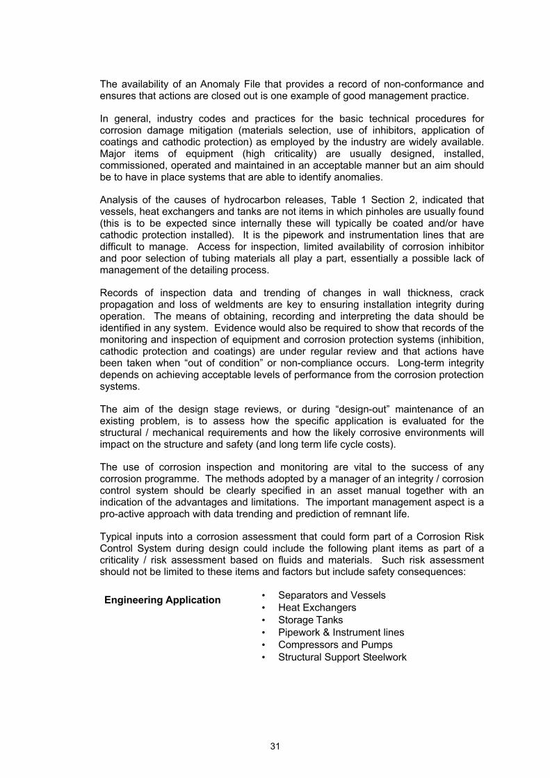
31
The availability of an Anomaly File that provides a record of non-conformance and ensures that actions are closed out is one example of good management practice.
In general, industry codes and practices for the basic technical procedures for corrosion damage mitigation (materials selection, use of inhibitors, application of coatings and cathodic protection) as employed by the industry are widely available. Major items of equipment (high criticality) are usually designed, installed, commissioned, operated and maintained in an acceptable manner but an aim should be to have in place systems that are able to identify anomalies.
Analysis of the causes of hydrocarbon releases, Table 1 Section 2, indicated that vessels, heat exchangers and tanks are not items in which pinholes are usually found (this is to be expected since internally these will typically be coated and/or have cathodic protection installed). It is the pipework and instrumentation lines that are difficult to manage. Access for inspection, limited availability of corrosion inhibitor and poor selection of tubing materials all play a part, essentially a possible lack of management of the detailing process.
Records of inspection data and trending of changes in wall thickness, crack propagation and loss of weldments are key to ensuring installation integrity during operation. The means of obtaining, recording and interpreting the data should be identified in any system. Evidence would also be required to show that records of the monitoring and inspection of equipment and corrosion protection systems (inhibition, cathodic protection and coatings) are under regular review and that actions have been taken when “out of condition” or non-compliance occurs. Long-term integrity depends on achieving acceptable levels of performance from the corrosion protection systems.
The aim of the design stage reviews, or during “design-out” maintenance of an existing problem, is to assess how the specific application is evaluated for the structural / mechanical requirements and how the likely corrosive environments will impact on the structure and safety (and long term life cycle costs).
The use of corrosion inspection and monitoring are vital to the success of any corrosion programme. The methods adopted by a manager of an integrity / corrosion control system should be clearly specified in an asset manual together with an indication of the advantages and limitations. The important management aspect is a pro-active approach with data trending and prediction of remnant life.
Typical inputs into a corrosion assessment that could form part of a Corrosion Risk Control System during design could include the following plant items as part of a criticality / risk assessment based on fluids and materials. Such risk assessment should not be limited to these items and factors but include safety consequences:
Engineering Application • Separators and Vessels • Heat Exchangers • Storage Tanks • Pipework & Instrument lines • Compressors and Pumps • Structural Support Steelwork

32
Fluid Corrosivity • Internal: • Brine phase pCO2, pH2S, pH, Cl-, SO4
= • Oil / Gas / Condensate - water content • External: • Seawater, marine atmosphere
Constructional Materials • C-steel (structural supports) • C-MN steels (vessels and pipework) • Cr-steels & CRAs – (critical items in process
equipment particularly with high H2S levels) stainless steels (austenitic, duplex / ferritic), Ni alloys (Inconel, Incalloy), Cr alloys (Hastalloy)
4.2 LEGISLATION
4.2.1 General
Document should include a list of all current and relevant regulations and guidance as to how these should be incorporated, which at present would include:-
1. Management of Health and Safety at Work Regulations 1992.
2. The Offshore Installations (Safety Case) Regulations 1992, (SCR).
3. Offshore Installations and Wells (Design and Construction) Regulations 1996, (DCR)
4. The Offshore Installations (Prevention of Fire and Explosion, and Emergency Response) Regulations 1995, (PFEER).
5. The Reporting of Injuries, Diseases and Dangerous Occurrences Regulations 1995 (RIDDOR).
6. Pipeline Safety Regulations (PSR) 1966, see also A Guide to the Pipeline Safety Regulations 1966
4.2.2 The Safety Case.
The guidelines should identify the safety case as the key start point for procedures that are considered to impact on safety-critical items and require auditing. Corrosion concerns to be listed for checking could include materials of construction, corrosion control methods and access for inspection and monitoring.
Methods of conducting corrosion inspections and corrosion monitoring could be identified and the means of trending the obtained data together with prediction of future performance should be assessed.
Assessments of conformance, non-conformance and action plans should be conducted by inspectors.

33
4.2.3 Design and Construction
Guidelines should identify the methodology for assessment of procedures that ensure integrity. Review procedures employed during verification should be transparent and the results should be made available to inspectors.
The guidelines should develop a generic approach to ensuring integrity of items in the context of corrosion damage and failure modes linked to corrosion control options, but in terms of:
• Lifecycle: • Design: • Duties: • Operation: • Maintenance: • Reporting: • Decommissioning & Dismantlement:
Key features of a verification scheme should include:
• Independent & Competent Persons • Communications • Safety Critical Elements • Consultation • Reservations • Frequency • Revision • Records • Management
Details would be agreed during Phase 2.
4.2.4 Inherent Safety
In addition to the specific legislative requirements, the guidelines should encourage control of risks using the concept of inherent safety.
4.3 ORGANISATIONAL ARRANGEMENTS
4.3.1 Duty Holder Arrangements.
As part of the documentation recommendations relating to Duty Holder Arrangements should be given. However, these will normally be determined by business objectives and will not parallel the regulatory requirements. Guidance into the overall format for reporting organisational arrangements should be included. These would require that the responsibilities, plans and procedures required to obtain the necessary information to evaluate the management of integrity are clearly identified.

34
4.3.2 Risk Control Systems (RCS)
Management of installation integrity will involve various parts of a duty holder's organisation and specialist organisations (internal consultants and external contractors) to support delivery in their areas of responsibility. The organisation can be considered as a series of layers, each with its own responsibilities and objectives. Each group should be a self-contained RCS reflecting its allocated responsibility for risk.
An outline for the three stages (input, process and output) would be:
a. Design and Construction Phase
Input Process Output
Senior management involvement
Define the Corporate Safety (Integrity & Corrosion?) Policies
Produce written company statements
Middle Management Use appropriate strategies & systems
Ensure structural integrity
Specialists and Contractors (Corrosion Engineers, Inspection and Materials
Development and use of systems for Operations & Maintenance (routine and non-routine), Safety, Corrosion, Inspection and Quality Assurance & Control, Verification and audit of systems, Review of performance
Control of all activities related to corrosion safe operation & maintenance and hydrocarbon releases
Safety & verification {to be agreed} {to be agreed}
Hazard analysis and risk assessment
{to be agreed} {to be agreed}
Information, Records & Database systems
{to be agreed} {to be agreed}
b. Operation and Maintenance Phase
Input Process Output
Senior management involvement
Define the Corporate Safety (Integrity & Corrosion ?) Policies
Produce written company statements
Middle Management Use appropriate strategies & systems
Ensure structural integrity
Specialists, Support Units, and Contractors (Corrosion Engineers, Inspection and Materials Specialists) including Management of contractors
Development and use of systems for Operations & Maintenance (routine and non-routine), Safety, Corrosion, Inspection and Lab. Analysis, Verification and audit of systems, Review of performance including Emergency response, Asset integrity and Corrosion management
Control of all activities related to corrosion safe operation & maintenance and hydrocarbon releases
Safety verification systems {to be agreed} {to be agreed}
Systems for operations & management of change
{to be agreed} {to be agreed}

35
Maintenance & inspection systems
{to be agreed} {to be agreed}
Corrosion management systems
{to be agreed} {to be agreed}
Hazard analysis and risk assessment
{to be agreed} {to be agreed}
Accident and incident investigation
{to be agreed} {to be agreed}
Information, Records & Database systems
{to be agreed} {to be agreed}
Personnel and training ? {to be agreed} {to be agreed}
The guidance notes should identify key actions each with a 'self-contained' risk control system (RCS) in place. The complexity should be proportionate to the particular hazards and risks.
Associated management processes are:
1. Hazard identification.
2. Risk assessment.
3. Risk control – eliminate risks, combat risks at source by engineering controls, minimise risk through suitable systems.
4.3.3 Steps for Basic Safety Management
Recommendations provided and developed during the Phase 2 project will be incorporated to identify the steps in the development of the policy or strategy adopted by the duty holder, for example this would cover.
a. Policy / Strategy
Inputs are the review of the operating systems and the influence of external factors.
Questions to ask to minimise risks are typically:
i. Is there a clear company policy for health & safety issues that also includes those that arise from corrosion hazards? Is there a corporate corrosion policy?
ii. Are the results of safety risk assessments clearly stated and readily available to staff and inspectors?
iii. Is there an obvious policy on corrosion mitigation objectives for the asset? Have the various areas or zones of the facility with different corrosion processes and corrosion rates been identified and corrosion mitigation procedures introduced? Are the required and stated objectives being achieved?
iv. Has provision been made in the corrosion management procedures to allow for changes in composition of the fluids with time or changes in operating conditions?

36
Typical Corporate level Policies Ø No leaks or emissions
Ø Corrosion safe facilities
Ø Zero tolerance corrosion
Ø ?
Policies at an installation level Ø Provision of breathing apparatus protection to operators in facilities with high levels of hydrogen sulphide
Ø Criticality & corrosion audits
Ø Use of condition based strategies for maintenance and repair
Ø ?
Policies at a technical level Ø Audits of inhibitors and chemical vendors
Ø Use of corrosion monitoring
Ø Application of risk based inspection
Ø Data trending with alert / warning levels
Ø ?
b. Organising
In some systems the company strategy will determine the input of roles and responsibilities.
Typical check questions for inspectors would be:
(i) Can specific people with allocated responsibilities be easily identified – are they clear about their accountability?
(ii) Are staff adequately trained and are they and their representatives consulted effectively?
(iii) Have employees and contractors sufficient information about the risks they are exposed to and preventative measures available?
c. Planning and Implementation
Pertinent questions to ensure input into the required process are:
(i) Are integrated plans in place for health & safety, asset integrity environmental concerns, corrosion control, monitoring and inspection?
(ii) Have corrosion hazards and associated risks been identified?
(iii) Have performance criteria been agreed?
(iv) Are plans in place to deal with contingencies? Process deviations? Leaks and emissions? Operation without inhibitors / biocides, and for how long? Corrosion of fire mains? Clogging of nozzles and spray heads?

37
d. Measuring Performance
Questions that could ensure adequate output from the process:
i. How well does the installation perform with regard to health, safety and corrosion issues compared to others?
ii. Are all objectives and criteria being met?
iii. Do investigations of incidents, accidents and failures find all underlying causes?
e. Reviewing Performance
Pertinent questions:
i. Are there areas where guidelines, codes and criteria are inadequate or absent?
ii. Are objectives achieved within acceptable time frames?
iii. Do reviews involve staff at various levels?
iv. How frequently are reviews carried out? By what criteria?
f. Auditing
Questions to assess input, the audit process and output-:
i. Who conducts the audit?
ii. How frequent is the audit?
iii. What changes have been initiated following recent audits?

38
5 DISCUSSION AND CONCLUSIONS
The initial pilot study, as outlined in this draft report, addressed three main areas:
1. The background to an integrated approach for successful safety, asset integrity and corrosion management (Section 2)
2. A survey of the views of corrosion management specialists employed by offshore operators and contractors (Section 3)
3. An outline for the drafting of guidelines relating to corrosion risk assessment and safety management of offshore processing facilities (Section 4)
5.1 PHASE 2 PROJECT
A major objective was to assess the requirements and support for a future HSE guidance report. In this context the specialist contractors welcomed the concept since it would provide a focus for industry practice. Operators, including those not visited, expressed a willingness to participate in open discussions on this subject area. There appears to be, therefore, sufficient support for a Phase 2 project with input from the industry provided the aims of the document and project workscope were suitably defined.
The development to the proposed Phase 2 report must take into account background to the significant changes within the offshore industry over the past few years, as a result of post-Cullen regulations. These requirements have stimulated improvements in corrosion management in many areas and are leading to recognisable benefits in control of problems. This situation could be further improved by the Phase 2 programme.
The goal setting legislation enabled duty holders to adopt less prescriptive but better integrated, and more in-depth, management approaches to safety issues. Previously much reliance was placed by operators on surveyor’s reports from certifying authorities, even infrequent ultrasonic wall thickness measurements were considered by some to constitute corrosion monitoring and be sufficient to comply with SI 289 [19]
. There is now an increasing appreciation of corrosion and safety risks, hence all aspects of corrosion control, including inspection, have to be managed, and seen to be managed, in a more flexible but proactive manner that ensures installation integrity and safety. For example, control of microbiological activity to prevent local through-wall pitting can be of equal importance to safety management as trending the general metal wastage rate in a line. Management of corrosion, integrity and related safety issues is not just “fitness for purpose” and risk based inspection, it involves the overall approach as outlined in Section 2.6 and the audit / verification system required by the legislation.
Acceptance that corrosion related failures in installations essentially result from inadequate management, poor systems and human error would assist greatly in continuing development of corrosion safe management strategies and procedures. It is these management and audit aspects, as well as associated technical considerations, that should be addressed in the development of guidance
[19] Offshore Installations (Construction and Survey) Regulations 1974:Statutory Instrument 1974 / 289
39
documentation. The aim would be provide a bench mark guidance for the UK offshore industry.
5.2 CORROSION AND CORROSION CONTROL MANAGEMENT IN THE OIL & GAS PRODUCTION INDUSTRY
Corrosion management covers a number of interrelated and complex issues in what are still developing subject areas. The inclusion of corrosion and corrosion control, including basic corrosion management aspects into the proposed Phase 2 document would distract from the import requirements of that report. A further report on Corrosion and Corrosion Control Management in the Oil & Gas Production Industry is therefore also proposed. These two reports would compliment each other in content.
Details for the workscope and content for the second report are given in Appendix A.
As well as the two HSE guidance reports on corrosion and corrosion management the following two booklets should also be developed to complete the proposed information package.
5.3 CORROSION RISK ASSESSMENT – INDUSTRIAL CASE STUDIES
The development of a booklet on corrosion risk assessment case studies was not part of the workscope for the current project, but the advantages of such a publication to complement the proposed guidelines for offshore installations should be considered by HSE. Such a document should be for oil / gas processing, pipelines, refineries and chemical plant. Such plant have similar corrosion hazards and risks and are managed in a similar manner.
The contents should include plant and equipment from:
• Oil / gas production – wells, flowlines and manifolds, separation plant, pipelines
• Refineries – storage tanks, cat crackers, distillation columns,
• Chemical plant – reactors, pressure vessels, heat exchangers, pipework
The objective would be to identify good practice, and the results of poor practice, with a view of demonstrating how properly applied corrosion management can improve asset integrity and safety.
The aim is a HS(G) booklet of approximately 30 pages in length similar to the 5 steps to risk assessment. The case studies should be from the design, construction and operation phases of projects.
5.4 BASIC HEALTH & SAFETY MANAGEMENT AND VERIFICATION FOR OFFSHORE PROCESSING
Consideration should be given to the development of HSE INDG 10 page general purpose and overview leaflet
Most companies have high level leaflet on company policies for health and safety risks and environmental risks but these are not necessarily focused on integrity and hydrocarbon releases and prevention by corrosion and maintenance management.

40
6. RECOMMENDATIONS
The development of a comprehensive pack is proposed, which would include, but not be limited to:
1. Guidelines on Corrosion Management and Risk Assessment for Offshore Processing Facilities
2. Management of Oil Industry Corrosion
3. Corrosion Risk Assessment – Industrial Case Studies
4. Health & Safety Verification and Corrosion Management for Offshore Processing
41
APPENDIX A CORROSION AND CORROSION CONTROL MANAGEMENT IN THE OIL & GAS PRODUCTION INDUSTRY
BACKGROUND
Managers and HSE Inspectors need to appreciate how the corrosion engineering controls used by the industry are implemented and evaluated. A high level document should be developed as an aid to those personnel who are not familiar with specialist corrosion areas. Ideally this should be linked to a basic description of separation plant and processing equipment, wells and pipelines.
INTRODUCTION
The aim would be to indicate how the corrosion processes that lead to corrosion damage and failure modes can be seen in the context of the design (materials and mechanical requirements) and operational procedures (chemical treating for improvement of oil / gas separation processes as well as corrosion inhibition and biocide injections).
a. Corrosion Awareness
A background to the causes of corrosion of offshore installations should be provided. An important aspect would be concise descriptions of the terminology used to describe corrosion damage phenomenon and the basic corrosion control methods. An overview of the basis of such a corrosion and corrosion control document is outlined below.
b. Corrosion Concerns
Corrosion, defied as the material reaction with an environment. In practice the engineering application must also be considered since relatively minor changes in parameters can result in significant corrosion damage.
In an offshore installation this normally implies:
1. metallic materials (C-Mn steels, corrosion resistant alloys - CRAs)
2. corrosive environments, internal - acidic solutions (CO2 / H2S dissolved in the produced brines or condensed water) or - external - dissolved oxygen (in sea water or condensed water under thermal insulation).
3. engineering application - the stresses both applied and residual, heat transfer / wall temperatures and the fluid flow conditions.
Assessment of corrosion damage usually indicates that one or more of these factors was not as anticipated in the original design or specification, hence the need to continuously review and audit processing systems throughout the life cycle (management for change):
• Corrosive environments (often more aggressive than anticipated, increased water cuts, souring of the reservoir, mixed fluids from different fields)
• Inadequate materials selection (a lack of quality control procedures, poor post fabrication inspection of welds, sigma phase in CRA weldments)
42
• Poor engineering (the design detailing usually neglects local factors, dead legs, erosion, scaling on heat exchanger surfaces)
Defining the corrosion process is the first step in assessing risk and developing a corrosion control programme. These should be linked to specific items of equipment (e.g. vessels, lines, instrument tubing, etc).
A1 CORROSION PROCESSES
“Sweet” reservoirs contain only carbon dioxide or traces of hydrogen sulphide.
“Sour” reservoirs contain hydrogen sulphide (>100 ppm) and carbon dioxide.
A1.1 “Sweet” Corrosion
The report include a simple introduction to basic corrosion processes and recent developments in scientific understanding of mechanisms.
a. Sweet – CO2 corrosion
This is the result of reaction of carbonic acid with the C-Mn steel equipment to produce a semi-protective iron carbonate scale and hydrogen gas:
Fe + H2CO3 ⇒ FeCO3 + H2
b. Mechanisms and film formation
Document to include a brief description of the process by which carbon dioxide dissolves in the aqueous phase to form an acidic solution, pH typically between 3 and 5. The corrosion rate is essentially determined by the partial pressure of the CO2 and the temperature. Iron carbonate corrosion product films form a non-conductive barrier but with pores between scale crystals that allow ingress of fluid. The scales will also locally fracture and spall due to compressive forces produced as film growth occurs due to the corrosion process.
c. Corrosion predictions
An appreciation of how corrosion predictions are used by the industry for CO2 containing environments. These are typically based on the original work of de Waard and Milliams [20, 21, 22, 23 & 24], however such predictions from laboratory data even when modified by field experience of pipelines are for non-erosive conditions. This approach has been up-dated by Norwegian workers using more comprehensive
[20] C. de Waard and D Milliams 1st Int.Conf. On Internal and External Protection of Pipelines, Paper F1, 1995.
[21] C. de Waard and D. Milliams, Corr., 31, 177, (1975)
[22] C. de Waard, U. Lotz and D. Milliams, Corr., 47, 976, (1991)
[23] C. de Waard and U. Lotz, Paper No. 69, CORROSION’93, Pub. NACE, 1993
[24] C. de Waard, U. Lotz and A. Dugstad, Paper No. 128, CORROSION’95, Pub. NACE, 1995.
43
laboratory data and this now forms the basis of a Norsok standard [25]. Some workers question the validity of this approach, particularly for systems that contain acetates.
Inspectors should appreciate the limitations of the data employed by designers and should ensure that produced fluids are also assessed for the presence of acetates since these can give rise to the accumulation of acetic acid under the carbonate scale which then leads to high rates of corrosion.
Inspectors should check that operators are advised to confirm that the actual field corrosion rates experienced by their plant during early operational life are as predicted in the design basis. This is particularly important for low water cuts or when inhibitors are employed since the performance of inhibited steel may, in practice, not be as predicted in laboratory trials initially employed to select the particular package.
d. Flow effects - ”Mesa-corrosion” / erosion corrosion
Recent understanding of flow enhanced corrosion shows that the adherence of the film and protection afforded to the steel substrate depends on crystal size of the iron carbonate scales. These in turn depends on the specific local corrosive conditions and particularly the flow conditions, as well as the composition and metallurgical condition of the steel. Erosion effects may also occur due to entrained sand impinging on the walls of pipes.
The crystalline size of the iron carbonate appears to be a key factor in protection against erosion-corrosion found in high velocity / high turbulence CO2 systems. The rate of metal loss / film adhesion also depends on the presence of corrosion inhibitors and scale treating chemicals. Local loss of the film is difficult to repair due to the high diffusion rates, that typically occurs at bends / elbows and down stream of protrusions and welds.
Inspectors should ascertain whether an operator is able to control of flow assisted corrosion this is achievable by careful selection of an appropriate inhibitor package.
e. Weld Corrosion
Inspectors should recognise that nickel containing welds exposed to high fluid flow rates and low conductivity fluids are particularly prone to high rates of corrosion. This can give rise to significant loss of weld metal and grooving in condensate lines and process equipment. Corrosion control under these low conductivity conditions can not rely on the normal galvanic sacrificial control afforded by the plate material to the weld metal. Protection can only be achieved by careful selection of an appropriate inhibitor package.
A1.2 “Sour” Corrosion
a. Sour – H2S corrosion
This is the result of dissolved hydrogen sulphide:
[25] NORSOK Standard M-506 “CO2 Corrosion Rate Calculation Model”

44
Fe + H2S ⇒ FeS + H2
Corrosion in H2S containing systems tends to produce more adherent and electronically conductive protective corrosion product films than found in sweet systems. Inspectors should recognise that although the general or uniform corrosion is lower there is also an increased tendency for pitting and cracking of steels.
b. Pitting corrosion
Hydrogen sulphide acts like a corrosion inhibitor in that when present in small amounts (< 100 ppm) in the presence of carbon dioxide it produces a more protective film of iron sulphide than the non-conductive iron carbonate scale. These iron sulphides are more prone to development of deep (through wall) pitting, the local loss of film gives rise to an anodic area surrounded by a large cathodic area of conductive iron sulphide.
c. Cracking Mechanisms
Iron sulphide films also inhibit the formation of molecular hydrogen in the produced fluids. Hence the atomic hydrogen produced by the corrosion reaction diffuses into the steel where it may cause hydrogen damage – hydrogen embrittlement of the steel, hydrogen induced cracking, step wise cracking and stress oriented hydrogen induced cracking. Excessive stress in the steel can also result in sulphide stress cracking.
The document would include details and examples of:
• Hydrogen Damage
• Hydrogen induced cracking
• Stepwise cracking
• SOHIC
• Sulphide stress cracking
d. Fluid compositions and Materials Selection
The importance careful selection of materials for sour service and high temperature fluids with high concentrations of corrodants will addressed. Guidance documents will be referenced, HSE, NACE, EFC. This section would include:
• Corrosion Resistant Alloys
• Environmental Cracking
• Sigma phase attack
A3 EXTERNAL CORROSION
Major concerns that must be considered by in an inspectors evaluation of the corrosion management of an installation

45
a. Marine atmospheres
Offshore pipework and vessels may be exposed to sea spray and suffer accelerated corrosion and pitting. Equipment constructed out of CRAs may not be coated or lagged hence selection of materials to withstand high chloride concentrations would have to be considered. C-Mn steel fabrications would need to be coated.
b. Under insulation (under lagging) corrosion
A major concern through out the process industry is detection and and prevention of accelerated corrosion of carbon steels and CRAs by penetration of rain water, sea spray and wash-down water.
A4 CORROSION CONTROL OPTIONS
Technical aim is to provide cost effective solutions to corrosion problems by selection of appropriate corrosion control options. Options are used singly or in combination, this depends on investment plus operational costs compared to cost benefits (life cycle costs). Inspectors should be aware of the use and limitations of these options as outlined below:
Material Selection
Carbon-Manganese Steels
CRAs (Stainless Steel, Nickel alloys), Clad Steels.
Selection factors include:- strength, weight, degradation processes, ease of fabrication / construction, availability, anticipated life and relative costs.
Coatings External:- marine, atmospheric
Internal:- immersed, acid resistant.
Major factors:- cost, availability, ease of surface prepn. application, inspection, life expectancy.
Resistance to degradation/temperature
Repair options, over-coatability and maintainability.
Chemical Treatments
Inhibition for oil / gas production systems
Use of biocides in water systems, hydrotest & annular fluids
Scale prevention in flowlines & cooling systems
Cathodic Protection
Electrochemical means of corrosion control. Applied to immersed and buried structures, pipelines
Sacrificial & impressed current systems
Environmental Control
Modify moisture/humidity levels, change pH, lower oxygen concentrations
Process Control
Change throughput, flow rate, temperature
Design Improve basic considerations of inherent safety at all design stages including concept and preliminary designs
Use Codes/Specifications during Engineering Design,

46
During detailing phase assess corrosion features:-stress, shape, compatibility, surface condition.
Introduce QA/QC & inspection procedures.
A5 DEVELOPMENT OF A CORROSION CONTROL PROGRAMME
Inspectors should be aware how initial considerations of corrosion concerns can be extended to provide a basic corrosion control programme. This section would include an appreciation of how the design considerations can be evaluated and how the interactions that involve assessment of integrity and safety risks from any selected corrosion control options are constrained by economic risks and benefits. Such considerations should be linked to management requirements of inspection / monitoring. Corrosion Inspection and Monitoring techniques and their limitations will be addressed. Typical techniques are:
CORROSION INSPECTION AND PLANT CONDITION MONITORING TECHNIQUES
Acoustic Emission
Measures the location, initiation and propagation of cracks and defects under stress in metals
Dye Penetrant Simple procedure for locating surface cracks. Requires shut down for internals
Magnetic Particle Surface and subsurface crack and defect location, seams and inclusions
Radiography X-ray and gamma-ray (Co60, Ir192), wall thickness measurement and crack and defect location
Thermography Identifies lack of bond, hot spots, local thinning, temperature changes due to poor/wet lagging
Ultrasonics Indicates internal defects, porosity, lack of fusion, crack location, wall thickness
Visual Examination
Localised corrosion identification, erosion, pitting, deposit scaling and fouling problems, staining and corrosion leakage due to cracking
IN-PLANT MONITORING TECHNIQUES
Weight loss Coupons
Traditional method of limited sensitivity but used in all environments. Type of corrosion observed is an important indicator
Electrical Resistance (ER)
Measures change in probe resistance. Widely used for carbon steel fabrications in gas and liquid phases. Automated readings.
Linear Polarisation Resistance
An electrochemical dc method used for measurement of uniform corrosion. Standard electrochemical technique. Typically requires a conductive electrolyte but some newer probes have a conductive separator between the metal probe elements.
Zero Resistance Ammetry
Established method for assessing galvanic corrosion between dissimilar metals, but can be used with nominally “identical” electrodes in some applications.
Hydrogen Probes Measure rate of diffusion of hydrogen through steels either by means of a pressure gauge or by electrochemical techniques.
Thin Layer Activation
Measures change of radioactivity as a local irradiated area corrodes.

47
Activation
Electrochemical Impedance
An ac method used for general corrosion measurements similar to LPRM. More versatile and accurate than dc measurements.
Electrochemical Noise
A more recent technique used for assessing general corrosion and current and potential fluctuations associated with localised corrosion.
Regular review of data trends and reporting of plant condition then provides management control of asset integrity and performance. A background will be provided to appreciate:
• Data Trending
• IT (Software) Systems
MATERIAL OF CONSTRUCTION
CORROSIVE ENVIRONMENT
ECONOMICS & PROBABILITY OF
SUCCESS
CORROSION CONTROL OPTIONS
CORROSION CONCERNS
CORROSION PROCESSES
CORROSION CONTROL
PROGRAMME
INSPECTION, MANAGEMENT SYSTEM
& MONITORING
CORROSION CONTROL
ENGINEERING CIRCUMSTANCE
Basic Corrosion Control Programme

48
A6 IMPLICATIONS FOR MAINTENANCE
Inspectors should appreciate how corrosion inspection and monitoring as well as corrosion control could also form an integral part of Maintenance Management Strategies.
Typical strategies are:
BREAKDOWN MAINTENANCE
Operate to failure and then repair or replace, often the strategy of last resort but not always cost effective
PREVENTATIVE MAINTENANCE
Simple non-intrusive actions, also known as Planned Maintenance, Fixed time maintenance Run hour maintenance. The deterioration rate needs to known to determine cost effective measurement times.
PREDICTIVE MAINTENANCE
Condition based maintenance uses trend monitoring of deterioration rate to evaluate need for corrective action. Modern maintenance method.
DESIGN-OUT MAINTENANCE
Eliminate the problem
Condition Based Maintenance uses all inspection and monitoring techniques and is advantageous when components are operated close to maximum life before replacement. Continuous monitoring is able to identify random failures resulting from maloperation (opening wrong valve, mechanical damage).
A7 CORROSION MANAGEMENT
An introduction to managing corrosion risks as outlined in Section 2 would be included. In particular this would be focused towards oil production facilities (assets) and would include six functional areas:
Downhole equipment Well casing and liners / completions, tubulars, safety valves, well heads / Xmas trees
Pipelines, flowlines & manifolds
Used to transport produced fluids, separated fluids (oil, gas & condensate), injection water and glycol
Process equipment (topside facilities)
Separation plant and vessels for stabilisation of hydrocarbon fluids, gas plant, removal of brines, sand and sediments
Support equipment Required for ancillary processing, plant for injection water treatment, glycol recovery

49
Structures Offshore platforms
Accessing information sources required for corrosion control will be discussed, since these are often distributed throughout the functional departments of an asset organisation:
• Design and construction information - engineering department
• Production and fluid chemistry - production department and laboratories
• Equipment inspection data - inspection department
• Corrosion monitoring - specialist contractor
• Coatings - maintenance department / contractor
• Cathodic protection - specialist contractor
Suitable technical inclusions for the input can also be found in Guidelines for the Assessment of Corrosion in Process Plant, Offshore Technology Report – OTN 93 246, 1993 and Department of Energy Reports on Offshore Installations: Section 12 on Corrosion Protection. The overall objective is to produce a HSE technical report to complement the Phase 2 guidance report on safety / corrosion management.

50
APPENDIX B INDUSTRY CORROSION SPECIALISTS
CAPCIS wishes to acknowledge the helpful discussions with the following individuals and their organisation’s experience that provided a valuable cross section view of industry practice for input into the review report:
Ian Bradley, OIS Ltd
James Burns, AMEC
Tony Conner / Jamie Harcus, Bureau Veritas.
Bob Harvie, LR
Steve Mc Hattie, Enterprise
Mal Prodger / Kevin Lawson, LRIM
John Ray / Dave Anderson, Elf
Cees de Regt / Alistair Chisolm, DnV
Phil Thompson, Maersk
John Tischuk, Tischuk Enterprises (UK) Ltd
51
APPENDIX C REFERENCE DOCUMENTATION
Management of Health and Safety at Work Regulations 1992.
The Offshore Installations (Safety Case) Regulations 1992
The Offshore Installations and Wells (Design and Construction, etc.) Regulations 1996
The Offshore Installations (Prevention of Fire and Explosion, and Emergency Response) Regulations 1995
The reporting of Injuries, Diseases and Dangerous Occurrences Regulations 1995 (RIDDOR)
“Successful Health and Safety Management”, HS(G) 65, HSE Books 1991, ISBN 0-11-882055-9
Guidelines for the Assessment of Corrosion in Process Plant, Offshore Technology Report – OTN 93 246, 1993
Guidelines on the Assessments of Integrity Management for Offshore Structures During Operation, , Offshore Technology Report – OTX 98 401, 1998
Managing health and safety-Five steps to success - INDG 275 4/98
Five steps to risk assessment INDG163(rev 1) 5/98
R. Patel, “Evaluation of Hydrocarbon Leaks due to Corrosion/erosion in Offshore Process Plant”, A Safety Practical Project, Diploma in Occupational Health and Safety Management, Loughbrough University, 1997

52
APPENDIX D – BACKGROUND ON CORROSION MANAGEMENT
This Appendix contains the following publications that provide an overview on current concepts in corrosion management:
1. R. C. Brouwer, “Corrosion Management in PDO”, Proc. 8th Middle East Corrosion Conference, pp 239 – 244, Bahrain, May 1998, Pub. The Bahrain Soc. Of Engineers & NACE International, 1998.
2. P. A. Attwood, L Fear, J. Graham and A.P. Gifford, “The Application of Risk Based Inspection in Major Oil Field Operations” Proc. Int. Symp. Sept. 1997, Dubai, Pub. NACE International, 1997.
3. D. G. John, P. Attwood and N. Rothwell, “Advances in Integrated Database Systems for Corrosion Management of Oil & Gas Production”, CORROSION’99, Paper No. 249, Pub. NACE International, Houston, 1999.
4. C Googan & V Ashworth, “Pipeline Corrosion Risk Management”, Proc. 8th Middle East Corrosion Conference, pp 623 – 636, Bahrain, May 1998, Pub. The Bahrain Soc. Of Engineers & NACE International, 1998.
5. J. D. Edwards, T. Sydberger and K. J. Mork, “Reliability Based Design of CO2 – Corrosion Control”, CORROSION’96, Paper No. 29, Pub. NACE International, Houston, 1996.

Printed and published by the Health and Safety ExecutiveC0.5 4/01

OTO 1999/064
£15.00 9 780717 620128
ISBN 0-7176-2012-3


![Corrosion Risk Assessment and Safety Management for Offshore Processement Facilities[1]](https://img.pdfslide.us/doc/110x75/55cf99b9550346d0339edb5a/corrosion-risk-assessment-and-safety-management-for-offshore-processement-facilities1.jpg)