Embed Size (px)
Citation preview

LAUNCH MRF-301 A/C Service Station User’s Manual
i
Trademark Information LAUNCH is a registered trademark of LAUNCH TECH. CO., LTD. (short for LAUNCH) in China and other countries. All other LAUNCH trademarks, service marks, domain names, logos, and company names referred to in this manual are either trademarks, registered trademarks, service marks, domain names, logos, company names of or are otherwise the property of LAUNCH or its affiliates. In countries where any of the LAUNCH trademarks, service marks, domain names, logos and company names are not registered, LAUNCH claims other rights associated with unregistered trademarks, service marks, domain names, logos, and company names. Other products or company names referred to in this manual may be trademarks of their respective owners. You may not use any trademark, service mark, domain name, logo, or company name of LAUNCH or any third party without permission from the owner of the applicable trademark, service mark, domain name, logo, or company name. You may contact LAUNCH by visiting Launch at http://www.cnlaunch.com or writing to LAUNCH, Xinyang Building, Bagua 4th Road, Shenzhen, Guangdong Province, P. R. C., to request written permission to use Materials on this manual for purposes or for all other questions relating to this manual.
Copyright Information
Copyright © 2000 by LAUNCH TECH. CO., LTD. All rights reserved. No part of this publication may be reproduced, stored in a retrieval system, or transmitted in any form or by any means, electronic, mechanical, photocopying, recording or otherwise, without the prior written permission of LAUNCH. The information contained herein is designed only for the use of this unit. LAUNCH is not responsible for any use of this information as applied to other units.
Neither LAUNCH nor its affiliates shall be liable to the purchaser of this unit or third parties for damages, losses, costs, or expenses incurred by purchaser or third parties as a result of: accident, misuse, or abuse of this unit, or unauthorized modifications, repairs, or alterations to this unit, or failure to strictly comply with LAUNCH operating and maintenance instructions.
LAUNCH shall not be liable for any damages or problems arising from the use of any options or any consumable products other than those designated as Original LAUNCH Products or LAUNCH Approved Products by LAUNCH.
General Notice
Other product names used herein are for identification purposes only and may be trademarks of their respective owners. LAUNCH disclaims any and all rights in those marks.
LAUNCH MRF-301 A/C Service Station User’s Manual
ii
The equipment is for specialist or qualified technician use only.
Disclaimer All information, illustrations, and specifications contained in this manual are based on the latest information available at the time of publication. Launch reserves all the right to make changes at any time without notice.
Safety Precautions
Read all service procedures and precautions, installation instructions and equipment operating manuals thoroughly. Failure to observe these precautions, or the improper use of equipment, could result in property damage, serious injury or death. Never allow improperly trained personnel to perform these procedures or operate equipment. Read and understand the User’s Manual before
attempting to operate the MRF-301. The unit is only used for the recharging and
recovery of R134a. Do not smoke in proximity to the machine while it is
in operation. Do not use the machine in proximity to sources of
heat and fire. Before performing any operation, check the vehicle
use for the type of refrigerant used by the auto A/C system. Various refrigerants cannot be mixed. After the operation is completed, always close
high-and low-pressure hand valves(H,L) on the side board of the unit, vales for new and used oil bottles. When it is in operation, keep the hoses away from
rotating elements and hot parts such as cooling fans, radiators, etc. Check the oil levels of the new/used oil bottle before
beginning operation. Please dispose the used oil inside used oil bottle according to the environment requirement and keep the used oil bottle empty. A certain concentration of refrigerant may cause
loss of consciousness or death, should prevent the volatile gas from contacting operator’s exposure parts such as skins and eyes. Wear protective gloves and goggles when the machine is in operation. There may be oil fog spray when vacuuming for unit
within started several minutes. Wear protective respirator. Keep away from the children and mental retardation
personnel when performing the unit. The person who operates the unit must be familiar
with the repair and maintenance of A/C system to avoid damaging the equipment and A/C system.
The person who operates the unit must be qualified technician and it is necessary to do operation training before operating the equipment. The unit is an advanced electromechanical product
including precision control components. Never allow operator to make disassembly and service. Only use MRF-301 indoors and in well-ventilated
area. Do not expose it to direct sunlight or rain. The unit should be placed in vertical position and do
not incline or place upside down. Do not contact high-pressure power of the unit and
repair the unit under the power is turned on to avoid electricity shock. Before using the unit for the first time, please do as
follows: open the rear board of the unit and take the fillings around the refrigerant tank and at the bottom of the electronic scale out, and then check if the connection of refrigerant hose is loose; Open the valves on the gas and liquid ports on the tank. Run the function of vacuum for system, and then keep this running state for 5 minutes to check for leaks.
Note: Specifying operations that require attention when operating the equipment.
Warning: Specifying a possible hazard that could result in damage to the machine or personal injury.
LAUNCH MRF-301 A/C Service Station User’s Manual
1
Table Of Content Outline ................................................................. 2 Introduction .......................................................... 2 Primary functions ................................................. 2 Subsidiary functions............................................. 2 Specifications....................................................... 3 Structure .............................................................. 3
1. Main Unit ....................................................... 3 1.1 Control Panel............................................ 4
2. Main Couples ................................................ 6 Operation illustration............................................ 6
1.Preparation..................................................... 7 2.R134a Recovery ............................................ 7 3. Vacuum ......................................................... 7 4.Cooling Oil and Refrigerant Filling ................. 7 5. Recycle ......................................................... 8 6.Auto. Mode..................................................... 8 7. Subsidiary functions ...................................... 9
7.1 System function ........................................ 9 7.2 Component self test................................ 10 7.3 Total used time and times inquiry ........... 10 7.4 Parameter Setting................................... 10 7.5 Adjusting recharging error ...................... 11 7.6 Resuming default value .......................... 11 7.7Calibration of Electronic Scale................. 11
Warning Label.................................................... 12 1.Hazard Warning ........................................... 12 2. Vacuum Pump............................................. 12
Maintenance ...................................................... 12 1.Transportation and Storage of the Unit......... 12 2.Transportation and Storage of Unpacked Unit12 3. Installation Environment .............................. 12 4. Adding Refrigerant (manual adding)............ 12 5. Vulnerable parts list ..................................... 13 6. Vacuum Pump Maintenance........................ 13 7. Drying filter replacement.............................. 14 8. Cleaning filter screen................................... 14 9. Adding new oil to new bottle ........................ 14 10.Empty the Used Oil Bottle .......................... 15
Troubleshooting ................................................. 15 Appendix 1: Main couples.................................. 17

LAUNCH MRF-301 A/C Service Station User’s Manual
2
Outline Different from the general home or commercial air conditioner, the compressor in automotive A/C is semi-closed, and the working surroundings are much more complicated and abominable, such as the factors of high temperature, or contamination of fuel, air and water, jolt vibration, which may cause the leakage and contamination of the auto A/C refrigerant reducing the refrigerant effect. So in summer the refrigerant recharging is the main job for each workshop. But blind recharging may lead to a lot of problems. One wrong operation is to recharge refrigerant directly without vacuuming the A/C system, because the air inside the A/C system cannot be drained out completely and may even cause bad results as bellows: 1) Insufficient refrigerant. Because the air exists inside
the A/C system, one hand it takes some room, on the other hand it causes the pressure inside A/C system and the pressure in refrigerant tank balances, and the recharging can’t be achieved.
2) Redundant air left in A/C system may reduce the A/C power and cooling performance.
Vacuum for A/C system, which not only extract the air but also water. The water mixes into the A/C system easily. But it is very bad for the auto A/C system, even a drop of water may cause pipe block which is so-called “ice block” inside A/C pipes. So the water inside A/C system must be drained completely. During vacuum, the vacuum pump can not only drain the air, but also speed the water volatilizing into vapor with the minus pressure created by draining air, and then suck the water out of the A/C system completely. It is discovered by experts that the time of draining water is 10 times longer than that of draining air. In order to drain the water, it is necessary to possess high limit vacuum and drain performance.
Special attention to the time of vacuuming: Do not stop vacuuming operation immediately after the meter-tank reaches up to the minus pressure. 3~5 minutes more are necessary to achieve the purpose of draining water from A/C system.
Furthermore, why does the refrigerant recovery be required and how can we ensure the recovered refrigerant to be reused? We know that the refrigerant has strong damage to ozonosphere, and finally affect the whole living environment, so international regulations do not allow the refrigerant medium to be drained to atmosphere directly. Meanwhile, as a sort of refrigerant medium, it has an important feature of reliable performance, not decompressing easily, and not chemical-reacted easily with other matters. The nature and performance of the residual refrigerant in A/C system is not changed, but only mixed with some impurities, thus it only requires to be fully filtered, the
regenerative refrigerant as the fresh one can be utilized. MRF-301 is environmental and economic equipment, which has achieved the refrigerant recovery, purge, save, vacuum for A/C and refrigerant recharging. The unit is accepted by more and more workshops and special repair shops.
Introduction
MRF-301 A/C service station has five primary functions such as refrigerant recovery, recharging, vacuum, auto. mode and recycle, meanwhile various subsidiary functions such as parameter setting, alarming note, information inquiry, system function and auto. supply refrigerant, with simple operation, less maintenance and high-efficiency excellent performance.
Primary functions Recovery: To recover and purify the residual refrigerant from the A/C system, and then save the recovered refrigerant. Vacuum: To vacuum for auto A/C system and drain the other gas and vapor inside system completely, and meanwhile benefits the liquid refrigerant recharging. Recharging: To recharge a certain quantity of purified liquid refrigerant into the auto A/C system. Recycle: To recycle the refrigerant saved for a long time inside tank and resume the refrigerant performance; meanwhile increase pressure inside tank and recharging speed. Auto. Mode: After corresponding parameters are well set, the unit could complete the recovery, vacuum, recharging process automatically, saving the operation time.
Subsidiary functions Vacuum leak check: Keep for about 10~15 minutes when the vacuum for system is completed. There is leakage in the system if the pressure increases. Refrigerant measurement: To live display the quantity of refrigerant recharged and recovered. New/used oil exchange: To drain the used cooling oil inside auto A/C system and add new cooling oil to keep the use performance of auto A/C system. Vacuum for system: During the maintenance process of the unit (eg. Replacing the drying filter or filter or refrigerant tank), the air may enter the pipes. At this time, the air needs to be extracted completely through this function. Leak check for nitrogen supply: In order to ensure the sealing of the unit, supply nitrogen for the pipes system after the unit is maintained

LAUNCH MRF-301 A/C Service Station User’s Manual
3
through this function. If the pressure on gauge ‘P’ does not decrease fully indicates that the sealing is good. Component self-test: Check if main components work normally through the function making easy repair and troubleshooting. Information inquiry: To inquire the used time and times of main components and version number of software and hardware making available after-sales service. Parameter setting: User set the related parameters according to the requirements and using habit to achieve the best performance of the unit. Recharge error setting: A small quantity of refrigerant will always remain in pipes when recharging, so the “actual recharging amount” is less than “set recharging amount”. Through setting recharging error, can compensate for pipes lose to ensure there is enough refrigerant in auto A/C system. Resuming default value: To avoid the parameter being set confusedly, user can perform this function to return to the parameters set at the factory to ensure normal use. Calibration of electronic scale: After the refrigerant tank is replaced or the unit is used for a long time, the weight value displayed on electronic scale has a certain difference. Resume the precision of electronic scale through this process.
Refrigerant supply/auto. Supply: When the quantity of refrigerant inside tank is less than a certain amount, refrigerant supply should be performed. User could supply refrigerant through manual supply in the subsidiary functions, or when selecting “Recharging” item, the unit will automatically judge if the refrigerant needs to be supplied. When the quantity of refrigerant is less than 4.5kg, the unit will prompt to supply refrigerant and the amount could be set. After the amount is well set, the unit will supply refrigerant. The supplying will end when the amount reaches up to set amount, or the “Stop” key is pressed.
Specifications
Working environment Ambient temperature: 10~45°C Relative humidity: <90%
Specifications Power supply: □220V±10%~50Hz □110V±10%~60Hz Evacuating air speed of vacuum pump: 4.5CFM Compressor power: 3/8HP Accuracy of electronic scale: 10g Maximum weight of the electronic scale: 30Kg
Drying filter: 500cc, 3/8″ connecting port Capacity of refrigerant tank: 13.6L Maximum working pressure: 17.5bar Maximum recovery speed: 0.5Kg/Min Maximum recharging speed: 2Kg/Min Size: 560x653x1250mm3 Noise: ≤70db Net weight:90kg Gross weight: 110kg
Structure 1. Main Unit
Fig.01
LAUNCH MRF-301 A/C Service Station User’s Manual
4
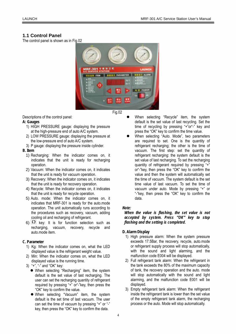
1.1 Control Panel The control panel is shown as in Fig.02
Fig.02
Descriptions of the control panel: A: Gauges
1) HIGH PRESSURE gauge: displaying the pressure at the high-pressure end of auto A/C system.
2) LOW PRESSURE gauge: displaying the pressure at the low-pressure end of auto A/C system.
3) P gauge: displaying the pressure inside cylinder. B. Item
1) Recharging: When the indicator comes on, it indicates that the unit is ready for recharging operation.
2) Vacuum: When the indicator comes on, it indicates that the unit is ready for vacuum operation.
3) Recovery: When the indicator comes on, it indicates that the unit is ready for recovery operation.
4) Recycle: When the indicator comes on, it indicates that the unit is ready for recycle operation.
5) Auto. mode: When the indicator comes on, it indicates that MRF-301 is ready for the auto.mode operation. The unit automatically runs according to the procedures such as recovery, vacuum, adding cooling oil and recharging of refrigerant.
6) key: It is for function selection such as recharging, vacuum, recovery, recycle and auto.mode item.
C. Parameter
1) Kg: When the indicator comes on, what the LED displayed value is the refrigerant weight value.
2) Min: When the indicator comes on, what the LED displayed value is the running time.
3) “+”, “-” and “OK” key: When selecting “Recharging” item, the system default is the set value of last recharging. The user can set the recharging quantity of refrigerant required by pressing “+” or“-”key, then press the “OK” key to confirm the value. When selecting “Vacuum” item, the system default is the set time of last vacuum. The user can set the time of vacuum by pressing “+” or “-” key, then press the “OK” key to confirm the data.
When selecting “Recycle” item, the system default is the set value of last recycling. Set the time of recycling by pressing “+”or“-” key and press the “OK” key to confirm the time value.
When selecting “Auto. Mode”, two parameters are required to set. One is the quantity of refrigerant recharging; the other is the time of vacuum. The first step: set the quantity of refrigerant recharging: the system default is the set value of last recharging. To set the recharging quantity of refrigerant required by pressing “+” or“-”key, then press the “OK” key to confirm the value and then the system will automatically set the time of vacuum. The system default is the set time value of last vacuum. To set the time of vacuum under auto. Mode by pressing “+” or “-”key, then press the “OK” key to confirm the data.
Note:
When the value is flashing, the set value is not accepted by system. Press “OK” key to stop flashing and the setting is completed.
D. Alarm Display
1) High pressure alarm: When the system pressure exceeds 17.5Bar, the recovery, recycle, auto.mode or refrigerant supply process will stop automatically, with the sound and light alarming, and the malfunction code E004 will be displayed.
2) Full refrigerant tank alarm: When the refrigerant in the tank exceeds the 80% of the maximum capacity of tank, the recovery operation and the auto. mode will stop automatically with the sound and light alarming, and the malfunction code E001 will be displayed.
3) Empty refrigerant tank alarm: When the refrigerant inside the refrigerant tank is lower than the set value of the empty refrigerant tank alarm, the recharging process or the auto. Mode will stop automatically.
LAUNCH MRF-301 A/C Service Station User’s Manual
5
with sound and light alarming, and the malfunction code E002 will be displayed.
E. Function keys “Run” key: The system starts to work. “Stop” key: The system stops. “Switch” key: Switch the displays between the recharging quantity of left refrigerant and the current net weight inside refrigerant tank when recharging; Switch the displays between the quantity of recovered refrigerant and net weight inside refrigerant tank when recovering.
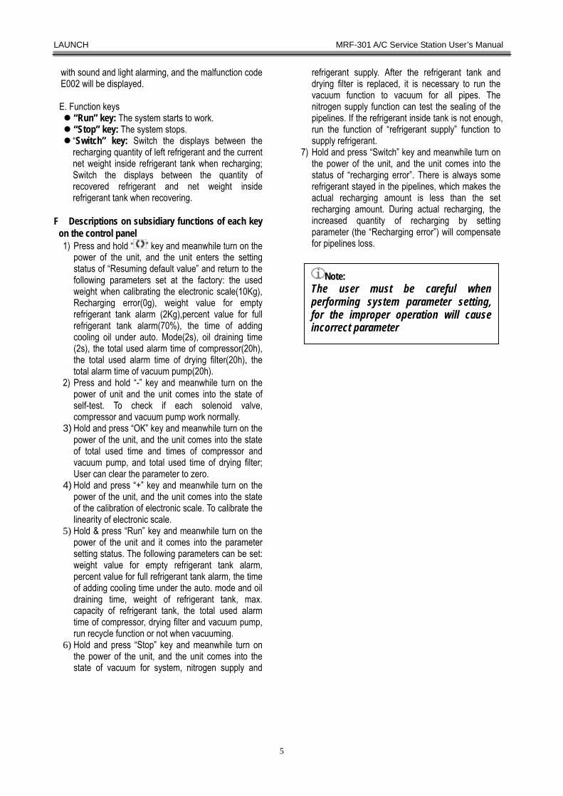
F.Descriptions on subsidiary functions of each key
on the control panel 1) Press and hold “ ” key and meanwhile turn on the
power of the unit, and the unit enters the setting status of “Resuming default value” and return to the following parameters set at the factory: the used weight when calibrating the electronic scale(10Kg), Recharging error(0g), weight value for empty refrigerant tank alarm (2Kg),percent value for full refrigerant tank alarm(70%), the time of adding cooling oil under auto. Mode(2s), oil draining time (2s), the total used alarm time of compressor(20h), the total used alarm time of drying filter(20h), the total alarm time of vacuum pump(20h).
2) Press and hold “-” key and meanwhile turn on the power of unit and the unit comes into the state of self-test. To check if each solenoid valve, compressor and vacuum pump work normally.
3) Hold and press “OK” key and meanwhile turn on the power of the unit, and the unit comes into the state of total used time and times of compressor and vacuum pump, and total used time of drying filter; User can clear the parameter to zero.
4) Hold and press “+” key and meanwhile turn on the power of the unit, and the unit comes into the state of the calibration of electronic scale. To calibrate the linearity of electronic scale.
5) Hold & press “Run” key and meanwhile turn on the power of the unit and it comes into the parameter setting status. The following parameters can be set: weight value for empty refrigerant tank alarm, percent value for full refrigerant tank alarm, the time of adding cooling time under the auto. mode and oil draining time, weight of refrigerant tank, max. capacity of refrigerant tank, the total used alarm time of compressor, drying filter and vacuum pump, run recycle function or not when vacuuming.
6) Hold and press “Stop” key and meanwhile turn on the power of the unit, and the unit comes into the state of vacuum for system, nitrogen supply and
refrigerant supply. After the refrigerant tank and drying filter is replaced, it is necessary to run the vacuum function to vacuum for all pipes. The nitrogen supply function can test the sealing of the pipelines. If the refrigerant inside tank is not enough, run the function of “refrigerant supply” function to supply refrigerant.
7) Hold and press “Switch” key and meanwhile turn on the power of the unit, and the unit comes into the status of “recharging error”. There is always some refrigerant stayed in the pipelines, which makes the actual recharging amount is less than the set recharging amount. During actual recharging, the increased quantity of recharging by setting parameter (the “Recharging error”) will compensate for pipelines loss.
Note: The user must be careful whenperforming system parameter setting,for the improper operation will causeincorrect parameter
LAUNCH MRF-301 A/C Service Station User’s Manual
6
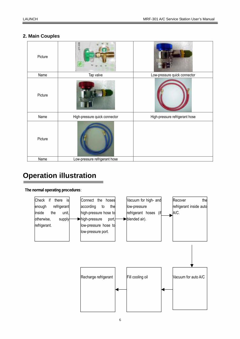
2. Main Couples
Picture
Name Tap valve Low-pressure quick connector
Picture
Name High-pressure quick connector High-pressure refrigerant hose
Picture
Name Low-pressure refrigerant hose
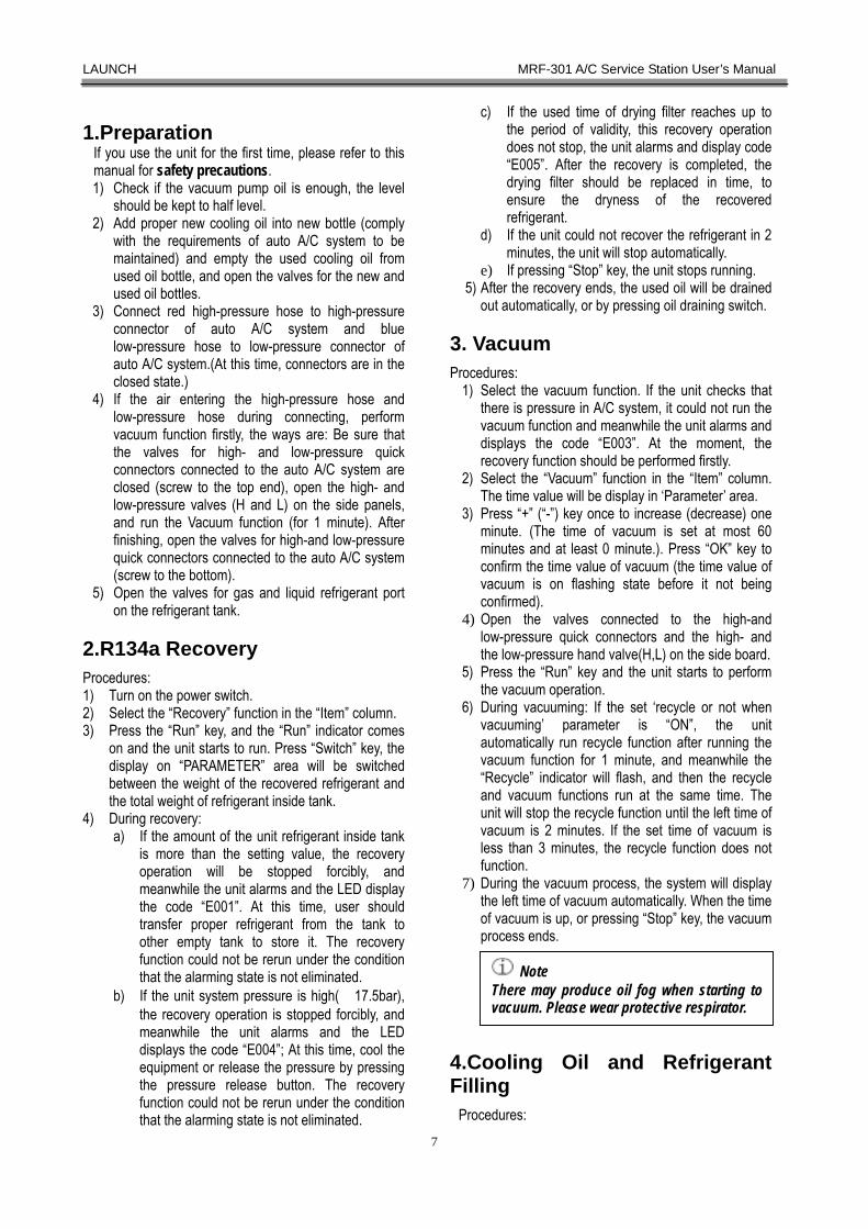
Operation illustration
The normal operating procedures:
Recover therefrigerant inside autoA/C.
Vacuum for auto A/C
Fill cooling oil
Recharge refrigerant
Connect the hosesaccording to thehigh-pressure hose tohigh-pressure port,low-pressure hose tolow-pressure port.
Check if there isenough refrigerantinside the unit,otherwise, supplyrefrigerant.
Vacuum for high- andlow-pressure refrigerant hoses (ifblended air).
LAUNCH MRF-301 A/C Service Station User’s Manual
7
1.Preparation If you use the unit for the first time, please refer to this manual for safety precautions. 1) Check if the vacuum pump oil is enough, the level
should be kept to half level. 2) Add proper new cooling oil into new bottle (comply
with the requirements of auto A/C system to be maintained) and empty the used cooling oil from used oil bottle, and open the valves for the new and used oil bottles.
3) Connect red high-pressure hose to high-pressure connector of auto A/C system and blue low-pressure hose to low-pressure connector of auto A/C system.(At this time, connectors are in the closed state.)
4) If the air entering the high-pressure hose and low-pressure hose during connecting, perform vacuum function firstly, the ways are: Be sure that the valves for high- and low-pressure quick connectors connected to the auto A/C system are closed (screw to the top end), open the high- and low-pressure valves (H and L) on the side panels, and run the Vacuum function (for 1 minute). After finishing, open the valves for high-and low-pressure quick connectors connected to the auto A/C system (screw to the bottom).
5) Open the valves for gas and liquid refrigerant port on the refrigerant tank.
2.R134a Recovery Procedures: 1) Turn on the power switch. 2) Select the “Recovery” function in the “Item” column. 3) Press the “Run” key, and the “Run” indicator comes
on and the unit starts to run. Press “Switch” key, the display on “PARAMETER” area will be switched between the weight of the recovered refrigerant and the total weight of refrigerant inside tank.
4) During recovery: a) If the amount of the unit refrigerant inside tank
is more than the setting value, the recovery operation will be stopped forcibly, and meanwhile the unit alarms and the LED display the code “E001”. At this time, user should transfer proper refrigerant from the tank to other empty tank to store it. The recovery function could not be rerun under the condition that the alarming state is not eliminated.
b) If the unit system pressure is high(≥17.5bar), the recovery operation is stopped forcibly, and meanwhile the unit alarms and the LED displays the code “E004”; At this time, cool the equipment or release the pressure by pressing the pressure release button. The recovery function could not be rerun under the condition that the alarming state is not eliminated.
c) If the used time of drying filter reaches up to the period of validity, this recovery operation does not stop, the unit alarms and display code “E005”. After the recovery is completed, the drying filter should be replaced in time, to ensure the dryness of the recovered refrigerant.
d) If the unit could not recover the refrigerant in 2 minutes, the unit will stop automatically.
e) If pressing “Stop” key, the unit stops running. 5) After the recovery ends, the used oil will be drained
out automatically, or by pressing oil draining switch.
3. Vacuum Procedures:
1) Select the vacuum function. If the unit checks that there is pressure in A/C system, it could not run the vacuum function and meanwhile the unit alarms and displays the code “E003”. At the moment, the recovery function should be performed firstly.
2) Select the “Vacuum” function in the “Item” column. The time value will be display in ‘Parameter’ area.
3) Press “+” (“-”) key once to increase (decrease) one minute. (The time of vacuum is set at most 60 minutes and at least 0 minute.). Press “OK” key to confirm the time value of vacuum (the time value of vacuum is on flashing state before it not being confirmed).
4) Open the valves connected to the high-and low-pressure quick connectors and the high- and the low-pressure hand valve(H,L) on the side board.
5) Press the “Run” key and the unit starts to perform the vacuum operation.
6) During vacuuming: If the set ‘recycle or not when vacuuming’ parameter is “ON”, the unit automatically run recycle function after running the vacuum function for 1 minute, and meanwhile the “Recycle” indicator will flash, and then the recycle and vacuum functions run at the same time. The unit will stop the recycle function until the left time of vacuum is 2 minutes. If the set time of vacuum is less than 3 minutes, the recycle function does not function.
7) During the vacuum process, the system will display the left time of vacuum automatically. When the time of vacuum is up, or pressing “Stop” key, the vacuum process ends.
4.Cooling Oil and Refrigerant Filling
Procedures:
Note: There may produce oil fog when starting tovacuum. Please wear protective respirator.
LAUNCH MRF-301 A/C Service Station User’s Manual
8
1) After the recovery and vacuum process ends, check the quantity of the used oil separated from A/C system and make sure that the quantity of the new oil in the new bottle is 30 ml more than that of used oil. Turn on the switch for new oil adding discontinuously (Note: the high-pressure hand valve should be closed when adding new oil) to make sure that the new oil is sucked into the A/C system until the quantity of the sucked oil is 10ml more than that of the used oil. Close the valve (Note: the oil inside new bottle can not be sucked fully, the level of new oil should be higher than the surface of hose mouth to avoid the air coming into auto A/C system).
2) Select the “Recharging” function in “Item” column. If the weight of the refrigerant inside tank is less than the set weight value for empty refrigerant tank alarm, E002 on ‘Parameter’ area will display for 2 seconds. And meanwhile fill the refrigerant in time.
3) If the amount of the refrigerant inside tank is less than a certain amount, the unit will display “FILL” information indicates that the quantity of the refrigerant inside the tank is not enough and waiting for check if the refrigerant needs to be added.
A. If the “FILL” flashes ten times but it is not confirmed within this period. The unit will enter the state of setting recharging amount.
B. If the “OK” key is pressed, the default supply quantity of refrigerant required will be displayed. Adjust the quantity of refrigerant by pressing “+” and “-” key an press the “OK” key to confirm. Connect the external tank with the enough refrigerant to the fill port on the unit through the hose. Pressing “Run” key starts to fill. The “FILL” and the filled amount of refrigerant will display alternately during filling process, and the filling will stop until the supplied amount of refrigerant reaches up to the set amount or the “Stop” key is pressed.
C. The unit will display the default recharging amount of refrigerant after the filling stops.
4) Set the recharging amount of refrigerant according to the amount of refrigerant desired by vehicle. Press “+” (“-”) key once to increase (decrease) 0.01 Kg (the quantity of recharging is set at least 0.05 Kg). Press “OK” key to confirm the quantity of refrigerant recharging. (The recharging value is on the flashing state before it not being confirmed).
5) Open the high-pressure hand valve(H) and close the low-pressure hand valve(L) on the side board.
6) Press the “Run” key and the recharging begins. The LED displays the recharging quantity of the left refrigerant. Press “Switch” key, the quantity of the left refrigerant recharging and total weight of refrigerant inside tank will be displayed in turn on the “PARAMETER” area. When the recharging speed is
slow or there is a little quantity of refrigerant that can not be recharged into the A/C system, close the high-pressure hand valve(H) and open the low-pressure hand valve(L) on the side board. Start the A/C system to recharge with low pressure sucking way, the recharging operation ends when the display is 0.
7) Close high-and low-pressure hand valves (H and L) on the sideboard, valves for new and used oil bottles.
8) Turn off the power switch and clean up pipes. 9) Turn the transmission screw clockwise under the
electronic scale to ensure that the electronic scale is in protective state.
5. Recycle If the refrigerant inside tank of the unit is stored for a long time, some water and cooling oil may reside into the tank. Perform recycle operation to make the refrigerant recycling in the pipelines and achieve the purpose of regenerative refrigerant through a series purging process of drying, filtering and oil-gas separating. Procedures:
1) Turn on valves for gas port and liquid port on the refrigerant tank.
2) Press “ ” key and select “Recycle” function in ‘ITEM’ area. The time value will be displayed in ‘Parameter’ area.
3) Press “+”(“-”)key once, the recycle time value will “increase”(decrease) one minute, (the recycle time could be set at most 50 minutes, at least 1 minute), press “OK” key to confirm the recycle time value(the recycle time value flashes before it is confirmed).
4) Press the “Run” key and the unit starts to perform the recycle operation, the LED will display the left time; When the displayed value is 0, the recycle process ends, or press “Stop” key to stop the recycle process.
5) During running, if the system pressure is high(≥17.5bar), the recovery operation will be stopped forcibly, and meanwhile the unit alarms and the code E004 will be displayed. It is mainly for the recycle time being too long, cool the unit. The recovery function could not be rerun under the condition that the alarming state is not eliminated.
6.Auto. Mode 1) Open the valves for high-and low-pressure quick
connectors connected to the auto A/C system and
Warning! Do not open high-pressure hand valve (H)when starting the auto A/C system, to avoidthe high pressure entering refrigerant tank.Otherwise, the tank may be broken.
LAUNCH MRF-301 A/C Service Station User’s Manual
9
the high-and low-pressure hand valve (H,L) on the side board, and then open the valves for gas port and liquid port on the refrigerant tank. Open valves for new and used oil bottles.
2) Press “ ”key and select the “Auto. mode” item in “ITEM” column.
3) At this time, “Auto. mode” indicator lights continuously and “Recharging” indicator flashes. The quantity of recharging refrigerant under the “Auto. mode” is displayed on “PARAMETER” area. Set the quantity of refrigerant recharging by pressing “-”or “+” key and press the “OK” key to confirm.
4) After the setting of last step is completed, “Auto. mode” indicator lights continuously and “Vacuum” indicator flashes. The displayed time on ‘PARAMETER’ area is the time of vacuum under the Auto. mode. Press “-” or “+” key to set the time of vacuum and press the “OK” key to confirm.
5) After the setting of last step is completed, only the “Auto. Mode” indicator comes on continuously. Pressing “Run” key starts to run automatically.
6) The first running function is the recovery, at the moment, “Auto. mode” indicator lights continuously, and “Recovery” indicator flashes and “Run” indicator comes on. If there is no refrigerant recovered in 2 minutes, the system will drain the used oil. When the oil draining is completed, the unit comes into the vacuuming function.
7) At the moment, “Auto. mode” indicator lights continuously and “Vacuum” indicator flashes, run the vacuum function. If the set ‘Recycle or not when vacuuming’ parameter is “ON” during vacuuming, vacuum 1 minute and then run the recycle function and the “Recycle” indicator flashes. The recycle and vacuum functions run at the same time. The unit will stop the recycle function automatically until the left time of vacuum is 2 minutes. If the set time of vacuum is less than 3 minutes, the recycle function will not be performed.
8) After the vacuuming ends, the “OIL” will be displayed flickeringly in “Parameter” area. At the moment, close the high-pressure handvalve and open the handvalve on new oil charge bottle on the left panel. Press and hold the charge button to add the oil. Please refer to the Note of adding new oil under auto. Mode.
9) After the oil adding is completed, open the high-pressure handvalve and press “OK” key to run the “Recharging” function automatically. At the moment, the “auto.mode” indicator lights continuously and “Recharging” indicator flashes at the moment. The display in ‘PARAMETER’ area is the left quantity of refrigerant recharging. If the recharge amount does not change in 1 minute continuously, or the recharging operation is completed, the auto. mode function ends and the unit returns to the initial state.
10) During the auto. mode running, it will end so long as pressing “Stop” key, and the unit returns to initial state.
7. Subsidiary functions 7.1 System function The system functions include “Vacuum for system”, “Nitrogen supply” and “Refrigerant supply”. 7.1.1 During the unit being maintained (eg: replace the drying filter, filter, tank inside unit, etc.), The air will enter the system, it is necessary to run “Vacuum for system” function to extract the air inside pipes. 7.1.2 After the unit is maintained, supply pipes with nitrogen by the function of “Nitrogen supply” to ensure the sealing of the unit. If the pressure on the ‘P’ gauge does not decrease fully indicates that the sealing is good. 7.1.3 When the refrigerant inside tank is used up and supplying new refrigerant is required, the “Refrigerant supply” function could be used. Procedures: 1) Close the high-and low-pressure hand valve (H, L)
on the sideboard, valves for gas refrigerant port, liquid refrigerant port on the tank, new and used oil bottles.
2) Hold and press “Stop” key and meanwhile turn on the power switch until the “――――” is displayed on ‘PARAMETER’ area with a sound of ringing, and then loose “Stop” key. At this moment, the unit comes into the “system function” mode.
3) The default item is “Vacuum for system” and the “Vacuum” indicator comes on. The user can press “ ” key to select the function of “Nitrogen supply” (the “Recovery” indicator comes on) or “Refrigerant supply” (the “Auto. mode” indicator comes on).
4) The operation of “Vacuum for system” is same as that of “Vacuum”.
5) Press“ ”key to switch the function of “Nitrogen supply” (“Recovery” indicator illuminates), at the moment, the “Kg” indicator illuminates, the display in ‘Parameter’ area is the total weight on the plate; After pressing “Run” key, supply nitrogen from the high-pressure port or low-pressure port to test the sealing of the unit.
6) Press“ ” key to switch the function of “Refrigerant supply” (“Auto. mode” indicator illuminates), and at the moment the “Kg” indicator illuminates. The display in ‘Parameter’ is default supply amount of refrigerant. The recharge quantity of refrigerant could be set by pressing “+”
Note: When adding oil, it could not be completely suckedby oil sucking pipe. The inlet sucking pipe shouldalways be below the oil level.
LAUNCH MRF-301 A/C Service Station User’s Manual
10
or “-” key, and press “OK” key to confirm the set value. Connect the external tank with the enough refrigerant to the supply port on the unit through the hose, press “OK” key to supply. What the ‘Parameter’ area displayed is the supplied amount. The unit will stop recharging when the recharged amount reaching up to the set value or the “Stop” key is pressed.
7) The user must turn off the power and return on the unit to come into the normal function status.
7.2 Component self test
When doing maintenance for unit, check if the compressor, vacuum pump and solenoid valve work normally through “Self-test” function. Procedures: 1) Press and hold “-” key and meanwhile turn on the
power switch until the “――――” is displayed on “PARAMETER” area with a sound of ringing. Loose the “-” key and the unit comes into the function of “component self-test”.
2) Press“- ”key and “+ ”key, the display in “PARAMETER” area will be displayed among‘V1’ ~ ‘V6’,‘V9’( Vn is for solenoid valve n), ‘C’(for compressor) and ‘P’(for vacuum pump) in turn. Press “OK” key, corresponding component will close after opening for 2 seconds. The operator can hear the sound of action.
3) The user must turn off the power and return on the unit to come into the normal function status.
7.3 Total used time and times inquiry
1) Hold & press “OK” key and meanwhile turn on power switch until the “――――”is displayed on “PARAMETER” area with a sound of ringing. Loose “OK” key and the unit comes into the function of “Total used time and times” of compressor, vacuum pump and drying filter.
2) The default display on panel is the “Total used time” of vacuum pump and the “Recharging” indicator comes on. The user can press “ ” key to select the “Total used times” of vacuum pump (the “Vacuum” indicator comes on), the “Total used time” of compressor (“Recovery” indicator comes on) and “Total used times” of compressor (“Recycle” indicator comes on); the “Total used time” of drying filter (“Auto. mode” indicator comes on).
3) When displaying “Total used time” of vacuum pump, the “Min” indicator will come on and its actual unit is ‘hour’.
4) When displaying “Total used times” of the vacuum
pump, the “Kg” indicator will come on and its actual unit is times.
5) When displaying “Total used time” of compressor, the “Min” indicator will come on and its actual unit is ‘hour’.
6) When displaying “Total used times” of compressor, the “Kg” indicator will come on and its actual unit is times.
7) When displaying “Total used time” of drying filter, the “Min” indicator will come on and its actual time is ‘hour’.
8) Pressing “Switch” key can reset the total used time and times of and compressor and vacuum pump and the total used time of drying filter. Press “Switch” key and a sound will be heard, at this time, 6-digit passwords are required to input. The passwords are input with sound of ringing, and digits of the input passwords are displayed on “PARAMETER” area. The situation will end until the 6-digit passwords are all inputted. If the passwords are correct, the time and times resetting is successful and ‘0’ will be displayed.
9) The user must turn off the power and return on the unit to come into the normal function status.
7.4 Parameter Setting
1) Press & hold “Run” key and turn on the power switch at the same time until the “――――” is displayed on the “PARAMETER” area with a sound of ringing. Loose the “Run” key, the system comes into the function for “Parameter setting”.
2) Set the parameters by pressing “ ” key: weight value for empty refrigerant tank alarm (SET0), percent value of full refrigerant tank alarm (SET1), time of adding cooling oil under auto. mode(SET2), oil draining time(SET3), weight value of empty tank(SET4), max. capacity of tank(SET5), total used alarm time of compressor (SET6), total used alarm time of drying filter(SET7), total used alarm time of vacuum pump(SET8), recycle or not when vacuuming(SET9).
3) When setting the “weight value of empty refrigerant tank alarm”, the “SET0” will be displayed for about 2 seconds and then the set weight value required will be displayed on the “PARAMETER” area, at the moment, “Kg” indicator comes on and its unit is ‘Kg’. Set the weight value by pressing “-”key and “+” key, and then press “OK” key to confirm the value.
4) When setting the “percent value of full refrigerant tank alarm”, the “SET1” will be displayed for about 2 seconds and then the value required will be
Note: When running the function of “componentself-test” and the solenoid valve 7 is open,the operator must be careful with thevacuum pump oil that flying out from the
f th i id
Note: The password is: "-","stop", "+", "run",“OK" and “Switch", the priority ordersof six keys can't be mistaken.

LAUNCH MRF-301 A/C Service Station User’s Manual
11
displayed on the “PARAMETER” area, at the moment, “Min” indicator comes on and its unit is ‘%’. Set the value by pressing “-”key and “+” key, and then press “OK” key to confirm the value.
5) When setting the “time of adding cooling time under auto. mode”, the “SET2” will be displayed for about 2 seconds and then the value required will be displayed on the “PARAMETER” area, at the moment, “Min” indicator comes on and its unit is ‘second’. Set the time value by pressing “-”key and “+” key, and then press “OK” key to confirm the value.
6) When setting the “oil draining time”, the “SET3” will be displayed for about 2 seconds and then the value required will be displayed on the “PARAMETER” area, at the moment, “Min” indicator comes on and its unit is ‘second’. Set the time value by pressing “-”key and “+” key, and then press “OK” key to confirm the value.
7) When setting the “weight value of empty tank”, the “SET 4” will be displayed on ‘Parameter’ area for about 2 seconds, and later the desired set value will be displayed. At the moment, “Kg” indicator comes on and its unit is ‘Kg’. Set the value by pressing “-”key and “+” key, and then press “OK” key to confirm the value.
8) When setting the “Max. capacity of tank”, the “SET 5” will be displayed on ‘Parameter’ area for about 2 seconds, and later the value required will be displayed. At the moment, “Kg” indicator comes on and its unit is ‘Kg’. Set the time value by pressing “-”key and “+” key, and then press “OK” key to confirm the value.
9) When setting “total used alarm time” of compressor, the “SET 6” will be displayed for about 2 seconds and then the value required will be displayed on the “PARAMETER” area, at the moment, “Min” indicator comes on and its unit is ‘hour’. Set the time value by pressing “-”key and “+” key, and then press “OK” key to confirm the data.
10) When setting the “total used alarm time” of drying filter, the “SET 7” will be displayed for about 2 seconds and then the time value required will be displayed on the “PARAMETER” area, at the moment, “Min” indicator comes on and its unit is ‘hour’. Set the time value by pressing “-”key and “+” key, and then press “OK” key to confirm the data.
11) When setting the parameter of “total used alarm time” of vacuum pump, the “SET 8” will be displayed for about 2 seconds and then the time value required will be displayed on the “PARAMETER” area, at the moment, “Min” indicator comes on and its unit is ‘hour’. Set the time value by pressing “-”key and “+” key, and then press “OK” key to confirm the data.
12) When setting the “run recycle function or not when
vacuuming”, the “SET 9” will be displayed for about 2 seconds and then the “ON” or “OFF” will be displayed on the “PARAMETER” area, at the moment, “Min” indicator comes on. Set the parameter(“ON” indicating run recycle when vacuuming, “OFF” indicates: do not run recycle) by pressing “-”key and “+” key, and then press “OK” key to confirm it.
13) The user must turn off the power and return on the unit to come into the normal function status.
7.5 Adjusting recharging error Procedure:
1) Hold & press “Switch” key and meanwhile turn on the power switch until the “――――” is displayed on “PARAMEETER” area with a sound of ringing. Loose “Switch” key and the unit comes into the function of “Adjustment recharging error”.
2) Set the recharging error by pressing “-” and “+” key. Press “OK” key to confirm the recharging error.
3) The user must turn off the power and return on the unit to come into the normal function status.
7.6 Resuming default value 1) Hold and press “ ” key and meanwhile turn on the
power switch until the “――――” is displayed on “PARAMEETER” area with a sound of ringing. Loose “ ” key and the unit comes into the function of “Resuming default value”.
2) At this time, all displays on “PARAMEETER” area go out. Press “OK” key, the operation ends with a sound of ringing.
3) The user must turn off the power and return on the unit to come into the normal function status.
7.7Calibration of Electronic Scale
There will be difference between the displayed weight value and actual value arising from the replacement of the refrigerant tank inside the unit or the long time use of the unit, recalibrate the precision of electronic scale, the weight of refrigerant tank and maximum capacity of refrigerant tank with this function. Procedure: 1) Take refrigerant tank away from the plate to ensure
that it is empty, and then clean up plate. 2) Hold & press “+” key and meanwhile turn on the
power switch until the “――――” is displayed on “PARAMEETER” area with a sound of ringing. Loose the “+” key and the unit comes into the
Note: The user must be careful whenperforming system parameter setting,for the improper operation will causeincorrect parameter

LAUNCH MRF-301 A/C Service Station User’s Manual
12
function of “calibration of electronic scale”. 3) Calibrate the weight of empty plate. At this time,
the ‘0’ is displayed in ‘parameter’ area until the “Run” indicator comes on. Press “OK” key to come into next operation.
4) Calibrate the linearity of electronic scale. Place the reference object with10KG ~20KG (eg. Weight) onto the plate and set corresponding weight value by pressing “-”key and “+” key. Press “OK” key until the “Run” indicator flashes. The unit comes into next operation after a sound of ringing. After a sound is heard, the “End” will be displayed on ‘Parameter’ area, the calibration is completed.
5) The user must turn off the power and return on the unit to come into the normal function status.
Warning Label 1.Hazard Warning
2. Vacuum Pump The vacuum pump oil level should be kept near to the centerline.
Maintenance 1.Transportation and Storage of the Unit The unit should be fixed on the special base seat during transportation. It is suggested to lift and transport the unit with hand or forktruck.
1.1 Transportation a) Transport the unit under the state that it has been
installed on base seat and packed with box to avoid acute shock and impact. Firstly pack the unit with the matter similar with plastic tapes, and then place it in box, but should add the filling material (such as foam or sponge, etc.) between the unit and packing box to avoid scratching the outside surface when the unit shakes.
b) Do not allow the maximum incline angel to exceed 45°. Do not place upside down.
1.2 Storage Store only in dryness and well-ventilated area.
2.Transportation and Storage of Unpacked Unit
1) Transport only with hand or soft belt. 2) Not suit for long distance transportation. 3) It should be put in the non-direct sunshine and
well-ventilated area.
3. Installation Environment 1) The distance between the unit and outside wall or
other goods should be kept over 200mm.The unit should be kept in well-ventilated area and its temperature is within -10℃~ +50℃.
2) To ensure operation safety, please confirm that the unit and the power socket are well grounded.
4. Adding Refrigerant (manual adding)
When the refrigerant amount inside tank is less than the set value (it is suggested to keep 5kg or so), adding refrigerant are required. Add refrigerant to tank with the function of “Adding refrigerant” in “System function” the detailed procedure is shown as follows: 1) Open the valves for gas refrigerant port and liquid
refrigerant port on the tank. 2) Connect the supply hose for new refrigerant to the
filling port of the unit and open the bottle valve. 3) Hold & press “Stop” key, and meanwhile turn on
the power of the unit and it comes into the status of “System Function”. Select “Refrigerant supply” function (“Auto.mode” indicator comes on) and press the “Run” key to add refrigerant.
Warning! If an extension cord is necessary, a cordwith a current rating equal to or more thanthat of the equipment should be used.

LAUNCH MRF-301 A/C Service Station User’s Manual
13
5. Vulnerable parts list
No. Name Specifications Number Specifications after replacement
1 Power cables AC250V/10A AC110V/10A 1PCS ≥ original
2 Fuse AC250V/15A AC110V/20A 1PCS same as original
3 High-pressure quickconnector (female) Special for R134a 1PCS same as original
4 Low-pressure quickconnector (female) Special for R134a 1PCS same as original
5 High-pressure refrigerant hose Special for R134a 1PCS Same as original
6 Low-pressure refrigerant hose Special for R134a 1PCS same as original
7 Tap-valve See sample 1PCS same as original 8 Drying filter See sample 1PCS same as original 9 Filter screen See sample 2PCS same as original
6. Vacuum Pump Maintenance
In order to ensure the normal use performance of vacuum pump, supply vacuum pump oil in time with the same type when the vacuum pump oil level is less than the lowest scale. Replace the vacuum pump oil with high quality in time when it becomes turbid or emulsified. 1. Vacuum pump oil supply
A. Open the front panel of the unit and locate the vacuum pump.
B. Unscrew the red oil fill plug on the top of the right side of the vacuum pump (refer to Fig.3).
C. Close the high- and low-pressure hand valves and then run the vacuum function.
D. Check the oil level after vacuuming for 1 minute, if the level is lower than the lowest level of the sight glass, slowly supply the oil with same type into vacuum pump until the level is up to the middle position of sight glass.
E. Screw the oil fill plug tightly and install the front panel to original position.
2. Vacuum pump oil replacing A. Open the front panel of the unit and locate the
vacuum pump. B. Open the handvalve on the side panel and keep
the high- and low- pressure ports opening to atmospheric air.
C. Unscrew the oil drain plug at the bottom of the right side of the vacuum pump (refer to Fig.3) and contain the used oil with proper container.
D. Run the vacuum function to lead the used oil to container until there is no oil flowing out.
E. Screw the oil drain plug tightly. F. Open the oil fill plug and add new vacuum
pump oil with high quality to make the oil level to the middle position of the sight glass.
G. Close high- and low-pressure handvalves and run the vacuum function.
H. Check the oil level after vacuuming for 1 minute, if the level is lower than the sight glass level, slowly supply the oil with same type into vacuum pump until the level is up to the medium position of sight glass.
I. Screw the oil fill plug tightly and install the front panel to original position.
Fig.03
Oil fill
Oil drain plug
LAUNCH MRF-301 A/C Service Station User’s Manual
14
7. Drying filter replacement
Replace it immediately when the unit displays E00F or the color of sight glass becomes pink indicates the defective drying filter to make sure that the recovered refrigerant confront with the use requirement. Note that its specifications of the new drying filter should be same as that of the original one. Purchase the drying filter from the local branch or dealer.
Please wear essential protective goggles and respirator, detailed procedures are shown as bellows:
1) Open the rear panel of the unit, and then close the valves on the vapor and liquid ports (L and V)of the tank,. Run the “Recycle” function for 5~10 minutes, and turn off the power.
2) Close the valves of the vapor and liquid ports of the refrigerant tank.
3) Open the front panel of the unit and locate the drying filter (refer to Fig.4)
4) Loosen the nuts at the ends of the drying filter with two pieces of spanner (note that there is little quantity of gas out in pipe), take down the used drying filter.
5) Install new drying filter with the same specification as the original direction (with the actual arrow), tight the thread well with two pieces of spanners.
6) Perform the operation of vacuum for system and check for leaks.
7) If there is leakage, check and solve it until there is no any leakage, and then install the front panel well.
8) Open the two valves of the refrigerant tank and then install the rear panel.
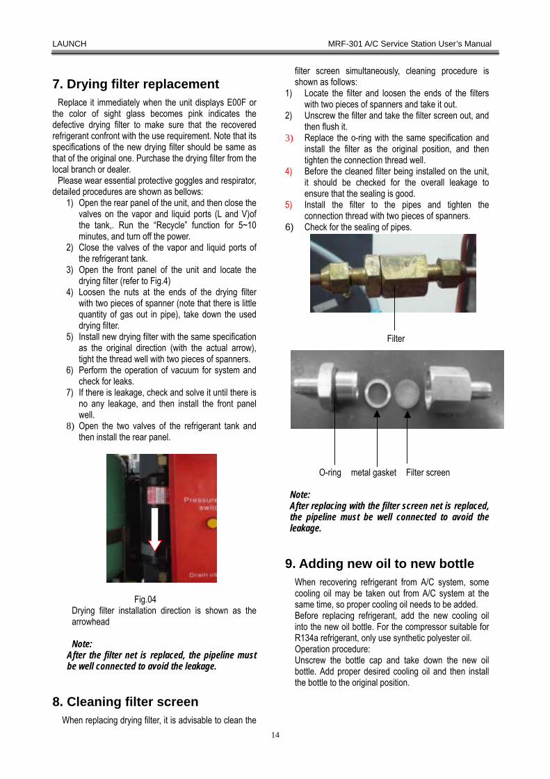
Fig.04
Drying filter installation direction is shown as the arrowhead Note:
After the filter net is replaced, the pipeline must be well connected to avoid the leakage.
8. Cleaning filter screen
When replacing drying filter, it is advisable to clean the
filter screen simultaneously, cleaning procedure is shown as follows:
1) Locate the filter and loosen the ends of the filters with two pieces of spanners and take it out.
2) Unscrew the filter and take the filter screen out, and then flush it.
3) Replace the o-ring with the same specification and install the filter as the original position, and then tighten the connection thread well.
4) Before the cleaned filter being installed on the unit, it should be checked for the overall leakage to ensure that the sealing is good.
5) Install the filter to the pipes and tighten the connection thread with two pieces of spanners.
6) Check for the sealing of pipes.
Filter
O-ring metal gasket Filter screen Note: After replacing with the filter screen net is replaced, the pipeline must be well connected to avoid the leakage.
9. Adding new oil to new bottle When recovering refrigerant from A/C system, some cooling oil may be taken out from A/C system at the same time, so proper cooling oil needs to be added. Before replacing refrigerant, add the new cooling oil into the new oil bottle. For the compressor suitable for R134a refrigerant, only use synthetic polyester oil. Operation procedure: Unscrew the bottle cap and take down the new oil bottle. Add proper desired cooling oil and then install the bottle to the original position.
LAUNCH MRF-301 A/C Service Station User’s Manual
15
10.Empty the Used Oil Bottle Drain used oil to used oil bottle after each recovery is complete, and dispose the used oil properly in time.
Operation procedure: Take the used oil bottle from the position of quick connector. After the used oil is disposed properly, reinstall it well.
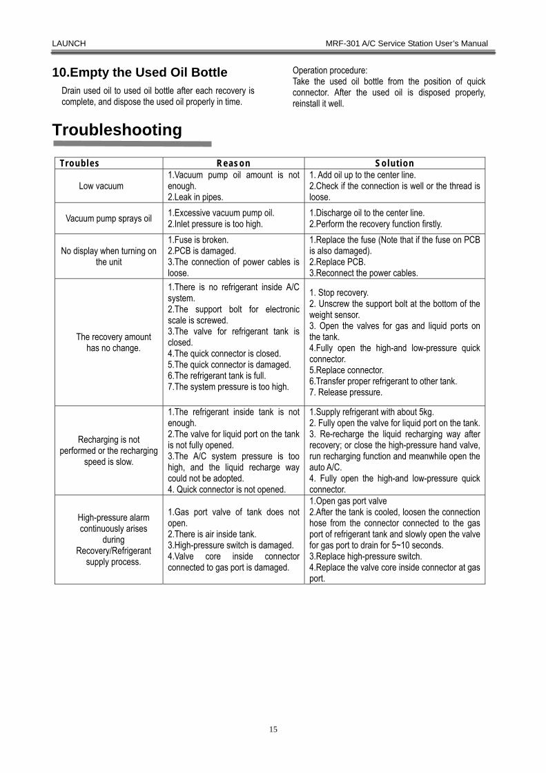
Troubleshooting
Troubles Reason Solut ion
Low vacuum 1.Vacuum pump oil amount is not enough. 2.Leak in pipes.
1. Add oil up to the center line. 2.Check if the connection is well or the thread is loose.
Vacuum pump sprays oil 1.Excessive vacuum pump oil. 2.Inlet pressure is too high.
1.Discharge oil to the center line. 2.Perform the recovery function firstly.
No display when turning on the unit
1.Fuse is broken. 2.PCB is damaged. 3.The connection of power cables is loose.
1.Replace the fuse (Note that if the fuse on PCB is also damaged). 2.Replace PCB. 3.Reconnect the power cables.
The recovery amount has no change.
1.There is no refrigerant inside A/C system. 2.The support bolt for electronic scale is screwed. 3.The valve for refrigerant tank is closed. 4.The quick connector is closed. 5.The quick connector is damaged. 6.The refrigerant tank is full. 7.The system pressure is too high.
1. Stop recovery. 2. Unscrew the support bolt at the bottom of the weight sensor. 3. Open the valves for gas and liquid ports on the tank. 4.Fully open the high-and low-pressure quick connector. 5.Replace connector. 6.Transfer proper refrigerant to other tank. 7. Release pressure.
Recharging is not performed or the recharging
speed is slow.
1.The refrigerant inside tank is not enough. 2.The valve for liquid port on the tank is not fully opened. 3.The A/C system pressure is too high, and the liquid recharge way could not be adopted. 4. Quick connector is not opened.
1.Supply refrigerant with about 5kg. 2. Fully open the valve for liquid port on the tank. 3. Re-recharge the liquid recharging way after recovery; or close the high-pressure hand valve, run recharging function and meanwhile open the auto A/C. 4. Fully open the high-and low-pressure quick connector.
High-pressure alarm continuously arises
during Recovery/Refrigerant
supply process.
1.Gas port valve of tank does not open. 2.There is air inside tank. 3.High-pressure switch is damaged. 4.Valve core inside connector connected to gas port is damaged.
1.Open gas port valve 2.After the tank is cooled, loosen the connection hose from the connector connected to the gas port of refrigerant tank and slowly open the valve for gas port to drain for 5~10 seconds. 3.Replace high-pressure switch. 4.Replace the valve core inside connector at gas port.

LAUNCH MRF-301 A/C Service Station User’s Manual
16
Phenomena Code Meaning and Handing Solution
1. E001- Full tank alarm Phenomena: The unit displays ‘E001’ and the alarming sound will be heard when performing the recovery item and recovery item under auto. Mode. Meaning: The refrigerant inside the tank of the unit is full, the unit could not perform the recovery and auto. Mode function, the functions will stop automatically stop when running the function. Handing solution: Some refrigerant inside tank is required to be transmitted to external tank for storing. Connect the external empty tank to the high-(or low-) pressure ports through hose and open the corresponding handvalve. Close the low-(or high-) pressure handvalve and open the valve of the empty tank. Run the vacuum function for five minutes, and then select recharging function. Set the recharging quantity of refrigerant (5 kg is advisable), and then run the unit. 2.E002- Empty tank alarm Phenomena: The unit displays ‘E002’ and the alarming sound will be heard when performing the recharging item and recharging item under auto. Mode. Meaning: The refrigerant inside tank is not enough and the unit could not perform the recharging function and the recharging function under auto.mode, The unit will stop automatically when the functions be performed. Handing solution: Refrigerant needs to be supplied for the tank of the unit. Connect the external tank with enough refrigerant (more than 5kg is advisable) to the fill port of the unit through hose. Run the refrigerant supply function of system function, refer to the above section. 3. E003-Vacuum is forbidden Phenomena: The unit displays ‘E003’ and the alarming sound will be heard when selecting the vacuum item and vacuum item under auto. Mode. Meaning: There is refrigerant in A/C system or pipes, the unit could not perform the function. Handling solution: After running the recovery function, run vacuum operation again.
4.E004-High-pressure alarm Phenomena: The unit displays ‘E004’ and the alarming sound will be heard when performing the recovery item, recovery item under auto. Mode and recycle item. Meaning: The pressure in pipeline is too high and the unit could not perform these functions, these functions will stop automatically. Handling solution: After the unit is turned off and cooled down, press the pressure relief valve to release the system pressure.
5. E00R- Note for adding compressor cooling oil
Phenomena: The unit displays ‘E00R’ and the alarming sound will be heard when performing the recovery item, recovery item under auto. Mode and recycle item. Meaning: The used time of compressor reaches up or exceeds the maintenance time. Handling solution: check if the cooling fan works normally, if not, supply proper lubricating, and then check if the working performance of compressor is normal, eg. If the extracting speed of the refrigerant when recovering is greatly reduced, supplying compressor lubricating oil is required (through the return port of compressor, it is advisable to operate the operation by professional personnel). Reset the total used time of compressor under the parameter inquiry function. Refer to the above section for resetting.
6. E00VE- Note for adding vacuum pump oil
Phenomena: The unit displays ‘E00V’ and the alarming sound will be heard when performing the vacuum process, vacuum process under auto. Mode. Meaning: The total used time of vacuum pump reaches up to or exceeds maintenance time. Handling solution: Check if the vacuum pump oil is not enough or metamorphic, supply oil or replacing oil, refer the above section for detailed way. Reset the total used time of vacuum pump under parameter inquiry function. Refer to the above section for resetting.
7. E00F-Note for replacing drying filter
Phenomena: The unit displays ‘E00F’ and the alarming sound will be heard. Meaning: The total used time of compressor reaches up or exceeds the replacing time. Handling solution: Replacing the drying filter with same specification immediately, refer to above section for detailed procedure. Reset the total used time of vacuum pump under the parameter inquiry function. Refer to the above section for resetting.
Note: The unit needs to be repaired and maintained byprofessional technician!
Warning! The compressor, vacuum pump, condenser, andsolenoid valve will heat when performing repairand maintenance, always be careful to avoidscalding.

LAUNCH MRF-301 A/C Service Station User’s Manual
17
Appendix 1: Main couples
No. Part Number Part name Picture
1
□102990044 □102990086
Compressor 220V Compressor 110V
2 □103260065 □103260076
Vacuum pump 220v Vacuum pump 110v
3 103260162 Condenser
4
□103150012 □102250004
Fan 220V Fan 110V
5 103260062 Drying filter
6 103260064 Oil separator
7 103260063 Oil separator for heat exchange
8 □102240020 □102240022
Solenoid valve 220V Solenoid valve 110V
9 103160014 One-way valve
10 103170001 Refrigerant tank
11 103160016 Cut-off valve
12 103160019 Tap valve
13
102210049
Switching type power
LAUNCH MRF-301 A/C Service Station User’s Manual
18
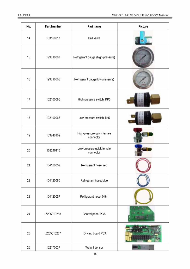
No. Part Number Part name Picture
14 103160017 Ball valve
15 199010007 Refrigerant gauge (high-pressure)
16 199010008 Refrigerant gauge(low-pressure)
17 102100065 High-pressure switch, KP5
18 102100066 Low-pressure switch, kp5
19 103240109 High-pressure quick female connector
20 103240110 Low-pressure quick female connector
21 104120059 Refrigerant hose, red
22 104120060 Refrigerant hose, blue
23 104120057 Refrigerant hose, 0.9m
24 Z205010268 Control panel PCA
25 Z205010267 Driving board PCA
26 102170037 Weight sensor

LAUNCH MRF-301 A/C Service Station User’s Manual
19
No. Part Number Part name Picture
27 □105010452(VDE) □105010453(CCC) □105010454(UL)
Power cables
28 102100096 Button switch (red)
29 102100097 Button switch (green)
30 102100098 Button switch (Yellow)
31 104990006 Oil bottle
32 102100030 Boat switch
33 103160030 Valve for tank

LAUNCH MRF-301 A/C Service Station User’s Manual
Warranty THIS WARRANTY IS EXPRESSLY LIMITED TO PERSONS WHO PURCHASE LAUNCH PRODUCTS FOR PURPOSES OF RESALE OR USE IN THE ORDINARY COURSE OF THE BUYER’S BUSINESS. LAUNCH electronic product is warranted against defects in materials and workmanship for one year (12 months) from date of delivery to the user. This warranty does not cover any part that has been abused, altered, used for a purpose other than for which it was intended, or used in a manner inconsistent with instructions regarding use. The exclusive remedy for any automotive meter found to be defective is repair or replacement, and LAUNCH shall not be liable for any consequential or incidental damages. Final determination of defects shall be made by LAUNCH in accordance with procedures established by LAUNCH. No agent, employee, or representative of LAUNCH has any authority to bind LAUNCH to any affirmation, representation, or warranty concerning LAUNCH automotive meters, except as stated herein.
Disclaimer
THE ABOVE WARRANTY IS IN LIEU OF ANY OTHER WARRANTY, EXPRESSED OR IMPLIED, INCLUDING ANY WARRANTY OF MERCHANTABILITY OR FITNESS FOR A PARTICULAR PURPOSE.
Order Information
Replaceable and optional parts can be ordered directly from your LAUNCH authorized tool supplier. Your order should include the following information: Quantity Part number Item description
Customer Service
If you have any questions on the operation of the unit, please contact us:
Tel: 86-755-82269474, Fax:86-755-82264570, E-mail: [email protected].
If your unit requires repair service, return it to the manufacturer with a copy of the sales receipt and a note describing the problem. If the unit is proved to be in warranty, it will be repaired or replaced at no recharge. If the unit is proved be out of warranty, it will be repaired for a nominal service recharge. Send the unit pre-paid to:
Attn: Overseas Department
LAUNCH TECH. CO., LTD. Xinyang Building, Bagua 4th Road, Shenzhen, Guangdong Province, P.R.China