Embed Size (px)
Citation preview
Safety Instructions and Parts List
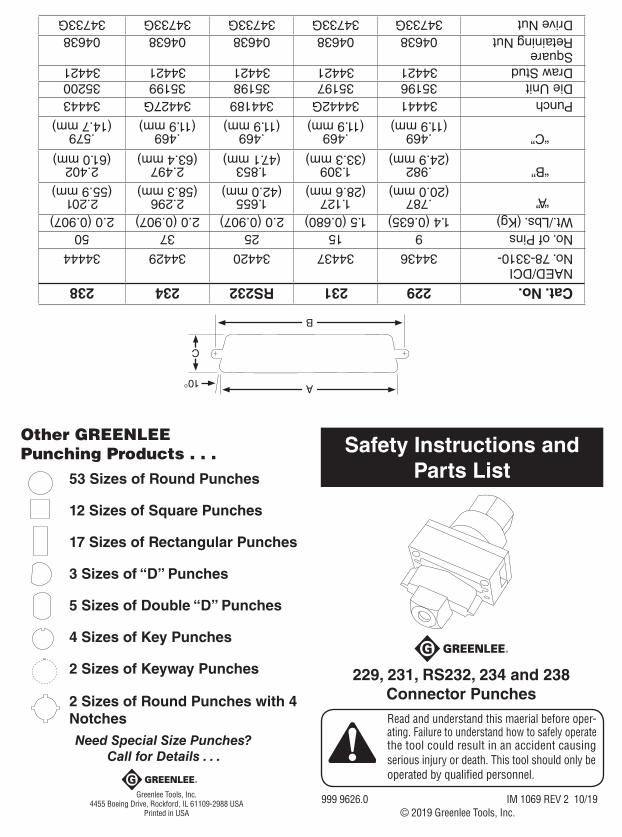
Other GREENLEE Punching Products . . .
53 Sizes of Round Punches
12 Sizes of Square Punches
17 Sizes of Rectangular Punches
3 Sizes of “D” Punches
5 Sizes of Double “D” Punches
4 Sizes of Key Punches
2 Sizes of Keyway Punches
2 Sizes of Round Punches with 4 NotchesNeed Special Size Punches?
Call for Details . . .
229, 231, RS232, 234 and 238Connector PunchesRead and understand this maerial before oper- ating. Failure to understand how to safely operate the tool could result in an accident causing serious injury or death. This tool should only be operated by qualified personnel.
999 9626.0 IM 1069 REV 2 10/19© 2019 Greenlee Tools, Inc.
Greenlee Tools, Inc.4455 Boeing Drive, Rockford, IL 61109-2988 USA
Printed in USA
Cat. No.229231RS232234238NAED/DCI No. 78-3310-3443634437344203442934444
No. of Pins915253750Wt./Lbs. (Kg)1.4 (0.635)1.5 (0.680)2.0 (0.907)2.0 (0.907)2.0 (0.907)
“A”.787 (20.0 mm)
1.127 (28.6 mm)
1.655 (42.0 mm)
2.296 (58.3 mm)
2.201 (55.9 mm)
“B”.982 (24.9 mm)
1.309 (33.3 mm)
1.853 (47.1 mm)
2.497 (63.4 mm)
2.402 (61.0 mm)
“C”.469 (11.9 mm)
.469 (11.9 mm)
.469 (11.9 mm)
.469 (11.9 mm)
.579 (14.7 mm)
Punch3444134442G34418934427G34443Die Unit3519635197351983519935200Draw Stud3442134421344213442134421Square Retaining Nut0463804638046380463804638Drive Nut34733G34733G34733G34733G34733G
A
B
C
10°
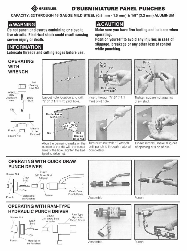
D’SUBMINIATURE PANEL PUNCHESCAPACITY: 22 THROUGH 16 GAUGE MILD STEEL (0.8 mm - 1.5 mm) & 1/8” (3.2 mm) ALUMINUM
Do not punch enclosures containing or close to live circuits. Electrical shock could result causing severe injury or death.
Make sure you have firm footing and balance when operating. Position yourself to avoid any injuries in case of slippage, breakage or any other loss of control while punching.
Lubricate threads and cutting edges before use.INFORMATION
OPERATING WITH WRENCH
OPERATING WITH QUICK DRAW PUNCH DRIVER
OPERATING WITH RAM-TYPE HYDRAULIC PUNCH DRIVER
Layout hole location and drill 7/16” (11.1 mm) pilot hole.
Insert through 7/16” (11.1 mm) pilot hole.
Dissassemble, shake slug out of opening at side of die.
Turn drive nut with 1” wrench until punch is through material completely.
Align the centering marks on the outside of the die with the center lines of the hole. Tighten the ball bearing drive nut.
Tighten square nut against draw stud.
Ball Bearing
Drive Nut
Apply Moly
Lubricant Here
Square Nut
Square Nut
Square Nut
Material to be
Punched
Punch
Punch
Punch
Die
Die
Material to be Punched
Material to be Punched
Draw Stud
Die
Draw Stud
Draw Stud
Quick Draw Punch Driver
Ram Type Hydraulic
Punch Driver
Spacer
33967 3/8” Draw Stud
Adapter
33967 3/8” Draw Stud
Adapter
Assemble
Assemble
Punch
Punch