Embed Size (px)
DESCRIPTION
otdr
Citation preview
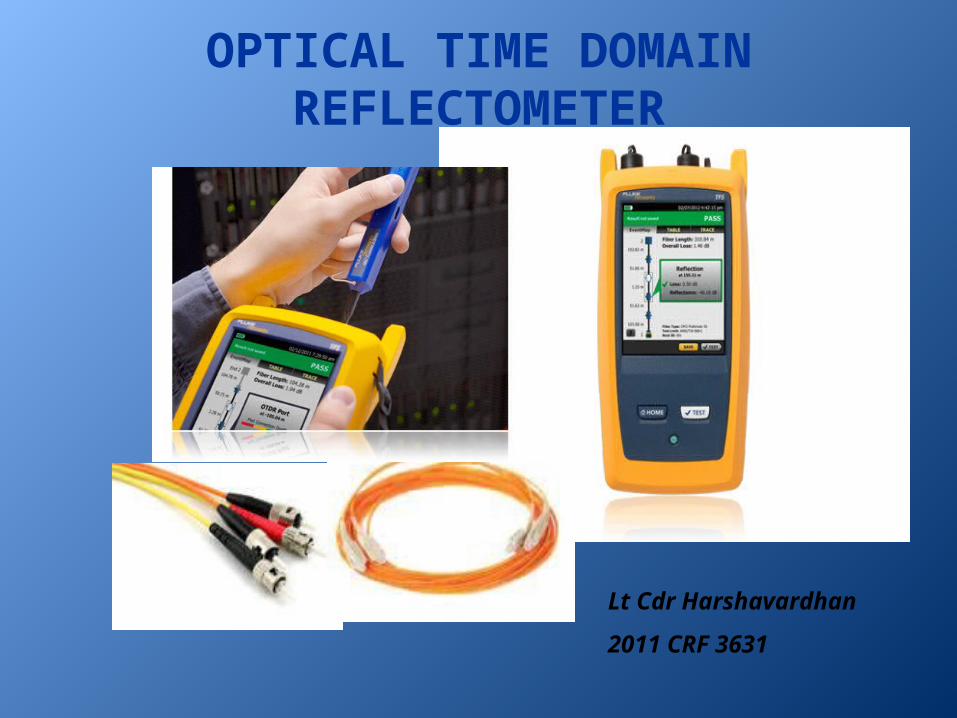
OPTICAL TIME DOMAIN REFLECTOMETER
Lt Cdr Harshavardhan
2011 CRF 3631

CONTENT
• Basic Introduction
• Reflection is the key
• Block diagram
• Evaluation of few traces
• Factors affecting OTDR trace
• Cost analysis
April 17, 2023 Optical Time Domain Reflectometer 2

Optical Time Domain Reflectometer (OTDR)
• A device for characterizing a fiber optic cable • An optical pulse is transmitted through the fiber and the resulting
backscatter and reflections to the input are measured as a function of time
• Useful in estimating attenuation as a function of distance
• Identifying defects and other localized losses
• Check the quality of fiber optic links by measuring backscatter
April 17, 2023 3Optical Time Domain Reflectometer

FRESNEL’S REFLECTION• Light moves from a medium of a refractive index (n1 )into a second medium with
refractive index (n2)
• Both reflection and refraction of the light may occur. • The Fresnel equations describe what fraction of the light is reflected and what
fraction is refracted
n1 sin1 n2 sin2April 17, 2023 4Optical Time Domain Reflectometer
Source-wikipedia

RAYLEIGH BACKSCATTERING
• Result of the elastic collisions between the light wave and the silica molecules in the fiber.
• Accounts for about 96 percent of attenuation in optical fiber
Light scattered in all directions after interaction with silica
some portion of the light propagates forward
deviates out of the propagation path and escapes from the fiber core
reflected back toward the light source
April 17, 2023 5Optical Time Domain Reflectometer

REFLECTION IS THE KEY• Rayleigh backscattering
– used to calculate the level of attenuation in the fiber as a function of distance – Expressed in dB/km– shown by a straight slope in an OTDR trace– Higher wavelengths are less attenuated than shorter ones and thus require less power
to travel over the same distance in a standard fiber
• Fresnel’s reflection– detects physical events along the link. – When the light hits an abrupt change in index of refraction (e.g., from glass to air) a
higher amount of light is reflected back, creating Fresnel reflection– thousands of times bigger than the Rayleigh backscattering. – Fresnel reflection is identifiable by the spikes in an OTDR trace – Reflections from connectors, mechanical splices, fiber breaks
April 17, 2023 6Optical Time Domain Reflectometer

HOW OTDR WORKS
• An OTDR calculates the distances to Events by measuring the time elapsed between transmission of the light and reception of the reflection
• The rising edge of the reflection of the front panel connector and the reflection from a connector/splice/cracks
• The distance and the time measured depends upon the the refractive index of the fiber
April 17, 2023 7Optical Time Domain Reflectometer

BLOCK DIAGRAM
April 17, 2023 8Optical Time Domain Reflectometer
Adapted from http://www.EXFO.com/application note 194

EVENTS• Anything that causes loss or reflections other than normal scattering of
the fiber material
• Applies to all kind of connectors as well as damages such as bendings, cracks or breaks.
The vertical axis is the power axis and the horizontal one is the distance axis
April 17, 2023 9Optical Time Domain Reflectometer
Source- OTDR pocket book by Agilent Technologies

BEGINNING OF A FIBER
• For a normal straight connector, the beginning of a fiber always shows a strong reflection at the front connector
April 17, 2023 10Optical Time Domain Reflectometer
Source- OTDR pocket book by Agilent Technologies

FIBER END
• A strong reflection at the end of the fiber before the trace drops down to noise level
April 17, 2023 11Optical Time Domain Reflectometer
Source- OTDR pocket book by Agilent Technologies

FIBER BREAK
• If the fiber is interrupted or broken, this is called a break
• Breaks are non-reflective Events. The trace drops down to noise level
April 17, 2023 12Optical Time Domain Reflectometer
Source- OTDR pocket book by Agilent Technologies

CONNECTOR OR MECHANICAL SPLICE• Connectors within a link cause both reflection and loss
• A mechanical splice has a similar signature to a connector. Usually it has lower loss and reflection values
April 17, 2023 13Optical Time Domain Reflectometer
Source- OTDR pocket book by Agilent Technologies

FUSION SPLICE• A fusion splice is a non-reflective Event, only loss can be detected.
• Modern fusion splices are so good, they may be nearly invisible
• In the case of a bad splice, we may see some reflection
April 17, 2023 14Optical Time Domain Reflectometer
Source- OTDR pocket book by Agilent Technologies
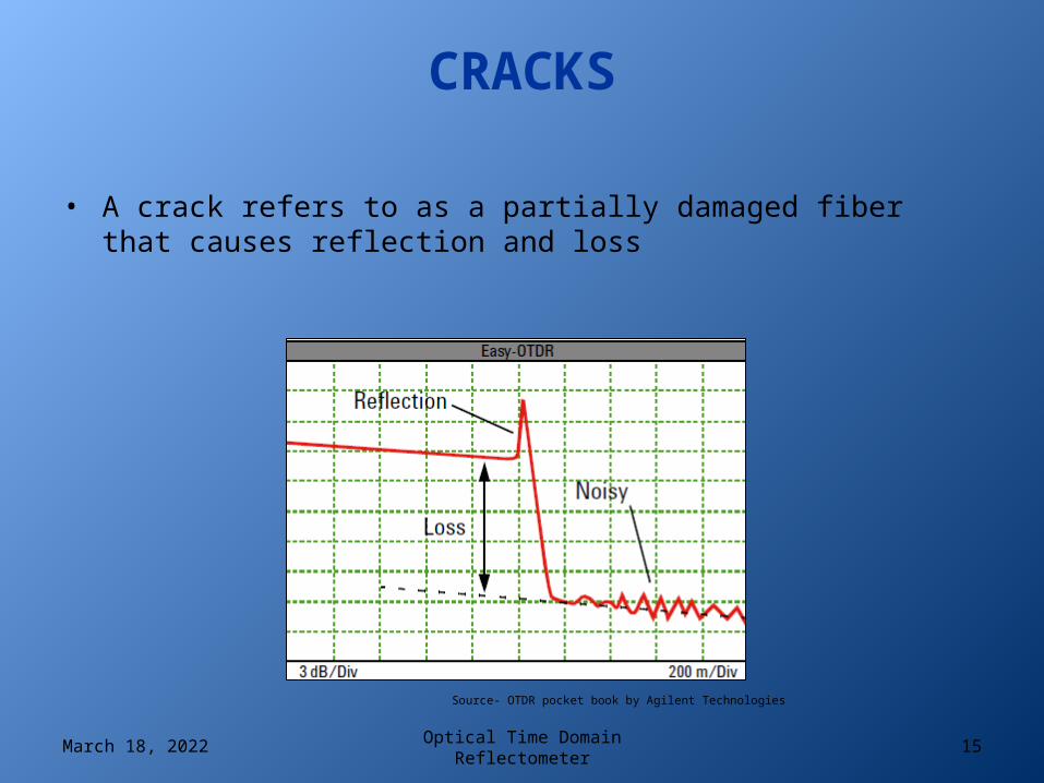
CRACKS
• A crack refers to as a partially damaged fiber that causes reflection and loss
April 17, 2023 15Optical Time Domain Reflectometer
Source- OTDR pocket book by Agilent Technologies
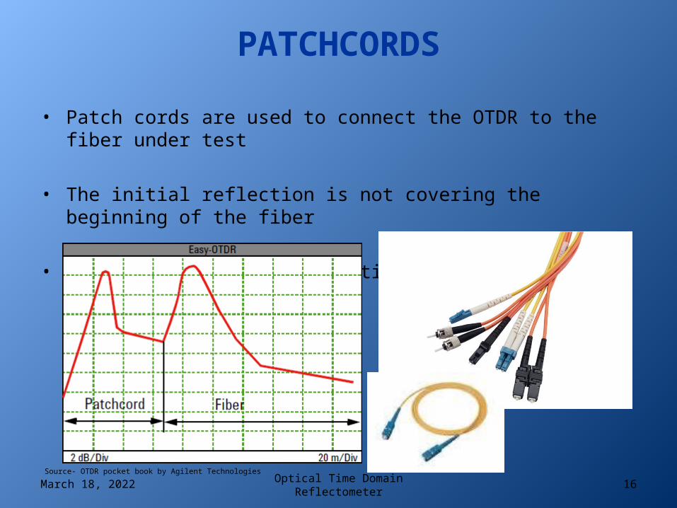
PATCHCORDS
• Patch cords are used to connect the OTDR to the fiber under test
• The initial reflection is not covering the beginning of the fiber
• This allows better examination of the first connector
April 17, 2023 16Optical Time Domain ReflectometerSource- OTDR pocket book by Agilent Technologies

FACTORS AFFECTING OTDR TRACE
• Dead zone
• Pulse width
• Dynamic range
April 17, 2023 Optical Time Domain Reflectometer 17

DEAD ZONE
• The time during which the detector is temporary blinded by a high amount of reflected light, until it recovers and can read light again
– Assume yourself driving on a highway during night
• More reflection causes the detector to take more time to recover, resulting in a longer dead zone
• Determines how close together two events can be measured
• Dead zone increases as the pulse width increases
April 17, 2023 Optical Time Domain Reflectometer 18

PULSE WIDTH• The time during which the laser is ON
• The shorter the pulse, the less energy it carries and the shorter the distance it travels due to the loss along the link (i.e., attenuation, connectors, splices, etc.).
• A long pulse carries much more energy for use in extremely long fibers
April 17, 2023 Optical Time Domain Reflectometer 19
NOISY TRACE
• Increased averaging time– Results in a considerable improvement in SNR, while maintaining the good
resolution of the short pulse. – does not improve SNR indefinitely.
• Longer Pulse width– Use the next available higher pulse (more energy). – Dead zones extend along with the pulse width
April 17, 2023 Optical Time Domain Reflectometer 20
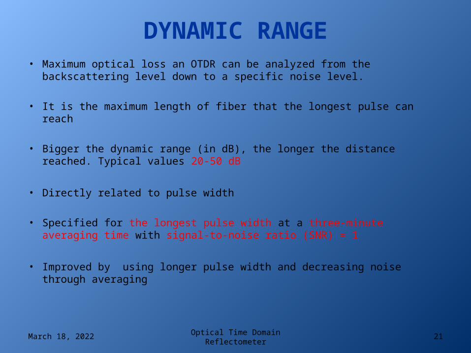
DYNAMIC RANGE• Maximum optical loss an OTDR can be analyzed from the backscattering level
down to a specific noise level.
• It is the maximum length of fiber that the longest pulse can reach
• Bigger the dynamic range (in dB), the longer the distance reached. Typical values 20-50 dB
• Directly related to pulse width
• Specified for the longest pulse width at a three-minute averaging time with signal-to-noise ratio (SNR) = 1
• Improved by using longer pulse width and decreasing noise through averaging
April 17, 2023 Optical Time Domain Reflectometer 21
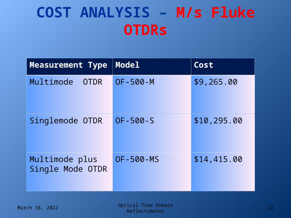
COST ANALYSIS – M/s Fluke OTDRs
Measurement Type Model Cost
Multimode OTDR OF-500-M $9,265.00
Singlemode OTDR OF-500-S $10,295.00
Multimode plus Single Mode OTDR
OF-500-MS $14,415.00
April 17, 2023 22Optical Time Domain Reflectometer

THANK YOU
April 17, 2023 23Optical Time Domain Reflectometer

REFERENCES
• http://www.EXFO.com/application note 194 by Jimmy Gagnon, Product Specialist, Optical Business Unit
• OTDR pocket guide – Agilent Technologies• Wikipedia
April 17, 2023 Optical Time Domain Reflectometer 24
TYPES OF FO CABLES
• Single-mode fibers – used to transmit one signal per fiber. They have small cores(9 microns in diameter) and transmit infra-red light from laser.
• Multi-mode fibers – used to transmit many signals per fiber (used in computer networks). They have larger cores(62.5 microns in diameter) and transmit infra-red light from LED.
April 17, 2023 25Optical Time Domain Reflectometer

FO CABLE
• Core – thin glass center of the fiber where light travels.• Cladding – outer optical material surrounding the core• Buffer Coating – plastic coating that protects the fiber.
April 17, 2023 26Optical Time Domain Reflectometer

TYPES OF CONNECTOR
TYPE FULL NAME COUPLING TYPE
SIZE USE
MT-RJ
Mechanical Transfer Registered Jack /Media Termination - recommended jack
Snap (duplex) 2.45×4.4 mm Duplex multimode
connections
SCSubscriber Connector /Square connector /Standard Connector
Snap (push-pull coupling) 2.5 mm
Datacom and telcom; extremely common
ST / BFOC
Straight Tip/Bayonet Fiber Optic Connector Bayonet 2.5 mm Multimode, rarely
single-mode;
April 17, 2023 27Optical Time Domain Reflectometer

INDEX OF REFRACTION (IOR)
• The Index of Refraction is a way of measuring the speed of light in a material.
• Light travels fastest in a vacuum.
• Index of Refraction is calculated by dividing the speed of light in a vacuum by the speed of light in some other medium (such as glass in the case of fiber optics!).
April 17, 2023 Optical Time Domain Reflectometer 28

OTDR SETUP – IOR• Each different optical glass fiber has a different refractive index profile
consistent with it’s type and manufacture process.
• Typical G.652.B singlemode fiber from Draka has an index number of 1.467 @ 1310nm and 1.468 @ 1550nm
• The longer the wavelength, the faster the light travels through the core.
• The user must set the OTDR to the proper GIR (Group Index of Refraction).
• If the GIR is not set to the proper number, the OTDR may overestimate or underestimate linear cable footage.
April 17, 2023 Optical Time Domain Reflectometer 29


