Embed Size (px)
Citation preview

OTA Measurement Suite

79
The OTA measurement suite is a collection of additional software and hardware modules for both StarLab and SG measurement systems. These add-ons allow for OTA performance capabilities and thus the testing of wireless devices in active mode. They facilitate the measurement process by simplifying the user interface and providing a software wizard for the measurements required for CTIA certification.
Measurement capabilities
• Total Isotropic Sensitivity• Total Radiated Power• Effective Isotropic Radiated Power• Effective Isotropic Sensitivity • Upper Hemisphere Partial Radiated Power • Upper Hemisphere Partial Isotropic Sensitivity• Near-Horizon Partial Isotropic Sensitivity• Near-Horizon Partial Isotropic Radiated Power• Intermediate channel
Certifications
• CTIA 2.2. certifiable measurements • CTIA 3.1 vendor audit**
Protocols*
• GSM, GPRS, EDGE• CDMA2000, CDMA 1xRTT, CDMA 1xEVDO• WCDMA, HSDPA, HSPA, HSPA+• LTE TDD/FDD• Wi-Fi 802.11 a/b/g/n• BLUETOOTH 802.15.1.2• PHS• TD-SCDMA, TD-HSDPA• WiMAX• GPS, A-GPS• DVB-H
* The list of compatible protocols is evolving on an on-going basis. Please contact us for updated information
** Our U.S. laboratory in Atlanta has received the CTIA 3.1 accreditation and MVG’s SG systems are on the CTIA Authorized Equipment List.
Software ■ SAM (OTA performance testing) SatEnv (measurement control & data acquisition) SMM (SATIMO Multi Measurement)
Equipment ■ Amplification unit■ Radio communication tester Active switching unit IO port switch (required only for WIFI with Anritsu MT8860C)
Accessories ■ PC Upright head phantom Head and hand phantoms Instrumentation rack Positioning laser pointer
Services ■ Installation■ Warranty■ Training Extended warranty CTIA certification assistance
Included Optional Required
System configurations
Main features
• Fast OTA measurements• User friendly interface
SOLUTION FOR• OTA Testing
+
I OTA Measurement Suite
3D radiation pattern of a radar
2
80
TRP is the total RF channel power radiated by a wireless terminal. It is calculated by integrating the measured Effective Isotropic Radiated Power (EIRP) data over the measurement sphere. The EIRP is measured every 15 degrees in both elevation and azimuth, at a minimum.
This accounts for a total of 1656 measurement points (23 elevations × 12 azimuths × 2 polarizations × 3 frequencies), with a typical measurement time of about 3 minutes (depending on the protocol and equipment).
Data Acquisition& Processing PC
Radio CommunicationTester
Ampli�cationUnit
Link antenna
System overview / TRP configuration
3
I OTA Measurement Suite
81
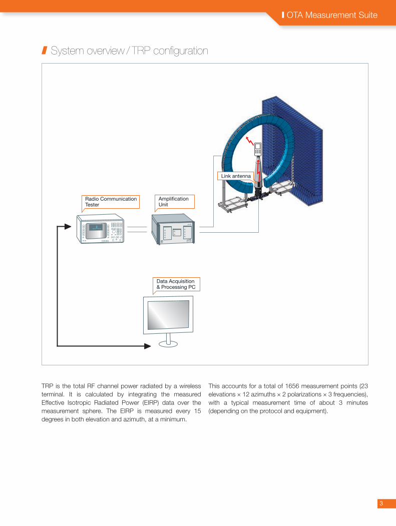
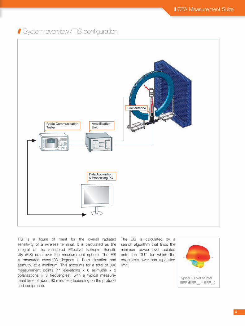
TIS is a figure of merit for the overall radiated sensitivity of a wireless terminal. It is calculated as the integral of the measured Effective Isotropic Sensiti-vity (EIS) data over the measurement sphere. The EIS is measured every 30 degrees in both elevation and azimuth, at a minimum. This accounts for a total of 396 measurement points (11 elevations × 6 azimuths × 2 polarizations × 3 frequencies), with a typical measure-ment time of about 90 minutes (depending on the protocol and equipment).
The EIS is calculated by a search algorithm that finds the minimum power level radiated onto the DUT for which the error rate is lower than a specified limit.
Data Acquisition& Processing PC
Radio CommunicationTester
Ampli�cationUnit
Link antenna
System overview / TIS configuration
I OTA Measurement Suite
Typical 3D plot of total EIRP (EIRPtheta + EIRPphi )
43

82
To ensure the compliance of wireless devices, it is required to undertake comprehensive Assisted GPS OTA antenna measurements that meet the demands of the CTIA certification standards.
MVG's multi-probe antenna measurement technology minimizes the mechanical movements required to test a device-under-test (DUT). When used in conjunction with an anechoic chamber and instrumentation, the system is compliant with the standards specified for CTIA certification of wireless devices.
The incorporated software facilitates the measurement process by simplifying the user interface and providing a software wizard for the measurements required for CTIA certification.
The system performs a comprehensive set of measure-ments consistent with the CTIA certification standards. These include the characterization of antenna radiation pattern (C/N), linearization, sensitivity (peak, TIS, UHIS, and PIGS), as well as intermediate channel degrada-tion (ICD). These tests ensure that interference from cellular communication across the band does not degrade the GPS performance of the wireless device.
Data Acquisition& Processing PC
MotionController
GPS Signal Generator
Radio CommunicationTester
Ampli�cation Unit
GSM/CDMA/WCDMA
GPS
ElevationScanned ElectronicallyVia Satimo Probe Array
Azimuth Scanned MechanicallyVia Turntable
System overview / A-GPS
5
I OTA Measurement Suite

83
I OTA Measurement Suite
Estimated time for TIS measurements (one channel with a sampling every 30°)
Standards GSM CDMA WCDMA WiFi CTIA GPRS 1xEvDO HSDPA Bluetooth Approved EDGE LTE FDD TDD Method
Sensitivity Algorithms
Classical 60 min 90 min 45 min 60 min Yes
Normalization - 60 min - 65 min Yes
Based on linearized RSSI pattern 10 min - 10 min - Yes
Start from RSSI 20 min - 30 min - Yes (8-10 with conf. level)
Based on EIRP pattern - - - 10 min No
Quick CDMA - 8 min - - No
SHORTER MEASUREMENT TIME
MVG offers several methods to reduce the TIS mea-surement time. One method, the TIS based on the Rx level, uses the DUT receiver as a power meter with certain communication protocols (like GSM and WCDMA). From each measurement point on the measurement sphere, a constant power is radiated towards the DUT. The DUT receiver then reports back its received power level and the complete spherical set of power level data can be referenced to a single-point EIS measurement to determine the TIS.
Software
SAM is the software interface for automated OTA performance testing with StarLab and SG measurement systems. It enables the measurements of both radiated power and sensitivity, supporting most of the common wireless communications protocols:GSM, GPRS, EDGE, CDMA2000, CDMA 1xRTT, CDMA 1xEVDO, WCDMA, HSDPA, HSPA, HSPA+, LTE TDD/FDDWi-Fi 802.11 a/b/g/n, BLUETOOTH 802.15.1.2, PHS, TD-SCDMA, TD-HSDPA, (Contact us for an updated list).
CTIA Reporting - Various Formats
Data can be exported in different formats, such as tab limited ascii formats, binary, XML or NetCDF Format. The user can adjust the file content to his/her requirements: separate data according to parameters or save only a part of the measurement. Reports can be automatically generated in any format supported by Windows. The content and lay out of the format can be adapted to specific requirements, such as the CTIA certification reports.Step by step Guided User Interface
65

84
A Multi-profile User Interface
SAM offers different measurement configurations, depen-ding on the user's level of expertise. Users with limited experience are guided through the different measurement steps, whereas more experienced users can access a full range of parameters.
Hardware configuration
• Radio communication tester: Base station simulator with measurement capabilities. It is the signal generator and measurement receiver.
• Amplification unit: Includes uplink/downlink switch for the SG or StarLab systems.
• Link antenna: A low reflectivity antenna mounted inside the positioning mast, close to the turntable.
It rotates with the DUT, maintaining a constant link, which reduces the risk of dropped calls during testing.
• Active switching unit (optional): Allows automatic switching between different test equipment.
• I/O switch port (optional): Used specifically with the MT8860C Anritsu WLAN test to separate the Radio Frequency IN/OUT port of the tester into 2 different paths: one for Transmitting (Tx) and one for Receiving (Rx).
Expert Mode User Interface
7
I OTA Measurement Suite

85
I OTA Measurement Suite
OTA head phantom and positioner kit
87 Copyright MVG 2014Product specifications and descriptions in this datasheet are subject to change without notice.
Actual products may differ in appearance from images shown.